
Optimum Location/Area of PZT Actuators for Flutter Damping ... · suppression are obtained using a...
20
Optimum Location/Area of PZT Actuators for Flutter Damping Using Norm Feedback Control Gain-Based Iterative Method Sallam A. Kouritem 1) , Mohamed M.Y.B. Elshabasy 2) and Hassan A. El-Gamal 3) 1), 2), 3) Department of Mechanical Engineering, Alexandria University, teaching assistant at faculty of engineering, Alexandria, Egypt 1) [email protected] ABSTRACT In the current investigation; an ad-hoc iterative methodology is proposed to select the optimum location and area of the piezoelectric actuator for damping of panel flutter. The finite element formulation of the equations of motion of the fluttering panel is obtained using the four node Bogner Fox Schmit (BFS) element. The electrical degree of freedom is presented to model piezoelectric actuator and the linear piezoelectricity constitutive relations are used. The von Karman large- deflection strain-displacement relations and the first order shear deformation theory for laminated panels are used. for aerodynamic loading; the quasi steady first-order piston theory is used. The time consumed in solving the system of the derived nonlinear equations is reduced using the modal transformation. The gain factor is obtained using the output feedback controller using a Linear Quadratic Regulator (LQR) full state feedback. A modal participation and optimal number of modes is presented. The optimal size and location of piezoelectric actuators to improve the flutter suppression are obtained using a norm feedback control gain-based iterative method as will be comprehensively discussed in the paper. The results show that the proposed method gives better results than those obtained by the norm of the optimal feedback control gain (NFCG). The PZT size and flutter damping time represent our assessment criteria. Keywords: Flutter Damping; Piezoelectric; Actuator; Finite Element; Control; NFCG; LQR; Iterative Method 1. Introduction Supersonic Panel flutter is a self-excited oscillation of a shell or plate when exposed to airflow along its surface. The earliest reported structural failures that can be assigned to panel flutter were the failures of early German V-2 rockets during World War II (Zhou et al. 1994,b). Recently there has been a huge interest in supersonic/hypersonic flight vehicles.
Transcript of Optimum Location/Area of PZT Actuators for Flutter Damping ... · suppression are obtained using a...

Optimum Location/Area of PZT Actuators for Flutter Damping Using Norm Feedback Control Gain-Based Iterative Method
Sallam A. Kouritem1), Mohamed M.Y.B. Elshabasy2) and Hassan A. El-Gamal3)
1), 2), 3) Department of Mechanical Engineering, Alexandria University, teaching assistant at
faculty of engineering, Alexandria, Egypt
ABSTRACT
In the current investigation; an ad-hoc iterative methodology is proposed to select the optimum location and area of the piezoelectric actuator for damping of panel flutter. The finite element formulation of the equations of motion of the fluttering panel is obtained using the four node Bogner Fox Schmit (BFS) element. The electrical degree of freedom is presented to model piezoelectric actuator and the linear piezoelectricity constitutive relations are used. The von Karman large-deflection strain-displacement relations and the first order shear deformation theory for laminated panels are used. for aerodynamic loading; the quasi steady first-order piston theory is used. The time consumed in solving the system of the derived nonlinear equations is reduced using the modal transformation. The gain factor is obtained using the output feedback controller using a Linear Quadratic Regulator (LQR) full state feedback. A modal participation and optimal number of modes is presented. The optimal size and location of piezoelectric actuators to improve the flutter suppression are obtained using a norm feedback control gain-based iterative method as will be comprehensively discussed in the paper. The results show that the proposed method gives better results than those obtained by the norm of the optimal feedback control gain (NFCG). The PZT size and flutter damping time represent our assessment criteria. Keywords: Flutter Damping; Piezoelectric; Actuator; Finite Element; Control; NFCG; LQR; Iterative Method
1. Introduction Supersonic Panel flutter is a self-excited oscillation of a shell or plate when exposed to
airflow along its surface. The earliest reported structural failures that can be assigned to panel flutter were the failures of early German V-2 rockets during World War II (Zhou et al. 1994,b). Recently there has been a huge interest in supersonic/hypersonic flight vehicles.

Because of their inherent high speed, the fuselage and cabinet panels of these vehicles are subjected to fluttering phenomena. In 1965, Johns ( 1965) introduced a survey of panel flutter and related research in NATO countries. (Mei et al. 1999, b) provided a review of nonlinear panel flutter at supersonic and hypersonic speeds. (Chowdary et al. 1994, b) used the finite element method with a quadratic iso-parametric element to study the flutter and free vibration characteristics of laminated composite panels. (Raja et al. 2006, b) proved that flutter speed can be enhanced using piezoelectric actuator. They proved that the bending-torsion flutter instability actively postponed from 44.13 to 55.5 m/s using the energy imparted by the multilayered piezoelectric actuators. (Zhou et al. 1994, b) categorized the panel flutter behavior into different five types, which includes flat, buckled, limit-cycle, periodic and chaotic motions for different values of non-dimensional aerodynamic pressure and it’s critical value (Abdel-Motaglay et al. 1999) studied the consequence of changing the flow yaw angle on the shape of limit-cycle deflection. Vedeneev ( 2012) Studied flutter boundaries by a complete numerical technique of single mode flutter. Moon and Kim ( 2003) derived the governing equations of the electromechanically coupled composite panel flutter using a Hamilton’s principle. Forster and Yang ( 1998) used the piezoelectric actuator to control flutter of aluminum wing boxes. Lock (1961) Studied the flutter of flat panels and used the ideal flutter theory to forecast the boundaries of these panels.
Pidaparti (1993) used a 48 degrees of freedom doubly curved quadrilateral thin shell finite element in the study of the supersonic flutter of cantilevered curved composite panels. (Yucheng et al. 1999, b) presented a formulation based on the FEM in modal coordinates for solving thermal post buckling drawbacks, where the deflection shape change was detected and participation of each mode was determined. Guo and Mei ( 2006) used the aero-elastic modes, instead of the traditional in vacuo-natural modes to reduce the number of coupled nonlinear modal equations of the large amplitude nonlinear panel flutter analysis at an arbitrary yawed supersonic flow angle and elevated temperatures.
(Moon et al. 2002, Moon 2006) used the genetic algorithm to determine the optimal shape and location of the piezoelectric sensors and actuators to augment control authority. Xu and Koko ( 2004) proved that the location of piezoelectric sensors and actuators had significant influence on the integrated system and control performance. Zheng and Yang ( 2012) revealed that the vibration control can be improved by increasing the number of the (PZT) bonded actuators. Lotfy and Elnomrossy (2009) proved that the control effect of piezoelectric material patches increases as long as they are placed away from the panel boundary. (Lee et al. 2002) revealed that the optimal piezoelectric actuator size is directly proportional to the excitation level. (Abdel-Motagaly 2001, Otiefy and Negm 2011) determined the optimum locations of actuators and sensors using the norm of feedback control gains (NFCG) and norm of Kalman filter estimator gains (NKFEG). Li and Narita (2013) demonstrated that increasing of the aerodynamic causes the buckling to occur before the flutter. Li and Song (2013) analyzed the aero-thermo-elastic properties of laminated panels and investigated the flutter and thermal buckling control of the structural system.

In the present study, the optimum location and size of piezoelectric concurrent actuator/sensor is determined using a methodology of combing the norm feedback control gain (NFCG) and the guided iteration method. The NFCG guide us to the hot-spot of placing the PZT element and the iteration is taking place around the NFCG-elected position. Thus the short name of the proposed methodology which will be comprehensively discussed later is the "NFCG-based iterative method".
The present paper is composed of six sections. The first one is the finite element formulation of the governing equations. In this section, the modal formulation is also presented. To determine the number of fluttering dominant modes, the modal participation is discussed in the second section. In the third section, the implemented control methodology is indicated. The fourth section contains the meshing density and the numerical analysis implemented in the current investigation. The proposed optimum placement of the PZT element and the results are shown and comprehensively discussed in the fifth section. The last section includes the concluding remarks.
2. Finite Element Formulation The Finite element formulation is used here to determine the dynamic response of the
panel integrated with PZT actuators. The finite element formulation is based on the Bogner-Fox-Schmit (BFS) C1 (Bogner et al. 1965, b) confirming rectangular elements. Each element consists of 16 bending degree of freedom (DOF) and 8 in-plane degree of freedom (DOF). The electrical degree of freedom is assumed to be constant throughout the plan area of each piezoelectric layer and to vary linearly through the thickness. The electrical degrees of freedom can be expressed as:
𝑤ᵩ = 𝑉1 ,𝑉2 ,… , 𝑉𝑛𝑝 (1)
Where theVi isthe electric potentials applied to or detected from the piezoelectric layers of the element, and np denotes the total number of piezoelectric layers.
2.1 Constitutive Equations The derivation of equations of motion is based on the thin panel assumption. Besides,
the effects of the rotary inertia and transverse shear deformation are neglected. The Von Karman nonlinear strain-displacement relations are expressed as:
ԑ𝑥ԑ𝑦𝛾𝑥𝑦
=
𝑢,𝑥
𝑣,𝑦
𝑢,𝑦+𝑣,𝑥
+ 1
2
𝑤,𝑥2
𝑤,𝑦2
2𝑤,𝑥𝑤,𝑦
+𝑧
−𝑤,𝑥𝑥
−𝑤,𝑦𝑦
−2𝑤,𝑥𝑦
= ԑ𝑚0 + ԑ𝜃
0 + 𝑧 𝑘 (2)
Where 𝑢 and 𝑣 are the in-plane displacements and x, y, z Cartesian coordinates. The
membrane strains ԑm0 and ԑθ
0 are due to in-plane displacements and large deflections,
respectively. For an aircraft panel consisting of hosting panel and piezoelectric layers without
temperature change, the stress-strain relationships for a general 𝑘𝑡ℎ layer, either the fiber-
reinforced composite( set 𝐸3𝑘 ) or the piezoelectric layercan written as(Zhou, Mei et al. 1996).
𝜎𝑥𝜎𝑦𝜏𝑥𝑦
𝑘
=
𝑄 11 𝑄 12 𝑄 16
𝑄 12 𝑄 22 𝑄 26
𝑄 16 𝑄 26 𝑄 66
𝑘
휀𝑥휀𝑦𝛾𝑥𝑦
− 𝐸3𝑘
𝑑𝑥𝑑𝑦𝑑𝑥𝑦
𝑘
(3)
For piezoelectric layers, the corresponding electric displacements are only detected
along the poling axis. The electrical displacement for the kth layer (Zhou et al. 1996, b) can expressed as
𝐷3𝑘 = 𝑑𝑥𝑑𝑦𝑑𝑥𝑦 𝑘
𝑄 11 𝑄 12 𝑄 16
𝑄 12 𝑄 22 𝑄 26
𝑄 16 𝑄 26 𝑄 66
𝑘
휀𝑥휀𝑦𝛾𝑥𝑦
− 𝐸3𝑘
𝑑𝑥𝑑𝑦𝑑𝑥𝑦
𝑘
+ 휀33𝑘 𝜎 𝐸𝑖𝑘 (4)
Where 𝑄 𝑘and 𝑑 𝑘are the lamina stiffness and stress/charge constants, respectively. The resultant in-plane forces and moments acting on a laminate are obtained by
integration of stresses in each layer or laminate through the lamina thickness,
𝑁 , 𝑀 = 𝜎 𝑘 1, 𝑧
ℎ/2
−ℎ/2
𝑑𝑧 (5)
Which, lead to the constitutive relations for a laminated panel:
𝑁𝑀 =
𝐴 𝐵 𝐵 𝐷
휀0
𝑘 −
𝑁∅𝑀∅
(6)
The laminate stiffness matrices are given by:
𝐴 = 𝑄 𝑘 𝑧𝑘+1 − 𝑧𝑘
𝑛
𝑘=1
𝐵 = 1
2 𝑄 𝑘 𝑧𝑘+1
2 − 𝑧𝑘2
𝑛
𝑘=1
𝐷 = 1
3 𝑄 𝑘 𝑧𝑘+1
3 − 𝑧𝑘3
𝑛
𝑘=1
(7)

Where 𝐴 , 𝐵 , 𝐷 are in-plane, coupling and bending stiffness matrices. The piezoelectric
in-plane force 𝑁∅ , is set equal to zero. This is achieved by having the same piezoelectric
layer to be used as actuator and sensor concurrently(Abdel-Motagaly et al. 2005, b).The piezoelectric element used is bending moment element because the actuation produced from bending moment is much more efficient than in-plane tension for nonlinear panel flutter suppression Moon and Hwang (2005).
2.2 First-Order Piston Aerodynamic theory For panel flutter at high supersonic flow first-order piston theory (Zhou et al. 1996, Guo
et al. 2005, qinqin 2005) is usually used. The aerodynamic load can be written as:
𝑃𝑎 = −2𝑞
𝛽 𝜕𝑤
𝜕𝑥+𝑀∞
2 − 2
𝑀∞2 − 1
1
𝑉
𝜕𝑤
𝜕𝑡
= − 𝜆𝐷110
𝐿3
𝜕𝑤
𝜕𝑥+𝑔𝑎𝑤0
𝐷110
𝐿4
𝜕𝑤
𝜕𝑡
(8)
Where; 𝑃𝑎 is the aerodynamic pressure, The subscript a is the air, 𝑉 is the airflow
velocity, 𝑀∞ is the mach number, q=1
2𝜌𝑎 𝑉
2 is the dynamic pressure 𝜌𝑎 is the air mass
density, 𝛽 = 𝑀∞2 − 1, w is the panel lateral displacement, 𝐷110 is the bending stiffness
matrix D for beam; (for composite plates,𝐷110 is the first element in the laminate bending stiffness matrix D calculated when all the fibers of the composite plate are aligned in the x-direction); L is the panel length. Notice that
𝜆 =2𝑞𝐿3
𝛽𝐷110 , 𝜇 =
𝜌𝑎
𝜌ℎ, 𝐶𝑎 =
𝑀∞2 −2
𝑀∞2 −1
2𝜇
𝛽, 𝑔𝑎 =
𝜌𝑎 𝑉 𝑀∞2 −2
𝛽3 𝜌ℎ𝑤𝑜= 𝜆𝐶𝑎 ,𝑤0 =
𝐷110
𝜌ℎ𝐿4 (9)
Where, 𝜆 is the non-dimensional dynamic pressure; 𝜇 is the mass ratio; 𝑔𝑎 is non-dimensional aerodynamic damping and 𝐶𝑎 is its coefficient; and 𝑤0 is a reference frequency.
2.3 Equations of Motion
Using the Hamilton’s principle(Li 2012 , qinqin 2005) the finite element equations for the laminated composite plate with fully coupled electrical-structural properties can be derived from
𝛿 𝑇 − 𝑈 + 𝑊𝑒
𝑡2
𝑡1
= 0 (10)
Where T and U are the kinetic and strain energy of the system, 𝑊𝑒expresses the electrical
energy and 𝑡1 and 𝑡2are the integration limits. After substitution of the expressions for T, U

and 𝑊𝑒 into Equation (10) we get,
𝜌 𝛿𝑤 𝑇𝑤 + 𝛿𝑢.𝑇𝑢 + 𝛿𝑣 𝑇𝑣 − 𝛿𝜖 𝑇 𝜎 + 𝛿𝐸 𝑇 𝐷 𝑑𝑉 = 0
𝑉
(11)
The volume integral can be reduced to area integral by first integrating the constitutive
equations. With the use of finite element formulation, the equation of motion for rectangular plate element subjected to a dynamic pressure and electrical field with aerodynamic damping are obtained as
𝑀 0
0 0 𝑊
𝑊 ∅ +
𝐺 00 0
𝑊
𝑊 ∅ + 𝜆
𝐴 00 0
+ 𝐾 𝐾𝑤∅
𝐾∅𝑤 𝐾∅ +
𝐾1 00 0
+
𝐾2 0
0 0
𝑊𝑊∅
= 00 (12)
Where, 𝑀 , 𝐺 , 𝐴 , and 𝐾 are, mass, aerodynamic damping, aerodynamic influence, and linear stiffness matrices, respectively. 𝐾1 and 𝐾2 depend linearly and quadratically on
element displacements respectively. 𝑊∅ , 𝐾𝑤∅ , 𝐾∅𝑤 and 𝐾∅ are collected as the PZT
elements work as actuators and sensors at the same time. Thus; the equations for self-sensing actuators are,
𝑀 𝑊 + 𝐺(𝜆,𝐶𝑎) 𝑊 + 𝜆 𝐴 + 𝐾 + 𝐾1 + 𝐾2 𝑊 = − 𝐾𝑤∅ 𝑊∅ (13)
𝑄 = 𝐾∅𝑤 𝑊
= − 𝐾∅ 𝑊∅
(14)
(15)
Where;
𝑄 𝑤ℎ𝑖𝑐ℎ 𝑟𝑒𝑝𝑟𝑒𝑠𝑒𝑛𝑡𝑠 𝑎𝑐𝑡𝑢𝑎𝑡𝑜𝑟 𝑎𝑛𝑑 𝑠𝑒𝑛𝑠𝑜𝑟 𝑐𝑜𝑙𝑙𝑒𝑐𝑡𝑒𝑑 𝑣𝑒𝑐𝑡𝑜𝑟 𝑐ℎ𝑎𝑟𝑔𝑒𝑠 = 𝑄𝑎
𝑄𝑠
𝑊∅ = 𝑊∅
𝑎
𝑊∅𝑠
𝐾∅ = 𝐾∅
𝑎 0
0 𝐾∅𝑠
(16)
2.4 Modal Formulation
To largely decrease the number of scalar equations to a small number the modal
transformation is applied. This number equals to the participating modes number (Abdel-Motagaly et al. 2005, b). The bending displacements of the system as a linear combination of some known function are written as:
𝑊 = 𝑞𝑟 𝑡 ∅𝑟
𝑛
𝑟=1
= ∅ 𝑞 (17)
Where ∅ and 𝑞 are the element eigenvector and natural modal coordinate vector. The linear frequencies and the corresponding natural modes are obtained from the linear vibration of the system.
𝜔𝑟2 𝑀 ∅𝑟 = 𝐾𝑏 ∅𝑟 (18)
Since the element nonlinear stiffness matrices can be expressed in terms of the element
displacements 𝑊𝑏 and 𝑊𝑚 , this displacement vector can be expressed by the linear modes ∅𝑟 .The actuating equations of motion in modal coordinate become,
𝑀 𝑞 + 𝐺 𝑞 + 𝐾 + 𝐾 𝑞𝑞 𝑞 = − 𝐾 𝑤∅𝑎 𝑊 ∅
𝑎 (19)
For self-sensing actuators, 𝐾 𝑤∅𝑎 and 𝑊 ∅
𝑎 are substituted by 𝐾 𝑤∅ and 𝑊 ∅ . And the
sensing equation is
𝑞𝑠 = − 𝐾 ∅𝑤𝑠 𝑞 (20)
For self-sensing actuators, 𝐾 ∅𝑤𝑠 is substituted by 𝐾 ∅𝑤 , then in equation (19), the modal
mass, linear stiffness and aerodynamic damping matrices are,
M , K , G = ∅ T M , K , G(λ, Ca) ∅
The second order nonlinear modal stiffness matrix is,
𝐾 𝑞𝑞 = ∅ 𝑇 𝑞𝑟𝑞𝑠
𝑛
𝑠=1
𝑛
𝑟=1
𝐾2𝑏 𝑟𝑠 − 𝐾1𝑁𝑚 𝑊𝑚 2
𝑟𝑠
− 𝐾1𝑏𝑚 𝑟 𝐾𝑚
−1 𝐾1𝑚𝑏 𝑠 ∅
(21)
The modal piezoelectric control force is
𝐾 𝑤∅ = 𝐾 𝑤∅
𝑎
𝐾 𝑤∅𝑠
= ∅ 𝑇 𝐾𝑤∅
𝑎
𝐾𝑤∅𝑠
= ∅ 𝑇 𝐾𝑤∅ = 𝐾 𝑤∅ 𝑇 (22)
2.5 Modal Participation To determine the number of modes the modal participation is used(Abdel-Motagaly et
al. 2005) which is expressed as:

𝑃𝑎𝑟 𝑟−𝑡ℎ =𝑚𝑎𝑥 𝑞𝑟
𝑚𝑎𝑥 𝑞𝑠 𝑛𝑠=1
(23)
The modal participation values of the first four modes at various limit-cycle amplitudes for a simply supported square isotropic aluminum panel without piezoelectric material is shown in Table (1). Table 1 Modal participation values at various limit-cycle amplitudes
𝞴 𝑤𝑚𝑎𝑥 /Height Modal Participation, %
q11 q12 q13 q14
600 0.35 30.9 30.9 18.7 9.35
800 0.645 40.9 40.3 13.2 3.0
1000 0.66 37.5 35.8 12.2 9.6
As the total contribution of the first four modes,listed down in Table 1 at various limit cycle
amplitude or wmax /Heightis more than 90 %, these modes will be used and the others will be neglected. The truncation of Non-highly contributing modes saves the computational effort and the converging calculation time.
3. Control methodology In the current section the controller design and the linear quadratic regulator (LQR)
used in calculating the gains are discussed. 3.1 Controller Design A standard state space for control design and simulation can be written based on the
modal equations (21), which represent the states are assigned the state vector X.
X= 𝑞𝑞 (24)
The state space form for the modal equations of motion is
𝑋 =𝐴 𝑋, 𝑡 𝑋 + 𝐵𝑈 𝑌 = 𝐶𝑋 + 𝐷𝑈
(25)
Where; U= 𝑊∅ is the control input.Y= 𝑞𝑠 is the sensor output.
Where the system matrices are

𝐴= 0 𝐼
− 𝑀 𝑏 −1 𝐾 − 𝑀 𝑏
−1 𝐺 +
0 𝐼− 𝑀 𝑏
−1 𝐾 𝑞𝑞 𝑋, 𝑡 0
B= 0
− 𝑀 𝑏 −1 𝐾 𝑏∅
, C= − 𝐾 𝑏∅ 0 , D=0
(26)
Where 𝐴 is a real system state matrix. 𝐾 𝑏∅ Exists for self-sensing actuators. We use its
linearized form by applying Taylor series approach in designing a controller for the system.
The second part of 𝐴 represents the effect of nonlinear stiffness matrices of the panel. Using the linearization about the system reference point which, is the point with no
deflection 𝑞 =0. The second part of 𝐴 can be neglected and the linearized result A
matrix is the first part of 𝐴 which is defined as:
A= 0 𝐼
− 𝑀 𝑏 −1 𝐾 − 𝑀 𝑏
−1 𝐺 (27)
3.2 LQR Controller The linear quadratic regulator (LQR) is used to get the gain values for linear system.
The solution ofthe linear full state feedback using the (LQR) is written as:
U=-KX (28)
Where,K represents (LQR gain) vector. U is used to minimize the quadratic performance index, A functionJ of both system states and control effort is given by,
J= 𝑋𝑇 𝑄𝑋 + 𝑈𝑇𝑅𝑈 𝑑𝑡∞
0 (29)
Where; R is a symmetric positive definite control effort weighting matrix.Q is a symmetric positive semi-definite state weighting matrix. The solution of the controller gains that minimizes the performance index is,
K=𝑅−1𝐵𝑇𝑃 (30)
Where P is a positive definite symmetric matrix determined from the solution of the Riccati equation
𝐴𝑇 𝑃 + 𝑃𝐴 − 𝑃𝐵𝑅−1𝐵𝑇𝑃 + 𝑄 = 0 (31) 4. The meshing density and the numerical analysis To study the effect of piezoelectric material on damping the panel flutters four-sides
simply supported square isotropic Aluminum panel with dimensions(12×12×0.015 in.) is

used. The panel material is aluminum, while the piezoelectric layers are lead zirconate titanate (PZT5A) ceramics. The material properties of the aluminum panel and piezoelectric layers are shown in Table 2. The panel is modeled using a 24×6 (24 elements in x direction and 6 elements in y direction, with total of 144 rectangular elements).Self-sensing piezoelectric layers are perfectly attached on the top and bottom surfaces of panel to form an active panel. As discussed above, the only four modes (1,1),(1,2),(1,3) and (1,4) are used. Modal participations were calculated at different values of λ or at various values of Wmax/Height.
The Runge-Kutta numerical integration method was used to simulate the modal nonlinear models. Limit cycle oscillations (LCO) are associated with panel flutter. Free oscillations are generated by the panel when there is no dynamic pressure and there are no other damping and nonlinear effects in the system. The critical dynamic pressure is determined using Eigen-value analysis of the linear system Onawola ( 2008). Pure imaginary Eigen values are obtained in case of free vibration. When the aerodynamic pressure applied to the panel introduces damping and flow coupling terms which, lead to oscillations decaying. In this case, the system has complex Eigen values with negative real
parts. The rate of oscillations decaying increases as the dynamic pressure increases 𝜆 until it reaches the critical aerodynamic pressure 𝜆𝑐𝑟 at which there exists a pair of purely imaginary eigenvalues having negative real parts. Beyond this critical aerodynamic pressure, the pair of pure imaginary Eigenvalues become pure positive real parts and
gives unstable system. The critical aerodynamic pressure for the modeled aluminum 𝜆𝑐𝑟 is calculated and found to be 512 .Panel flutter limit cycle oscillations at aerodynamic pressure λ= 840 and 1200 are obtained.
Table 2 The properties of isotropic panel and PZT5A in SI units
Material Aluminum panel PZT5A(actuator and sensor)
Thickness hp =1.27 mm he = 3.81mm
Young modulus Ep =68.95 Gpa Ee =62GPa
Mass density 𝜌𝑝 =2700 kg/m3 𝜌𝑒 =7593 kg/m
3
Poisson’s ratio Vp=0.3 Ve =0.3
Coercive field Emax=600×103 v/m
Charge constant d31= -1.91×10⁻¹⁰
m/v, d32=d31, d36=0
5. Methodology of Optimum Placement of PZT The linear quadratic regulator (LQR) full state feedback is used to control the panel
flutter oscillations. The controller is activated at 0.2 second from the beginning of sensing the fluttering, where:
The PZT ceramic sense the magnitude of the highly contributing modes of the limit cycle motions of the panel flutter.

The sensed flutter (output signals) is fed to the controller which modifies/amplifies the signals that are feed back to the actuator.
This feedback action continues in actuating the panel to reduce the magnitudes of limit cycles until the PZT ceramic senses no flutter.
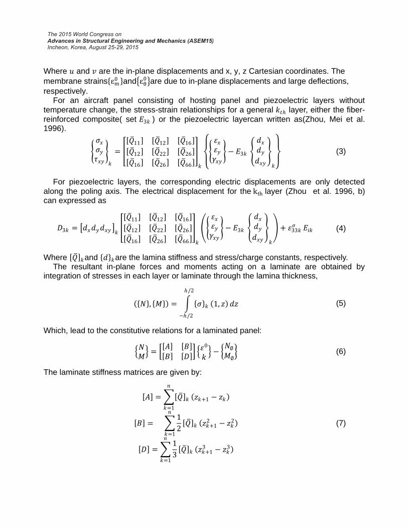
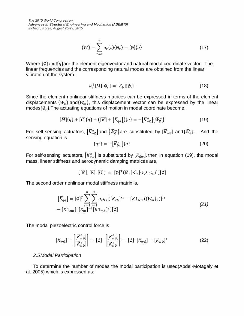
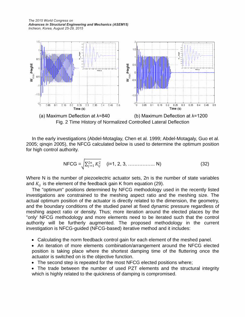
Figure 1 shows the mode shapes of the flutter panel obtained from the simulation code at λ = 840. The time evolutions of the controlled LCO panel flutter at λ = 840 and 1200 respectively are shown in Fig. 2. The all possible values of position and momentum variables of the controlled panel during the time progress are plotted in Fig. 3 (phase plot). The control input shown in Fig. 4is obtained by dividing the original control input by the maximum control voltage at the two values of the dynamic pressures.
(a) 1st mode (b)2nd mode
(c) 3rd mode (d) 4th mod
Fig.1 Flutter deflection mode shapes at λ=840
(a) Maximum Deflection at λ=840 (b) Maximum Deflection at λ=1200
Fig. 2 Time History of Normalized Controlled Lateral Deflection In the early investigations (Abdel-Motaglay, Chen et al. 1999; Abdel-Motagaly, Guo et al.
2005; qinqin 2005), the NFCG calculated below is used to determine the optimum position for high control authority.
NFCG = 𝐾𝑖𝑗22𝑛
𝑗=1 (i=1, 2, 3, …………….. N) (32)
Where N is the number of piezoelectric actuator sets, 2n is the number of state variables and 𝐾𝑖𝑗 is the element of the feedback gain K from equation (29).
The "optimum" positions determined by NFCG methodology used in the recently listed investigations are constrained to the meshing aspect ratio and the meshing size. The actual optimum position of the actuator is directly related to the dimension, the geometry, and the boundary conditions of the studied panel at fixed dynamic pressure regardless of meshing aspect ratio or density. Thus; more iteration around the elected places by the "only' NFCG methodology and more elements need to be iterated such that the control authority will be furtherly augmented. The proposed methodology in the current investigation is NFCG-guided (NFCG-based) iterative method and it includes:
Calculating the norm feedback control gain for each element of the meshed panel.
An iteration of more elements combination/arrangement around the NFCG elected position is taking place where the shortest damping time of the fluttering once the actuator is switched on is the objective function.
The second step is repeated for the most NFCG elected positions where;
The trade between the number of used PZT elements and the structural integrity which is highly related to the quickness of damping is compromised.
(a) Phase Plot at λ=840 (b) Phase Plot at λ=1200
Fig. 3 Phase Plot OF Controlled Panel Flutter
(a)The Control Input at λ=840 (b)The Control Input at λ=1200
Fig. 4 The Control Input of Controlled Panel Deflection
Comparing the results obtained by the traditional NFCG methodology with those
obtained from using the proposed methodology in this study, shows that the control authority is augmented. In other words, the same control authority obtained by the traditional NFCG method could be obtained with fewer number of PZT elements which are distributed with certain pattern using the NFCG-based iterative methodology proposed in the current investigation. On the other hand, the proposed methodology deals explicitly

with the flutter damping time, which is considered as the objective function. Recall that fluttering of the highly maneuverable air vehicles panel is very dangerous phenomena as it precariously affects their structural integrity. Therefore; the smaller the damping time the better the control methodology. Consequently; in the Mat Lab code used in the present study, the target time is the time at which the maximum displacement per panel height (Wmax/Height)is less than 0.0005.The NFCG are calculated based on aero-damping coefficient ca= 0.01 and control-weighting matrix R is 10*I "Identity Matrix".
The comparison between the conventional NFCG and the proposed NFCG-based method showed that the latter gives better control authority than the NFCG method as shown in Fig.5. Figure 5a shows that the flutter damping time at λ=840, using only two elements which are located by the proposed iterative method, is equal to 0.072 sec. This time is less than the damping time (0.0836 sec) obtained when using the same two elements which are distributed by the conventional NFCG method. Notice also that the larger the PZT elements which are located and distributed by the proposed method, the shorter the damping time. This behavior is not observed when the elements are located and distributed base on the NFCG method. Figure 5bshows that only 4 PZT elements located and distributed by the proposed method are enough to damp the fluttering within 0.0581sec. if the same four elements were placed and distributed by the NFCG method, the flutter takes 0.2187 sec to stop from the moment the PZT actuator was switched on. This is taking place at higher dynamic pressure which is equal to 1200. From the same figure, one can notice that smaller numbers of PZT elements which are selected and distributed by the proposed method are sufficient to sustain the panel structural integrity.
(a) Number of Piezoelectric patches and Time Relation at λ=840
(b) Number of Piezoelectric patches and
Time Relation at λ=1200
Fig. 5 Comparisons between The Efficiency of Iterative Method and NFCG Method

On the other hand and as mentioned before, there no lucid behavior related to the number of PZT elements selected by the conventional NFCG method. Comparing Figs. 5a and 5b, one can notice that the larger the dynamic pressure, the larger the flutter damping time. One can also notice that the larger the dynamic pressure the larger the number of PZT elements to be used as self-sensing actuator regardless of the methodology used in locating and distributing of these elements.
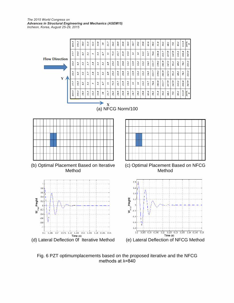
In Fig. 6, plan views of meshed panel are shown with dynamic pressure of 840. In Fig. 6a, the NFCG values calculated at each element are listed down on their own elements.
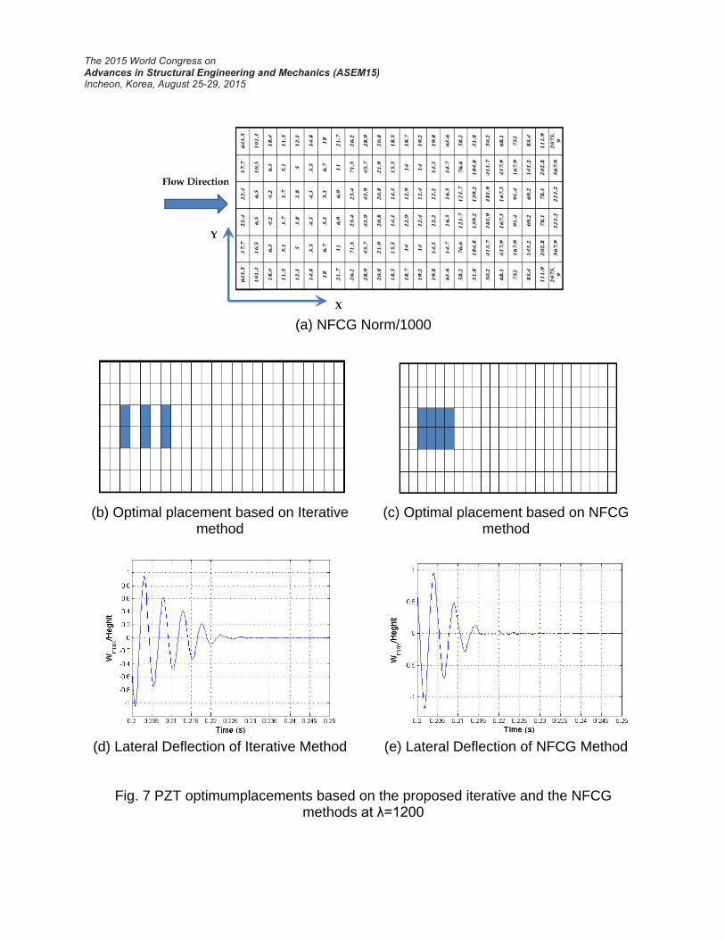
Notice that position of the four element selected by the conventional NFCG method are those of smallest NFCG values as shown in Fig. 6c. In Fig. 6b, the positions of the four elements are shifted two elements in x-direction and are still located on the places of small NFCG values. Figs. 6d and 6e show the history of the normalized maximum lateral deflection of the panel from the triggering moment of the PZT actuator till the complete damping for the NFCG and the NFCG-based iterative methodology respectively. Figs. 7a to 7e are similar to those in Fig.6 except the dynamic pressure which is 1200. In these figures, one can notice that the number of PZT elements required for flutter damping becomes larger but they are still around the small NFCG values locations. Comparing Figs. 7b and 7C, one can notice that the elements used in the proposed method are less than that of the NFCG method. Moreover, the elements in the NFCG method are collected while in the NFCG-based iterative are not. Also notice that the elements in the proposed method are 6 while in the NFCG method they are 8.Besides, the configurations in Fig.6 and 7 illustrate that the optimum shape at λ=840 and 1200 is rectangular shape (one set) using the NFCG method while, the optimal shape is rectangular at λ=840 and multi sets actuator at λ=1200 using the proposed method. Generally, it is noticed that location of PZT actuator is closer to the left side of panel from which the flutter wave is starting and the first interaction between the air stream and the panel is taking place. This is very intuitive as the damping action will be more effective if it was close to the source of stress wave propagation which is caused by the flutter phenomena.
In running of the created Mat Lab code, it is proved that the resulting optimal location and size at λ=1200shown in Fig.7 give structural integrity over a range of dynamic pressure which start from the critical value (λ=512) to λ=1200. It is also noticed that increasing the PZT elements do not enhance the structural integrity of the panel.
(a) NFCG Norm/100
(b) Optimal Placement Based on Iterative
Method
(c) Optimal Placement Based on NFCG Method
(d) Lateral Deflection 0f Iterative Method
(e) Lateral Deflection of NFCG Method
Fig. 6 PZT optimumplacements based on the proposed iterative and the NFCG methods at λ=840
(a) NFCG Norm/1000
(b) Optimal placement based on Iterative method
(c) Optimal placement based on NFCG method
(d) Lateral Deflection of Iterative Method
(e) Lateral Deflection of NFCG Method
Fig. 7 PZT optimumplacements based on the proposed iterative and the NFCG
methods at λ=1200

6. Conclusion The nonlinear panel fluttering of hypersonic/supersonic air-vehicles and reusable
space-vehicle threaten the structural integrity of these vehicles. The PZT elements which are used as self-sensing actuators strongly bonded with certain pattern to these panels and actively powered can damp this fluttering in a very short time. Selection of the number, location and distribution is the clue of augmenting the control authority. The actual place of the optimum control authority is related to the panel geometry, dimensions, and the panel ends conditions. Thus; combination between the meshing dependable methods (NFCG, NKFEG, etc.) proposed in the early literature and iteration needs to be implemented such that a higher control authority will take place. From the discussion through the last section, one can conclude that the proposed iterative methodology provide a cheaper solution for damping the flutter with higher control authority over the conventional methods. References Zhou, R. C., D. Y. Xue, et al. (1994). "Finite element time domain - modal formulation for
nonlinear flutter of composite panels." AIAA Journal 32(10): 2044-2052. Johns, D. J. (1965). "A Survey On Panel Flutter." Presented at the 21st Meeting of the
AGARD Structures and Materials Panelin Nancy,(North Atlantic Treaty Organization Advisory Group For Aerospace Research And Development).
Mei, C., K. Abdel-Motagaly, et al. (1999). "Review of nonlinear panel flutter at supersonic and hypersonic speeds." Applied Mechanics Reviews 52(10): 321-332.
Chowdary, T. V. R., S. Parthan, et al. (1994). "Finite element flutter analysis of laminated composite panels." computers & structures 53(2): 245-251.
Raja, S., A. A. Pashilkar, et al. (2006). "Flutter control of a composite plate with piezoelectric multilayered actuators." Aerospace Science and Technology 10(5): 435-441.
Zhou, R. C., C. Mei, et al. (1996). "Suppression of nonlinear panel flutter at supersonic speeds and elevated temperatures." AIAA Journal 34(2): 347-354.
Abdel-Motaglay, K., R. Chen, et al. (1999). "Nonlinear flutter of composite panels under yawed supersonic flow using finite elements." AIAA Journal 37(9): 1025-1032.
Vedeneev, V. V. (2012). "Panel flutter at low supersonic speeds." Journal of Fluids and Structures 29(0): 79-96
Vedeneev, V. V. "Effect of damping on flutter of simply supported and clamped panels at low supersonic speeds." Journal of Fluids and Structures(0).
Moon, S. H. and S. J. Kim (2003). "Suppression of nonlinear composite panel flutter with active/passive hybrid piezoelectric networks using finite element method." Composite Structures 59(4): 525-533.
Forster, E. E. and H. T. Y. Yang (1998). "Flutter control of wing boxes using piezoelectric actuators." Journal of Aircraft 35(6): 949-957.
lock, m. h. (1961). "A study of two-dimensional panel flutter." california institute of techenology(doctor of philosophy).
Pidaparti, R. M. V. (1993). "Flutter analysis of cantilevered curved composite panels." Composite Structures 25(1–4): 89-93.
Yucheng Shi, R. Y. Y. L. C. M. (1999). "Thermal postbuckling of composite plates using the finite element modal coordinate method." Journal of Thermal Stresses 22(6): 595-614.
Guo, X. and C. Mei (2006). "Application of aeroelastic modes on nonlinear supersonic panel flutter at elevated temperatures." Computers & Structures 84(24–25): 1619-1628
Moon, S., C. Yun, et al. (2002). "Passive suppression of nonlinear panel flutter using piezoelectric materials with resonant circuit." KSME International Journal 16(1): 1-12.
Moon, S. H. (2006). "Finite element analysis and design of control system with feedback output using piezoelectric sensor/actuator for panel flutter suppression." Finite Elements in Analysis and Design 42(12): 1071-1078.
S.X. Xu, T. S. K. (2004). "Finite element analysis and design of actively controlled piezoelectric smart structures " Finite Elements in Analysis and Design 40(Research and Emerging Technologies Department, Canada): 241–262.
Bin Zheng , J. Y. (2012). "Vibration analysis of base structure on SINS using PZT actuators." Eng & Comp Science 20.
M. Lotfy, M. E. (2009). "Active composite panel flutter using finite element method." Aerospace Sciences & Aviation Technology, ASAT-13-ST-25.
Lee, Y. Y., K. K. Yuen, et al. (2002). "Numerical simulation model of vibration responses of rectangular plates embedded with piezoelectric actuators." Thin-Walled Structures 40(1): 1-28.
Abdel-Motagaly, K. (2001). "Finite element analysis and active control for nonlinear flutter of gompite panels under yawed supersonic flow." Doctor of philosophy (Aerospace Engineering Old Dominion University).
Otiefy, R. A. H. and H. M. Negm (2011). "Wing box transonic-flutter suppression using piezoelectric self-sensing diagonal-link actuators." International Journal of Solids and Structures 48(1): 31-43.
Li, J. and Y. Narita (2013). "Analysis and optimal design for supersonic composite laminated plate." Composite Structures 101(0): 35-46.
Li, F.-M. and Z.-G. Song (2013). "Flutter and thermal buckling control for composite laminated panels in supersonic flow." Journal of Sound and Vibration 332(22): 5678-5695.
Bogner, F.K., Fox R.L.and Schmit L. A. (1965). "The generation of international compatible stiffness and matrices by the use of interpolation formulas" proceeding of the conference on matrix methods in structural mechanics, wright-patterson air force base, ohio, pp, 397-444
Abdel-Motagaly, K., X. Guo, et al. (2005). "Active control of nonlinear panel flutter under yawed supersonic flow." AIAA Journal 43(3): 671-680.

Moon, S. H. and J. S. Hwang (2005). "Panel flutter suppression with an optimal controller based on the nonlinear model using piezoelectric materials." Composite Structures 68(3): 371-379.
Li, F.-M. (2012). "Active aeroelastic flutter suppression of a supersonic plate with piezoelectric material." International Journal of Engineering Science 51(0): 190-203.
qinqin (2005). "Active control of large amplitude nolinear free vibrations and nonlinear supersonic panel flutter of beams and composite plates using piezoelectric self-sensing actuator." old dominion university Master of Science Thesis.
Onawola, O. O.(2008). "A feedback linearization approach for panel flutter suppression with piezoelectric actuation." Doctor of Philosophy(Auburn University, Alabama)


![PZT 압전재료.ppt [호환 모드]](https://static.fdocuments.us/doc/165x107/61b3808861533b67b44eb4fc/pzt-ppt-.jpg)
