Optimum Energy and By-Product Recovery in Chlorinated ...
20
RP THRM-1 \ DECEMBER 1982 Reprinted with the permission of: The American Society of Mechanical Engineers 1982 ASME National Waste Processing Conference ___ Tahnid Paner
Transcript of Optimum Energy and By-Product Recovery in Chlorinated ...

RP THRM-1 \ DECEMBER 1982
Reprinted with the permission of: The American Society of Mechanical Engineers
1982 ASME National Waste Processing Conference ___
Tahnid Paner

i

Optimum Energy and By-product Recovery in Chlorinated Hydrocarbon Disposal Systems
BY
Abstract With the increase in production over recent years in the plastics industry, the generation of wastes from vinyl chloride and polyvinyl chloride processes has expanded rapidly. In many of the larger facilities where an increasing amount of products is produced, an equal increase in toxic gaseous vents and viscous liquid waste materials results. Since these materials have been determined to be carcinogenic, it is necessary to dispose of them properly. However, because of the high quantity, it has been economical to utilize the heat of combustion of these waste materials for the generation of energy in the form of steam. Most of these installations also require hydrochloric acid as raw material and the economics of acid recovery has enabled a faster write-off of these capital expenditures for waste disposal systems. Operating costs for these plants can be minimized by proper design of the combustion system and the scrubbers and absorbers used in the downstream recovery and pollution control areas. This paper will review the experience of installations at these facilities.
Introduction During the 19701s, there was a considerable expansion of facilities for the production of monomers used in plastics, such as styrene; vinyl chloride (VCM); and toluene diisocyanate ( T D I ) . With tne buildup in both the construction and the automotive industries, tnere was a continual rising need for tnese plastic materials. These were attractive products since energy requirements for tneir production were considerably less in comparison to
J.J. Santoleri
the ferrous and non-ferrous alloys which they replaced. They also provided a lighter weight material easier to maintain and less prone to corrosion.
Vinyl chloride monomer (CH = CHC1) is the main building block for vinyl plastics and is the only monomer of the three containing chlorine. VCM is produced by dehydrochlorination of ethylene dichloride made from ethylene and chlorine. In the process of production, vent gases as well as liquid waste streams are generated which must be disposed of properly. Several methods are available to solve these waste disposal problems. Producers must look carefully at the total cost of disposal in deciding the methods to be applied. In every case this is a necessary operating expense which cannot be avoided. Regulations promulgated by the Environmental Protection Agency in December of 1977 covering polyvinyl chloride (PVC) plants, and again the Resource Conservation and Recovery Act (RCRA) of Jan. 23, 1981 require that all plants involved in the generation of toxic and hazardous wastes are responsible for adequate disposal - a "cradle to grave'! responsibility.
Several schemes have been used for the on-site disposal of wastes generated from these plants. They have included carbon adsorption, chemical fixation, solvent absorption and incineration. Present regulations require a 99.99 percent destruction and removal efficiency (DRE) of all Principal Organic Hazardous Constituents (POHC) [11. Incineration is 'Ithe only answer" to the ultimate disposal of these halogenated waste materials C2l. Industry has gained a considerable amount of expertise
.. L

i n these a r e a s over t h e p a s t 20 y e a r s . There are i n c i n e r a t i o n systems o p e r a t i n g today where c h l o r i n a t e d waste (Table 1 ) m a t e r i a l s a r e be ing d isposed o f p rope r ly . However, i n many c a s e s t he optimum c o n d i t i o n s o f combustion and a b s o r p t i o n a r e achieved . It i s of pr imary importance t h a t t h e c a p i t a l and energy r equ i r emen t s o f these sys tems be op t imized . With d i s p o s a l c o s t s becoming an e v e r - i n c r e a s i n g pe rcen tage o f f a c i l i t y o p e r a t i n g c o s t s , we mus t strive t o maximize t h e r e t u r n on inves tment o f t h e was te d i s p o s a l f a c i l i t y .
TABLE 1 Typical Sources of Chlorinated Organic Waste Products
Process or Product
Vinyl Chloride Monomer Ethylene Dichloride
Typical Waste Products
Ethyl Chloride Vinyl Chloride
Epichlorhydrin Propyl Oxide Dichloropropylene
Propylene Glycol Dichloroisopropyl Ether
Insecticides Benzene Hexachloride Hexachloro Butadiene Octochloro Cyclopentene
Chlorinated Elastomers Dichloropropylene
Herbicides Carbon Tetrachloride Tetrachloroethylene
Nylon Dichloropropylene
T h i s paper c o v e r s t h e three p r i n c i p a l a r e a s of a c h l o r i n a t e d hydrocarbon was te d i s p o s a l system f o r a t y p i c a l VCM f a c i l i t y (See F i g s . 1 , 2 ) . These w i l l be t h e i n c i n e r a t o r , the energy r ecove ry sys tem, and t h e by-product r ecove ry system. Throughout t h i s d i scuss ion , p l e a s e note t h a t t h e o v e r a l l e f f i c i e n c y o f t h e energy and by-product r ecove ry systems is dependent on the o p t i m i z a t i o n o f t h e pr imary crombustor ( i n c i n e r a t i o n sys tem) .
incinerator The o b j e c t i v e i n i n c i n e r a t i n g r e s i d u e s c o n t a i n i n g c h l o r i n e i s to conve r t a s much a s p o s s i b l e o f t h e
c h l o r i n e c o n t e n t t o hydrogen c h l o r i d e . HC1 can be absorbed i n water from t h e r e a c t i o n g a s m i x t u r e . I n t h i s way, r e u s a b l e h y d r o c h l o r i c a c i d i s recovered i n an env i ronmen ta l ly s a f e way. The q u a n t i t y of c h l o r i n e con ta ined i n t h e waste is o f t e n t h e measure of t h e h e a t i n g va lue of t h e was te m a t e r i a l . High c h l o r i n e p e r c e n t a g e s a r e t y p i c a l o f was te s produced i n t h e VCM p r o c e s s (see F ig . 3). Heat ing v a l u e s i n t h e r ange o f
J /kg ) a r e t y p i c a l 131. The need f o r a u x i l i a r y f u e l i s most often t h e f irst q u e s t i o n t o be asked - how e f f i c i e n t l y can an i n d u s t r i a l i n c i n e r a t o r combust a low B t u was te , and how much purchased f u e l is r e q u i r e d t o o p e r a t e ? Next , it i s impor tan t t o know how close t o s t o i c h i o m e t r i c r a t i o s t he burner can o p e r a t e wi thou t s o o t fo rma t ion . C h l o r i n a t e d hydrocarbon fue l s tend t o be slower burning. As a result, many sys tems have ope ra t ed w i t h h i g h excess a i r t o promote mixing o f t h e oxygen w i t h t h e hydrocarbons t o minimize s o o t format ion . I n many c a s e s t h i s h a s r e q u i r e d an a d d i t i o n o f a u x i l i a r y fue l to overcome the d rop i n f lame t empera tu re w i t h h i g h excess a i r . This a l s o i n c r e a s e d o p e r a t i n g horsepower and the s i z i n g o f downstream p o l l u t i o n control equipment. High excess a i r a l s o promotes t he format ion of a much h i g h e r l e v e l o f free chlorine C41. These may no t appear a s problems i n t h e i n c i n e r a t o r s i n c e t h e r e s u l t s w i l l i n d i c a t e proper d e s t r u c t i o n o f t h e POHC's . However, problems w i l l occur i n t he waste h e a t r ecove ry equipment, a s well a s i n t h e downstream sc rubbe r s . F ree c h l o r i n e i s much more a g g r e s s i v e than hydrogen c h l o r i d e i n a t t a c k i n g me ta l s . F ree c h l o r i n e r e q u i r e s c a u s t i c i n t he f i n a l t a i l s tower f o r proper p o l l u t i o n c o n t r o l when sc rubb ing , while HCI is f r e e l y absorbed i n water . I t is a l s o impor t an t t h a t t h e combustor be des igned f o r thorough mixing o f a i r and w a s t e s , t he reby ach iev ing maximum combustion e f f i c i e n c y . T h i s promotes maximum tempera ture
3,500-8,000 B t u / l b (8.14E6-18.6E6
3

levels achievable under equilibrium conditions and minimum flame lengths. This will require proper refractories selection to withstand the temperatures which will be reached in these high efficiency combustors. Proper instrumentation and control will permit operation below the maximum safe temperature of the refractory. Water and steam cooling are often used for this
Air
purpose [51 (see Fig. 4 ) . A situation did exist where a waste fuel having a heating value of 8,000 Btu/lb (18.6E6 J/kg) had a theoretical flame temperature of 3,800 F (2,093 C). The steam cooling prevented overheating of the refractory and also provided an excess of hydrogen to minimize the chlorine.
>
).
Waste
Fuel Incinerator
FIGURE 1
Clean Gas Emission Control System Exhaust Stack
- - - To Quench Heat
Recovery System System A
Generalized Waste Incineration System Emission
Heat Recovery Quench Control Medium Medium Medium
Effluent Control System
4

Formaldehyde Off-Gas FIGURE 2
Incinerator-Heat Recovery-Scrubber System
Waste Heat
10,000
1.000
FIGURE 3
Heat of Combustion of Chlorinated Hydrocarbon
X: Experienced Results
a C2H4Ci2 iiz5-F-
I I I I I I I I
I I
I 1
10 20 30 40 50 60 70 80
18,000
12,600
9000
7200
5400
3600
1800
Chlorine Content ( O h wt)
5

FIGURE 4
HdCh Ratio vs. Chlorine Discharge
Waste Fuel CI - 70% wt. H - 3.5% wt. C - 26.5% wt.
HV - 4500 Btd# (10.47E6 J/Kg.)
- Added Fuel for HV = 6500 Btu/#
(15.12E6 J/Kg.)
HdCh Ratio
The incineration section should be designed with the following goals:
1. Minimize auxiliary fuel
2. Operate at minimum excess
3. Minimize free chlorine. 4 . Utilize a highly turbulent
combustor to provide maximum flame temperatures in minimum chamber volume.
requirements.
air.
5. Minimize soot formation.
Energy Recovery System It has only been within the past 10 years that waste heat recovery in the form of steam generators has been used successfully in chlorinated hydrocarbon waste disposal systems. Operators had many fears concerning the corrosion problems which would result with tube bundles exposed to high
temperature gases (1,800 to 3,000 F) (982 to 1,648 C ) containing hydrogen chloride, chlorine, oxygen and water vapor. With the proper conditions these gases will aggressively attack a carbon steel boiler tube. Experiences typical in the waste heat boilers of refuse incineration plants concerned many plant operators. Most refuse plants had minor quantities of PVC; operating temperatures were lower; particulate was contained in the flue gases; and the incinerator operated at high excess air levels. Studies conducted on these problems show that carbon steel surface may be used provided that metal temperatures do not exceed 500 F (260 C > or drop below the dewpoint of the combustion products (250-300 F) (121-148 C > (see Fig. 5). Steam can be generated at pressures of 200-500 (1379E3-3447E3 Pa) psig
6

utilizing a firetube boiler design.
Gas side conditions which are important to a long life operation of the waste heat boiler are as follows :
1. A uniform gas temperature
2. entering the tubes. A high velocity of gases through the tubes to prevent ash buildup and promote good heat transfer.
sufficiently high to prevent dewpoint corrosion (most critical at turndown conditions).
3. Stack gas temperatures
As mentioned above, a good combustor in the incinerator chamber is needed to insure a uniform condition entering the tube sheet. Problems have occurred in systems where a central core of hot gases created by the burner caused overheating of the central tubes of the firetube (see Fig. 6). This eventually caused distortion of the tube sheet due to the differential metal temperatures. The refractory lining protecting the tube sheet and the tube-to-tube joint eventually cracked and failed. This caused overheating of the tube sheet, causing failures at the welded joints. Once a leak
Electrochemical Corrosion
L
FIGURE 5
Corrosion Rate vs. Metal Temp.
0
"C 0 100 400 500 600 700 800 O F 0 212 1 1 zr I 1 I % 1 752 932 1112 1292 1472
Metal Temp., "C Steam Pres. PSlA 70 130 400 1000 '
at Saturation 200 600 1600 psia Kpa .48 1.38 4.137 11.445
7
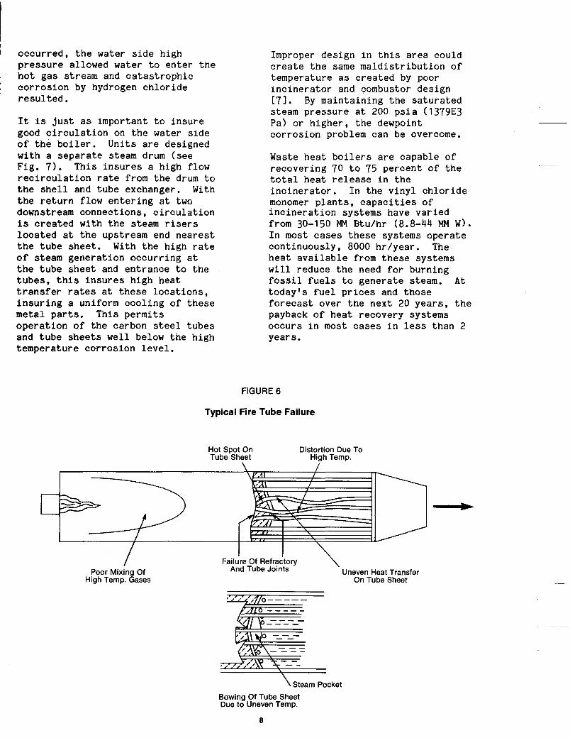
occurred, the water s ide high pressure allowed water t o enter the hot gas stream and catastrophic corrosion by hydrogen chloride resu l ted .
It is j u s t a s important t o insure good c i rcu la t ion on the water s ide of t he bo i l e r . U n i t s are designed w i t h a separate steam drum (see Fig. 7). This insures a h igh flow rec i rcu la t ion r a t e from t h e drum t o the s h e l l and t u b e exchanger. With the r e t u r n flow enter ing a t two downstream connections, c i rcu la t ion is created with the steam risers located a t t he upstream end nearest the t u b e sheet. With the h igh r a t e of steam generation occurring a t t h e t u b e sheet and entrance t o the t u b e s , t h i s i n s u r e s high heat t r ans fe r r a t e s a t these locat ions, insuring a uniform cooling of these metal par t s . This pe rmi t s operation of the carbon s t e e l tubes and t u b e sheets well below the h igh temperature corrosion level .
Improper design i n t h i s area could c rea te the same maldistribution of temperature a s created by poor incinerator and combustor design 171. By maintaining the saturated steam pressure a t 200 psia (1379E3 Pa) or higher, the dewpoint corrosion problem can be overcome.
Waste heat bo i l e r s are capable of recovering 70 t o 75 percent of the t o t a l heat re lease i n the incinerator . I n t he v i n y l chloride monomer p lan ts , capac i t ies of incinerat ion systems have varied from 30-150 MM B tu /h r (8.8-44 MM W ) . I n most cases these systems operate continuously, 8000 hr/year. The heat avai lable from these sys t ems w i l l reduce the need for b u r n i n g f o s s i l fue l s t o generate steam. A t today's fue l pr ices and those forecast over the next 20 years , t h e payback of heat recovery systems occurs i n most cases i n l e s s than 2 years.
FIGURE 6
Typical Fire Tube Failure
Hot Spot On Tube Sheet High Temp.
Distortion Due To
\
I Poor Mixin Of
High Temp. Eases Uneven Heat Transfer
On Tube Sheet
Failure Of Refractory \ And Tube Joints
\Steam Pocket Bowing Of Tube Sheet Due to Uneven Temp.
8

Mr. J. P. Grace of W. R. Grace expects that energy will come close to the prices below 183:
TABLE 2
Oil Gas Oil Gas $/BBL $IMCF $/MM Btu $/MM Btu - _ _
1950 1960 1970 1980 1985 low
medium high
1990 low medium high
2.51 0.06 0.43 0.06 2.88 0.14 0.50 0.1 4 3.15 0.17 0.54 0.1 7
27.00 1.70 4.66 1.70 42.50 5.25 7.33 5.25 55.00 6.25 9.48 6.25 80.00 8.50 13.79 8.50 60.00 12.50 10.34 12.50 89.50 15.50 15.43 15.50
135.00 23.00 23.28 23.00
*$/BBL X 6.29 = $/M3 $/MCF X .0353 = $/M3
$/MM Btu X 9.478E-10 = $/J
Besides the advantage of generating steam, the waste heat boiler serves as a primary cooler for the hot incinerator gases. Temperatures leave the boiler in the range of 500-700 F (260-370 C). This reduces
the water load on the system necessary to quench and scrub the gases of HCI. In many areas where the VCM plants are located, water usage is restricted. By cooling the gases from 2600-600 F (1425-315 C> using a waste heat boiler, the water requirements for cooling are reduced almost 85 percent.
TABLE 3 Flue Gas Composition
Vol. Percent
Oxygen Nitrogen
2.6 65.8
Carbon Dioxide 14.4 Water 7.5 Hydrogen Chloride 9.7 Chlorine 485 ppm
Typical composition of gases leaving incinerator chamber and boiler exhaust.
FIGURE 7
Fire Tube Heat Exchanger Waste Heat Boiler
High Temp. Gases
1600°F - 2600°F 870°C - 1427°C
9

By-product Recovery Systems Combustion p roduc t s from t h e i n c i n e r a t i o n system a r e a s shown i n Tab le 3.
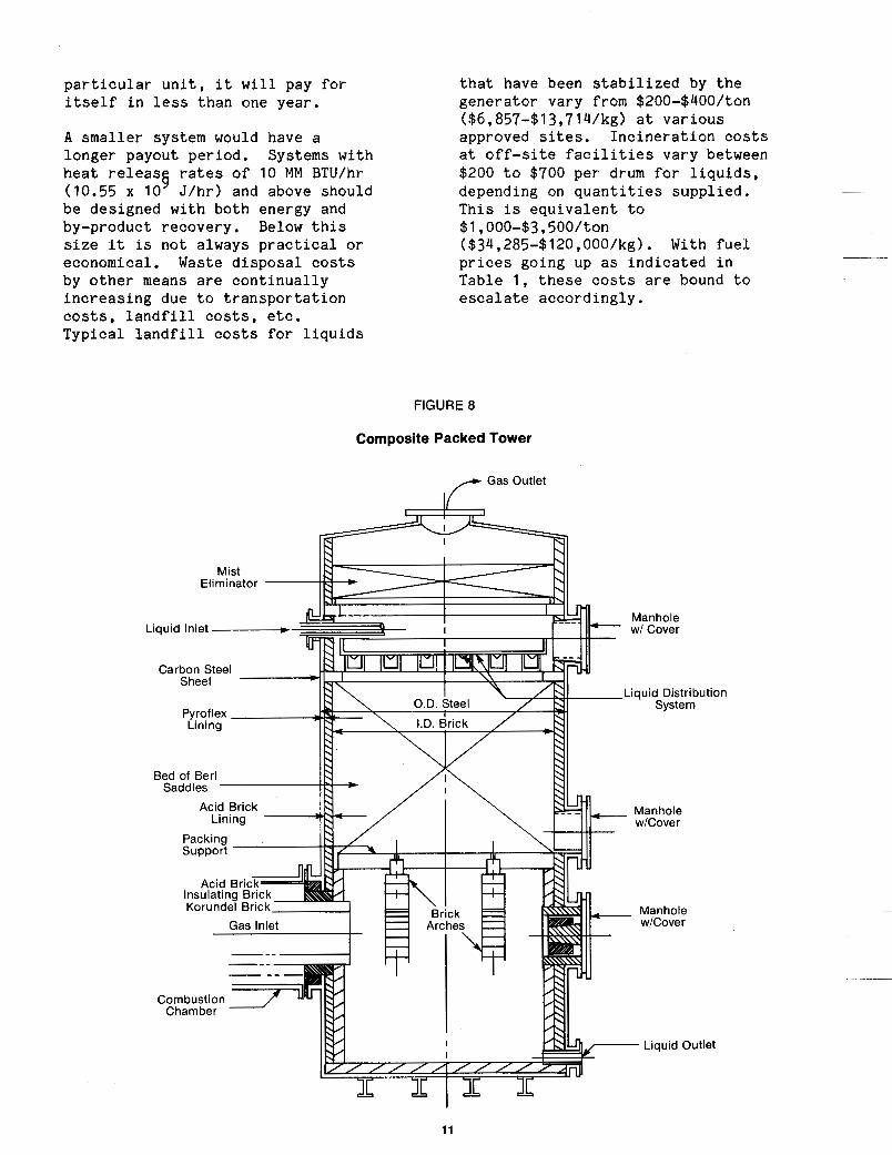
The q u a n t i t y o f hydrogen chloride r e s u l t i n g from t h e combustion o f waste c h l o r i n a t e d l i q u i d s and g a s e s i s a f a i r pe rcen tage of t h e t o t a l p roduc t s . The major p roduc t s are n i t r o g e n and water vapor. S ince HCI i s r e a d i l y absorbed i n water, it becomes economical t o add the necessa ry quench and a b s o r p t i o n u n i t t o produce a c i d up t o a e z o t r o p i c (18-20 p e r c e n t ) c o n c e n t r a t i o n . Experience has been ga ined i n t h e des ign and o p e r a t i o n of these a b s o r b e r s (see Fig . 8 ) . Major h u r d l e s had t o be overcome i n t h e proper material s e l e c t i o n t o minimize t h e c o r r o s i o n problems i n h e r e n t w i t h t h e hot-cold i n t e r f a c e , s u p p o r t g r i d s for tower pack ing , and wal l c o n s t r u c t i o n t o s t a n d both t empera tu re and c o r r o s i o n .
Systems have been s u p p l i e d t o produce a c i d s a t c o n c e n t r a t i o n s up t o 100 p e r c e n t anhydrous HC1 (see F i g . 9 , I O ) . I n a l l c a s e s t h e e f f i c i e n c y of these by-product a c i d r ecove ry sys tems i s dependent upon the e f f i c i e n c y e x i s t i n g i n t h e combustion system. A good q u a l i t y a c i d i s soot-free ( less than 10 ppm o r g a n i c s ) and c o n t a i n s less than 100 ppm of free c h l o r i n e . I n o r d e r t o p rov ide t h i s , it i s impor t an t t h a t the combustor i n t he i n c i n e r a t i o n system comple te ly o x i d i z e t h e o r g a n i c s i n t h e was te , and a t t h e same time, produce a s low a c h l o r i n e c o n t e n t a s p o s s i b l e . A s shown above, i t is impor t an t t o minimize excess a i r t o ma in ta in low c h l o r i n e l e v e l s , and a t t h e same time, produce low o r g a n i c (hydrocarbons) l e v e l s i n t he exhaus t g a s e s [ 9 , 101.
I n o r d e r t o minimize o p e r a t i n g costs of a t y p i c a l was te d i s p o s a l system, i t is w e l l t o rev iew t h e amount of caust ic r e q u i r e d i n the t a i l s sc rubb ing tower. T h i s tower is needed to s c r u b t h e HC.l t h a t l e a v e s t h e quench-absorber system, a s well
a s t he f r e e c h l o r i n e t h a t h a s been produced. The quench-absorber (pr imary s c r u b b e r ) m u s t remove a s much H C I a s i s economical ly p o s s i b l e . Many towers a r e unders ized and a s a r e s u l t a h igh volume of H C I b r e a k s through. Proper packing h e i g h t , packing , s i z i n g , and s e l e c t i o n w i l l r educe t h e H C I b reak th rough , u t i l i z e t h e water f o r sc rubbing most e f f e c t i v e l y , and minimize t h e need for c a u s t i c i n t h e f i n a l s c rubb ing tower. Othe r impor t an t c o n s i d e r a t i o n s i n t h e pr imary tower des ign a r e water vapor c o n c e n t r a t i o n of t h e i n l e t g a s e s , t empera tu re of t h e i n l e t g a s e s and t h e i n l e t t empera tu re o f t h e sc rubb ing water. Each w i l l have an e f fec t on t h e s i z e of t h e tower [ I l l . The a d d i t i o n of a waste h e a t b o i l e r upstream has t h e advantage of r educ ing water vapor c o n t e n t of g a s e s a s well a s r e d u c t i o n of tempera ture . Tne f i n a l s c rubb ing tower i s needed t o produce f i n a l e f f l u e n t g a s e s t o t h e atmosphere w i t h chlorine less than 5 ppm and hydrogen c h l o r i d e a t less than 10 ppm. The f i n a l tower is normally c o n s t r u c t e d from f iber r e i n f o r c e d p l a s t i c s (FRP m a t e r i a l s ) since t h e i n l e t tempera ture is reduced t o l e v e l s below 200 F (93 C ) .
Economics of Energy Recovery and By-product Recovery Tne example shown i n Table 4 l i s ts the waste q u a n t i t i e s t y p i c a l i n a v i n y l c h l o r i d e monomer p l a n t . Also l i s t e d a r e the u t i l i t y r equ i r emen t s for t h e i n c i n e r a t i o n system, a s well a s t h a t r e q u i r e d f o r t h e quench, a b s o r b e r , and scrubber. Note t h a t t h e costs i n d i c a t e d for steam and a c i d produced a r e t y p i c a l . Values which a r e most common to t h e p a r t i c u l a r p l a n t s i t e may be i n s e r t e d . T h i s should a lso i n c l u d e u t i l i t y cost , l a b o r c o s t , e tc . I n t h e example, no te t h e s a v i n g s t h a t can resul t by t h e a d d i t i o n of t h e energy recovery and ac id recovery systems. These w i l l pay for the o p e r a t i o n of the waste d i s p o s a l system and return money to the p l a n t . Due t o t h e s i z e of t h i s
10
p a r t i c u l a r u n i t , it w i l l pay for i t s e l f i n l e s s t h a n one yea r .
A s m a l l e r system would have a longe r payout pe r iod . Systems wi th hea t r e l e a s g r a t e s of 10 MM BTU/hr (10.55 x 10 J /hr) and above should be des igned wi th both energy and by-product recovery . Below t h i s s ize it i s n o t a lways p r a c t i c a l or economical . Waste d i s p o s a l costs by other means are c o n t i n u a l l y i n c r e a s i n g due t o t r a n s p o r t a t i o n costs , l a n d f i l l costs , e tc . T y p i c a l l a n d f i l l costs for l i q u i d s
t h a t have been s t a b i l i z e d by t h e g e n e r a t o r vary from $200-$400/ton ($6,857-$13,714/kg) a t v a r i o u s approved s i tes . I n c i n e r a t i o n costs a t off-s i te f a c i l i t i e s va ry between $200 t o $700 p e r drum for l i q u i d s , depending on q u a n t i t i e s s u p p l i e d . T h i s is e q u i v a l e n t t o $1,000-$3,500/ton ($34,285-$120,000/kg). With f u e l p r i c e s going up as i n d i c a t e d i n Tab le 1 , these costs are bound t o e s c a l a t e acco rd ing ly .
FIGURE 8
Composite Packed Tower
Liquid Inlet -
11
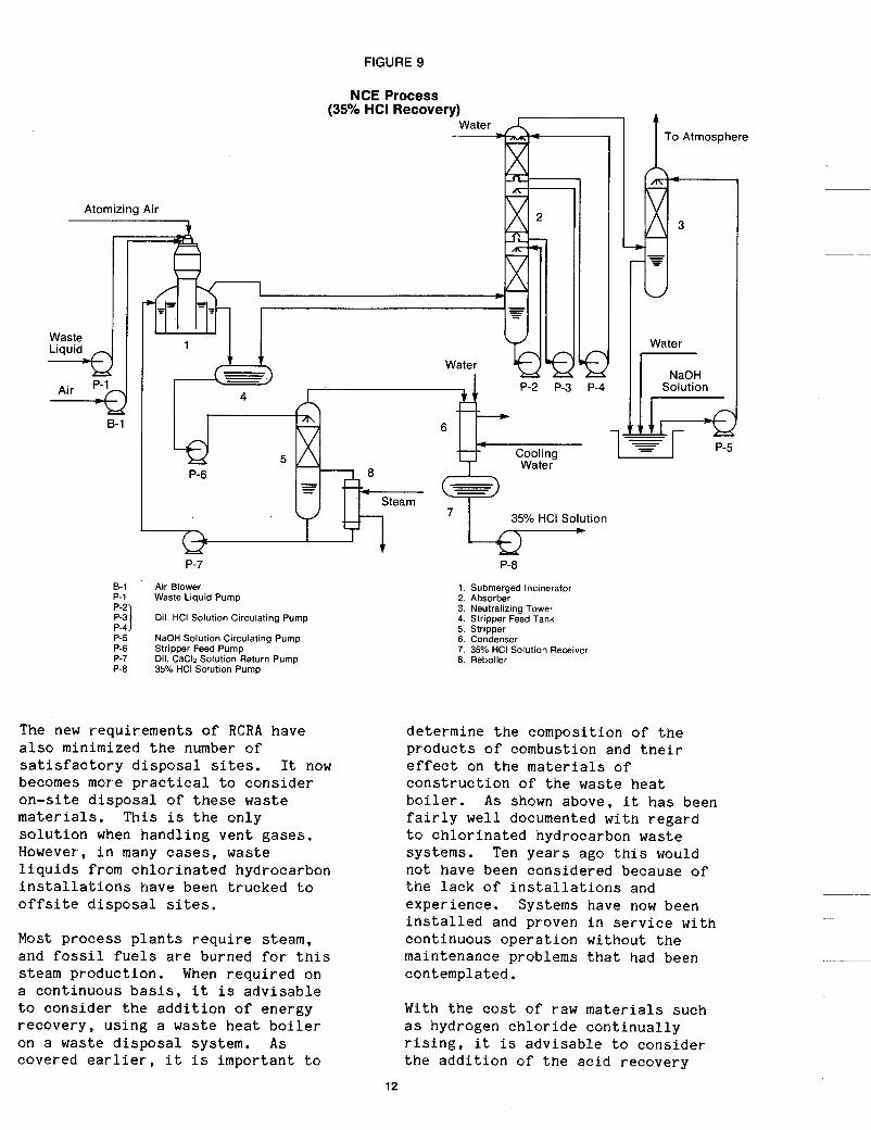
FIGURE 9
NCE Process (35% HCI Recovery)
Water
Atomizing Air M,
Waste
B-1
c
I
P-3 P-4
1
P-7 P-8
8-1 Air Blower P-1 Waste Liquid Pump P-2 p-31 P-4 P-5 NaOH Solution Circulating Pump P-6 Stripper Feed Pump P-7 Dil. CaC12 Solution Return Pump P-8 35% HCI Solution Pump
Dil. HCI Solution Circulating Pump
The new requ i r emen t s of RCRA have a l s o minimized t h e number of s a t i s f a c t o r y d i s p o s a l s i tes. It now becomes more p r a c t i c a l t o c o n s i d e r o n - s i t e d i s p o s a l of these was te m a t e r i a l s . T h i s i s t h e o n l y s o l u t i o n when h a n d l i n g v e n t gases . However, i n many c a s e s , waste l i q u i d s from c h l o r i n a t e d hydrocarbon i n s t a l l a t i o n s have been t r u c k e d t o o f f s i t e d i s p o s a l s i tes .
Most p r o c e s s p l a n t s r e q u i r e s team, and fos s i l f u e l s a r e burned for t h i s s team p roduc t ion . When r e q u i r e d on a con t inuous b a s i s , i t i s a d v i s a b l e t o c o n s i d e r the a d d i t i o n of ene rgy r e c o v e r y , u s i n g a waste h e a t boiler on a waste d i s p o s a l system. As covered ear l ier , i t i s impor t an t t o
1. Submerged Incinerator 2. Absorber 3. Neutralizing Tower 4. Stripper Feed Tank 5. Stripper 6. Condenser 7. 35% HCI Solution Receiver 8. Reboiler
To Atmosphere I . . 4. Water
Solution
de te rmine the composi t ion of t he p r o d u c t s of combustion and t h e i r effect on t h e m a t e r i a l s of c o n s t r u c t i o n of t h e was te heat b o i l e r . As shown above, it h a s been f a i r l y well documented w i t h r e g a r d t o c h l o r i n a t e d hydrocarbon waste sys tems. Ten y e a r s ago t h i s would no t have been cons ide red because of t h e l a c k of i n s t a l l a t i o n s and expe r i ence . Systems have now been i n s t a l l e d and proven i n s e r v i c e w i t h con t inuous o p e r a t i o n w i t h o u t t h e maintenance problems t h a t had been contempla ted .
With the cost of raw m a t e r i a l s such a s hydrogen c h l o r i d e c o n t i n u a l l y r i s i n g , it i s a d v i s a b l e t o c o n s i d e r t h e a d d i t i o n of t h e a c i d r ecove ry
12

FIGURE 10
UCAR Process Anhydrous HCI
Clorinated Organic Waste
L
Quench Acid
(Recycle)
Filter
% I-
Fresh Water Or Weak Acid From Vent Scrubber
Clean Gas To Atmosphere 4 (3 - 50 ppm. HCI)
Water Or Caustic Solution Tertiary
Absorber
I I I Blower To Sewer Or Absorption Train
Secondary Condenser Condenser
C.W. Brine
C.W. Brine (OF.)
Anhydrous HCI
8
system i n these waste d i s p o s a l p l a n t s . As seen from t h e example, t h e hydrogen chlor ide recovery more t h a n b a l a n c e s o u t t h e t o t a l o p e r a t i n g c o s t s o f the p l a n t .
T h i s , of c o u r s e , h a s been based on the v a l u e o f hydrogeg chloride a t 0.20851gal ($54.95/M 1. It i s i m p o r t a n t t o review t h e economics of a p a r t i c u l a r s i t u a t i o n . This , of course, w i l l h e l p t o determine the need f o r t he a d d i t i o n a l equipment. These systems have been i n s t a l l e d and a r e now o p e r a t i n g , and have been proven i n s e r v i c e . Now it is r e a l l y up t o the i n d i v i d u a l p l a n t s i t e s and t he i r needs for energy r e c o v e r y and by-product product ion to de termine whether these a d d i t i o n s can be j u s t i f i e d . From an economic s t a n d p o i n t , n o t e t h a t t h e y w i l l
Acid
Packed-Column
I
21% HCI
4
c e r t a i n l y cover t h e cost o f d i s p o s a l and a l l o w t h e waste d i s p o s a l end o f the p l a n t t o be a p r o f i t center for the o p e r a t i o n , r a t h e r t h a n an o p e r a t i n g expense w i t h no r e t u r n . Waste d i s p o s a l systems can be p r o f i t a b l e i f designed and i n s t a l l e d wi th t o t a l economics inc luded i n t h e f a c i l i t y d e s i g n .
. Hz0)
13

TABLE 4 Example of Vinyl Chloride Waste
Disposal System
Specifications
Wastes - A. 11,250 Ib/hr Max. Waste Tars (5,103 kg/hr) 3,400 Ib/hr Norm. @? 50 psig (1,542 kg/hr @ 345E3 Pa)
B. 21,545 Ib/hr Max. Vent Gases (9,773 kg/hr) (202,400 SCFH) @? (5,731 kg/hr @? 21 .E3 Pa)
Thermal Oxidizer Rating
Combustion Air
70 x IO6 Btu/hr (73.854 x IO9 J/hr)
12,500 SCFM @? 75 in. W.C. (5.9 M3/Sec @? 1.905 m - 223 kW) 300 hp
3,400 Ib/hr @? 175 psig (1,542 kg/ hr @ 1.206E6 Pa)
0 to 20 gpm @ 40 psig (0 - 1.26E3 M3/sec @ 2.75E5 Pa)
0 to 25,000 SCFH @? 4 psig (0 - 708M3/hr @? 2.75E4 Pa)
Atomizing Steam
Cooling Water
Natural Gas
Waste Heat Boiler
Inlet Gases
Steam Produced
2,200 F, 10.4 percent HCI, 13.6
52,470 Ib/hr @? 180 psig (23,800
5,830 Ib/hr @? 215 F (2,645 kg/hr
percent HzO (1,204 C)
kg/hr @? 1,260E3 Pa)
Blowdown @? 102 C))
Hydrogen Chloride Recovery Tower
Water Flow
Acid Produced
340 gpm @? 40 psig - 60 F (2.145E-2 MYsec @ 2.75E5 Pa 15 C) 100 gpm - 15 percent (6.31E- 3M3/sec)
Caustic Scrubbing Tower Scrubbing Liquor
Discharge
Recycle Pump
1,650 Ib/hr 10 percent NaOH
1,650 Ib/hr 14 percent Salts
10 hp (7.46 kW)
(748 kglhr)
(748 kg/ hr)
Operating Costs
Utility Costs Interest, Maintenance Costs, Etc. Item Unit Cost Consumption Cost$/hr
Interest Rate = 15 percent of total installed cost. Steam $5/1,000 Ib 3400 Ib/hr $17.00 Maintenance = 3 percent of total installed cost.
($0.01 l/kg) (1 542 kg/hr) Other Expenses = 3 percent of total installed cost.
Pure $0.541/1,000 gal 110 gpm $ 3.57 Total = $2,500,000 x 0.21 x 1/8,000 = $65.62 hr Water ($0.143/M3) (6.94E-3M3/sec)
Cooling $0.066/1,000 gal 250 gpm $ 1.00 Water ($0.01 74/M3) (1 5.775E-3M31sec)
Elec. $0.04/kW 310 hp Power (230 kW) Summary of Operating Costs
$ 9.25
Utilitv Costs Labor Costs Depreciation Interest, Maintenance, Etc.
Caustic $0.06/lb 165 Ib/hr $ 9.90 ($0.1 323/kg) (74.84 kglhr)
Total
Installation Cost
$40.72 Total Operating Costs per hr
Equipment Cost x 2.5 = $2,500,000.00 (Includes Foundations, Site Preparation, Structural, Piping, Electrical, etc.)
2.5 persons = 0.5 person per shift x 3 shifts and 1 person Average Annual Wage - $20,000 Overhead - 150 percent Hourly Cost = 2.5 x 20,000 x 2.5 + 8000 = $15.63/hr
Labor Cost
Depreciation
Installed Cost depreciated over 7 year period - $2,500,000 x 0.9 x 1/7 x 1/8,000 = $40.18/hr
$ 40.72 $ 15.63 $ 40.18 $ 65.62 $162.15/hr
Summary of Recovery Options
Steam Generation 52,470 Ib/hr @? $5/1,000 Ib = $262.35/hr (23,800 kg/hr @? $.01 l/kg)
Hydrogen Chloride Recovery 100 gpm of 15 percent HCL @? 0.208/gal. = $187.50/hr (6.32E-3M3/sec) ($54.95/M3)
Total Recovery $449.85/hr
14
References
[11
c21
[31
C41
[ 51
161
[7 1
181
191
[lo1
Environmental Protection Agency, Resource Conservation & Recovery Act, Federal Register, Jan. 23, 1981. Current Developments, llEnvironmental Reports , Bureau of National Affairs , Inc. , p. 2273 (4-20-79). Santo ler i , J . J . , llChlorinated Hydrocarbon Waste Disposal and Recovery
~
Systems,11- Chemical Engineering Progress, Vol. 69, No. 1 , Jan. 1973. Neumann, K. K . , "Studies on the Thermodynamics of Decomposition and Incineration of Chlorine-Containing Residues , I 1 Dechema-Monograph, 80 (1616-1638). 319-331 (1976) . Kiang, Y . H . , "Chlorinated Hydrocarbon Emission Control,11 APCA 72s t Annual Mtg., June 1978. Fassler , K . , Leib, H . , and Spahn, H . , llCorrosion i n Refuse Incineration Plants,11 Mitteilugnen der VGB, 40(2) , 126-139 (1968). Hung, W . , " R e s u l t s of a Firetube Test Boiler i n Flue Gas w i t h Hydrogen Chloride and F l y Ash," ASME Winter Annual Mtg., Nov. 1975. Grace, J . P . , "Energy and the Economy," 8 t h Annual Energy Technology Conference, Washington, D.C. , March 1981. H u l s w i t t , C . , llSolving Waste Problems Profi tably," Chem.
Mitachi, K . , e t a l . , "Treatment of L i q u i d Waste Derived from Chlorinated Hydrocarbon Plants . I 1
Oldershaw, C. F. , Simenson, L. , Brown, T . , and Radcliffe, F. , llAbsorption and Purif icat ion of Hydrogen Chloride from Chlorination of
- Wk. 6-14-69. L_
Hydrocarbons," Chem. Eng. Progress, Vol. 43, NO. 7 , PP. 371 -378.
Key Words: Chlorine, Combustion, Economics, Hazardous, Incinerator , Resource, Waste Heat
15


i i

12/82