Optimizing Moderators and Shielding In a Neutron-Pulsing...
18
Optimizing Moderators and Shielding In a Neutron-Pulsing Delayed Gamma Experiment Part I Robert Crabbs 1-12-2009
Transcript of Optimizing Moderators and Shielding In a Neutron-Pulsing...
Optimizing Moderators and Shielding
In a Neutron-Pulsing Delayed Gamma Experiment
Part I
Robert Crabbs
1-12-2009
INTRODUCTION
For the past several months, we have simulated an experiment which measures delayed gamma
emissions to determine the fissile composition of a sample. The measurements occur in 10.12 s cycles,
with a 100ms irradiation time, a 20ms cool-off, and a 10 s counting period. Neutrons are created by a
2.5 MeV D-D neutron generator with a strength of 1E8 neutrons per second. To increase the
measurement sensitivity, we tailor the source spectrum with a layer of moderating material between
the generator and the irradiation cavity containing the sample. This creates a flux of thermal neutrons
which cause fissions within the target. Two HPGe detectors within the cavity then register the gamma
rays released by the fission products created.
Recent calculations of fission rates in our proposed experimental geometry have shown some rather
disappointing numbers. In light of the results, I double checked the simulations we completed earlier on
which we based our optimized geometry. I also systematically tested various aspects to further optimize
the thermal fissions rates in an HEU target.
Without any optimizations in place, we obtained the following results with the original design.
Sub-MeV/Fast Neutron Ratio at Target: 1.46941
Total Neutron Flux at Target: 9.15870E-05 (0.0113) 235
U Fission Probability: 8.09496E-06 (0.0147) 238
U Fission Probability: 3.03348E-08 (0.0153)
Total Neutron Flux at Detectors: 8.72953E-06 (0.0020)
Fast Neutron Flux at Detectors: 2.76449E-06 (0.0072)
The first set of MCNPX calculations were all very fast (about five minutes long), and therefore showed
poor statistical uncertainties. I then submitted much longer jobs on the Lawrencium computer cluster to
obtain better results. This write-up is based on the more precise results.
The HEU target remained constant between all the runs, as a single 1.50777 g cylindrical pin. This UO2
pin had a radius of 0.25 cm, a length of 0.7 cm, a mass density of 10.97 g/cm3, and a
235U enrichment of
43%.
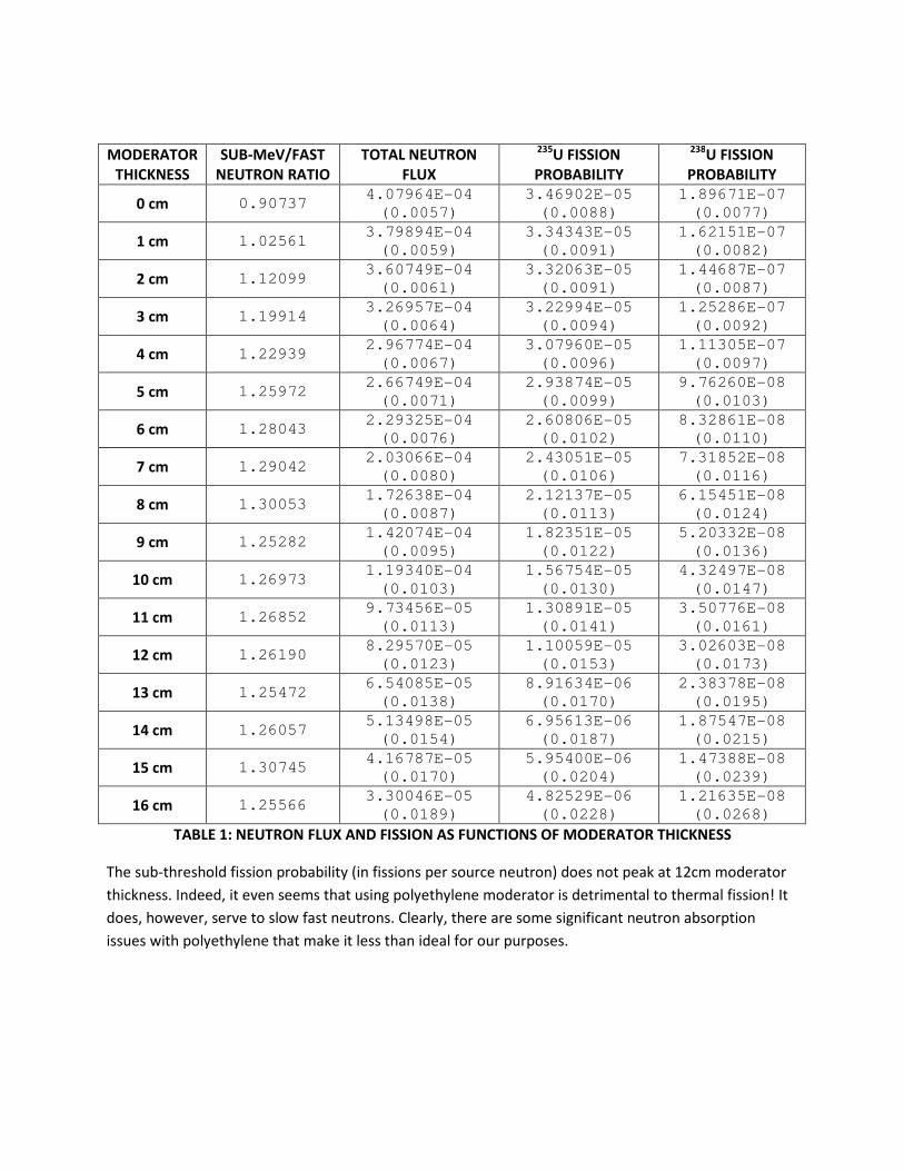
RESULTS: MODERATOR THICKNESS
As my first task, I verified original results pertaining to the optimum thickness of polyethylene
moderator around the neutron generator. Note that the previous calculations optimized for
combination of thermal/fast fission ratio and neutron flux. I have reported related quantities in Table 1
below.
Appendix A shows 2D projections of the experimental geometry used. This geometry is identical in
function to the one that Jeremy Lorenzo used for the initial optimizations. He found that a 12 cm
polyethylene thickness was best for maximizing the thermal/fast neutron ratio, while maintaining a high
total flux at the target. (A high thermal/fast neutron ratio improves differentiation between 235
U and 238
U fissions, while total neutron flux relates to the strength of the delayed-gamma signal.)
For calculating thermal to fast neutron flux ratios, “thermal” neutrons are any which have energy below
the 238U fission threshold (nearly 1 MeV). Fast neutrons, then, have energy greater than 1 MeV. Note
that the flux has units of neutrons/cm2/source neutron, and is tallied over the surface area of the target
(1.49 cm2).
Relative uncertainties are given in parentheses. The longer simulations tracked 2.5E8 source particles,
which kept uncertainties under 3%.
MODERATOR
THICKNESS
SUB-MeV/FAST
NEUTRON RATIO
TOTAL NEUTRON
FLUX
235U FISSION
PROBABILITY
238U FISSION
PROBABILITY
0 cm 0.90737 4.07964E-04
(0.0057)
3.46902E-05
(0.0088)
1.89671E-07
(0.0077)
1 cm 1.02561 3.79894E-04
(0.0059)
3.34343E-05
(0.0091)
1.62151E-07
(0.0082)
2 cm 1.12099 3.60749E-04
(0.0061)
3.32063E-05
(0.0091)
1.44687E-07
(0.0087)
3 cm 1.19914 3.26957E-04
(0.0064)
3.22994E-05
(0.0094)
1.25286E-07
(0.0092)
4 cm 1.22939 2.96774E-04
(0.0067)
3.07960E-05
(0.0096)
1.11305E-07
(0.0097)
5 cm 1.25972 2.66749E-04
(0.0071)
2.93874E-05
(0.0099)
9.76260E-08
(0.0103)
6 cm 1.28043 2.29325E-04
(0.0076)
2.60806E-05
(0.0102)
8.32861E-08
(0.0110)
7 cm 1.29042 2.03066E-04
(0.0080)
2.43051E-05
(0.0106)
7.31852E-08
(0.0116)
8 cm 1.30053 1.72638E-04
(0.0087)
2.12137E-05
(0.0113)
6.15451E-08
(0.0124)
9 cm 1.25282 1.42074E-04
(0.0095)
1.82351E-05
(0.0122)
5.20332E-08
(0.0136)
10 cm 1.26973 1.19340E-04
(0.0103)
1.56754E-05
(0.0130)
4.32497E-08
(0.0147)
11 cm 1.26852 9.73456E-05
(0.0113)
1.30891E-05
(0.0141)
3.50776E-08
(0.0161)
12 cm 1.26190 8.29570E-05
(0.0123)
1.10059E-05
(0.0153)
3.02603E-08
(0.0173)
13 cm 1.25472 6.54085E-05
(0.0138)
8.91634E-06
(0.0170)
2.38378E-08
(0.0195)
14 cm 1.26057 5.13498E-05
(0.0154)
6.95613E-06
(0.0187)
1.87547E-08
(0.0215)
15 cm 1.30745 4.16787E-05
(0.0170)
5.95400E-06
(0.0204)
1.47388E-08
(0.0239)
16 cm 1.25566 3.30046E-05
(0.0189)
4.82529E-06
(0.0228)
1.21635E-08
(0.0268)
TABLE 1: NEUTRON FLUX AND FISSION AS FUNCTIONS OF MODERATOR THICKNESS
The sub-threshold fission probability (in fissions per source neutron) does not peak at 12cm moderator
thickness. Indeed, it even seems that using polyethylene moderator is detrimental to thermal fission! It
does, however, serve to slow fast neutrons. Clearly, there are some significant neutron absorption
issues with polyethylene that make it less than ideal for our purposes.
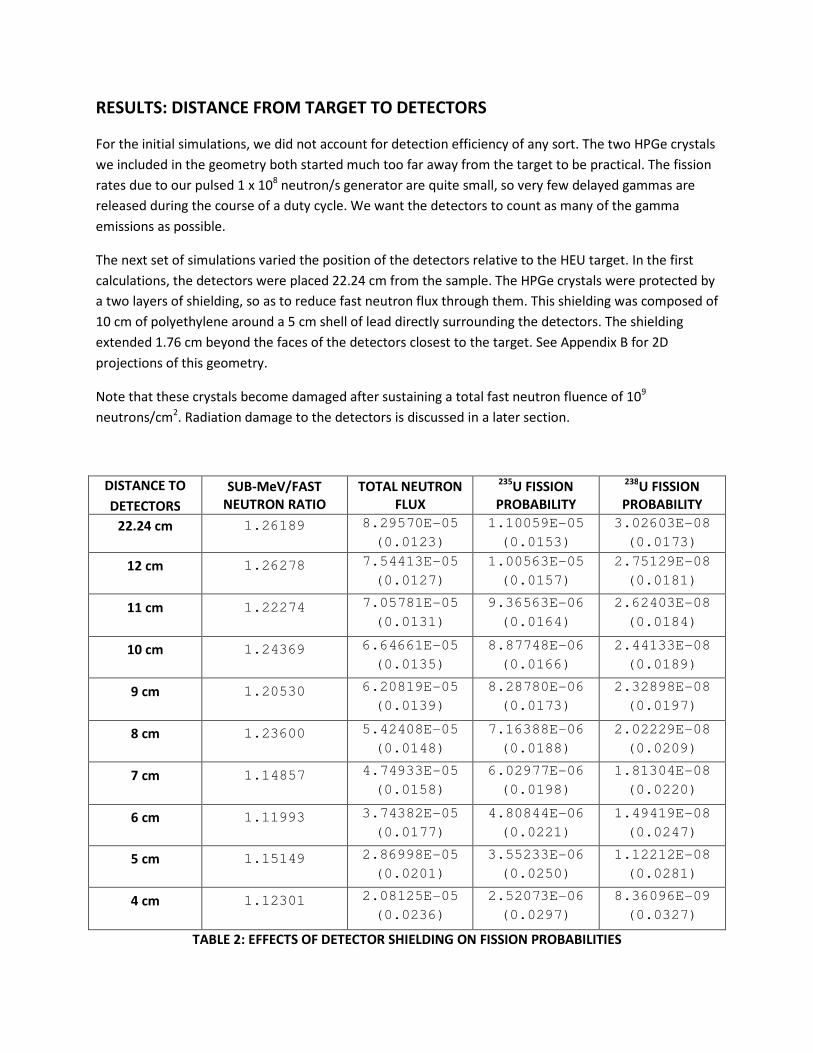
RESULTS: DISTANCE FROM TARGET TO DETECTORS
For the initial simulations, we did not account for detection efficiency of any sort. The two HPGe crystals
we included in the geometry both started much too far away from the target to be practical. The fission
rates due to our pulsed 1 x 10⁸ neutron/s generator are quite small, so very few delayed gammas are
released during the course of a duty cycle. We want the detectors to count as many of the gamma
emissions as possible.
The next set of simulations varied the position of the detectors relative to the HEU target. In the first
calculations, the detectors were placed 22.24 cm from the sample. The HPGe crystals were protected by
a two layers of shielding, so as to reduce fast neutron flux through them. This shielding was composed of
10 cm of polyethylene around a 5 cm shell of lead directly surrounding the detectors. The shielding
extended 1.76 cm beyond the faces of the detectors closest to the target. See Appendix B for 2D
projections of this geometry.
Note that these crystals become damaged after sustaining a total fast neutron fluence of 109
neutrons/cm2. Radiation damage to the detectors is discussed in a later section.
DISTANCE TO
DETECTORS
SUB-MeV/FAST
NEUTRON RATIO
TOTAL NEUTRON
FLUX
235U FISSION
PROBABILITY
238U FISSION
PROBABILITY
22.24 cm 1.26189 8.29570E-05
(0.0123)
1.10059E-05
(0.0153)
3.02603E-08
(0.0173)
12 cm 1.26278 7.54413E-05
(0.0127)
1.00563E-05
(0.0157)
2.75129E-08
(0.0181)
11 cm 1.22274 7.05781E-05
(0.0131)
9.36563E-06
(0.0164)
2.62403E-08
(0.0184)
10 cm 1.24369 6.64661E-05
(0.0135)
8.87748E-06
(0.0166)
2.44133E-08
(0.0189)
9 cm 1.20530 6.20819E-05
(0.0139)
8.28780E-06
(0.0173)
2.32898E-08
(0.0197)
8 cm 1.23600 5.42408E-05
(0.0148)
7.16388E-06
(0.0188)
2.02229E-08
(0.0209)
7 cm 1.14857 4.74933E-05
(0.0158)
6.02977E-06
(0.0198)
1.81304E-08
(0.0220)
6 cm 1.11993 3.74382E-05
(0.0177)
4.80844E-06
(0.0221)
1.49419E-08
(0.0247)
5 cm 1.15149 2.86998E-05
(0.0201)
3.55233E-06
(0.0250)
1.12212E-08
(0.0281)
4 cm 1.12301 2.08125E-05
(0.0236)
2.52073E-06
(0.0297)
8.36096E-09
(0.0327)
TABLE 2: EFFECTS OF DETECTOR SHIELDING ON FISSION PROBABILITIES
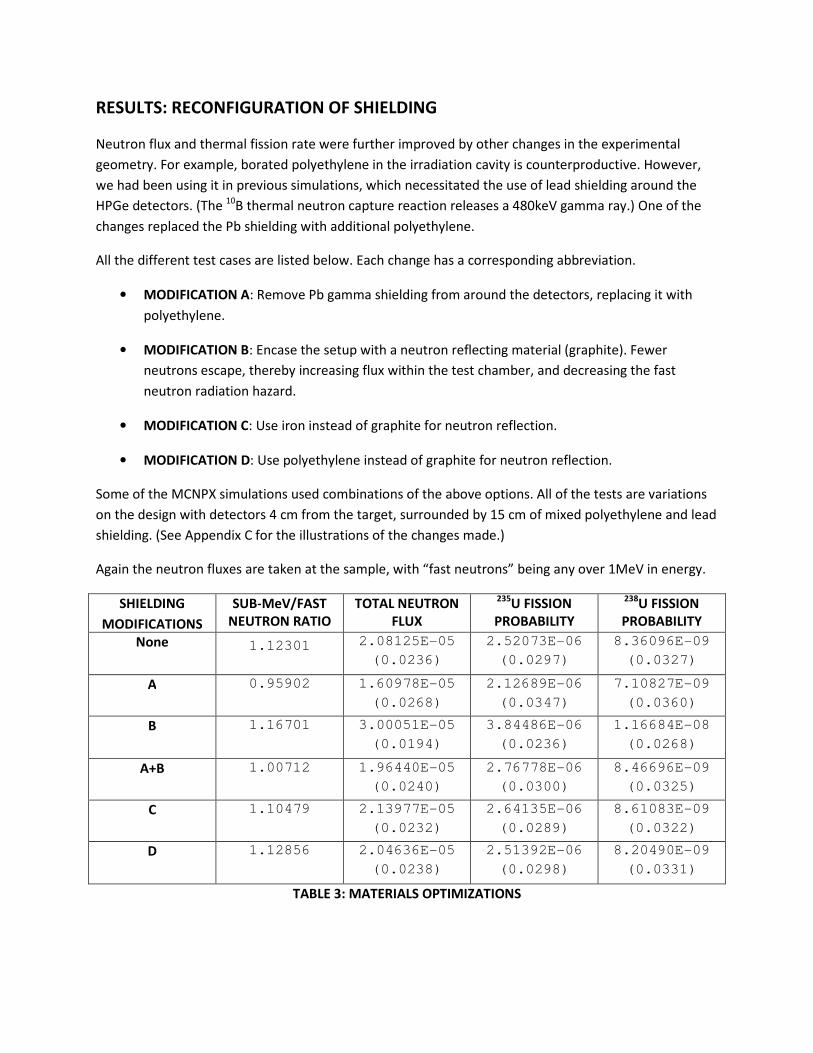
RESULTS: RECONFIGURATION OF SHIELDING
Neutron flux and thermal fission rate were further improved by other changes in the experimental
geometry. For example, borated polyethylene in the irradiation cavity is counterproductive. However,
we had been using it in previous simulations, which necessitated the use of lead shielding around the
HPGe detectors. (The 10
B thermal neutron capture reaction releases a 480keV gamma ray.) One of the
changes replaced the Pb shielding with additional polyethylene.
All the different test cases are listed below. Each change has a corresponding abbreviation.
• MODIFICATION A: Remove Pb gamma shielding from around the detectors, replacing it with
polyethylene.
• MODIFICATION B: Encase the setup with a neutron reflecting material (graphite). Fewer
neutrons escape, thereby increasing flux within the test chamber, and decreasing the fast
neutron radiation hazard.
• MODIFICATION C: Use iron instead of graphite for neutron reflection.
• MODIFICATION D: Use polyethylene instead of graphite for neutron reflection.
Some of the MCNPX simulations used combinations of the above options. All of the tests are variations
on the design with detectors 4 cm from the target, surrounded by 15 cm of mixed polyethylene and lead
shielding. (See Appendix C for the illustrations of the changes made.)
Again the neutron fluxes are taken at the sample, with “fast neutrons” being any over 1MeV in energy.
SHIELDING
MODIFICATIONS
SUB-MeV/FAST
NEUTRON RATIO
TOTAL NEUTRON
FLUX
235U FISSION
PROBABILITY
238U FISSION
PROBABILITY
None 1.12301 2.08125E-05
(0.0236)
2.52073E-06
(0.0297)
8.36096E-09
(0.0327)
A 0.95902 1.60978E-05
(0.0268)
2.12689E-06
(0.0347)
7.10827E-09
(0.0360)
B 1.16701 3.00051E-05
(0.0194)
3.84486E-06
(0.0236)
1.16684E-08
(0.0268)
A+B 1.00712 1.96440E-05
(0.0240)
2.76778E-06
(0.0300)
8.46696E-09
(0.0325)
C 1.10479 2.13977E-05
(0.0232)
2.64135E-06
(0.0289)
8.61083E-09
(0.0322)
D 1.12856 2.04636E-05
(0.0238)
2.51392E-06
(0.0298)
8.20490E-09
(0.0331)
TABLE 3: MATERIALS OPTIMIZATIONS
RESULTS: DISTANCE FROM NEUTRON GENERATOR TO TARGET
The previous sections show that the presence of excess polyethylene is detrimental to neutron fluxes
and fission probabilities in the target. Polyethylene moderates fast neutrons, making them more likely
to cause fissions. However, polyethylene contains light hydrogen nuclei, which tend to absorb neutrons.
Thus, there are two competing effects in our spectrum-tailoring assembly. We want to minimize the
neutron absorption, while also creating a sufficient thermal neutron flux at the target.
In addition, neutrons produced in the D-D generator are emitted more or less isotropically. Therefore,
the flux through the target can be maximized by minimizing the distance between source and target.
Naturally, this distance must be at least as large as the thickness of the moderator used.
However, we also need to consider the radiation effects of fast neutrons on the detectors. We placed
additional polyethylene around the HPGe crystals to minimize radiation damage. This shielding put the
target/detector plane farther from the source.
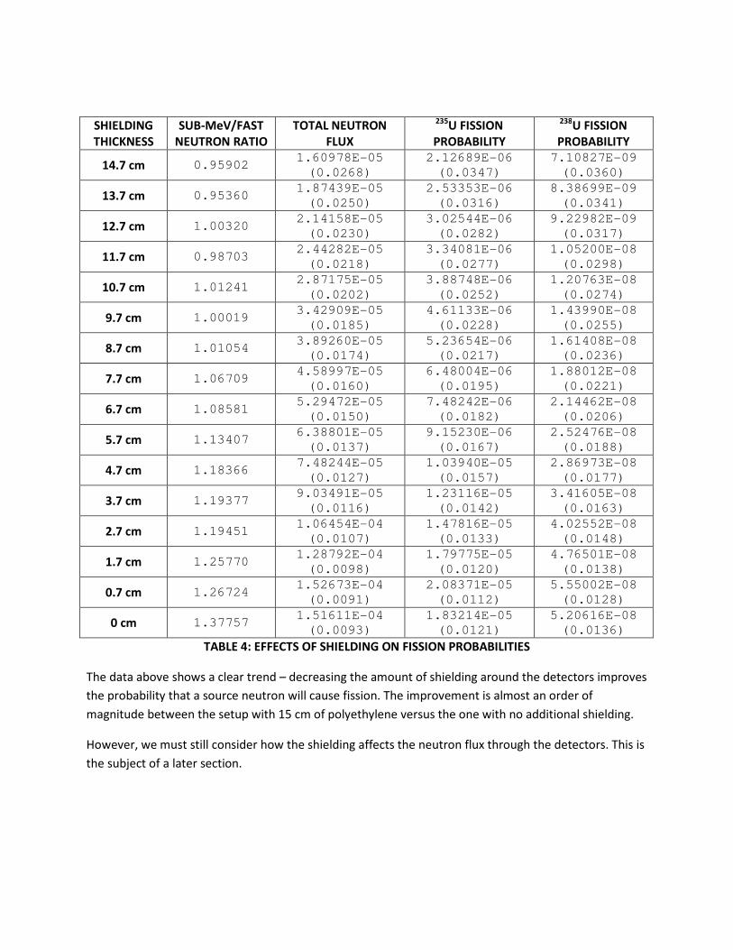
Table 4 gives the results of another series of simulations, for which the thickness of shielding was
reduced incrementally from 15 cm to 0 cm. The crystals are each 4 cm from the target. The lead
shielding was also replaced with polyethylene (material option A in the previous section). See Appendix
D for a figure depicting the geometry.
SHIELDING
THICKNESS
SUB-MeV/FAST
NEUTRON RATIO
TOTAL NEUTRON
FLUX
235U FISSION
PROBABILITY
238U FISSION
PROBABILITY
14.7 cm 0.95902 1.60978E-05
(0.0268)
2.12689E-06
(0.0347)
7.10827E-09
(0.0360)
13.7 cm 0.95360 1.87439E-05
(0.0250)
2.53353E-06
(0.0316)
8.38699E-09
(0.0341)
12.7 cm 1.00320 2.14158E-05
(0.0230)
3.02544E-06
(0.0282)
9.22982E-09
(0.0317)
11.7 cm 0.98703 2.44282E-05
(0.0218)
3.34081E-06
(0.0277)
1.05200E-08
(0.0298)
10.7 cm 1.01241 2.87175E-05
(0.0202)
3.88748E-06
(0.0252)
1.20763E-08
(0.0274)
9.7 cm 1.00019 3.42909E-05
(0.0185)
4.61133E-06
(0.0228)
1.43990E-08
(0.0255)
8.7 cm 1.01054 3.89260E-05
(0.0174)
5.23654E-06
(0.0217)
1.61408E-08
(0.0236)
7.7 cm 1.06709 4.58997E-05
(0.0160)
6.48004E-06
(0.0195)
1.88012E-08
(0.0221)
6.7 cm 1.08581 5.29472E-05
(0.0150)
7.48242E-06
(0.0182)
2.14462E-08
(0.0206)
5.7 cm 1.13407 6.38801E-05
(0.0137)
9.15230E-06
(0.0167)
2.52476E-08
(0.0188)
4.7 cm 1.18366 7.48244E-05
(0.0127)
1.03940E-05
(0.0157)
2.86973E-08
(0.0177)
3.7 cm 1.19377 9.03491E-05
(0.0116)
1.23116E-05
(0.0142)
3.41605E-08
(0.0163)
2.7 cm 1.19451 1.06454E-04
(0.0107)
1.47816E-05
(0.0133)
4.02552E-08
(0.0148)
1.7 cm 1.25770 1.28792E-04
(0.0098)
1.79775E-05
(0.0120)
4.76501E-08
(0.0138)
0.7 cm 1.26724 1.52673E-04
(0.0091)
2.08371E-05
(0.0112)
5.55002E-08
(0.0128)
0 cm 1.37757 1.51611E-04
(0.0093)
1.83214E-05
(0.0121)
5.20616E-08
(0.0136)
TABLE 4: EFFECTS OF SHIELDING ON FISSION PROBABILITIES
The data above shows a clear trend – decreasing the amount of shielding around the detectors improves
the probability that a source neutron will cause fission. The improvement is almost an order of
magnitude between the setup with 15 cm of polyethylene versus the one with no additional shielding.
However, we must still consider how the shielding affects the neutron flux through the detectors. This is
the subject of a later section.
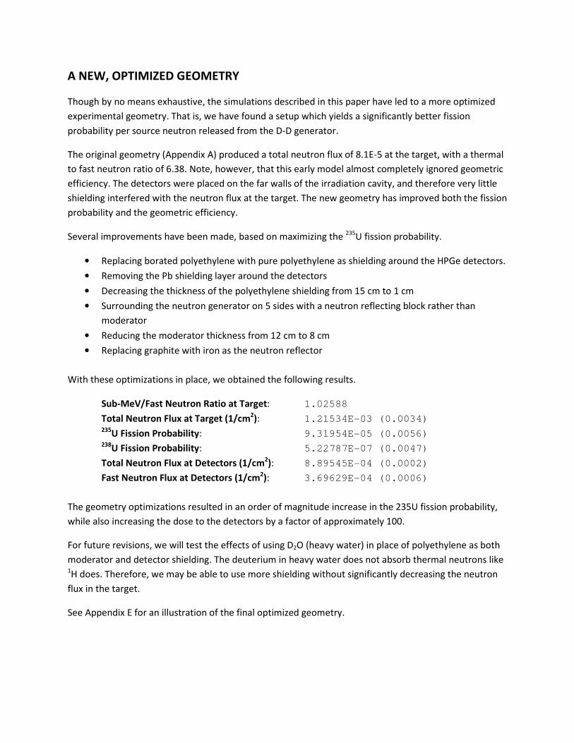
A NEW, OPTIMIZED GEOMETRY
Though by no means exhaustive, the simulations described in this paper have led to a more optimized
experimental geometry. That is, we have found a setup which yields a significantly better fission
probability per source neutron released from the D-D generator.
The original geometry (Appendix A) produced a total neutron flux of 8.1E-5 at the target, with a thermal
to fast neutron ratio of 6.38. Note, however, that this early model almost completely ignored geometric
efficiency. The detectors were placed on the far walls of the irradiation cavity, and therefore very little
shielding interfered with the neutron flux at the target. The new geometry has improved both the fission
probability and the geometric efficiency.
Several improvements have been made, based on maximizing the 235
U fission probability.
• Replacing borated polyethylene with pure polyethylene as shielding around the HPGe detectors.
• Removing the Pb shielding layer around the detectors
• Decreasing the thickness of the polyethylene shielding from 15 cm to 1 cm
• Surrounding the neutron generator on 5 sides with a neutron reflecting block rather than
moderator
• Reducing the moderator thickness from 12 cm to 8 cm
• Replacing graphite with iron as the neutron reflector
With these optimizations in place, we obtained the following results.
Sub-MeV/Fast Neutron Ratio at Target: 1.02588
Total Neutron Flux at Target (1/cm2): 1.21534E-03 (0.0034)
235U Fission Probability: 9.31954E-05 (0.0056)
238U Fission Probability: 5.22787E-07 (0.0047)
Total Neutron Flux at Detectors (1/cm2): 8.89545E-04 (0.0002)
Fast Neutron Flux at Detectors (1/cm2): 3.69629E-04 (0.0006)
The geometry optimizations resulted in an order of magnitude increase in the 235U fission probability,
while also increasing the dose to the detectors by a factor of approximately 100.
For future revisions, we will test the effects of using D2O (heavy water) in place of polyethylene as both
moderator and detector shielding. The deuterium in heavy water does not absorb thermal neutrons like 1H does. Therefore, we may be able to use more shielding without significantly decreasing the neutron
flux in the target.
See Appendix E for an illustration of the final optimized geometry.
RESULTS: FAST NEUTRONS AND DAMAGE TO THE DETECTORS
As I mentioned earlier, HPGe crystals can withstand a certain amount of fast neutron exposure before
radiation damage in the crystal lattice decreases performance. The threshold is approximately 1E9 total
fast neutrons / cm2. (Here, all neutrons with energy above 100keV are counted as “fast”.) Naturally,
since detectors are expensive, we don’t want to expose them to non-reversible damage in one or two
measurements! It is possible to repair crystals through thermal annealing, though this is time
consuming, and may not fully repair the lattice structure of the HPGe.
Reductions in the amount of polyethylene present in the experimental geometry have been shown to
increase fission probabilities. However, this goes hand-in-hand with increased radiation exposure to the
detectors.
Table 5 summarizes the fast neutron fluxes through the HPGe crystals for most of the simulations. Note
that all of the readings are averages over both detectors. Again, in this context, a fast neutron is any
with energy greater than 100keV.
Since several different parameters were varied throughout the simulations, I will use abbreviations to
describe geometries. The abbreviations are as follows:
• modXX
For tests optimizing the thickness of the moderator between the neutron generator and the
irradiation cavity. XX is the thickness (in cm) of the polyethylene.
All of these runs use the 15 cm Pb/polyethylene shield around the detectors, which are 22 cm
from the target.
• distXX
Corresponds to the simulations that dealt with the distances between the HPGe detector
crystals and the target. XX is the distance between a detector's front face and the target.
The moderator thickness is held constant at 12 cm, with the same shielding as the modXX runs.
• MatYY
Specifies the configuration options used in the runs dealing with shielding and reflector
materials. YY is a list of the options used.
The moderator thickness is held constant at 12 cm, and the detectors are placed 4 cm from the
target.
• shldXX
For runs varying the thickness of polyethylene shielding around the HPGe crystals. XX is the
thickness of the shielding layer on either side of a crystal.
The moderator thickness is held constant at 12 cm, and the detectors are placed 4 cm from the
target. In addition, all Pb shielding around the detectors was replaced by polyethylene.
No exposure tallies were made for the modXX simulations.

See the previous page for an explanation of the abbreviations for “Geometry Used”.
GEOMETRY
USED
TOTAL
NEUTRON
FLUX
FAST
NEUTRON
FLUX
GEOMETRY
USED
TOTAL
NEUTRON
FLUX
FAST
NEUTRON
FLUX
dist22 2.86039E-05
(0.0010)
4.64759E-06
(0.0055) shld14 5.69553E-06
(0.0023)
5.68571E-07
(0.0149)
dist12 2.72000E-05
(0.0011)
4.30735E-06
(0.0058) shld13 6.97506E-06
(0.0021)
7.13937E-07
(0.0133)
dist11 2.57272E-05
(0.0011)
4.07305E-06
(0.0059) shld12 8.54845E-06
(0.0018)
9.02760E-07
(0.0118)
dist10 2.40379E-05
(0.0011)
3.80358E-06
(0.0062) shld11 1.05230E-05
(0.0017)
1.14159E-06
(0.0105)
dist09 2.20472E-05
(0.0012)
3.50640E-06
(0.0064) shld10 1.29677E-05
(0.0016)
1.45530E-06
(0.0093)
dist08 1.97463E-05
(0.0012)
3.16666E-06
(0.0067) shld09 1.60255E-05
(0.0014)
1.85859E-06
(0.0082)
dist07 1.72299E-05
(0.0013)
2.78692E-06
(0.0072) shld08 1.98225E-05
(0.0013)
2.37595E-06
(0.0073)
dist06 1.45307E-05
(0.0014)
2.36218E-06
(0.0078) shld07 2.45786E-05
(0.0011)
3.05268E-06
(0.0064)
dist05 1.18944E-05
(0.0016)
1.94642E-06
(0.0086) shld06 3.04894E-05
(0.0010)
3.94834E-06
(0.0057)
dist04 9.64685E-06
(0.0018)
1.60553E-06
(0.0095) shld05 3.79055E-05
(0.0009)
5.10796E-06
(0.0050)
MatA 4.68605E-06
(0.0025)
4.54320E-07
(0.0166) shld04 4.71872E-05
(0.0008)
6.65440E-06
(0.0044)
MatB 1.52689E-05
(0.0013)
2.19425E-07
(0.0082) shld03 5.88793E-05
(0.0008)
8.72754E-06
(0.0039)
MatAB 6.08605E-06
(0.0021)
5.15390E-07
(0.0156) shld02 7.36066E-05
(0.0007)
1.15351E-05
(0.0034)
MatC 9.67549E-06
(0.0018)
1.62097E-06
(0.0095) shld01 9.22289E-05
(0.0006)
1.55328E-05
(0.0029)
MatD 9.18196E-06
(0.0018)
1.55872E-06
(0.0097) shld00 9.91258E-05
(0.0006)
2.24857E-05
(0.0025)
TABLE 5: DETECTOR NEUTRON EXPOSURES
Note that the HPGe crystals, with 4 cm radii and 8 cm lengths, have surface areas of 301.6 cm2.

SIGNAL STRENGTHS VERSUS NEUTRON EXPOSURE TO THE DETECTORS
From the sets of simulations discussed, we can make the following general observations.
• Decreasing the thickness of moderator between the generator and the target improves the thermal
neutron flux at the target, and hence increases the fission probability. This only applies down to a
certain size, but the moderator tests showed a steady improvement down to 8 cm thickness.
However, decreasing the amount of moderator also increases the fast neutron flux through the
detectors.
• The neutron generator should be surrounded on five sides by a neutron reflector, rather than
polyethylene. This increases the number of fissions in the HEU target by about a factor of 2. The
radiation exposure to the detectors is similarly increased.
• Using iron rather than graphite as neutron reflector yields a very slight performance improvement,
on the order of 5%.
• If we are to put the HPGe detectors closer to the target, then we must also vastly decrease the
thickness of the shielding surrounding them. The extra polyethylene absorbs much of the thermal
neutron flux that would otherwise cause fission in the target. Of course, doing so results in much
higher fast neutron fluxes in the detector crystals.
Disregarding the radiation damage to the detectors for now, consider the following. In our simulations
of delayed gamma responses, we determined the gamma yields per 1000 fissions, separated in 50ms
time bins over a 10s counting period. Generally, the minimum yields are on the order of 0.002 gammas
per 1000 fissions per 50ms.
If we want to achieve a maximum 1% uncertainty in any of the time bin, we need to measure 10,000
counts in that channel. Given our gamma yields, we would then need 5E9 fissions to obtain the desired
precision.
The maximum fission probability for this geometry is on the order of 3E-5 fissions per source neutron,
when combining all of the optimizations discussed so far.
Thus, we’ll need to generate 1.7E14 source neutrons to make the measurement on a 1.50777g HEU pin.
The fast neutron flux through either HPGe crystal is approximately 3E-4 neutrons per cm2 per source
neutron. Thus, 1.7E14 source particles results in a fast neutron exposure of 5E10 neutrons per cm2. (This
is 50 times greater than the “lethal” dose for the crystals.)
Also, assume we use a neutron generator of strength 1E8 neutrons per second, with a 10.12s duty cycle
and 100ms pulse length. Then we’d obtain 1E7 neutrons per pulse, and we would need to measure over
1E7 counting periods. Such a measurement would take roughly 2000 days.

OTHER FACTORS AND LIMITATIONS
We may be able to reduce the number of source neutrons needed to run a measurement. Consider the
time binning of the gamma yields. While we had calculated the gamma signals for 50ms time windows,
we will not need such fine resolution. The extra information gained by the time dependence serves to
define the shape of the gamma response, which depends on the nucleus that fissioned.
However, it does not take 200 points (10 seconds split into 50ms bins) to accurately define a gamma
response curve. In fact, we may be able to use as few as 10 time bins, thereby reducing the required
fission amount by a factor of 20.
Furthermore, all of the simulations use a single, 1.50777 g uranium oxide pellet to determine fission
probabilities. Increasing the fissionable mass of the target would result in a roughly linear increase in the
number of fissions, and hence emitted delayed gammas. We currently have 12 identical HEU pellets
(18.1 grams total), which lends another factor of 12 in reducing the number of source neutrons.
We may also be able to make a geometrical improvement in the shape of the target. Because the cross-
section for thermal fission in 235
U is very large (on the order of 1000 barns), fission events are more likely
to occur near the surface of an HEU pellet. (Given that the UO2 pellets have a mass density of 10.97
g/cm3, with 43% enrichment in
235U, the skin depth for thermal neutrons is roughly 0.09 cm.)
If we were the melt the 12 pellets into a foil of thickness equal to the skin depth, it would cover a cross-
sectional area of 18 cm2. The pellets themselves are 0.5 cm in diameter and 0.7 cm long, so each shows
a maximum cross-section of 0.35 cm2. Thus, 12 pellets have a combined cross-sectional area of 4.2 cm
2.
Exposing a larger surface to the interrogating neutrons would result in a higher fission probability per
source neutron.
However, there are other factors that decrease the sensitivity of our measurements. First, we have
neglected the detection efficiency of the HPGe detectors, instead assuming that all the emitted delayed
gamma rays are counted. For high gamma ray energies, the intrinsic efficiency of our crystals is on the
order of 10%. Furthermore, the geometric efficiency of our setup is close to 33%. So, perhaps as few as 1
in 30 emitted gammas are actually detected.
Consider, too, that this experiment aims to determine the amounts of multiple fissionable nuclides in a
mixed sample. While our current target contains only 235
U and 238
U, we want to apply the delayed
gamma technique to samples that may also contain 239
Pu. To do so, we would need to precisely
characterize the difference between 235
U and 239
Pu gamma responses. This requires a much higher level
of statistics, and therefore a much stronger neutron source.
In the end, our current geometry is unlikely to be useful for spent fuel measurements. However, given a
much stronger neutron source, combined with better neutron shielding, we might yet make the more
complex measurements on spent fuel. A reactor equipped with a sample shuttling system would fulfill
both requirements.
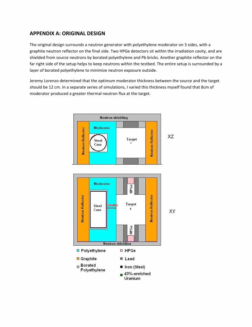
APPENDIX A: ORIGINAL DESIGN
The original design surrounds a neutron generator with polyethylene moderator on 3 sides, with a
graphite neutron reflector on the final side. Two HPGe detectors sit within the irradiation cavity, and are
shielded from source neutrons by borated polyethylene and Pb bricks. Another graphite reflector on the
far right side of the setup helps to keep neutrons within the testbed. The entire setup is surrounded by a
layer of borated polyethylene to minimize neutron exposure outside.
Jeremy Lorenzo determined that the optimum moderator thickness between the source and the target
should be 12 cm. In a separate series of simulations, I varied this thickness myself found that 8cm of
moderator produced a greater thermal neutron flux at the target.
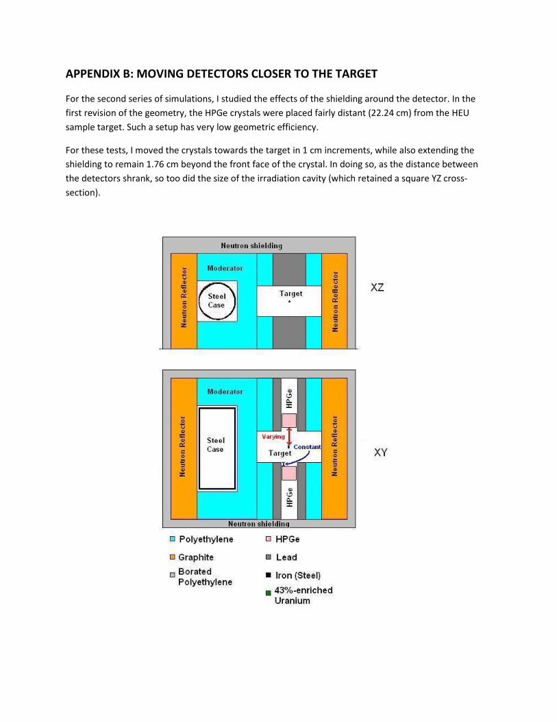
APPENDIX B: MOVING DETECTORS CLOSER TO THE TARGET
For the second series of simulations, I studied the effects of the shielding around the detector. In the
first revision of the geometry, the HPGe crystals were placed fairly distant (22.24 cm) from the HEU
sample target. Such a setup has very low geometric efficiency.
For these tests, I moved the crystals towards the target in 1 cm increments, while also extending the
shielding to remain 1.76 cm beyond the front face of the crystal. In doing so, as the distance between
the detectors shrank, so too did the size of the irradiation cavity (which retained a square YZ cross-
section).
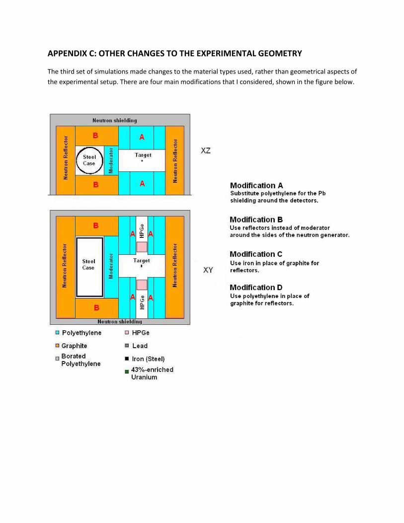
APPENDIX C: OTHER CHANGES TO THE EXPERIMENTAL GEOMETRY
The third set of simulations made changes to the material types used, rather than geometrical aspects of
the experimental setup. There are four main modifications that I considered, shown in the figure below.
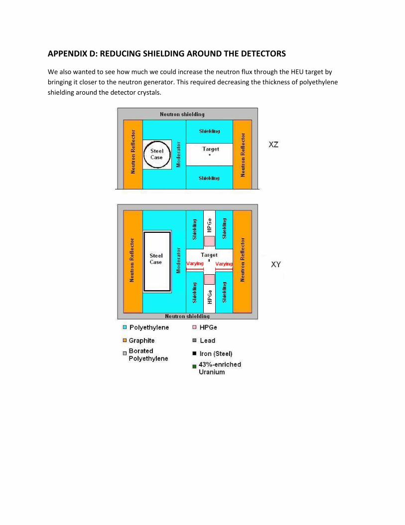
APPENDIX D: REDUCING SHIELDING AROUND THE DETECTORS
We also wanted to see how much we could increase the neutron flux through the HEU target by
bringing it closer to the neutron generator. This required decreasing the thickness of polyethylene
shielding around the detector crystals.
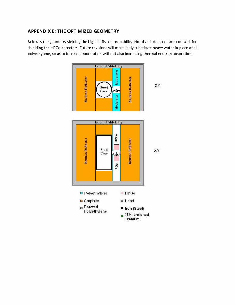
APPENDIX E: THE OPTIMIZED GEOMETRY
Below is the geometry yielding the highest fission probability. Not that it does not account well for
shielding the HPGe detectors. Future revisions will most likely substitute heavy water in place of all
polyethylene, so as to increase moderation without also increasing thermal neutron absorption.