Optimized Virtual Channel Assignment in the Cray XT Virtual Channel Assignment in the Cray XT Dennis...
27
Optimized Virtual Channel Assignment in the Cray XT Dennis Abts, Deborah Weisser, Jim Nowicki, and Robert Alverson {dabts, dweisser, nowicki, bob}@cray.com
Transcript of Optimized Virtual Channel Assignment in the Cray XT Virtual Channel Assignment in the Cray XT Dennis...

Optimized Virtual ChannelAssignment in the Cray XT
Dennis Abts, Deborah Weisser, Jim Nowicki,and Robert Alverson
{dabts, dweisser, nowicki, bob}@cray.com

5/7/07 Slide 2
Outline Overview of the Cray XT network
• Topology, Routing and Flow control Microarchitecture of the Cray SeaStar router
• Switch allocation and virtual channels Deadlock avoidance Optimizing virtual channel buffer assignment Results Conclusions

5/7/07 Slide 3
Interconnection Networks
On-chip
Router fabrics
I/O systems
Interconnection networks
Supercomputers

5/7/07 Slide 4
0.1
1
10
100
1000
10000
1985 1990 1995 2000 2005 2010
year
ba
nd
wid
th p
er
rou
ter
no
de
(G
b/s
)
Torus Routing ChipIntel iPSC/2J-Machine
CM-5Intel Paragon XPCray T3D
MIT AlewifeIBM VulcanCray T3E
SGI Origin 2000AlphaServer GS320IBM SP Switch2Quadrics QsNet
Cray X1Velio 3003IBM HPS
SGI Altix 3000Cray XT3YARC
Technology Trends for Router Bandwidth
ISCA-05: Kim, Towles, Gupta and Dally

5/7/07 Slide 5
Cray XT Network Overview
Architecturally scalesup to 32K nodes
3-Dtorus
7-ported router (Seastar)1 for the processorinjection/ejection and 6directions

5/7/07 Slide 6
Cray XT3 interconnect Network links are aggregated 4 links per cable
• Reduce cable bulk• Reduce cost

5/7/07 Slide 7
SeaStar Cables Bottom to top cooling
allows for a densecable mat
Each SeaStar cablecarries 38 GB/sec

5/7/07 Slide 8
Cray SeaStar (System-on-Chip) SOC
• 130nm ASIC• embedded 3-D torus router• 500 MHz• 3.2Gb/s signal rate• 12-bit wide ports• 460 Gb/s off-chip bandwidth

5/7/07 Slide 9
Seastar Interconnect: Balance
Issue is dedicated to high-performance interconnects
Features a paper fromBrightwell, Underwood &Pedretti on Cray’s SeaStarInterconnect
Good description on howSeaStar is designedspecifically for MPI
Table from paper
May-June issue of IEEE Micro

5/7/07 Slide 10
Seastar router block diagram 6-ported 3-D torus router with 12-bit network channels Fully buffered input and output ports Only 6 clocks of zero-load (fall-through) latency Routing is performed by a lookup table at each input port
• Can route a new packet every clock cycle

5/7/07 Slide 11
Packet Structure Packets consist of one or more flits Header flit contains routing fields
• Virtual channel, Destination, and Age Global and local routing tables
• 8 global table entries (selected by destination[14:12])• 4K local routing table entries
Target PortVC
Choice
0
4096
destination[11:0]
Local Routing Table

5/7/07 Slide 12
Virtual Channels Virtual channels (VCs) allow multiple buffers to be
multiplexed onto the same physical channel. Provide better throughput by avoiding head-of-line blocking Primarily used for avoiding deadlock on torus links
• Cray XT uses VC0 and VC1 One node in each dimension is labeled as the “dateline”
• Ensures that traffic “crossing” the dateline is on the appropriate VC• A packet that is going to cross the dateline to reach its destination
must start on VC0 and switch to VC1 when it crosses the dateline. This introduces imbalance near the dateline

5/7/07 Slide 13
VC Datelines

5/7/07 Slide 14
Balancing the load on virtual channels…

5/7/07 Slide 15
Improving VC buffer utilization Non-uniform virtual channel usage can result in a significant
variation in network performance depending on theprocessors position in the network [Adve and Vernon]
By balancing the relative traffic carried be each virtualchannel, we can have a significant effect on the overallnetwork performance.• Reducing the effects of head-of-line (HoL) blocking that leads to
congestion in the network

5/7/07 Slide 16
VC Assignment Policy Version 1 - dateline neighbors
• All traffic into the dateline enter on VC0 and exit on VC1• This causes acute VC imbalance around the dateline node and its
neighbors Version 2 - global routing table and dateline crossing
• The local routing tables can precisely route up to 4K nodes• Systems >4K nodes must first route to the correct “global” region
using the Global lookup table (GLUT)• Determining if the packet will cross a dateline in the X dimension
when moving toward the correct global region makes it a candidatefor balancing
Version 3• Dateline crossing within the region is always selected on the edge of
the region Guarantees that packets entering the region (within one direction)
will never cross the dateline• otherwise it would be destined to a different global region

5/7/07 Slide 17
Results - X dimension

5/7/07 Slide 18
Results Summary - X dimension

5/7/07 Slide 19
Results - Y dimension

5/7/07 Slide 20
Results Summary - Y dimension
5/7/07 Slide 21
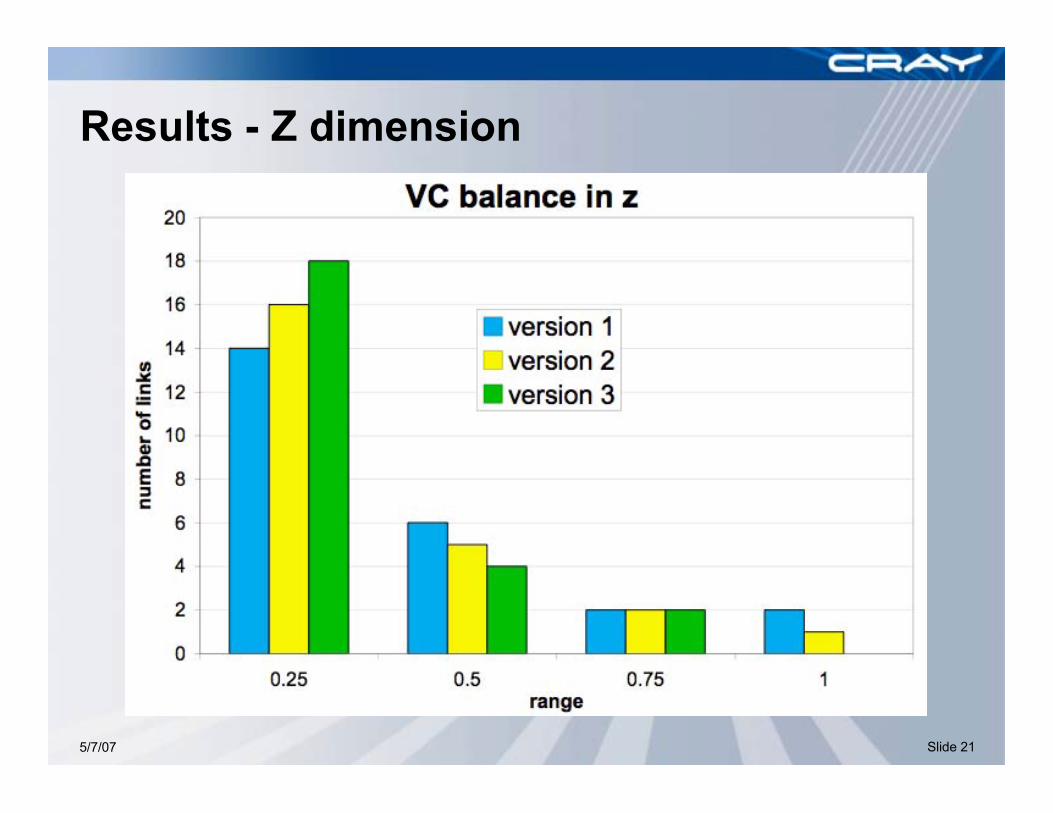
Results - Z dimension

5/7/07 Slide 22
Results Summary - Z dimension
5/7/07 Slide 23
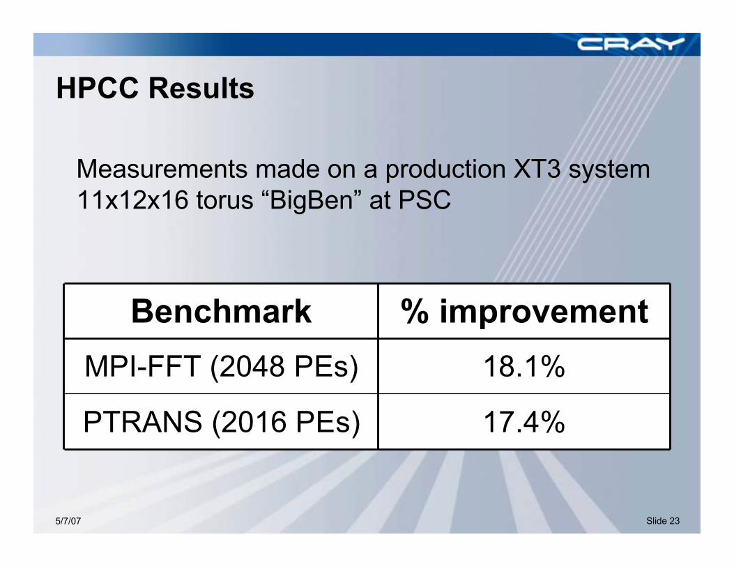
HPCC Results
17.4%PTRANS (2016 PEs)
18.1%MPI-FFT (2048 PEs)
% improvementBenchmark
Measurements made on a production XT3 system11x12x16 torus “BigBen” at PSC
5/7/07 Slide 24
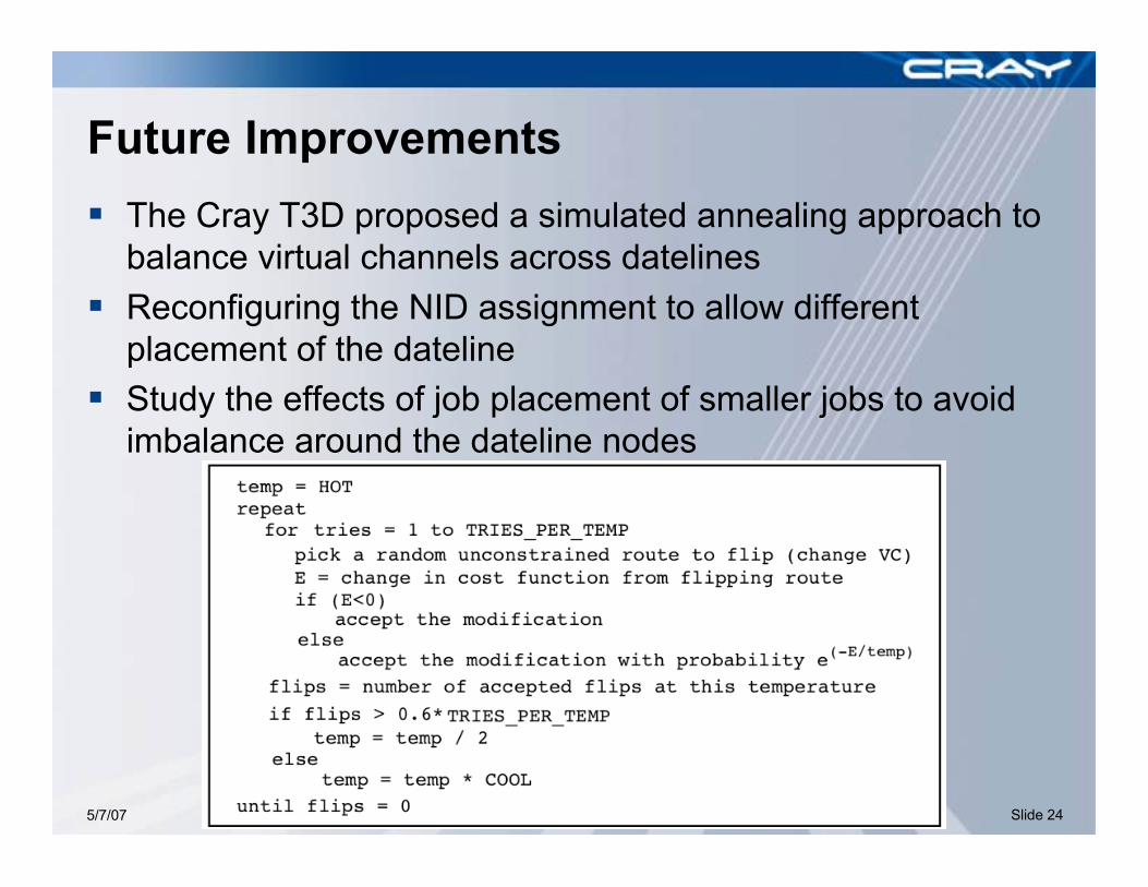
Future Improvements The Cray T3D proposed a simulated annealing approach to
balance virtual channels across datelines Reconfiguring the NID assignment to allow different
placement of the dateline Study the effects of job placement of smaller jobs to avoid
imbalance around the dateline nodes

5/7/07 Slide 25
Conclusions We use virtual channel “datelines” to avoid overlapping
dependencies around the torus links Buffer space in a high-performance router is a precious
commodity and must be balance to avoid unnecessary headof line (HoL) blocking
We show results of our optimized VC balance algorithm thatimproved performance• Show the optimization and its impact on buffer utilization
Improved VC balance by about 50%• X dimension: 44% down to 27%• Y dimension: 42% down to 28%• Z dimension: 42% down to 30%
The improved buffer utilization produced 18.1% increase forMPIFFT and 17.4% improvement in PTRANS results

5/7/07 Slide 26
Acknowledgements We would like to give special thanks to the team at
Pittsburgh Supercomputing Center (PSC) who collaboratedand gave feedback on early versions of the software
BigBen is an 11x12x16 XT3 system (now with Dual core!)

Thank You…
Questions?