Optimized needle shape reconstruction using experimentally ...
17
HAL Id: hal-02275011 https://hal.archives-ouvertes.fr/hal-02275011 Submitted on 11 Apr 2020 HAL is a multi-disciplinary open access archive for the deposit and dissemination of sci- entific research documents, whether they are pub- lished or not. The documents may come from teaching and research institutions in France or abroad, or from public or private research centers. L’archive ouverte pluridisciplinaire HAL, est destinée au dépôt et à la diffusion de documents scientifiques de niveau recherche, publiés ou non, émanant des établissements d’enseignement et de recherche français ou étrangers, des laboratoires publics ou privés. Optimized needle shape reconstruction using experimentally based strain sensors positioning Pierre-Loup Schaefer, Grégory Chagnon, Alexandre Moreau-Gaudry To cite this version: Pierre-Loup Schaefer, Grégory Chagnon, Alexandre Moreau-Gaudry. Optimized needle shape recon- struction using experimentally based strain sensors positioning. Medical and Biological Engineering and Computing, Springer Verlag, 2019, 57 (9), pp.1901-1916. 10.1007/s11517-019-02001-1. hal- 02275011
Transcript of Optimized needle shape reconstruction using experimentally ...

HAL Id: hal-02275011https://hal.archives-ouvertes.fr/hal-02275011
Submitted on 11 Apr 2020
HAL is a multi-disciplinary open accessarchive for the deposit and dissemination of sci-entific research documents, whether they are pub-lished or not. The documents may come fromteaching and research institutions in France orabroad, or from public or private research centers.
L’archive ouverte pluridisciplinaire HAL, estdestinée au dépôt et à la diffusion de documentsscientifiques de niveau recherche, publiés ou non,émanant des établissements d’enseignement et derecherche français ou étrangers, des laboratoirespublics ou privés.
Optimized needle shape reconstruction usingexperimentally based strain sensors positioning
Pierre-Loup Schaefer, Grégory Chagnon, Alexandre Moreau-Gaudry
To cite this version:Pierre-Loup Schaefer, Grégory Chagnon, Alexandre Moreau-Gaudry. Optimized needle shape recon-struction using experimentally based strain sensors positioning. Medical and Biological Engineeringand Computing, Springer Verlag, 2019, 57 (9), pp.1901-1916. 10.1007/s11517-019-02001-1. hal-02275011

Medical & Biological Engineering & Computing manuscript No.(will be inserted by the editor)
Optimized Needle Shape Reconstruction Using Experimentally-BasedStrain Sensors Positioning
Pierre-Loup Schaefer1 · Gregory Chagnon1 · Alexandre Moreau-Gaudry2
Received: date / Accepted: date
Abstract Needles are tools that are used daily during min-imally invasive procedures. During the insertions needlesmay be affected by deformations which may threaten thesuccess of the procedure. To tackle this problem, needleswith embedded strain sensors have been developed and asso-ciated with navigation systems. The localization of the nee-dle in the tissues is then obtained in real-time by reconstruc-tion from the strain measurements, allowing the physician tooptimize its gesture. As the number of strain sensors embed-ded is limited in number, their positions on the needle havea great impact on the accuracy of the shape reconstruction.The main contribution of this paper is a novel strain sensorpositioning method to improve the reconstruction accuracy.A notable feature of our method is the use of experimentalneedle insertion data, which increases the relevancy of theresulting sensor optimal locations. To the best of author’sknowledge no experimentally-based needle sensor position-ing method has been presented yet. Reconstruction valida-tions from clinical data show that the localization accuracyof the needle tip is improved by almost 40% with optimal lo-cations compared to equidistant locations when reconstruct-ing with two sensor triplets or more.
Keywords Instrumented needle · Needle reconstruction ·Sensor locations · Shape estimation · Strain sensor
Number of words of the abstract: 186 words
Pierre-Loup SchaeferE-mail: [email protected]
Gregory ChagnonE-mail: [email protected]
Alexandre Moreau-GaudryE-mail: [email protected] Univ. Grenoble Alpes, CNRS, Grenoble INP, TIMC-IMAG, 38000Grenoble, France2 Univ. Grenoble Alpes, CNRS, Grenoble INP, CHU Grenoble Alpes,TIMC-IMAG, 38000 Grenoble, France
Number of words of the manuscript: 4876 wordsNumber of figures: 7Number of tables: 5
1 Introduction
Needles are tools daily used during minimally invasive pro-cedures, such as in brachitherapy and biopsies [29]. Thesetherapeutic gestures require to guide the needle to a targetlocated in the patient body. To achieve this goal, physiciansneed to visualize the needle’s position in real-time in thetissue. Different navigation systems have been thus devel-oped to locate the needle in the tissue such as intraoperativesystems using ultrasound or computed tomography. Thesesystems have some drawbacks such as low precision or ir-radiations. To overcome these issues, some navigation sys-tems use preoperative images of the patient associated withspatial registration of the needle to localize the needle in thepatient tissue [41]. Most of these systems use the hypothesisthat the needle remains straight during the insertion. Unfor-tunately the needle may bend during the insertion becauseof its interaction with the tissues. Experimental insertionsin phantom models using 18 gauge 200 mm needles haveshown that tip deflection can be as high as 2.8 mm for a 6cm insertion [46] and 12 mm for a 10 cm insertion [32]. Inthis case, the hypothesis of a straight needle can have con-sequences such as attaining an undesired area of the tissues,leading to negative therapeutic results. Thus, in order to pro-vide the deformed shape of the needle to the physicians us-ing those systems, needle with embedded strain sensors havebeen developed. The goal is to increase the accuracy of thepositioning of the needle in the tissues in order to improvethe therapeutic results.
Instrumenting needle with strain sensors was first intro-duced by Park et al. [31] using Fiber Bragg gratings embed-

2 Pierre-Loup Schaefer1 et al.
ded on the needles to retrieve strain informations and usethem to reconstruct the deformed shape. Since then, needleinstrumented with strain sensors has been an intense topicof research with works by Henken et al. [16, 17], Abayazidet al. [1], Seifabadi et al. [42] or Roesthuis et al. [39, 40].One of the most crucial aspect of the works is the accuracyof reconstruction of the needle deformed shape. As the tech-nical limitations restricts the number of locations measureson the needle, the main problem consists in reconstructinga full deformed needle shape with only few strain measure-ments. Two aspects who play a crucial role in the recon-struction accuracy along the sensor sensibility are the needleshape reconstruction method and the locations of the sensorsmeasures on the needle. Different reconstruction methodshave been proposed for needles depending on the hypothe-sis made on the deformed needle shape during the insertion.The small displacement methods based on Euler-Bernoullibeam theory and presented in Park et al. [31], Abayazid etal. [1] and Seifabadi et al. will be used when the tip deflec-tion of the needle is small whereas the other reconstructionmethods proposed by Moon et al. [28], Roesthuis et al. [39]and Henken et al. [17] can be used otherwise. This problemof reconstruction, known as beam shape sensing, has alsobeen investigated by using 3D beam model such as Todd etal. [45] in the general case or by Xu et al. [50] in the field ofrobotic.
The problem of sensor positioning has been adressedby Kim et al. [20] and Mahoney et al. [26] for continuumrobots and by Park et al. [31] and Seifabadi et al. for nee-dles. In Kim et al. the curvature sensors are placed to min-imize the reconstruction error of the shape which is rep-resented as a linear combination of spatial functions. Thespatial functions are determined from actual robot config-urations. Mahoney et al. [26] generalized this method toother sensor types by using an information theoretic view-point and demonstrated that shape reconstruction and sensorplacement are coupled problems, involving that the sensoroptimal locations are dependant of the shape reconstructionmethod. Concerning the best sensor locations on a needle,Park et al. [31] and Seifabadi et al. [42] have both proposeda method which is based on the minimization of the recon-struction error of a reference set of deformed needles. Thisreference set of needles is constituted of 2D shapes of nee-dles built from a force model using Euler-Bernoulli beamtheory. The best sensor locations computed with this methodare thus restricted to small tip deflections and plane defor-mations only. Moreover, because they are built from forcemodels, the representativeness of the reference needles isnot guaranteed therefore compromising the relevancy of thesensor positions.
As in the works of Park et al. [31] and Seifabadi et al.[42], the sensor positioning method proposed in this paperis based on the minimization of the reconstruction error of
a reference needle set. But on the contrary of these two ex-isting methods, the reference needle set is not built from ar-bitrary deformed needles using a force model but is basedon actual configurations as suggested by Kim et al. [20] andMahoney et al. [26] and consists instead of real deformedneedles coming from medical images of experimental nee-dle insertions. The reference needles is thus composed of3D deformed needles shapes obtained by segmentation andsmoothing from CT scans of needle insertions which arethen used in combination with the beam model to obtainsimulated strain measures. Our sensor positioning methodis not then limited to 2D or small deflection deformations.It is believed that this approach increases the representative-ness of the reference needle set and therefore more valuablesensor location resulting in a higher gain of reconstructionaccuracy. The validation of these results from reconstruc-tion simulations with clinical images of needle insertionsshows that the mean accuracy is 40% better with the result-ing sensor locations than with equidistant locations whenreconstructing with two sensor triplets or more. To the bestof our knowledge, no experimentally-based needle sensorpositioning method has been presented yet.
Section 2 presents the medical images of needle inser-tions used in this article. Section 3 consider deflection hy-pothesis and their consequences on the accuracy of the nee-dle shape reconstruction. Section 4 introduces the needleshape reconstruction method and the strain sensor position-ing method. Results of optimal sensor location results arepresented and validated in Section 5. Finally, discussion andconclusion of our method are proposed in Section 6 and Sec-tion 7.
2 Material
This section presents the two sets of medical images of nee-dle insertions used in this study.
2.1 Experimental Needle Insertions
The first dataset is composed of 54 CT scans of experi-mental needle insertions into pig shoulder carried out byRobert et al. [37]. The needle insertions were performed ona fresh pig shoulder (approximate size: 300 mm × 200 mm× 100 mm) prepared in a plastic tray. The needles used forthe insertions were stainless steel 22 gauge 200 mm longneedles, standardly used in interventional radiology, withan estimated Young’s modulus of 200 GPa. The choice ofporcine tissue was driven by its extensive use in needle in-sertions experiments where it gives good performance as asubstitute for human tissue [18, 48, 19, 44]. As Ng et al.[30] point out, ”the best replica closest to human tissue is

Optimized Needle Shape Reconstruction Using Experimentally-Based Strain Sensors Positioning 3
Fig. 1 Histogram of the tip deflection of the needles com-ing from the experimental needle insertions.
the use of porcine tissue from specific portion of the ani-mals” ([30], p.187) and according to Brett et al. ”models de-veloped from porcine data will correlate with human speci-mens” ([7], p.341). Shoulder had been chosen for the pres-ence of tendons, muscles and bones. The use of a such com-plex environment of insertion is driven by the necessity toprovide the most complete range of needle deformations aspossible [37]. A CT scan acquisition of the whole tissue vol-ume was performed after each insertion. The insertions, asdescribed in Robert et al. [37], have been performed usingdifferent characteristics every time (rotation, efforts, etc...),purposely obtaining the widest range of deformations pos-sible to increase the representativity of the constituted set.The average tip deflection is 9 mm and the maximum tip de-flection is 23 mm. The histogram of the tip deflection of theneedles is presented in Fig. 1.
2.2 Clinical Needle Insertions
The second dataset is composed of 10 CT scans of a clin-ical trial performed at Grenoble-Alpes University Hospital,France. Different interventional radiology procedures wereperformed such as biopsies and injections. These CT scanswere selected on the basis of needle characteristics criteriasuch as length, gauge and material. All the clinical CT scansused in this works thus features insertions using 22 gauges200 mm stainless steel needles. On the opposite of the pre-vious CT scans set presented in Section 2.1, the characteris-tics of the insertions of the needles are unknown. This clini-cal trial received the authorization of the ANSM, the FrenchAgency for the Safety of Health Products, and the Comite deProtection des Personnes Sud Est V, the regional authorityfor human research protocols (ClinicalTrials.gov Identifier:NCT00828893). With an average of 5 mm and a maximum
Fig. 2 Histogram of the tip deflection of the needles com-ing from the clinical needle insertions.
of 11 mm the deflections of the needle tip are smaller thanin the case of the experimental needle insertions.
3 Small deflection vs large deflection hypothesis:consequences on the needle shape reconstructionaccuracy
The main contributions of this paper is a needle shape re-construction method covering 3D deformations and largedeflections and a strain sensor positioning method basedon experimental data. The needle deflection is the distanceat any of its point from its reference straight configurationwhen subjected to deformation. The deflections are usuallyconsidered large when the deflection is higher than 10% ofthe beam length and are considered small otherwise. Largedeflections are not always taken into account when recon-structing deformed needle shapes such as in Park et al. [31],Abayazid et al. [1] and Seifabadi et al. [42]. The impact ofthe small displacement hypothesis on the beam shape recon-struction will be evaluated here by considering the distancebetween the tips of needle shapes reconstructed with small-displacement and large-displacement hypothesis. For sim-plification purposes only cases of 2D bending deformationswill be considered. An initial straight beam of length L willbe considered with 2D coordinates being noted (x,y(x)). Inthe reference configuration the beam is undeformed and thusparallel to the x-axis: y(x) = 0. The expression of the curva-ture of the beam in the deformed configuration is noted κ
and is defined as follows:
y′′(x)
(1+ y′2(x))3/2 = κ(x) (1)
which gives by integration:
y′(x)√1+ y′2(x)
=∫ x
0κ(u)du (2)

4 Pierre-Loup Schaefer1 et al.
Table 1 Tip error of needle shape reconstructions with small displacement beam theory.
Needle characteristics Deformed needle shape tips comparisonL (mm) Y (L) (mm) Y (L)/L (%) ∆x(L) (mm) ∆y(L) (mm) d(L) (mm) d(L)/Y (L) (%)
100 12 12 % 0.87 0.03 0.87 8 %200 11 6 % 0.36 0.01 0.36 4 %200 23 12 % 1.59 0.04 1.61 7 %
The beam coordinates (x,y(x)) are parameterized by the ar-clength s and noted (x(s),y(x(s))). As only bending is con-sidered, the beam length is supposed to remain constant dur-ing the deformation and the abscissa x(s) of the beam at thearclength value s is then:
x(s) = x0 ∈ R / s =∫ x0
0
√1+ y′(x)2dx (3)
Using (2) and (3) we then have the following expression ofthe coordinate y(x(s)) of the beam [27]:
y(x(s)) =∫ x(s)
0
∫ v0 κ(u)du√
1− (∫ v
0 κ(u)du)2dv (4)
The coordinates of the beam given by the linear Euler-Bernoulli beam theory using the small displacement hypoth-esis will be noted (x, y(x)). Under the small displacementhypothesis the value of the term y′2 in (1) is neglected andthe expression of the curvature is then:
y′′(x) = κ(x) (5)
The beam coordinates (x, y(x)) are parameterized by the ar-clength s and noted (x(s), y(x(s))). Under the hypothesis ofsmall displacement the coordinate x(s) of the beam is:
x(s) = s (6)
Using (5) and (6) we then have the following expression ofthe coordinate y(x(s)) of the beam:
y(x(s)) =∫ s
0
∫ v
0κ(u)dudv (7)
Consequently, the linear Euler-Bernoulli beam model withsmall displacement include one approximation for each ofthe coordinates. Firstly, as shown in (6), the expression ofx(s) remains constant during the deformation and thus doesnot take into account the deformation of the beam. Secondly,as shown in (5) and then in (7) the curvature is approximatedwhich gives a simplified expression of the coordinate y(s).
The distance d at arclength s between the beam shapes(x(s),y(x(s))) and (x(s), y(x(s))) is:
d(s) =√
∆ 2x (s)+∆ 2
y (s) (8)
with:
∆x(s) = x(s)− x(s) (9)
∆y(s) = y(x(s))− y(x(s)) (10)
The expression of the distance d between the two recon-structed shapes depends obviously of the needle curvatureκ . In order to obtain a realistic evaluation of what the maxi-mum impact of the small displacement hypothesis can be onthe needle shape reconstruction, the distance d will be eval-uated with curvature functions obtained from real deformedneedles characteristics. Two large deflections and one smalldeflection needle deformations have thus been used to thisend: the 12 mm deflection of a 100 mm needle presentedin [32], the 23 mm deflection of a 200 mm needle comingfrom experimental needle insertions presented in Section 2.1and the 11 mm deflection of a 200 mm needle coming fromclinical neede insertions presented in Section 2.2. This char-acteristics of length and deflection are then used with 2Dlinear beam theory to obtain plausible curvatures of bend-ing beams satisfying those characteristics. The distance be-tween the two reconstructed end shapes d(L) constitute thetip error of reconstruction and is presented for each of thedeformations in Table 1. According to the results, the rel-ative tip errors d(L) appear to be mainly influenced by thecoefficient ∆x(L) and to be higher for large displacement de-formations (7% and 8%) than for small displacement defor-mations (4%). This means that the assumption made in (6)concerning the abscissa of the beam is the main factor of in-accuracy of Euler-Bernoulli beam theory for reconstructingneedles subjected to simple bending and that the higher thetip deflection is, the higher the relative tip error of recon-struction will be. As results show, taking into account largedisplacement thus helps to improve the reconstruction accu-racy in both cases of small and large deflections. The goal ofthis article being to improve the needle shape reconstructionaccuracy by positioning strain sensors optimally, using largedisplacement beam theory will first of all improve the accu-racy of the method of reconstruction of the needle shape.
The estimation of optimal sensor locations from ex-perimental needle data requires strain computations of de-formed needle shapes, hence the need to adopt a beam modelincluding the material configuration of the beam. One ofthe most convenient way to handle material configurationwas proposed by Cosserat [9] and consists in attaching aframe to each particle in the continuum. This parameteri-zation was used by Reissner [35] to develop a 1D contin-uum large displacement 3D beam theory extending previousworks of Kirchhoff [21] and Love [24]. The Cosserat 1Dcontinuum parameterization associated with the large dis-

Optimized Needle Shape Reconstruction Using Experimentally-Based Strain Sensors Positioning 5
placement modeling makes the Reissner beam theory per-fectly designed to handle needle structures undergoing largedeflections which might occur during needle insertions. Thesensor positioning method proposed in this paper uses theframe parametrization of the beam to formulate a differen-tial system expressing the deformation of the material frameof the needle in terms of strain configuration. This system isone of novelty of this work and the key element of both re-construction process and optimal sensor positioning. In fact,its resolution provides a comprehensive shape reconstruc-tion as an iterative method to obtain the shape of the needlefrom the strain measurements of the sensors. Conversely, as-sociated with curve framing the system is used in the sensorpositioning method to obtain the material frame of a needlefrom a given needle shape and simulate the measurementsof the strain sensors.
4 Methods
4.1 3D Needle Shape Reconstruction for Large Deflections
This section addresses the problem of reconstructing theshape of a needle using the data from its embedded strainsensors. First of all, the strain measures are acquired fromthe strain sensors and processed to retrieve the curvature andthe bending angle, two geometrical functions characterizingthe 3D deformation. The beam theory is then used to builda linear matrix differential system accounting of the needledeformation in terms of those two functions. This system issolved using a method of resolution for differential equationon a Lie algebra. Finally, an iterative scheme of reconstruc-tion for the needle shape is then presented.
4.1.1 Needle Curvature and Bending Angle
In most articles dealing with needles with embedded strainsensors located at the surface of the needle, the sensors areoriented parallel to the needle to measure the axial strain andplaced on needle cross sections by groups of three with a 120degrees angle between them [39, 1, 31, 16, 42], as shown inFig. 3. This orientation and distribution will be used in therest of this paper for each cross sections where sensors areplaced and will be called sensor triplets.
The deformation of a circular beam is presented in Fig.4. The beam radius is noted r0 and the cross section is de-fined by the intersection of the section plane Ps with thebeam. The sensor triplet located on the cross section is com-posed of strain sensors S1, S2 and S3 whose respective localstrain measures are ε1, ε2 and ε3. The intersection betweenthe section plane Ps and the beam neutral axis is denoted O.The curvature of the beam neutral axis at point O is denotedκ . The beam deformation is characterized by the plane ofbending Pb which contains C, the center of the osculating
Fig. 3 Sensor triplets composed of strain sensors S1, S2,S3 placed on a needle cross section with a 120 degrees anglebetween them.
circle to the beam neutral axis at point O. The points of crosssection with maximum and minimum strains are denoted re-spectively εmax and −εmax. The angle between the sensor S1and the point εmax is called the bending angle and is denotedθ . For linear elastic deformations, it is possible to expressthe local strain measures εi in terms of curvature κ , bendingangle θ and bias due to other deformations than bending δ
[39, 1, 16]:ε1 = r0κ cos(θ)+δ
ε2 = r0κ cos(θ − 2π
3 )+δ
ε3 = r0κ cos(θ − 4π
3 )+δ
(11)
By solving the set of equations (11) the parameters κ , θ
and δ are determined:
κ =1
3r0
√2((ε1− ε2)
2 +(ε2− ε3)2 +(ε1− ε3)
2)(12)
cos(θ) =2ε1− ε2− ε3√
2((ε1− ε2)
2 +(ε2− ε3)2 +(ε1− ε3)
2) (13)
sin(θ) =
√3(ε2− ε3)√
2((ε1− ε2)
2 +(ε2− ε3)2 +(ε1− ε3)
2) (14)
δ =ε1 + ε2 + ε3
3(15)
Considering a needle instrumented with n strain sen-sor triplets, the curvature and the bending angle values atthe location si of the ith triplet are noted respectively κiand θi. The estimate of curvature κest and the estimate ofbending angle θest can be obtained by interpolations of thesets (κi)i=1,..,n and (θi)i=1,..,n over [0,L] with the followingboundary counditions:
κest(L) = 0 (16)
θest(0) = 0 (17)

6 Pierre-Loup Schaefer1 et al.
Fig. 4 (a) Deformation of a beam element. The section plane is denoted Ps and contains the sensor triplets (S1,S2,S3).The plane of bending is denoted Pb and contains C the center of the osculating circle to the beam neutral axis at point O.(b) Diagram of the plane of bending Pb. The radius of curvature is denoted R. The points of cross section with maximumand minimum strains are denoted respectively εmax and −εmax.(c) Diagram of the section plane Ps. The angle θ is called the bending angle and is defined as the angle between S1 andεmax.
Condition from (16) reflects that curvature of the needle isnull at the distal extremity due to the absence of bendingmoment there whereas condition from (17) is used to givean initial value of bending angle. The method of interpo-lation used is linear interpolation with the following initialconditions:
κest(0) = κ1 (18)
θest(L) = θn (19)
4.1.2 Needle Deformation Model
The needle is modeled at its initial state by a cylindricalstraight beam of radius r0 and length L. The needle be-ing composed of isotropic material and its section beingsymmetric, the set of the centers of all the sections of thebeam composes the neutral axis. Needle deformations dueto shearing, tension and compression are neglected duringinsertions into tissue. The position of the beam neutral axisat length s is denoted r(s) in the reference configuration andR(s) in the current configuration. The convected coordinatesof the beam, which are embedded in the material and de-form along with the material [34], are defined in the refer-ence configuration by the orthonormal frame (t,n1,n2) witht tangent to the neutral axis r:
t = r′ (20)
and such that:
t = e1, n1 = e2, n2 = e3 (21)
with (e1,e2,e3) being the canonical basis of R3 as illustratedin Fig. 5a. The sensor triplets are placed on beam sectionssuch that vectors e2 are directed at sensors S1. The convectedcoordinates are defined in the current configuration by theorthonormal frame (T,N1,N2) as shown in Fig. 5b. As aconsequence of (20) we then have:
T = R′ (22)
The differentiation of (T,N1,N2) gives the following lineardifferential system [35]: T
N1N2
′
= Ω
TN1N2
(23)
with
Ω =
0 κ1 κ2−κ1 0 κt−κ2 −κt 0
(24)
The components of Ω are the torsion factor κt and the bend-ing factors κ1 and κ2. During the insertion the mechanicaltorsion of the needle can be ignored because of the geometryof the needle, its mechanical properties and its interactionswith the tissues, thus [1, 31]:
κt = 0 (25)
The components of Ω can be expressed in terms of curva-ture κ and bending angle θ using the Serret-Frenet frame(T,N,B) of the curve R. The vector T is the tangent vec-tor and is shared by the Frenet-Serret frame and the con-vected coordinates. The vector N is the normal vector and is
Optimized Needle Shape Reconstruction Using Experimentally-Based Strain Sensors Positioning 7
(a)
(b)
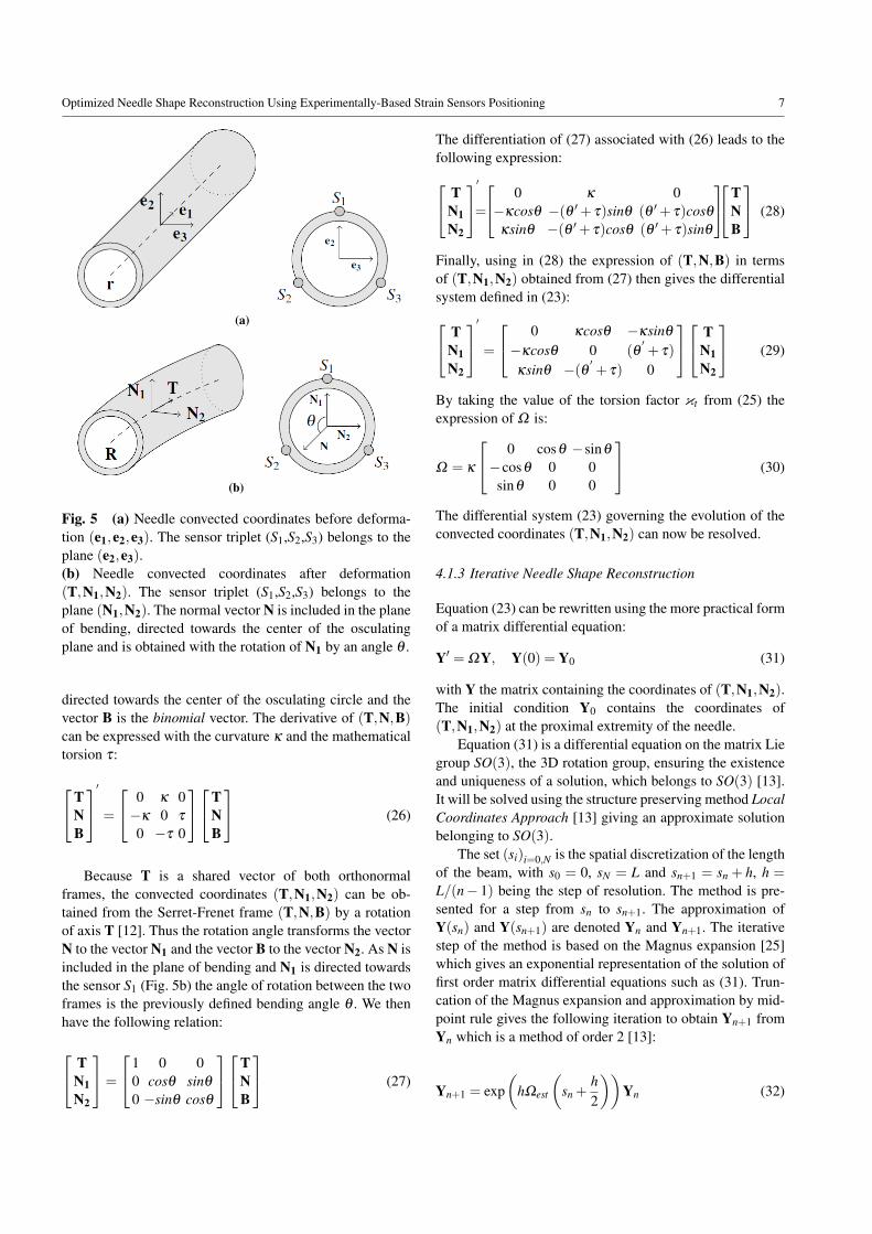
Fig. 5 (a) Needle convected coordinates before deforma-tion (e1,e2,e3). The sensor triplet (S1,S2,S3) belongs to theplane (e2,e3).(b) Needle convected coordinates after deformation(T,N1,N2). The sensor triplet (S1,S2,S3) belongs to theplane (N1,N2). The normal vector N is included in the planeof bending, directed towards the center of the osculatingplane and is obtained with the rotation of N1 by an angle θ .
directed towards the center of the osculating circle and thevector B is the binomial vector. The derivative of (T,N,B)can be expressed with the curvature κ and the mathematicaltorsion τ:
TNB
′
=
0 κ 0−κ 0 τ
0 −τ 0
TNB
(26)
Because T is a shared vector of both orthonormalframes, the convected coordinates (T,N1,N2) can be ob-tained from the Serret-Frenet frame (T,N,B) by a rotationof axis T [12]. Thus the rotation angle transforms the vectorN to the vector N1 and the vector B to the vector N2. As N isincluded in the plane of bending and N1 is directed towardsthe sensor S1 (Fig. 5b) the angle of rotation between the twoframes is the previously defined bending angle θ . We thenhave the following relation:
TN1N2
=
1 0 00 cosθ sinθ
0 −sinθ cosθ
TNB
(27)
The differentiation of (27) associated with (26) leads to thefollowing expression: T
N1N2
′
=
0 κ 0−κcosθ −(θ ′+ τ)sinθ (θ ′+ τ)cosθ
κsinθ −(θ ′+ τ)cosθ (θ ′+ τ)sinθ
TNB
(28)
Finally, using in (28) the expression of (T,N,B) in termsof (T,N1,N2) obtained from (27) then gives the differentialsystem defined in (23): T
N1N2
′
=
0 κcosθ −κsinθ
−κcosθ 0 (θ′+ τ)
κsinθ −(θ ′ + τ) 0
TN1N2
(29)
By taking the value of the torsion factor κt from (25) theexpression of Ω is:
Ω = κ
0 cosθ −sinθ
−cosθ 0 0sinθ 0 0
(30)
The differential system (23) governing the evolution of theconvected coordinates (T,N1,N2) can now be resolved.
4.1.3 Iterative Needle Shape Reconstruction
Equation (23) can be rewritten using the more practical formof a matrix differential equation:
Y′ = ΩY, Y(0) = Y0 (31)
with Y the matrix containing the coordinates of (T,N1,N2).The initial condition Y0 contains the coordinates of(T,N1,N2) at the proximal extremity of the needle.
Equation (31) is a differential equation on the matrix Liegroup SO(3), the 3D rotation group, ensuring the existenceand uniqueness of a solution, which belongs to SO(3) [13].It will be solved using the structure preserving method LocalCoordinates Approach [13] giving an approximate solutionbelonging to SO(3).
The set (si)i=0,N is the spatial discretization of the lengthof the beam, with s0 = 0, sN = L and sn+1 = sn + h, h =
L/(n− 1) being the step of resolution. The method is pre-sented for a step from sn to sn+1. The approximation ofY(sn) and Y(sn+1) are denoted Yn and Yn+1. The iterativestep of the method is based on the Magnus expansion [25]which gives an exponential representation of the solution offirst order matrix differential equations such as (31). Trun-cation of the Magnus expansion and approximation by mid-point rule gives the following iteration to obtain Yn+1 fromYn which is a method of order 2 [13]:
Yn+1 = exp(
hΩest
(sn +
h2
))Yn (32)

8 Pierre-Loup Schaefer1 et al.
with Ωest the estimate of Ω from (30) using the estimatesκest and θest as functions κ and θ . Equation (32) contains amatrix exponential. Using the formula for exponential map-ping in SO(3) gives the following expression [43]:
exp(
hΩest
(sn +
h2
))=
c1 s1c2 −s1s2−s1c2 c1 +αs2
2 αc2s2s1s2 αc2s2 c1 +αc2
2
(33)
with:
c1 = cos(
hκest
(sn +
h2
))(34)
s1 = sin(
hκest
(sn +
h2
))(35)
c2 = cos(
θest
(sn +
h2
))(36)
s2 = sin(
θest
(sn +
h2
))(37)
α = 1−hκest
(sn +
h2
)(38)
Using relation (32) iteratively on the set (si)i=1,..,n gives(Yi)i=1,..,n containing the coordinates of Ti the approxima-tion of T(si). We then have the set of the tangent approxi-mations (Ti)i=1,..,n. By using (22) we define Ri, the approx-imation of R(si), using the recurrence relation:
R0 = R(s0) (39)
Ri+1 = Ri +hTi
Finally the set (Ri)i=1,..,n is the three-dimensional recon-struction of the shape of the deformed needle.
4.2 Needle Sensor Positioning
The problem of sensor positioning involves finding the sen-sor triplet locations on a needle which provide the bestreconstruction accuracy. Such locations are called optimalsensor locations [42]. The reconstruction accuracy of a nee-dle is evaluated by an error measure between its originaland reconstructed shape. Thus, the optimal sensor locationsare the locations that minimize in average this error measure[20]. In practice, Park et al.[31] and Seifabadi et al.[42] es-tablished the optimal sensor locations as the locations thatminimize the mean of the error measure for some referenceneedles. Therefore, for given sensor locations, the recon-structed shape associated to a reference needle is obtainedby needle shape reconstruction with the strain inputs beingthe strains of the reference needle at the sensor locations. Intheir works, Park et al. [31] and Seifabadi et al. [42] builtthe reference needles using Euler-Bernoulli beam theory toreconstruct needle shapes from a 2D force model. Thus, the
deformations of their reference needles are restricted to 2Dsmall deflections.
The sensor positioning method proposed in this paper isbased on a novel approach using experimental needle inser-tions data to build the reference needle set. Figure 1 showsthat the deflection of some needle of the experimental datacan’t be qualified as large but still have high values, com-prised between 5% and 10% of the needle length. Accordingto Section 1, the processing of such needles thus justifies theuse of large displacement beam theory as the approximationusing a small displacement beam theory would degrade thequality of treatment, especially on the abscissa parameter-ization. By using the deformation model presented in Sec-tion 4.1.2 it is then possible to take complex deformationsinto account, such as 3D deformations or large deflections.The first part of this section presents a method to retrievethe deformed configuration of the needle from a scanner im-age. Thus, the convected coordinates of needles inserted intotissue are retrieved from the CT scans of the experimentalneedle insertions into pig shoulder presented in Section 2.1(Fig. 6a) and then used as reference needles. Finally, in thesecond part of this section, the needle sensor positioning isdefined as a minimization problem and its resolution is ad-dressed.
4.2.1 Reconstruction of Needle Deformed Configuration
This section describes the method to recover the 3D con-vected coordinates of a needle from a scanner image. Thismethod use the hypothesis and the deformation model pre-sented in Section 4.1.2.
Needle Voxel Segmentation The CT scan is segmented in or-der to separate needle voxels from surrounding tissues. Theseeded region growing technique is particularly appropriatebecause of the difference in voxel density between the tis-sues and the needle [2]. This algorithm was implementedas a plug-in in the medical visualization software CamiTK[11]. The results of the segmentation is a set containing allthe needle voxels, as shown in Fig. 6b.
Needle Shape Smoothing The needle voxels are the result ofa noisy spatial discretization of the needle shape. Therefore,it is possible to approximate the needle shape by smoothingthe needle voxels. The smoothing method used in this pa-per is the B-spline smoothing, one of the most commonlyused method to smooth data, which consists in performing aregularized regression on a B-spline basis.
B-splines are piecewise polynomials defined by their de-grees, knots and control points [6]. The degree of the splineis denoted n, the number of knots is denoted nk and thenumber of control points is denoted nc. The knots are de-noted (ti)i=1,..,nk ∈ Rnk and the control points are denoted

Optimized Needle Shape Reconstruction Using Experimentally-Based Strain Sensors Positioning 9
(a) (b)
(c) (d)
Fig. 6 Presentation of the different stages of the reconstruction process of a deformed needle. (a) The needle selected forillustration purpose has a planar deformation so that its insertion is fully visible in one slice of the CT scan. (b) The needlevoxels are extracted from the CT scans by segmentation (Section 4.2.1). (c) The shape of the needle as a 3D B-spline isobtained by spline smoothing (Section 4.2.1). (d) The convected coordinates of the needle are computed from its shape(Section 4.2.1)
(Pi)i=1,..,nc with ∀i,Pi ∈ R3. Let S be the B-spline which isdefined by:
S(t) =nc
∑i=1
Bi,n(t)Pi (40)
with the following recursive definition of the B-spline basisset (Bi,n)i=1,..,nc :
Bi,0(t) =
1 if ti ≤ t ≤ ti+1
0 otherwise(41)
Bi,n(t) =t− ti
ti+n− tiBi,n−1(t)+
ti+n+1− tti+n+1− ti+1
Bi+1,n−1(t) (42)
The definition of the B-spline basis ensures that the B-splineS is of class Cn−1. This property justifies the use of B-splineshere as it ensures that the resulting approximation of the nee-dle shape will be smooth.
Let (Xi)i=1,..,ndbe the set of the nd data points to smooth,
here the needle voxels, with Xk ∈ R3 containing the 3D co-ordinates of the kth voxel. Voxels have been pre-ordered us-ing the PCA-based method proposed by Furferi et al [38].The data points are associated to the B-spline points throughthe parameters (ti)i=1,..,nd which reflect the distribution ofthe data points along the B-spline. These parameters wereobtained using the centripetal parameterization method pro-posed by Lee [23] which is one of the most common methodused in solving the parameterization problem [14]. The
weight wk represents the contribution assigned to the datapoint Xk during the smoothing. The voxel values were usedas weights because they decrease with distance between thevoxel and the needle neutral axis, therefore giving less sig-nificancy to voxels located far from the needle neutral axis.The smoothing system takes the following form:nd
∑l=1
wl ‖S(tl)−Xl‖2 +λ
∫ 1
0
∥∥∥S(m)(t)∥∥∥2
dt (43)
with m the degree of smoothing and S a B-spline of degree2m− 1 [10]. The value of the smoothing degree for (43) isset to m = 3 which corresponds to quintic B-splines and al-lows correct estimates of first and second derivatives of thedata to be obtained [49]. The quality of these estimates iscrucial as they are further used to compute curvature andbending angle functions. The smoothing B-spline estimateis defined to be the minimization of (43) over the controlpoints (Pi)i=1,..,nc . The first term of (43) reflects the accu-racy of the data points whereas the second term expressesthe roughness of the estimate. The trade-off between thesetwo terms is the variable λ , called the smoothing parameter.
The choice of the smoothing parameter λ is critical asit impacts the accuracy and the roughness of the solution.The optimal value of λ can be defined as the value whichminimizes the shape error between the deformed needle andthe reconstruction from its voxels discretization. This valueis shape dependant and then each deformed needle has its

10 Pierre-Loup Schaefer1 et al.
own optimal value of λ . In our case, the deformed nee-dle data is unavailable as we only have the discrete voxelsfrom segmented scans. Nevertheless, it is possible to over-come this situation by using methods such as GeneralizedCross-Validation [10] which gives us the optimal value ofthe smoothing parameter for a given deformed needle fromits voxel discretization. Finally the shape of the needle in theCT scan is reconstructed, as shown in Fig. 6c.
Computation of the Needle Convected Coordinates Thesimplest way to obtain the convected coordinates of the nee-dle consists of rotating the Serret-Frenet frame as shownin (27). Nevertheless, as the computation of the Serret-Frenet frame can result in an undesirable rotation aroundthe tangent of the curve, especially when the curve is almoststraight, more stable computations of other frames are of-ten preferred to the Serret-Frenet frame [47]. The methodemployed here is the Double reflection method, proposed byWang et al., which computes the rotation-minimizing frames(RMF) of a curve with a fourth order of approximation error.The RMF is a 3D orthonormal frame based on Bishop ap-plication of parallel transport to curve framing composed ofa vector tangent to the curve and two vectors whose deriva-tives are tangential [3]. Equation (29) and (30) shows thatwhen the torsion of the needle is ignored the derivativesN1′=−κ cosθT and N2
′= κ sinθT are tangential and then
the convected material frame of the needle (T,N1,N2) isa RMF which can be computed with the double reflectionmethod, as shown in Fig. 6d.
4.2.2 Optimization Problem
The set containing the convected coordinates of the refer-ence needles is denoted N , it was obtained from the pigneedle insertion experimental data presented in Section 2.1which was processed as described in Section 4.2.1. The con-vected coordinates of a needle can then be used to recon-struct the needle shape and to simulate strain sensor mea-sures. The error measure used is the tip error employed byPark et al. [31] and Seifabadi et al. [42], which is the dis-tance between the tip of the reference needle and the tip ofits reconstructed shape. This choice is driven by the fact thata correctly positioned needle tip is one of the principal fac-tors for success in interventional radiology procedures. Thefunction giving the tip position of a needle is denoted tip.The optimal sensor locations are the locations that minimizethe sum of squared error measure between the reference nee-dle N and its reconstructed shape rec(N,L) from given sen-sor locations L . Let L be the set of locations of nt sensortriplets on a needle of length L. The problem of the opti-mal sensor triplet locations is then defined as the following
optimization problem:
minimizeL∈L ∑
N∈N‖tip(N)− tip(rec(N,L))‖2 (44)
This optimization problem belongs to the Mixed Inte-ger Nonlinear Programming (MINLP) family as it is a prob-lem with a nonlinear objective function and the solutionsconsidered are integers. Thus MINLP optimization algo-rithms have been used to solve (44). The algorithms selectedare NOMAD[22], KNITRO[8] and MATLAB genetic algo-rithm. Finally, the locations minimizing (44) are the optimalsensor triplet locations.
5 Results
The works concerning instrumented needles differ by thenumber of triplets per needle. This number is the numberof cross section instrumented with strain sensors, mostlybased on fiber Bragg gratings technology. The instrumenta-tion presented in the litterature use two [31], three [15, 42],four [1, 39] or five [17] triplets. Consequently, in order tocover all possible cases, the number of triplet considered iscomprised between one (the minimum number of triplet re-quired to instrument a needle) and five (the maximum num-ber of triplet of an instrumented needle presented in the lit-terature). The minimization described in Section 4.2.2 wasthen performed on the set of the experimental needle inser-tions for a number of sensor triplets from one to five. Theresulting optimal locations of sensor triplets are presentedin Table 2. Locations are specified in mm from the proximalextremity of the needle.
Table 2 Optimal sensor triplet locations. Locations are ex-pressed as distances in mm from the proximal extremity ofthe needle.
Number ofsensors triplets
Optimal sensor triplet locations (mm)l1 l2 l3 l4 l5
1 812 28 1013 25 77 1364 9 40 95 1445 11 34 77 128 171
For comparison purposes, optimal locations were usedalong with equidistant locations to reconstruct the experi-mental and clinical needle sets. Boxplots of tip errors of thereconstructed needles are presented in Fig. 7. These resultsshow that, for both needle sets, the quartiles and the maxi-mal tip error are smaller with sensors placed at optimal loca-tions than with sensors placed at equidistant locations. Themean tip error for both sets, presented in Table 3, is also

Optimized Needle Shape Reconstruction Using Experimentally-Based Strain Sensors Positioning 11
Table 3 Reconstruction results of the needle from experimental and clinical insertions with sensors triplets placed atequidistant and optimal locations. P-values were calculated using a Wilcoxon signed-rank test on tip errors.
Needle set Number ofsensors triplets
Reconstruction tip error Gain in accuracyEquidistant locations Optimal locations
Mean (mm) Median (mm) Mean (mm) Median (mm) Mean±SD (mm) Relative mean (%) P-value
Experimental
1 9.67 8.43 8.03 8.08 1.64 ± 5.58 17% 0.0532 5.57 5.12 3.93 3.69 1.64 ± 3.29 29% 0.0023 4.32 3.45 3.25 2.67 1.07 ± 3.04 25% 0.0174 3.60 3.08 2.65 2.04 0.95 ± 2.51 26% 0.0105 3.38 2.65 2.21 1.89 1.17 ± 1.87 35% < 0.001
Clinical
1 8.08 7.13 8.04 6.45 0.04 ± 2.21 < 1% 1.0002 4.25 3.86 2.33 2.40 1.92 ± 2.56 45% 0.0633 2.86 2.75 1.41 1.18 1.45 ± 1.28 51% 0.0634 1.71 1.00 0.91 0.64 0.80 ± 0.76 47% 0.0315 1.62 0.95 0.91 0.58 0.70 ± 1.04 43% 0.031
smaller with optimal locations. Therefore, the gain of ac-curacy which is defined by the difference between the tiperror with equidistant locations and tip error with optimallocations is positive in every case. The gain of accuracy iscomprised between 0.95 mm and 1.64 mm for experimen-tal needle insertions and between 0.04 mm and 1.92 mm forclinical needle insertions. To determine the statistical sig-nificance of these gains, a Wilcoxon signed-rank test wasperformed on the tip errors to test whether the mean tip er-ror differs. The significance threshold was set at 0.05. Theresulting p-values, presented in Table 3, show that there issignificant differences between the tip errors of reconstruc-tions of the experimental needle insertions with a numberof triplets greater than 2 and between the tip errors of re-constructions of the clinical needle insertions with a numberof triplets greater than 4. Finally, when the gain in accu-racy is statistically significant, the use of optimal locationsimproves in average the reconstruction accuracy by 25% to35% for experimental needle insertions, as presented in Ta-ble 3, and by 43% to 47% for clinical needle insertions, asshown in Table 3.
Needles have also been reconstructed using optimal sen-sors triplets locations coming from the works of Park et al.[31] and Seifabadi et al. [42]. The locations provided in Parket al. [31] for two sensor triplets on a 150 mm needle corre-sponds to 15% and 57% of the needle length and locationsprovided in Seifabadi et al. [42] for three sensor triplets ona 110 mm needle corresponds to 13%, 39% and 68% of theneedle length. Reconstruction results of both needle inser-tions sets using those values as sensors triplets locations arepresented in Table 4 and Table 5. Results show there is a sta-tistically significant gain in accuracy using the optimal loca-tions instead of the locations obtained from Park et al. [31]for the reconstruction of the experimental needle set and thatthe gain is also statistically significant when the optimal lo-cations are used instead of locations obtained from Seifabadi
et al. [42] for the reconstruction of both experimental andclinical needle sets. The use of optimal locations thus im-proves the reconstruction accuracy by 11% compared to lo-cations from Park et al. [31] and between 62% and 69%compared to locations from Seifabadi et al. [42].
6 Discussion
The locations of the strain sensors on the needle are criticalbecause of their impact on the needle shape reconstruction.Therefore, as the number of embedded sensors on needlesis limited due to technical restrictions, positioning sensorsappropriately constitutes an efficient way to improve recon-struction accuracy. A new method to compute the optimallocations of the strain sensor triplets of a needle has beenproposed in this study. The results demonstrate that the re-construction is more accurate with these locations comparedto equidistant locations and locations presented in the liter-ature.
The optimal locations computed using experimentalneedle insertions data and presented in Table 2 demonstratethat optimal locations are much closer to the proximal ex-tremity than the distal extremity of the needle. In fact, thecloser from the proximal extremity a reconstruction impreci-sion is made, the worst the reconstruction is. Hence the needto acquire more deformation informations near the proximalextremity, which explains a larger sensor density near thatarea. The results of reconstruction with equidistant and opti-mal locations show that in every case the tip error is smallerwhen the sensor triplets are located at optimal locations. Fora number of triplets greater than two, the gain in accuracystays similar in each set (29%, 25%, 26%, 35% for exper-imental needle set and 45%, 51%, 47%, 53% for clinicalneedle set) and do not have specific trends. On the opposite,when the number of triplets increases the standard deviationdecreases, meaning that the dispersion of the gain in accu-

12 Pierre-Loup Schaefer1 et al.
Table 4 Reconstruction results of the needle from experimental and clinical insertions with sensors triplets placed at loca-tions obtained from Park et al. [31] and optimal locations. P-values were calculated using a Wilcoxon signed-rank test on tiperrors.
Needle set Number ofsensors triplets
Reconstruction tip error Gain in accuracyLocations from Park et al. Optimal locations
Mean (mm) Median (mm) Mean (mm) Median (mm) Mean±SD (mm) Relative mean (%) P-valueExperimental 2 4.43 4.30 3.93 3.69 0.51±1.86 11% 0.045
Clinical 2 2.58 2.55 2.33 2.40 0.25±0.99 10% 0.188
Table 5 Reconstruction results of the needle from experimental and clinical insertions with sensors triplets placed at loca-tions obtained from Seifabadi et al. [42]. P-values were calculated using a Wilcoxon signed-rank test on tip errors.
Needle set Number ofsensors triplets
Reconstruction tip error Gain in accuracyLocations from Seifabadi et al. Optimal locationsMean (mm) Median (mm) Mean (mm) Median (mm) Mean±SD (mm) Relative mean (%) P-value
Experimental 3 8.66 7.38 3.25 2.67 5.41±4.93 62% < 0.001Clinical 3 4.52 4.42 1.41 1.18 3.11±3.37 69% 0.031
racy decreases as well. In this case, it signifies there is moreand more cases where the reconstruction is better with theoptimal locations than with the equidistant locations. Oneexplanation is that with the increase of the sensor density onthe needle the deformations are less likely to be unnoticed.It thus minimizes the randomness of the deformations onthe reconstruction accuracy. Consequently, as the p-valuesdecreases, the gain in accuracy obtained with the use of theoptimal locations are more and more statistically significant.For the experimental needle insertions the gain in accuracybecomes statistically significant when the number of tripletsconsidered is greater than 2 and for the clinical needle inser-tions when the number of triplets is greater than 4.
To the best of the author’s knowledge there is no work inthe literature concerning optimal locations of sensor tripletsfor a 200 mm long needle. Park et al. [31] presented optimallocations for a 150 mm long needle and Seifabadi et al. [42]for a 110 mm long needle. The locations were computedfrom uniformly distributed load and concentrated forces atthe extremity. The chosen load values are reflecting the inter-action with the tissue during the insertion and are thus inde-pendant from the needle length. Optimal locations from Parket al. [31] and Seifabadi et al. [42] have then been scaled tofit on 200 mm needles, giving optimal locations of 29 mmand 113 mm for Park et al. [31] and 55 mm, 144 mm and180 mm for Seifabadi et al. [42]. The optimal locations fortwo triplets presented in Table 3 are very close to those ob-tained from Park et al. [31] whereas the optimal locationsfor three triplets are very distant from the one obtained fromSeifabadi et al. [42]. One of the reason is that, in the work ofSeifabadi, the number of sensors activated varies during theinsertion. Nevertheless, when the needle is fully inserted allsensors are activated, as in our case, which makes the use ofthese locations relevant. In every case the tip error of the re-
construction are smaller with the optimal locations than withlocations obtained from the literature. The gain in accuracyusing the optimal locations is 10% and 11% compared toPark et al. [31] and 62% and 69% compared to Seifabadi etal. [42].
These gains in accuracy are statistically significant ex-cept for the reconstruction of the clinical needle set withtwo triplets. This result is due to the limited number of el-ements of the clinical needle set. This phenomenon, asso-ciated with the effect discussed above about reconstructionwith a limited number of triplet, is also the cause of the al-most null gain in accuracy (0.04 %) when reconstructingwith one triplet the clinical needle set using optimal loca-tions compared to equidistant locations. Thus, the reducedsize of the clinical needle set constitutes a limitation of theresults presented here and could be corrected by consider-ing a larger set of needle insertions. Another limitation ofour method is the quality of approximation of the needle inthe scan which has an impact on the approximation of thecurvature and bending angle functions and then on the re-sults of the optimal sensor locations. This limit is presentregardless of the approximation method used. An interest-ing development would be to characterize the approximationerror. Many articles deal with the approximation error of asmoothing spline [33, 36] and their work would constitute afirst step towards evaluating the quality of the approximationof the needle shape.
Finally the reconstructions of the experimental and clin-ical needle sets validate the proposed approach as the op-timal locations provide improvement of the reconstructionaccuracy. In particular, the gain in accuracy obtained withthe reconstructions of the clinical needle set using the sametype of needles demonstrate the potential of the optimal lo-cations for clinical application. We underline the fact that

Optimized Needle Shape Reconstruction Using Experimentally-Based Strain Sensors Positioning 13
Fig. 7 Boxplots of the reconstruction tip errors of the ex-perimental needle insertions (top) and clinical needle inser-tions (bottom) according to the sensor triplets locations.
the optimal locations, determined from a set of needle in-sertions in pig tissue, improve the reconstruction of a set ofneedle inserted in real human tissue. This suggests that theoptimal locations are not limited to the type of tissues withwhich they were computed. Consequently, these results sup-port the use of optimal locations given by our method for po-sitioning the strain sensors on an instrumented needle. Thenon-specificity of the method to characteristics such as tis-sue and the insertions are strong indications that the methodwould work with other type of soft tissues or insertions. Tothis end, the similarity of the tissues of both dataset and theexhaustivity of insertions performed experimentally seem tobe key factors of the method success.
7 Conclusion
Finally, in this paper, we presented a 3D large deflectionneedle shape reconstruction method and an experimentally-based method for positioning strain sensors on needles. Theoptimal sensor locations were computed from experimen-tal data of needle insertions into pig tissue. Reconstructionsimulations from clinical data of needle insertions using thesame type of needles showed that using the optimal loca-tions instead of equidistant locations improves the needleshape reconstruction in average. We conclude that the nee-dle reconstruction accuracy benefit from this new sensorpositioning method and its use on instrumented needles innavigation systems would result in a better location of theneedle in the tissues, improving the therapeutic result of theprocedure. Currently most instrumented needle prototypesuse fiber Bragg gratings as strain sensors technology. Thesesensors consist in reflectors implemented in optical fibersembedded at the surface of the needle. As these sensors areexpensive, the number of triplets of the needle has thus a sig-nificant impact on the price of the needle instrumentation.Consequently, the method presented in this paper can pro-vide positive effects on the price-accuracy trade-off, eitherby improving the accuracy for a given number of sensors orreducing the number of sensors necessary for a given accu-racy. Prototypes of instrumented needles are currently beingdeveloped by Bonvilain et al. with successfull results con-cerning instrumentation of needles with strain gauges [4, 5].Experimental insertions of needles with strain gauges willthen be realised as future work when a working prototype ofinstrumented needle will be available. It will then be possi-ble to compare reconstruction results from different sensorlocations and to evaluate the gain of accuracy obtained withoptimal locations directly from experimentation.
Conflicts of interest
The authors declare they have no conflict of interests.
Acknowledgment
This work is part of the project GAME-D, financed by theFrench National Agency for Research (ref: ANR-12-TECS-0019) and supported by Laboratory of Excellence CAMI(ref: ANR-11-LABX-0004-01).
The authors would like to thank Benjamin Spencer andCecilia Hughes for their English reviews and corrections.
References
1. Abayazid, M., Kemp, M., Misra, S.: 3d flexible needlesteering in soft-tissue phantoms using fiber bragg grat-

14 Pierre-Loup Schaefer1 et al.
ing sensors. In: Proc. IEEE International Conferenceon Robotics and Automation (ICRA), pp. 5843–5849(2013). DOI 10.1109/ICRA.2013.6631418
2. Adams, R., Bischof, L.: Seeded region growing. IEEETransactions on pattern analysis and machine intelli-gence 16(6), 641–647 (1994)
3. Bishop, R.L.: There is more than one wayto frame a curve. The American Mathemat-ical Monthly 82(3), 246–251 (1975). URLhttp://www.jstor.org/stable/2319846
4. Bonvilain, A., Gangneron, M.: Characterization ofstrain microgauges for the monitoring of the deforma-tions of a medical needle during its insertion in hu-man tissues. Microsystem Technologies 22(3), 551–556 (2016). DOI 10.1007/s00542-015-2588-2. URLhttps://doi.org/10.1007/s00542-015-2588-2
5. Bonvilain, A., Zanardelli, L., Carriquiry, A.: Piezore-sistif microsensors for an instrumented medical nee-dle for its real time monitoring in a microlocaliza-tion tool. Microsystem Technologies 24(7), 3161–3167 (2018). DOI 10.1007/s00542-018-3814-5. URLhttps://doi.org/10.1007/s00542-018-3814-5
6. de Boor, C.: A Practical Guide to Splines. Springer-Verlag New York (1978)
7. Brett, P.N., Parker, T., Harrison, A.J., Thomas, T.A.,Carr, A.: Simulation of resistance forces acting on sur-gical needles. Proceedings of the Institution of Me-chanical Engineers, Part H: Journal of Engineering inMedicine 211(4), 335–347 (1997)
8. Byrd, R.H., Nocedal, J., Waltz, R.A.: Knitro: Anintegrated package for nonlinear optimization. In:Large-scale nonlinear optimization, pp. 35–59. Springer(2006)
9. Cosserat, E., Cosserat, F., et al.: Theorie des corpsdeformables (1909)
10. Craven, P., Wahba, G.: Smoothing noisy data withspline functions. Numerische Mathematik 31(4),377–403 (1978). DOI 10.1007/BF01404567. URLhttp://dx.doi.org/10.1007/BF01404567
11. Fouard, C., Deram, A., Keraval, Y., Promayon, E.:CamiTK: a modular framework integrating visualiza-tion, image processing and biomechanical modeling. In:Y. Payan (ed.) Soft Tissue Biomechanical Modeling forComputer Assisted Surgery, pp. 323–354 (2012)
12. Guggenheimer, H.: Computing frames along a trajec-tory. Computer Aided Geometric Design 6(1), 77 – 78(1989)
13. Hairer, E., Wanner, G., Lubich, C.: Geometric Numeri-cal Integration. Structure-Preserving Algorithms for Or-dinary Differential Equations, 2 edn. (2006)
14. Haron, H., Rehman, A., Adi, D., Lim, S., Saba, T.: Pa-rameterization method on b-spline curve. MathematicalProblems in Engineering 2012 (2012)
15. van der Heiden, M.S., Henken, K.R., Chen, L.K.,van den Bosch, B.G., van den Braber, R., Dankelman,J., van den Dobbelsteen, J.: Accurate and efficient fiberoptical shape sensor for mri compatible minimally inva-sive instruments (2012). DOI 10.1117/12.981141. URLhttp://dx.doi.org/10.1117/12.981141
16. Henken, K., Gerwen, D.V., Dankelman, J., Dobbel-steen, J.V.D.: Accuracy of needle position measure-ments using fiber bragg gratings. Minimally InvasiveTherapy & Allied Technologies 21(6), 408–414 (2012).DOI 10.3109/13645706.2012.666251
17. Henken, K.R., Dankelman, J., van den Dobbelsteen,J.J., Cheng, L.K., van der Heiden, M.S.: Error anal-ysis of fbg-based shape sensors for medical nee-dle tracking 19(5), 1523–1531 (2014). DOI10.1109/TMECH.2013.2287764
18. Hocking, G., Hebard, S., Mitchell, C.H.: A review ofthe benefits and pitfalls of phantoms in ultrasound-guided regional anesthesia. Regional anesthesia andpain medicine 36(2), 162–170 (2011)
19. Jiang, S., Li, P., Yu, Y., Liu, J., Yang, Z.: Exper-imental study of needletissue interaction forces:Effect of needle geometries, insertion methodsand tissue characteristics. Journal of Biome-chanics 47(13), 3344 – 3353 (2014). DOIhttps://doi.org/10.1016/j.jbiomech.2014.08.007
20. Kim, B., Ha, J., Park, F.C., Dupont, P.E.: Opti-mizing curvature sensor placement for fast, accu-rate shape sensing of continuum robots. In: 2014IEEE International Conference on Robotics and Au-tomation (ICRA), pp. 5374–5379 (2014). DOI10.1109/ICRA.2014.6907649
21. Kirchhoff, G.: Uber das gleichgewicht und die bewe-gung eines unendlich dunnen elastischen stabes. J.Reine Angew. Math. 56, 285–313 (1859)
22. Le Digabel, S.: Algorithm 909: Nomad: Non-linear optimization with the mads algorithm.ACM Trans. Math. Softw. 37(4), 44:1–44:15(2011). DOI 10.1145/1916461.1916468. URLhttp://doi.acm.org/10.1145/1916461.1916468
23. Lee, E.: Choosing nodes in parametric curve interpola-tion. Computer-Aided Design 21(6), 363 – 370 (1989).DOI https://doi.org/10.1016/0010-4485(89)90003-1
24. Love, A.E.H.: A treatise on the mathematical theory ofelasticity, 2 edn. (1906)
25. Magnus, W.: On the exponential solution of differ-ential equations for a linear operator. Communica-tions on Pure and Applied Mathematics 7(4), 649–673 (1954). DOI 10.1002/cpa.3160070404. URLhttp://dx.doi.org/10.1002/cpa.3160070404
26. Mahoney, A.W., Bruns, T.L., Swaney, P.J., Webster,R.J.: On the inseparable nature of sensor selection,sensor placement, and state estimation for continuum

Optimized Needle Shape Reconstruction Using Experimentally-Based Strain Sensors Positioning 15
robots or where to put your sensors and how to usethem. In: Robotics and Automation (ICRA), 2016 IEEEInternational Conference on, pp. 4472–4478. IEEE(2016)
27. Monasa, F., Lewis, G.: Large deflections of point loadedcantilevers with nonlinear behaviour. ZAMP Zeitschriftfr angewandte Mathematik und Physik 34(1), 124–130(1983). DOI 10.1007/bf00962621
28. Moon, H., Jeong, J., Kang, S., Kim, K., Song,Y.W., Kim, J.: Fiber-bragg-grating-based ultrathinshape sensors displaying single-channel sweeping forminimally invasive surgery. Optics and Lasersin Engineering 59, 50 – 55 (2014). DOIhttp://dx.doi.org/10.1016/j.optlaseng.2014.03.005
29. Moreira, P., Misra, S.: Biomechanics-based cur-vature estimation for ultrasound-guided flexibleneedle steering in biological tissues. Annalsof Biomedical Engineering 43(8), 1716–1726(2015). DOI 10.1007/s10439-014-1203-5. URLhttps://doi.org/10.1007/s10439-014-1203-5
30. Ng, K.W., Goh, J.Q., Foo, S.L., Ting, P.H., Lee, T.K.:Needle insertion forces studies for optimal surgicalmodeling. International Journal of Bioscience, Bio-chemistry and Bioinformatics 3(3), 187 (2013)
31. Park, Y.L., Elayaperumal, S., Daniel, B., Ryu, S.C.,Shin, M., Savall, J., Black, R., Moslehi, B., Cutkosky,M.: Real-time estimation of 3-d needle shape and de-flection for mri-guided interventions 15(6), 906–915(2010). DOI 10.1109/TMECH.2010.2080360
32. Podder, T.K., Clark, D.P., Sherman, J.: Effects of tip ge-ometry of surgical needle an assessment of force anddeflection. Third European medical and biological engi-neering conference, Prague, Czech Republic pp. 1641–1644 (2005)
33. Ragozin, D.L.: Error bounds for derivative estimatesbased on spline smoothing of exact or noisy data. Jour-nal of Approximation Theory 37(4), 335 – 355 (1983).DOI http://dx.doi.org/10.1016/0021-9045(83)90042-4
34. Rao, C.K., Deshpande, A.P.: Modelling of engineeringmaterials. Ane Books Pvt Ltd (2010)
35. Reissner, E.: On one-dimensional large-displacementfinite-strain beam theory. Studies in Applied Mathe-matics 52(2), 87–95 (1973)
36. Rice, J., Rosenblatt, M.: Integrated mean squared er-ror of a smoothing spline. Journal of Approxi-mation Theory 33(4), 353 – 369 (1981). DOIhttp://dx.doi.org/10.1016/0021-9045(81)90066-6
37. Robert, A.L., Chagnon, G., Bricault, I., Cinquin, P.,Moreau-Gaudry, A.: A generic three-dimensional staticforce distribution basis for a medical needle insertedinto soft tissue. Journal of the Mechanical Behaviorof Biomedical Materials 28, 156 – 170 (2013). DOIhttp://dx.doi.org/10.1016/j.jmbbm.2013.07.023
38. Rocco Furferi Lapo Governi, M.P.Y.V.: From unorderedpoint cloud to weighted b-spline - a novel pca-basedmethod -. Applications of Mathematics and ComputerEngineering (2011)
39. Roesthuis, R., Kemp, M., van den Dobbelsteen,J., Misra, S.: Three-dimensional needle shape re-construction using an array of fiber bragg grat-ing sensors 19(4), 1115–1126 (2014). DOI10.1109/TMECH.2013.2269836
40. Roesthuis, R.J., Janssen, S., Misra, S.: On using an ar-ray of fiber bragg grating sensors for closed-loop con-trol of flexible minimally invasive surgical instruments.In: 2013 IEEE/RSJ International Conference on Intelli-gent Robots and Systems, pp. 2545–2551 (2013). DOI10.1109/IROS.2013.6696715
41. Rouchy, R., Moreau-Gaudry, A., Chipon, E., Aubry,S., Pazart, L., Lapuyade, B., Durand, M., Hajjam, M.,Pottier, S., Renard, B., Logier, R., Orry, X., Cher-ifi, A., Quehen, E., Kervio, G., Favelle, O., Patat,F., De Kerviler, E., Hughes, C., Medici, M., Ghelfi,J., Mounier, A., Bricault, I.: Evaluation of the clin-ical benefit of an electromagnetic navigation sys-tem for ct-guided interventional radiology proceduresin the thoraco-abdominal region compared with con-ventional ct guidance (ctnav ii): study protocol fora randomised controlled trial. Trials 18(1), 306(2017). DOI 10.1186/s13063-017-2049-6. URLhttps://doi.org/10.1186/s13063-017-2049-6
42. Seifabadi, R., Gomez, E.E., Aalamifar, F., Fichtinger,G., Iordachita, I.: Real-time tracking of a bevel-tip nee-dle with varying insertion depth: Toward teleoperatedmri-guided needle steering. In: 2013 IEEE/RSJ Inter-national Conference on Intelligent Robots and Systems,pp. 469–476 (2013). DOI 10.1109/IROS.2013.6696393
43. Simo, J., Fox, D.: On a stress resultant geometricallyexact shell model. part i: Formulation and optimalparametrization. Computer Methods in Applied Me-chanics and Engineering 72(3), 267 – 304 (1989). DOIhttp://dx.doi.org/10.1016/0045-7825(89)90002-9
44. Sultan, S.F., Shorten, G., Iohom, G.: Simulators fortraining in ultrasound guided procedures. Medical ul-trasonography 15(2), 125–131 (2013)
45. Todd, M.D., Stull, C.J., Dickerson, M.: A local mate-rial basis solution approach to reconstructing the three-dimensional displacement of rod-like structures fromstrain measurements. Journal of Applied Mechanics80(4) (2013)
46. Wan, G., Wei, Z., Gardi, L., Downey, D.B., Fenster, A.:Brachytherapy needle deflection evaluation and correc-tion. Medical Physics 32(4), 902–909 (2005). DOIhttp://dx.doi.org/10.1118/1.1871372
47. Wang, W., Juttler, B., Zheng, D., Liu, Y.: Computationof rotation minimizing frames. ACM Transactions on

16 Pierre-Loup Schaefer1 et al.
Graphics (TOG) 27(1), 2 (2008)48. Whittaker, S., Lethbridge, G., Kim, C., Keon Cohen, Z.,
Ng, I.: An ultrasound needle insertion guide in a porcinephantom model. Anaesthesia 68(8), 826–829. DOI10.1111/anae.12262
49. Wood, G.A.: Data smoothing and differentiation pro-cedures in biomechanics. Exercise and sport sciencesreviews 10(1), 308–362 (1982)
50. Xu, R., Yurkewich, A., Patel, R.V.: Shape sens-ing for torsionally compliant concentric-tuberobots (2016). DOI 10.1117/12.2213128. URLhttp://dx.doi.org/10.1117/12.2213128
Pierre-Loup Schaefer received the M.Sc. de-gree in Computer Science and Applied Math-ematics from ENSIMAG, Grenoble, France,in 2011. He received the Ph.D. degree in Ap-plied Mathematics from Grenoble Alpes Uni-versity in 2017 for his research in the fieldof computer assisted interventional radiologysystems using instrumented needles.
Gregory Chagnon engineer of Ecole Centralede Nantes in 2000, received the M.Sc. de-gree in Mechanical Engineering from NantesUniversity, Grenoble, France, in 2000. He re-ceived the Ph.D. degree in Mechanical Engi-neering for his research in the field of mechan-ical analysis and modelling of rubber like ma-terials in 2003. He is currently a member ofthe Biomedical and Mechanical engineeringof Materials (BioMMat) team of the TIMC-
IMAG laboratory (Grenoble), and he is specialist in Mechanics of softmaterials and also works on the development of smart biomedical de-vices.
Alexandre Moreau-Gaudry engineer of EN-SIMAG in 1996, received the M.Sc. degreein Applied Mathematics from Joseph FourierUniversity, Grenoble, France, in 1995. He re-ceived the Ph.D. degree in Applied Mathemat-ics for his research in the field of ComputerAssisted Medical Interventions in 2000 and re-ceived the degree in medicine in 2008. He is aspecialist in Medical Informatics at the Greno-ble Alpes University Hospital, coordinating a
research structure dedicated to the demonstration of the medical ser-vice associated to innovative medical device. His current research in-terests include the conception, development and evaluation of innova-tive medical devices with a specific focus on interventional radiologyand orthopedics.


![[Clement Hal] Clement, Hal - Needle 1 - Needle](https://static.fdocuments.us/doc/165x107/577cb1001a28aba7118b67ae/clement-hal-clement-hal-needle-1-needle.jpg)