Optimized adaptive tracking control for an underactuated ...
15
Nonlinear Dyn (2018) 94:1803–1817 https://doi.org/10.1007/s11071-018-4458-9 ORIGINAL PAPER Optimized adaptive tracking control for an underactuated vibro-driven capsule system Pengcheng Liu · Hongnian Yu · Shuang Cang Received: 14 April 2017 / Accepted: 28 June 2018 / Published online: 7 July 2018 © The Author(s) 2018 Abstract This paper studies the issue of adaptive tra- jectory tracking control for an underactuated vibro- driven capsule system and presents a novel motion gen- eration framework. In this framework, feasible motion trajectory is derived through investigating dynamic constraints and kernel control indexes that underlie the underactuated dynamics. Due to the underactu- ated nature of the capsule system, the global motion dynamics cannot be directly controlled. The main objective of optimization is to indirectly control the friction-induced stick–slip motions to reshape the pas- sive dynamics and, by doing so, to obtain optimal sys- tem performance in terms of average speed and energy efficacy. Two tracking control schemes are designed using a closed-loop feedback linearization approach and an adaptive variable structure control method with P. Liu Lincoln Centre for Autonomous Systems, University of Lincoln, Lincoln LN6 7TS, UK H.Yu (B ) School of Computer Science and Network Security, Dongguan University of Technology, Dongguan 523808, China e-mail: [email protected] S. Cang Newcastle Business School, Northumbria University, Newcastle NE1 8ST, UK P. Liu · H. Yu Faculty of Science and Technology, Bournemouth University, Poole BH125BB, UK an auxiliary control variable, respectively. The refer- ence model is accurately matched in a finite-time hori- zon. The key point is to define an exogenous state variable whose dynamics is employed as a control input. The tracking performance and system stability are investigated through rigorous theoretic analysis. Extensive simulation studies are conducted to demon- strate the effectiveness and feasibility of the developed trajectory model and optimized adaptive control sys- tem. Keywords Adaptive control · Trajectory generation · Optimization · Auxiliary variable · Underactuated systems 1 Introduction Recently, a surge of attentions and contributions has been made towards the researches and applications of autonomous microrobotic systems from robotics and control communities. These systems have extensive applications that demand miniaturized structures work- ing in a restricted space and vulnerable media and providing micro-manipulations, micro-positioning and micro-navigation with a wide mobility range and flex- ibility, for example, minimally invasive diagnosis and intervention [1], pipeline inspection [2], engineering diagnosis [3], seabed exploration [4] and disaster res- cues [5]. 123
Transcript of Optimized adaptive tracking control for an underactuated ...

Nonlinear Dyn (2018) 94:1803–1817https://doi.org/10.1007/s11071-018-4458-9
ORIGINAL PAPER
Optimized adaptive tracking control for an underactuatedvibro-driven capsule system
Pengcheng Liu · Hongnian Yu · Shuang Cang
Received: 14 April 2017 / Accepted: 28 June 2018 / Published online: 7 July 2018© The Author(s) 2018
Abstract This paper studies the issue of adaptive tra-jectory tracking control for an underactuated vibro-driven capsule system and presents a novel motion gen-eration framework. In this framework, feasible motiontrajectory is derived through investigating dynamicconstraints and kernel control indexes that underliethe underactuated dynamics. Due to the underactu-ated nature of the capsule system, the global motiondynamics cannot be directly controlled. The mainobjective of optimization is to indirectly control thefriction-induced stick–slip motions to reshape the pas-sive dynamics and, by doing so, to obtain optimal sys-tem performance in terms of average speed and energyefficacy. Two tracking control schemes are designedusing a closed-loop feedback linearization approachand an adaptive variable structure control method with
P. LiuLincoln Centre for Autonomous Systems, University ofLincoln, Lincoln LN6 7TS, UK
H. Yu (B)School of Computer Science and Network Security,Dongguan University of Technology, Dongguan 523808,Chinae-mail: [email protected]
S. CangNewcastle Business School, Northumbria University,Newcastle NE1 8ST, UK
P. Liu · H. YuFaculty of Science and Technology, Bournemouth University,Poole BH125BB, UK
an auxiliary control variable, respectively. The refer-ence model is accurately matched in a finite-time hori-zon. The key point is to define an exogenous statevariable whose dynamics is employed as a controlinput. The tracking performance and system stabilityare investigated through rigorous theoretic analysis.Extensive simulation studies are conducted to demon-strate the effectiveness and feasibility of the developedtrajectory model and optimized adaptive control sys-tem.
Keywords Adaptive control · Trajectory generation ·Optimization · Auxiliary variable · Underactuatedsystems
1 Introduction
Recently, a surge of attentions and contributions hasbeen made towards the researches and applications ofautonomous microrobotic systems from robotics andcontrol communities. These systems have extensiveapplications that demandminiaturized structureswork-ing in a restricted space and vulnerable media andproviding micro-manipulations, micro-positioning andmicro-navigation with a wide mobility range and flex-ibility, for example, minimally invasive diagnosis andintervention [1], pipeline inspection [2], engineeringdiagnosis [3], seabed exploration [4] and disaster res-cues [5].
123

1804 P. Liu et al.
Motion principle of the microrobotic systems isone of the crucial issues that determine the capabili-ties, performance, particularly energy consumption anddegrees of autonomy. Some motion systems have beendesigned and utilized viamimicking theworm progres-sion [6,7], canoe paddling [8], friction drive [9] andmagnetic field [10,11], which feature complex mech-anism structures and make the issue of motion con-trol a challenging task. The vibro-impact capsule sys-tems (e.g. [12–14]) employmotiongenerationprinciplebased on interactions between internal impact force andexternal static friction. Themain idea is so-called stick–slip effects that rectilinear locomotion can be achievedthrough an internally vibro-impact mass/inertia inter-acting with the main capsule body, overcoming theresistance forces acting at contacting surface. Addi-tionally, the dynamics of vibro-impact capsule systemsis governed by the underactuated configuration, whichmeans the number of independent control inputs is lessthan the number of degrees-of-freedom (DOF) to bemanipulated [15]. Generally speaking, underactuatedsystems are intractable to control because the conven-tional approaches are not directly applicable. Synthe-sis of the control systems for underactuated systems,according to the Brockett’s theorem [16], is alwayschallenging due to the non-holonomic property, com-plicated internal dynamics and unavailability of feed-back linearizability. It is worth mentioning that analyti-cal studies on the dynamics of unactuated subsystem ofthe underactuated systems are still challenging. There-fore, it is necessary to consider the non-holonomic con-straint dynamics between the system and the operatingenvironment into the control systemdesign; as such, thestick–slip effects can be effectively utilized to manip-ulate the locomotion of the system as a whole.
A number of the control systems have been designedfor the underactuated systems with the purpose ofreducing the complexity of the control problem throughattempting to stabilize merely a subset of the sys-tem’s DOF. Several prevailing approaches have beenproposed to achieve this objective, for instance, feed-back linearization technique [17–21], sliding mode[22–25], inverse dynamics [26–28] and energy-basedapproaches [29–32]. It is also worth mentioning thatmost of the state-of-the-art studies on capsule systemsmainly focus on the modelling and analysis of thedynamics and mechanics [12,13], e.g. dynamic anal-ysis of the system stability under variation of specificsystem parameters. However, the uncertainties lying
in the system dynamics of underactuated systems arenon-trivial problems and need to be addressed whendesigning the control system and planning the motiontrajectory. The uncertainties include the time-varyingexternal disturbances and the parametric system uncer-tainty that could not be known exactly beforehand.Towards this end, adaptive control system designs haveattracted significant interests. To develop a roll stabi-lization system for a monohull ship, an adaptive linearquadratic compensator was designed in [33] to com-pensate the roll effect through a multilayer perceptronneural network. The trajectory generation and opti-mized adaptive control problems were studied in [34]for a class of wheeled inverted pendulum vehicle mod-els. After separating the overall system into fully actu-ated and unactuated subsystems, a linear quadratic reg-ulation optimization approach was employed to designan optimal reference model and an adaptive controlscheme was developed in the presence of internal andexternal uncertainties. An adaptive control schemewasdesigned in [35] through decoupling of the system’sadaptation and control loops to allow for fast estimationrates and simultaneously to guarantee bounded devia-tion from a non-adaptive reference system. Fuzzy logicand hierarchical sliding model techniques were inte-grated into an adaptive control system design in [36] tocope with the unknown and single-input–multi-outputsystems in the presence of time-varying external distur-bances. Towards a wheeled inverted pendulum vehiclewith non-holonomic constraints, an error data-basedtrajectory planning and adaptive control scheme wasproposed in [37]. The control problem was consid-ered on kinematic and dynamic levels and approachedby combination of indirect fuzzy control and variablestructure technique. Generally speaking, these meth-ods typically partition the overall underactuated systeminto two subsystems, where the first one is fully actu-ated and the other is unactuated. As such, the controlobjective is conventionally defined as the asymptoticstabilization of either subsystem to desired values.
In this paper, we consider the optimized adap-tive tracking control and trajectory generation for anunderactuated vibro-driven capsule system. By ana-lytical investigation of the control indexes, the stick–slip motions and the dynamic constraints in collo-cated and non-collocated subsets, an optimized tra-jectory model is established. A closed-loop feedbackcontroller is firstly developed through collocated par-tial linearization. By introducing an auxiliary con-
123

Optimized adaptive tracking control 1805
trol variable, a variable structure-based adaptive con-troller is constructed to establish the feedback loop in anon-collocated subset and to cope with the parametricuncertainty. The adaptive updating laws for the con-troller parameters are derived accordantly. Stability ofthe proposed adaptive control scheme is analysed rigor-ously and guaranteed by the Lyapunov theory, and thetracking error of the collocated subset can be reducedinto a small range.
To sum up, the threemain contributions of this paperconsist of the following recapitulative aspects:
1. An optimal motion generation model for the pen-dulum subsystem of the capsule system is derivedusing dynamic constraints to guarantee motiontracking and obtain optimal locomotion perfor-mance in termsof average robot velocity and energyefficacy;
2. Kernel control indexes associatedwith the dynamicconstraints in collocated and non-collocated sub-sets are designed and evaluated analytically;
3. An auxiliary control variable is proposed to copewith the underactuated properties. This has anadvantage to understand how to make appropriatecontrol inputs from the original nonlinear systemwithout partitioning the overall system into subsys-tems. A variable structure-based adaptive controlscheme is developed in order tomake the collocateddynamics tomatch the referencemodel dynamics infinite time in the presence of the parametric uncer-tainty.
The rest of this paper is organized as follows. InSect. 2, the system dynamics and preliminary knowl-edge of the vibro-driven capsule system are presented.An optimized reference trajectory generator for theactuated subsystem is developed in Sect. 3 such that thestick–slip locomotion of the robot is indirectlymanipu-lated with the satisfactions of the control indexes. Sec-tion 4 proposes two tracking control schemes. Exten-sive simulation studies are conducted in Sect. 5 toverify the effectiveness of the proposed approaches.Finally, concluding remarks and future works are givenin Sect. 6.
2 System modelling and preliminaries
The considered vibro-driven capsule system shownin Fig. 1 contains a pendulum and a platform that
merged with the rigid massless capsule shell. The actu-ator is mounted at the pivot to rotate the pendulum.The interaction between the actuator and the pendu-lum is described by a linear viscoelastic pair of tor-sional spring and viscous damper. The parameters ofthe system are defined as follows: M and m are themasses of the platform and the ball, respectively; l isthe length from the pivot to the centre of mass (COM)of the ball; μ is the friction coefficient between theplatform and ground; k and c are elastic coefficientof the torsional spring and viscous coefficient of thedamper, respectively; fc denotes the horizontal slidingfriction between the robot and the ground; f representsthe motor viscous friction at the pivot; θ is the angu-lar displacement measured from the vertical; x is thedisplacement of the platform measured from the ini-tial position; and τ is the control torque applied to thependulum through the actuator. In what follows, for thesake of brevity, sθ , cθ and Sx are employed to denotethe trigonometric function sin θ , cos θ and the signalfunction Sign (x), respectively.
Assumption 1 The centre of gravity (COG)of the pen-dulum is centralized at the ball and the COM of theplatform coincides with the pivot axis.
As shown in Fig. 1, the capsule system is differ-ent from the conventional cart and pendulum systemswhich have been extensively studied [25,38,39]. Theinverted pendulum that actuated by the motor at thepivot is the driving mechanism of the system, and themotion of the platform is not directly controllable. Asthe capsule system is used as a mobile autonomoussystem through controlling the internal pendulum, theircontrol problem is far challenging than the stabilizationand swing-up control of the cart–pendulum systemswhose cart is typically constrained on a guide rail.
The detailed working principle of the proposedrobotic model can be found in our recent work [40].The robot body is propelled over a surface rectilinearlyvia the interaction between the driving force and thehorizontal sliding friction, generating sticking and slip-ping motions. Meanwhile, the elastic potential energyis stored and released alternatively in compatible withthe contraction and relaxation of the torsional spring.Themotion of the platform starts with static state, and itmoveswhen themagnitude of resultant force applied onits body in the horizontal direction exceeds themaximalvalue of friction force. The definitions of the stickingphase and the slipping phase are given as follows:
123

1806 P. Liu et al.
Fig. 1 Schematic of the underactuated vibro-driven capsule sys-tem
Definition 1 The sticking phase is the moment whenthe magnitude of resultant force applied on the robotbody in the horizontal direction is less than themaximalstatic friction force. The system keeps stationary in thisphase.
Definition 2 The slipping phase is the instant when themagnitude of the resultant force applied on the systembody in the horizontal direction is larger than the max-imal static friction force. When this condition is met,the sticking phase is annihilated and the robot starts tomove.
Let the centre of the robot be the origin of the coordi-nate. Using the Euler–Lagrangian’s method, the under-actuated robot dynamics can be derived as
M (q) q+C (q, q) q+K (q) q+G (q)+Fd = Bu, (1)
where q (t) = [θ x]T represents the system state vec-tor. M (q) ∈ R2×2 is the inertia matrix, C (q, q) ∈R2×2 denotes the centripetal–Coriolis matrix, K (q) ∈R2×2 is the generalized stiffness matrix, G (q) ∈R2×1 represents the gravitational torques, B ∈ R2×1
is the control input vector, Fd (t) denotes the fric-tional torques and u ∈ R1 denotes the controlinput torque. Details of the variables are listed as
follows: M (q) =[
ml2 −mlcθ
−mlcθ (M + m)
], C (q, q) =[
0 0mlsθ θ 0
], K (q) =
[k 00 0
], G (q) = [−mglsθ 0]T,
B = [1 0]T and Fd (t) = [cθ f
]T. f denotes the
sliding friction force. It is noted that the Coulomb fric-tion model f = μ
(M + Fy
)Sx , x �= 0 is assumed in
this paper, with Fy being the internal reaction forces
applied on the pendulum by the platform in the verticaldirection, and g ∈ R+ is the gravitational acceleration.
Remark 1 It is noted that the contact interface isanisotropic, and physical and structural inconsistencyof the system parameters may induce asymmetry char-acteristic of the friction. The value of the stiction forcefalls into the threshold of the Coulomb friction, i.e.[−μ
(M + Fy
)Sx , μ
(M + Fy
)Sx
]. This is due to
the sticking phase and largely relying on the magni-tudes of the external forces.
The Lagrangian dynamics of the underactuatedvibro-driven capsule system described by (1) has thefollowing beneficial properties [34,41,42]:
Property 1 The inertia matrix M (q, α) is symmetricand uniformly positive definite, and it has upper andlower boundaries satisfying the following inequalities
0 < λmin (α) ‖ζ‖2 ≤ ζTM (q, α) ζ
≤ λmax (α) ‖ζ‖2 < +∞, ∀ζ ∈ Rn, (2)
where M (q, α) is the unknown inertia matrix of thesystem, λmin (α) and λmax (α) are two strictly posi-tive constants denoting the minimum and the maxi-mum eigenvalues of M (q, α), α ∈ Rp is the vectorof unknown parameters of the systemmainly includingthe base initial parameters and possible loading param-eters (p indicates the number of uncertain parameters)and ‖ · ‖ denotes the standard Euclidean norm.
Property 2 The above matrixes M (q, α) andC (q, q, α) have the following particular skew-symmetric interconnection
ζT [M (q, α) − 2C (q, q, α)
]ζ = 0, ∀ζ ∈ Rn (3)
under an appropriate definition of the unknowncentripetal–Coriolis matrix C (q, q, α). This propertyis a matrix version of energy conservation.
Property 3 The dynamic model (1) can be rewritten ina linear form with respect to an appropriate selectionof initial estimation of the system’s base parametersand load parameters α . Furthermore, there exist aregressor matrix Y (q, q, q) and a vector Y0 (q, q, q)
which contain known functions, which gives
M (q, α) q + C (q, q, α) q + G (q, α)
= Y (q, q, q) α + Y0 (q, q, q) . (4)
123

Optimized adaptive tracking control 1807
3 Optimized trajectory model
3.1 Trajectory generation
To efficiently utilize the stick–slip effect and drivethe capsule system move in one direction, a two-stagemotion trajectory is designed. The definitions are firstlygiven as follows:
Definition 3 Progressive stage: driving the pendulumwith higher angular acceleration incorporating with therelease of the elastic energy stored in the torsionalspring that leads the robot to overcome the maximalstatic friction to generate a slipping motion (x �= 0).
Definition 4 Restoring stage: returning the pendulumto initial position slowly to restore potential energy andprepare for the next cycle, the resultant force exertingon the robot body in the horizontal direction is less thanthe maximum dry friction, that is, the robot is kept inthe sticking phase in this stage (x = 0).
Definition 5 [43] The set of DOF of underactuatedsystems can be partitioned into two subsets, whichreferred to as collocated subset with its cardinality con-taining the actuated DOF and equalling to the numberof control inputs; and non-collocated subset accountsfor the remaining non-actuated DOF.
Based on practical control indexes and dynamic con-straints associatedwith the stick–slip locomotion of therobot, the following principles are designed as objec-tives need to be achieved to establish an optimalmotiontrajectory model for the driving pendulum:
Principle 1 For each motion cycle, the pendulum isconstrained to rotate within an advisable angle range;with this regard, the upper and lower boundaries aregiven as
|θ (t)| ≤ θ0, (5)
where θ0 is the prescribed angle of the driving pendu-lum.
Principle 2 The angular velocity and angular acceler-ation of the driving pendulum need to be placed withinbounded ranges, given by
∣∣θ (t)∣∣ ≤ vθ ,
∣∣θ (t)∣∣ ≤ aθ , (6)
where vθ ∈ R+ and aθ ∈ R+ are the absolute bound-ary values of angular velocity and acceleration, respec-tively.
Principle 3 The robot is contacting with the slidingsurface, and the contact force in the vertical directionhas to be always greater than zero to maintain non-bounding motion, which gives
(M + m) g−ml θ2cθ −ml θsθ −(kθ + cθ
)sθ > 0. (7)
Principle 4 The robot has to be remained stationaryafter the progressive motion to wait for the pendulum’sreturn. In this occasion, the force of the driving pendu-lum applied on the robot in the horizontal direction hasto be less than the maximal static friction, which yields∣∣∣ml θcθ − ml θ2sθ + (
kθ + cθ)cθ
∣∣∣≤ μ
[(M+m) g−ml θ2cθ −ml θsθ −(
kθ+cθ)sθ
].
(8)
The forward motion of the unactuated subsystem can-not be directly controlled by the torque input butis directly affected by the pendulum dynamics. Thisinspires the authors to control the robot motion indi-rectly through the pendulum angular velocity referencetrajectory.
Remark 2 Principles 1 and 2 are associated with thecollocated subset of the overall DOF which is proneto control and can be achieved through conventionalapproaches. Nevertheless, Principles 3 and 4 are ofvital importance for the non-collocated robot locomo-tion and energy efficacy. Therefore, in this paper, bothof these principles are explicitly considered to establishthe optimal trajectory model.
Consider the above design principles, a referencetrajectory profile is generated for the actuated pendu-lum subsystem as shown in Fig. 2. Please refer to [21]for a detailed description of each phase and the overallprofile.
The designed trajectory model can be described as
θd(t) =
⎧⎪⎪⎪⎪⎪⎪⎪⎪⎪⎪⎨⎪⎪⎪⎪⎪⎪⎪⎪⎪⎪⎩
P1ωsωt , t ∈ [0, t1)P1ω, t ∈ [t1, t2)P1ωsωt−t2 , t ∈ [t2, t3)t3−tt3−t2
P2, t ∈ [t3, t4)t3−tt4−t3
P3, t ∈ [t4, t5)−P3, t ∈ [0, t5, t6)t6−tt5−t6
P3, t ∈ [t6, t7)
, (9)
123
1808 P. Liu et al.
Fig. 2 Schematic profile for the motion trajectory
where P1ω and P3 are upper and lower trajectoryboundaries, respectively. P2 is the critical boundarywhen the robot keeps stationary, andω is the frequencyof excitation.
3.2 Optimum selection of the trajectory parameters
Conventional approaches for robotmotion planning arenot directly applicable to the non-collocated subset; asa result, Principles 3 and 4 imposed on the robot loco-motion need to be fully considered when planning anefficient nominal forced trajectory. The following lem-mas are firstly given to characterize the constrainedstick–slip motions.
Lemma 1 From the designed control index in Prin-ciple 3, the non-bounding motion of the robot can beachieved if the following inequality is satisfied
θ2∣∣ml θ + kθ + cθ
∣∣ < � 2/2, (10)
where � = (M+m)g√ml
.
Proof The control index in Principle 3 can be reorga-nized to generate the following inequality
(ml θ + kθ + cθ
)sθ + ml θ2cθ < (M + m) g. (11)
Enlarging the inequality in (11), a sufficient conditioncan be given based on the auxiliary angle formula,which yields
√(ml θ + kθ + cθ
)2 + m2l2θ4 < (M + m) g. (12)
Subsequently, based on the AM–GM inequality theo-rem, we have
√2ml θ2
(ml θ + kθ + cθ
)< (M + m) g. (13)
Therefore, the following inequality is obtained as
θ2∣∣ml θ + kθ + cθ
∣∣ < [(M + m) g]2/2ml. (14)
Lemma 2 From the designed control index in Prin-ciple 4, the robot performs the sticking motion in therestoring stage if the following inequality is satisfied
θ + θ2 + kθ + cθ ≤ � ′ϑ, (15)
where � ′ = (M+m)gml , ϑ = μ/
√μ2 + 1.
Proof The control index in Principle 4 can be reorga-nized by removing the absolute value and consideringone side of the inequality, which gives
ml θcθ − ml θ2sθ + (kθ + cθ
)cθ ≤ μ[(M + m) g
−ml θ2cθ − ml θsθ − (kθ + cθ
)sθ ]. (16)
The above equation is reorganized as
(μml θsθ + ml θcθ
) +(ml θ2cθ − ml θ2sθ
)+
[μ
(kθ
+ cθ)sθ + (
kθ + cθ)cθ
]≤ μ (M + m) g. (17)
Enlarging the inequality in Eq. (17), a sufficient con-dition can be given based on the auxiliary angle for-mula, which yields
ml√
μ2 + 1(θ + θ2 + kθ + cθ
)≤ μ (M + m) g.
(18)
Therefore, the following inequality is obtained as
θ + θ2 + kθ + cθ ≤ μ (M + m) g /ml√
μ2 + 1. (19)
The result proposed here is also applicable to the otherside of the inequality.
Define the boundary conditions as x(t)|t=t0, t3,t7 =0, θ(t)|t=t0,t7 = −θ0, θ(t)|t=t3 = θ0, θ (t)|t=t0 = 0,we have
123

Optimized adaptive tracking control 1809
P1, P2 and P3: integrating the robot dynamics (1)once along one full motion cycle, we have
(M + m) gx + μ (M + m) gSx t − ml θcθ − μml θsθ Sx
− μkSx
∫ t
0θsθdt −
∫ t
0μkP1ωcωt sθ Sxdt
+μcSx
(θsθ −
∫ t
0θcθdt
)
−∫ t
0μcP1ωsωt sθ Sxdt − C1 = 0. (20)
Then, in the duration [0, t3], P2 can be obtainedunder the condition thatmlcθ0 +μmlsθ0 �= 0. We have
P2 = θ (t)|t=t3 = 1
mlcθ0 + μmlsθ0[μ (M + m) gt3
−μk∫ t3
0θsθdt + μc
(θsθ −
∫ t3
0θcθdt
)].
(21)
Based on the energy conservation principle, it gives∫ t1
0P1ω1sωtdt + P1ω1(t2 − t1)
+∫ t3
t2P1ω1sω1t−t2dt
− 1
2P2
[Nπ
ω1+ t2 − t3
]= 2θ0, (22)
1
2(−P3) [(t7 − t4) + (t6 − t5)]
= 1
2P2 (t4 − t3) + 2θ0. (23)
In order to optimally select the durations for each phase,Lemmas 1 and 2 towards the dynamic constraints areexplicitly utilized.
t1 and t2: during Phase I and applying Lemma 1 attime t1, the following inequality can be obtained as
θ2(t)|t=t1
∣∣ml θ (t)|t=t1 + kθ(t)|t=t1 + cθ (t)|t=t1
∣∣ < � 2/2,
where θ (t1) = P1ω , θ (t1) = 0 and θ (t1) = P1ωt1.As such, the upper boundary of the duration of Phase
I is obtained as
t1 = 1
k
[� 2
2(P1ω)3− c
]. (24)
The formulation for Phase II can be described asP1ωsωt3−t2 = P2; thus, the duration is obtained as
t2 = ωt3 − arcsP2/P1ω. (25)
t3, t4 and t5: The motion trajectory is designed toreach the amplitude of the harmonic excitation at timeτ1 and keep it till time τ2, and as such, the duration ofthis phase has to be half of the motion period of theexcitation. In this regard, the duration Phase III can beyielded as
τ3 = Nπ/ω1. (26)
For the duration of Phase IV, the robot is controlled toperform a sticking motion and it is kept stationary, andthe angular velocity of the driving pendulum graduallyreturns to zero. Applying Lemma 2 to Phases IV andV yields
θ (t)|t=t3,t5 + θ (t)2|t=t3,t5 + kθ(t)|t=t3,t5
+ cθ (t)|t=t3,t5 ≤ � ′ϑ,
where θ (t3) = P2t3, θ (t3) = P2, θ (t3) = −P2/(t4 − t3); θ (t5) = 0, θ (t5) = P3, θ (t5) = P3t5.
Accordingly, we have
t4 = −P2/(� ′ϑ − P2
2 − kP2t3 − cP2)
+ t3, (27)
t5 =(� ′ϑ − P2
3 − cP3)
/kP3. (28)
t6 and t7: A formulation can be achieved in the durationof [t4, t5] as
P2 = P3 (t4 − t3)
t5 − t4. (29)
It is noted that the durations for Phase VI [τ4, τ5]and Phase VII [τ6, τ7] are accordant based on thedesign principles of the proposed trajectory, i.e. τ5 =τ7−τ6+τ4. Therefore, the durations for Phases VI andVII can be obtained through combination of Eq. (29)with Eq. (21), and we have
t6 = 1
2P3[4θ0 + t4 (P2 + 2P3) − P2t3] , (30)
t7 = 1
2P3(4θ0 − P2t3 + P2t4 + 2P3t5) . (31)
Remark 3 The proposed motion trajectory model canbe adopted either as a motion pattern generator or as amotion pattern regulator in motion planning and con-trol of underactuated or non-holonomic robotic sys-tems, for example, in the manipulation robotic systemmounted on a mobile platform for picking and grasp-ing tasks. Also, the self-propelled robotic model canbe potentially cascaded together in numbers to gen-erate propagation of undulatory motions with flexible
123

1810 P. Liu et al.
properties, and this may make sense to traverse andmove/push the obstacles in cluttered environment. Thiswill significantly enhance manoeuvrability and agilityof the robot particularly when working in extreme sce-narios such as nuclear facilities.
4 Tracking controller design
In this section, the objective of designing trajectorytracking controllers is twofold. Firstly, to verify thesuperior performance of the capsule system under theproposed trajectory planning approach and to makeconvenient comparison with a conventional approach,a closed-loop feedback control scheme is considered.On the other hand, an adaptive variable structure trajec-tory tracking control algorithm with an auxiliary con-trol input is constructed to cope with the parametricuncertainty. It is noted that the duration of each motionphase is fixed; using equations of motion (1), the priorknowledge of desired robot trajectory for the progres-sive stage for each sampling time can be obtained byconvenient computation.
4.1 Closed-loop feedback control
To verify the robot performance with the optimizedtrajectory model and to make comparisons with theconventional approach, a closed-loop feedback track-ing control system is designed in this subsection. Onthe basis of the dynamic model in (1) and after somecalculations, we have
ml2(1 − mc2θ
M + m
)θ + 1
M + m
[mlcθ
×(mlsθ θ
2 + f) ]
− mglsθ + kθ + cθ = u. (32)
Define the trajectory tracking error and its deriva-tives as
θ = θ − θd ,˙θ = θ − θd and ¨
θ = θ − θd . (33)
Substituting (33) into (32) and conducting appropri-ate mathematical manipulation, we have the followingsystem dynamics
ml2(1 − mc2θ
M + m
)¨θ = u −
[mlcθ
(mlsθ θ2 + f
)]M + m
+mglsθ − kθ − cθ − ml2(1 − mc2θ
M + m
)θd . (34)
Then from (34), a feedback linearizing controller canbe designed as
u = ml2(1 − mc2θ
M + m
)θd +
[mlcθ
(mlsθ θ2 + f
)]M + m
−mglsθ + kθ + cθ − Kvml2(1 − mc2θ
M + m
)θ
− Kpml2(1 − mc2θ
M + m
)˙θ, (35)
where Kv and Kp are positive control gains selectedby the designer.
Substituting the tracking controller (35) into sys-tem (34), the closed-loop system error function can beobtained in the following form
¨θ + Kv
˙θ + Kp θ = 0. (36)
Therefore, it is evident through the Routh–Hurwitzcriterion that the system stability is guaranteed. Con-cretely, a linear combination of independent solutionsfor (36) gives the general solution of the trajectorytracking error θ (t) as
θ (t) = c1e−Kv+
√K2
v −4Kp2 t + c2e
−Kv−√
K2v −4Kp
2 t ,
where c1 and c2 are positive constant. Therefore, it canbe concluded that the designed tracking controller (35)makes the tracking error Θ (t) converge to zero expo-nentially and drive the pendulum to follow the plannedtrajectory exponentially fast.
4.2 Variable structure-based adaptivecontroller with an auxiliary control variable
This subsection considers the circumstance when para-metric uncertainty presents; in other words, the sys-tem base parameters are unknown. As stated, the maindifficulty exists in the nonlinearity of the collocatedinverse dynamics with respect to the base parameters,which makes the applications of conventional adaptivecontrol algorithms not directly available. Therefore, anauxiliary control variable is designed in this paper toestablish the non-collocated feedback loop.
123

Optimized adaptive tracking control 1811
In the following, new vector variables are defined as
� =[
�θ
�x
]=
[θd − Λθ θ
xd − Λx x
], (37a)
δ =[
δθ
δx
]=
[θ − �θ
x − �x
]=
[ ˙θ + Λθ θ˙x + Λx x
], (37b)
where δ denotes the filtered error signal and describesthemeasure of tracking accuracy,� is referred to as vec-tor of the reference trajectory and Λ = [ΛθΛx ]T arepositive constants selected by designers and denotingfor the bandwidth of the first-order filter.
Alongside (37), two sliding variables δθ and δx aredesigned for the collocated and non-collocated subsets,respectively. The error dynamics with respect to thedefined sliding variables can be derived from (1) and(37) as
M
[δθ
δx
]+ C
[δθ
δx
]=
[T + Nθ (t)
Nx (t)
], (38)
where Nθ (t) and Nx (t) represent nonlinear functionswith unknown base parameters detailed as follows:
Nθ (t) = −ml2�θ + mlcθ �x − kθ − cθ + mglsθ
= [�θ − cθ �x θ θ − sθ
]×
[ml2 ml k c mgl
]T = −Yθαθ
Nx (t) = mlcθ �θ − (M + m) �x − μNSx − mlsθ θ�θ
= [−cθ �θ �x N Sx sθ θ�θ
]× [ml (M + m) μ ml]T = −Yxαx .
Remark 4 The filtered error dynamics (38) satisfiesProperties 3 and 4.
Accounting for the parametric uncertainty existinginYθαθ andYxαx and based on thefiltered error dynam-ics (38), the following theorem presents an adaptivevariable structure control schemewith an auxiliary con-trol variable that ensures asymptotic convergence of thecollocated error signals.
Theorem 1 Consider the vibro-driven capsule systemmodelled by (1) with parametric uncertainty, if the fol-lowing control system is applied to the underactuatedrobot system as
u = Tc + Tn, (39a)
Tc = Yθ αθ − K1δθ , (39b)
Tn = −sgn (δθ ) ‖δx‖ |η| − K2sgn (δθ ) ‖δx‖− (η + 1) δθ δ
Tx K3δx
‖δθ‖2 + β− (η − 1) δθ‖δTx Yx‖αx
‖δθ‖2 + β,
(39c)
η = η2n+22n+1
δθ2
‖δθ‖2 + β
(K3δx
2 + δTx Yx αx
), (39d)
with the adaptation laws
˙αθ = −Γ1Yθ δθ , ˙αx = −Γ2Yxδx , (39e)
where the subscripts “c” and “n” indicate the collo-cated and non-collocated, respectively. K1, K2, K3 ∈R1 are diagonal, constant positive definite matrices.Γ1 ∈ R1 and Γ2 ∈ R1 are positive definite matri-ces determining the rate of adaptation. β > 0 is aselected small constant. η is a designed auxiliary con-trol variable. αθ (t) = αθ (t) − αθ (t) and αx (t) =αx (t) − αx (t) are parameter estimation errors. Then,the following conclusions hold:
(1) The system is globally asymptotically stabilized;(2) All signals in the closed-loop system are bounded
and uniformly continuous;(3) The asymptotical convergence of the collocated
error signals is guaranteed.
Proof Consider the following Lyapunov function as
V = 1
2δTMδ + 1
2α T
θ Γ −11 αθ
+1
2αTx Γ −1
2 αx + 2n + 1
2nη
2n2n+1 . (40)
Differentiating both sides of (40) and substituting thecontrol laws (39) yield
V = δTM δ + 1
2δTMδ + ˙αT
θ Γ1−1αθ + ˙αT
xΓ2−1αx
+ η−1
2n+1 η
= δT([
T − Yθαθ
−Yxαx
]− Cδ
)
+ 1
2δT Mδ + ˙αT
θ Γ1−1αθ
+ ˙αTxΓ2
−1αx + η−1
2n+1 η.
123

1812 P. Liu et al.
Adopting Properties 1 and 2 and substituting the aux-iliary control variable in (39c) with its evolving law(39d), we have
V = δT[T − Yθ αθ
−Yxαx
]+ δT
(1
2M − C
)δ
+ ˙αTθ Γ1
−1αθ + ˙αTx Γ2
−1αx + η−1
2n+1 η
= δT
⎡⎢⎣Yθ αθ − K1δθ − sgn (δθ ) ‖δx‖ |η| − K2sgn (δθ ) ‖δx‖
− (η+1)δθ δTx K3δx
‖δθ ‖2+β− (η−1)δθ ‖δTx Yx ‖αx
‖δθ ‖2+β− Yθ αθ
−Yxαx
⎤⎥⎦
+ ˙αTθ Γ1
−1αθ + ˙αTx Γ2
−1αx + η−1
2n+1 η
= [δTθ δTx
]⎡⎢⎣Yθ αθ − K1δθ − sgn (δθ ) ‖δx‖ |η| − K2sgn (δθ ) ‖δx‖
− (η+1)δθ δTx K3δx
‖δθ ‖2+β− (η−1)δθ ‖δTx Yx ‖αx
‖δθ ‖2+β− Yθ αθ
−Yxαx
⎤⎥⎦
+ ˙αTθ Γ1
−1αθ + ˙αTx Γ2
−1αx + η−1
2n+1 η
= −δTθ K1δθ − δTθ sgn (δθ ) ‖δx‖ |η| − K2δTθ sgn (δθ ) ‖δx‖
− (η + 1) ‖δθ‖2δTx K3δx
‖δθ‖2 + β− (η − 1) ‖δθ‖2‖δTx Yx‖αx
‖δθ‖2 + β
− δTx Yxαx + ˙αTx Γ2
−1αx + η−1
2n+1 η
= −δTθ K1δθ − δTθ sgn (δθ ) ‖δx‖ |η| − K2δTθ sgn (δθ ) ‖δx‖
− (η + 1) ‖δθ‖2δTx K3δx
‖δθ‖2 + β
− (η − 1) ‖δθ‖2‖δTx Yx‖αx‖δθ‖2 + β
− δTx Yxαx + ˙αTxΓ2
−1αx
+ η‖δθ‖2‖δθ‖2 + β
(K3‖δx‖2 + ‖δTx Yx‖αx
)
≤ −δTθ K1δθ − δTθ sgn (δθ ) ‖δx‖ |η| − K2δTθ sgn (δθ ) ‖δx‖
− ‖δθ‖2K3‖δx‖2‖δθ‖2 + β
+ ‖δθ‖2‖δθ‖2 + β
‖δTx Yx‖αx− δTx Yxαx + ˙αT
x Γ2−1αx
≤ −δTθ K1δθ − δTθ sgn (δθ ) ‖δx‖ |η|
− K2δTθ sgn (δθ ) ‖δx‖ − ‖δθ‖2K3‖δx‖2
‖δθ‖2 + β
= −δTθ K1δθ − ‖δθ‖‖δx‖ |η| − K2‖δθ‖‖δx‖
− ‖δθ‖2K3‖δx‖2‖δθ‖2 + β
≤ −K1‖δθ‖2 − ‖δθ‖2K3‖δx‖2‖δθ‖2 + β
≤ 0. (41)
From the definition of the Lyapunov function, V islower bounded by zero and decreases for any nonzeroδ as shown from (41). It is evident from the abovemathematical proof that the global uniform bounded-ness of the filtered tracking error of the collocated sub-set δθ and the non-collocated subset δx , the parame-ter estimation errors α θ and α x are guaranteed. Note
that the reference trajectory and its first- and second-order derivatives are well defined and bounded; thenfrom the definition of filtered tracking error δ, it isevident that δ is bounded. The boundedness of con-trol input is obvious from (39). The uniform conti-nuity of V can be checked through its derivative V ,which is concluded to be bounded. Hence, the uni-formly continuity of V is guaranteed. We arrive thatthe collocated error signal δθ ∈ Ln
2 ∩ Ln∞, and it isalso evident that δ ∈ Ln∞ from (38); thus, applica-tion of Barbalat’s Lemma indicates that δθ is contin-uous and δθ → 0 as t → ∞, and η ∈ L∞. From(39d), it is also shown that α θ ∈ L p∞. This in turnsimplies, based on Property 1 and (38), that the collo-cated error signals δ ∈ Ln∞ and θ ∈ Ln∞. Therefore,we can conclude that the collocated error θ is uniformlycontinuous and its convergence θ → 0 as t → ∞.
5 Simulation studies
In this section, a number of numerical simulations areconducted to verify the performance and efficiencyof the proposed trajectory planning scheme and theadaptive tracking control scheme. In particular, theadvantages of the planned trajectory such as smoothtransition in progressive stage, superior efficiency inprogression and energy consumption are presented.In the simulation, the system parameters are config-ured as M = 0.5 kg, m = 0.138 kg, l = 0.3 m,g = 9.81m/s2, μ = 0.01 N/ms and the systemnatural frequency ωn = 5.7184 rad/s. The controlparameters are configured as k = 0.36 Nm/rad andc = 0.0923 kgm2/s rad to obtain optimal steady-statemotion. The optimal selection of viscoelastic parame-ters will be reported in another paper. The initial condi-tions are set as θ (0) = θ0 = π/3, θ (0) = 0, x (0) = 0and x(0) = 0.
Firstly, in the absence of parametric uncertainty,comparative studies are performed with [20] (referredto as EPC system), in which a two-stage velocitytrajectory is proposed using conventional approachwith heuristically chosen control parameters. Controlscheme (35) is employed to make convenient compar-ison. Based on the optimized trajectory model studiedin Sect. 3, the parameters for the constructed trajectory(9) and the trajectory in [20] are detailed in Table 1.
123
Optimized adaptive tracking control 1813
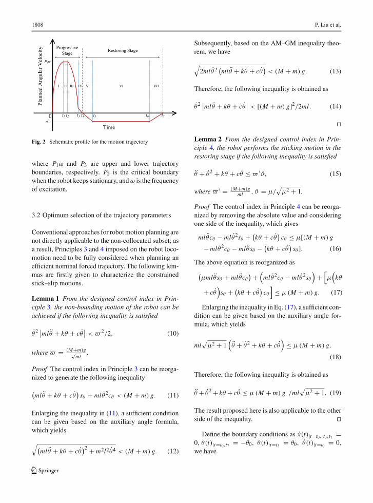
Table 1 Trajectory parameters for numerical simulation
Trajectories t1 (s) t2 (s) t3 (s) t4 (s) t5 (s) t6 (s) t7 (s)
Trajectory EPC 0.1 0.33 0.9 1.4 5.8 6.6 NA
Trajectory(9) 0.133 0.195 0.27 0.9 1.7 5.8 6.6
Fig. 3 Trajectory trackingperformance
Fig. 4 Robot displacementfor five cycles
Fig. 5 Input torques forfive cycles
123

1814 P. Liu et al.
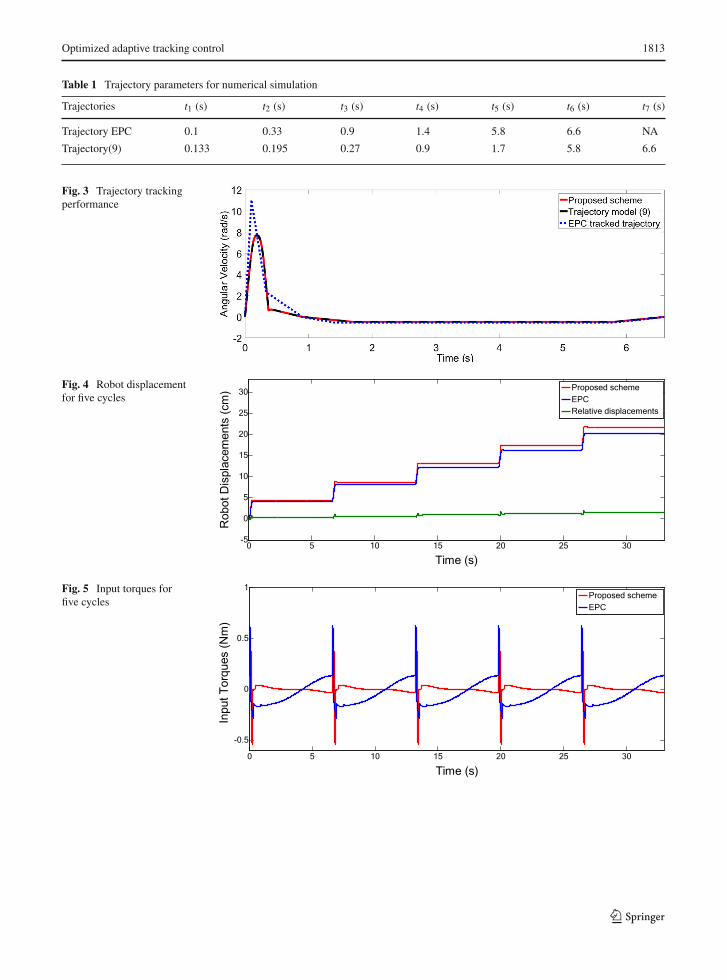
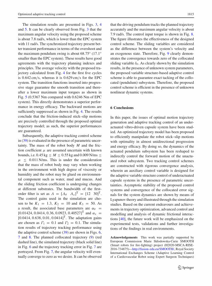
Fig. 6 Trajectory trackingperformances of controller(39)
Fig. 7 Trajectory trackingerror using controller (39)
Fig. 8 Control input torqueusing controller (39)
Fig. 9 Evolution of thecollocated sliding variableδθ
123
Optimized adaptive tracking control 1815
The simulation results are presented in Figs. 3, 4and 5. It can be clearly observed from Fig. 3 that themaximum angular velocity using the proposed schemeis about 7.8 rad/s, which is lower than the EPC systemwith 11 rad/s. The synchronized trajectory present bet-ter transient performance in terms of the overshoot andthe maximum pendulum swing is about 68.75◦ (17.1◦smaller than the EPC system). These results have goodagreements with the trajectory planning indexes andprinciples. The average velocity with the proposed tra-jectory calculated from Fig. 4 for the first five cyclesis 0.642 cm/s, whereas it is 0.629 cm/s for the EPCsystem. The transition functions inserted into progres-sive stage guarantee the smooth transition and there-after a lower maximum input torques as shown inFig. 5 (0.5367 Nm compared with 0.6246 Nm of EPCsystem). This directly demonstrates a superior perfor-mance in energy efficacy. The backward motions aresufficiently suppressed as shown in Fig. 4. The resultsconclude that the friction-induced stick–slip motionsare precisely controlled through the proposed optimaltrajectory model; as such, the superior performancesare guaranteed.
Subsequently, the adaptive tracking control schemein (39) is evaluated in the presence of parametric uncer-tainty. The mass of the robot body M and the fric-tion coefficient μ are assumed uncertain with knownbounds, i.e. 0.45 kg ≤ M ≤ 0.55 kg and 0.009N/ms ≤μ ≤ 0.011N/ms. This is under the considerationthat the mass of robot body may vary when workingin the environment with high degree of viscosity orhumidity and the robot may be glued on environmen-tal component such as water, mud and mucus. Andthe sliding friction coefficient is undergoing changesat different substrates. The bandwidth of the first-order filter is set as Λ = [Λθ Λx ]T = [12 30]T.The control gains used in the simulation are cho-sen to be K1 = 1.3, K2 = 10 and K3 = 50. Asa result, the associated base parameters are αθ =[0.01424, 0.0414, 0.36, 0.0923, 0.40527]T and αx =[0.0414, 0.638, 0.01, 0.0414]T. The adaptation gainsare chosen as Γ1 = 0.1 and Γ2 = 0.1. The simula-tion results of trajectory tracking performance usingthe adaptive control scheme (39) are shown in Figs. 6,7 and 8. The planned collocated trajectory (9) (reddashed line), the simulated trajectory (black solid line)in Fig. 6 and the trajectory tracking error in Fig. 7 areportrayed. From Fig. 7, the angular velocity will even-tually converge to zero as we desire. It can be observed
that the driving pendulum tracks the planned trajectoryaccurately and the maximum angular velocity is about7.9 rad/s. The control input torque is shown in Fig. 8.The figure illustrates the effectiveness of the designedcontrol scheme. The sliding variables are consideredas the difference between the system’s velocity andan exogenous state. Therefore, Fig. 9 clearly demon-strates the convergence towards zero of the collocatedsliding variable δθ . As clearly shown by the simulationresults, in the presence of unknown system parameters,the proposed variable structure-based adaptive controlscheme is able to guarantee exact tacking of the collo-cated (pendulum) subsystem. Therefore, the proposedcontrol scheme is efficient in the presence of unknownnonlinear dynamic systems.
6 Conclusions
In this paper, the issues of optimal motion trajectorygeneration and adaptive tracking control of an under-actuated vibro-driven capsule system have been stud-ied. An optimized trajectory model has been proposedto efficiently manipulate the robot stick–slip motionswith optimality in almost unidirectional progressionand energy efficacy. By doing so, the dynamics of theactuated pendulum subsystem has been reshaped toindirectly control the forward motion of the unactu-ated robot subsystem. Two tracking control schemesare constructed with rigorous convergence analysis,wherein an auxiliary control variable is designed forthe adaptive variable structure control of underactuatedcapsule systems in the presence of parametric uncer-tainties. Asymptotic stability of the proposed controlsystems and convergence of the collocated error sig-nals for the system dynamics are shown by means ofLyapunov theory and illustrated through the simulationstudies. Based on the current endeavours and achieve-ments in trajectory optimization, advanced control andmodelling and analysis of dynamic frictional interac-tions [40], the future work will be emphasized on theexperimental tests, validations and further investiga-tions of the findings in real environments.
Acknowledgements This work was partially supported byEuropean Commission Marie Skłodowska-Curie SMOOTH(Smart robots for fire-fighting) project (H2020-MSCA-RISE-2016-734875)—http://fusion-edu.eu/SMOOTH/, Royal SocietyInternational Exchanges Scheme (Adaptive Learning Controlof a Cardiovascular Robot using Expert Surgeon Techniques)
123

1816 P. Liu et al.
project (IE151224) and European Commission InternationalResearch Staff Exchange Scheme (IRSES) RABOT project(PIRSES-GA-2012-318902)—http://rabot.fusion-edu.eu/.
Compliance with ethical standards
Conflict of interest The authors declare that they have no con-flict of interest.
Open Access This article is distributed under the terms of theCreative Commons Attribution 4.0 International License (http://creativecommons.org/licenses/by/4.0/),whichpermits unrestricteduse, distribution, and reproduction in any medium, provided yougive appropriate credit to the original author(s) and the source,provide a link to the Creative Commons license, and indicate ifchanges were made.
References
1. Ergeneman, O., Chatzipirpiridis, G., Pokki, J., Marin-Suárez, M., Sotiriou, G.A., Medina-Rodriguez, S., Sánchez,J.F.F., Fernandez-Gutiérrez, A., Pane, S., Nelson, B.J.: Invitro oxygen sensing using intraocular microrobots. IEEETrans. Biomed. Eng. 59, 3104–3109 (2012)
2. Wang, Z., Gu, H.: A bristle-based pipeline robot for Ill-constraint pipes. IEEEASME Trans. Mechatron. 13, 383–392 (2008)
3. Sitti, M.: Miniature devices: voyage of the microrobots.Nature 458, 1121–1122 (2009)
4. Fang, H.-B., Xu, J.: Controlled motion of a two-modulevibration-driven system induced by internal acceleration-controlled masses. Arch. Appl. Mech. 82, 461–477 (2012)
5. Tang, Y., Chen, C., Khaligh, A., Penskiy, I., Bergbreiter, S.:An ultracompact dual-stage converter for driving electro-static actuators in mobile microrobots. IEEE Trans. PowerElectron. 29, 2991–3000 (2014)
6. Rashid, M.T., Frasca, M., Ali, A.A., Ali, R.S., Fortuna, L.,Xibilia, M.G.: Artemia swarm dynamics and path tracking.Nonlinear Dyn. 68, 555–563 (2012)
7. Becker, T.C., Mahin, S.A.: Effect of support rotation ontriple friction pendulum bearing behavior. Earthq. Eng.Struct. Dyn. 42, 1731–1748 (2013)
8. Kim, H.M., Yang, S., Kim, J., Park, S., Cho, J.H., Park,J.Y., Kim, T.S., Yoon, E.-S., Song, S.Y., Bang, S.: Activelocomotion of a paddling-based capsule endoscope in anin vitro and in vivo experiment (with videos). Gastrointest.Endosc. 72, 381–387 (2010)
9. Eigoli, A.K., Vossoughi, G.R.: Dynamic analysis of micro-robots with Coulomb friction using harmonic balancemethod. Nonlinear Dyn. 67, 1357–1371 (2012)
10. Ciuti, G., Valdastri, P., Menciassi, A., Dario, P.: Roboticmagnetic steering and locomotion of capsule endoscope fordiagnostic and surgical endoluminal procedures. Robotica28, 199–207 (2010)
11. Yim, S., Gultepe, E., Gracias, D.H., Sitti, M.: Biopsy using amagnetic capsule endoscope carrying, releasing, and retriev-ing untetheredmicrogrippers. IEEETrans. Biomed. Eng. 61,513–521 (2014)
12. Liu, Y.,Wiercigroch,M., Pavlovskaia, E., Yu, H.:Modellingof a vibro-impact capsule system. Int. J. Mech. Sci. 66, 2–11(2013)
13. Liu, Y., Pavlovskaia, E.,Wiercigroch,M.: Experimental ver-ification of the vibro-impact capsule model. Nonlinear Dyn.83, 1029–1041 (2016)
14. Liu, P.,Yu,H.,Cang, S.:Geometric analysis-based trajectoryplanning and control for underactuated capsule systemswithviscoelastic property. Trans. Inst. Meas. Control. 40, 2416–2427 (2017)
15. Ravichandran, M.T., Mahindrakar, A.D.: Robust stabiliza-tion of a class of underactuated mechanical systems usingtime scaling and Lyapunov redesign. IEEE Trans. Ind. Elec-tron. 58, 4299–4313 (2011)
16. Brockett, R.W., et al.: Asymptotic stability and feedbackstabilization. Differ. Geom. Control Theory 27, 181–191(1983)
17. Li, H., Furuta, K., Chernousko, F.L.: Motion generation ofthe capsubot using internal force and static friction. In: Pro-ceedings of the 45th IEEEConference onDecision andCon-trol, pp. 6575–6580. IEEE (2006)
18. Yu, H., Liu, Y., Yang, T.: Closed-loop tracking control of apendulum-driven cart-pole underactuated system. Proc. Inst.Mech. Eng. Part J. Syst. Control Eng. 222, 109–125 (2008)
19. Huda,M.N., Yu, H.: Trajectory tracking control of an under-actuated capsubot. Auton. Robots 39, 183–198 (2015)
20. Liu, P., Yu, H., Cang, S.: Modelling and control of an elasti-cally joint-actuated cart-pole underactuated system. In: 201420th International Conference on Automation and Comput-ing (ICAC), pp. 26–31. IEEE (2014)
21. Liu, P., Yu, H., Cang, S.: On periodically pendulum-divensystems for underactuated locomotion: a viscoelastic jointedmodel. Presented at the September (2015)
22. Xu, J.-X.,Guo, Z.-Q., Lee, T.H.:Design and implementationof integral sliding-mode control on an underactuated two-wheeled mobile robot. IEEE Trans. Ind. Electron. 61, 3671–3681 (2014)
23. Yu, R., Zhu, Q., Xia, G., Liu, Z.: Sliding mode trackingcontrol of an underactuated surface vessel. IET ControlTheory Appl. 6, 461–466 (2012). https://doi.org/10.1049/iet-cta.2011.0176
24. Huang, J., Guan, Z.-H., Matsuno, T., Fukuda, T., Sekiyama,K.: Sliding-mode velocity control of mobile-wheeledinverted-pendulum systems. IEEE Trans. Robot. 26, 750–758 (2010)
25. Adhikary, N., Mahanta, C.: Integral backstepping slidingmode control for underactuated systems: swing-up and sta-bilization of the cart-pendulum system. ISA Trans. 52, 870–880 (2013)
26. Blajer, W., Dziewiecki, K., Kołlodziejczyk, K., Mazur, Z.:Inverse dynamics of underactuated mechanical systems: asimple case study and experimental verification. Commun.Nonlinear Sci. Numer. Simul. 16, 2265–2272 (2011)
27. Erez, T., Todorov, E.: Trajectory optimization for domainswith contacts using inverse dynamics. In: 2012 IEEE/RSJInternational Conference on Intelligent Robots and Systems(IROS), pp. 4914–4919. IEEE (2012)
28. Mistry, M., Buchli, J., Schaal, S.: Inverse dynamics controlof floating base systems using orthogonal decomposition.In: 2010 IEEE International Conference on Robotics andAutomation (ICRA), pp. 3406–3412. IEEE (2010)
123
Optimized adaptive tracking control 1817
29. Xin, X., Yamasaki, T.: Energy-based swing-up control fora remotely driven Acrobot: theoretical and experimentalresults. IEEE Trans. Control Syst. Technol. 20, 1048–1056(2012)
30. Sun, N., Fang, Y., Zhang, X.: Energy coupling output feed-back control of 4-DOF underactuated cranes with saturatedinputs. Automatica 49, 1318–1325 (2013)
31. Albu-Schäffer,A., Petit,C.O.F.: Energy shaping control for aclass of underactuated Euler–Lagrange systems. IFAC Proc.45, 567–575 (2012)
32. Valentinis, F., Donaire, A., Perez, T.: Energy-based motioncontrol of a slender hull unmanned underwater vehicle.Ocean Eng. 104, 604–616 (2015)
33. Fortuna, L., Muscato, G.: A roll stabilization system for amonohull ship: modeling, identification, and adaptive con-trol. IEEE Trans. Control Syst. Technol. 4, 18–28 (1996)
34. Yang, C., Li, Z., Li, J.: Trajectory planning and optimizedadaptive control for a class of wheeled inverted pendulumvehicle models. IEEE Trans. Cybern. 43, 24–36 (2013)
35. Nguyen, K.-D., Dankowicz, H.: Adaptive control of under-actuated robots with unmodeled dynamics. Robot. Auton.Syst. 64, 84–99 (2015)
36. Hwang, C.-L., Chiang, C.-C., Yeh, Y.-W.: Adaptive fuzzyhierarchical sliding-mode control for the trajectory track-ing of uncertain underactuated nonlinear dynamic systems.IEEE Trans. Fuzzy Syst. 22, 286–299 (2014)
37. Yue, M., An, C., Du, Y., Sun, J.: Indirect adaptive fuzzycontrol for a nonholonomic/underactuated wheeled invertedpendulum vehicle based on a data-driven trajectory planner.Fuzzy Sets Syst. 290, 158–177 (2016)
38. Ghosh, A., Krishnan, T.R., Subudhi, B.: Robustproportional–integral–derivative compensation of aninverted cart-pendulum system: an experimental study. IETControl Theory Appl. 6, 1145–1152 (2012)
39. Tao, C.W., Taur, J., Chang, J.H., Su, S.-F.: Adaptive fuzzyswitched swing-up and sliding control for the double-pendulum-and-cart system. IEEE Trans. Syst. Man Cybern.Part B Cybern. 40, 241–252 (2010)
40. Liu, P., Yu, H., Cang, S.: Modelling and dynamic analy-sis of underactuated capsule systems with friction-inducedhysteresis. In: 2016 IEEE/RSJ International Conference onIntelligent Robots and Systems (IROS), pp. 549–554. IEEE(2016)
41. Pucci, D., Romano, F., Nori, F.: Collocated adaptive controlof underactuated mechanical systems. IEEE Trans. Robot.31, 1527–1536 (2015)
42. Fang, Y., Ma, B., Wang, P., Zhang, X.: A motion planning-based adaptive control method for an underactuated cranesystem. IEEE Trans. Control Syst. Technol. 20, 241–248(2012)
43. Spong, M.W.: Underactuated mechanical systems. In: Sicil-iano, B., Valavanis, K.P. (eds.) Control Problems inRoboticsand Automation, pp. 135–150. Springer, Berlin (1998)
123