Optimization of workpiece location and tool path movement ...
11
Optimization of workpiece location and tool path movement on CNC machining center using Genetic algorithm Shaymaa E. Sarhan,, Atef.A. Afifi , ELsayed Y. ElKady Sayed A. Wanies A b s t r a c t Due to the high running cost of CNC machines so the most studies are based on optimization of resident time of CNC by using such an optimization method according to the huge number of approached points in different machining features especially in multi components case. Most research in this area has concentrated on optimization of rapid movements (air time motion) and machining movements of drilling, pocketing, and face milling operations. Minimizing the machining time during chip generation by optimizing the cutting parameters, the tool sequence and the tool pathsto be used during cutting were studied by many researchers. However, the optimization of components location is not presented till now in spite of its effect on tool travel as well as machining cost. In this study, a methodology is developed to find the optimum location of a work-piece on the long table of a CNC milling machine which leads to minimum X, Y and Z axes movement between manufacturing features on different components. The near optimum location of the workpiece is set corresponding to the minimum movement of different axes and number of tool changes of the milling machine. A new methodology is used in this study using Genetic algorithm (GA) and Rank Order techniques to determine the near optimum location of the work-piece. (This save the energy consumption and improve the resident time) significantly. Keywords: CNC milling machine Workpiece location Optimization GA Rank Order “ 1. INTRODUCTION Vertical and horizontal machining centers are now used in a wide range of industries ranging from made to order companies where complex one-off jobs are the norm, to multi-component manufacturing companies where many smaller components are manufactured. Machining center utilization is not optimal. This is because in the one-off situation there is a tradeoffbetween the time spent in the hand preparation of the part program, and the time spent in machining. Thelatter often results in non-optimal machining center use; and, in the multi component situation, where a pallet (or long machine tables) is composed of up to thirty different components andrequires a tool magazine of over huge tools, the machine tool use is non-optimal for a number of reasons [1]. Typical factors which influence the optimally of use are: the location of component on the machine table or on the pallet, the sequence in which the tool are selected, and either the order in which the individual component part programs are called or the manner in which the multi –component part program is International Journal of Scientific & Engineering Research Volume 11, Issue 1, January-2020 ISSN 2229-5518 964 IJSER © 2020 http://www.ijser.org IJSER
Transcript of Optimization of workpiece location and tool path movement ...

Optimization of workpiece location and tool path movement on CNC
machining center using Genetic algorithm Shaymaa E. Sarhan,, Atef.A. Afifi, ELsayed Y. ElKady Sayed A. Wanies
A b s t r a c t Due to the high running cost of CNC machines so the most studies are
based on optimization of resident time of CNC by using such an
optimization method according to the huge number of approached points
in different machining features especially in multi components case.
Most research in this area has concentrated on optimization of rapid
movements (air time motion) and machining movements of drilling,
pocketing, and face milling operations. Minimizing the machining time
during chip generation by optimizing the cutting parameters, the tool
sequence and the tool pathsto be used during cutting were studied by
many researchers.
However, the optimization of components location is not presented till
now in spite of its effect on tool travel as well as machining cost.
In this study, a methodology is developed to find the optimum location of
a work-piece on the long table of a CNC milling machine which leads to
minimum X, Y and Z axes movement between manufacturing features on
different components. The near optimum location of the workpiece is set
corresponding to the minimum movement of different axes and number
of tool changes of the milling machine. A new methodology is used in this
study using Genetic algorithm (GA) and Rank Order techniques to
determine the near optimum location of the work-piece. (This save the
energy consumption and improve the resident time) significantly.
Keywords:
CNC milling machine Workpiece location Optimization GA Rank Order
“
1. INTRODUCTION
Vertical and horizontal machining centers are now used
in a wide range of industries ranging from made to order
companies where complex one-off jobs are the norm, to
multi-component manufacturing companies where
many smaller components are manufactured. Machining
center utilization is not optimal. This is because in the
one-off situation there is a tradeoffbetween the time
spent in the hand preparation of the
part program, and the time spent in machining. Thelatter
often results in non-optimal machining center use; and,
in the multi component situation, where a pallet (or long
machine tables) is composed of up to thirty different
components andrequires a tool magazine of over huge
tools, the machine tool use is non-optimal for a number
of reasons [1]. Typical factors which influence the
optimally of use are: the location of component on the
machine table or on the pallet, the sequence in which
the tool are selected, and either the order in which the
individual component part programs are called or the
manner in which the multi –component part program is
International Journal of Scientific & Engineering Research Volume 11, Issue 1, January-2020 ISSN 2229-5518
964
IJSER © 2020 http://www.ijser.org
IJSER

hand written for the entire pallet. These factors all
influence the residence time and in particular the non-
machining time (e.g., tool changes, pallet rotation,
movements between different components and
machining contours).
There has been much significant research interest
optimization. Most research in this area has
concentrated on productive time, non-productive time,
cutting conditions, optimization of tool
sequencepacking, .etc. Xiaorui Chen presented a new
methodology to offset multiplepolygonswith arbitrary
holes, where overlapping is prevented.[2]P Selvaraj
presented an algorithm to minimize the tool path for
pocket-milling using zig-zag method.[3]ZHIYANG YAOy
presented a methodology to generate a tool path by in
different regions of the geometry using different
patterns [4]. CuneytOysudeveloped an optimization
technique to minimize the non-productive time using a
hybrid algorithm (GA/SA)[5].Dorianadevelopedan
optimization technique based on genetic algorithms
(GA) to optimize the cutting parameters in
manufacturing[6]. Adnan Jameelpresented a review of
the near optimum cutting parameters and its variants in
turning using Genetic algorithm[7]. Ali Oralproposed an
optimization technique of tool sequences to be used for
turning in process planning
system[8].GjelajAfrimdeveloped an optimization
technique for tool selection using a genetic
algorithm[9].E. Hopperdeveloped an optimization
algorithm using hybrid technique used for optimizing the
packing of rectangular parts [10]. Mao Chendeveloped
an optimization technique to solve packing problem
used in two dimensional rectangular parts[11].
HaraldDyckhoffdeveloped a new approach used for
trimming and packing problems[12]. M.
ZahidGürbüzpresented an algorithm technique for
optimizing the 3D packing problem[13]. Nian-
ZeHupresented a new methodology to solve and
optimize a packing optimization problem. The developed
techniqueconverts the nonlinear objective function (of
the original packing problem) into a linear function with
the given parameters[14].Anandpresented a two-
dimensional nesting optimization methedology suitable
for a sheet metal industries employing profile blanking
laser cutting and processes[15].
This research is focused on developing the
methodologies required to optimize the non-productive
tool movements on a long machine table or on a pallet
faces of multi-component, multi-tool and multi axis
machines using generic computer –based techniques to
allocate the components on the available area on the
machine table or pallet using a new methodology
combined of Rank order technique and Genetic
optimization technique, while taking into account the
non-productive tool movement between the contours
on the different components which will result in the
reduction of non-machining time.
The reduction of non-machining time leads to total
residence time reduction as well as machining cost.
The Rank order Clustering technique which is mainly deals with clustering of parts into part families, and the machines into machine cells. Parts are grouped into part families based on similarities in their manufacturing and design attributes and the machines are allocated into machine cells to produce the identified part families. Zero-one part machine incidence matrix is commonly used as input to any clustering algorithm. Output is generated in the form of block diagonal structure. Many optimization techniques can be used to solve this problem, such as simulated genetic algorithm, annealing algorithm, ant-colony algorithm, neural network algorithm and genetic algorithm which be used to solve such a problem. A Genetic algorithm is a probabilistic search method that transforms a set of mathematical objects into a new set of objects. The set is called population, each object within the set have a fitness value. The objects Are usually fixed length binary character strings. New set is the new population contains some individuals from previous set added to it population of offspring based on Darwinian’s principle of natural selection and using operations such as crossover and mutation. Genetic algorithm search process includes survival of the fittest principle applied by selecting the individuals that adapt well to their environment which are the constraints. In other words, over the iterations which are the generations, individuals or the possible solutions that have characteristics required will remain within the Next generation instead of those with less desired characteristics. Selection of individuals is done stochastically depending on their fitness function.Crossover in GA complexity is according to wither an array have variable or fixed length. This paper proposes a new method for solving workpiece
allocation optimization problems based on Rank order technique and Genetic algorithm.
This problem has been solved by defining the available area on machine table or pallet, the dimension of each component, and the position of each contour relative to
International Journal of Scientific & Engineering Research Volume 11, Issue 1, January-2020 ISSN 2229-5518
965
IJSER © 2020 http://www.ijser.org
IJSER

its component origin, which will seek the minimization of non-productive tool movement.
2. PROBLEM FORMULATION
The proposed algorithm is implemented on Matlab software. The input is a text file that will be imported from a module of integrated developed software where each line represents a workpiece with its parameters (length, width, and fixture allowances) and the tools used for each workpiece, the whole file can be considered as initial solution of workpieces positions (represents one chromosome). The workpiece allocation optimization is seek to optimize the total residence time by minimizing the number of tool changes. The developed software minimize the number of tool changes by approaching the workpieces which used the same tools beside each other’s. Approaching the workpieces which used the same tools beside each other’s leads to minimization of tool path of each tool then minimization of non-productive time. This step is done by an idea taken from Rank order technique (with some changes) by calculating a factor which we named it as Totals Weight factor (T.W.F.). Where, T.W.F. is a summation of all weight factors of each used tool. Weight factors of each tool can be calculated using the following equation
Weight factor of tool j equation 1
Where n is the number of workpieces
equation 2
Where bis binary number equal to zero if workpiece
does not use such a tool and equal to 1 if workpiece uses
the tool.
As, shown in the following example
Table 1
Weight factor calculation
Weight factor of T1 = 0+0+0+0+21+22=6
Weight factor of T2 = 0+0+21+22+23+24=30
Weight factor of T3 =21+22+0+0+0+0=6
Weight factor of T4 =21+22+0+21+0+0=8
T.W.F. = 6+30+6+8=50
The workpiece allocation optimization problem is stated
as follows:
Maximize T.W.F.(Total weight factor)
Subject to
1. All of n workpieces are non-overlapping.
2. Workpiece orientation are allowed to fit the available
area of machine table (or pallet).
3. THE DEVELOPED METHEDOLOGY STEPS The developed technique used in this paper will be
explained through using a case study consists of 6
workpieces as follows (see table2).
Step 1: After having the initial solution which is given
from the imported text file (one chromosome), a random
population can be initialized by constructing 100
chromosomes based on that chromosome.
Step 2: calculate an integer weight factor for each tool
(column) using equation 1 and equation 2, and then
calculate the total weight factor of all 100 random
solutions (initial population) (see table1).
Step 3: (Parents selection) Selection is done using two
methods elitism and random method. In elitism the best
individuals are selected for a crossover, it can be done
easily since the population is already sorted. Random
method (which is used in this developed software): two
indices are randomly picked, the
solutions(chromosomes) at these indices will be the
Workpiece
ID
T1 T2 T3 T4
4 0 0 1 1
3 0 0 1 1
6 0 1 0 0
5 0 1 0 1
2 1 1 0 0
1 1 1 0 0
International Journal of Scientific & Engineering Research Volume 11, Issue 1, January-2020 ISSN 2229-5518
966
IJSER © 2020 http://www.ijser.org
IJSER
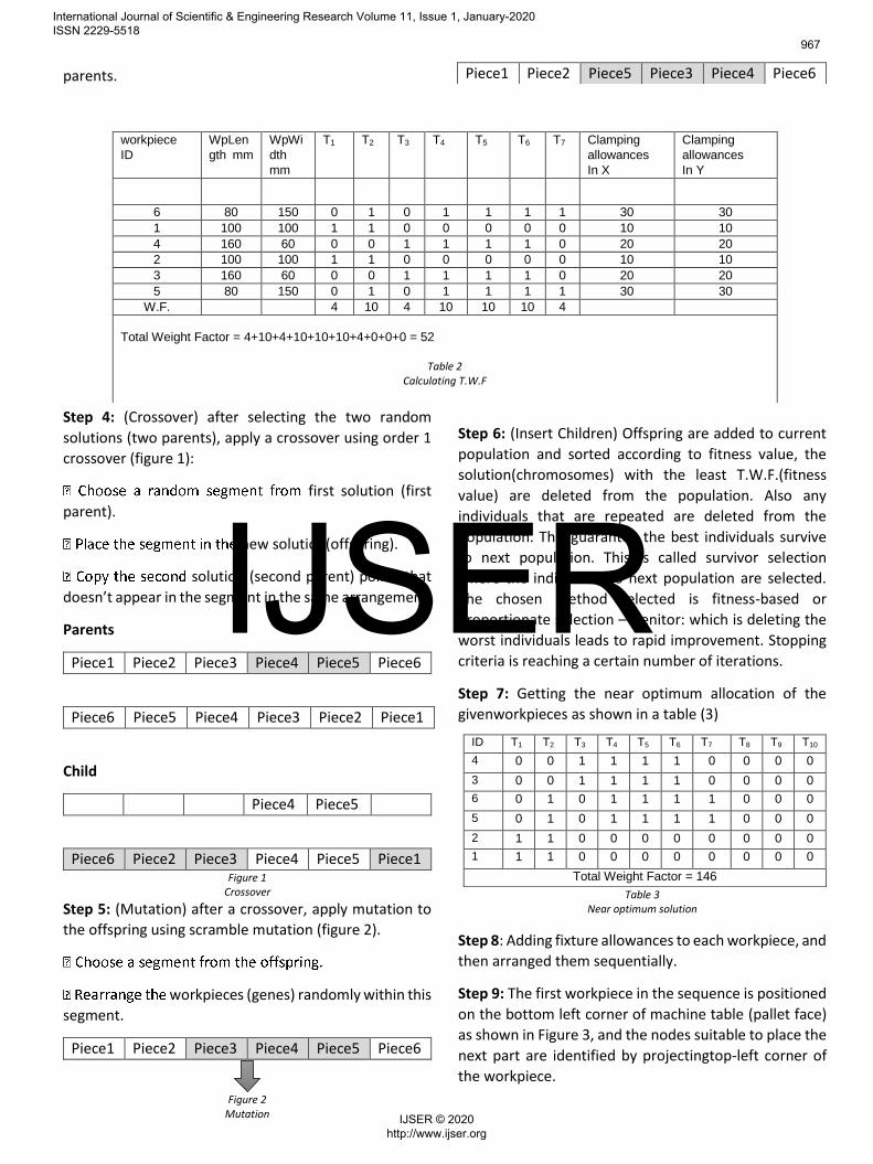
parents.
Step 4: (Crossover) after selecting the two random
solutions (two parents), apply a crossover using order 1
crossover (figure 1):
first solution (first
parent).
new solution(offspring).
solution (second parent) points that
doesn’t appear in the segment in the same arrangement.
Parents
Piece1 Piece2 Piece3 Piece4 Piece5 Piece6
Piece6 Piece5 Piece4 Piece3 Piece2 Piece1
Child
Piece4 Piece5
Piece6 Piece2 Piece3 Piece4 Piece5 Piece1 Figure 1
Crossover
Step 5: (Mutation) after a crossover, apply mutation to
the offspring using scramble mutation (figure 2).
workpieces (genes) randomly within this
segment.
Piece1 Piece2 Piece3 Piece4 Piece5 Piece6
Figure 2 Mutation
Step 6: (Insert Children) Offspring are added to current
population and sorted according to fitness value, the
solution(chromosomes) with the least T.W.F.(fitness
value) are deleted from the population. Also any
individuals that are repeated are deleted from the
population. This guarantee the best individuals survive
to next population. This is called survivor selection
where the individuals to next population are selected.
The chosen method selected is fitness-based or
proportionate selection – Genitor: which is deleting the
worst individuals leads to rapid improvement. Stopping
criteria is reaching a certain number of iterations.
Step 7: Getting the near optimum allocation of the
givenworkpieces as shown in a table (3)
Table 3 Near optimum solution
Step 8: Adding fixture allowances to each workpiece, and
then arranged them sequentially.
Step 9: The first workpiece in the sequence is positioned
on the bottom left corner of machine table (pallet face)
as shown in Figure 3, and the nodes suitable to place the
next part are identified by projectingtop-left corner of
the workpiece.
Piece1 Piece2 Piece5 Piece3 Piece4 Piece6
workpiece
ID WpLen
gth mm
WpWi
dth
mm
T1 T2 T3 T4 T5 T6 T7 Clamping
allowances
In X
Clamping
allowances
In Y
6 80 150 0 1 0 1 1 1 1 30 30
1 100 100 1 1 0 0 0 0 0 10 10
4 160 60 0 0 1 1 1 1 0 20 20
2 100 100 1 1 0 0 0 0 0 10 10
3 160 60 0 0 1 1 1 1 0 20 20
5 80 150 0 1 0 1 1 1 1 30 30
W.F. 4 10 4 10 10 10 4
Total Weight Factor = 4+10+4+10+10+10+4+0+0+0 = 52
Table 2 Calculating T.W.F
ID T1 T2 T3 T4 T5 T6 T7 T8 T9 T10
4 0 0 1 1 1 1 0 0 0 0
3 0 0 1 1 1 1 0 0 0 0
6 0 1 0 1 1 1 1 0 0 0
5 0 1 0 1 1 1 1 0 0 0
2 1 1 0 0 0 0 0 0 0 0
1 1 1 0 0 0 0 0 0 0 0
Total Weight Factor = 146
International Journal of Scientific & Engineering Research Volume 11, Issue 1, January-2020 ISSN 2229-5518
967
IJSER © 2020 http://www.ijser.org
IJSER
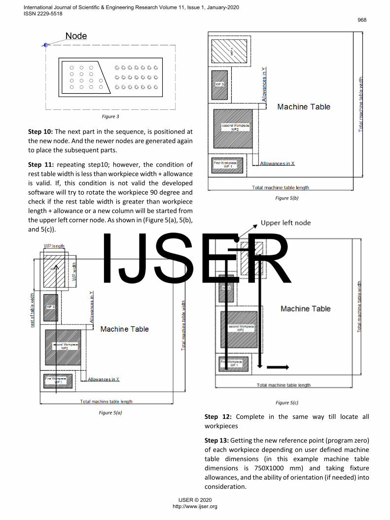
Figure 3
Step 10: The next part in the sequence, is positioned at
the new node. And the newer nodes are generated again
to place the subsequent parts.
Step 11: repeating step10; however, the condition of
rest table width is less than workpiece width + allowance
is valid. If, this condition is not valid the developed
software will try to rotate the workpiece 90 degree and
check if the rest table width is greater than workpiece
length + allowance or a new column will be started from
the upper left corner node. As shown in (Figure 5(a), 5(b),
and 5(c)).
Figure 5(a)
Figure 5(b)
Figure 5(c)
Step 12: Complete in the same way till locate all
workpieces
Step 13: Getting the new reference point (program zero)
of each workpiece depending on user defined machine
table dimensions (in this example machine table
dimensions is 750X1000 mm) and taking fixture
allowances, and the ability of orientation (if needed) into
consideration.
International Journal of Scientific & Engineering Research Volume 11, Issue 1, January-2020 ISSN 2229-5518
968
IJSER © 2020 http://www.ijser.org
IJSER

Step 14: applying the previous technique on the initial workpiece allocation (initial population) and near optimum solution and get the program zero (X and Y coordinates) and orientation (take the value 1 if the workpiece is rotated 90 degree to fit the rest space of the machine table) of each workpiece as shown in tables (3, 4).
Workpiece ID X coordinate of
program zero
Y coordinate of
program zero
Orientation
6 30 30 0
1 10 220 0
4 20 350 0
2 10 440 0
3 20 570 0
5 230 570 0
Table 4 Program zero of initial solution workpieces
Figure 6
Workpiece allocation of initial solution
Table 5 Program zero of near optimum solution workpieces
Using such a non-productive time optimization module
(using Genetic algorithm) for the initial population
allocation and near optimum solution allocation we get
Initial time = 2462.2 sec
Initial distance = 219530 mm
Final time = 625.6891 sec
Final distance = 74211 mm
Number of Tool Change= 9
Optimization = 74.5882 %
After applying the optimization of workpiece allocation
technique the results will be as follows:
Final time= 473.7941 sec
Final distance =54724mm
Number of Tool Change = 8
Optimization =80.7573 %
Workpiece
ID
X coordinate
of program
zero
Y coordinate of
program zero
Orientation
4 20 20 0
3 20 120 0
6 30 230 0
5 30 440 0
2 10 630 0
1 130 640 0
International Journal of Scientific & Engineering Research Volume 11, Issue 1, January-2020 ISSN 2229-5518
969
IJSER © 2020 http://www.ijser.org
IJSER

4. CASE STUDY Initial population of 22 workpieces allocation
Program zero of each workpiece of initial population
Workpiece
ID L W T1 T2 T3 T4 T5 T6 T7 Allowances
In X
Allowances
In Y
17 80 150 0 1 0 1 1 1 1 30 30
1 100 100 1 1 0 0 0 0 0 10 10
19 80 150 0 1 0 1 1 1 1 30 30
13 160 60 0 0 1 1 1 1 0 20 20
2 100 100 1 1 0 0 0 0 0 10 10
10 160 60 0 0 1 1 1 1 0 20 20
15 160 60 0 0 1 1 1 1 0 20 20
18 80 150 0 1 0 1 1 1 1 30 30
8 100 100 1 1 0 0 0 0 0 10 10
9 160 60 0 0 1 1 1 1 0 20 20
20 80 150 0 1 0 1 1 1 1 30 30
5 100 100 1 1 0 0 0 0 0 10 10
11 160 60 0 0 1 1 1 1 0 20 20
22 80 150 0 1 0 1 1 1 1 30 30
6 100 100 1 1 0 0 0 0 0 10 10
12 160 60 0 0 1 1 1 1 0 20 20
4 100 100 1 1 0 0 0 0 0 10 10
3 100 100 1 1 0 0 0 0 0 10 10
16 80 150 0 1 0 1 1 1 1 30 30
14 160 60 0 0 1 1 1 1 0 20 20
21 80 150 0 1 0 1 1 1 1 30 30
7 100 100 1 1 0 0 0 0 0 10 10
Workpiece ID X coordinate of program
zero
Y coordinate of program
zero
Orientation
17 30 30 0
1 10 220 0
19 30 410 0
13 20 610 0
2 210 640 0
10 220 530 0
15 160 430 0
18 170 230 0
8 150 90 0
9 160 20 0
20 370 30 0
5 290 220 0
11 300 350 0
22 430 460 0
6 550 640 0
12 560 550 0
4 550 420 0
3 490 300 0
16 510 110 0
14 640 20 0
21 650 130 0
7 670 320 0
International Journal of Scientific & Engineering Research Volume 11, Issue 1, January-2020 ISSN 2229-5518
970
IJSER © 2020 http://www.ijser.org
IJSER
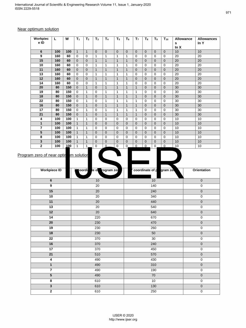
Near optimum solution
Program zero of near optimum solution
Workpiec
e ID L W T1 T2 T3 T4 T5 T6 T7 T8 T9 T10 Allowance
s
In X
Allowances
In Y
6 100 100 1 1 0 0 0 0 0 0 0 0 10 10
9 160 60 0 0 1 1 1 1 0 0 0 0 20 20
15 160 60 0 0 1 1 1 1 0 0 0 0 20 20
10 160 60 0 0 1 1 1 1 0 0 0 0 20 20
11 160 60 0 0 1 1 1 1 0 0 0 0 20 20
13 160 60 0 0 1 1 1 1 0 0 0 0 20 20
12 160 60 0 0 1 1 1 1 0 0 0 0 20 20
14 160 60 0 0 1 1 1 1 0 0 0 0 20 20
20 80 150 0 1 0 1 1 1 1 0 0 0 30 30
19 80 150 0 1 0 1 1 1 1 0 0 0 30 30
18 80 150 0 1 0 1 1 1 1 0 0 0 30 30
22 80 150 0 1 0 1 1 1 1 0 0 0 30 30
16 80 150 0 1 0 1 1 1 1 0 0 0 30 30
17 80 150 0 1 0 1 1 1 1 0 0 0 30 30
21 80 150 0 1 0 1 1 1 1 0 0 0 30 30
4 100 100 1 1 0 0 0 0 0 0 0 0 10 10
1 100 100 1 1 0 0 0 0 0 0 0 0 10 10
7 100 100 1 1 0 0 0 0 0 0 0 0 10 10
5 100 100 1 1 0 0 0 0 0 0 0 0 10 10
8 100 100 1 1 0 0 0 0 0 0 0 0 10 10
3 100 100 1 1 0 0 0 0 0 0 0 0 10 10
2 100 100 1 1 0 0 0 0 0 0 0 0 10 10
Workpiece ID X coordinate of program zero Y coordinate of program zero Orientation
6 10 10 0
9 20 140 0
15 20 240 0
10 20 340 0
11 20 440 0
13 20 540 0
12 20 640 0
14 220 670 0
20 230 470 0
19 230 260 0
18 230 50 0
22 370 30 0
16 370 240 0
17 370 450 0
21 510 570 0
4 490 430 0
1 490 310 0
7 490 190 0
5 490 70 0
8 610 10 0
3 610 130 0
2 610 250 0
International Journal of Scientific & Engineering Research Volume 11, Issue 1, January-2020 ISSN 2229-5518
971
IJSER © 2020 http://www.ijser.org
IJSER

Allocation of initial population
Allocation of near optimum solution
International Journal of Scientific & Engineering Research Volume 11, Issue 1, January-2020 ISSN 2229-5518
972
IJSER © 2020 http://www.ijser.org
IJSER

Initial time = 9135.3 sec
Initial distance = 863000 mm
Final time= 3310.5 sec
Final distance = 409320mm
Number of Tool Change =9
Optimization = 63.7611 %
After applying optimization of workpiece allocation
technique
Final time = 1986 sec
Final distance= 276620 mm
Number of Tool Change = 8
Optimization= 78.75 %
REFRENCES
5. CONCLUSION In this study, an optimization method is proposed to
determine the best location of the work-pieces
according to the common used tools and taking the
fixture allowances and no overlapping between
workpieces into consideration to minimization the
resident machining time. GA technique is used to
determine the optimum location of the workpiece origin
using such a technique like rank order technique.
However, the workpiece’s origin is determined by
another module starting with a first workpiece which is
put in the lower left corner of the machine table and get
the new node and so on. After, applying optimization of
the non-productive time for the initial and near optimum
location it is found that the near optimum location of
workpieces increases the optimization about 16% over
the optimization of non-productive time of the initial
workpiece location.
1) A. A. A. &. D. R. H. &, "Non-productive tool path
optimisation of multi-tool part programmes,"
Int J Adv Manuf Technol, p. 1007–1023, 2011.
2) X. Chen., "POLYGON OFFSETTING BY
COMPUTING WINDING NUMBERS," in
Proceedings of IDETC/CIE 2005..
3) P. Selvaraj, "Algorithm for Pocket Milling using
Zig-zag Tool Path,," Defence Science Journal, pp.
117-127, 2006.
4) Z. Y. a. S. Gupta., "Cutter path generation for
2.5D milling by combining multiple different
cutter path patterns.," International Journal of
Production Research, pp. 2141-2161, 2004.
5) Z. B. Cuneyt Oysu, "Application of heuristic and
hybrid-GASA algorithms to tool-path
optimization problem for minimizing airtime
during machining," Engineering Applications of
Artificial Intelligence, p. 389–396, 2009.
6) Doriana Roberto Teti, "Genetic algorithm-based
optimization of cutting parameters in turning
processes," in Forty Sixth CIRP Conference on
Manufacturing Systems, 2013.
7) A. Jameel, "Using Genetic Algorithm to
OptimizeMachining Parameters inTurning
Operation," International Journal of Scientific
and Research Publications, 2013.
8) *. M. C. C. Ali Orala, "Automated cutting tool
selection and cutting tool sequence
optimisation for rotational parts,," Robotics and
Computer-Integrated Manufacturing, p. 127–
141, 2004.
9) A. Gjelaj, "INTELLIGENT OPTIMAL TOOL
SELECTIONS FOR CNC PROGRAMMING OF
MACHINE TOOLS," TRANSACTIONS OF
FAMENA, 2013.
10) B. T. E. Hopper, "A Genetic Algorithm for a 2D
Industrial Packing Problem. Computers and,"
Industrial Engineering, pp. 375-378., 1999.
11) M. Chen., "A two-level search algorithm for 2D
rectangular packing problem," Computers &
Industrial Engineering, p. 123–136, 2007.
12) H. DYCKHOFF., "A typology of cutting and
packing problems," European Journal of
Operational Research, pp. 145-159, 1990.
International Journal of Scientific & Engineering Research Volume 11, Issue 1, January-2020 ISSN 2229-5518
973
IJSER © 2020 http://www.ijser.org
IJSER

13) S. A. M.Zahid Gürbüz, "An Efficient Algorithm
for 3D Rectangular Box Packing," Applied
Automatic Systems: Proceedings of Selected,
2009.
14) 1. H.-L. L. Nian-Ze Hu, "Solving Packing
Problems by a Distributed Global Optimization
Algorithm," Mathematical Problems in
Engineering Volume, 2012.
15) A. R. B. K. Vijay Anand, "Heuristic and genetic
approach for nesting of two-dimensional
rectangular shaped parts with common cutting
edge concept for laser cutting and profile
blanking," processes Computers & Industrial
Engineering, 2015.
International Journal of Scientific & Engineering Research Volume 11, Issue 1, January-2020 ISSN 2229-5518
974
IJSER © 2020 http://www.ijser.org
IJSER