Optimization of the Magnetic Field Topology in the Hall ...topologies (B1, B2, and B4) have been...
18
Optimization of the Magnetic Field Topology in the Hall Effect Rocket with Magnetic Shielding Hani Kamhawi ‡ , Wensheng Huang * National Aeronautics and Space Administration Glenn Research Center, Cleveland, OH, 44135, USA and Ioannis Mikellides § Jet Propulsion Laboratory, California Institute of Technology, Pasadena, CA, 91109, USA Abstract NASA’s Hall Effect Rocket with Magnetic Shielding (HERMeS) 12.5kW Technology Demonstration Unit-1 (TDU-1) has been the subject of extensive technology maturation in preparation for flight system development. The TDU-1 thruster implements a magnetically shielded field topology and has demonstrated the elimination of the discharge channel erosion as a life limiting mechanism. Extensive wear testing the TDU Hall thrusters has identified the thruster front pole covers as the next life limiting component. This effort aims to explore and investigate alternate magnetic field topologies to assess whether reductions in the front pole cover erosion can be attained while still maintaining very low erosion rates on the discharge channel walls. NASA GRC and JPL have begun a magnetic field topology characterization and optimization study by designing four candidate magnetic field topologies that reduce the effectiveness of the shielding along the discharge channel walls with the intent to also reduce the erosion rates along the front pole covers. Three of the four candidate magnetic field topologies (B1, B2, and B4) have been manufactured and will be subjected to an extensive test campaign that includes performance, plume, and stability characterization. In Phase I test segment, the thruster’s oscillation magnitude and laser induced fluorescence measurements were performed for the three candidate topologies. Phase I test results found that the B1 configuration attained lower oscillation levels than the baseline topology (B0). Additionally, laser induced fluorescence measurements along the discharge chamber centerline found that upstream retraction of the thruster’s peak magnetic field does result in an upstream shift of the acceleration zone but the magnitude of the shift does not correspond one-to-one to the shift in the location of the peak radial magnetic field magnitude. Phase II test segment will include performing performance, stability, plume, and erosion measurements for the various candidate magnetic field topologies. I. Introduction For missions beyond low Earth orbit, spacecraft size and mass can be dominated by onboard chemical propulsion systems and propellants that may constitute more than 50% of spacecraft mass. This impact can be substantially reduced through the utilization of Solar Electric Propulsion (SEP) due to its substantially higher specific impulse capability. Studies performed for NASA’s Human Exploration and Operations Mission Directorate (HEOMD) and Science Mission Directorate have demonstrated that a 40kW-class SEP capability can be enabling for both near term and future architectures and science missions. [1] Since 2012 NASA has been developing a 13.3 kW Hall thruster electric propulsion string that can serve as the building block for realizing a 40 kW-class SEP capability. NASA continues to evolve a human exploration approach for beyond low-Earth orbit and to do so, where practical, in a manner involving international, academic, and industry partners. [2] NASA publicly presented a reference exploration concept at the HEOMD Committee of the NASA ‡ Ion Propulsion System Test Lead, EP Systems Branch, [email protected], Associate Fellow AIAA. * Ion Propulsion System Diagnostics Lead, EP Systems Branch, [email protected], Senior Member AIAA. § Principal Engineer, Electric Propulsion Group, [email protected], Associate Fellow AIAA. https://ntrs.nasa.gov/search.jsp?R=20190001136 2020-03-02T03:42:44+00:00Z
Transcript of Optimization of the Magnetic Field Topology in the Hall ...topologies (B1, B2, and B4) have been...

Optimization of the Magnetic Field Topology in the Hall Effect Rocket with Magnetic Shielding
Hani Kamhawi‡, Wensheng Huang*
National Aeronautics and Space Administration Glenn Research Center, Cleveland, OH, 44135, USA and
Ioannis Mikellides§ Jet Propulsion Laboratory, California Institute of Technology, Pasadena, CA, 91109, USA
Abstract
NASA’s Hall Effect Rocket with Magnetic Shielding (HERMeS) 12.5kW Technology Demonstration Unit-1 (TDU-1) has been the subject of extensive technology maturation in preparation for flight system development. The TDU-1 thruster implements a magnetically shielded field topology and has demonstrated the elimination of the discharge channel erosion as a life limiting mechanism. Extensive wear testing the TDU Hall thrusters has identified the thruster front pole covers as the next life limiting component. This effort aims to explore and investigate alternate magnetic field topologies to assess whether reductions in the front pole cover erosion can be attained while still maintaining very low erosion rates on the discharge channel walls. NASA GRC and JPL have begun a magnetic field topology characterization and optimization study by designing four candidate magnetic field topologies that reduce the effectiveness of the shielding along the discharge channel walls with the intent to also reduce the erosion rates along the front pole covers. Three of the four candidate magnetic field topologies (B1, B2, and B4) have been manufactured and will be subjected to an extensive test campaign that includes performance, plume, and stability characterization. In Phase I test segment, the thruster’s oscillation magnitude and laser induced fluorescence measurements were performed for the three candidate topologies. Phase I test results found that the B1 configuration attained lower oscillation levels than the baseline topology (B0). Additionally, laser induced fluorescence measurements along the discharge chamber centerline found that upstream retraction of the thruster’s peak magnetic field does result in an upstream shift of the acceleration zone but the magnitude of the shift does not correspond one-to-one to the shift in the location of the peak radial magnetic field magnitude. Phase II test segment will include performing performance, stability, plume, and erosion measurements for the various candidate magnetic field topologies.
I. Introduction
For missions beyond low Earth orbit, spacecraft size and mass can be dominated by onboard chemical propulsion systems and propellants that may constitute more than 50% of spacecraft mass. This impact can be substantially reduced through the utilization of Solar Electric Propulsion (SEP) due to its substantially higher specific impulse capability. Studies performed for NASA’s Human Exploration and Operations Mission Directorate (HEOMD) and Science Mission Directorate have demonstrated that a 40kW-class SEP capability can be enabling for both near term and future architectures and science missions. [1]
Since 2012 NASA has been developing a 13.3 kW Hall thruster electric propulsion string that can serve as the building block for realizing a 40 kW-class SEP capability. NASA continues to evolve a human exploration approach for beyond low-Earth orbit and to do so, where practical, in a manner involving international, academic, and industry partners. [2] NASA publicly presented a reference exploration concept at the HEOMD Committee of the NASA
‡ Ion Propulsion System Test Lead, EP Systems Branch, [email protected], Associate Fellow AIAA. * Ion Propulsion System Diagnostics Lead, EP Systems Branch, [email protected], Senior Member AIAA. § Principal Engineer, Electric Propulsion Group, [email protected], Associate Fellow AIAA.
https://ntrs.nasa.gov/search.jsp?R=20190001136 2020-03-02T03:42:44+00:00Z

2
Advisory Council meeting on March 28, 2017. [3] This approach is based on an evolutionary human exploration architecture, depicted in Fig. 1, expanding into the solar system with cis-lunar flight testing and validation of exploration capabilities before crewed missions beyond the earth-moon system and eventual crewed Mars missions. One of the key objectives is to achieve human exploration of Mars and beyond through the prioritization of those technologies and capabilities best suited for such a mission in accordance with the stepping stone approach to exploration. [4] High-power solar electric propulsion is one of those key technologies that has been prioritized because of its significant exploration benefits. A high-power, 40 kW-class Hall thruster propulsion system provides significant capability and represents, along with flexible blanket solar array technology, a readily scalable technology with a clear path to much higher power systems. [5]
The 13.3 kW Hall thruster system development, led by the NASA Glenn Research Center (GRC) and the Jet Propulsion Laboratory (JPL), began with maturation of the high-power Hall thruster and power processing unit. The technology development work has transitioned to Aerojet Rocketdyne via a competitive procurement selection for the Advanced Electric Propulsion System (AEPS) contract. The AEPS contract includes the development, qualification, and multiple flight 14 kW electric propulsion string deliveries. [6] The AEPS Electric Propulsion (EP) string consists of the Hall thruster, power processing unit (including digital control and interface functionality), xenon flow controller, and associated intra-string harnesses. NASA continues to support the AEPS development leveraging in-house expertise, plasma modeling capability, and world-class test facilities. NASA also executes AEPS and mission risk reduction activities to support the AEPS development and mission application. [7]
Figure 1. NASA Human Exploration Vision including Lunar Orbital Platform- Gateway (LOP-G).[2]
This paper is organized as follow: in Section II a summary of the HERMeS thrusters test campaign at NASA
GRC is presented; in Section III the motivation for this effort is presented; in Section IV details about the new magnetic field topologies that will be investigated and assessed is presented; in Section V Hall2De numerical modeling results for the 4 candidate magnetic field topologies is presented; in Section VI overall campaign test plan is overviewed; in Section VII the experimental setup and the diagnostics that will be employed in this effort are summarized; in Section VIII results from the Phase I tests are presented; and in Section IX paper summary, conclusions, and future work is presented.

3
II. Background
NASA’s Hall Effect Rocket with Magnetic Shielding (HERMeS) 12.5 kW TDU-1 has been the subject of extensive technology maturation in preparation for flight system development starting in 2014. [8,9,10,11,12] A number of tests were performed on the thruster, the results of these tests were presented in 2016. [13,14,15,16,17,18] The tests assessed the performance, stability, facility effects, and thermal operation of the HERMeS thruster.
A graphite front pole cover thruster configuration with the thruster body electrically tied to cathode was selected as the thruster’s baseline configuration. [13,14] Performance characterization tests found that higher thruster performance was attained with the graphite front pole cover configuration and the thruster electrically tied to cathode. A total thrust efficiency of 68% and a total specific impulse of 2,820 sec were demonstrated at a discharge voltage of 600 V and a discharge power of 12.5 kW. Thruster stability regimes were characterized with respect to the thruster discharge current oscillations (discharge current peak-to-peak (Pk2Pk) and root mean square (RMS) magnitudes), along with maps of the current-voltage-magnetic field (IVB). Background pressure variation characterization tests were performed over a range of pressures from 4.6 to ~26 µTorr-Xe. For that background pressure range thruster performance and stability were shown to be mostly invariant to changes in the facility background pressure for pressures below 10 µTorr-Xe (for thruster flow rates of 20.2 mg/s and above). Power spectral density (PSD) analysis of the discharge current waveforms found that increasing the background pressure resulted in a higher discharge current dominant frequency with the PSD profiles shifting to the right with increased facility background pressure. [13] Finally, the IVB maps of the TDU-1 thruster indicated the thruster’s operation became more oscillatory at discharge voltages of ~ 450 V and that the thruster transitioned to a more oscillatory mode at 500 V and 600 V as can be seen in Fig. 2. [13] Detailed plume characterization of the TDU-1 and TDU-3 thrusters was performed.[15,19] Results from the plume characterization results found that TDU-1 and TDU-3 plume profiles had an almost identical profiles. Figure 3 presents the ion energy per charge profiles for TDU-1 during VF-5 testing at NASA GRC. Results in Fig. 3 are presented for 300 V 9.4 kW and 400 V 12.5 kW operation. Both profiles show that primary ions were detected at the 90º polar angles. This is critical because, if of sufficient flux, those primary ions can erode spacecraft surfaces causing them to degrade over the mission duration. The presence of these energetic primary ions at large plume angles can potentially complicate EP system integration to the spacecraft.
Figure 3. TDU-1 thruster ion energy per charge profiles at various background pressures for the 300 V 9.4 kW (left) and 400 V 12.5 kW throttle points at a polar angle of 90º. [15]
Figure 2. TDU-3 IVB map of discharge current RMS at 20.6mg/s at a CFF of 7% for discharge voltages of 100V to 610V and normalized magnetic field strength of 1 to 2.
4
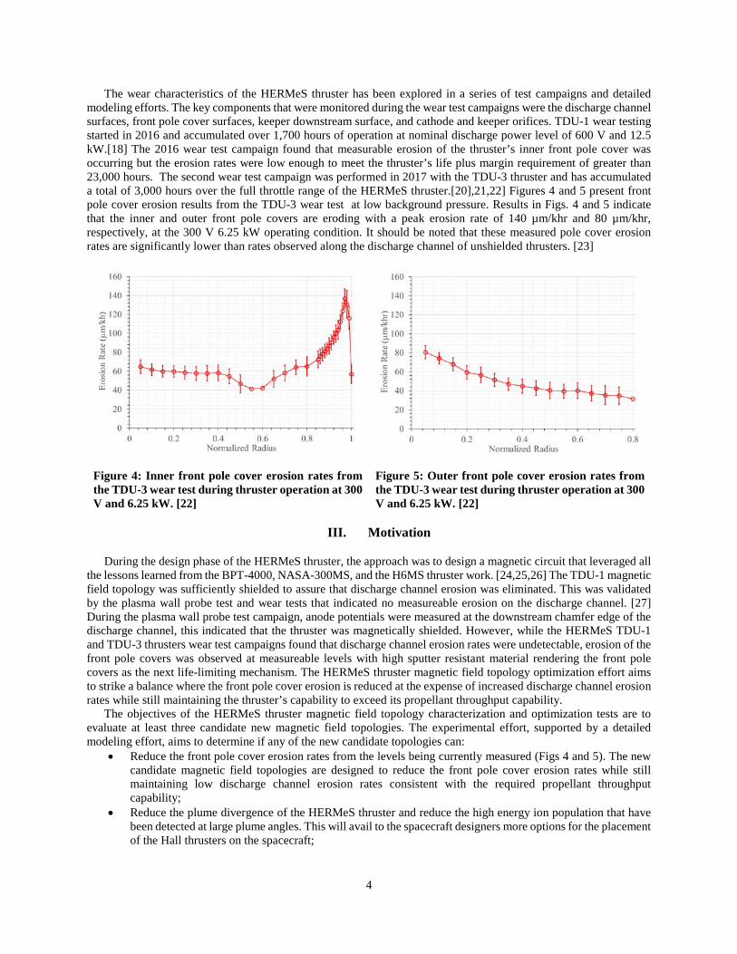
The wear characteristics of the HERMeS thruster has been explored in a series of test campaigns and detailed modeling efforts. The key components that were monitored during the wear test campaigns were the discharge channel surfaces, front pole cover surfaces, keeper downstream surface, and cathode and keeper orifices. TDU-1 wear testing started in 2016 and accumulated over 1,700 hours of operation at nominal discharge power level of 600 V and 12.5 kW.[18] The 2016 wear test campaign found that measurable erosion of the thruster’s inner front pole cover was occurring but the erosion rates were low enough to meet the thruster’s life plus margin requirement of greater than 23,000 hours. The second wear test campaign was performed in 2017 with the TDU-3 thruster and has accumulated a total of 3,000 hours over the full throttle range of the HERMeS thruster.[20],21,22] Figures 4 and 5 present front pole cover erosion results from the TDU-3 wear test at low background pressure. Results in Figs. 4 and 5 indicate that the inner and outer front pole covers are eroding with a peak erosion rate of 140 µm/khr and 80 µm/khr, respectively, at the 300 V 6.25 kW operating condition. It should be noted that these measured pole cover erosion rates are significantly lower than rates observed along the discharge channel of unshielded thrusters. [23]
Figure 4: Inner front pole cover erosion rates from the TDU-3 wear test during thruster operation at 300 V and 6.25 kW. [22]
Figure 5: Outer front pole cover erosion rates from the TDU-3 wear test during thruster operation at 300 V and 6.25 kW. [22]
III. Motivation
During the design phase of the HERMeS thruster, the approach was to design a magnetic circuit that leveraged all the lessons learned from the BPT-4000, NASA-300MS, and the H6MS thruster work. [24,25,26] The TDU-1 magnetic field topology was sufficiently shielded to assure that discharge channel erosion was eliminated. This was validated by the plasma wall probe test and wear tests that indicated no measureable erosion on the discharge channel. [27] During the plasma wall probe test campaign, anode potentials were measured at the downstream chamfer edge of the discharge channel, this indicated that the thruster was magnetically shielded. However, while the HERMeS TDU-1 and TDU-3 thrusters wear test campaigns found that discharge channel erosion rates were undetectable, erosion of the front pole covers was observed at measureable levels with high sputter resistant material rendering the front pole covers as the next life-limiting mechanism. The HERMeS thruster magnetic field topology optimization effort aims to strike a balance where the front pole cover erosion is reduced at the expense of increased discharge channel erosion rates while still maintaining the thruster’s capability to exceed its propellant throughput capability. The objectives of the HERMeS thruster magnetic field topology characterization and optimization tests are to evaluate at least three candidate new magnetic field topologies. The experimental effort, supported by a detailed modeling effort, aims to determine if any of the new candidate topologies can:
• Reduce the front pole cover erosion rates from the levels being currently measured (Figs 4 and 5). The new candidate magnetic field topologies are designed to reduce the front pole cover erosion rates while still maintaining low discharge channel erosion rates consistent with the required propellant throughput capability;
• Reduce the plume divergence of the HERMeS thruster and reduce the high energy ion population that have been detected at large plume angles. This will avail to the spacecraft designers more options for the placement of the Hall thrusters on the spacecraft;
5
• Improve the stability of the HERMeS thruster by reducing the oscillation levels during thruster operation particularly above 450 V. This effort will help elucidate whether any of the candidate new magnetic field topologies can impact when the mode transition to a high oscillatory mode occurs, and if the thruster still transitions to a high oscillatory mode, whether the magnitude of the oscillations can be reduced; and
• Reduce the magnetic circuit components saturation at high magnetic field settings which would permit the attainment of even higher magnetic field magnitudes while still maintaining the desired magnetic field topology.
IV. TDU-1 Magnetic Field Topology Optimization
Four new magnetic field topologies were designed. The new topologies present the first step in investigating new options for the HERMeS thruster magnetic field topology. In prior Hall thrusters designs the primary failure mechanism was erosion of the channel walls. [28] This is because the energy and flux of ions to the portion of these walls nearest to the channel exit yielded the highest erosion rates. Since this material resides between the high-energy ions and the magnetic circuit components, its loss by erosion would expose the latter to the former which would, eventually, lead to the failure of the thruster. Magnetic shielding of the Hall thruster is intended to protect the channel walls from ion bombardment. In the 6-kW laboratory Hall thruster called the H6, where MS was incorporated in the thruster and then tested, channel wear was practically eliminated; the erosion rates were reduced by a few orders of magnitude, MS achieves this by applying the magnetic field in a way that sustains high plasma potential and low electron temperature near the channel surfaces. [29,30,31] In this way the incident-ion kinetic and sheath energies can be marginalized. Moreover, with a properly designed combination of magnetic field and channel geometry, the electric field can be controlled to be both nearly perpendicular to the surface and large in magnitude, to force ion acceleration away from walls without loss of propulsive performance. The MS topology also has the benefit of reducing the wall-incident ion flux from the primary ions.
To achieve these features the MS topology is, by design, more curved near the channel exit compared to non-MS topologies. The baseline MS configuration (to be termed “B0” hereinafter) in HERMeS has the location of maximum magnetic field strength at the channel centerline located further downstream than that in an unshielded thruster. Consequently, ion acceleration also occurs further downstream which can lead to a higher concentration of high-energy ions in the plume region with a greater distribution of primary ion vectors that would have been attenuated by the channel walls in an unshielded thruster. This greater distribution of ions can in turn lead to higher erosion of the poles from direct bombardment by these ions and has been observed in development MS Hall thrusters. [32] However, it has been argued that due to the plasma expansion, the density of this high-energy ion population would be too small to cause any significant erosion. Indeed, wear rates measured in HERMeS showed elevated pole erosion compared to an unshielded thruster but low enough such that the life requirement of the thruster could still be met by adding a pole cover. However, the addition of the thicker conductive pole covers represents a deviation from historical Hall thruster flight configurations, as such, this investigation will assess whether a more conventional pole cover configuration can be used and still meet the thruster’s mission needs. Additionally, the addition of a low sputter yield pole cover has led to potential issue of spacecraft contamination by a conducting material. This potential contamination issue has not been a concern in the past with historical flight Hall thrusters since the majority of eroded material was a dielectric and total volume lost over the life of the spacecraft was below the allowable threshold. Thus, as stated in the motivation for this study the reduction of pole cover erosion would be beneficial for spacecraft integration.
The aforementioned downstream movement of the maximum magnetic field and, in turn, of the ion acceleration zone were both driven by the original objective to eliminate channel erosion. This however, may not be necessary for a given mission, since a reduction of the channel erosion by two or even one order of magnitude compared to an unshielded thruster may enable the propellant throughput requirements to be satisfied. That is, it should be possible to “optimize” the MS topology in a manner that reduces the erosion of both the channel walls and the front pole covers to values that are sufficiently low to meet lifetime requirements, without adding any protective covers. Such optimization can be achieved by relaxing the curvature of the MS topology around the channel chamfers, which will naturally be followed by an upstream retraction of the maximum magnetic field. This in turn, results in an upstream retraction of the ion acceleration zone. The major difference between the baseline magnetic field topology and the new magnetic field topologies (to be termed B1 thru B4 hereinafter) was the upstream movement of the peak radial magnetic field along the thruster discharge chamber centerline, while simultaneously maintaining a balanced magnetic field on the inner and outer discharge channel internal walls. For this study this was accomplished by minor adjustments to the magnetic circuit. Depending on the findings from this study, further modifications to the magnetic circuit and discharge channel configuration could be performed to further refine to thruster’s surfaces erosion rates, if needed. It is anticipated that the new magnetic field topologies will result in a slight increase in the discharge channel

6
erosion rates but will reduce the front pole cover erosion rates. As such the magnetic field optimization work represents an attempt to balance erosion rates between two different thruster components while still maintaining the propellant throughput capability of the thruster.
To design the new magnetic field topologies, a commercial magnetic field solver was used. Four magnetic field topologies were designed (B1-B4). All four new topologies were then used to construct their respective magnetic field aligned meshes (MFAMs) in Hall2De and new simulations were performed to assess discharge channel erosion.
Three of the four potential modifications were fabricated for the TDU-1 thruster magnetic circuit. The configuration B3 was designed and assessed in the model but never built, it can be fabricated if test results from the other three configuration indicate that B3 configuration is needed (three magnetic circuit configuration were installed into the TDU-1 thruster and the magnetic field was mapped).
Figures 6 and 7 present the measured radial magnetic field profile along the discharge channel center line for the 4 magnetic field topologies. Those topologies include the baseline topology B0 and the three new topologies (B1, B2, and B4). Results in Figs. 6 and 7 confirm that the peak radial magnetic field moves upstream towards the thruster anode as we progress from the B0 to B4 (Fig. 6). This is accompanied by an increase of 25% in the radial magnetic field strength at the anode face as is shown in Fig. 7.
Figure 6. Closeup of the normalized Br magnitudes at the nominal magnetic field setting.
Figure 7. Closeup of the normalized Br magnitudes inside the discharge channel near the anode face.
Table 1 summarizes some key magnetic circuit performance parameters at the nominal magnetic field setting.
Results presented in Table 1 indicate that the peak radial magnetic field is moving upstream as we progress from B0 to B4. In addition, topology B4 required only 83% of topology B0 electromagnet current to achieve the nominal peak radial magnetic field strength along the discharge chamber centerline, this in turn reduces the ohmic self-heating of the electromagnet wire and reduces its temperature.
Table 1. Summary of key parameters of TDU-1 magnetic new field topologies relative to the TDU-1 baseline topology B0.
Normalized Location of Peak Br
Normalized Br, @ z/L = -0.75
Ratio of ImagBx/ImagB0
Config B0, baseline 0.33 0.055 100% Config B1, Set#1 0.28 0.062 93.0% Config B2, Set#2 0.24 0.064 89.6% Config B4, Set#4 0.20 0.068 83.7%
V. Modeling and Simulation
a. Methods: General Description of the Hall2de Code The numerical simulations presented in this paper have been performed with the Hall2De code, a two-dimensional
(2-D), axisymmetric computational solver of the conservation equations that govern the evolution of the partially ionized gas in Hall thrusters. The governing equations, numerical methodology, various thruster simulations and

7
comparisons with measurements have been presented elsewhere [33,34,35]. Here, we provide only a brief overview for completeness.
In Hall2De all governing equations are solved on a magnetic-field-aligned computational mesh (MFAM). The solution of the electron energy conservation equation is obtained semi-implicitly; the thermal conduction and current convection terms are implicit whereas all other terms are evaluated explicitly. Current conservation, incorporating Ohm’s law to solve for the electron current density, is also solved implicitly. Ohm’s law is solved in the frame of reference of the magnetic field with the electrical resistivity accounting for contributions from collisions of electrons with all other species. It is now widely accepted that transport of electrons in Hall thrusters is driven to a large extent by non-classical mechanisms, possibly by plasma turbulence [36,37,38,39,40,41]. In numerical simulations this non-classical transport has typically been modeled using an effective or “anomalous” collision frequency. Denoting this collision frequency as να, we impose in Hall2De a so-called transport coefficient function fα(r,z) and set να=fαωce with ωce denoting the electron cyclotron frequency. Our specification of fα is guided by plasma measurements whenever they exist. Examples of the empirically-guided anomalous collision frequency in Hall thrusters as implemented in Hall2De has been presented in several articles in the past (e.g. see Ref. [42]).
The default approach in Hall2De for obtaining the solution of the heavy-species conservation equations avoids discrete-particle methods. However, an option to invoke the Particle-in-Cell (PIC) method for ions is also available in the code (e.g. see [43]). The evolution of the (collision-less) neutral species is computed using line-of-sight formulations that account for their depletion through ionization[34]. If PIC is not invoked, ions are treated as an isothermal, cold (relative to the electrons) fluid, accounting for the drag force and the ion-pressure gradient. The equations of motion for ions are discretized in time using a semi-implicit predictor/multi-corrector [44] scheme. Though relaxation times for ions can be shown to be small enough inside the acceleration channel, such times can become exceedingly high in the near plume region. If modeled as a single fluid, convection of slow ions in the near plume will occur at the mean velocity, which is dominated by the momentum of the fast ions. This would in turn result in erroneously low particle densities in regions that reside outside the main beam. To circumvent this limitation Hall2De employs a multi-fluid algorithm described in more detail in [35]. In the present simulations we allow for three distinct ion fluids. Up to triply charged ions are also accounted for each of the three fluids yielding a total of nine ion momentum and nine ion continuity equations.
Recently the code has been updated to allow for easier implementation of different electrical BCs. This was motivated by recent experimental investigations of different electrical configurations in the H6MS [45] and Hall-effect Rocket with Magnetic Shielding (HERMeS). [13,14,46] The updates now allow for insulating, conducting and current-collecting conditions at any of the wall boundaries.
b. Computational Arrangement and Operating Conditions for the HERMeS MS Optimization Investigations
Typically in Hall2De, the MFAM spans a computational domain in r-z geometry that extends several times the thruster channel length in the axial direction, and encompasses the cathode boundary and the thruster centerline. In the present simulations the near-plume computational domain spanned approximately 8.75 and 12.5 times the acceleration channel length L in the radial and axial directions, respectively. A schematic of the computational domain for the HERMeS simulations is shown in Fig. 8.
The conservation equations solved by Hall2De are closed with boundary conditions (BC) at all surfaces. Referring to Fig. 8, we impose dielectric BCs at the outer and inner channel walls of the acceleration channel. For all dielectric-wall boundaries a zero-current condition is imposed. At the (conducting) anode we impose sheath BCs for the electron current density normal to the anode. Propellant injection is modeled as influx BCs and specified at edges emulating the thruster ports. At the cathode boundary the neutral particle flux, ion flux, plasma potential and electron temperature are specified. The far plume solution is subject to outflow BCs along which a zero-current condition and a fixed electron temperature are imposed. The computational domain and BCs have been described with greater detail in previous publications (e.g. see [43]). Though HERMeS has been tested and simulated under several operation conditions, ranging 300-800 V, 4.7-12.5 kW (15.6-31.3 A) [9], in these first MS optimization investigations we present results for only the high-power operating condition, 12.5 kW, 600 V (20.8 A).
c. Numerical Simulations The Hall2De simulations with MS topologies B0-B4 were performed using the most recent physics models of
HERMeS. Specifically, the anomalous collision frequency followed a spatial variation that is very similar to that reported by Lopez Ortega and Mikellides [43] for B0. Previous work with the unshielded (H6US) and shielded (H6MS) versions of the H6 thruster has suggested that a direct correlation exists between the location of the maximum

8
magnetic field and the manner in which the anomalous transport evolves axially inside the channel. In these simulations therefore we assume that the anomalous collision frequency follows the axial retraction of the maximum magnetic field. The simulations also accounted for the discharge oscillations which have been shown to affect significantly the erosion rates at discharge voltages >500 V and fixed discharge current (20.8A).[43]
Figure 8. Schematic of part of the computational region in the HERMeS simulations with Hall2De, depicting relevant naming conventions used throughout this article.
Time-averaged results for the electron temperature and plasma potential at 600 V and 20.8 A are shown in Fig. 9 left and right, respectively, with the solution for B1 shown at the top row and B4 at the bottom. The computed thrust in these simulations was found to vary by less than 2% between the four topologies and was within 5% of the measured value for B0. A close inspection of the results along the chamfered walls clearly illustrates how warmer electron temperatures and higher potential drops are allowed along these boundaries as the MS topologies are retracted relative to B0.
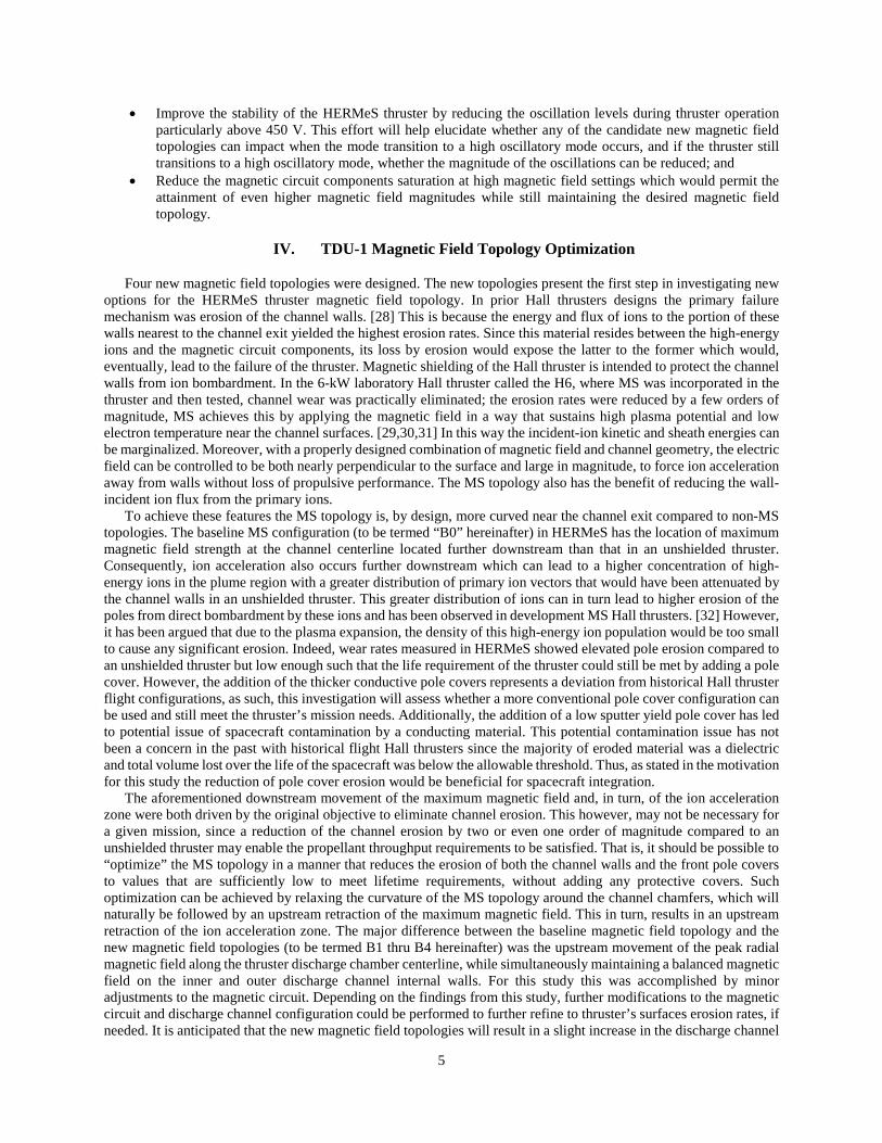
The erosion calculations used the same models for the sputtering yield as those described in [43], and accounted for contributions from three charge states (Xe+, Xe++ and Xe+++) and three ion fluids. The computed erosion along the inner channel wall for all MS topologies is compared in Fig. 10. As expected, the rates in going from B0 to B4 rise, with increasing values occurring further upstream from the channel exit along the chamfer. Similar results are found for the outer wall. Though the rates increase it is noted that the highest values observed in B4 remain approximately two orders of magnitude below those observed in the H6US. Moreover, at the maximum value of ~100 µm/kh (B4) and assuming that this value does not change as material is lost during thruster operation, it would take approximately 38 khr for the channel to be completely eroded. For reference, the specification for the HERMeS thruster calls for 23 khr of operation of the propulsion system that must be demonstrated with a 50% margin (34.5 kh). Thus even the worst magnetic field topology assessed in this investigation (B4) meets the HERMeS propellant throughput requirement. In reality, the wall is expected to erode away long after 38 kh since, as the wall material is lost, colder magnetic field lines are exposed which would begin to enhance again the effectiveness of the MS against ion bombardment. The impact on the front pole cover erosion based on the current simulations is still under investigation since part of the physics that drive erosion along these boundaries remains elusive. Nevertheless, the evidence from previous wear test results, not only of the HERMeS thruster but also those comparing pole erosion in MS and unshielded versions of the same thruster (e.g H6US vs. H6MS) suggest that pole erosion is expected to decrease as the magnetic field and, naturally the acceleration region, are retracted. Wear tests aimed at showing whether such reductions actually occur in going from B0 to B4 are underway.

9
Figure 9. Computed electron temperature (left) and plasma potential (right) from the numerical simulations with Hall2De employing topologies B1-B4.
Te (eV)908580757065605550454035302520151050
Phi (V)600550500450400350300250200150100500
Te (eV)908580757065605550454035302520151050
Phi (V)600550500450400350300250200150100500
Te (eV)908580757065605550454035302520151050
Phi (V)600550500450400350300250200150100500
Te (eV)908580757065605550454035302520151050
Phi (V)600550500450400350300250200150100500
B1
B2
B3
B4
10
Figure 10. Computed erosion rates along the inner channel wall of HERMeS for MS topologies B1-B4. Also shown for reference is the maximum rate measured in the 6-kW H6US. The chamfered region of the wall begins at z/L=0.875.
VI. Test Plan
A detailed test plan has been devised to evaluate the various magnetic field topologies B1 through B4. The test plan is outlined in Fig. 11. The TDU-1 thruster has been modified to facilitate exchanging the magnetic circuit components without having to remove the thruster from the test stand. Initial testing of configurations B1-B4 will be performed on the LIF test stand, designated Phase I, after which the thruster will be mounted on the VF6 thrust stand for Phase II of the test campaign. During the Phase I tests, configurations B1, B2, and B4 were tested starting with B4. During the Phase I test campaign, thruster bakeout was performed, then magnet maps (fix thruster operating power and discharge voltage and vary the radial magnetic field strength) were executed to assess the thruster’s oscillation levels, then LIF measurements were performed at 300 V 6.25 kW and 600 V 12.5 kW. The LIF measurements were performed along the discharge channel centerline, inside the discharge channel, at selected locations along the discharge chamfer region, and along selected locations on the inner and outer front pole covers. After completing the Phase I tests for configurations B1, B2 and B4, the thruster was removed from the LIF test stand, then the thruster underwent detailed surface mapping using a commercially available profilometer [22], and was then mounted on the VF6 thruster stand (shown in Fig. 12 behind the thruster). During the transition from Phase I to Phase II, the optical emission spectroscopy (OES) diagnostics was also installed and aligned, and the VF6 plasma diagnostics suite was realigned and checked out.
During the Phase II tests, configurations B1, B2, and B4 will be tested. For each configuration, performance will be measured during all test sequences including magnet maps. During the Phase II tests, OES measurements will be performed to elucidate how the discharge channel and front pole cover erosion is changing due to implementation of various magnetic field configurations. Additionally, plasma plume measurements will be performed using the VF6 plasma probe suite. Measurements will be performed using the Langmuir, retarding potential analyzer, Wien filter (E×B), and Faraday probes at various distances from the thruster. [15] Finally, a short duration wear test will be performed for selected magnetic field topology configurations (based on LIF and OES results) to assess the wear of the discharge channel and front pole covers at selected configurations.

11
Figure 11. Outline of the magnetic field topology optimization test campaign
VII. Experimental Apparatus
A test plan for the magnetic field optimization has been outlined in section VI. This section will briefly describe the thruster test hardware, vacuum chamber where testing will be performed, and will summarize the laser induced fluorescence (LIF) setup employed during Phase I of the test campaign.
a. Hall Effect Rocket with Magnetic Shielding TDU-1
The design of HERMeS TDU-1 incorporates technologies developed by NASA over nearly two decades. The thruster incorporates a magnetic shielding topology to eliminate discharge channel erosion as a life limiting mechanism.[47,48,49] The TDU-1, TDU-2, and TDU-3 thrusters employee a magnetically shielded magnetic field topology. The result is a significant increase in the operational lifetime, with HERMeS being designed to operate at 3,000 sec specific impulse and a projected life of > 50 kh. The TDU-3 thruster maintained key design features of the TDU-1 thruster which include: magnetic field topology, propellant manifold design, and discharge channel dimensions. The key difference between the TDU-1 and TDU-3 thruster was the grade of the discharge channel BN material; for TDU-1 it is heritage BN and for TDU-3 silica composite BN is used. Figure 12 shows a photograph of the 12.5 kW HERMeS TDU-1 thruster installed inside NASA GRC Vacuum Facility 6 (VF-6).
Testing of the HERMeS TDU-1 thruster was performed in VF-6 at NASA GRC.[50,51]. The VF-6 main chamber is 7.7 m in diameter, 27.6 m long, and is evacuated with 12 internal nude cryo pumps. For the test campaign discussed in this paper, the TDU-1 Hall thruster is located in the main volume of the chamber. Facility pressure was
Figure 12. TDU-1 installed on the LIF stages inside VF-6.

12
monitored with two xenon calibrated Stabil ion gauges. The power supplies, data acquisition, and propellant flow system have been previously used and are described in detail in Ref. [51]
b. Phase I Diagnostics: Laser Induced Fluorescence
During the Phase I test segment LIF measurements were performed. The LIF velocimetry scheme used in Phase I excites the XEII 834.953 nm (vac) transition and collects fluorescence from the 542.066 nm (vac) transition. [52] This singly-charged xenon ion transition has an unusually narrow hyperfine structure that cannot be easily resolved even when probed with special techniques. [53] At the same time, the narrowness of the hyperfine structure means that associated broadening in the lineshape for data obtained in the accelerating plasma of a Hall thruster is at most 4-5%. [53] Figure 13 shows a diagram of the LIF scheme used. The laser was a taper-amplified diode laser that output up to 500 mW at 835 nm. Wavelength was monitored via a Fizeau-type wavemeter and an optogalvanic cell. The laser beam entering the optogalvanic cell was mechanically chopped at ~1.6 kHz. The laser beam was also monitored with photodiode to track the variation in laser power. The laser beam was split into three branches. Each branch passed through a separate electro-optical modulator and was collimated into optical fibers. A modulation frequency study showed that the signal-to-noise ratio (SNR) optimized at around 300 kHz to 350 kHz in modulation frequency.
Figure 14 shows a diagram of the optics setup inside the vacuum facility. Three sets of injection optics where deployed. The optical fibers from the air-side setup were sent to each of the three sets of injection optics. Each set of injection optics had two motors that allowed remote control of the tilt and pan. The optics on axis 1, the axial axis, was protected from most of the heat of the plasma by a shield. The thruster COnfwas mounted to the motion stages that provide radial and axial movements (Fig. 12). A reference target was mounted at a known distance from the thruster in the same plane as the three injected laser beams. Two cameras monitored the positions of the injected laser beams relative to the reference target. The collection optics was mounted 70° out of the laser plane. An optical fiber carried fluorescence signal from the collection optics out of the vacuum facility. The light from the collection optical fiber was collimated into a Monochromator and sent to a photomultiplier. The photomultiplier current was converted to voltage via a high-speed trans-impedance amplifier. The output voltage signal was coupled into three digital lock-in amplifiers. A fourth digital lock-in amplifier measures the signal from the optogalvanic cell. A computer controls the movement of various stages, sweeps the laser wavelength, and records the various output signals.
Figure 13. Transition diagram for Xe II LIF at 834.953 nm (vac).
Figure 14. Vacuum side optical setup.

13
VIII. Test Results
Phase I test segment results will be reported in this paper. The following two sections will present results for the thruster magnetic field mapping and LIF tests. More detailed discussions of the results will be performed in a later publication since the performance, plume, and erosion data (data that will be collected in Phase II) is needed to fully analyze the data set presented in this paper.
a. Magnetic Field Mapping Results The TDU-1 thruster was operated with magnetic field topologies B1, B2, and B4. Operation with B0 configuration was performed prior to the magnetic field optimization study during the extended LIF test campaign. [52] During Phase I of this study the thruster’s oscillations were characterized for the thruster operating at 300-600 V at 20.8 A for configurations B1, B2, and B4. The magnetic field was varied between 75% and 125% of the nominal field value. Figure 15 presents the ratio of the discharge current to anode flow rate at the various magnetic field operating settings for configurations B0, B1, B2, and B4 for thruster operation at 300 to 600 V at a discharge current of ~20.8 A. The results show that for the most part the B1 and B2 profiles followed that of B0. However, B4 showed a significant deviation from the B0 profile. This is an indication that a substantial field retraction results in changes to the nature and characteristics of the plasma discharge.
Figure 15: Discharge current to anode flow ratios for configurations B0, B1, B2, and B4 for thruster operation at 300 V, 400 V, 500 V, and 600 V (propagated uncertainty in Id/ma is 2%).
Figure 16 presents profiles of the normalized discharge current RMS at the various magnetic field operating settings for configurations B0, B1, B2, and B4 for thruster operation at 300 to 600 V at a discharge current of ~20.8 A. The results show that configuration B1 had the lowest oscillation levels for all thruster operating conditions. Configuration B2 oscillation levels were similar for 300 V operation, higher at 400 V, and were lower at 500 and 600

14
V when compared to the baseline configuration B0. Configuration B4, resulted in higher oscillation levels for all thruster operating conditions. It is important to note here that during this segment of the test, the thruster for configurations B1, B2, and B4 still transitioned to a high oscillatory mode between 400 and 500V which qualitatively similar to B0 operation.
Figure 16: Normalized discharge current RMS values for configurations B0, B1, B2, and B4 for thruster operation at 300 V, 400 V, 500 V, and 600 V. b. Laser Induced Fluorescence Measurements Along Discharge Channel Center line Detailed LIF measurements were performed at 300 V 6.25 kW and 600 V 12.5 kW operating conditions at the nominal magnetic field setting. At each operating condition LIF measurements were performed along the discharge channel center line, inside the discharge channel region (2D), along the discharge channel chamfer walls and near the front pole covers. For this paper only results from the centerline LIF measurements will be presented. The reminder of the data is still being analyzed and will be presented in a later publication. Figures 17 and 18 present the LIF measurements for the 300 V 6.25 kW and 600 V 12.5 kW thruster operating conditions, respectively. For 300 V operation, the B1 configuration shifts the acceleration zone slightly upstream when compared to the baseline configuration. The B2 and B4 configurations extend the acceleration zone upstream by 6 and 7 times as much as B1, respectively. For 600 V operation, both B2 and B4 configurations extend the acceleration zone upstream by about 4 times as much as B1 relative to the baseline configuration.

15
Figure 17: Average ion velocity along the discharge channel centerline for thruster operation at 300 V and
6.25 kW for magnetic field topologies B0, B1, B2, and B4.
Figure 18: Average ion velocity along the discharge channel centerline for thruster operation at 600 V and
12.5 kW for magnetic field topologies B0, B1, B2, and B4.
IX. Conclusions, Summary, And Future Work
Extensive testing of the HERMeS thrusters (TDU-1, TDU-2, and TDU-3) has been performed at NASA GRC and JPL. Modeling and test results to date, have found that the thruster design meets the 23 kh life service capability with a 50% margin. However, in order to further refine the design, the NASA GRC and JPL team explored performing

16
modifications to the thruster magnetic field topology to reduce the front pole cover erosion rates, reduce plume divergence, improve thruster stability, and improve its magnetic circuit performance. Four new magnetic field topologies were designed at NASA GRC and they were numerically modeled by NASA JPL using Hall2De. Modeling of the four candidate magnetic field topologies found that, as expected, the discharge channel erosion rates in going from B0 to B4 rise, with increasing values occurring further upstream from the channel exit along the chamfer. Though the rates increase it is noted that the highest values observed in B4 remain approximately two orders of magnitude below those observed in the H6US. Moreover, at the maximum value of ~100 µm/kh (B4) it would take approximately 38 kh for the channel to be completely eroded (assuming that the rate does not change as material is lost during thruster operation). New magnetic circuit components were manufactured, installed, and the magnetic field topologies were measured along discharge channel CL and 2D map. The measured magnetic topologies were found to very closely match the designed magnetic field topologies. In Phase I, the thruster’s oscillation magnitude and LIF measurements were performed for the three candidate topologies. Lower oscillation levels were measured for the B1 configuration compared to the baseline B0 configuration. Additionally, LIF measurements along the discharge chamber centerline found that upstream retraction of the peak magnetic field does result in an upstream shift of the acceleration zone but the magnitude of the extension does not correspond one-to-one to the shift in the location of the peak magnetic field magnitude. The Phase II test segment will include performing performance, stability, plume, and erosion measurements on the various candidate magnetic field topologies.
Acknowledgments
The authors would like to like to thank the Space Technology Mission Directorate through the Solar Electric Propulsion Technology Demonstration Mission Project for funding the joint NASA GRC and JPL development of the Advanced Electric Propulsion System. The authors would also like to thank the many NASA/Aerojet review board members and subject matter experts for providing their expertise and technical guidance to the development of AEPS and its broader Ion Propulsion Subsystem mission application.
References
[1] Smith, B. K., Nazario, M. L., and Cunningham, C. C. "Solar Electric Propulsion Vehicle Demonstration to Support Future Space Exploration Missions," Space Propulsion 2012. Bordeaux, France, 2012.
[2] Free, J. "Architecture Status," NASA Advisory Council Human Exploration and Operations Committee Meeting. Washington, DC, 2017.
[3] Congress, t. "National Aeronautics and Space Administration Transition Authorization Act of 2017." 2017. [4] Leiter, H., Kukies, R., Killinger, R., Bonelli, E., Scaranzin, S., Scortecci, F., Neumann, H., and Tartz, M. "RIT-
22 Ion Propulsion System: 5,000h Endurance Test Results and Life Prediction." Cincinnati, OH, 2007. [5] Gerstenmaier, W. "Progress in Defining the Deep Space Gateway and Transport Plan," NASA Advisory Council
Human Exploration and Operations Committee Meeting, 2017 [6] Jackson, J., et al. “13kW Advanced Electric Propulsion Flight System Development and Qualification,” IEPC-
2017-223, 35th International Electric Propulsion Conference. ERPS, Atlanta, GA, 2017. [7] Hofer, R. R., and Kamhawi, H. "Development Status of a 12.5 kW Hall Thruster for the Asteroid Redirect Robotic
Mission," 35th International Electric Propulsion Conference. ERPS, Atlanta, GA, 2017. [8] Kamhawi, H., Huang, W., Haag, T. W., Yim, J., Chang, L., Clayman, L., Herman, D. A., Shastry, R., Thomas, R.,
Griffith, C., Myers, J., Williams, G. J., Mikellides, I., Hofer, R. R., Polk, J. E., and Goebel, D. M. "Overview of the Development of the Solar Electric Propulsion Technology Demonstration Mission 12.5-kW Hall Thruster," 50th AIAA/ASME/SAE/ASEE Joint Propulsion Conference. Cleveland, OH, 2014.
[9] Kamhawi, H., Haag, T., Huang, W., Herman, D. A., Thomas, R., Shastry, R., Yim, J., Chang, L., Clayman, L., Verhey, T., Griffiths, C., Myers, J., Williams, G., Mikellides, I. G., Hofer, R. R., Polk, J. E., and Jorns, B. A. "Performance Characterization of the Solar Electric Propulsion Technology Demonstration Mission 12.5-kW Hall Thruster," 34th International Electric Propulsion Conference. Kobe, Japan, 2015.
[10] Hofer, R. R., Kamhawi, H., Herman, D. A., Polk, J. E., Snyder, J. S., Mikellides, I., Huang, W., Myers, J., Yim, J., Williams, G. J., Lopez Ortega, A., Jorns, B., Sekerak, M., Griffiths, C., Shastry, R., Haag, T. W., Verhey, T. R., Gilliam, B., Katz, I., Goebel, D. M., Anderson, J. R., Gilland, J. H., and Clayman, L. "Development Approach and Status of the 12.5 kW HERMeS Hall Thruster for the Solar Electric Propulsion Technology Demonstration Mission," 30th International Electric Propulsion Conference. Kobe, Hyogo, Japan, 2015.

17
[11 ]Myers, J., Kamhawi, H., and Yim, J. "HERMeS Thermal Model," 51st Joint Propulsion Conference. Orlando,
FL, 2015. [12] Williams, G. J., and Kamhawi, H. "Optical characterization of component wear and near-field plasma of the
HERMeS thruster," 62nd JANNAF Propulsion Meeting. Nashville, TN, 2015. [13]Kamhawi, H., Haag, T. W., Huang, W., Herman, D. A., Williams, G. J., Peterson, P. Y., Hofer, R. R., and
Mikellides, I. "Performance, Stability, and Pressure Effects Characterization Tests of NASA’s 12.5-kW Hall Effect Rocket with Magnetic Shielding (HERMeS) Thruster," 52nd AIAA/SAE/ASEE Joint Propulsion Conference. Salt Lake City, UT, 2016.
[14] Peterson, P. Y., Kamhawi, H., Huang, W., Williams, G., Gilland, J., Yim, J., Hofer, R. R., and Herman, D. "NASA's HERMeS Hall Thruster Electrical Configuration Characterization," 52nd AIAA/ASME/SAE/ASEE Joint Propulsion Conference. AIAA, Salt Lake City, UT, 2016.
[15 ]Huang, W., Kamhawi, H., and Haag, T. W. "Facility Effect Characterization Test of NASA’s HERMeS Hall Thruster," 52nd AIAA/SAE/ASEE Joint Propulsion Conference. Salt Lake City, UT, 2016.
[16 ]Huang, W., Kamhawi, H., and Haag, T. W. "Plasma Oscillation Characterization of NASA’s HERMeS Hall Thruster via High Speed Imaging," 52nd AIAA/SAE/ASEE Joint Propulsion Conference. Salt Lake City, UT, 2016.
[17 ]Hofer, R. R., and Kamhawi, H. "Development Status of the 12.5 kW HERMeS Hall Thruster Solar Electric Propulsion Technology Demonstration Mission," 52nd AIAA/SAE/ASEE Joint Propulsion Conference. Salt Lake City, UT, 2016.
[18] Williams, G. J., Gilland, J. H., Peterson, P. Y., Kamhawi, H., Huang, W., Swiatek, M., Joppeck, C., Yim, J., and Haag, T. W. "Wear Testing of the HERMeS Thruster," 52nd AIAA/SAE/ASEE Joint Propulsion Conference. Salt Lake City, UT, 2016.
[19] Kamhawi,H., Huang, W., Gilland, J., Mackey, J., Yim, J., Pinero, L., Williams, G., Peterson, P., and Herman, D., “Performance, Stability, and Plume Characterization of the HERMeS Thruster with Boron Nitride Silica Composite (M26) Discharge Channel” in 65th JANNAF Propulsion Meeting, Long Beach, CA, 2018.
[20] G. Williams, J. H. Gilland, H. Kamhawi, M. Choi, P. Y. Peterson, and D. A. Herman, "Wear Trends of the HERMeS Thruster as a Function of Throttle Point," presented at the 35th International Electric Propulsion Conference, Atlanta, GA, 2017.
[21] P. Peterson, J. Frieman, H. Kamhawi, G. Williams, D. Herman, J. Gilland, and R. Hofer, “ NASA Hermes Hall Thruster Long Duration Wear Test,” in 65th JANNAF Propulsion Meeting, Long Beach, CA, 2018.
[22] Frieman, J., Kamhawi, H., Williams, G., Herman, D., Peterson, P, Gilland, J, and Hofer, H., “Long Duration Wear Test of the NASA HERMeS Thruster,” AIAA Propulsion and Energy Forum, Cincinnati, OH, Jul 9-11, 2018.
[23] R. R. Hofer, D. M. Goebel, I. G. Mikellides, and I. Katz, “Magnetic shielding of a laboratory Hall thruster. II. Experiments,” Journal of Applied Physics, vol. 115, no. 4, Jan 28, 2014.
[24] De Grys, K., Mathers, A., Welander, B., and Khayms, V., "Demonstration of 10,400 Hours of Operation on 4.5 kW Qualification Model Hall Thruster", 46th AIAA/ASME/SAE/ASEE Joint Propulsion Conference & Exhibit, Joint Propulsion Conferences
[25] R. R. Hofer, D. M. Goebel, I. G. Mikellides, and I. Katz, “Magnetic shielding of a laboratory Hall thruster. II. Experiments,” Journal of Applied Physics, vol. 115, no. 4, Jan 28, 2014.
[26] Kamhawi, H., Huang, W., Gilland, J., Mackey, J., Yim, J., Pinero, L., Williams, G., Peterson, P., and Herman, D., “Performance, Stability, and Plume Characterization of the HERMeS Thruster with Boron Nitride Silica Composite (M26) Discharge Channel” JANNAF
[27] R. Shastry, W. Huang, and H. Kamhawi, "Near-Surface Plasma Characterization of the 12.5-kW NASA TDU1 Hall Thruster," in 51st Joint Propulsion Conference, ed. Orlando, FL, 2015.
[28] C. Garner, J. R. Brophy, J. E. Polk, and L. C. Pless, "A 5730 Hr Cyclic Endurance Test of the SPT-100," in Joint Propulsion Conference, AIAA-95-2667, San Diego, CA, 1995.
[29] I. G. Mikellides, I. Katz, R. R. Hofer, and D. M. Goebel, “Magnetic shielding of a laboratory Hall thruster. I. Theory and validation,” Journal of Applied Physics, vol. 115, no. 4, Jan 28, 2014.
[30] R. R. Hofer, D. M. Goebel, I. G. Mikellides, and I. Katz, “Magnetic shielding of a laboratory Hall thruster. II. Experiments,” Journal of Applied Physics, vol. 115, no. 4, Jan 28, 2014.
[31] I. G. Mikellides, I. Katz, R. R. Hofer, and D. M. Goebel, “Magnetic shielding of walls from the unmagnetized ion beam in a Hall thruster,” Applied Physics Letters, vol. 102, no. 2, Jan 14, 2013.
[32] I. G. Mikellides, I. Katz, R. R. Hofer, D. M. Goebel, K. de Grys, and A. Mathers, “Magnetic shielding of the channel walls in a Hall plasma accelerator,” Physics of Plasmas, vol. 18, no. 3, pp. 033501, Mar, 2011.
[33] I. G. Mikellides, and I. Katz, “Numerical simulations of Hall-effect plasma accelerators on a magnetic-field-aligned mesh,” Physical Review E, vol. 86, no. 4, pp. 046703, Oct 17, 2012
18
[34] I. Katz, and I. G. Mikellides, “Neutral gas free molecular flow algorithm including ionization and walls for use
in plasma simulations,” Journal of Computational Physics, vol. 230, no. 4, pp. 1454-1464, Feb 20, 2011. [35] A. Lopez Ortega, and I. G. Mikellides, “A New Cell-Centered Implicit Numerical Scheme for Ions in the 2-D
Axisymmetric Code Hall2De,” in 50th AIAA/ASME/SAE/ASEE Joint Propulsion Conference, Cleveland, OH, AIAA-2014-3621, July 2014.
[36] N. B. Meezan, W. A. Hargus, and M. A. Cappelli, “Anomalous electron mobility in a coaxial Hall discharge plasma,” Physical Review E, vol. 63, no. 2, pp. 026410, Feb, 2001.
[37] A. Ducrocq, J. C. Adam, A. Heron, and G. Laval, “High-frequency electron drift instability in the cross-field configuration of Hall thrusters,” Physics of Plasmas, vol. 13, no. 10, Oct, 2006.
[38] A. Lazurenko, T. D. de Wit, C. Cavoit, V. Krasnoselskikh, A. Bouchoule, and M. Dudeck, “Determination of the electron anomalous mobility through measurements of turbulent magnetic field in Hall thrusters,” Physics of Plasmas, vol. 14, no. 3, Mar, 2007.
[39] C. Boniface, L. Garrigues, G. J. M. Hagelaar, J. P. Boeuf, D. Gawron, and S. Mazouffre, “Anomalous cross field electron transport in a Hall effect thruster,” Applied Physics Letters, vol. 89, no. 16, Oct 16, 2006.
[40] J. C. Adam, A. Heron, and G. Laval, “Study of stationary plasma thrusters using two-dimensional fully kinetic simulations,” Physics of Plasmas, vol. 11, no. 1, pp. 295-305, Jan, 2004.
[41] P. Coche, and L. Garrigues, “A two-dimensional (azimuthal-axial) particle-in-cell model of a Hall thruster,” Physics of Plasmas, vol. 21, no. 2, Feb, 2014.
[42] I. G. Mikellides, A. L. Ortega, I. Katz, and B. A. Jorns, “Hall2De Simulations with a First-principles Electron Transport Model Based on the Electron Cyclotron Drift Instability,” in 52nd AIAA/ASME/SAE/ASEE Joint Propulsion Conference, Salt Lake City, UT, July 2016.
[43] A. Lopez Ortega, I. G. Mikellides, and V. H. Chaplin, “Numerical Simulations for the Assessment of Erosion in the 12.5-kW Hall Effect Rocket with Magnetic Shielding (HERMeS),” in 35th International Electric Propulsion Conference, Atlanta, GA, IEPC-2017-154, October 2017.
[44] J. C. Butcher, “Numerical methods for ordinary differential equations in the 20th century,” Journal of Computational and Applied Mathematics, vol. 125, no. 1-2, pp. 1-29, Dec 15, 2000.
[45] I. Katz, A. Lopez Ortega, D. M. Goebel, M. J. Sekerak, R. R. Hofer, B. A. Jorns, and J. R. Brophy, “Effect of Solar Array Plume Interactions on Hall Thruster Cathode Common Potentials,” in 14th Spacecraft Charging Technology Conference, ESA/ESTEC, Noordwijk, NL, 2016.
[46] R. R. Hofer, J. E. Polk, M. J. Sekerak, I. G. Mikellides, H. Kamhawi, T. Verhey, D. Herman, and G. Williams, “The 12.5 kW Hall Effect Rocket with Magnetic Shielding (HERMeS) for the Asteroid Redirect Robotic Mission,” in 52nd AIAA/ASME/SAE/ASEE Joint Propulsion Conference, Salt Lake City, UT., AIAA-2016-4825, 2016.
[47] I. Mikellides, I. Katz, R. Hofer, D. Goebel, K. de Grys, and A. Mathers, "Magnetic Shielding of the Acceleration Channel Walls in a Long-Life Hall Thruster," in Joint Propulsion Conference, AIAA-10-6942, Nashville, Tennessee 2010.
[48] I. Mikellides, R. R. Hofer, I. Katz, and D. M. Goebel, "Magnetic Shielding of Hall Thrusters at High Discharge Voltages," Journal of Applied Physics, vol. 116, 2013.
[49] R. R. Hofer, H. Kamhawi, I. Mikellides, D. A. Herman, J. E. Polk, W. Huang, et al., "Design Methodology and Scaling of the 12.5 kW HERMeS Hall Thruster for the Solar Electric Propulsion Technology Demonstration Mission," presented at the Presented at the 62nd JANNAF Propulsion Meeting, Nashville, TN, 2015.
[50] Patterson, M. J., and Sovey, J. S. "History of Electric Propulsion at NASA Glenn Research Center: 1956 to Present," Journal of Aerospace Engineering Vol. 26, No. 2, 2013, pp. 300-316.
[51] P. Y. Peterson, H. Kamhawi, W. Huang, J. Yim, T. W. Haag, J. Mackey, M. McVetta, L. Sorrelle, T. Tomsik, R. Gilligan, and D. Herman, "Reconfiguration of NASA GRC’s Vacuum Facility 6 for Testing of Advanced Electric Propulsion System (AEPS) Hardware," presented at the 35th International Electric Propulsion Conference, IEPC-2017-028, Atlanta, GA, 2017.
[52] Huang, W., Kamhawi, H., and Herman, D. A., "Ion Velocity in the Discharge Channel and Near-Field of the HERMeS Hall Thruster", AIAA Propulsion and Energy Forum, Cincinnati, OH, Jul 9-11, 2018.
[53] Huang, W., Smith, T. B., and Gallimore, A. D., "Obtaining Velocity Distribution using a Xenon Ion Line with Unknown Hyperfine Constants", 40th AIAA Plasmadynamics and Laser Conference, AIAA-2009-4226, doi:10.2514/6.2009-4226, San Antonio, Texas, Jun 22-25, 2009.