Reflector Antenna, its Mount and Microwave Absorbers for ...

1www.cst.com
Whitepaper | CST AG 2012
Optimization of a Reflector Antenna SystemIn this paper a modular approach using the so-called System Assembly and Modeling (SAM) of CST STUDIO SUITE® is used to optimize a reflector antenna system in a piecewise manner. The results are compared to a full system simulation. It is shown that a similar accuracy to that of the full system simulation can be attained with the modular approach with a much shorter simulation time and using less computational resources.
Today increasingly complex systems can be simulated with 3D elec-tromagnetic solver technology, especially given the recent improve-ments in software and hardware. The problem is that these models can be quite large and cumbersome to deal with. Systems typically consist of several components, which are designed and optimized separately before being combined to form a system. Depending on the structure and physical operating mechanism of the device, cer-tain numerical methods or solvers, combined with a suitable mesh-ing strategy, might lead you to an accurate answer more quickly than others. Thus the possibility to easily change solver technolo-gies or even compare them for the same design is an advantage.
Simulation complexity also depends on the design stage: Are you currently doing component design, studying component interaction, or optimizing the complete system? This affects the model size and the resources that are required to successfully run the simulation. CST has worked over the last number of years to provide tools which aim to make the task of the antenna engineer easier. Improvements have been made not only on individual feature level, but also on workflow level. In this paper some of the latest features of CST STUDIO SUITE are shown, especially the so-called System Assembly and Modelling (SAM), which allows the user to easily construct and to combine models made of many different parts.
The specific application that is discussed in this paper is a work-flow to optimise a reflector antenna system, but without actually simulating the complete model. Instead, the problem is split into smaller parts and the new functionality introduced by the SAM is used to combine and to optimise the results.
Design statement and goals
The goal is to design, simulate and optimize a reflector antenna system for a wide frequency band. In this case, the chosen fre-quency range is from 10 to 20 GHz. The system should have a mini-mum of 30dB gain over the full band with circularly polarized far field. The application for this type of system could be for example a satellite ground station.
The largest component in the system is the parabolic reflector dish with an offset feed. The feed antenna system is quite large and could potentially shadow the dish so center feed is not optimal. The purpose of this design is to move the feed structure out of the beam path, so it doesn’t block the beam. This type of arrange-ment is typical for small parabolic reflectors, such as those found in home television satellite receivers, which are small enough that the feed structure would otherwise block a significant percentage of the signal.
A feeding antenna is naturally required to excite the reflector. Horn antennas are often used for this purpose, since they are highly directional and can work over a wide frequency band ef-ficiently. They are often symmetric, so can be used for circular po-larization although that usually requires a specific input feed. It is thus necessary to design a feeding network which is built into the chassis of the horn antenna. Lastly, the feed structure also re-quires supports to keep it in place above the reflector.
In the end there are a large number of individual components which can all be simulated and optimized separately. However, keeping track of a large number of files and different versions can quickly become very cumbersome. Optimizing the complete system in a piecewise manner is also difficult, since one has to combine the results from many different files and simulations.
SAM can help us by automatically keeping all the individual com-ponents up-to-date and by providing a method to automatically optimize the complete structure while still simulating only small-er parts of the system.
Designing the Antenna System
To quickly find a suitable feeding antenna and a reflector dish Antenna Magus is an irreplaceable tool. It is a searchable data-base of 167 antennas (in version 3.4), containing full references Figure 1 Reflector antenna system
2
Whitepaper | CST AG Optimization of a Reflector Antenna System
www.cst.com
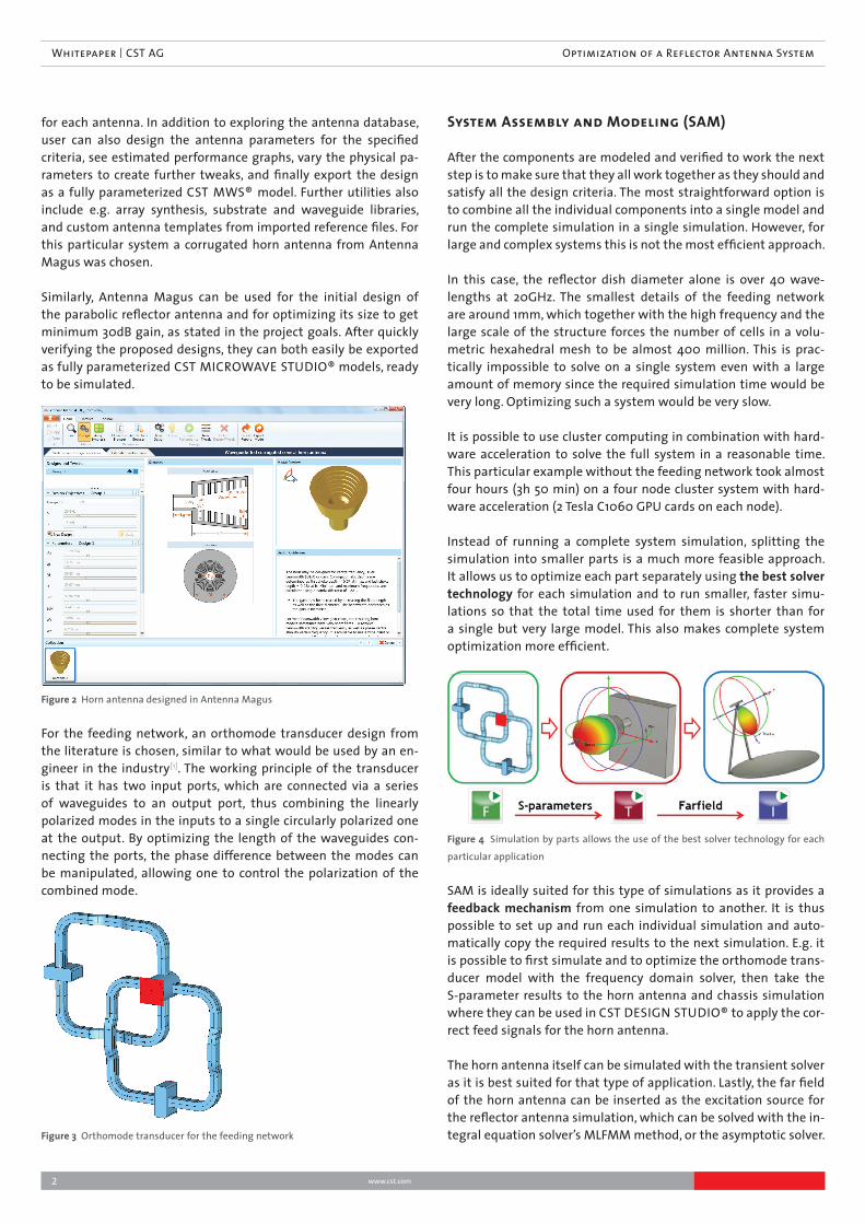
for each antenna. In addition to exploring the antenna database, user can also design the antenna parameters for the specified criteria, see estimated performance graphs, vary the physical pa-rameters to create further tweaks, and finally export the design as a fully parameterized CST MWS® model. Further utilities also include e.g. array synthesis, substrate and waveguide libraries, and custom antenna templates from imported reference files. For this particular system a corrugated horn antenna from Antenna Magus was chosen.
Similarly, Antenna Magus can be used for the initial design of the parabolic reflector antenna and for optimizing its size to get minimum 30dB gain, as stated in the project goals. After quickly verifying the proposed designs, they can both easily be exported as fully parameterized CST MICROWAVE STUDIO® models, ready to be simulated.
Figure 2 Horn antenna designed in Antenna Magus
For the feeding network, an orthomode transducer design from the literature is chosen, similar to what would be used by an en-gineer in the industry[1]. The working principle of the transducer is that it has two input ports, which are connected via a series of waveguides to an output port, thus combining the linearly polarized modes in the inputs to a single circularly polarized one at the output. By optimizing the length of the waveguides con-necting the ports, the phase difference between the modes can be manipulated, allowing one to control the polarization of the combined mode.
Figure 3 Orthomode transducer for the feeding network
System Assembly and Modeling (SAM)
After the components are modeled and verified to work the next step is to make sure that they all work together as they should and satisfy all the design criteria. The most straightforward option is to combine all the individual components into a single model and run the complete simulation in a single simulation. However, for large and complex systems this is not the most efficient approach.
In this case, the reflector dish diameter alone is over 40 wave-lengths at 20GHz. The smallest details of the feeding network are around 1mm, which together with the high frequency and the large scale of the structure forces the number of cells in a volu-metric hexahedral mesh to be almost 400 million. This is prac-tically impossible to solve on a single system even with a large amount of memory since the required simulation time would be very long. Optimizing such a system would be very slow.
It is possible to use cluster computing in combination with hard-ware acceleration to solve the full system in a reasonable time. This particular example without the feeding network took almost four hours (3h 50 min) on a four node cluster system with hard-ware acceleration (2 Tesla C1060 GPU cards on each node).
Instead of running a complete system simulation, splitting the simulation into smaller parts is a much more feasible approach. It allows us to optimize each part separately using the best solver technology for each simulation and to run smaller, faster simu-lations so that the total time used for them is shorter than for a single but very large model. This also makes complete system optimization more efficient.
Figure 4 Simulation by parts allows the use of the best solver technology for each
particular application
SAM is ideally suited for this type of simulations as it provides a feedback mechanism from one simulation to another. It is thus possible to set up and run each individual simulation and auto-matically copy the required results to the next simulation. E.g. it is possible to first simulate and to optimize the orthomode trans-ducer model with the frequency domain solver, then take the S-parameter results to the horn antenna and chassis simulation where they can be used in CST DESIGN STUDIO® to apply the cor-rect feed signals for the horn antenna.
The horn antenna itself can be simulated with the transient solver as it is best suited for that type of application. Lastly, the far field of the horn antenna can be inserted as the excitation source for the reflector antenna simulation, which can be solved with the in-tegral equation solver’s MLFMM method, or the asymptotic solver.

Whitepaper | CST AG Optimization of a Reflector Antenna System
3www.cst.com
The total simulation time for the horn (using the already optimized feed system S-parameters) and the reflector antenna simulations together is approximately 25 minutes, compared to the nearly four hours with the complete model with the transient solver.
SAM can also help with project and file management. Instead of keeping track of individual model files and simulations and all possible configurations that usually accumulate during a design and optimization process, all the components can be imported into a single master file. Engineers can then work with them directly within this master file, to combine them to create new simulations, to analyze the results, and to simultaneously opti-mize multiple components.
Figure 5 Comparison of the complete system simulation and the simulation by
parts approach
Simulation Setup with SAM
The first step in setting up the SAM simulation is to import all the individual component designs into a new CST DESIGN STUDIO project. The required components must be first designed sepa-rately as parameterized models. Any changes that are made in the original model files can be updated to the System Assembly Model. It is thus possible to modify the imported models even af-ter the import, as the system looks up the updated information from the original files.
The next step is to build a schematic representation of the im-ported models to define the electrical connections between the ports of the components, in other words, a circuit representation of the model. The schematic representation can be used directly for circuit simulations or for automatic alignment of the compo-nents in the 3D layout. The layout view of the system is a three dimensional view where the components can be positioned in the correct locations. The snapping tool can use the schematic port connection information to semi-automatically align the compo-nents with minimal user input.
Based on the schematic and the three dimensional layout it is possible to generate new simulation projects with any combi-nation of the imported models. A simulation project is simply a
CST STUDIO SUITE model that is stored locally within the mas-ter file. The user thus does not need to keep track of multiple file versions or component combinations, as the data as well as the simulation results are stored in a single file. All parameter changes in the master model are automatically updated across all the generated simulation projects.
Figure 6 Schematic presentation of the individual components used in system
assembly model
Figure 7 Port connection information from the schematic (shown as green lines)
can be used to semi-automatically align 3D components in the correct locations
For the reflector antenna system one could thus first build a mod-el for the feeding network, then simulate and optimize it using frequency domain solver. The feeding network results can be used in circuit form and applied to the horn antenna and the chassis simulation, which is solved e.g. with the transient solver. Lastly, the far field results of the horn antenna can be automatically im-ported as a source for the reflector dish simulation using either the integral equation or the asymptotic solver.
Since it is possible to run all simulation projects from a single place where the results can also be directly accessed, it is also pos-sible to automate the complete system optimization using the in-dividual simulation projects. The optimization could for example consist of the following steps:
4
Whitepaper | CST AG Optimization of a Reflector Antenna System
www.cst.com
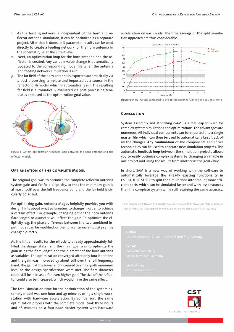
1. As the feeding network is independent of the horn and re-flector antenna simulation, it can be optimized as a separate project. After that is done, its S-parameter results can be used directly to create a feeding network for the horn antenna in the schematic, i.e. at the circuit level.
2. Next, an optimization loop for the horn antenna and the re-flector is created. Any variable value change is automatically updated to the corresponding model file when the antenna and feeding network simulation is run.
3. The far field of the horn antenna is exported automatically via a post-processing template and imported as a source in the reflector dish model, which is automatically run. The resulting far field is automatically evaluated via post processing tem-plates and used as the optimization goal value.
Figure 8 System optimization feedback loop between the horn antenna and the
reflector models
Optimization of the Complete Model
The original goal was to optimize the complete reflector antenna system gain and far field ellipticity, so that the minimum gain is at least 30dB over the full frequency band and the far field is cir-cularly polarized.
For optimizing gain, Antenna Magus helpfully provides you with design hints about what parameters to change in order to achieve a certain effect. For example, changing either the horn antenna flare length or diameter will affect the gain. To optimize the el-lipticity, e.g. the phase difference between the two combined in-put modes can be modified, or the horn antenna ellipticity can be changed directly.
As the initial results for the ellipticity already approximately ful-filled the design statement, the main goal was to optimize the gain using the flare length and the diameter of the horn antenna as variables. The optimization converged after only four iterations and the gain was improved by about 2dB over the full frequency band. The gain at the lower end increased over the 30db minimum level so the design specifications were met. The flare diameter could still be increased for even higher gain. The size of the reflec-tor could also be increased, which would have the same effect.
The total simulation time for the optimization of the system as-sembly model was one hour and 49 minutes using a single work-station with hardware acceleration. By comparison, the same optimization process with the complete model took three hours and 48 minutes on a four-node cluster system with hardware
acceleration on each node. The time savings of the split simula-tion approach are thus considerable.
Figure 9 Initial results compared to the optimized ones fulfilling the design criteria
Conclusion
System Assembly and Modelling (SAM) is a real leap forward for complex system simulations and optimizations. The advantages are numerous. All individual components can be imported into a single master file, which can then be used to automatically keep track of all the changes. Any combination of the components and solver technologies can be used to generate new simulation projects. The automatic feedback loop between the simulation projects allows you to easily optimize complex systems by changing a variable in one project and using the results from another as the goal value.
In short, SAM is a new way of working with the software to automatically leverage the already existing functionality in CST STUDIO SUITE to split the simulations into smaller, more effi-cient parts, which can be simulated faster and with less resources than the complete system while still retaining the same accuracy.
AuthorIlari Hanninen, CST AG – Support and Engineering
CST AGBad Nauheimer Str. 1964289 Darmstadt, Germany
[email protected]://www.cst.com
CHANGING THE STANDARDS
[1] G. Engargiola and A. Navarrini, “K-Band Orthomode Transducer With Waveguide Port and Balanced
Coaxial Probes,” IEEE Transactions on Microwave Theory and Techniques, vol. 53, May 2005.