01_PV Water Pumping System Using a Current-Fed Parallel Resonant Push-Pull Inverter for Rural Are

Solar Energy 139 (2016) 199–212
Contents lists available at ScienceDirect
Solar Energy
journal homepage: www.elsevier .com/locate /solener
Optimization of a PV fed water pumping system without storage basedon teaching-learning-based optimization algorithm and artificial neuralnetwork
http://dx.doi.org/10.1016/j.solener.2016.09.0220038-092X/� 2016 Elsevier Ltd. All rights reserved.
⇑ Corresponding author.E-mail addresses: [email protected] (M.M. Elkholy), [email protected]
(A. Fathy).
Mahmoud M. Elkholy, Ahmed Fathy ⇑Electrical Power and Machines Department, Faculty of Engineering, Zagazig University, Zagazig, Egypt
a r t i c l e i n f o
Article history:Received 24 June 2015Received in revised form 17 August 2016Accepted 19 September 2016Available online 5 October 2016
Keywords:Photovoltaic panelWater pumping systemTLBOANN
a b s t r a c t
In this paper an optimal performance of three phase induction motor drives a centrifugal water pump andfed from photovoltaic (PV) system without storage elements during starting and running is presented. Athree level three phase inverter is used to convert the DC voltage from the PV array to a variable voltageand frequency to supply the three phase induction motor. The output voltage and frequency of the inver-ter are controlled to extract the maximum power from solar panel during running at different levels ofirradiance and temperatures using a Teaching Learning Based Optimization (TLBO) algorithm with min-imum motor losses. The ratio of voltage magnitude and frequency is held within rated values to avoidsaturation and motor overheating. The rating of PV array is chosen to develop the rated power of thepump at normal irradiance and temperature. The output voltage of the inverter is controlled during start-ing to prevent an excessive current from PV and to develop a torque larger than pump torque. An artificialneural network (ANN) is developed to give an optimal inverter voltage and frequency to extract maxi-mum power from the PV array. The complete model is simulated using MATLAB/Simulink. The simulatedresults emphasize the significance of the proposed method to attain the maximum power from PV withminimum motor losses.
� 2016 Elsevier Ltd. All rights reserved.
1. Introduction
Due to increase in demands for energy around the world andthe expected end of fossil fuel; renewable energy sources gaineda great attention as alternatives. PV is one of the most importantclean energy sources. A PV system composes PV cell which pro-duces a direct current in case of falling solar radiation on its sur-face. The PV can be used for water-pumping application inremote areas (Masters, 2004), it raises water from a well or springand stores in a tank for irrigation purpose. The PV-water pump sys-tem operation differs from that of the AC Mains powered pump, asthey work under varying input power conditions.
Many previous studies in the point of optimal operation of thePV-water pump system have been presented and literature asfollows.
An optimal strategy for operating the PV pumping system com-poses an induction motor driving a centrifugal pump has beenintroduced in Betka and Attali (2010) and Betka and Moussi
(2004); it has been achieved by maximizing the motor efficiencyand minimizing the machine losses. A hybrid GA-ANN algorithmhas been introduced in Kulaksız and Akkaya (2012) for minimizingthe converter losses inserted in a PV system coupled with aninduction motor. The matching of an induction motor drivenwater-pumping system to PV array in order to transfer maximumenergy has been given in Akbaba (2007); a double step-up con-verter and six-step voltage source inverter have been embeddedin this work. In Benlarbi et al. (2004), a fuzzy optimizationapproach to improve the global efficiency of a PV water pumpingsystem and maximize the speed of drive then increasing waterdischarge rate has been presented. The optimal performance ofthe PV-water pump system driven by DC motor at different pat-terns of solar radiation and ambient temperature has been ana-lyzed in Ghoneim (2006) and Jaziri and Jemli (2013). Anoptimization approach based on the detection of the optimalpower flow between the PV system and water pump throughthe usage of maximum power point tracker has been given inBadoud et al. (2013). Takagi-Sugeno fuzzy approach has beendeveloped in Ouachani et al. (2013) to extract the maximumpower from the PV system feeding a water pump via DC motor.The usage of DC and induction motor as a part of multi and single

Fig. 1. PV cell equivalent circuit.
Nomenclature
Iph photon currentIo saturation current of the diodeV cell voltageI cell currentRs cell series resistanceRp cell parallel resistancea ideality factor of the diodeVT thermal voltages of the diodeNss number of series modulesNpp number of parallel stringsRsarr PV array series resistanceRparr PV array parallel resistanceVLLrms the fundamental line voltage of the inverterm the modulation indexVds d-axis stator voltageVqs q-axis stator voltageids d-axis stator currentIqs q-axis stator currentRst stator winding resistancekds d-axis stator flux linkage
kqs q-axis stator flux linkagexs synchronous speedidR d-axis referred rotor currentIqR q-axis referred rotor currentRR referred rotor winding resistancekdR d-axis rotor flux linkagekqR q-axis rotor flux linkagex rotor speedLs self-inductance of stator windingLR referred self-inductance of rotor windingM mutual inductanceTe electromagnetic torqueJ moment of inertialB friction coefficientTL load torqueTLBO teaching learning based optimizationANN artificial neural networkPV photovoltaic
200 M.M. Elkholy, A. Fathy / Solar Energy 139 (2016) 199–212
stage water pump system has been reviewed in Periasamy et al.(2015); additionally the various techniques of MPPT have beenintroduced. A single stage water pumping system comprises PVarray, six-step square wave inverter, induction motor and cen-trifugal pump has been presented in Muljadi (1997). The maxi-mum power of the PV array has been obtained by operating theinverter as variable frequency; additionally the losses due toswitching process have been minimized. An optimal design algo-rithm based on photovoltaic opportunity irrigation (POI) appliedon several sub-models represented PV generator, variable speedcentrifugal pump and olive orchard has been implemented inLuque et al. (2015). An optimized stand-alone solar pumping sys-tem has been implemented in Corrêa and Silva (2012); the objec-tive of this algorithm is to maximize the PV array efficiency usingmaximum power point tracking algorithm and minimize theinduction motor losses. A linear actuated water pump driven bysolar system has been optimized in Wade and Short (2012) to suitthe PV power characteristic and hydraulic requirements. An opti-mization process for maximizing the quantity of water pumpedfrom the water pump system driven from an induction motor withimproving the induction motor efficiency by obtaining an opti-mum voltage-frequency relation to control the motor has beenintroduced in Betka and Moussi (2005); additionally the impactof changing the PV array temperature has been studied. The per-formance of induction motor-pump system for irrigation purposesupplied from PV system has been studied in Gumus and Yakut(2015) and Belgacem (2012).
In this paper a Teaching Learning Based Optimization (TLBO)algorithm is used to have the optimal values of inverter voltageand frequency to obtain a maximum power from PV and to mini-mize the losses of three phase induction motor drives a centrifugalwater pump. ANN is built up to have PV maximum power point atany solar radiation and temperature. This maximum PV power isused as an input signal for other ANN to give optimal inverter volt-age and frequency after trained by data obtained from TLBO algo-rithm. The field weakening method of reduced voltage andconstant frequency is used to start the induction motor to avoidhigh starting current from PV. The complete system of PV array,three level inverter, three phase induction motor and centrifugalpump is simulated by MATLAB/Simulink.
2. Mathematical model
The system under study consists of photovoltaic array thatcomposed of a number of modules of type First Solar FS-64 272,formed by the interconnection of 8 series connected modules perstring and 3-parallel strings, 3-level 65 three phase inverter,1.1 kW three phase induction motor and water pump load. Themathematical model of each part is given in this section.
2.1. PV array model
The PV cell is simulated by a parallel current source representsthe photon current connected in parallel with a diode and resis-tance, all in series with series resistance as shown in Fig. 1.
The PV cell output current is given as follows (El-arini et al.,2013; Fathy et al., 2013):
I ¼ Iph � ID � Ip ð1Þ
I ¼ Iph � Io expV þ IRs
aVT
� �� 1
� �� V þ IRs
Rp
� �ð2Þ
where Iph is the photon current which is generated by the sunlightstrikes the PV cell surface, Io is the saturation current of the diode, Vand I are the cell voltage and current respectively, Rs and Rp are thecell series and parallel resistances respectively, a is the ideality fac-tors of the diode and VT is the thermal voltages of the diode. The PVarray is formulated by connecting Nss PV modules in series and Npp

Fig. 2. The arrangement of a PV array (Fathy, 2015).
Table 1Switching states for one phase of three level inverter.
Output Voltage S1 S2 S3 S4
0.5Vdc 1 1 0 00 0 1 1 0�0.5Vdc 0 0 1 1
M.M. Elkholy, A. Fathy / Solar Energy 139 (2016) 199–212 201
parallel strings as shown in Fig. 2, the current supplied from the PVarray is written by:
Iarr ¼ NppIph � NppIo expV þ IRsarr
aNssVT
� �� 1
� �� V þ IRsarr
Rparr
� �ð3Þ
where Rsarr and Rparr are the series and parallel resistances of the PVarray and given by Fathy (2015):
Rsarr ¼ Nss
Npp
� �NsRs and Rparr ¼ Nss
Npp
� �NsRp ð4Þ
2.2. Three level three phase inverter model
The three-level inverter consists of three arms of power switch-ing devices. Each arm consists of four switching devices along withtheir antiparallel diodes and two neutral clamping diodes as shownin Fig. 3 (Rajesh and Manjesh, 2014). The switching states of onephase three level inverter are listed in Table 1.
The rms value of the fundamental line voltage of the inverter isgiven as:
VLLrms ¼ m
ffiffiffi3
pffiffiffi2
p 0:5Vdc ¼ 0:6124mVdc ð5Þ
Fig. 3. Three level inve
where m is the modulation index which controls the amplitude ofthe fundamental component of the output voltage of the inverter.The modulation index must be greater than 0 and lower than orequal to 1.
There are advantages in the application of the three level neu-tral point clamped inverters fed three phase induction motor overconventional two level inverters as three level inverter can reduceharmonics in the output voltage and current due to the multileveloutput voltage (Adrian and Kokkosis, 2011).
2.3. Three phase induction motor model
The mathematical model of squirrel cage three phase inductionmotor in the d-q frame is given as (Chiasson, 2005).
The voltage equations of three phase squirrel cage inductionmotor in d-q frame are listed as follows.
The stator voltage equations are:
VdS ¼ idSRst þ ddt
kdS �xSkqS ð6Þ
VqS ¼ iqSRst þ ddt
kqS þxSkdS ð7Þ
where VdS is d-axis stator voltage, VqS is q-axis stator voltage, idS isd-axis stator current, iqS is q-axis stator current, Rst is stator windingresistance, kdS is d-axis stator flux linkage, kqS is q-axis stator fluxlinkage and xS synchronous speed in rad/s.
The rotor voltage equations are:
0 ¼ idRRR þ ddt
kdR � ðxS �xÞkqR ð8Þ
rter construction.

C 2
C 1
S 1c
S 2c
a
bc
abc
AC MotorS 3c
S 4c
S 1b
S 2b
S 3b
S 4 b
S 1a
S 2a
S 3a
S 4a
Water Pump
PV
ANN( MPPT)
T
G
PVmax ANN(Trained by
TLBO results)
f
V3 level PWM
Generator
(a)
(b)
Fig. 4. (a) The physical configuration of the proposed system and (b) the Simulink model of the system.
Table 2The key specifications of the Solar FS-272 PV module.
Parameter Value
Open circuit voltage (Voc) 94.5738 VVoltage at maximum power point (Vmp) 70.558 VShort circuit current (Isc) 1.181 ACurrent at maximum power point (Imp) 1.0109 AMaximum power at STC (Pmax) 71.3271 WNumber of cells connected in series 116Temperature coefficient of Isc 0.0005433 A/�CTemperature coefficient of Voc �0.269 V/�C
202 M.M. Elkholy, A. Fathy / Solar Energy 139 (2016) 199–212
0 ¼ iqRRR þ ddt
kqR þ ðxS �xÞkqRkdR ð9Þ
where idR is d-axis referred rotor current, iqR is q-axis referred rotorcurrent, RR is referred rotor winding resistance, kdR is d-axis rotorflux linkage, kqR is q-axis rotor flux linkage and x is the rotor speedin rad/s.
The flux linkages are defined by:
kdS ¼ LSidS þMidR ð10Þ
kqS ¼ LSiqS þMiqR ð11Þ

Fig. 5. (a) I-V and P-V characteristics of one PV module and (b) I-V and P-V characteristics of total array.
0 100 200 300 400 500 600 700 800 900 100010
-1
100
101
102
103
104
105
106 Best Training Performance is 0.17573 at epoch 1000
Mea
n Sq
uare
d Er
ror
(mse
)
1000 Epochs
TrainBest
Fig. 6. Variation of PV MPP ANN mean square error with epochs.
0 300 600 900 1200 15000
5
10
15
20
Speed (rpm)
Tor
que
(N.m
)
PumpTorque
10 Hz44 V/ph
20 Hz88 V/ph
30 Hz132 V/ph
40 Hz176 V/ph
50Hz220 V/ph
Fig. 7. Variation of motor developed torque and pump torque with speed.
Table 3Parameters of the IM.
Parameter Value
Stator resistance 7.4826 ΩStator leakage inductance 0.0221 HReferred rotor resistance 3.6840 ΩReferred rotor leakage inductance 0.0221 HMagnetizing reactance 0.4114 HCore loss resistance 2400 ΩMoment of Inertia 0.02 kg m2
M.M. Elkholy, A. Fathy / Solar Energy 139 (2016) 199–212 203
kdR ¼ LRidR þMidS ð12Þ
kqR ¼ LRiqR þMiqS ð13Þwhere LS is self-inductance of stator winding, LR is referred self-inductance of rotor winding, M is mutual inductance.
The electromagnetic torque equation is:
Te ¼ 32p2M iqSidR � idSiqR� � ð14Þ

0 300 600 900 1200 15000
2
4
6
8
10
12
14
Speed (rpm)
Stat
or C
urre
nt (A
)10 Hz44 V/ph
20 Hz88 V/ph
30 Hz132 V/ph
40 Hz176 V/ph
50Hz220 V/ph
Fig. 8. Variation of motor current torque with speed.
Table 4Optimum starting slope on inverter voltage.
Maximum PV power Slope
340.6 8784.1 251245 281400 31
0 300 600 900 1200 15000
1000
2000
3000
4000
5000
6000
Speed (rpm)
Inpu
t Pow
er (W
)
40 Hz176 V/ph
30 Hz132 V/ph
20 Hz88 V/ph
10 Hz44 V/ph
50Hz220 V/ph
Fig. 9. Variation of motor input power with speed.
204 M.M. Elkholy, A. Fathy / Solar Energy 139 (2016) 199–212
The mechanical equation of the motor and the load is:
Te � TL ¼ Jdxdt
þ Bx ð15Þ
where J is moment of inertial in kg m2, and B friction N.m.s.The practical characteristic of 1.1 kW, 1440 rpm (150.8 rad/s)
centrifugal pump can be given as (ETAP11):
TL ¼ 0:7634� 0:0461xþ 0:0011x2 þ 0:000003273x3 ð16Þwhere x is pump speed in rad/s.
3. Characteristics of the proposed system
The proposed water pump system consists of a photovoltaicarray which acts as a power supply source, connected to a pulsewidth modulation (PWM) 3-level three phase inverter, which con-verts the DC voltage to variable voltage variable frequency AC volt-age in order to supply a three-phase induction motor. The physicalconfiguration of the proposed system and the complete systemdescription are shown in Fig. 4(a) and (b) respectively. In theproposed system; the PV array maximum power is extracted viaa neural network approach at different solar radiation and
temperature. The TLBO algorithm is used to have an optimal inver-ter frequency and voltage to forward this PV maximum power towater pump with minimum motor losses. Other ANN is trainedby TLBO results to have an adaptive controller gives optimal inver-ter frequency and voltage.
3.1. PV array model characteristics
A photovoltaic array consists of a number of modules of typeFirst Solar FS-272, formed by the interconnection of 8 series con-nected modules per string and 3 parallel strings, connected to pro-vide the required voltage and current. The key specification of thePV module under study is given in Table 2 and the unknownparameter determination method is given in Ma et al. (2014).
The characteristics of one module and the used array at 25 �Care shown in Fig. 5(a) and (b) respectively.
3.2. Neural network MPPT design
A neural network is designed to give the maximum PV power atcertain solar radiation and ambient temperature. The ANN has twoinput layers of solar radiation and temperature and one outputlayer of maximum PV power. Practical data of solar radiation andambient temperature measured by solar radiation and meteorolog-ical station located at National Research Institute of Astronomyand Geophysics Helwan, Cairo, Egypt are used to extract the PVmaximum power which is a target of ANN model. The variationof mean square error of the network with epochs is shown in Fig. 6.
3.3. Water pump induction motor characteristics
In water pump induction motor system; the output power ofthe pump can be controlled by the variation of the motor voltageand frequency. The parameters of 4-pole, 220/380 V, 1.1 kW,50 Hz three phase induction motor used to drive the water pumpare listed as given in Table 3 (Elbarbary and Elkholy, 2013).
The performance characteristics of the motor with V/f controlmethod are given to determine the required motor input powerto drive the water pump at different speeds. Fig. 7 shows the vari-ation of motor developed torque and water pump torque withspeed at which V/f control method is used. The operating speedsare the intersections of both motor and pump torques. Fig. 8 showsthe variation of motor current with speed at different frequencies.It’s shown that the starting current is higher than normal operatingcurrent and this starting current is higher than the short circuitcurrent of the PV panel. Therefore stator voltage should be con-trolled during starting to limit the starting current provided that

Define the popula�on size, number of itera�ons and constraintsIden�fy the independent variables (frequency, voltage and slip)
calculate the mean of each variableCalculate OF as defined in Eq. (22)
Update the solu�on using Eq. (19)
fit(xnewi) < fit(xold
i)Reject xnewi
No
Select two random solu�on xi and xj
Yes
fit(xi) < fit(xj)
Update solu�on using Eq.(20) Update solu�on using Eq. (21)
Yes No
fit(xnewi) < fit(xold
i)
Are constraints sa�sfied
Yes
Op�mal solu�on is obtained
End
Start
Yes
No
Fig. 10. The main steps of TLBO algorithm.
200 400 600 800 1000 1200 1400 160025
30
35
40
45
50
PV maximum power (W)
Inve
rter
freq
uenc
y (H
z)
Fig. 11. Variation of optimal inverter frequency with PV maximum power.
M.M. Elkholy, A. Fathy / Solar Energy 139 (2016) 199–212 205
the motor torque is higher than the pump torque and starting cur-rent is lower than short circuit current of PV array. The optimalslope of increasing voltage at different levels of solar radiationand temperature are obtained using TLBO algorithm as shown inTable 4. The variation of motor input power with speed is shownin Fig. 9. The input power at lower frequencies is lower than oneof rated frequency. Therefore, at different PV maximum powerwith different temperatures and irradiances, the inverter voltage
and frequency are controlled to match drive power with PV maxi-mum power.
4. Teaching learning based optimization algorithm (TLBO)
TLBO is a new meta-heuristic optimization algorithm that hasbeen developed by Rao et al. (2011). It has been advisable to use

200 400 600 800 1000 1200 1400 160080
100
120
140
160
180
200
220
PV maximum power (W)
Inve
rter
out
put v
olta
ge (V
/ph)
Fig. 12. Variation of optimal inverter output voltage with PV maximum power.
0 50 100 150 200 250200220240260280300320340360380400420440460480500
Iterations
TLB
O O
bjec
tive
Fun
ctio
n
Fig. 13. Variation of the TLBO objective function with iterations.
Table 5TLBO and PSO results.
PV maxpower (W)
TLBO method PSO method
Inverterfrequency Hz
Slip Invertervoltage (V)
Motor speed(rpm)
Motor loss(W)
Inverterfrequency (Hz)
Slip Invertervoltage (V)
Motor speed(rpm)
Motor loss(W)
100 20.1073 0.0594 46.3591 567.39 29.3993 20.1543 0.0616 45.7341 567.38 29.4138150 22.6665 0.0534 60.0158 643.68 40.9957 22.6702 0.0534 59.9941 643.79 40.9918200 24.7387 0.0495 72.0672 705.42 51.8439 24.766 0.0504 71.5738 705.53 51.8198250 26.5183 0.047 82.8163 758.16 62.1315 26.5079 0.0461 83.4974 758.58 62.1209300 28.1348 0.0453 92.629 805.81 72.002 28.1184 0.0447 93.1298 805.85 71.9916350 29.5342 0.0423 103.3462 848.55 81.591 29.5258 0.0417 103.846 848.84 81.5974400 30.9487 0.043 110.1474 888.54 90.8793 30.9215 0.0421 111.1023 888.59 90.8438450 32.1477 0.0401 120.6153 925.76 99.9339 32.1011 0.0388 122.2139 925.67 100.0098500 33.3355 0.0396 128.2124 960.46 108.8459 33.339 0.0393 128.5509 960.86 108.7894550 34.4459 0.0378 137.4311 994.32 117.5596 34.4505 0.038 137.0371 994.24 117.5081600 35.5396 0.0377 144.0142 1025.99 126.0958 35.4775 0.036 146.7463 1026.01 126.1963650 36.623 0.038 149.7619 1056.94 134.5377 36.5967 0.0374 150.5817 1056.84 134.4752700 37.5719 0.0362 158.709 1086.35 142.8025 37.5699 0.036 159.1732 1086.52 142.7744750 38.6102 0.0371 163.058 1115.33 151.0505 38.5887 0.0366 163.9129 1115.29 150.9724800 39.5359 0.0363 170.0963 1143.02 159.1024 39.4976 0.0351 172.4242 1143.34 159.0316850 40.484 0.0362 175.9417 1170.55 167.2486 40.5629 0.0384 171.5544 1170.16 167.7269900 41.3623 0.0361 181.4707 1196.07 175.1899 41.4129 0.0364 180.6955 1197.16 175.1873950 42.3225 0.0366 185.519 1223.20 183.2657 42.3497 0.0374 183.8711 1222.97 183.51451000 43.2101 0.037 189.9317 1248.34 191.4886 43.2197 0.0371 189.5834 1248.49 191.35031050 44.0822 0.0379 192.8445 1272.34 200.0054 44.1088 0.0375 193.5545 1273.64 199.50511100 44.9254 0.038 197.2716 1296.55 207.9656 44.8052 0.038 197.1429 1293.08 208.09491150 45.8562 0.0386 200.6755 1322.58 216.3114 45.8363 0.0385 200.8981 1322.15 216.04531200 46.6963 0.0384 205.4635 1347.09 223.9036 46.5198 0.037 208.9696 1343.96 223.07641250 47.5258 0.039 208.7387 1370.17 232.4754 47.5475 0.039 208.679 1370.79 232.32581300 48.3488 0.0398 211.2128 1392.74 241.2323 48.4005 0.03984 211.1043 1394.17 241.20411350 49.1907 0.0394 216.3782 1417.58 248.7144 49.2123 0.0393 216.5343 1418.35 248.43881400 50.0487 0.0396 220 1442.00 256.744 50.0458 0.03998 219.136 1441.35 257.2185
206 M.M. Elkholy, A. Fathy / Solar Energy 139 (2016) 199–212

0 100 200 300 400 500 600 700 800 900 1000
10-2
100
102
104
Best Training Performance is 0.0062238 at epoch 1000
Mea
n S
qu
ared
Err
or
(m
se)
1000 Epochs
TrainBest
Fig. 14. Variation of ANN mean square error with epochs.
200 400 600 800 1000 1200 1400-10
0
10
20
30
40
50
PV maximum power ( ANN input)
Sim
ulat
ed a
nd T
arge
t of A
NN
out
put
fr
eque
ncy
TargetSimulatederror
Fig. 15. Variation of ANN output frequency.
200 400 600 800 1000 1200 1400-50
0
50
100
150
200
250
PV maximum power ( ANN input)
Sim
ulat
ed a
nd T
arge
t of A
NN
out
put v
olta
ge
TargetSimulatederror
Fig. 16. Variation of ANN output voltage.
M.M. Elkholy, A. Fathy / Solar Energy 139 (2016) 199–212 207
TLBO in finding the global optimal solutions for continuous andnonlinear functions as it requires less computational time andgives high accurate results. The teaching process used in TLBOalgorithm is based on the interaction between the teacher in ateaching class with students which is known as teacher phaseand the interaction between two groups of students which isknown as learner phase; through these two phases of learningthe global optimal solution is obtained. A good teacher results ingood learners as teacher is considered as the best person thattransfers his knowledge to the learners. The main advantages of
TLBO algorithms have been mentioned in Pawar and Rao (2013);it needs less controlling parameters such as the size of population,number of generations and number of iterations, additionally it isreliable algorithm that guarantees the obtaining of optimal solu-tion not local one and easier than other meta-heuristic algorithms.
4.1. Teacher phase
In this stage of learningprocess; the students are learned throughthe teacher which is considered as the person who has the most

0 500 1000 150010
20
30
40
50
60
70
80
90
Motor Input Power (W)
Eff
icie
ncy
%V/f Control
Proposed TLBO Method
Fig. 17. Variation motor efficiency with input power with proposed and V/f methods.
0 5 10 15 20 25 30 35 40400
450
500
550
600
650
700
750
800
Time (s)
Sola
r R
adia
tion
(w/m
2)
Fig. 18. Variation of solar radiation with time.
0 5 10 15 20 25 30 35 4030
32
34
36
38
40
42
44
46
48
50
Time (s)
Inve
rter
Fre
quen
cy (H
z)
Fig. 19. Variation of Inverter frequency with time.
208 M.M. Elkholy, A. Fathy / Solar Energy 139 (2016) 199–212
experience and knowledge in a subject, therefore the teacher is con-sidered as the best (optimal) solution in the class room population.Practically the teacher moves the mean of his/her knowledge tothe class based on the capability of the class and cannot move his/her full knowledge.One candescribe thedifferencebetween the tea-cher result and mean result of learners as follows (Rao et al., 2011):
Diff Meani ¼ riðMnew � TFMiÞ ð17Þwhere Mnew is the new obtained mean of the teacher after movingits mean knowledge to learners, Mi is the mean of transferred
knowledge from teacher to students, ri is a random value in range[0, 1] and TF is the teaching factor which controls the mean valueto be changed. The value of TF can be either 1 or 2 based on the fol-lowing equation:
TF ¼ round½1þ randð0;1Þf2� 1g� ð18ÞBased on the difference between two means given in Eq. (17);
the value of solution is updated as follows:
xnewi ¼ xoldi þ Diff Meani ð19Þ

0 5 10 15 20 25 30 35 40
-600
-400
-200
0
200
400
600
Time (s)
Inve
rter
Out
put L
ine
Vol
tage
(V)
Fig. 20. Variation of Inverter output voltage with time.
0 5 10 15 20 25 30 35 401
1.5
2
2.5
Time (s)
PV A
rray
Cur
rent
(A)
Fig. 21. Variation of PV array current output voltage with time.
0 5 10 15 20 25 30 35 400
100
200
300
400
500
600
700
Time (s)
PV A
rray
Vol
tage
(V)
Fig. 22. Variation of PV array voltage output voltage with time.
M.M. Elkholy, A. Fathy / Solar Energy 139 (2016) 199–212 209
where xnewi is the updated solution, xoldi is the old solution. The newsolution is accepted if its fitness function is better than the previousone. The accepted solution acts as input to the second stage oflearning process which is learner phase.
4.2. Learner phase
In this stage of learning process; the knowledge is transferred toa group of students through the interaction with another group. In
order to explain the learner phase, it is assumed that there are twogroups of students group i and group j, with knowledge xi and xj, atthe beginning of this process the fitness function of both groups arecalculated and compared such that the knowledge has beenupdated based on the following formula:
xnewi ¼ xoldi þ riðxi � xjÞ if fitðxiÞ < fitðxjÞ ð20Þ
xnewi ¼ xoldi þ riðxj � xiÞ if fitðxjÞ < fitðxiÞ ð21Þ
0 5 10 15 20 25 30 35 400
200
400
600
800
1000
1200
1400
Time (s)
PV A
rray
Pow
er (W
)
Fig. 23. Variation of PV array power with time.
0 5 10 15 20 25 30 35 40-200
0
200
400
600
800
1000
1200
1400
Time (s)
Shaf
t Spe
ed (r
pm)
Fig. 24. Variation of pump speed with time.
0 5 10 15 20 25 30 35 400
1
2
3
4
5
6
7
8
9
10
Time (s)
Mot
or a
nd L
oad
Tor
que
(N.m
) Tmotor
TLoad
Fig. 25. Variation of motor and pump torque with time.
210 M.M. Elkholy, A. Fathy / Solar Energy 139 (2016) 199–212
where fit(xi) and fit(xj) are the fitness function of group i and jrespectively. The updated solution, xnewi , is accepted if its fitnessfunction is better than the previous one. The flow chart representsthe main steps of TLBO algorithm is given in Fig. 10.
5. Numerical analysis and results
The Teaching Learning Based Optimization method is used toobtain the optimal inverter voltage and frequency for certain max-imum PV power to drive the water pump with minimum motor
losses. The objective function is (OF) defined in Eq. (22) to mini-mize the motor losses with different constraints of Eq. (23).
OF ¼ Minimize½3� ðI2s Rst þ I2RRR þ I2c RcÞ� ð22Þwhere Is is the stator current, IR is the rotor current referred to sta-tor, Ic is the core loss current and Rc is the core loss resistance.
jinput power � PV maximum powerj < 1jmotor torque� pump torquej < 0:01
Vf 6
Vratedf rated
8><>: ð23Þ

Fig. 26. FFT for output voltage in case of 2 and 3 level inverter.
Fig. 27. FFT for motor current in case of 2 and 3 level inverter.
M.M. Elkholy, A. Fathy / Solar Energy 139 (2016) 199–212 211
The TLBO parameters used are population size = 50, maximumnumber of generations = 200, Variable numbers = 3. The designvariables are frequency, voltage and slip. For each maximumpower of solar panel the TLBO program is run for 20 times andthe best result is recorded as shown in Figs. 11 and 12.
The variation of TLBO objective function for maximum power of1300W is shown in Fig. 13 for 20 running times. The ranges ofTLBO variables frequency, voltages and slip respectively are lowerlimit = [45 180 0.0001] and upper limit = [50 220 0.4].
To validate the results of TLBO method, these results are com-pared with results of Particle Swarm Optimization (PSO) methodas given in Table 5. It’s shown that the two results are very closetogether. The parameters of PSO are: number of particles inswarm = 24 and maximum number of generations = 200.
To have a fast and adaptive controller, a feed-forward backpropagation ANN is designed to give the optimal inverter voltageand frequency. The input of ANN is PV maximum power and theoutputs of ANN are inverter voltage and frequency. The trainingdata of ANN are the optimal voltage and frequency at each PVmax-imum power which are obtained using TLBO algorithm. The varia-tion of mean square error is shown in Fig. 14.
After training of the ANN, the maximum PV power is given tothe trained ANN and the output of inverter voltage and frequencyare obtained. The variation of simulated result, target and the errorbetween them are shown in Figs. 15and 16.
The variation of motor efficiency with input power is shown inFig. 17. The efficiency of the proposed method which to becomethe inverter voltage and frequency to obtain the maximum power

Table 6FFT for 2 and 3 level inverter voltage and current .
Harmonicorder
3 Level inverter 2 Level inverter
Invertervoltage (%)
Invertercurrent (%)
Invertervoltage (%)
Invertercurrent (%)
1 100 100 100 1002 0.19 0.4 0.21 1.733 0.35 0.63 0.51 0.144 0.12 0.09 0.58 0.285 0.19 0.13 0.57 0.346 0.15 0.06 1.01 0.567 0.16 0.08 0.58 0.28 0.11 0.07 0.44 0.459 0.18 0.24 0.71 0.1710 0.18 0.07 0.83 0.17
THD (%) 41.13 4.11 87.07 9.09
212 M.M. Elkholy, A. Fathy / Solar Energy 139 (2016) 199–212
from PV and operate the induction motor with minimum losses ishigher than that of V/f method especially at light input powers. Themotor efficiencies of two methods are very close for input powerthat is greater than 600W.
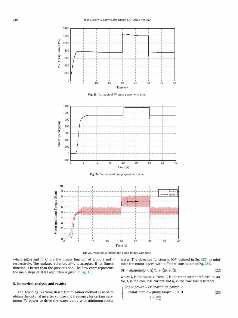
The performance characteristics of the system under solar radi-ation changes as 500 W/m2 from start up to 20 s, 750 W/m2 from20 s to 30 s and 500W/m2 from 30 s to 40 s is shown in Fig. 18with constant temperature at 25 �C. The variation of inverter fre-quency and voltage are shown in Figs. 19 and 20. During startingthe frequency is fixed at 39 Hz which is obtained from InverterANN and the inverter voltage is increased with slope 25 whichare obtained using TLBO algorithm when maximum PV is 784Wat G = 500W/m2 and T = 25 �C. The output current, voltage andpower of the PV array are shown in Figs. 21–23 respectively.Fig. 24 shows the variation of motor speed with time. It’s shownthat the motor speed is increased with solar radiation due toincreasing of the inverter frequency. The variation of motor andload pump torque with time is shown in Fig. 25.
To illustrate the effect of inverter type, a comparison betweenharmonic analysis for inverter voltage and current has been inves-tigated for 2 level and proposed one of 3 level as shown in Figs. 26and 27 respectively. It’s found that the 3 level inverter has lowerharmonic and lower Total Harmonic Distortion (THD) as summar-ized in Table 6.
6. Conclusion
In this paper an optimal performance of water pump inductionmotor connected directly to PV array via three level inverter with-out storage system is presented. The optimal performance isachieved by controlling the inverter voltage and frequency toobtain maximum power from PV with minimum motor lossesusing Teaching Learning Based Optimization technique. ANN isbuilt up to have PV maximum power point at any solar radiationand temperature. This maximum PV power is used as an input sig-nal for other ANN to give optimal inverter voltage and frequencyafter training by data obtained by TLBO method. The optimal slopeof increasing inverter output voltage with constant frequency dur-ing starting is obtained using TLBO algorithm. The whole system ofPV array, three level inverter, three phase induction motor andcentrifugal pump is modeled using MATLAB/Simulink and testedunder different radiations. After simulation the optimal invertervoltage and frequency to obtain PV maximum power with mini-
mum motor losses are obtained and ANN is built up to make thecontroller adaptive at different solar radiation and temperatures.
References
Adrian, S., Kokkosis, A., 2011. Vector control of induction machine fed by three levelinverter. J. Electr. Electron. Eng. 4 (1), 215–218.
Akbaba, M., 2007. Matching induction motors to PVG for maximum power transfer.Desalination 209, 31–38.
Badoud, A., Khemliche, M., Bouamama, B., Bacha, S., Villa, L., 2013. Bond graphmodeling and optimization of photovoltaic pumping system: simulation andexperimental results. Simul. Model. Pract. Theory 36, 84–103.
Belgacem, B., 2012. Performance of submersible PV water pumping systems inTunisia. Energy Sustain. Dev. 16, 415–420.
Benlarbi, K., Mokrani, L., Nait-Said, M., 2004. A fuzzy global efficiency optimizationof a photovoltaic water pumping system. Sol. Energy 77, 203–216.
Betka, A., Attali, A., 2010. Optimization of a photovoltaic pumping system based onthe optimal control theory. Sol. Energy 84, 1273–1283.
Betka, A., Moussi, A., 2004. Performance optimization of a photovoltaic inductionmotor pumping system. Renew. Energy 29, 2167–2181.
Betka, A., Moussi, A., 2005. Optimized solar water pumping system based on aninduction motor driving a centrifugal pump. Eur. Power Energy Syst.
Chiasson, J., 2005. Modelling and High Performance Control of Electric Machines.John Wiley & Sons Inc.
Corrêa Jr., T., Silva, S., 2012. Efficiency optimization in stand-alone photovoltaicpumping system. Renew. Energy 41, 220–226.
El-arini, M., Othman, A., Fathy, A., 2013. A new optimization approach formaximizing the photovoltaic panel power based on genetic algorithm andLagrange multiplier algorithm. Int. J. Photoenergy, 1–12.
Elbarbary, Z., Elkholy, M., 2013. Performance analysis of field orientation ofinduction motor drive under open gate of IGBT fault. Int. J. Power Electron.Drive Syst. (IJPEDS) 3 (3), 304–310.
ETAP11, Motor Load Model Library Model.Fathy, A., 2015. Reliable and efficient approach for mitigating the shading effect
on photovoltaic module based on modified artificial bee colony algorithm.Renew. Energy 81, 78–88.
Fathy, A., El-arini, M., Othman, A., 2013. A new evolutionary algorithm for theoptimal sizing of stand-alone photovoltaic system based on genetic algorithm.Int. Rev. Electr. Eng. 8 (3), 1067–1075.
Ghoneim, A., 2006. Design optimization of photovoltaic powered water pumpingsystems. Energy Convers. Manage. 47, 1449–1463.
Gumus, B., Yakut, Y., 2015. Analysis of induction motor-pump system supplied by aphotovoltaic generator for agricultural irrigation in southeastern Anatolianregion of Turkey. J. Electr. Eng. Technol. 10, 742–750.
Jaziri, S., Jemli, K., May 2013. Optimization of a photovoltaic powered waterpumping system. International Conference on Control, Decision andInformation Technologies, 6–8 May 2013, 422–428.
Kulaksız, A., Akkaya, R., 2012. A genetic algorithm optimized ANN-based MPPTalgorithm for a stand-alone PV system with induction motor drive. Sol. Energy86, 2366–2375.
Luque, R., Reca, J., Martinez, J., 2015. Optimal design of a standalone direct pumpingphotovoltaic system for deficit irrigation of olive orchards. Appl. Energy 149,13–23.
Ma, T., Yang, H., Lu, L., 2014. Development of a model to simulate the performancecharacteristics of crystalline silicon photovoltaic modules/strings/arrays. Sol.Energy 100, 31–41.
Masters, G.M., 2004. Renewable and Efficient Electric Power Systems. John Wiley &Sons Inc, Hoboken, New Jersey.
Muljadi, E., 1997. PV water pumping with a peak-power tracker using a simple six-step square-save inverter. IEEE Trans. Ind. Appl. 33 (3), 714–721.
Ouachani, I., Rabhi, A., Tidhaf, B., Zouggar, S., Elhajjaji, A., 2013. Optimization andcontrol for a photovoltaic pumping system. International Conference onRenewable Energy Research and Applications, 20–23 October 2013, Madrid,Spain, 734–739.
Pawar, P., Rao, R., 2013. Parameter optimization of machining processes usingteaching–learning-based optimization algorithm. Int. J. Adv. Manuf. Technol. 67(5), 995–1006.
Periasamy, P., Jain, N., Singh, I., 2015. A review on development of photovoltaicwater pumping system. Renew. Sustain. Energy Rev. 43, 918–925.
Rajesh, B., Manjesh, 2014. Analysis of THD and Harmonics in 3 Level Inverter withLC filter. ITSI Trans. Electr. Electron. Eng. 2 (4), 30–34.
Rao, R., Savsani, V., Vakharia, D., 2011. Teaching–learning-based optimization: anovel method for constrained mechanical design optimization problems.Comput. Aided Des. 43, 303–315.
Wade, N., Short, T., 2012. Optimization of a linear actuator for use in a solarpowered water pump. Sol. Energy 86, 867–876.