OPTIMISED DESIGN METHODOLOGIES FOR ENERGY-EFFICIENT...
72
This project has received funding from the European Union Seventh Framework Programme under grant agreement n° 609349. OPTIMISED DESIGN METHODOLOGIES FOR ENERGY-EFFICIENT BUILDINGS INTEGRATED IN THE NEIGHBOURHOOD ENERGY SYSTEMS eeEmbedded D4.2 ESIM Multi Model Responsible Authors: Jens Kaiser, Pit Stenzel, Co-Authors: Francisco Forns-Samso, Raphael Schär, Kenneth Solvik, Due date: 30.06.2015 Issue date: 03.09.2015 Nature: Other Coordinator: R. J. Scherer, Institute for Construction Informatics, Technische Universität Dresden, Germany
Transcript of OPTIMISED DESIGN METHODOLOGIES FOR ENERGY-EFFICIENT...

This project has received funding from the European Union Seventh Framework Programme
under grant agreement n° 609349.
OPTIMISED DESIGN METHODOLOGIES FOR ENERGY-EFFICIENT
BUILDINGS INTEGRATED IN THE NEIGHBOURHOOD ENERGY SYSTEMS
eeEmbedded
D4.2 ESIM Multi Model
Responsible Authors:
Jens Kaiser, Pit Stenzel,
Co-Authors:
Francisco Forns-Samso, Raphael Schär, Kenneth Solvik,
Due date: 30.06.2015
Issue date: 03.09.2015
Nature: Other
Coordinator: R. J. Scherer, Institute for Construction Informatics, Technische Universität Dresden, Germany
D4.2 - ESIM Multi Model
Version 1.0
Page 2/72
© eeEmbedded Consortium www.eeEmbedded.eu
Start date of project: 01.10.2013 Duration: 48 months
Organization name of lead contractor for this deliverable: IET
History
Version Description Lead Author Date
0.1 Deliverable Structure IET 05.01.2015
0.2 Figures in several chapters EAS, IET, SAR 15.06.2015
0.3 Enhancements of the text; additional pictures EAS, IET, SAR 05.08.2015
0.4 Re-arrangement of the chapters EAS, IET, SAR 17.08.2015
0.5 Enhancements of the text; additional pictures EAS, IET 21.08.2015
0.6 Enhancements of the text; additional pictures EAS, IET 28.08.2015
0.7 Pre-Final Version EAS, IET 31.08.2015
0.8 Final Version CIB, EAS, IET 03.09.2015
1.0 Checked and approved by Coordinator CIB 03.09.2015
Copyright
This report is © eeEmbedded Consortium 2014. Its duplication is restricted to the personal use
within the consortium, the funding agency and the project reviewers. Its duplication is allowed
in its integral form only for anyone's personal use for the purposes of research or education.
Citation
Kaiser, J., Stenzel, P., (2015); eeEmbedded D4.2: Energy System Information Model - ESIM, © eeEmbedded Consortium, Brussels.
Acknowledgements
The work presented in this document has been conducted in the context of the seventh framework
programme of the European community project eeEmbedded (n° 609349). eeEmbedded is a 48
month project that started in October 2013 and is funded by the European Commission as well as by
the industrial partners. Their support is gratefully appreciated. The partners in the project are
Technische Universität Dresden (Germany), Fraunhofer-Gesellschaft zur Förderung der angewandten
Forschung E.V (Germany), NEMETSCHEK Slovensko, S.R.O. (Slovakia), Data Design System ASA
(Norway), RIB Information Technologies AG (Germany), Jotne EPM Technology AS (Norway),
Granlund OY (Finland), SOFISTIK HELLAS AE (Greece), Institute for applied Building Informatics IABI
(Germany), FR. SAUTER AG (Switzerland), , Obermeyer Planen + Beraten (Germany), Centro de
Estudios Materiales y Control de Obras S.A. (Spain), STRABAG AG (Austria) and Koninklijke BAM
Group NV (The Netherlands). This report owes to a collaborative effort of the above organizations.
D4.2 - ESIM Multi Model
Version 1.0
Page 3/72
© eeEmbedded Consortium www.eeEmbedded.eu
Abbreviations
A2A Application-to-Application
AAL Ambient Assisted Living
B2BI Business-to-Business-Integration
BACS Building Automation and Control Systems
BIM Building Information Modelling
BPMN Business Process Model and Notation
CIM Common Information Model
DACS District Automation System
DV Decision Value
ER Exchange Requirement
ERM Exchange Requirement Model
ES Energy System
FM Facility Management
FSGIM Facility Smart Grid Information Model
gbXML Green Building XML
GIS Geographic Information System
HVAC Heating Ventilation Air Conditioning
IFC Industry Foundation Classes
KDR Key Design Requirement
KPI Key Performance Indicator
KPR Key Performance Requirement
LCC Life Cycle Cost
LCA Life Cycle Assessment
LOD Level of detail
MOF Meta Object Facility
MPC Model predictive control
MVD Model View Definition
mvdXML XML schema for Model View Definitions
NIM Neighbourhood Information Model
OMG Object Management Group
OWL Web Ontology Language
RDF Resource Description Framework
RIF Pule Interchange Format
SE Systems Engineering
SGAM Smart Grid Architecture Model
SKOS Simple Knowledge Organization System
STEP Standard for Exchange of Product Model Data
SysML System Modeling Language

D4.2 - ESIM Multi Model
Version 1.0
Page 4/72
© eeEmbedded Consortium www.eeEmbedded.eu
UC Use case
UML Unified Modeling Language
XMI XML Metadata Interchange
XML Extensible Markup Language
Project of SEVENTH FRAMEWORK PROGRAMME OF THE EUROPEAN COMMUNITY
Dissemination Level
PU Public X
PP Restricted to other programme participants (including the Commission Services)
RE Restricted to a group specified by the consortium (including the Commission Services)
CO Confidential, only for members of the consortium (including the Commission Services)

D4.2 - ESIM Multi Model
Version 1.0
Page 5/72
© eeEmbedded Consortium www.eeEmbedded.eu
Table of content
Executive Summary __________________________________________________________________ 6
1 Motivation and gap analysis _______________________________________________________ 8
1.1 Motivation ___________________________________________________________________ 8
1.2 Common design steps and optimization of energy systems ____________________________ 9
1.3 ESIM in eeEmbedded context __________________________________________________ 13
1.4 Gap analysis - Informational demands and collaboration requirements ________________ 20
2 Existing approaches related to energy system information modelling ____________________ 24
2.1 Introduction ________________________________________________________________ 24
2.2 Standards, ontologies and related projects _______________________________________ 25
2.3 Smart Grid and Smart Metering approaches ______________________________________ 26
2.4 Smart City modelling _________________________________________________________ 29
2.5 Building Information Modelling (BIM) ___________________________________________ 29
2.6 Systems engineering approach _________________________________________________ 30
3 Definition and concept of the Energy System Information Model _______________________ 35
3.1 Introduction ________________________________________________________________ 35
3.2 Multi-model approach ________________________________________________________ 36
3.3 ESIM core parts _____________________________________________________________ 39
3.4 Additional parts _____________________________________________________________ 49
3.5 Grouping of parts ____________________________________________________________ 50
3.6 Support the “Level of detail” approach __________________________________________ 50
3.7 Relation to templates for fast semi-automatic detailing _____________________________ 51
4 ESIM Specification and Conceptualization __________________________________________ 53
4.1 Ontology Basics and Modelling Methodology _____________________________________ 53
4.2 Requirements and vocabulary definition _________________________________________ 54
4.3 Ontology conceptualization____________________________________________________ 55
4.4 Ontology Search and Selection _________________________________________________ 61
4.5 Outlook Ontology Implementation ______________________________________________ 63
5 Software applications __________________________________________________________ 65
5.1 Editors with GUI _____________________________________________________________ 65
5.2 Interactions and services ______________________________________________________ 65
5.3 Converter services ___________________________________________________________ 65
5.4 Filter and query services ______________________________________________________ 66
5.5 Simulation mapper services ___________________________________________________ 67
5.6 Template management services ________________________________________________ 67
6 Conclusions and outlook ________________________________________________________ 68
References _______________________________________________________________________ 70

D4.2 - ESIM Multi Model
Version 1.0
Page 6/72
© eeEmbedded Consortium www.eeEmbedded.eu
Executive Summary
The objective of Deliverable 4.2 “ESIM Multi Model” was to describe the basic approach of modelling
energy systems while considering existing approaches and standards.
The deliverable D4.2 is the successor of D1.3, D3.1 and D4.1 and connected with D5.1 and D5.2. It is
structured into six chapters:
In Chapter 1 the motivation for a structured cross-domain oriented approach is dicussed based on
the identified use cases within the eeEmbedded project as well as the general steps for designing an
energy system within the urban design phase.
Chapter 2 explains the results of a review of existing approaches and standards which are closely
related to the modelling and description of energy systems. Among the variety of standards initiated
by different domains a highly dynamic development is recognisable. This is valid in the field of
systems modelling in general and especially for the energy system modelling. The systems
engineering approach plays the role of a conflating element in the backside within these cross-
domain related activities. Main driver of this progress is the ‘Smart Grid’ initiative pushed by the
electrical energy domain.
Within Chapter 3 core parts of an energy system are identified. A basic structure containing re-usable
properties and property sets is introduced as a starting point for the development of an ontology. The
Multi-Model approach is mentioned as an appropriate way of connecting the ESIM with other domain
models like BIM (IFC).
Based on the identified informational demands and the core part definitions of the ESIM in Chapter 4
the formal specification and conceptualization of the ESIM ontology are elaborated. Initially an
introduction of ontology basics is given and the ontology modelling methodology is introduced. The
ESIM ontology methodology is divided into five main steps, namely (1) requirement analysis, (2)
vocabulary definition, (3) ontology conceptualization, (4) ontology search, selection and reuse, as well
as (5) ontology implementation. Following the methodology the results of the first three steps are
presented. Further an extended outlook of the remaining development steps are given, which will be
detailed in WP5 “Interoperability and Ontology”.
In Chapter 5 ESIM related software applications are addressed and an overview on possible
interactions and services is given. In order to design an energy-efficient embedded energy system a
proper design and modelling environment is needed. Currently there exists no such environment for
district energy systems. Hence a modelling environments supporting system and the requirement
engineering approach based System Modelling Language (SysML) are investigated. Open source and
commercial solutions are mentioned. Further need for different services for ESIM on knowledge level
is addressed, namely (1) converter services, (2) filter and query services, (3) simulation mapper
services as well as (4) template management services.
Chapter 6 provides a brief summary of the main results of this working task and gives a short outlook to
the upcoming working tasks and links within the project which are connected with the ESIM.

D4.2 - ESIM Multi Model
Version 1.0
Page 7/72
© eeEmbedded Consortium www.eeEmbedded.eu
The deliverable was led by IET. The following partners were involved and each partner has
contributed from their expert viewpoint as follows:
EAS: provides input for all chapters, especially for the chapters 2, 4 and 5
DDS: discussion and advices
GRA: discussion and advices
IET: provides input for all chapters, especially for the chapters 1, 2 and 3
SAR: discussion and advices
D4.2 - ESIM Multi Model
Version 1.0
Page 8/72
© eeEmbedded Consortium www.eeEmbedded.eu
1 Motivation and gap analysis
1.1 Motivation
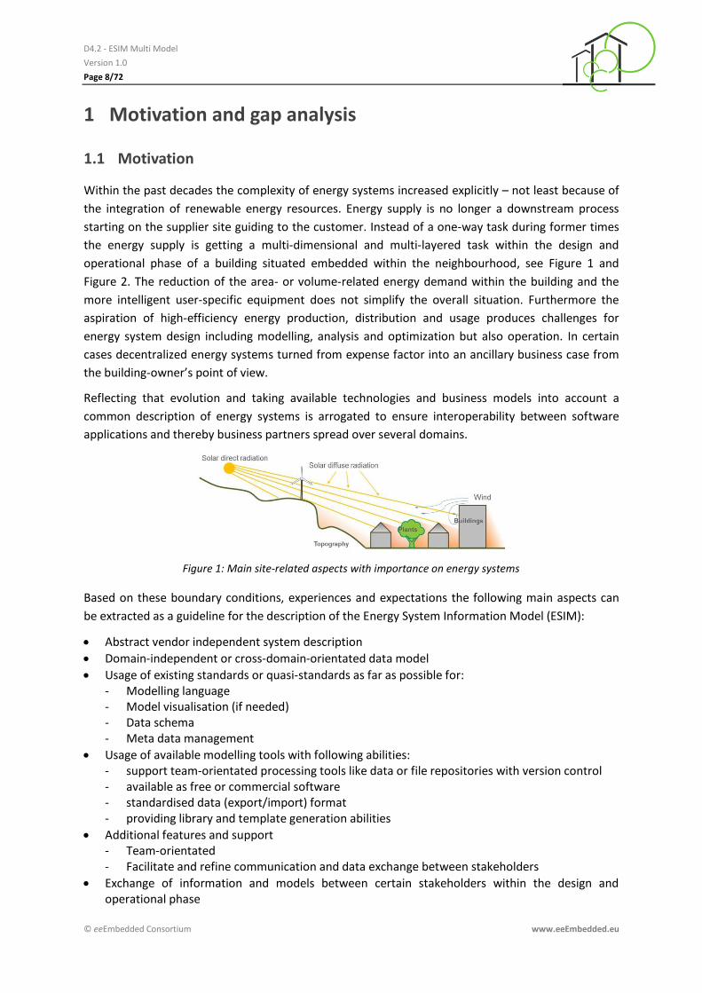
Within the past decades the complexity of energy systems increased explicitly – not least because of
the integration of renewable energy resources. Energy supply is no longer a downstream process
starting on the supplier site guiding to the customer. Instead of a one-way task during former times
the energy supply is getting a multi-dimensional and multi-layered task within the design and
operational phase of a building situated embedded within the neighbourhood, see Figure 1 and
Figure 2. The reduction of the area- or volume-related energy demand within the building and the
more intelligent user-specific equipment does not simplify the overall situation. Furthermore the
aspiration of high-efficiency energy production, distribution and usage produces challenges for
energy system design including modelling, analysis and optimization but also operation. In certain
cases decentralized energy systems turned from expense factor into an ancillary business case from
the building-owner’s point of view.
Reflecting that evolution and taking available technologies and business models into account a
common description of energy systems is arrogated to ensure interoperability between software
applications and thereby business partners spread over several domains.
Figure 1: Main site-related aspects with importance on energy systems
Based on these boundary conditions, experiences and expectations the following main aspects can
be extracted as a guideline for the description of the Energy System Information Model (ESIM):
Abstract vendor independent system description
Domain-independent or cross-domain-orientated data model
Usage of existing standards or quasi-standards as far as possible for: - Modelling language - Model visualisation (if needed) - Data schema - Meta data management
Usage of available modelling tools with following abilities: - support team-orientated processing tools like data or file repositories with version control - available as free or commercial software - standardised data (export/import) format - providing library and template generation abilities
Additional features and support - Team-orientated - Facilitate and refine communication and data exchange between stakeholders
Exchange of information and models between certain stakeholders within the design and operational phase
D4.2 - ESIM Multi Model
Version 1.0
Page 9/72
© eeEmbedded Consortium www.eeEmbedded.eu
Re-use of models
Ease up data exchange in horizontal (urban design – early design – detailed design phase- / energy system designer – HVAC designer – facility / energy manager) and vertical manner (system – subsystem – component)
Connection of conventional design steps, transient multi-domain spread analysis, operational tasks
Cover and transport of design-related static information and operation-related dynamical status data about energy systems
Covering of links between energy system information and boundary conditions like neighbourhood energy infrastructure, energy usage, weather/climate, price information, building construction, and, actors
Support the information flow and data exchange between systems, subsystems components situated inside the building as parts of the HVAC equipment but operated by the local energy supplier, e.g. heat pumps and CHP devices
Support of upcoming trends and business needs like B2BI (Business-to-Business-Integration) und A2A (Application-to-Application) coupling
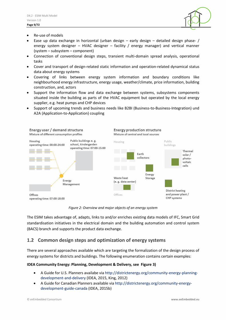
Figure 2: Overview and major objects of an energy system
The ESIM takes advantage of, adapts, links to and/or enriches existing data models of IFC, Smart Grid
standardisation initiatives in the electrical domain and the building automation and control system
(BACS) branch and supports the product data exchange.
1.2 Common design steps and optimization of energy systems
There are several approaches available which are targeting the formalization of the design process of
energy systems for districts and buildings. The following enumeration contains certain examples:
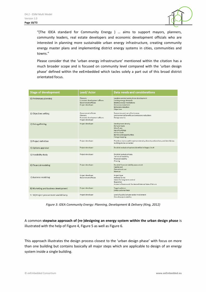
IDEA Community Energy: Planning, Development & Delivery, see Figure 3)
A Guide for U.S. Planners availabe via http://districtenergy.org/community-energy-planning-development-and-delivery (IDEA, 2015, King, 2012)
A Guide for Canadian Planners available via http://districtenergy.org/community-energy-development-guide-canada (IDEA, 2015b)
D4.2 - ESIM Multi Model
Version 1.0
Page 10/72
© eeEmbedded Consortium www.eeEmbedded.eu
“(The IDEA standard for Community Energy ) … aims to support mayors, planners,
community leaders, real estate developers and economic development officials who are
interested in planning more sustainable urban energy infrastructure, creating community
energy master plans and implementing district energy systems in cities, communities and
towns.”
Please consider that the ‘urban energy infrastructure’ mentioned within the citation has a
much broader scope and is focused on community level compared with the ‘urban design
phase’ defined within the eeEmbedded which tacles solely a part out of this broad district
orientated focus.
Figure 3: IDEA Community Energy: Planning, Development & Delivery (King, 2012)
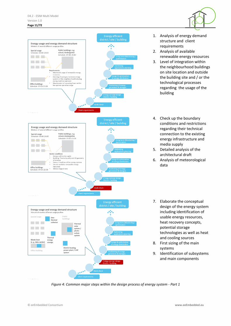
A common stepwise approach of (re-)designing an energy system within the urban design phase is
illustrated with the help of Figure 4, Figure 5 as well as Figure 6.
This approach illustrates the design process closest to the ‘urban design phase’ with focus on more
than one building but contains basically all major steps which are applicable to design of an energy
system inside a single building.
D4.2 - ESIM Multi Model
Version 1.0
Page 11/72
© eeEmbedded Consortium www.eeEmbedded.eu
1. Analysis of energy demand structure and client requirements
2. Analysis of available renewable energy resources
3. Level of integration within the neighbourhood buildings on site location and outside the building site and / or the technological processes regarding the usage of the building
4. Check up the boundary conditions and restrictions regarding their technical connection to the existing energy infrastructure and media supply
5. Detailed analysis of the architectural draft
6. Analysis of meteorological data
7. Elaborate the conceptual design of the energy system including identification of usable energy resources, heat recovery concepts, potential storage technologies as well as heat and cooling sources
8. First sizing of the main systems
9. Identification of subsystems and main components
Figure 4: Common major steps within the design process of energy system - Part 1
D4.2 - ESIM Multi Model
Version 1.0
Page 12/72
© eeEmbedded Consortium www.eeEmbedded.eu
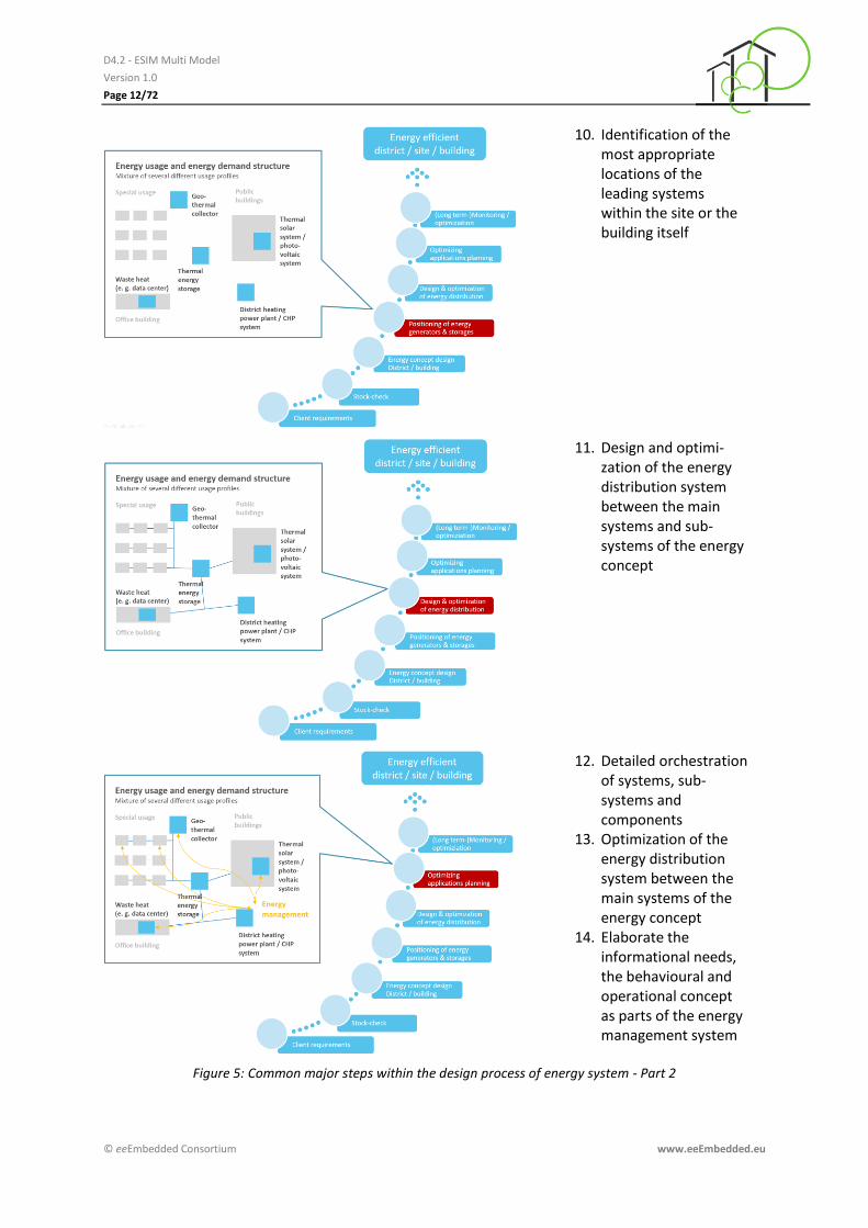
10. Identification of the most appropriate locations of the leading systems within the site or the building itself
11. Design and optimi-zation of the energy distribution system between the main systems and sub-systems of the energy concept
12. Detailed orchestration of systems, sub-systems and components
13. Optimization of the energy distribution system between the main systems of the energy concept
14. Elaborate the informational needs, the behavioural and operational concept as parts of the energy management system
Figure 5: Common major steps within the design process of energy system - Part 2
D4.2 - ESIM Multi Model
Version 1.0
Page 13/72
© eeEmbedded Consortium www.eeEmbedded.eu
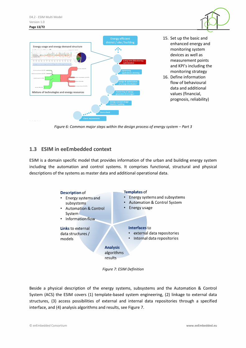
15. Set up the basic and enhanced energy and monitoring system devices as well as measurement points and KPI’s including the monitoring strategy
16. Define information flow of behavioural data and additional values (financial, prognosis, reliability)
Figure 6: Common major steps within the design process of energy system – Part 3
1.3 ESIM in eeEmbedded context
ESIM is a domain specific model that provides information of the urban and building energy system
including the automation and control systems. It comprises functional, structural and physical
descriptions of the systems as master data and additional operational data.
Figure 7: ESIM Definition
Beside a physical description of the energy systems, subsystems and the Automation & Control
System (ACS) the ESIM covers (1) template-based system engineering, (2) linkage to external data
structures, (3) access possibilities of external and internal data repositories through a specified
interface, and (4) analysis algorithms and results, see Figure 7.
D4.2 - ESIM Multi Model
Version 1.0
Page 14/72
© eeEmbedded Consortium www.eeEmbedded.eu
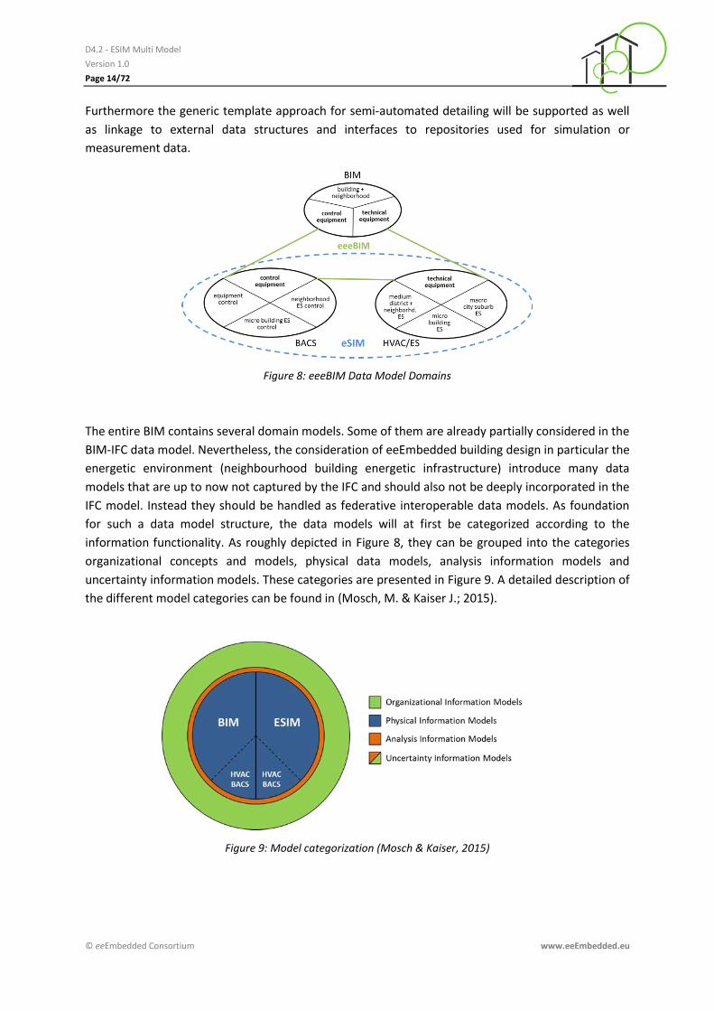
Furthermore the generic template approach for semi-automated detailing will be supported as well
as linkage to external data structures and interfaces to repositories used for simulation or
measurement data.
Figure 8: eeeBIM Data Model Domains
The entire BIM contains several domain models. Some of them are already partially considered in the
BIM-IFC data model. Nevertheless, the consideration of eeEmbedded building design in particular the
energetic environment (neighbourhood building energetic infrastructure) introduce many data
models that are up to now not captured by the IFC and should also not be deeply incorporated in the
IFC model. Instead they should be handled as federative interoperable data models. As foundation
for such a data model structure, the data models will at first be categorized according to the
information functionality. As roughly depicted in Figure 8, they can be grouped into the categories
organizational concepts and models, physical data models, analysis information models and
uncertainty information models. These categories are presented in Figure 9. A detailed description of
the different model categories can be found in (Mosch, M. & Kaiser J.; 2015).
Figure 9: Model categorization (Mosch & Kaiser, 2015)

D4.2 - ESIM Multi Model
Version 1.0
Page 15/72
© eeEmbedded Consortium www.eeEmbedded.eu
Common design phases identified within the eeEmbedded project
Figure 10 provides an overview about the identified use cases within the design process. Especially
the tasks related to the ESIM will be mentioned briefly within descriptions provided by the following
paragraphs.
More detailed descriptions of the design tasks within this use cases are provided by the eeEmbedded
deliverables D1.2 (Geißler et al., 2014) and D4.1 (Mosch & Kaiser, 2015).
Figure 10: Use cases identified within the eeEmbedded project, task with relation to ESIM are marked with red frame (left: urban design, mid: early design, right: detailed design)

D4.2 - ESIM Multi Model
Version 1.0
Page 16/72
© eeEmbedded Consortium www.eeEmbedded.eu
Use Case 1: Urban Design
Working tasks which are related to ESIM are situated within the row labelled with ‘2’, see Figure 11.
Within this use case the basic structure and subsystems of the energy system will be elaborated
based on the information provided by the architecture domain via the IFC model plus the client
requirements and taking into consideration the first analysis results elaborated within row number
‘6’.
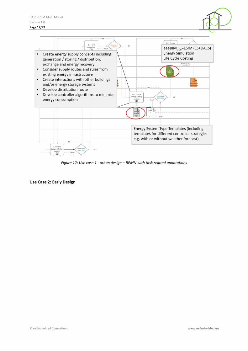
The outcome of this design step covers at first the energy supply concepts including generation, storing, and distribution. But also energy exchange and recovery facilities will be included if possible. Secondly pipe and duct routes and connecting points to existing energy infra-structure are considered and potential interactions with other buildings and/or energy systems will be addressed, see also Figure 12.
The energy system is described with the help of the ESIM including links to additional domain models.
Figure 11: Use case 1 - urban design (Geißler et al., 2014), task with relation to ESIM are marked with red frame
D4.2 - ESIM Multi Model
Version 1.0
Page 17/72
© eeEmbedded Consortium www.eeEmbedded.eu
Figure 12: Use case 1 - urban design – BPMN with task related annotations
Use Case 2: Early Design
D4.2 - ESIM Multi Model
Version 1.0
Page 18/72
© eeEmbedded Consortium www.eeEmbedded.eu
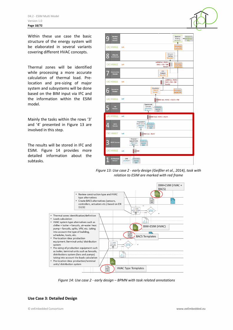
Within these use case the basic structure of the energy system will be elaborated in several variants covering different HVAC concepts.
Thermal zones will be identified while processing a more accurate calculation of thermal load. Pre-location and pre-sizing of major system and subsystems will be done based on the BIM input via IFC and the information within the ESIM model.
Mainly the tasks within the rows ‘3’ and ‘4’ presented in Figure 13 are involved in this step.
The results will be stored in IFC and ESIM. Figure 14 provides more detailed information about the subtasks.
Figure 13: Use case 2 - early design (Geißler et al., 2014), task with relation to ESIM are marked with red frame
Figure 14: Use case 2 - early design – BPMN with task related annotations
Use Case 3: Detailed Design
D4.2 - ESIM Multi Model
Version 1.0
Page 19/72
© eeEmbedded Consortium www.eeEmbedded.eu
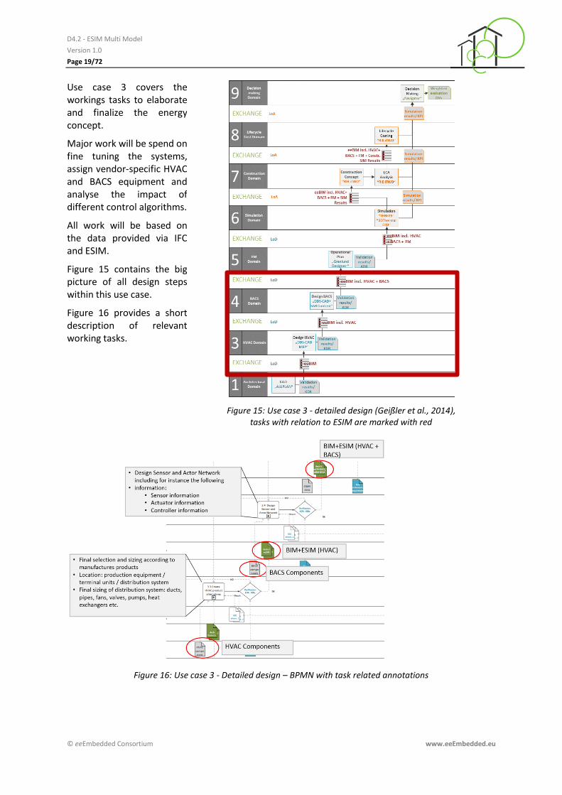
Use case 3 covers the workings tasks to elaborate and finalize the energy concept.
Major work will be spend on fine tuning the systems, assign vendor-specific HVAC and BACS equipment and analyse the impact of different control algorithms.
All work will be based on the data provided via IFC and ESIM.
Figure 15 contains the big picture of all design steps within this use case.
Figure 16 provides a short description of relevant working tasks.
Figure 15: Use case 3 - detailed design (Geißler et al., 2014), tasks with relation to ESIM are marked with red
Figure 16: Use case 3 - Detailed design – BPMN with task related annotations

D4.2 - ESIM Multi Model
Version 1.0
Page 20/72
© eeEmbedded Consortium www.eeEmbedded.eu
1.4 Gap analysis - Informational demands and collaboration requirements
The design of an energy system starts in the same way as that of the building envelop and the
constructional details - with a detailed analysis of site location, the existing neighbourhood and the
available resources in combination with the planned usage of the building. These main aspects are
roughly visualised within Figure 17. Within Figure 18 and Figure 19 certain aspects and informational
resources with high importance regarding the energy system design are summarized.
None of the existing domain specific models is able to handle all needed information an appropriate
manner. A solution will be possible while using link models for connecting the different domain
models plus the definition of an energy related model for the missing information which are not
parts of the existing models.
The following listing addresses these aspects and informational demands. These information are
closely related to exchange requirements discussed within eeEmbedded deliverable D1.3 (Calleja
Rodríguez et al., 2014).
Informational demand about energy system
Energy System, Sub-systems and components - Data of supply and disposal system - Interface description (physical, functional) - Risk information, reliability and sustainability information, see eeEmbedded
deliverable D3.1 (Gnüchtel et al., 2015)
Automation and Control System, Sub-Systems and components - Functional, behavioural description - Information flow: energy-related information, simulation and measured data, control
settings - Identifier description - Control strategies, see eeEmbedded deliverable D3.1 (Gnüchtel et al., 2015)
Figure 17: Informational demand and the relationship to ESIM
D4.2 - ESIM Multi Model
Version 1.0
Page 21/72
© eeEmbedded Consortium www.eeEmbedded.eu
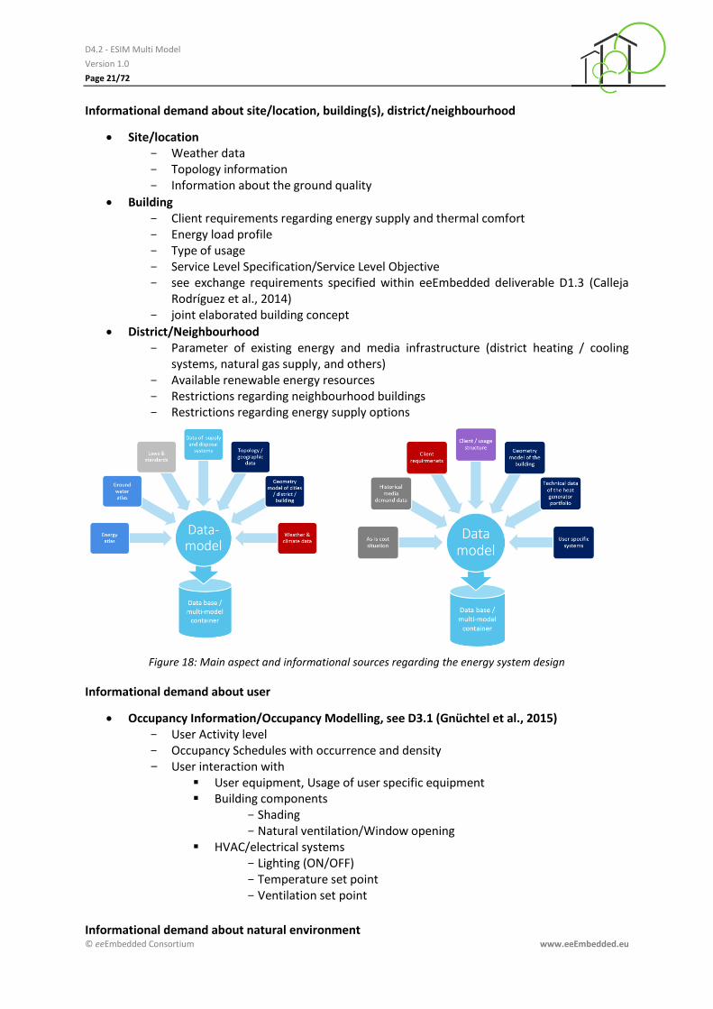
Informational demand about site/location, building(s), district/neighbourhood
Site/location - Weather data - Topology information - Information about the ground quality
Building - Client requirements regarding energy supply and thermal comfort - Energy load profile - Type of usage - Service Level Specification/Service Level Objective - see exchange requirements specified within eeEmbedded deliverable D1.3 (Calleja
Rodríguez et al., 2014) - joint elaborated building concept
District/Neighbourhood - Parameter of existing energy and media infrastructure (district heating / cooling
systems, natural gas supply, and others) - Available renewable energy resources - Restrictions regarding neighbourhood buildings - Restrictions regarding energy supply options
Figure 18: Main aspect and informational sources regarding the energy system design
Informational demand about user
Occupancy Information/Occupancy Modelling, see D3.1 (Gnüchtel et al., 2015) - User Activity level - Occupancy Schedules with occurrence and density - User interaction with
User equipment, Usage of user specific equipment Building components
- Shading - Natural ventilation/Window opening
HVAC/electrical systems - Lighting (ON/OFF) - Temperature set point - Ventilation set point
Informational demand about natural environment
D4.2 - ESIM Multi Model
Version 1.0
Page 22/72
© eeEmbedded Consortium www.eeEmbedded.eu
Energy atlas, ground water atlas
Topology/geographic data
Geothermal sources - Quality/quantity - Restrictions
Weather/Climate database - Regional long term prognosis - Local site-related historical data - Local site-related prognosis data - Climate elements (solar radiation , wind, …) - Restrictions
Potential Energy Sources - Quality/quantity - Restrictions
Informational demand about restriction/regulations by public local and regional laws and
standards
Restrictions/Limits - Caused by the site-related technical infrastructure - Caused by natural and technical / infrastructure in the existing neighbourhood
Public law - Local site-related - Regional - Governmental - Inter-governmental
Standards - Technical - Ecological
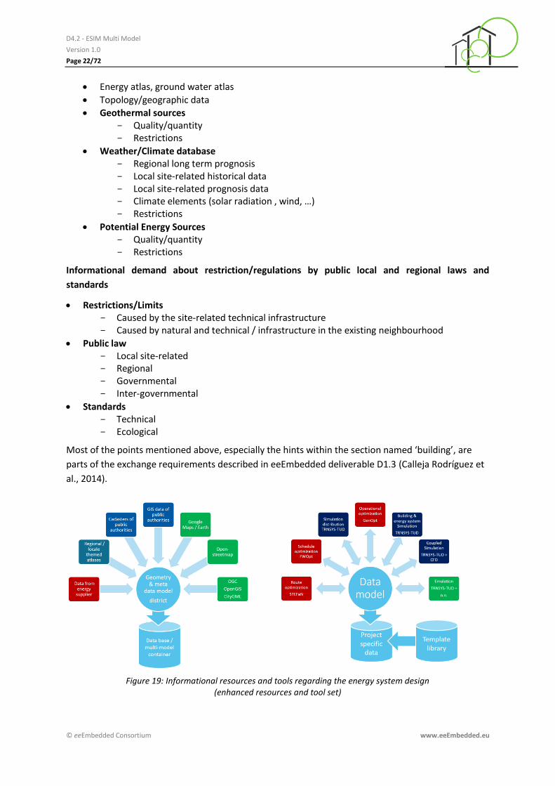
Most of the points mentioned above, especially the hints within the section named ‘building’, are
parts of the exchange requirements described in eeEmbedded deliverable D1.3 (Calleja Rodríguez et
al., 2014).
Figure 19: Informational resources and tools regarding the energy system design (enhanced resources and tool set)

D4.2 - ESIM Multi Model
Version 1.0
Page 23/72
© eeEmbedded Consortium www.eeEmbedded.eu
Advantages and challenges
Reviewing the gaps mentioned above several challenges arise; (1) integration of BIM (IFC) and ESIM,
(2) establishment of ESIM in the BIM-CAD tools as well as the simulation/analysis application, and (3)
apply the BIM-based design process within the ESIM domain.
The establishment of the ESIM gives an edge to interoperability between models and software tools
but also supports the implementation of an energy system lifecycle covering design, commissioning
and operation as well as retreat.
D4.2 - ESIM Multi Model
Version 1.0
Page 24/72
© eeEmbedded Consortium www.eeEmbedded.eu
2 Existing approaches related to energy system information modelling
2.1 Introduction
Currently there is no single model available which covers the description of all aspects of energy
systems in buildings and the neighbourhood from scratch. Various existing models already cover
certain aspects and provide data structures for enhancement or adaption to cover information which
are not originally part of the model content. Relevant examples of available models and standards
are listed below assigned to their domains:
Architecture/HVAC/BACS design domain
o IFC2x3/IFC4 model (ISO 16739)
HVAC design domain
o ISO 10628 and ISO 14617 – Piping and instrumentation diagram (P&ID)
o VDI 3805/ISO 16757 – Data structures for electronic building services product
catalogues
BACS design domain
o EN 15232 – Energy performance of buildings — Impact of Building Automation
Controls and Building Management
o ISO 16484 – Building automation and control systems BACS
o VDI 3813 – Building automation and control systems (BACS)
o Modelica mode
o ISO 16484-5 – BACnet
o ISO/IEC 14543-3 – KNX
Thermal Building Energy and System Simulation domain
o Modelica model
o Energy Plus data model (IDD, IDF)
o Green Building XML (gbXML)
Smart Grid domain
o Facility Smart Grid Information Model (FSGIM) UML
o Smart Grid Architecture Model (SGAM) SysML
o Several international ISO standards
Enterprise planning, business process modelling
o BPMN
Systems Engineering and IT project management
o UML / SysML
o Energy System Language
o Universal System Language
o ISO/IEC 15288 – Description of the processes of the systems life cycle.
Because of the relevance for the modelling of energy systems of certain standards or modelling
approaches will be described more in detail within the following
D4.2 - ESIM Multi Model
Version 1.0
Page 25/72
© eeEmbedded Consortium www.eeEmbedded.eu
2.2 Standards, ontologies and related projects
Certain relevant most relevant standards listed above will be introduced briefly.
VDI 3813 – Building automation and control systems (BACS) – (BACS design domain)
The German guideline VDI 3813 applies to room control applications in the field of building services.
The guideline is defining Room Automation (RA) functions which are grouped into different function
groups (sensor functions, actuator functions, operator and display functions, application functions,
management functions, and service and diagnosis functions). Each RA function can be seen as a black
box including an interface description (VDI3813).
EN 15232
This European Standard EN 15232 provides a structured list of control, building automation and
technical building management functions which have an impact on the energy performance of
buildings and the technical building system (EN 15232). Using BAC Efficiency Classes (A, B, C, and D)
of building automation and technical building management functions the required building energy
performance can be achieved. The EN 15232 provides a promising basis for a functional description
of building automation and control systems which can be covered by BACS models.
ISO 16484
The international standard ISO 16484 provides a guideline for integrated planning and operation of
building automation and control systems. The standard defines BACS hardware, BACS functions and a
data communication protocol (BACnet) (ISO 16484).
ISO 16484-5 (BACnet), ISO/IEC 14543-3 (KNX)
Common ISO standards to interface building control devices used to control HVAC and Electro
installations systems. Special designed and proprietary software access these standard protocols to
program BACS devices with the intension of controlling its connected HVAC products and systems to
act as required in the physical constructed building. In theory, the HVAC domain experts can set BACS
generic controlling data according to ES results to optimize the HVAC systems in the model.
Piping and instrumentation diagram (ISO 10628 and ISO 14617)
The piping and instrumentation diagram (P&ID) is a common schematic representation in the process
industry which shows the piping of the process flow together with the installed equipment (e.g.
vessels, fans and pumps) and instrumentation (e.g. sensors and controller). The international
standards ISO 10628 – Diagrams for the chemical and petrochemical industry and ISO 14617 –
Graphical symbols for diagrams provide the appropriated symbol definitions (ISO 10628, ISO 14617).
ISO 16757 (VDI 3805)
These standards covers data structures for electronic building services product catalogues. The
standard is based on the German norm VDI 3805 which targets the exchange of product model data
within the HVAC branch. Currently there are only the first two parts of the standard available
describing the main idea as well as the geometry of physical products/devices. Further parts are
announced later on.
SEMANCO Energy Model
D4.2 - ESIM Multi Model
Version 1.0
Page 26/72
© eeEmbedded Consortium www.eeEmbedded.eu
The SEMANCO Energy Model is a formal ontology – specified using Web Ontology Language 2 (OWL
2) – comprising concepts captured from diverse sources including standards, use cases and activity
descriptions and data sources related to the domains of urban planning and energy management.
Close to the modelling of energy systems several domains still exist developing own data models:
Ambient Assisted Living (AAL)
Smart Home
Additionally the following projects are targeting topics which are partly close by to the intensions of
ESIM
Future Internet for Smart Energy – FINSENY (FINSENY, 2011); http://www.fi-ppp-finseny.eu/standardisation/ and http://www.finesce.eu/FINSENY.html
En-trust http://www.en-trust.at/
Integrated Smart Grid Reference Architecture for Intelligent Distribution Grids and Virtual Power Plants (INTEGRA) http://www.offis.de/struktur/projekte/integra.html
FINESCE (Future INtErnet Smart Utility ServiCEs) (FINESCE, 2015)
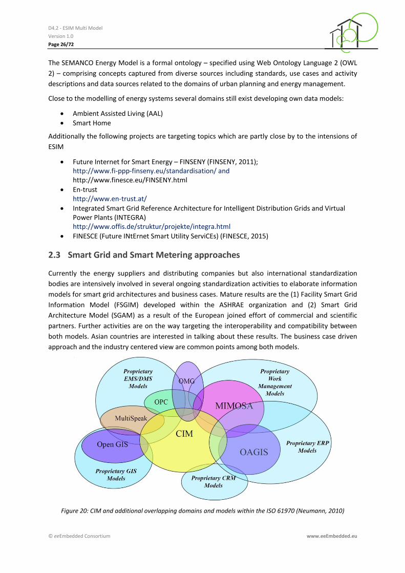
2.3 Smart Grid and Smart Metering approaches
Currently the energy suppliers and distributing companies but also international standardization
bodies are intensively involved in several ongoing standardization activities to elaborate information
models for smart grid architectures and business cases. Mature results are the (1) Facility Smart Grid
Information Model (FSGIM) developed within the ASHRAE organization and (2) Smart Grid
Architecture Model (SGAM) as a result of the European joined effort of commercial and scientific
partners. Further activities are on the way targeting the interoperability and compatibility between
both models. Asian countries are interested in talking about these results. The business case driven
approach and the industry centered view are common points among both models.
Figure 20: CIM and additional overlapping domains and models within the ISO 61970 (Neumann, 2010)
D4.2 - ESIM Multi Model
Version 1.0
Page 27/72
© eeEmbedded Consortium www.eeEmbedded.eu
In the middle of the standardization effort within the smart grid domain stands the Common
Information Model (CIM). Figure 20 illustrates the overlapping of the CIM with other closely related
domains with high importance of the business architecture within the electrical energy domain.
The following list contains major international standards which are partly under construction. Some
subparts are just announced but not available yet. Major standards with strong relationship to the
Smart Grid domain are briefly summarized as follows:
IEC 62357 – Seamless Integration Reference Architecture (SIA)
IEC 61970/61968 – Common Information Model (CIM)
IEC 61850 – Substation Automation, Distributed Energy Resources
IEC 62351 – Security
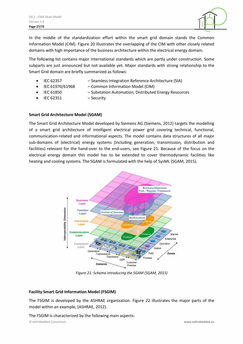
Smart Grid Architecture Model (SGAM)
The Smart Grid Architecture Model developed by Siemens AG (Siemens, 2012) targets the modelling
of a smart grid architecture of intelligent electrical power grid covering technical, functional,
communication-related and informational aspects. The model contains data structures of all major
sub-domains of (electrical) energy systems (including generation, transmission, distribution and
facilities) relevant for the hand-over to the end-users, see Figure 21. Because of the focus on the
electrical energy domain this model has to be extended to cover thermodynamic facilities like
heating and cooling systems. The SGAM is formulated with the help of SysML (SGAM, 2015).
Figure 21: Schema introducing the SGAM (SGAM, 2015)
Facility Smart Grid Information Model (FSGIM)
The FSGIM is developed by the ASHRAE organization. Figure 22 illustrates the major parts of the
model within an example, (ASHRAE, 2012).
The FSGIM is characterized by the following main aspects:

D4.2 - ESIM Multi Model
Version 1.0
Page 28/72
© eeEmbedded Consortium www.eeEmbedded.eu
Abstract representation of the energy consuming, producing, and storage systems
Modelling the energy characteristics of the equipment, energy characteristics are communicated with a protocol
Detailed information about systems inside the facility (directly managed), e.g. HVAC, lighting, security, facility management systems, and industrial automation systems
Details about external systems that the facility interacts with (no direct control), e.g. weather information, real-time energy pricing information, demand response signals, and sources of energy usage information
Enables interaction between energy provider and facilities in a common way
The model is based on certain major components (Building Blocks):
Generator Component
Meter Component
Load Component
Energy Management Component
These modelling components can be arranged and combined as needed to represent physical devices, systems, or functions.
In addition to the major components FSGIM integrates model elements from external sources:
Energy Interoperation Component - wd36/PR03
Energy Market Information Exchange - EMIX PR04
Calendar Information model of WS - ws-calendar-CS01
Substation Automation, Distributed Energy Resources (international standard for communi-cations with electric power and related system intelligent electric devices ) - IEC 61850
Energy Usage Information Model - NAESB PAP10 EUI
Weather Exchange Model - WXXM
Figure 22: Example for the modular structure of the FSGIM (ASHRAE, 2012)
Smart Metering
The smart metering approach can be esteemed as an important add-on of the smart grid domain on
the way of integrating thermal energy and natural gas-related energy infrastructures. Smart metering
D4.2 - ESIM Multi Model
Version 1.0
Page 29/72
© eeEmbedded Consortium www.eeEmbedded.eu
offers several possibilities for a more intelligent way of operating energy systems not only on district
but also on building level.
Main drivers within the smart metering domain are the field of machine to machine (M2M) commu-
nication and the standardization effort by the European Telecommunications Standards Institute
(ETSI).
Especially the standards describing the information exchange and the description of measurement
equipment are relevant for the ESIM.
2.4 Smart City modelling
Within the approach of modelling communal infrastructures and related aspects of Smart Cities the
energy infrastructure and the building stock are representing parts of the city model. These activities
will be coordinated by the ISO/IEC Joint Technical Committee 1 - Task Group „Reference Architecture
Model“. This kind of view includes the energy related infrastructure in the buildings neighbourhood
and is used to model the structure and behaviour of smart cities. Currently there are several
intensions for an international standardisation on the district and city level. A roadmap to the Smart
Cities approach is delivered in (DIN & DKE, 2015). These activities of further development are on the
run and have to be observed to integrate the results into the ESIM context later on.
In this context buildings and energy systems within buildings can be described with a rough building-
centred view focusing the energy systems within the neighbourhood and ending up on the supply
company's substations inside the building.
2.5 Building Information Modelling (BIM)
The Industry Foundation Classes (IFC), an international standard for the exchange of BIM data, are
providing a generic data schema that covers among others architectural, building service and
structural elements. Since the release of the IFC4 schema specification the data structure provides
enhanced capabilities for the modelling of building service systems. System modelling using e.g. port
connection concepts is available. Serialized IFC models are provided either in STEP physical file
format (SPF) or as ifcXML file. IFC also covers a wide range of generic HVAC type devices, instances
and attributes to match a specific product. The IFC4 schema model is improved in several aspects,
both in content and exchange: It enhances the capability of the IFC specification in its main
architectural, building service and structural elements with new geometric, parametric and other
features. It furthermore enables numerous new BIM workflows – including 4D and 5D model
exchanges, product libraries, BIM to GIS interoperability, enhanced thermal simulations and
sustainability assessments. The improvement of space boundaries and the introduction of additional
spatial zones and external spaces (against ground, water, air) as well as the descriptiveness of
shading devices can be used for energy and other performance analysis. In addition to the EXPRESS
schema, the ifcXML4 schema is fully integrated into the IFC4 specification. The additional full
integration of the new mvdXML technology easily enables the definition of data validation services
for IFC4 data submissions. The mvdXML is an add-on to the IFC schema to describe Model View
Definitions as a subset of an entire IFC model.
Since the release of the IFC4 schema specification the data structure provides now enhanced
capabilities in modelling building automation and control systems and their components.
D4.2 - ESIM Multi Model
Version 1.0
Page 30/72
© eeEmbedded Consortium www.eeEmbedded.eu
2.6 Systems engineering approach
Energy systems are getting more and more complex because of the ambitious building design, the
available sophisticated energy technology and the challenging client requirements which turn every
building into a unique product. On the other hand a trend using modularization approaches and
building blocks within the construction domain as well as the HVAC and BACS branch have to be
recognized. As third main aspect the integration and penetration of IT technology within most parts
of the building with have to be mentioned. In conjunction with the attempt to cross-domain and
cross-project standardization of the processes around a building covering design and operation
purposes, all partners are highly motivated to implement, review and speed-up their processes.
These intentions force optimized information and data flow including interoperability of models and
applications.
A promising solution covering the mentioned aspects and challenges is provided by the cross-domain
orientated approach of Systems Engineering (SE).
SE addresses among other details the following aspects:
Requirements management
Structuring into systems, subsystems, components, ports, blocks, types, units
Use case elaboration
System design
Revision management
System testing
Verification and validation, quality assurance
Risk management
System documentation
Standardized structures and diagrams
The data are organized within different sub models (Weilkiens, 2014).
Requirement Model o Specifications o Uses Cases o Interactions o State Machines o Constraints
Operational Domain Model
Design Model
Implementation Model
Library
Basic model components in systems engineering
2.6.1
SysML – basic structures and components
2.6.2
The SE approach provides the System Modelling Language (SysML) based on the Unified Modelling
Language (UML 2). Both languages are maintained and developed by the Object Management
Group® (OMG®). The last official Version 1.3 of SysML was released by OMG in 2012, (OMG, 2012). In
November 2013 the next version 1.4 was released as beta version (OMG, 2013) which includes some
significant enhancements. Currently the available software tools provide support for version 1.3.

D4.2 - ESIM Multi Model
Version 1.0
Page 31/72
© eeEmbedded Consortium www.eeEmbedded.eu
Figure 23: Interrelationship between UML and SysML (OMG, 2012)
Within the following list the diagrams of SysML 1.3 will be introduced.
Package diagram This diagram type represents the organization of a model in terms of packages that contain model elements, see Figure 24.
Figure 24: Example - Package diagram (SysML 1.3)
Requirement diagram This diagram type represents text-based requirements and their relationship with other requirements, design elements, and test cases to support requirements traceability, Figure 25.
Figure 25: Example - Requirement diagram (SysML 1.3)
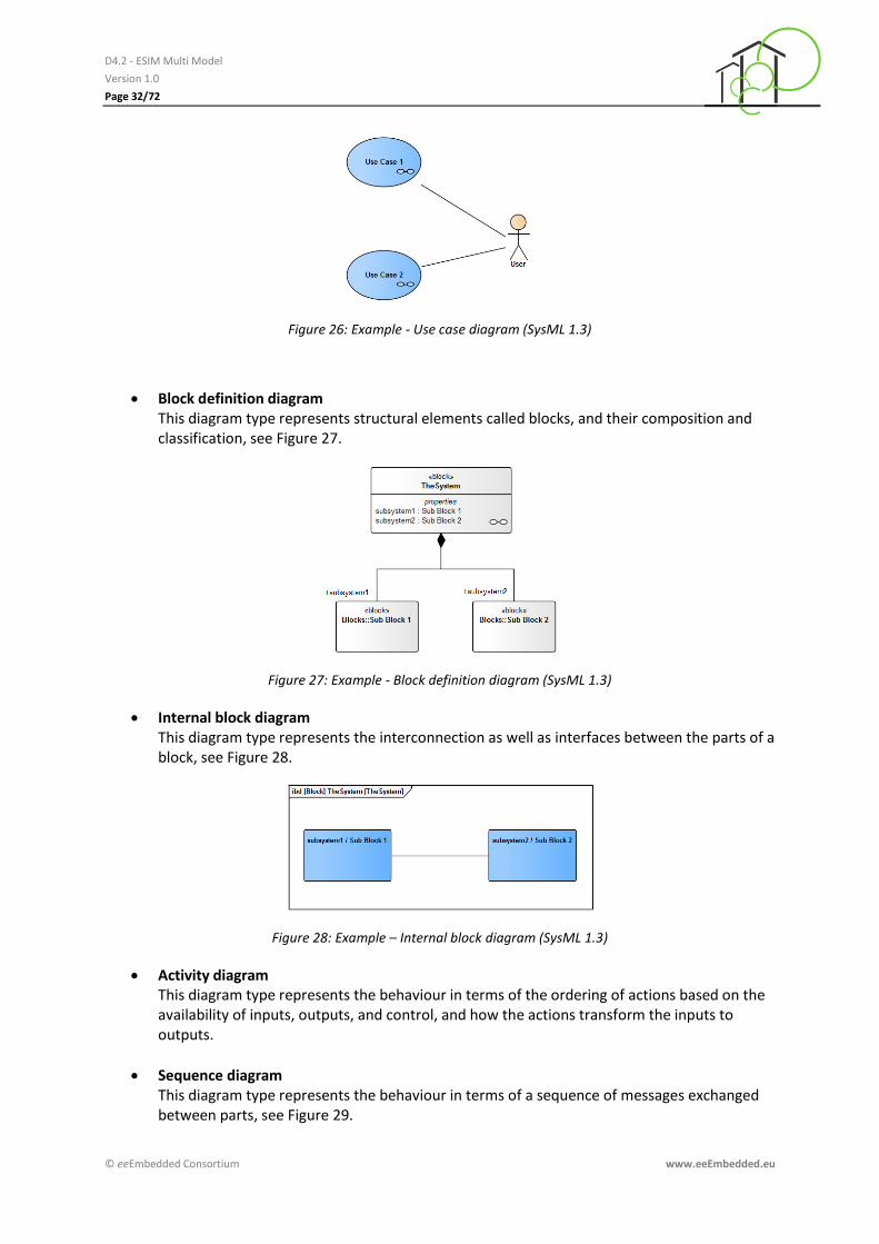
Use case diagram This diagram type represents functionality in terms of how a system or other entity is used by external entities (i.e., actors) to accomplish a set of goals, see Figure 26.
D4.2 - ESIM Multi Model
Version 1.0
Page 32/72
© eeEmbedded Consortium www.eeEmbedded.eu
Figure 26: Example - Use case diagram (SysML 1.3)
Block definition diagram This diagram type represents structural elements called blocks, and their composition and classification, see Figure 27.
Figure 27: Example - Block definition diagram (SysML 1.3)
Internal block diagram This diagram type represents the interconnection as well as interfaces between the parts of a block, see Figure 28.
Figure 28: Example – Internal block diagram (SysML 1.3)
Activity diagram This diagram type represents the behaviour in terms of the ordering of actions based on the availability of inputs, outputs, and control, and how the actions transform the inputs to outputs.
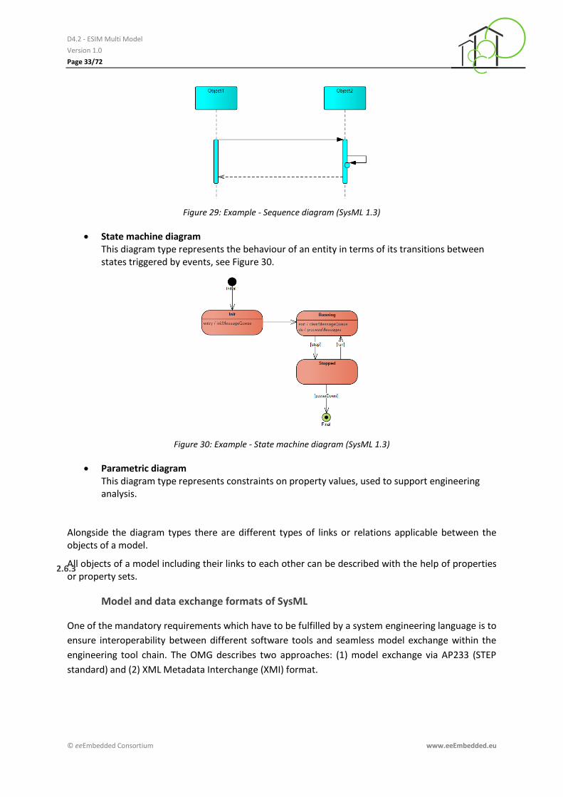
Sequence diagram This diagram type represents the behaviour in terms of a sequence of messages exchanged between parts, see Figure 29.
D4.2 - ESIM Multi Model
Version 1.0
Page 33/72
© eeEmbedded Consortium www.eeEmbedded.eu
Figure 29: Example - Sequence diagram (SysML 1.3)
State machine diagram This diagram type represents the behaviour of an entity in terms of its transitions between states triggered by events, see Figure 30.
Figure 30: Example - State machine diagram (SysML 1.3)
Parametric diagram This diagram type represents constraints on property values, used to support engineering analysis.
Alongside the diagram types there are different types of links or relations applicable between the objects of a model.
All objects of a model including their links to each other can be described with the help of properties or property sets.
Model and data exchange formats of SysML
2.6.3
One of the mandatory requirements which have to be fulfilled by a system engineering language is to
ensure interoperability between different software tools and seamless model exchange within the
engineering tool chain. The OMG describes two approaches: (1) model exchange via AP233 (STEP
standard) and (2) XML Metadata Interchange (XMI) format.
D4.2 - ESIM Multi Model
Version 1.0
Page 34/72
© eeEmbedded Consortium www.eeEmbedded.eu
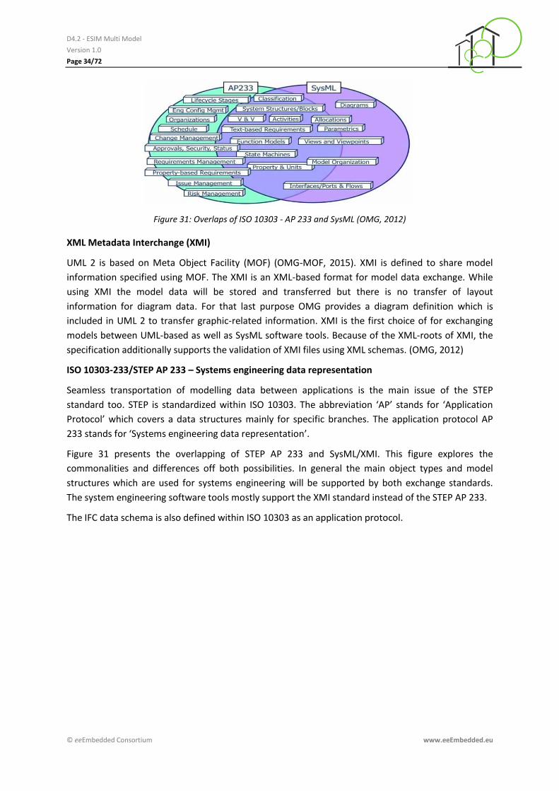
Figure 31: Overlaps of ISO 10303 - AP 233 and SysML (OMG, 2012)
XML Metadata Interchange (XMI)
UML 2 is based on Meta Object Facility (MOF) (OMG-MOF, 2015). XMI is defined to share model
information specified using MOF. The XMI is an XML-based format for model data exchange. While
using XMI the model data will be stored and transferred but there is no transfer of layout
information for diagram data. For that last purpose OMG provides a diagram definition which is
included in UML 2 to transfer graphic-related information. XMI is the first choice of for exchanging
models between UML-based as well as SysML software tools. Because of the XML-roots of XMI, the
specification additionally supports the validation of XMI files using XML schemas. (OMG, 2012)
ISO 10303-233/STEP AP 233 – Systems engineering data representation
Seamless transportation of modelling data between applications is the main issue of the STEP
standard too. STEP is standardized within ISO 10303. The abbreviation ‘AP’ stands for ‘Application
Protocol’ which covers a data structures mainly for specific branches. The application protocol AP
233 stands for ‘Systems engineering data representation’.
Figure 31 presents the overlapping of STEP AP 233 and SysML/XMI. This figure explores the
commonalities and differences off both possibilities. In general the main object types and model
structures which are used for systems engineering will be supported by both exchange standards.
The system engineering software tools mostly support the XMI standard instead of the STEP AP 233.
The IFC data schema is also defined within ISO 10303 as an application protocol.

D4.2 - ESIM Multi Model
Version 1.0
Page 35/72
© eeEmbedded Consortium www.eeEmbedded.eu
3 Definition and concept of the Energy System Information Model
3.1 Introduction
The Energy System Information Model (ESIM) takes up several general high-level aspects which
characterise an informational model:
identify and describe objects in both ways, a vendor- and application-independent manner
mapping objects
cover the objects properties and
also cover the operations of the objects
An information model is a superset of a data model. Objects to be managed within an informational
model could be domain-specific devices, e.g. router, hubs and switches within the IT domain or
boilers, heat pumps or similar devices within the energy domain. Typical devices with a cross-
domain-character are connectors or ports.
Major tasks of an information model except the design phase support are observation/monitoring,
configuration and (remote) control using an abstract unique view and ensure a vendor-independent
handling of devices of the same type.
Mostly informational models consist of a Management Information Base (MIB) which covers all data
and information within a data structure and a management protocol.
A starting point for build-up an information model of energy systems is the Common Information
Model (CIM) published by the Distributed Management Task Force (DMTF) for the management of IT
systems. The standardisation intension of the International Electrotechnical Commission IEC is closely
related to this approach which led to the standard IEC 61970 covering the needs of the electrical
energy supply.
The informational model will be combined with a functional model covering the following additional
management tasks (=FCAPS): (1) fault, (2) configuration, (3) accounting, (4) performance, and (5)
security.
Compared with the introduced Smart Grid modelling approaches the ESIM has to cover thermal and
electrical related information but also certain boundary conditions. Relations to other domains and
data modelled outside the ESIM will be covered using a multi-model approach.
Within the eeEmbedded context the ESIM joins or connects information of certain data sources and
domains (see Figure 32):
- Building model (IFC) - Neighbourhood Information Model (NIM) - BACS/HVAC (IFC) - Others
Climate Prices User behaviour

D4.2 - ESIM Multi Model
Version 1.0
Page 36/72
© eeEmbedded Consortium www.eeEmbedded.eu
Figure 32: Shell Model showing the overlapping areas between ESIM, BIM and NIM
The Multi-Model approach will be introduced in more detail within the following section.
The ESIM model has to be applicable without the availability of detailed building construction
information provided via IFC because of the rare existence of an IFC model for the building stock.
Within the ESIM certain aspects are forming a core part covering relevant data which are close
related to the design process with a mandatory character. Additionally there are aspects outside the
core representing data which are optionally modelled within the design process.
In general ESIM follows the structuring approach of IFC if there are data structures available. Nevertheless restrictions for further extending the IFC standard were announced. Reviewing requirements and boundary conditions for modelling energy system several the needs will be addressed:
• ESIM should be usable as standalone model without the need of on building model described with IFC
• ESIM should cover interfaces to HVAC and BACS components and other devices • Integration of measured/aggregated measured operational/prognosis data • ESIM should support a simplified non-graphical representation of buildings, systems,
subsystems, user behaviour • Referencing ESIM from IFC and vice versa • Using SPARQL to query data and provide it in a specific IFC MVD or MMC
The ESIM will use the system engineering approach and the language SysML introduced in 2.6.
3.2 Multi-model approach
As mentioned above the ESIM will be connected with other domain models via a link model
approach. These domain or elementary models are the (1) Architectural Model, (2) Neighbourhood
Model, (3) HVAC Model, (4) BACS Model, (5) Climate Model or (6) Simulation Model, defined in
(Mosch, M. & Kaiser J.; 2015). Within the eeEmbedded project the architectural and the
neighbourhood model are fully covered by the IFC data exchange standard (IFC4). Furthermore IFC
D4.2 - ESIM Multi Model
Version 1.0
Page 37/72
© eeEmbedded Consortium www.eeEmbedded.eu
represents a subset of the HVAC and BACS domain model, e.g. location in the building and the
geometrical representation of the corresponding HVAC or BACS object respectively.
Figure 33: ESIM Multi-Model Approach – eeEmbedded related link model approach
While using the ESIM within the eeEmbedded framework the link model plays a central role
connecting different resources and data models, see Figure 33.
The applied link model will be as flexible as possible to cover the heterogeneous relations between
the architecture, the energy systems and room automation & control system and components at
different layers:
- Via spatial structure provided by IFC - Via physical connection provided by IFC and ESIM (pipes, canals, cables, medium
flow) - Via informational connection provided by IFC and ESIM (measured values,
algorithms) - Via service concepts (facility management tasks) - others
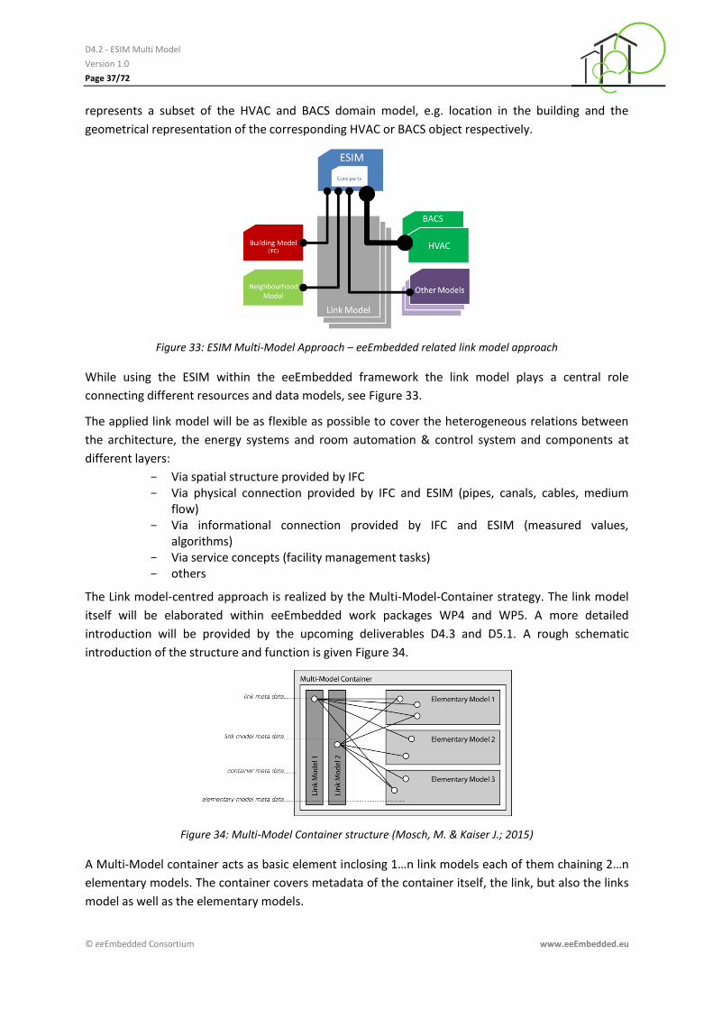
The Link model-centred approach is realized by the Multi-Model-Container strategy. The link model
itself will be elaborated within eeEmbedded work packages WP4 and WP5. A more detailed
introduction will be provided by the upcoming deliverables D4.3 and D5.1. A rough schematic
introduction of the structure and function is given Figure 34.
Figure 34: Multi-Model Container structure (Mosch, M. & Kaiser J.; 2015)
A Multi-Model container acts as basic element inclosing 1…n link models each of them chaining 2…n
elementary models. The container covers metadata of the container itself, the link, but also the links
model as well as the elementary models.

D4.2 - ESIM Multi Model
Version 1.0
Page 38/72
© eeEmbedded Consortium www.eeEmbedded.eu
Within the eeEmbedded project we assume that all relevant information provided by additional
domains will be available. Projects targeting refurbishment tasks in the building stock or focusing
optimization issues on energy systems have to be able to manage less amount and/or a lower quality
of data especially regarding the IFC model and/or the neighbourhood description. Nevertheless the
ESIM should be applicable within this use case too.
The following listing shows the listing of the most relevant elementary models from ESIM point of
view.
Architectural/Building Model (IFC)
Neighbourhood Model (IFC)
HVAC Model (IFC, ESIM)
BACS Model (IFC, ESIM)
Climate Model
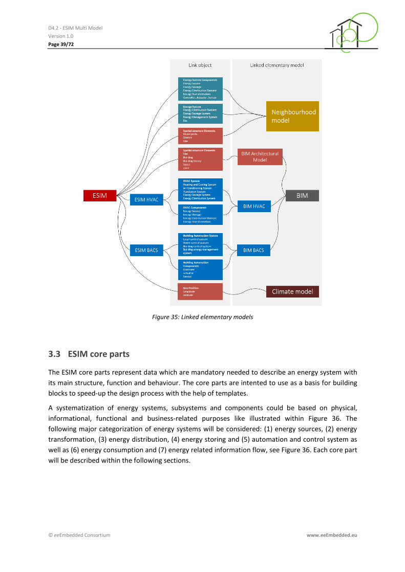
In order to follow the intended Multi-Model approach appropriated link objects among the different
elementary models have to be defined. Therefore different kinds of links will be identified and
elaborated in eeEmbedded Task 4.3 “Link Model” (D4.3). The related different types of relations and
relationship objects will be developed and the requirements for the link attributes and the
transformation and mapping functions will be defined. Based on the link model, the link model
relation types the interoperability link points (a set of key objects) for each domain model will be
developed in Task 5.2 “Interoperability of domain models”. The following Table provides a rough
overview on possible links to the mentioned elementary models, see Figure 35.
D4.2 - ESIM Multi Model
Version 1.0
Page 39/72
© eeEmbedded Consortium www.eeEmbedded.eu
Figure 35: Linked elementary models
3.3 ESIM core parts
The ESIM core parts represent data which are mandatory needed to describe an energy system with
its main structure, function and behaviour. The core parts are intented to use as a basis for building
blocks to speed-up the design process with the help of templates.
A systematization of energy systems, subsystems and components could be based on physical,
informational, functional and business-related purposes like illustrated within Figure 36. The
following major categorization of energy systems will be considered: (1) energy sources, (2) energy
transformation, (3) energy distribution, (4) energy storing and (5) automation and control system as
well as (6) energy consumption and (7) energy related information flow, see Figure 36. Each core part
will be described within the following sections.

D4.2 - ESIM Multi Model
Version 1.0
Page 40/72
© eeEmbedded Consortium www.eeEmbedded.eu
Figure 36: Identification of ESIM core parts as main categories
Following this approach presented in Figure 36 a simple energy system shown in Figure 37 will be
separated as indicated with the help of the coloured background.
Figure 37: Simplified example schema of energy system
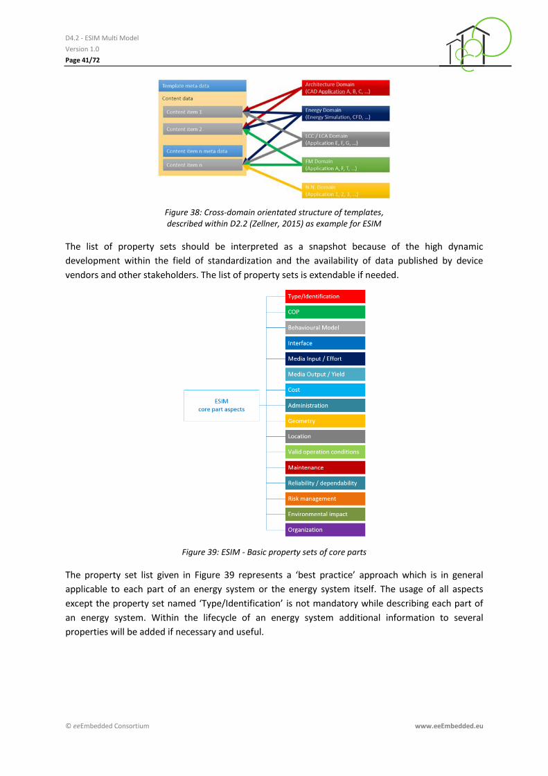
Because of the various interdependencies of an energy system the ESIM has to provide data
structures to support a cross-domain orientated usage of data describing an energy system. As
introduced in the eeTemplate context an ESIM property set is structured to support this
requirement, please refer to Figure 38. The description of each core part within an energy system is
based on re-usable property sets. Figure 39 contains an overview about main property sets of energy
systems core parts. The property sets are described briefly within Table 1.
D4.2 - ESIM Multi Model
Version 1.0
Page 41/72
© eeEmbedded Consortium www.eeEmbedded.eu
Figure 38: Cross-domain orientated structure of templates, described within D2.2 (Zellner, 2015) as example for ESIM
The list of property sets should be interpreted as a snapshot because of the high dynamic
development within the field of standardization and the availability of data published by device
vendors and other stakeholders. The list of property sets is extendable if needed.
Figure 39: ESIM - Basic property sets of core parts
The property set list given in Figure 39 represents a ‘best practice’ approach which is in general
applicable to each part of an energy system or the energy system itself. The usage of all aspects
except the property set named ‘Type/Identification’ is not mandatory while describing each part of
an energy system. Within the lifecycle of an energy system additional information to several
properties will be added if necessary and useful.

D4.2 - ESIM Multi Model
Version 1.0
Page 42/72
© eeEmbedded Consortium www.eeEmbedded.eu
Table 1: ESIM aspects - Properties/Property sets
Type/Identification Machine readable as well as human readable identification and classification is provided by this mandatory property set.
COP The (normative) Coefficient of Performance (COP) represents a major criteria especially within the design process. Often COP values valid for maximum, minimum and partial load are provided by device vendors depending on the type of device or technology.
Behavioural model According to the abilities provided in VDI 3805 and the upcoming ISO 16757 standard behavioural characteristics could be included by device vendors, suppliers, service providers, designers or customers.
Interface For seamless technical and informational integration of devices into an energy concept the specification of physical and IT-related interfaces will be described within this property set according to ISO 16484-5 (BACnet) and ISO/IEC 14543-3 (KNX) as well as VDI 3805 and ISO 16757.
Media Input/Effort The description of (nominal) medium input into devices with differentiation between quality (e.g. temperature, pressure, informational protocol) and quantity (volume flux or heat flux, data stream) is situated in this aspect.
Media Output/Yield The description of (nominal) medium output of devices with differentiation between quality (e.g. temperature, pressure, informational protocol) and quantity (volume flux, heat flux, or data stream) is situated in this aspect.
Cost This property set contains the sales price of a devices and (nominal) operational costs – if provided by the vendor. For the operational cost a rated value depending on the investment cost is commonly used too.

D4.2 - ESIM Multi Model
Version 1.0
Page 43/72
© eeEmbedded Consortium www.eeEmbedded.eu
Administration This property set contains information with administrative character which are used for management purposes, e.g. rent of system, business cases which includes contracting models. Additional information to standards or national law could be added within this aspect.
Valid operational conditions Most vendors of technical systems and components restrict the usage of their products while formulating valid operational conditions related to the medium and /or the ambient.
Geometry If needed the geometry of a device will be modelled according to the ISO 10303 standard.
Location Depending on the type of device or system or the point of view the exact position is needed. For energy supply systems located in the neighbourhood the usage of geo coordinates is appropriate. Inside the building the usual way of referencing the position of a reference point of a device is done by x-y-z coordinates.
Maintenance This aspect provides data structures for the description of maintenance related task during the operational phase of the system. The common used categories are supported: (1) vendor advices, and (2) client specific requirements related to the maintenance strategy as well as (3) requirements by law. (DIN EN 13306)
Reliability/dependability The design of sophisticated energy systems or sensible use cases mostly includes a reliability analysis based on certain key values which will be located within this property set. (IEC 60050 and other standards)
Risk management Depending on the use case the management of risk is becoming an essential part of the design and construction management. Therefore certain information is needed and located within this aspect. (ISO 31000)
D4.2 - ESIM Multi Model
Version 1.0
Page 44/72
© eeEmbedded Consortium www.eeEmbedded.eu
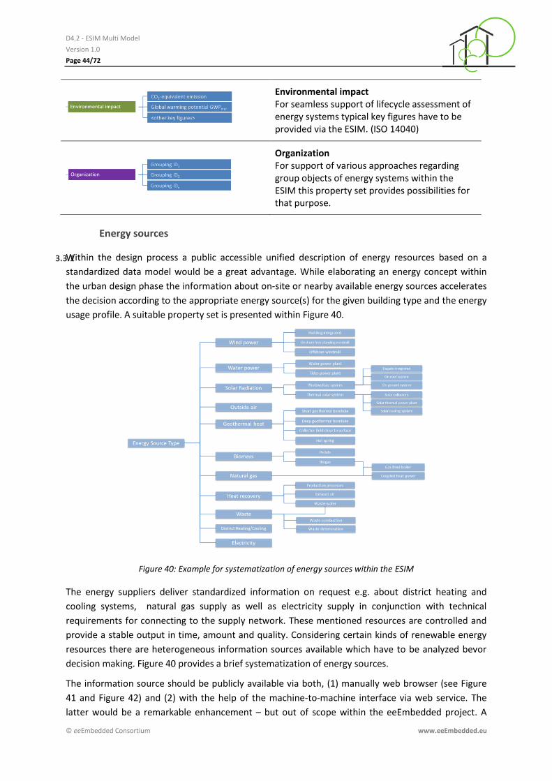
Environmental impact For seamless support of lifecycle assessment of energy systems typical key figures have to be provided via the ESIM. (ISO 14040)
Organization For support of various approaches regarding group objects of energy systems within the ESIM this property set provides possibilities for that purpose.
Energy sources
3.3.1Within the design process a public accessible unified description of energy resources based on a
standardized data model would be a great advantage. While elaborating an energy concept within
the urban design phase the information about on-site or nearby available energy sources accelerates
the decision according to the appropriate energy source(s) for the given building type and the energy
usage profile. A suitable property set is presented within Figure 40.
Figure 40: Example for systematization of energy sources within the ESIM
The energy suppliers deliver standardized information on request e.g. about district heating and
cooling systems, natural gas supply as well as electricity supply in conjunction with technical
requirements for connecting to the supply network. These mentioned resources are controlled and
provide a stable output in time, amount and quality. Considering certain kinds of renewable energy
resources there are heterogeneous information sources available which have to be analyzed bevor
decision making. Figure 40 provides a brief systematization of energy sources.
The information source should be publicly available via both, (1) manually web browser (see Figure
41 and Figure 42) and (2) with the help of the machine-to-machine interface via web service. The
latter would be a remarkable enhancement – but out of scope within the eeEmbedded project. A

D4.2 - ESIM Multi Model
Version 1.0
Page 45/72
© eeEmbedded Consortium www.eeEmbedded.eu
second innovative approach could be the combination of various existing data resources and
repositories into a single national (or international) database for energy resources.
Figure 41: Example of an energy source map – combined layer view including geographical map, biomass and water power plants, wind mills, ground heat plant and overall solar radiation (AS-IS)
Figure 42: Example of an energy source map covering the city centre of Dresden, Germany (TO-BE labelling)
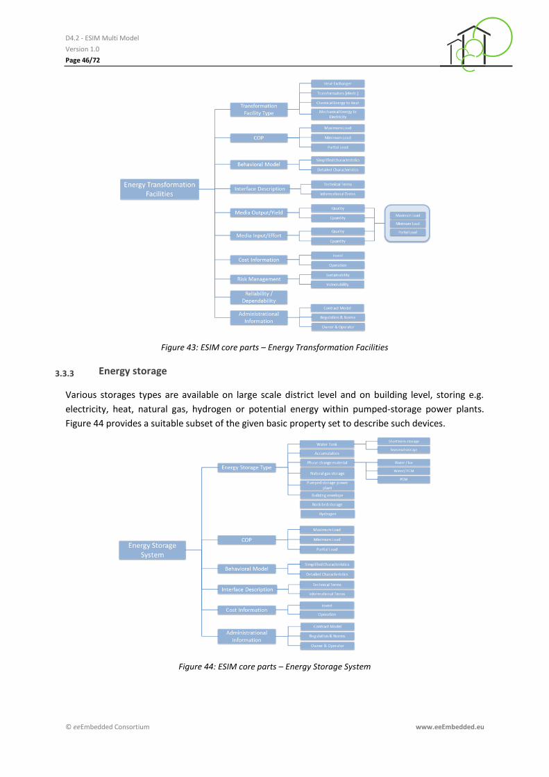
Energy transformation facilities
3.3.2
Closely connected with the public available access to an repository about energy source a unified
data repository is needed which provides technical terms for connecting the systems combined with
operational limits and restrictions by law. Figure 43 provides a subset of the introduced basic list of
property sets which will be used to describe energy transformation facilities like heat exchanger,
boiler, heat pumps and similar devices.
D4.2 - ESIM Multi Model
Version 1.0
Page 46/72
© eeEmbedded Consortium www.eeEmbedded.eu
Figure 43: ESIM core parts – Energy Transformation Facilities
Energy storage 3.3.3
Various storages types are available on large scale district level and on building level, storing e.g.
electricity, heat, natural gas, hydrogen or potential energy within pumped-storage power plants.
Figure 44 provides a suitable subset of the given basic property set to describe such devices.
Figure 44: ESIM core parts – Energy Storage System
D4.2 - ESIM Multi Model
Version 1.0
Page 47/72
© eeEmbedded Consortium www.eeEmbedded.eu
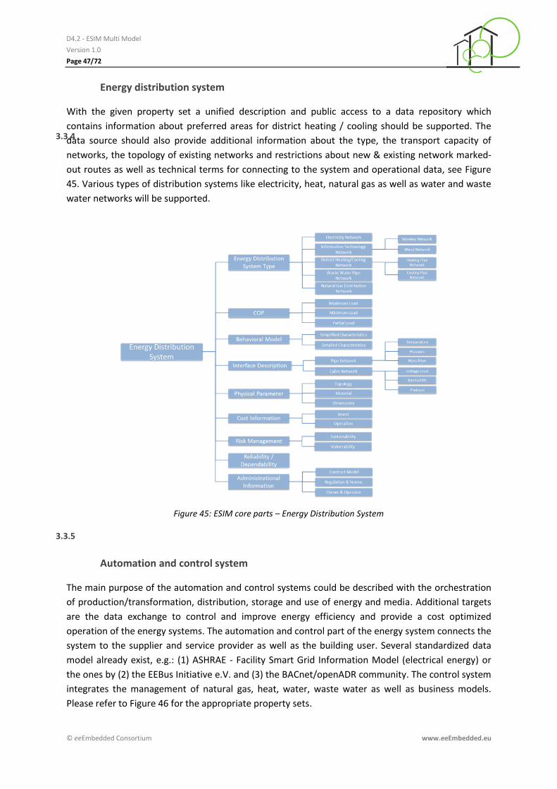
Energy distribution system
3.3.4
With the given property set a unified description and public access to a data repository which
contains information about preferred areas for district heating / cooling should be supported. The
data source should also provide additional information about the type, the transport capacity of
networks, the topology of existing networks and restrictions about new & existing network marked-
out routes as well as technical terms for connecting to the system and operational data, see Figure
45. Various types of distribution systems like electricity, heat, natural gas as well as water and waste
water networks will be supported.
Figure 45: ESIM core parts – Energy Distribution System
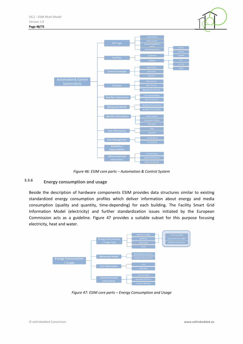
Automation and control system
3.3.5
The main purpose of the automation and control systems could be described with the orchestration
of production/transformation, distribution, storage and use of energy and media. Additional targets
are the data exchange to control and improve energy efficiency and provide a cost optimized
operation of the energy systems. The automation and control part of the energy system connects the
system to the supplier and service provider as well as the building user. Several standardized data
model already exist, e.g.: (1) ASHRAE - Facility Smart Grid Information Model (electrical energy) or
the ones by (2) the EEBus Initiative e.V. and (3) the BACnet/openADR community. The control system
integrates the management of natural gas, heat, water, waste water as well as business models.
Please refer to Figure 46 for the appropriate property sets.
D4.2 - ESIM Multi Model
Version 1.0
Page 48/72
© eeEmbedded Consortium www.eeEmbedded.eu
Figure 46: ESIM core parts – Automation & Control System
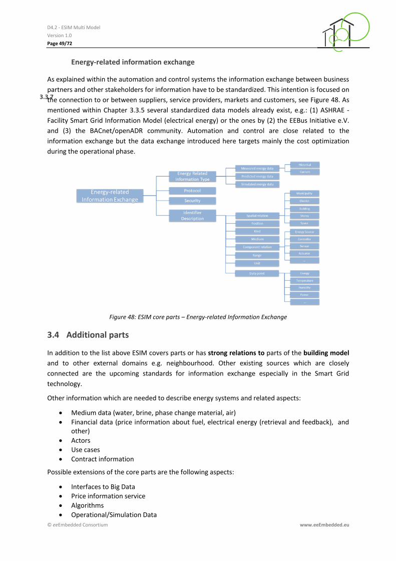
Energy consumption and usage 3.3.6
Beside the description of hardware components ESIM provides data structures similar to existing
standardized energy consumption profiles which deliver information about energy and media
consumption (quality and quantity, time-depending) for each building. The Facility Smart Grid
Information Model (electricity) and further standardization issues initiated by the European
Commission acts as a guideline. Figure 47 provides a suitable subset for this purpose focusing
electricity, heat and water.
Figure 47: ESIM core parts – Energy Consumption and Usage
D4.2 - ESIM Multi Model
Version 1.0
Page 49/72
© eeEmbedded Consortium www.eeEmbedded.eu
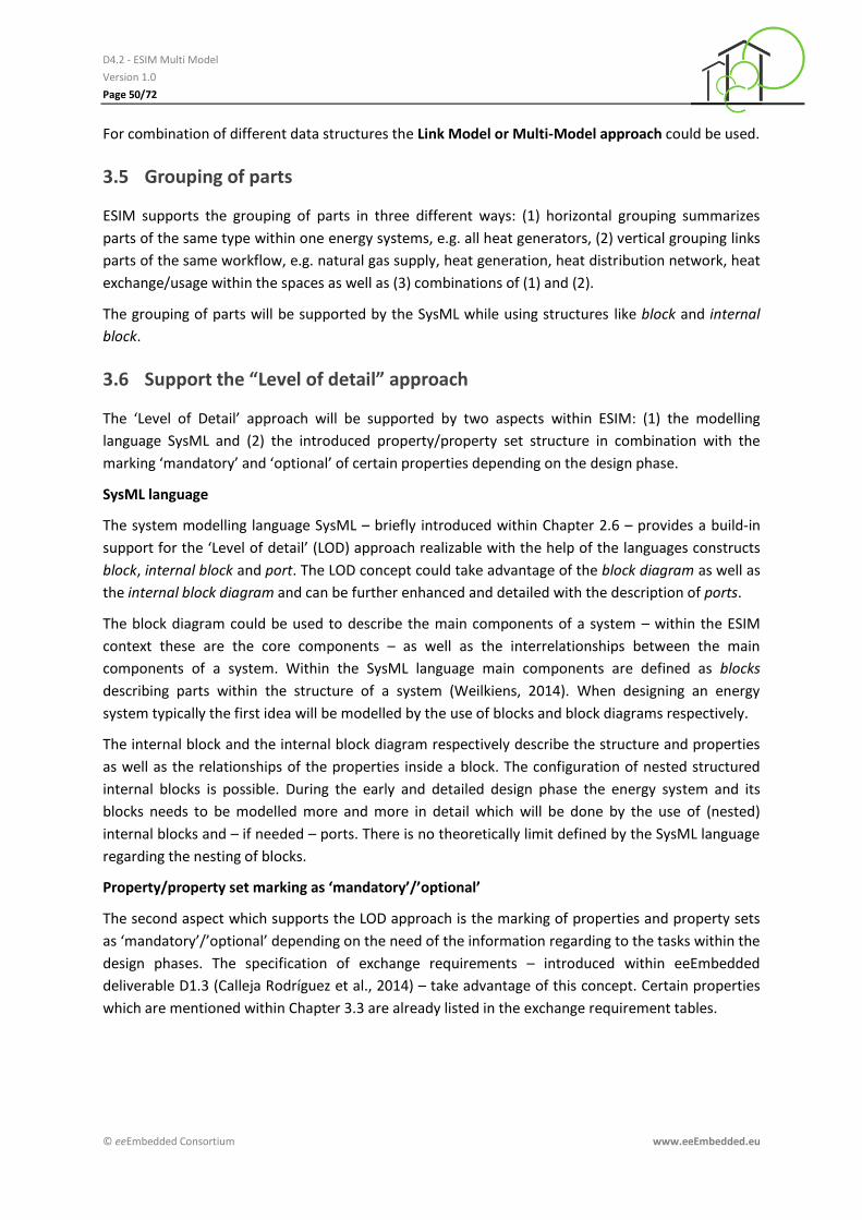
Energy-related information exchange
3.3.7
As explained within the automation and control systems the information exchange between business
partners and other stakeholders for information have to be standardized. This intention is focused on
the connection to or between suppliers, service providers, markets and customers, see Figure 48. As
mentioned within Chapter 3.3.5 several standardized data models already exist, e.g.: (1) ASHRAE -
Facility Smart Grid Information Model (electrical energy) or the ones by (2) the EEBus Initiative e.V.
and (3) the BACnet/openADR community. Automation and control are close related to the
information exchange but the data exchange introduced here targets mainly the cost optimization
during the operational phase.
Figure 48: ESIM core parts – Energy-related Information Exchange
3.4 Additional parts
In addition to the list above ESIM covers parts or has strong relations to parts of the building model
and to other external domains e.g. neighbourhood. Other existing sources which are closely
connected are the upcoming standards for information exchange especially in the Smart Grid
technology.
Other information which are needed to describe energy systems and related aspects:
Medium data (water, brine, phase change material, air)
Financial data (price information about fuel, electrical energy (retrieval and feedback), and other)
Actors
Use cases
Contract information
Possible extensions of the core parts are the following aspects:
Interfaces to Big Data
Price information service
Algorithms
Operational/Simulation Data
D4.2 - ESIM Multi Model
Version 1.0
Page 50/72
© eeEmbedded Consortium www.eeEmbedded.eu
For combination of different data structures the Link Model or Multi-Model approach could be used.
3.5 Grouping of parts
ESIM supports the grouping of parts in three different ways: (1) horizontal grouping summarizes
parts of the same type within one energy systems, e.g. all heat generators, (2) vertical grouping links
parts of the same workflow, e.g. natural gas supply, heat generation, heat distribution network, heat
exchange/usage within the spaces as well as (3) combinations of (1) and (2).
The grouping of parts will be supported by the SysML while using structures like block and internal
block.
3.6 Support the “Level of detail” approach
The ‘Level of Detail’ approach will be supported by two aspects within ESIM: (1) the modelling
language SysML and (2) the introduced property/property set structure in combination with the
marking ‘mandatory’ and ‘optional’ of certain properties depending on the design phase.
SysML language
The system modelling language SysML – briefly introduced within Chapter 2.6 – provides a build-in
support for the ‘Level of detail’ (LOD) approach realizable with the help of the languages constructs
block, internal block and port. The LOD concept could take advantage of the block diagram as well as
the internal block diagram and can be further enhanced and detailed with the description of ports.
The block diagram could be used to describe the main components of a system – within the ESIM
context these are the core components – as well as the interrelationships between the main
components of a system. Within the SysML language main components are defined as blocks
describing parts within the structure of a system (Weilkiens, 2014). When designing an energy
system typically the first idea will be modelled by the use of blocks and block diagrams respectively.
The internal block and the internal block diagram respectively describe the structure and properties
as well as the relationships of the properties inside a block. The configuration of nested structured
internal blocks is possible. During the early and detailed design phase the energy system and its
blocks needs to be modelled more and more in detail which will be done by the use of (nested)
internal blocks and – if needed – ports. There is no theoretically limit defined by the SysML language
regarding the nesting of blocks.
Property/property set marking as ‘mandatory’/’optional’
The second aspect which supports the LOD approach is the marking of properties and property sets
as ‘mandatory’/’optional’ depending on the need of the information regarding to the tasks within the
design phases. The specification of exchange requirements – introduced within eeEmbedded
deliverable D1.3 (Calleja Rodríguez et al., 2014) – take advantage of this concept. Certain properties
which are mentioned within Chapter 3.3 are already listed in the exchange requirement tables.

D4.2 - ESIM Multi Model
Version 1.0
Page 51/72
© eeEmbedded Consortium www.eeEmbedded.eu
3.7 Relation to templates for fast semi-automatic detailing
The design of energy systems will be a successor of the template approach within the eeEmbedded
framework too to speed up the design process. Like other working steps the description of energy
systems could be supported by various types of templates.
Figure 49: eeEmbedded Template Library
The approach of structuring into systems, subsystems and components provides the usage of simple
and complex templates which are described within the eeEmbedded deliverables D1.4 (Solvik, 2014)
und D2.2 (Zellner et al., 2015). For management and distribution purposes templates will be
organized within temple libraries, see Figure 49.
Figure 50: Cross-domain Template – Standard Office Room
The usage of complex templates in a cross-domain-orientated manner provides the ability of
combining pre-defined energy systems with pre-defined buildings or spaces, see (Guruz et al., 2015).
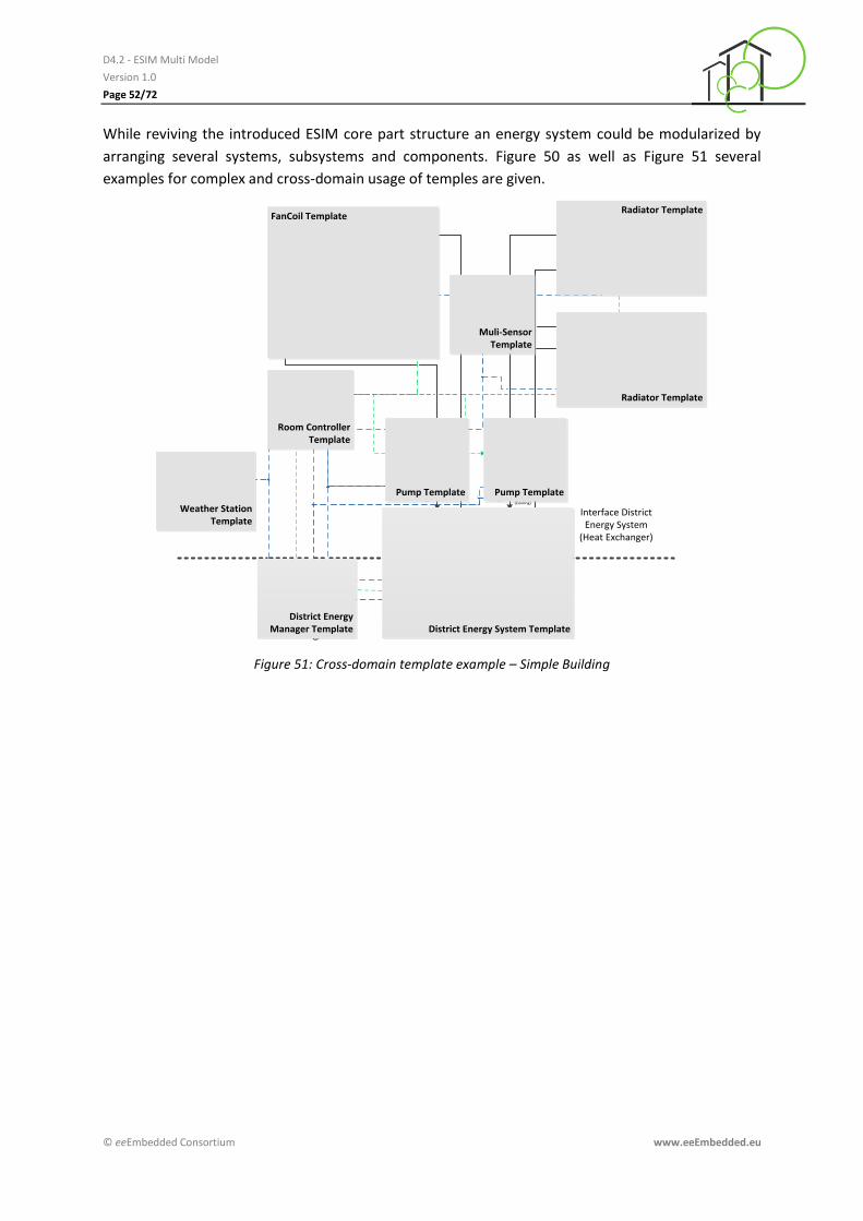
D4.2 - ESIM Multi Model
Version 1.0
Page 52/72
© eeEmbedded Consortium www.eeEmbedded.eu
While reviving the introduced ESIM core part structure an energy system could be modularized by
arranging several systems, subsystems and components. Figure 50 as well as Figure 51 several
examples for complex and cross-domain usage of temples are given.
Pump
Fan-CoilRH
T
Q
T
Q
Pump
Q
Fan-Coil Controller
Interface District Energy System
(Heat Exchanger)
District Energy Manager
Radiator
Radiator
Radiator Thermostat
Radiator Thermostat
WW
District Energy System
T
WS
Weather Station (Physical or Service)
3x Multi Sensor
Energy Meter (Cooling)
Energy Meter (Heating)
T
T
T
CO2
T T
Room Controller Template
District Energy Manager Template District Energy System Template
Weather Station Template
Pump Template Pump Template
FanCoil Template
Radiator Template
Radiator Template
Muli-Sensor Template
Figure 51: Cross-domain template example – Simple Building
D4.2 - ESIM Multi Model
Version 1.0
Page 53/72
© eeEmbedded Consortium www.eeEmbedded.eu
4 ESIM Specification and Conceptualization
4.1 Ontology Basics and Modelling Methodology
The following chapter presents the modelling methodology of the ESIM ontology. Initially a rough
introduction of ontology basics is given and the advantage of an ontology approach is pointed out.
Ontologies are becoming increasingly important in fields such as knowledge management,
information integration, cooperative information systems and information retrieval. The goal of
ontology is to share common understanding of the structure of information among people or
software applications in order to enable the reuse of knowledge in a specific field. Ontology are often
seen as a normative model, which represents concepts of a knowledge domain and the relationship
between the concepts (Staab et al., 2009). Staab et al. (2009) defines an ontology as follows: “An
ontology is a formal, explicit specification of a shared conceptualization.” In general ontologies can
be used for domain description, data modelling, data integration and linked data as well as inference
and reasoning.
Ontologies can be basically classified in many way using criteria such as the degree of abstraction
(lightweight or heavyweight) and field of application (general or domain specific). However, there
exist the four main classes of ontologies, namely, domain ontology, upper ontology interface
ontology and process ontology. Domain ontologies represent concepts and relations relevant to a
particular topic or area of interest. The construction domain and their different disciplines form a
typical example for domain ontologies. The ESIM ontology covering vocabulary of the urban and
building energy system including the automation and control systems can be assigned to this
category. Interface ontologies cover concepts and relations relevant to the juncture of two
disciplines. The Link Ontology to be developed in T5.5 is a typical representative of interface
ontology. It connects the domain ontologies (BIM, ESIM and NIM) to the eeeBIM ontology.
Coming to the technical background an ontology requires a standard language to express domain
knowledge. Therefore, different ontology languages such as DAML+OIL (Connolly, Dan et al., 2001) –
a successor to DAML (DARPA Agent Markup Language) (DARPA, 2006) and OIL (Ontology Inference
Layer) (Fensel et al., 2001) that combines features of both, has been used in the past. Currently the
World Wide Web Consortium (W3C) offers a large palette of techniques and languages to describe
and define different forms of vocabularies or ontologies respectively in a standardized format. These
include Resource Description Framework (RDF) and RDF Schemas, Simple Knowledge Organization
System (SKOS), Web Ontology Language (OWL), and the Rule Interchange Format (RIF). The choice
among these different technologies depends on the complexity and rigor required by a specific
application. The ontology modelling methodology presented in the following is independent from a
specific ontology language. Before implementing ontologies in a specific ontology language the
requirements (intentions of use, context, type of ontology, etc.), the vocabulary (main terms) and a
proper conceptualization has to be elaborated.
The Figure 52 (left) presents the ontology modelling methodology to be performed to elaborate the
ESIM ontology. The methodology is divided into five main steps, namely (1) requirement analysis, (2)
vocabulary definition, (3) ontology conceptualization, (4) ontology search, selection and reuse, as
well as (5) ontology implementation. The following sections the focus is on the first three steps of the

D4.2 - ESIM Multi Model
Version 1.0
Page 54/72
© eeEmbedded Consortium www.eeEmbedded.eu
overall methodology (Figure 52, right). However, an overview on the future work, mainly performed
in WP5, is given in Chapter 4.5.
Figure 52: ESIM Ontology – Modelling Methodology
4.2 Requirements and vocabulary definition
Ontology requirements specification refers to the activity of collecting the requirements that the
ontology should fulfil and possibly reach through a consensus process. Hence the requirement and
vocabulary definition forms an important and critical step in modelling ontologies where
fundamental decisions have to be taken already in early stages of the modelling process. Questions
like (1) purpose, (2) scope, (3) implementation language, and (4) intended end-user and use of the
ontology have to be answered (Suárez-Figueroa, 2008).
The ESIM ontology is intended to be a domain specific ontology that providing a vocabulary of the
urban and building energy system including the automation and control systems. Further functional,
structural and physical aspects of the systems as well as operational data are in the scope. A detailed
description of the ESIM scope was given in chapter 2.6.
Based on the purpose, scope and the intentions the vocabularies can be extracted. The World Wide
Web Consortium defines vocabularies as concepts and relationships (also referred to as “terms”)
used to describe and represent an area of concern. Concepts and relationships are also referred to as
so called “terms”. Vocabularies are used to classify the terms that can be used in a particular
application, characterize possible relationships, and define possible constraints on using those terms.
In practice, vocabularies can be very complex with several thousands of terms or very simple
describing one or two concepts only (W3C, 2015a).
The informational demand identified in chapter 1.4 and the Exchange Requirements tables specified
in D1.3 (Calleja Rodríguez and Guruz, 2014) served as basis to define a seed vocabulary. There exists
a strong relationship or intersection respectively among the ESIM vocabulary and the Exchange

D4.2 - ESIM Multi Model
Version 1.0
Page 55/72
© eeEmbedded Consortium www.eeEmbedded.eu
Requirement (ER) tables. The ER Tables are used to specify information to be exchanged between
actors of the different domains during the eeE design process. Hence the information covering the
scope of the ESIM ontology are potential concepts and their relationships among another.
The ESIM vocabulary divided into seven main concepts, namely energy sources, energy
transformation facilities, energy storage system, energy distribution system, automation &control
system, energy consumption & usage as well as energy related-information exchange. These
concepts represent the ESIM core parts defined in chapter 3.3. The visualization of the ESIM
vocabulary and the related terms for each core part can be seen in chapter 3.3.
4.3 Ontology conceptualization
After extracting a seed ESIM vocabulary (concepts and relationships), see visualizations of the ESIM
core parts in Chapter 3.3, the ESIM conceptualization tables have been worked out. This deliverable
only considers the first draft of the ontology conceptualization. The initial modelling draft will be
further detailed in the ongoing work. The intention of this ontology modelling steps is to organize
and structure the information (terms, data, knowledge, etc.) elaborated in the previous step into
meaningful models on knowledge level. This includes identifying main concepts and their
relationships among each other.
Table 2: Structure of the ESIM conceptualization tables
The ESIM conceptualization tables provide a formal representation of concepts and relationships
used to describe and represent the ESIM related vocabulary. The tables have been structured as
follows (see Table 2):
The first column names the concept. Further the relationships to sub-concepts (is) and to attributes (has) is presented. The hierarchy level of sub-concepts is not restricted.
The second column (“Description”) describes the concept or the relationship respectively.
The third column (“Type of Data”) represents the type of data. It can be either descriptive (e.g. STRING), or numeric (e.g. REAL or DATE).
The fourth column (“Unit”) shows the corresponding unit. Units are just applicable for numerical data types.
The fifth column (“Reference To Concept”) references to the corresponding ESIM concept, where it is more detailed.
The sixth column lists references to standards, data models or reused ontologies.
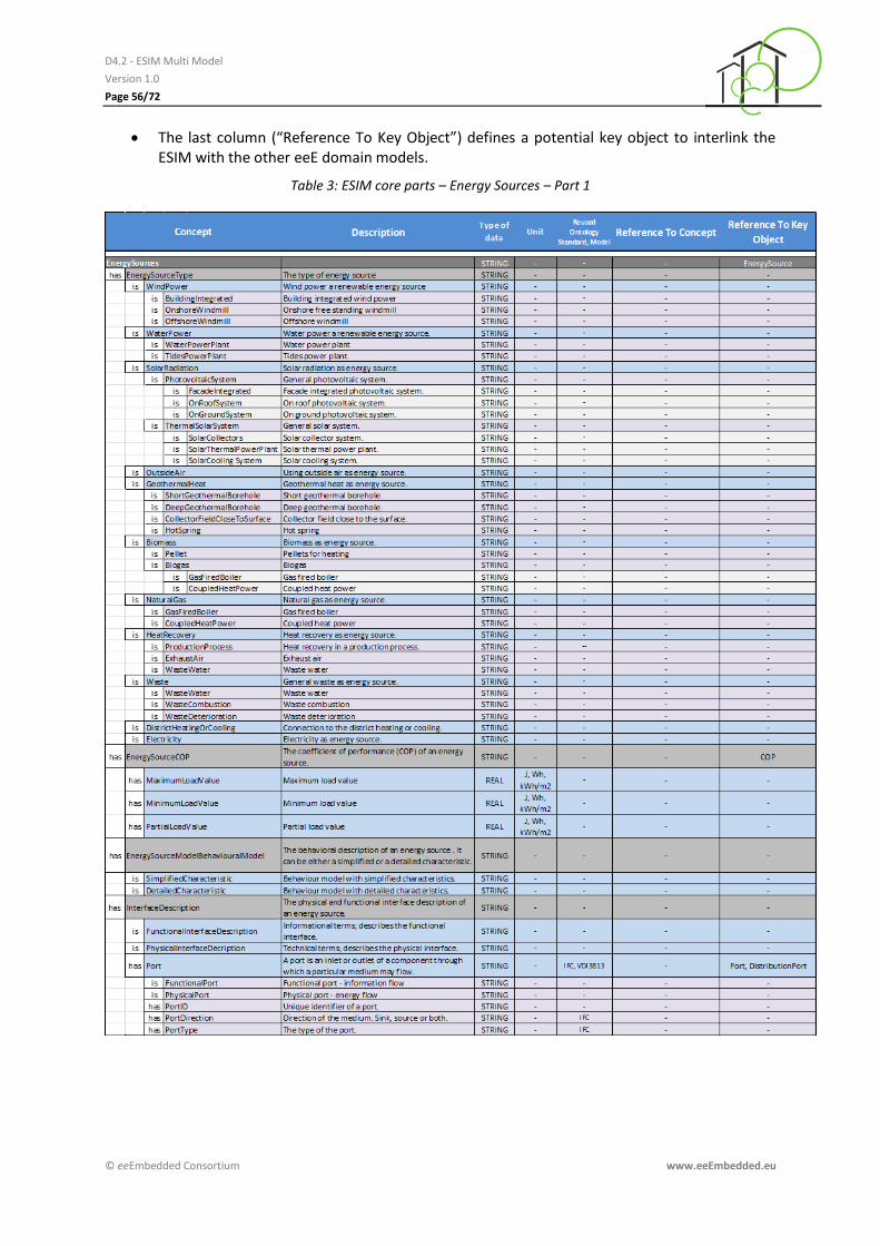
D4.2 - ESIM Multi Model
Version 1.0
Page 56/72
© eeEmbedded Consortium www.eeEmbedded.eu
The last column (“Reference To Key Object”) defines a potential key object to interlink the ESIM with the other eeE domain models.
Table 3: ESIM core parts – Energy Sources – Part 1
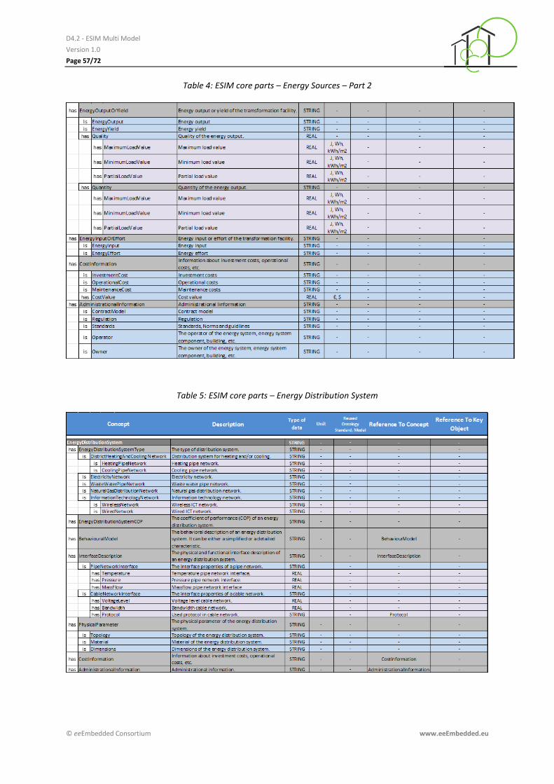
D4.2 - ESIM Multi Model
Version 1.0
Page 57/72
© eeEmbedded Consortium www.eeEmbedded.eu
Table 4: ESIM core parts – Energy Sources – Part 2
Table 5: ESIM core parts – Energy Distribution System
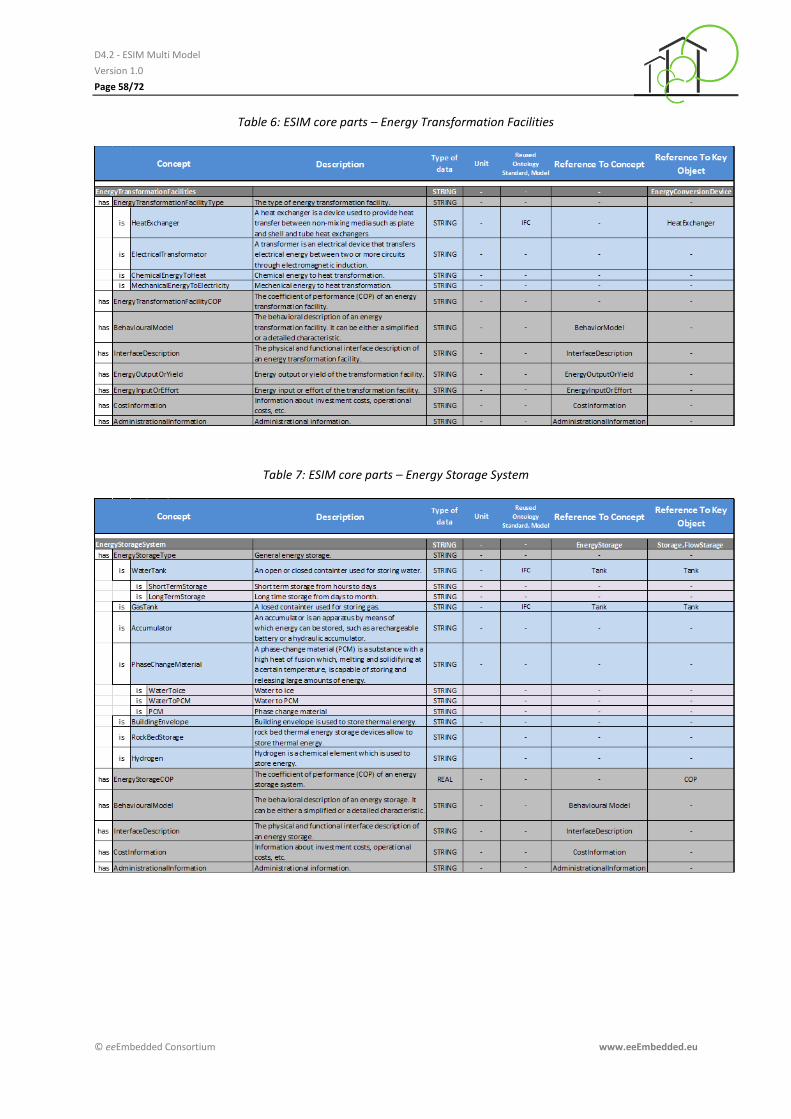
D4.2 - ESIM Multi Model
Version 1.0
Page 58/72
© eeEmbedded Consortium www.eeEmbedded.eu
Table 6: ESIM core parts – Energy Transformation Facilities
Table 7: ESIM core parts – Energy Storage System
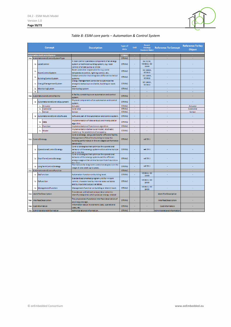
D4.2 - ESIM Multi Model
Version 1.0
Page 59/72
© eeEmbedded Consortium www.eeEmbedded.eu
Table 8: ESIM core parts – Automation & Control System
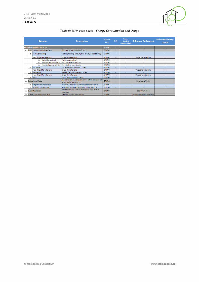
D4.2 - ESIM Multi Model
Version 1.0
Page 60/72
© eeEmbedded Consortium www.eeEmbedded.eu
Table 9: ESIM core parts – Energy Consumption and Usage

D4.2 - ESIM Multi Model
Version 1.0
Page 61/72
© eeEmbedded Consortium www.eeEmbedded.eu
Table 10: ESIM core parts – Energy-related Data
4.4 Ontology Search and Selection
After elaborating an initial modelling draft of the ESIM ontology the search and selection of already
existing ontologies should be performed. An appropriate reusable ontology and vocabulary have to
be able to represent all the required data. The search is an intensive task due to the shear amount of
existing ontologies. Unfortunately ontology libraries or catalogues offer possibilities to ease this
challenge.
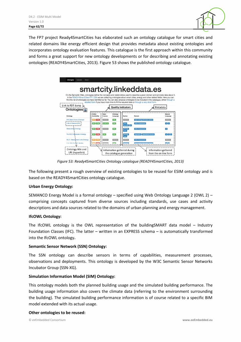
D4.2 - ESIM Multi Model
Version 1.0
Page 62/72
© eeEmbedded Consortium www.eeEmbedded.eu
The FP7 project Ready4SmartCities has elaborated such an ontology catalogue for smart cities and
related domains like energy efficient design that provides metadata about existing ontologies and
incorporates ontology evaluation features. This catalogue is the first approach within this community
and forms a great support for new ontology developments or for describing and annotating existing
ontologies (READY4SmartCities, 2013). Figure 53 shows the published ontology catalogue.
Figure 53: Ready4SmartCities Ontology catalogue (READY4SmartCities, 2013)
The following present a rough overview of existing ontologies to be reused for ESIM ontology and is
based on the READY4SmartCities ontology catalogue.
Urban Energy Ontology:
SEMANCO Energy Model is a formal ontology – specified using Web Ontology Language 2 (OWL 2) –
comprising concepts captured from diverse sources including standards, use cases and activity
descriptions and data sources related to the domains of urban planning and energy management.
IfcOWL Ontology:
The IfcOWL ontology is the OWL representation of the buildingSMART data model – Industry
Foundation Classes (IFC). The latter – written in an EXPRESS schema – is automatically transformed
into the IfcOWL ontology.
Semantic Sensor Network (SSN) Ontology:
The SSN ontology can describe sensors in terms of capabilities, measurement processes,
observations and deployments. This ontology is developed by the W3C Semantic Sensor Networks
Incubator Group (SSN-XG).
Simulation Information Model (SIM) Ontology:
This ontology models both the planned building usage and the simulated building performance. The
building usage information also covers the climate data (referring to the environment surrounding
the building). The simulated building performance information is of course related to a specific BIM
model extended with its actual usage.
Other ontologies to be reused:
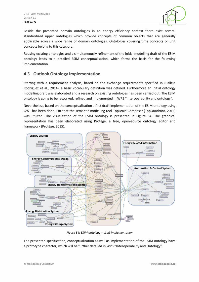
D4.2 - ESIM Multi Model
Version 1.0
Page 63/72
© eeEmbedded Consortium www.eeEmbedded.eu
Beside the presented domain ontologies in an energy efficiency context there exist several
standardized upper ontologies which provide concepts of common objects that are generally
applicable across a wide range of domain ontologies. Ontologies covering time concepts or unit
concepts belong to this category.
Reusing existing ontologies and a simultaneously refinement of the initial modelling draft of the ESIM
ontology leads to a detailed ESIM conceptualisation, which forms the basis for the following
implementation.
4.5 Outlook Ontology Implementation
Starting with a requirement analysis, based on the exchange requirements specified in (Calleja
Rodríguez et al., 2014), a basic vocabulary definition was defined. Furthermore an initial ontology
modelling draft was elaborated and a research on existing ontologies has been carried out. The ESIM
ontology is going to be reworked, refined and implemented in WP5 “Interoperability and ontology”.
Nevertheless, based on the conceptualization a first draft implementation of the ESIM ontology using
OWL has been done. For that the semantic modelling tool TopBraid Composer (TopQuadrant, 2015)
was utilized. The visualization of the ESIM ontology is presented in Figure 54. The graphical
representation has been elaborated using Protégé, a free, open-source ontology editor and
framework (Protégé, 2015).
Figure 54: ESIM ontology – draft implementation
The presented specification, conceptualization as well as implementation of the ESIM ontology have
a prototype character, which will be further detailed in WP5 “Interoperability and Ontology”.
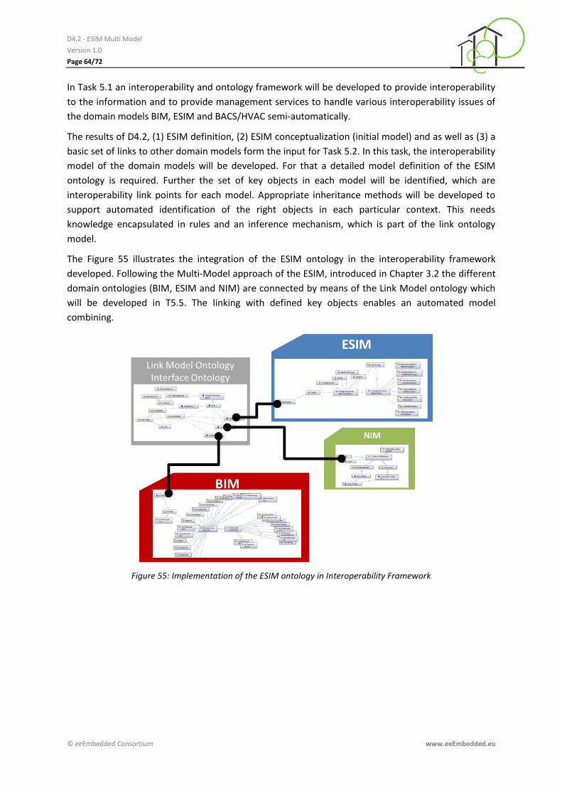
D4.2 - ESIM Multi Model
Version 1.0
Page 64/72
© eeEmbedded Consortium www.eeEmbedded.eu
In Task 5.1 an interoperability and ontology framework will be developed to provide interoperability
to the information and to provide management services to handle various interoperability issues of
the domain models BIM, ESIM and BACS/HVAC semi-automatically.
The results of D4.2, (1) ESIM definition, (2) ESIM conceptualization (initial model) and as well as (3) a
basic set of links to other domain models form the input for Task 5.2. In this task, the interoperability
model of the domain models will be developed. For that a detailed model definition of the ESIM
ontology is required. Further the set of key objects in each model will be identified, which are
interoperability link points for each model. Appropriate inheritance methods will be developed to
support automated identification of the right objects in each particular context. This needs
knowledge encapsulated in rules and an inference mechanism, which is part of the link ontology
model.
The Figure 55 illustrates the integration of the ESIM ontology in the interoperability framework
developed. Following the Multi-Model approach of the ESIM, introduced in Chapter 3.2 the different
domain ontologies (BIM, ESIM and NIM) are connected by means of the Link Model ontology which
will be developed in T5.5. The linking with defined key objects enables an automated model
combining.
Figure 55: Implementation of the ESIM ontology in Interoperability Framework

D4.2 - ESIM Multi Model
Version 1.0
Page 65/72
© eeEmbedded Consortium www.eeEmbedded.eu
5 Software applications
5.1 Editors with GUI
Related to the preferred modelling language SysML there are different editors available on open
source basis, as freeware and as commercial solution. These editors provide a GUI and comfortable
workflow including the integrated access to model repositories. Figure 56 provides a screenshot of
the commercial product “Enterprise Architect”.
Open source
• PolarSys “Papyrus SysML Solution” (PolarSys, 2015) • PolarSys “TOPCASED” (PolarSys, 2015a) Commercial
• PTC Inc. “PTC Integrity Modeler” (PTC, 2015) • Sparx Systems Ltd. “Enterprise Architect®” (Sparx, 2015) • Microsoft “Visio®” (Microsoft, 2015) templates • Altova GmbH “UModel®” or “MissionKit®” (Altova, 2015)
Figure 56: Screenshot of the software application “Enterprise Architect”
5.2 Interactions and services
In Chapter 4 the specification and conceptualization ESIM ontology (ESIM data schema) on class level
was presented. The follow chapter describes an overview on possible interactions and service on
ESIM ontology on instance level (ESIM data models).
5.3 Converter services
Despite a specified ESIM schema level certain transformation of ESIM date models (instance level)
are necessary. Several software applications in the eeE design process have to deal with ESIM

D4.2 - ESIM Multi Model
Version 1.0
Page 66/72
© eeEmbedded Consortium www.eeEmbedded.eu
instances. There exists no standardized exchange format which is supported by each application.
Therefore a need of a converter service arises. The following transformations/conversions
possibilities have to be provided:
(1) XMI2XMLESIM using XSLT-script
(2) XMI2RDF/XMLESIM using XSLT-script or Java (Apache Jena)
(3) XMLESIM2XMLIFC using XSLT-script or Java (JSDAI)
(4) XMLESIM2SPFIFC using XSLT-script or Java
Using “Enterprise Architect” (EA) and the System Modeling Language (SysML) for energy system
design results an ESIM data model as XML Metadata Interchange (XMI). XMI is a standard for
exchanging metadata information via Extensible Markup Language (XML). In order to use these
results the XMI export must be transformed to an ESIM schema. The transformation can be either
XMI2XMLESIM or XMI2RDF/XMLESIM. For the interoperability and ontology framework, developed in
WP5, the transformation XMI2RDF/XMLESIM is required to instantiate the ESIM domain ontology. In
general Authoring and simulation tools in the eeE design process already support the standardized
exchange format IFC2x3 and/or IFC4 (tool developer adopt their interfaces currently). Therefore, the
conversion from XMLESIM2XMLIFC or XMLESIM2SPFIFC is useful to establish the ESIM developments in
existing software tools.
Figure 57: ESIM Converter Services
It is planned to implement the transformations XMI2XMLESIM and XMI2RDF/XMLESIM to provide design
data to perform energy and thermal simulation using TRNSYS-TUD. The transformation is optional.
5.4 Filter and query services
Filter and query services can be used to retrieve a subset of the information space provided by ESIM
data models. Using queries languages is a widely spread method to retrieve information from data
bases or data repositories. Representing the ESIM ontology in RDF (Resource Description Framework)
or OWL (Web Ontology Language) respectively, the advantages of RDF can be used. RDF is a directed,
labelled graph data format for representing information. Hence filtering and querying can be done by
using SPARQL queries which operate on the ESIM ontology stored on a RDF triplestore (W3C, 2015).
Using SPARQL queries allows to access data of distributed ESIM data models. Retrieving information
from more than one ESIM data model is necessary to access information about existing energy
D4.2 - ESIM Multi Model
Version 1.0
Page 67/72
© eeEmbedded Consortium www.eeEmbedded.eu
systems in the neighbourhood or interface to industrial energy provider. A question to be answered
in the planning of a district energy system could be: What kind heat energy sources are available and
which provide more than 0.5 MWh.
5.5 Simulation mapper services
A specific ESIM instance provides behavioural descriptions of the energy systems, sub-systems and
components as well as the behaviour of the automation and control system, sub-systems and
components. The aggregation of these behavioural descriptions to an integrated simulation model is
one of the functionalities provided by the simulation mapper service. Further the ESIM may supply
access to set up the simulation input data automatically. The corresponding mapping and
aggregation methods to transformation of information models (IFC, ESIM) to appropriated simulation
models (physical models) will be developed in WP6 “Cloud-based Multi-Physics Simulation and KPI
Quantification”.
5.6 Template management services
In Chapter 3.5 the strong relation of the ESIM and the generic template approach for fast semi-
automatic detailing was pointed out. For that a need of certain functionalities regarding ESIM and
ESIM template arise. Template management services provide among another services to (1) set-up
and configuration services, (2) aggregation services, and (3) transformation and integrations services.
The template management services are no ESIM specific developments. These services and
interactions regarding templates are needed across different domains and applications.
D4.2 - ESIM Multi Model
Version 1.0
Page 68/72
© eeEmbedded Consortium www.eeEmbedded.eu
6 Conclusions and outlook
The analysis of current design steps involved in the creation of an energy system shows the
informational gaps and the need for a unified description of energy systems, see Chapter 1. The
identification of core parts within an energy system in combination with a cross-domain-orientated
set off properties should be a starting point for a unified modelling of energy systems.
Systems Engineering with its related modelling languages UML and SysML is a popular approach for
the description of energy systems, see Chapter 2. A wide range of standards are available or
currently under construction initiated and elaborated by several domains in a highly dynamic
manner. All results described within this document have to be interpreted as a snapshot of the
current cross-domain-driven movement to a formalization of system description. The same is valid
for all working tasks within the design and operation phase of buildings and energy systems, see
Chapter 3.
In Chapter 4 the formal specification and conceptualization of the ESIM ontology were presented.
The introduced ESIM ontology methodology can be divided into five main steps, namely (1)
requirement analysis, (2) vocabulary definition, (3) ontology conceptualization, (4) ontology search,
selection and reuse, as well as (5) ontology implementation. Starting with the requirement analysis
and the vocabulary definition the scope and intention of the ESIM ontology were specified. Based on
the informational demand and the ESIM core part definition, explained in Chapter 3, the
conceptualization of the ESIM core parts were elaborated. The results of the first three steps were
presented in detail. Further an extended outlook of the remaining development steps was given.
These form the basis for WP5 “Interoperability and Ontology” and will be detailed in the following
work.
ESIM related software applications and an overview on possible interactions and services were
introduced in Chapter 5. Modelling environments supporting system and requirement engineering
approach by using System Modelling Language (SysML) were investigated and presented. Such
modelling environments, open source as well as commercial solutions, allow the design of energy-
efficient embedded energy system following a system-oriented approach. Further the need of
different services for ESIM on knowledge level was pointed out and the functional requirements and
intention of the following services were explained: (1) converter services, (2) filter and query
services, (3) simulation mapper services as well as (4) template management services.
Currently experts of several different domains such as ‘Smart City’, ‘Smart Grid’, ‘Smart Home’, BIM
and other are working intensively on the standardized modelling of several parts of energy system as
well as the more formulized description of building and the neighbourhood. Within this topic a highly
dynamic development is recognisable resulting in completely new or re-worked standards and ‘best
practice’ guidelines with high impact on the introduced approach of ESIM, therefor this deliverable
has to be understood as a starting point. The work on ESIM - especially the implementation - is an
ongoing task while considering actual developments within both, the project and the external
standardization activities. Especially within WP5 the ontology and the multi-model approach will be
elaborated more in detail. ESIM will be integrated as much as possible within the eeEmbedded
framework following the systems engineering approach.

D4.2 - ESIM Multi Model
Version 1.0
Page 69/72
© eeEmbedded Consortium www.eeEmbedded.eu
D4.2 - ESIM Multi Model
Version 1.0
Page 70/72
© eeEmbedded Consortium www.eeEmbedded.eu
References
Altova GmbH & Altova Inc., (2015). Altova MissionKit®. URL: http://www.altova.com/missionkit.html
[Stand 2015-07-28].
ASHRAE SPC201, ASHRAE (2012). Facility Smart Grid Information Model: Advisory Public Review Draft
[Stand 2014-10-23].
Calleja Rodríguez, G. and Guruz, R. (2014); eeEmbedded D1.3: Interoperability and collaboration
requirements, © eeEmbedded Consortium, Brussels.
CEN-CENELEC-ETSI Smart Grid Coordination Group (2014). SG-CG/M490/K_ SGAM usage and
examples: SGAM User Manual - Applying, testing & refining the Smart Grid Architecture
Model (SGAM). Version 3.0.
Connolly, Dan et al., (2001). DAML+OIL Reference Description. W3C Note, 18 December 2001.
http://www.w3.org/TR/daml+oil-reference.
DARPA, (2006). The DARPA Agent Markup Language Homepage. http://www.daml.org/.
Deutsches Institut für Normung e. V. (2011) DIN EN 15232 - Energy performance of buildings –
Impact of Building Automation, Controls and Building Management. German version FprEN
15232:2011.
Deutsches Institut für Normung e. V. (2005) DIN EN ISO 16484 - Building automation and control
systems (BACS) -- Part 3: Functions.
Deutsches Institut für Normung e. V. & DKE Deutsche Kommission Elektrotechnik Elektronik
Informationstechnik im DIN und VDE (2015). The German Standardization Roadmap – Smart
City: Version 1.1. URL:
http://www.din.de/sixcms_upload/media/2896/Normungsroadmap_SmartCity_EN_2105.pdf
Distributed Management Task Force Inc. (DTMF) (2015). Common Information Model (CIM) Schema:
Version 2.44.1. URL: http://dmtf.org/standards/cim/cim_schema_v2441 [Stand 2015-07-30].
Fensel, Dieter et al., (2001). OIL: An Ontology Infrastructure for the Semantic Web. IEEE Intelligent
Systems, 16(2):38–45, March 2001.
FINESCE consortium (2015). Project FINESCE (Future INtErnet Smart Utility ServiCEs). URL:
http://www.finesce.eu/ [Stand 2015-06-25].
FINSENY consortium (2011). FINSENY | Future Internet for Smart Energy. URL: http://www.fi-ppp-
finseny.eu/ [Stand 2015-06-25].
Friedenthal, Sanford, Moore, Alan & Steiner, Rick (2008). A practical guide to SysML: Systems Model
Language. Burlington, Mass.: Elsevier/Morgan Kaufmann.
Geißler, M.C., Guruz, R., van Woudenberg, W. (2014); eeEmbedded Deliverable D1.1: Vision and
requirements for a KPI-based holistic multi-disciplinary design, © eeEmbedded Consortium,
Brussels.
D4.2 - ESIM Multi Model
Version 1.0
Page 71/72
© eeEmbedded Consortium www.eeEmbedded.eu
Gnüchtel, S., Kaiser, J., Pruvost, H., Stenzel, P., Grille, T., Schär, R. (2015); eeEmbedded D3.1:
Stochastic, risk and vulnerability models and control strategies, © eeEmbedded Consortium,
Brussels.
Guruz, R., Calleja Rodríguez, G. & Geißler, M.-C. (2015): eeEmbedded Deliverable D2.3: Holistic KPI
based design methodology © eeEmbedded Consortium, Brussels.
International District Energy Association (2015). Community Energy: Planning, Development &
Delivery - US Version. Westborough. URL: http://districtenergy.org/community-energy-
planning-development-and-delivery [Stand 2015-06-25].
International District Energy Association (2015). Community Energy Development Guide - Canada -
District Energy. URL: http://districtenergy.org/community-energy-development-guide-
canada [Stand 2015-06-25].
International Organization for Standardization (2015). ISO 16757-1:2015 (E) - Data structures for
electronic product catalogues for building services - Part 1: Concepts, architecture and
model. Genf: ISO.
International Organization for Standardization (2008) ISO/IEC 15288 Description of the processes of
the systems life cycle. Genf: ISO.
King, Michael (2012). Community Energy: Planning, Development and Delivery. URL:
http://www.districtenergy.org/assets/pdfs/Community-Energy-Dev-Guide-US-
version/USCommunityEnergyGuidehi.pdf [Stand 2015-06-25].
Microsoft Corporation (2015). Microsoft Visio | Professional Flow Chart & Diagram Software. URL:
https://products.office.com/en-gb/Visio/flowchart-software [Stand 2015-07-28].
Mosch, M. & Kaiser J. (2015); eeEmbedded D4.1: BIM Multi-Model, Multi-Physics Models and
Management Methods, © eeEmbedded Consortium, Brussels.
Neumann, Scott (2010). IEC CIM, Enterprise Architect, Profiles and CIMTool: The power of
integration. URL: https://www.oasis-open.org/committees/download.php/
36238/IEC%20CIM%20-%20%20Profiles%20and%20CIMTool.pdf [Stand 2015-08-26].
Object Management Group® (OMG®) (2012). OMG Systems Modeling Language (OMG SysML™) -
Version 1.3. URL: http://www.omg.org/spec/SysML/1.3/PDF.
Object Management Group® (OMG®) (2015). OMG's MetaObject Facility (MOF) Core Specification -
Version 2.5. URL: http://www.omg.org/mof/ [Stand 2015-08-17].
Object Management Group® (OMG®) (2015). OMG Systems Modeling Language (OMG SysML™) -
Version 1.4: (Beta Specification of the SysML 1.4 RTF, without change bars). URL:
http://www.omg.org/spec/SysML/1.4/Beta/PDF.
PolarSys. Papyrus Solution (2015). URL: https://www.polarsys.org/solutions/papyrus [Stand 2015-07-
28].
PolarSys (2015). Topcased. URL:
https://www.polarsys.org/topcased/index.php?idd_projet_pere=52&Itemid=60 [Stand 2015-
07-28].
D4.2 - ESIM Multi Model
Version 1.0
Page 72/72
© eeEmbedded Consortium www.eeEmbedded.eu
Project READY4SmartCities (2013), EU FP7 Project No 608711. Available at:
http://www.ready4smartcities.eu
Protégé Copyright © (2015) Stanford Center for Biomedical Informatics Research. A free, open-
source ontology editor and framework for building intelligent systems
PTC Inc (2015). PTC Integrity Modeler: Reduce Project Costs with Standards-Based System, Software
& Product Line Modeling. URL: http://de.ptc.com/application-lifecycle-
management/integrity/modeler [Stand 2015-07-28].
Object Management Group® (OMG®) (2015). OMG Meta Object Facility (MOF) Core Specification -
Version 2.5.
Solvik, K., Kaiser, J., Geißler, M. C., Stenzel, P., (2014); eeEmbedded D1.4: Requirements for
knowledge-based design support and templates, © eeEmbedded Consortium, Brussels.
Sparx Systems Pty Ltd (2015). UML tools for software development and modelling - Enterprise
Architect UML modeling tool. URL: http://www.sparxsystems.com/ [Stand 2015-07-28].
Staab, Steffen; Studer, Rudi (2009): Handbook on ontologies. 2nd ed. Berlin: Springer (International
handbooks on information systems).
Suárez-Figueroa, Mari Carmen, (2008). NeOn: Lifecycle Support for Networked Ontologies, D5.4.1
NeOn Methodology for Building Contextualized Ontology Networks.
TopQuadrant, Inc., (2015). TopBraid Composer™ Standard Edition. Available at:
http://www.topquadrant.com
Verein Deutscher Ingenieure (2011). VDI 3813 – Part 2 2011. Building automation and control
systems (BACS) - Room control functions (RA functions). VDI, Beuth Verlag, Berlin.
Vesselin Petrov (2011). "Chapter VI: Process ontology in the context of applied philosophy". In
Vesselin Petrov, ed. Ontological Landscapes: Recent Thought on Conceptual Interfaces
Between Science and Philosophy. Ontos Verlag. pp. 137 ff. ISBN 3868381074.
Weilkiens, Tim (2014). Systems Engineering mit SysML/UML: Modellierung, Analyse, Design. 3.,
überarb. u. akt. Aufl., rev. Ausg. Heidelberg, Neckar: dpunkt. Online im Internet: URL:
http%3A//www.worldcat.org/oclc/870545066.
World Wide Web Consortium (W3C) (2015). SPARQL Query Language for RDF. URL:
http://www.w3.org/TR/rdf-sparql-query/
World Wide Web Consortium (W3C) (2015a). Semantic Web – Ontologies, What is a Vocabulary?.
URL: http://www.w3.org/standards/semanticweb/ontology.html
Zellner, R., Guruz, R., Mosch, M., Katranuschkov, P., Tøn, A. & Kaiser, J., (2015): eeEmbedded
Deliverable D1.5: System Architecture of the virtual holistic design lab and office ©
eeEmbedded Consortium, Brussels.
Zellner, R. et al., (2015). eeEmbedded Deliverable D2.2: Templates for fast semi-automatic detailing
© eeEmbedded Consortium, Brussels.