Optimal Structural Design and Prototyping of connectors to ...
26
1 Optimal Structural Design and Prototyping of connectors to support roof-mounted solar tiles Authors: Sreeshob Sindhu Anand Tony pauly Nikhil Thomas Nived Rajan Supervisor- Dr.Mohammad AL-Rawi
Transcript of Optimal Structural Design and Prototyping of connectors to ...
1
Optimal Structural Design and
Prototyping of connectors to support
roof-mounted solar tiles
Authors:
Sreeshob Sindhu Anand
Tony pauly
Nikhil Thomas
Nived Rajan
Supervisor- Dr.Mohammad AL-Rawi

2
Table of contents
Table of Contents 1. ABSTRACT .............................................................................................................................................. 4
2. INTRODUCTION ..................................................................................................................................... 5
2.1 Problem statement: ...................................................................................................................... 5
2.2 Aim of the project: ........................................................................................................................ 5
3. REVIEW OF LITERATURE ........................................................................................................................ 6
3.1 Structural damage of solar roof tiles due to external loads. ........................................................ 6
3.2 Corrosion of the solar roof tiles mounting units .......................................................................... 7
3.3 Leaking issues of the solar rooftop .............................................................................................. 7
3.4 Conclusion ................................................................................................................................... 8
4. METHODOLOGY .................................................................................................................................... 9
4.1 Study of current designs of solar tiles and local weather conditions in New Zealand: ................ 9
4.2 Predesign analysis to Identify the critical load acting areas and clamping system: ................... 10
4.3 Design and development of ideal clamping unit with a waterproofing membrane in place.
10
4.4 Study about anodizing and surface protection method to avoid oxidation. .............................. 11
4.5 Fabricate a fully functional prototype ........................................................................................ 12
5. PROJECT LIMITATIONS……………………………………………………………………………………………………………………13
5. WHY WHY ANALYSIS ........................................................................................................................... 14
6. SWOT ANALYSIS .................................................................................................................................. 16
7. CONTIGENCY OF THREADS .................................................................................................................. 17
8. PROJECT PLAN ..................................................................................................................................... 17
8.1 GANTT CHART………………………………………………………………………………………………………………………17
9. HAND SKETCHES OF DESIGN SOLUTIONS ........................................................................................... 20
10. RESOURCES WITH BUDGET ................................................................................................................. 22
11. REFERENCES ........................................................................................................................................ 23
12. REFLECTION……………………………………………………………………………………………………………………………………25
13. STUDENT DECLARATION………………………………………………………………………………………………………………….26

3
List of tables
Table 1: Tile Comparison ...................................................................................................... 9 Table 2: Resource with budget .......................................................................................... 22
List of figures
Figure 1: Design and development stage 1 ................................................................................................. 20
Figure 2: Design development stage 2 ........................................................................................................ 20
Figure 3: Design and development stage 3 ................................................................................................. 21
Figure 4: Design and development stage 4 ................................................................................................. 21

4
1. ABSTRACT
A well-engineered solar roof tiles mounting system is presented here by eliminating the drawbacks
associated with the solar roof. A comprehensive literature review is conducted here and identified
the inconstancies like a gap in research in the area of solar roof mounting units, conflicts in
previous studies, and open questions left from another research. Innovated design presented here
is easy to install and can accommodate a range of solar tiles manufactured by leading
manufacturers. The design also solves the roof leaking issues, tilting of the tiles, and corrosion of
mounting units by design optimization and surface protection methods. The final report for this
project will hold engineering calculations, drawings, simulation results, and prototypes test results
and future recommendations.
5
2. INTRODUCTION
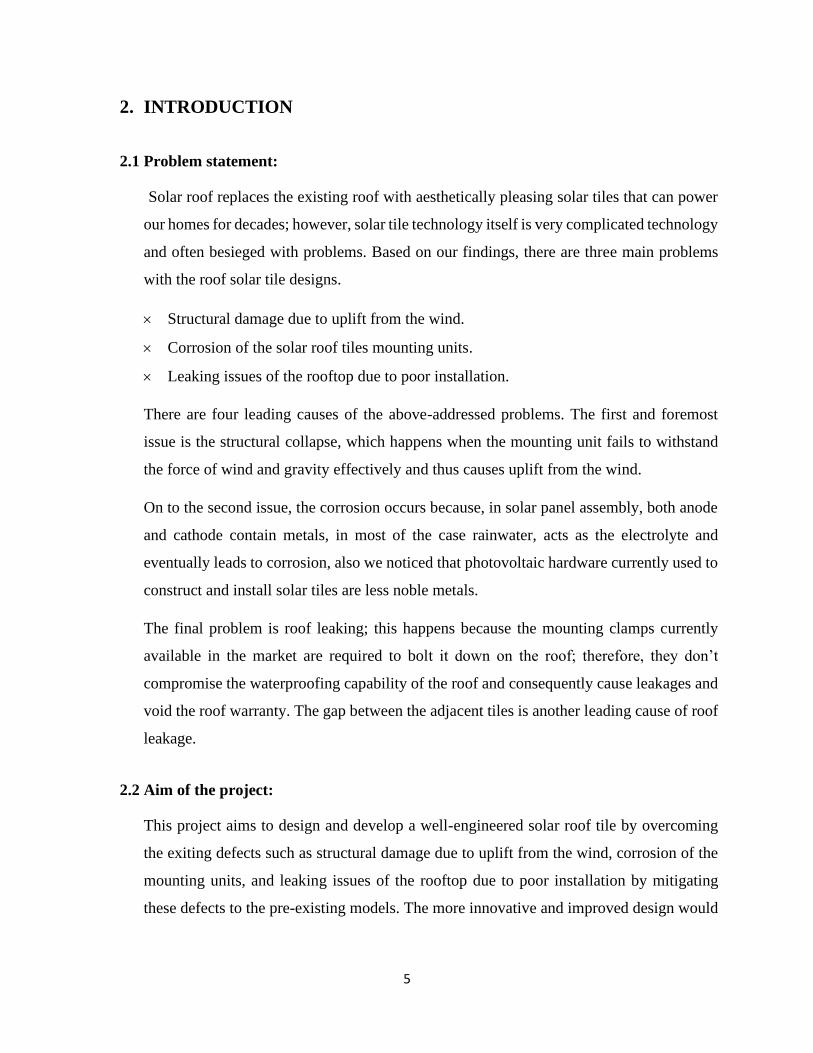
2.1 Problem statement:
Solar roof replaces the existing roof with aesthetically pleasing solar tiles that can power
our homes for decades; however, solar tile technology itself is very complicated technology
and often besieged with problems. Based on our findings, there are three main problems
with the roof solar tile designs.
Structural damage due to uplift from the wind.
Corrosion of the solar roof tiles mounting units.
Leaking issues of the rooftop due to poor installation.
There are four leading causes of the above-addressed problems. The first and foremost
issue is the structural collapse, which happens when the mounting unit fails to withstand
the force of wind and gravity effectively and thus causes uplift from the wind.
On to the second issue, the corrosion occurs because, in solar panel assembly, both anode
and cathode contain metals, in most of the case rainwater, acts as the electrolyte and
eventually leads to corrosion, also we noticed that photovoltaic hardware currently used to
construct and install solar tiles are less noble metals.
The final problem is roof leaking; this happens because the mounting clamps currently
available in the market are required to bolt it down on the roof; therefore, they don’t
compromise the waterproofing capability of the roof and consequently cause leakages and
void the roof warranty. The gap between the adjacent tiles is another leading cause of roof
leakage.
2.2 Aim of the project:
This project aims to design and develop a well-engineered solar roof tile by overcoming
the exiting defects such as structural damage due to uplift from the wind, corrosion of the
mounting units, and leaking issues of the rooftop due to poor installation by mitigating
these defects to the pre-existing models. The more innovative and improved design would

6
consist of the solution for the above issues and transforming the design into a physical
reality by prototyping a new model.
3. REVIEW OF LITERATURE
In this era of energy conservation, solar energy is one of the most untapped, yet obvious
ones. As with any new technology, there are certain glitches here as well. This literature
review concentrates on the current issues and causative components on solar roof tiles
technology. The main problems which are identified in the problem statements are
reviewed.
3.1 Structural damage of solar roof tiles due to external loads.
In any structural component of buildings, the elements of nature play a significant role in
its lifespan. The uplift of roofing structures due to wind is one of the main issues that can
plague the Solar roof tile installations too. A study (Meroney & Neff, 2010) using
Computational Fluid Dynamics (CFD) to calculate the wind load on the structure
considering the drag and lift gives an insight into this issue, which can also be used in the
testing phase to estimate the maximum load which the structure can afford to take without
causing damage. A detailed study (Cao & Yoshida, 2013) of wind load resistance for a flat-
roofed building was done for different parameters such as single array setup, multi-array
setup, the effect of distance between arrays, the effect of building depth, etc. A lightweight
Solar roof tile was developed suitable for sloping roofs which also ensured astounding
capabilities like hurricane resistance, fire resistance owing to the specialized coatings,
flexibility in terms of moldability, the ability to withstand the external load, as well as ease
in transportation and installation (Bellavia,2015). A substantial study (Ali &
Chokwitthaya, 2017) on using Solar panels to reduce the uplift caused by wind on gable-
roofed low-rise buildings provide certain valuable insights which can be adopted in the
Solar roof tile technology as well. It lists the advantage of having a backup solar power
source after an immediate power outage, especially after a thunderstorm. The research
outlines the importance of the placement of solar panels, away from the edges and corners,
for optimal reduction of uplift forces.

7
Snowfall is yet another problem area that literally obscures the Solar Roof Tiles or
Photovoltaic (PV) units from getting an ideal exposure of Solar Energy. A recent study
(Jelle, 2013) explores the option of using a low-friction, ultra-hydrophobic material in the
BIPV unit. It also calculates an optimal slipping-angle-threshold, which ensures the
slipping away of snow crystals from the PV surface.
3.2 Corrosion of the solar roof tiles mounting units
Corrosion is another prevalent issue that is caused by the metal components in the solar
roof tile assembly, which may eventually lead to a lot of structural damage. An innovative
technology uses an Anode sacrificially for the protection of Cathode from corrosion
(Whitmore, 2019). This technology further suggests the use of an activator, which
promotes the corrosive nature of the Anode material for ensuring the continuous protection
of the Cathode material from corroding. The said activator could be included in the material
which is used for ionic conduction by fillers such as gels or liquids with alkali hydroxides.
Extensive research (Nürnberger & Köse, 2019) was done on the causes of corrosion in
terms of humidity and presence of certain elements in the atmosphere like Sulphur Dioxide,
which further transforms into Sulphurous dioxide and finally Sulphuric acid as well as the
effects brought on by the salts of Chloride. The research indicates that ‘aerosols’ in
Chloride plays a significant role in corrosion. Another case study in the same research
paper was on the effect of Timber on corrosion. The paper indicated that the Timber being
a porous material is an excellent host for moisture content and other acidic corrosive agents
from the atmosphere, thereby adding to the burden of corrosion. It further ventures into
self-metallic and bi-metallic corrosive behaviors of Aluminium, Stainless Steel, etc.
3.3 Leaking issues of the solar rooftop
Leakage is yet another common issue that needs further understanding. The design and
development of a solar roof architecture in Bangalore (Mani & Reddy, 2008) is particularly
impressive with illustrative aspects of an inter-locking system for the prevention of
leakage. The design is inspired by allowing a free flow of water so that rainwater is not
collected anywhere on the roof. The existing technology (Weber, 1983) involves the
joining of the PV unit to the roof using screws, which makes the leakage an unavoidable

8
issue in the long run. Certain variations can be tried with the usage of tar or any non-
permeable materials such as plastic to cover the joints and thereby preventing the water
from passing through it. The system also mentions the concept of using an adhesive to join
the PV unit, which needs further research for the range of its effectiveness. Another cutting-
edge work (Becerril-Romero & Giraldo, 2016) is focused on converting ceramic tiles,
which are commercially used into solar cells for BIPV purpose, a novel method of using
kesterite (Siebentritt & Schorr, 2012) technology.
3.4 conclusion
A comprehensive literature survey concerning the current issues in the solar roof tile
industry is done. The four fundamental issues reviewed are damage to the structure due to
wind and the resulting uplift, snowfall obscuring the PV units, corrosion of the metallic
components, and leakage. The review sheds light on specific solutions for the identified
issues as well. Additionally, certain cutting-edge technologies such as the novel kesterite
technology and conversion of commercial ceramic tiles for BIPV purposes are also
identified, which require further research. In the past many years, the design of the
photovoltaics received enough attention; however, the design and analysis of solar roof
mounting unit have not been concentrated much. The futuristic technology of Solar Roof
Tiles is promising even though it requires a considerable amount of research and
modifications to meet all the challenges it may encounter.

9
4. METHODOLOGY
The methodology here clearly defines how to proceed, how to measure the progress, and
what constitutes the success of this entire project. The methodological approach of this
project consists of five stages:
1) Study of current designs of solar tiles and local weather conditions in New Zealand
2) Identifying the critical load acting areas and clamping system
3) Design and development of ideal clamping unit with a waterproofing membrane in
place.
4) Study about anodizing and surface protection method to avoid oxidation.
5) Fabricate a fully functional prototype to test the product features in real world
conditions
4.1 Study of current designs of solar tiles and local weather conditions in New
Zealand:
The investigation of existing solar tiles available in the market is a necessary ingredient for
creating, developing, and delivering a successful solution for the addressed problems. The
below table depicts different types of solar panels available in the New Zealand market,
and each varies in their dimensions and efficiency.
Table 1: Tile Comparison
Further research is required to provide practical evidence of the issues and this can be done
in two effective ways.
S/N Product Self-weight Efficiency
1 Tesla solar tiles 8-10 lbs 15%
2 Apollo II tile 3.2 lbs 16%
3 SunTegra tile 3.0 lbs 15%
6 Bristile 6 ~ 9 lbs 16%
7 Tractile 4 ~ 6 lbs 20%
10
✓ Visit Zero Energy House built in Auckland to get the designs and clamping methods
used.
✓ Contact the solar tiles companies for the brochure and details of the tiles
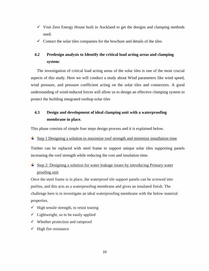
4.2 Predesign analysis to Identify the critical load acting areas and clamping
system:
The investigation of critical load acting areas of the solar tiles is one of the most crucial
aspects of this study. Here we will conduct a study about Wind parameters like wind speed,
wind pressure, and pressure coefficient acting on the solar tiles and connectors. A good
understanding of wind-induced forces will allow us to design an effective clamping system to
protect the building integrated rooftop solar tiles
4.3 Design and development of ideal clamping unit with a waterproofing
membrane in place.
This phase consists of simple four steps design process and it is explained below.
Step 1 Designing a solution to maximize roof strength and minimize installation time
Timber can be replaced with steel frame to support unique solar tiles supporting panels
increasing the roof strength while reducing the cost and insulation time.
Step 2: Designing a solution for water leakage issues by introducing Primary water
proofing unit
Once the steel frame is in place, the waterproof tile support panels can be screwed into
purlins, and this acts as a waterproofing membrane and gives an insulated finish. The
challenge here is to investigate an ideal waterproofing membrane with the below material
properties.
✓ High tensile strength, to resist tearing
✓ Lightweight, so to be easily applied
✓ Whether protection and rainproof
✓ High fire resistance

11
Step 3: Designing solar tiles supporting bars
On top of the insulated sheet (water proof tile support sheet), battens can be installed to
support the solar tiles using specially designed fixing screws.
Step 4: Designing locking mechanism and spacers to accommodate solar tiles
Link channels with a secured locking mechanism can be used to space the batten to
accommodate solar tiles. Link channels can be locked into the lower batten. Here we need to
identify the critical load acting areas.
Each link channel is also essential in waterproofing the roof. Should a storm hit, the excess
rainwater flows into the link channel then out on to the tile below, keeping the roof waterproof
and free from debris. The gap between solar inserts and tile support panels underneath ensures
valuable airflow inside the roof cavity, which in turn maximizes solar energy output.
Step 5: Conduct post design analysis to identify the critical loading areas
CFD provides a numerical approach to perform a cost-effective analysis for pressure loads and
dynamic wind loads acting on solar roof tiles in a fast and efficient way. Areas of complex
recirculating flow and localized vortices are easily simulated and identified for design
improvements.
✓ SolidWorks simulation speeds up decision making by introducing different load to tiles
and mounting parts in a precise, realistic computer environment.
The numerical analysis presents quantitative data for pressure, force, and velocity that is easy
to comprehend and highly detailed.
4.4 Study about anodizing and surface protection method to avoid oxidation.
This phase investigates cost-effective anodizing coating and surface protection methods to
protect steel frames, battens, and link channels from oxidation. Anodizing protects hardware
against further oxidation.

12
4.5 Fabricate a fully functional prototype
This phase is to test the product features in real-world conditions. Two sets of building-
integrated solar tiles have to be purchased. The fabrication and test phase includes the
following:
Fabrication of the clamps, and mounting unit as per the proposed design.
Integrating the waterproofing membrane.
Test the prototype in real-world conditions.
After the test phase, a detailed test report with findings and future recommendation have to
be prepared.

13
5.0 PROJECT LIMITATIONS:
The limitations to the methodology exist as restraints of the following:
a. Time
b. Cost
c. Performance
a. Time:
Time is constrained, and by November, the final prototype should be ready. In this project,
designing and CFD analysis are going to be the most time-consuming task. Several redesigns might
be needed to find the right solutions for the identified problems. The lack of time will automatically
reduce the amount of research done on each topic.
b. Cost:
The maximum budget that Wintec provides for this project is 1000 NZD. To complete this project
in that given budget correct planning and execution is required. The software for the design and
analysis is provided free by Wintec. But the solar tiles costs and the material costs cannot be
determined at this stage of the project. There are chances that the actual costs could overrun the
budget. For example, when buying a solar tile, the standard shipping might be free, but in this case,
the time is limited, so we should look for faster options.
c. Performance
The performance is another main factor that determines the outcome of this project. If a team
member fails to do a task in the given time, that will affect the project as a whole.
14
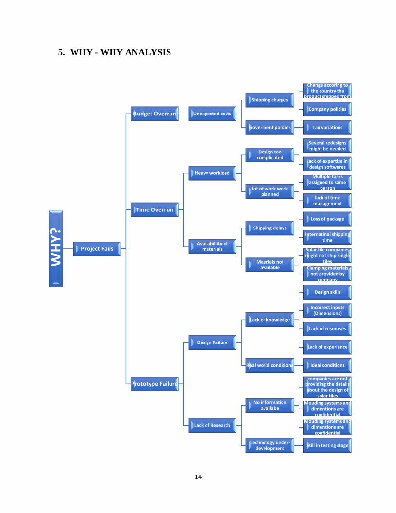
5. WHY - WHY ANALYSIS
WH
Y?
Project Fails
Budget Overrun Unexpected costs
Shipping charges
Change accoring to the country the
product shipped from
Company policies
Goverment policies Tax variations
Time Overrun
Heavy workload
Design too complicated
Several redesigns might be needed
lack of expertise in design softwares
lot of work work planned
Multiple tasks assigned to same
person
lack of time management
Availabiliity of materials
Shipping delays
Loss of package
Internatinal shipping time
Maerials not available
Solar tile companies might not ship single
tiles
Clamping materials not provided by
company
Prototype Failure
Design Failure
Lack of knowledge
Design skills
Incorrect inputs (Dimensions)
Lack of resourses
Lack of experience
Real world conditions Ideal conditions
Lack of Research
No information availabe
companies are not providing the details about the design of
solar tiles
Mouding systems and dimentions are
confidential
Mouding systems and dimentions are
confidential
Technology under-development
Still in testing stage

15
WH
Y?
Current Issues
Roof Leakage
Drilling many holes on the roof
Design of clampsLack of design
research
Wateproof Seals not used
Cost
Contractor unaware of
waterproofing
Oudated machinery
Hign cost of new machines
Availability of latest equipments
Gap between tiles
Design of TilesLack design
research
Design of clampsLack of Desin
Research
Tilting of tiles
WindClimate conditions
in an areaHign Speed of wind
Clamping Method Design of clampsLack of proper
design research
Corossion
Environment
Climatic parameters
Rain, temperacture and humidity
Atmospheric pollution
Acidic particles, quality of
precipitation
Nature of the metals
Galvanic corossionUsage of dissimilar
metals

16
6. SWOT Analysis
STRENGTHS
✓ CFD software packages provided
by Wintec help to perform a cost-
effective analysis in a fast, accurate
way.
✓ The knowledge about Solidworks
(A 3D modelling and analysis tool)
helps us to do design improvements
and analysis under one roof.
✓ Excellent technical writing skills
help us to communicate our ideas
and prepare high quality, well-
versed documentation.
OPPORTUNITIES
✓ We can effectively solve issues of
leakages, tilting of solar tiles, and
corrosion issues by design
innovation.
✓ We can commercialize our
solutions.
✓ We can get an opportunity to
present our solutions to market
leaders in solar tiles.
WEAKNESS
Lack of specialized knowledge in
Ansys (a highly advanced
simulation tool), which is superior
to Solidworks when it comes to
CFD.
We have only intermediate
knowledge in computational fluid
dynamics.
THREATS
Restriction to use Wintec facilities
due to the ongoing pandemic.
Time constraints. The prototype
and documentation should be ready
by early November 2020.
International shipping delays. Solar
tiles are not readily available in the
local market.
Unexpected design failure might
occur in real-world conditions.
17
7. CONTIGENCY OF THREATS
As a part of contingency planning, we took interim measures to respond to threats, and it is given
below.
1. Easy to use student edition of Ansys allows us to complete CFD analysis remotely at our
comfort. Wintec can allow workshop access by limiting the number of students coming
into their facility.
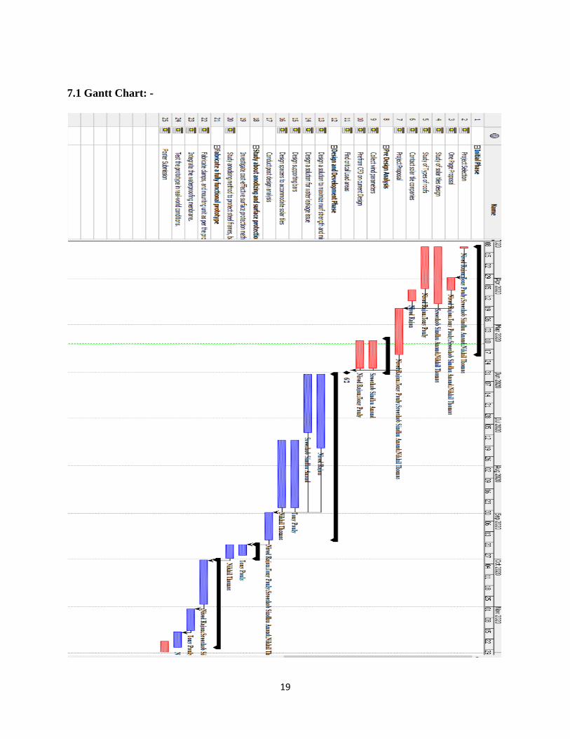
2. A Gantt chart helps us to view the start and end dates of the project in a straightforward
view so that we can timely track the schedule and manage time efficiently to complete the
project on time.
3. Decide on and order parts in advance, allow three months for parts to arrive. Design and
fabricate clamps before the solar tiles arrive.
4. Select a promising solution. Rapid prototyping will allow us to do some design
modification to meet the project objectives.
8. PROJECT PLAN
1) Study of current designs of solar tiles.
a) Visit Zero Energy House built in Auckland to get the designs and clamping methods used.
b) Contact the solar tiles companies for the brochure and details of the tiles
2) Predesign analysis to Identify the critical load acting areas and clamping system
a) Collect wind parameters and local weather conditions in NZ
b) Perform CFD using Solid works
c) Pinpoint critical loading areas of solar tiles
3) Design and development phase
a) Design a solution to maximize roof strength and minimize installation time

18
b) Design a solution for water leakage issues
c) Design supporting bars
d) Design spacers to accommodate solar tiles
e) Conduct post design analysis
4) Study about anodizing and surface protection method to avoid oxidation.
a) Investigate cost-effective surface protection method
b) Study anodizing method to protect steel frames, battens, and link channels
5) Fabricate a fully functional prototype
a) Fabricate clamps, and mounting unit as per the proposed design.
b) Integrate the waterproofing membrane.
c) Test the prototype in real-world conditions.
19
7.1 Gantt Chart: -

20
9. HAND SKETCHES OF DESIGN SOLUTIONS
Hand sketches are an essential part of the design and development process. We made the hand sketches of
our concept to convey our ideas and demonstrate our concept and functionality before designing it using a
3D modeling software.
9.1 Design and development stage 1
Figure 1: Design and development stage 1
9.2 Design and development stage 2
Figure 2: Design development stage 2

21
9.3 Design and development stage 3
Figure 3: Design and development stage 3
9.4 Design and development stage 4
Figure 4: Design and development stage 4

22
10. RESOURCES WITH BUDGET
We have a Wintec budget for each student in our group; this will cover initial site visits and study.
The software we require for design and CFD is available through our Wintec student access. Final
project costing is dependent on the finalized design, which is the next step in our process. The
estimate is given in the below table.
Table 2: Resource with budget
S/N Resource type Rate
/unit
(NZD)
Quantity Subtotal
(NZD)
Remarks
01 Transportation 30 03 90 to visit site and material
purchase
02 C21 solar tiles 80 02 160
03 Solid works/3D
modelling and CFD
tool
0 0 The software we require
for design and CFD is
available through our
Wintec student access
04 Galvanized frame 14 08 112 To improve the roof
strength
05 Waterproof membrane
sheet
60 01 60 The material is yet to
decide, and costing is
dependent on the finalized
design
06 Fabricated link
channels
6 04 24
07 Fabricated Batten to
lock the tiles
4 08 32
08 Anodizing and surface
protection
06 12 72
Subtotal (NZD) 550
23
11. REFERENCES
1. US6453629B1 - Roofing tile having photovoltaic module to generate power. (n.d.).
Retrieved from https://patents.google.com/patent/US6453629B1/en
2. Meroney, R. N., & Neff, D. E. (2010, May). Wind effects on roof-mounted solar
photovoltaic arrays: CFD and wind-tunnel evaluation. In The Fifth International
Symposium on Computational Wind Engineering (CWE 2010).
3. Cao, J., Yoshida, A., Saha, P. K., & Tamura, Y. (2013). Wind loading characteristics of
solar arrays mounted on flat roofs. Journal of Wind Engineering and Industrial
Aerodynamics, 123, 214-225.
4. Jelle, B. P. (2013). The challenge of removing snow downfall on photovoltaic solar cell
roofs in order to maximize solar energy efficiency—Research opportunities for the future.
Energy and Buildings, 67, 334-351.
5. Bellavia, C. (2015). U.S. Patent No. 9,038,330. Washington, DC: U.S. Patent and
Trademark Office.
6. Aly, A. M., Chokwitthaya, C., & Poche, R. (2017). Retrofitting building roofs with
aerodynamic features and solar panels to reduce hurricane damage and enhance eco-
friendly energy production. Sustainable Cities and Society, 35, 581-593.
7. Whitmore, D. W. (2019). U.S. Patent Application No. 15/695,515.
8. Bei, U., & Von Aufdach-Photovoltaikanlagen, T. R. Ä. G. E. R. K. O. N. S. T. R. U. K. T.
I. O. N. E. N. (2019). Causes and mechanisms of corrosion for supporting structures of
rooftop photovoltaic systems. Otto-Graf-Journal, 18.

24
9. Mani, M., Reddy, B. V. V., Sreenath, M., Lokabhiraman, S., & Anandrao, N. (2008).
Design of a climate-responsive BIPV research facility in Bangalore. In Proceedings of
ISES World Congress 2007 (Vol. I–Vol. V) (pp. 356-360). Springer, Berlin, Heidelberg.
10. Weber, R. D. (1983). U.S. Patent No. 4,375,805. Washington, DC: U.S. Patent and
Trademark Office.
11. Becerril-Romero, I., Giraldo, S., López-Marino, S., Placidi, M., Sánchez, Y., Sylla, D., ...
& Pistor, P. (2016). Vitreous enamel as sodium source for efficient kesterite solar cells on
commercial ceramic tiles. Solar Energy Materials and Solar Cells, 154, 11-17.
12. Siebentritt, S., & Schorr, S. (2012). Kesterites—a challenging material for solar cells.
Progress in Photovoltaics: Research and Applications, 20(5), 512-519.
25
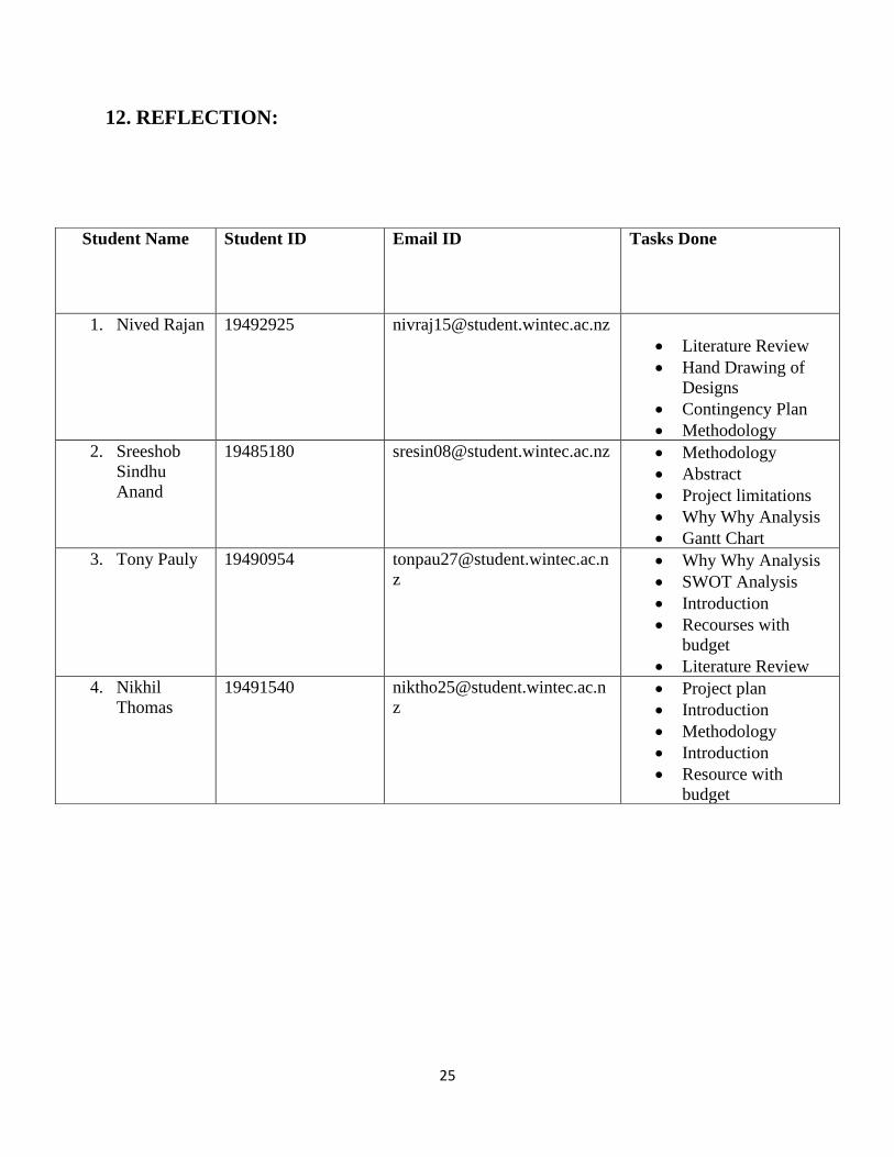
12. REFLECTION:
Student Name Student ID Email ID Tasks Done
1. Nived Rajan 19492925 [email protected]
• Literature Review
• Hand Drawing of
Designs
• Contingency Plan
• Methodology
2. Sreeshob
Sindhu
Anand
19485180 [email protected] • Methodology
• Abstract
• Project limitations
• Why Why Analysis
• Gantt Chart
3. Tony Pauly 19490954 [email protected]
z • Why Why Analysis
• SWOT Analysis
• Introduction
• Recourses with
budget
• Literature Review
4. Nikhil
Thomas
19491540 [email protected]
z • Project plan
• Introduction
• Methodology
• Introduction
• Resource with
budget

26
13. STUDENT DECLARATION
I have not copied any part of this report from any other person’s work, except as correctly
referenced. No other person has written any portion of this report for me.
1. Student Name: Sreeshob Sindhu Anand
Student declaration of the above ___________________________________ signed.
2. Student Name: Tony Pauly
Student declaration of the above ___________________________________ signed.
3. Student Name: Nived Rajan
Student declaration of the above ___________________________ signed.
4. Student Name: Nikhil Thomas
Student declaration of the above ___________________________________ signed.