
Optimal Resource Allocation in Federated Metacomputing Environmentssubieta/prace...
204
WARSAW UNIVERSITY OF TECHNOLOGY Faculty of Electronics and Information Technology Ph.D. THESIS Paweł Rubach, M.Sc. Optimal Resource Allocation in Federated Metacomputing Environments Supervisor Professor Kazimierz Subieta, Ph.D., D.Sc. Warsaw, 2010
Transcript of Optimal Resource Allocation in Federated Metacomputing Environmentssubieta/prace...
WARSAW UNIVERSITY OF TECHNOLOGY
Faculty of Electronics and Information Technology
Ph.D. THESIS
Paweł Rubach, M.Sc.
Optimal Resource Allocation in Federated Metacomputing
Environments
Supervisor
Professor Kazimierz Subieta, Ph.D., D.Sc.
Warsaw, 2010

To my family and friends

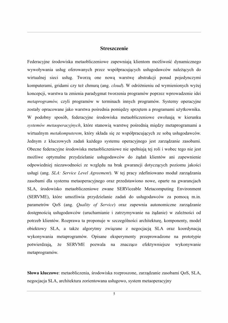
Streszczenie
Federacyjne środowiska metaobliczeniowe zapewniają klientom możliwość dynamicznego
wywoływania usług oferowanych przez współpracujących usługodawców należących do
wirtualnej sieci usług. Tworzą one nową warstwę abstrakcji ponad pojedynczymi
komputerami, gridami czy też chmurą (ang. cloud). W odróżnieniu od wymienionych wyżej
koncepcji, warstwa ta zmienia paradygmat tworzenia programów poprzez wprowadzenie idei
metaprogramów, czyli programów w terminach innych programów. Systemy operacyjne
zostały opracowane jako warstwa pośrednia pomiędzy sprzętem a programami użytkownika.
W podobny sposób, federacyjne środowiska metaobliczeniowe ewoluują w kierunku
systemów metaoperacyjnych, które stanowią warstwę pośrednią między metaprogramami a
wirtualnym metakomputerem, który składa się ze współpracujących ze sobą usługodawców.
Jednym z kluczowych zadań każdego systemu operacyjnego jest zarządzanie zasobami.
Obecne federacyjne środowiska metaobliczeniowe nie spełniają tej roli i wobec tego nie jest
możliwe optymalne przydzielanie usługodawców do żądań klientów ani zapewnienie
odpowiedniej niezawodności ze względu na brak gwarancji dotyczących poziomu jakości
usługi (ang. SLA: Service Level Agreement). W tej pracy zdefiniowano moduł zarządzania
zasobami dla systemu metaoperacyjnego oraz przedstawiono nowe, oparte na gwarancjach
SLA, środowisko metaobliczeniowe zwane SERViceable Metacomputing Environment
(SERVME), które umożliwia przydzielanie zadań do usługodawców za pomocą m.in.
parametrów QoS (ang. Quality of Service) oraz zapewnia autonomiczne zarządzanie
dostępnością usługodawców (uruchamianie i zatrzymywanie na żądanie) w zależności od
potrzeb klientów. Rozprawa ta proponuje w szczególności architekturę, komponenty, model
obiektowy SLA, a także algorytmy związane z negocjacją SLA oraz koordynacją
wykonywania metaprogramów. Opisane eksperymenty przeprowadzone na prototypie
potwierdzają, że SERVME pozwala na znacząco efektywniejsze wykonywanie
metaprogramów.
Słowa kluczowe: metaobliczenia, środowiska rozproszone, zarządzanie zasobami QoS, SLA,
negocjacja SLA, architektura zorientowana usługowo, system metaoperacyjny
5
Abstract
Federated metacomputing environments make available to requestors the ability to
dynamically invoke services offered by collaborating providers in the virtual service network.
They create a new layer of abstraction on top of current grids, clouds and single computer
platforms, one that in contrast to aforementioned solutions, introduces a new paradigm that
changes the way programs are written. This new paradigm is the concept of metaprograms –
programs written in terms of other programs. For single computer platforms, operating
systems were introduced as an intermediary layer between the hardware and the user's
applications. Similarly, federated metacomputing environments evolve into metaoperating
systems that form an intermediary layer between metaprograms and the virtual metacomputer
composed of collaborating services. One of the crucial roles of any operating system is
resource management. Current federated metacomputing environments do not address this
issue and, consequently the assignment of providers to customer’s requests cannot be
optimized and cannot offer high reliability without relevant SLA guarantees. This dissertation
defines a resource management module of a metaoperating system by proposing a new SLA-
based SERViceable Metacomputing Environment (SERVME) that is capable of matching
providers based on QoS requirements and performing on-demand provisioning and
deprovisioning of services according to dynamic requestor's needs. In particular, the
dissertation defines the architecture and the components, introduces a QoS/SLA model, and
proposes algorithms for SLA negotiation and execution of metaprograms with SLA
guarantees. The validation of a prototype of the proposed solution shows that the system leads
to significant optimization of the execution of metaprograms.
Keywords: Metacomputing, Distributed Computing, Resource Management, QoS, SLA, SLA
negotiation, Service-Oriented Architecture, Service Object-Oriented Architecture,
Metaoperating System.
6
Acknowledgments
I would like to express my gratitude to my thesis director, Professor Kazimierz Subieta, for
his invaluable advice and help from the very first moment when I approached him as a
confused student, with no clear idea of where I was heading. He supported me in my efforts to
obtain a Fulbright fellowship that changed my academic life completely. This endeavor was
successful and I spent a year at Texas Tech University, Texas, USA, where I met Professor
Michał Sobolewski. At that time, I was searching in the dark, trying to find inspiration in
various domains of computer science, but none of the ideas I was exploring was satisfactory.
It was Professor Sobolewski who infused creative life into my work. He showed me that it
was possible to combine innovative theoretical work with cutting edge practical applications
in the field of concurrent engineering. My pessimism turned into enthusiasm.
I will always remember the first visit in Professor Sobolewski's office in Lubbock,
which lasted over three hours. During this appointment and innumerable later appointments,
we discussed not only the details of my project but many issues of general nature that helped
enormously to shape my computer science world view. At times, the discussions would take
us beyond our professional field into the realm of philosophy. His inspiring criticism of my
work and his attachment to detail and perfection challenged me to the utmost.
I would like to thank my professors, instructors and colleagues at the Warsaw School
of Economics, where I learned about the fundamentals in my field of specialization. It was so
reassuring to know that I could always count on getting good advice and as much help as I
needed.
I was greatly inspired by an exchange of ideas with Dennis Reedy, the architect and
creator of the Rio Project, and Raymond M. Kolonay, Principal Aerospace Engineer at the Air
Force Research Laboratory in Dayton, Ohio, USA. Dennis Reedy introduced me to the
architecture of the Rio provisioning framework that was an invaluable resource of ideas for
my work. His advice was instrumental in the integration of the Rio framework with the
prototype of the proposed solution. Ray Kolonay led me through the maze of optimization
techniques and algorithms and helped me identify the research methods that were appropriate
for my work.
7
I am also grateful to the Orange Labs, particularly to Andrzej Tucholski and Emil
Kowalczyk for much fruitful discussion and invaluable technical help with finding the
equipment that was crucial for running my experiments.
I would also like to thank my friends, Iga Korneta, Jerzy Orłowski and Jacek Jońca-
Jasiński who helped me find real world material to run my tests and validate my hypotheses.
Last but not least, I would like to thank my family and all those who supported me at
every stage in my work, from the inception to the completion of this dissertation.
8
Table of Contents
Introduction...............................................................................................................................17
1.1. Problem statement........................................................................................................19
1.2. Dissertation outline.......................................................................................................20
Chapter 2. Background and Literature Review.........................................................................23
2.1. Evolution of the computing platform...........................................................................24
2.2. Operating systems .......................................................................................................25
2.3. Developments of the processor....................................................................................27
2.3.1. Supercomputing and High Performance Computing............................................27
2.3.2. Distributed vs. parallel computing........................................................................28
2.3.3. Virtual processors.................................................................................................29
2.4. Grid computing.............................................................................................................31
2.4.1. Grid computing technologies................................................................................33
2.4.1.1. Globus Toolkit...............................................................................................34
2.4.1.2. UNICORE.....................................................................................................34
2.4.1.3. gLite .............................................................................................................36
2.4.1.4. Sun Grid Engine............................................................................................37
2.4.1.5. Legion...........................................................................................................38
2.4.2. Critical discussion on grid computing..................................................................38
2.5. Metacomputing.............................................................................................................40
2.6. The metacomputing platform.......................................................................................43
2.6.1. 8 fallacies of distributed computing.....................................................................44
2.6.2. Jini........................................................................................................................44
2.6.3. SORCER and metaprogramming.........................................................................46
2.6.4. Service messaging and exertions.........................................................................49
2.6.5. SORCER metacomputing platform......................................................................50
2.7. Resource management in distributed computing.........................................................52
2.7.1. QoS/SLA model....................................................................................................54
2.7.2. SLA negotiation....................................................................................................55
2.7.3. Project Rio............................................................................................................56
9
2.8. Optimal resource allocation and management.............................................................57
2.9. Summary......................................................................................................................58
Chapter 3. Requirements Analysis............................................................................................59
3.1. Social metaphor of SERVME.......................................................................................59
3.2. Functional and technical requirements.........................................................................61
3.3. Use case analysis.........................................................................................................62
3.3.1. Use cases related to the execution of an exertion.................................................62
3.3.2. Use cases related to the administration of SLAs..................................................72
3.4. Use case scenario from the real world..........................................................................75
3.5. Summary......................................................................................................................76
Chapter 4. Architecture and Design..........................................................................................77
4.1. Methodology, modeling tools and approaches............................................................77
4.1.1. Methodology.........................................................................................................78
4.1.2. Commonality variability analysis.........................................................................79
4.1.3. Cohesive design....................................................................................................80
4.1.4. UML diagrams......................................................................................................80
4.2. Conceptual architecture................................................................................................80
4.3. QoS/SLA model...........................................................................................................83
4.3.1. Basic structures: QosContext................................................................................84
4.3.2. Decision to abandon SLA negotiation scenarios in QosContext..........................91
4.3.3. Service Level Agreements contract model: SlaContext.......................................92
4.4. Architecture – components and interfaces ...................................................................96
4.4.1. SERVME component architecture........................................................................96
4.5. Interactions within the framework ............................................................................100
4.5.1. Simple exertions: tasks.......................................................................................101
4.5.1.1. Simplified flow of the SLA negotiation......................................................101
4.5.1.2. Detailed flow: preliminary selection of providers......................................102
4.5.1.3. Negotiation..................................................................................................103
4.5.1.4. SLA acceptance and signing.......................................................................106
4.5.1.5. On-demand provisioning............................................................................106
4.5.1.6. SLA monitoring and management..............................................................107
4.5.1.7. Deprovisioning services..............................................................................108
10
4.5.2. SLA negotiation use-case...................................................................................109
4.5.3. SLA prioritization as a way towards managing a cloud using SERVME...........112
4.5.4. SLA Prioritizer....................................................................................................113
4.5.5. Composite exertions: jobs...................................................................................114
4.5.6. Jobs with the Push access method......................................................................116
4.5.7. Space-based computing......................................................................................118
4.5.8. Jobs with the Pull access method........................................................................120
4.5.8.1. SLA negotiation in space computing..........................................................121
4.5.8.2. Selecting the best SLA offer........................................................................123
4.5.8.3. Leasing SLA offers.....................................................................................124
4.5.8.4. SLA acceptance, signing and execution......................................................124
4.5.8.5. SLA envelops..............................................................................................125
4.5.8.6. Distributed arrays in space .........................................................................126
4.5.9. Discussion on job execution optimization..........................................................127
4.5.9.1. Multiobjective optimization – formal definition and algorithms................127
4.5.9.2. Job optimization: problems, discussion and proposed solutions................131
4.5.9.3. Incremental multiobjective optimization methods......................................133
4.5.9.4. Proposed optimization methods for different types of jobs........................135
4.6. Summary...................................................................................................................136
Chapter 5. Validation...............................................................................................................137
5.1. Validation and verification methods...........................................................................138
5.2. Conceptual validation.................................................................................................140
5.2.1. SERVME model of packages and classes...........................................................140
5.2.2. Technical architecture of SERVME....................................................................145
5.3. Operational validation: introducing a real world use case scenario...........................146
5.3.1. Protein sequencing using Rosetta.......................................................................146
5.3.2. Deployment used during the validation..............................................................147
5.3.3. Validation of use-cases.......................................................................................148
5.3.4. Validation of running composite exertions: performance analysis.....................151
5.3.4.1. Assumptions................................................................................................151
5.3.4.2. Discussion on results...................................................................................153
5.3.5. Measured communication overhead of SLA management.................................159
11
5.4. Summary....................................................................................................................160
Chapter 6. Conclusions and Future Work...............................................................................161
6.1. Future work................................................................................................................163
Chapter 7. Glossary.................................................................................................................165
Chapter 8. Bibliography..........................................................................................................169
Appendix A SERVME interfaces................................................................181
12
Index of Figures
Figure 1: The evolution of computing platforms......................................................................25
Figure 2: Evolution of the processor.........................................................................................29
Figure 3: Modern computing platforms....................................................................................30
Figure 4: DRMAA and its implementations in various Grid frameworks. Source: [27]..........32
Figure 5: Globus Toolkit components. Source: [29].................................................................33
Figure 6: UNICORE architecture. Source: [33]........................................................................35
Figure 7: Business logics in grid computing vs. metacomputing.............................................41
Figure 8: Jini Service Object-Oriented Architecture (SOOA) vs. Web Services......................45
Figure 9: Exertion execution in SORCER................................................................................47
Figure 10: SORCER metacomputing platform.........................................................................51
Figure 11: Dynamic provisioning. Source: Rio project's website.............................................56
Figure 12: Use case diagram: Executing exertion with QoS....................................................63
Figure 13: Use case diagram - SERVME administration..........................................................72
Figure 14: Deployment diagram showing the requirements for the proposed framework.......76
Figure 15: Design methodology................................................................................................78
Figure 16: SERVME conceptual architecture...........................................................................82
Figure 17: SLA object model: QoS requirements.....................................................................85
Figure 18: SLA object model: System Requirements...............................................................86
Figure 19: SLA object model: Organizational Requirements...................................................87
Figure 20: SLA object model: Metrics......................................................................................88
Figure 21: SLA object model: SLA parameters........................................................................90
Figure 22: SLA object model: Service cost..............................................................................90
Figure 23: SLA object model: QoS configuration....................................................................91
Figure 24: SLA object model - SLA context.............................................................................93
Figure 25: SLA object model....................................................................................................95
Figure 26: SERVME architecture.............................................................................................96
Figure 27: SERVME SLA negotiation: Top level activity diagram........................................101
Figure 28: SERVME SLA negotiation: Interactions between SERVME components...........102
Figure 29: SLA negotiation: Top level sequence diagram......................................................103
13
Figure 30: SLA negotiation: Sequence diagram - QosCatalog negotiates SLA.....................104
Figure 31: SERVME SLA negotiation: Monitoring................................................................107
Figure 32: Deleting SLA from SlaMonitor.............................................................................108
Figure 33: SLA negotiation example: provider to be provisioned..........................................110
Figure 34: SLA negotiation example: SLA update.................................................................111
Figure 35: Job types in SORCER............................................................................................115
Figure 36: Processes use spaces and simple operations to coordinate. Source: [113]............119
Figure 37: SLA negotiation in space computing.....................................................................122
Figure 38: A multilevel tree of an example job.......................................................................131
Figure 39: Incremental task-level Multiobjective Optimization applied to a PULL type job
with sequential flow................................................................................................................134
Figure 40: Simplified version of the modeling process. Source: R. Sargent: [129]...............139
Figure 41: SERVME class model...........................................................................................141
Figure 42: SERVME services class model..............................................................................142
Figure 43: Class model of the Exertion extended to handle SLA management .....................143
Figure 44: Class model of SORCER providers extended to handle resource management. . .144
Figure 45: SERVME technical architecture............................................................................145
Figure 46: Validation use case deployment.............................................................................148
Figure 47: SLA Monitor showing a list of SLA contracts......................................................149
Figure 48: Monitoring Service Provider's QoS parameters....................................................150
Figure 49: Viewing Service Provider's platform capabilities..................................................151
Figure 50: Performance analysis: execution time for Push type parallel jobs........................153
Figure 51: Performance analysis: execution time for Pull type parallel jobs.........................154
Figure 52: Performance analysis: execution time for Pull type sequential jobs.....................156
Figure 53: Performance analysis: cost vs. time priority - parallel jobs...................................157
Figure 54: Performance analysis: cost vs. time priority - sequential jobs..............................158
14
Index of Tables
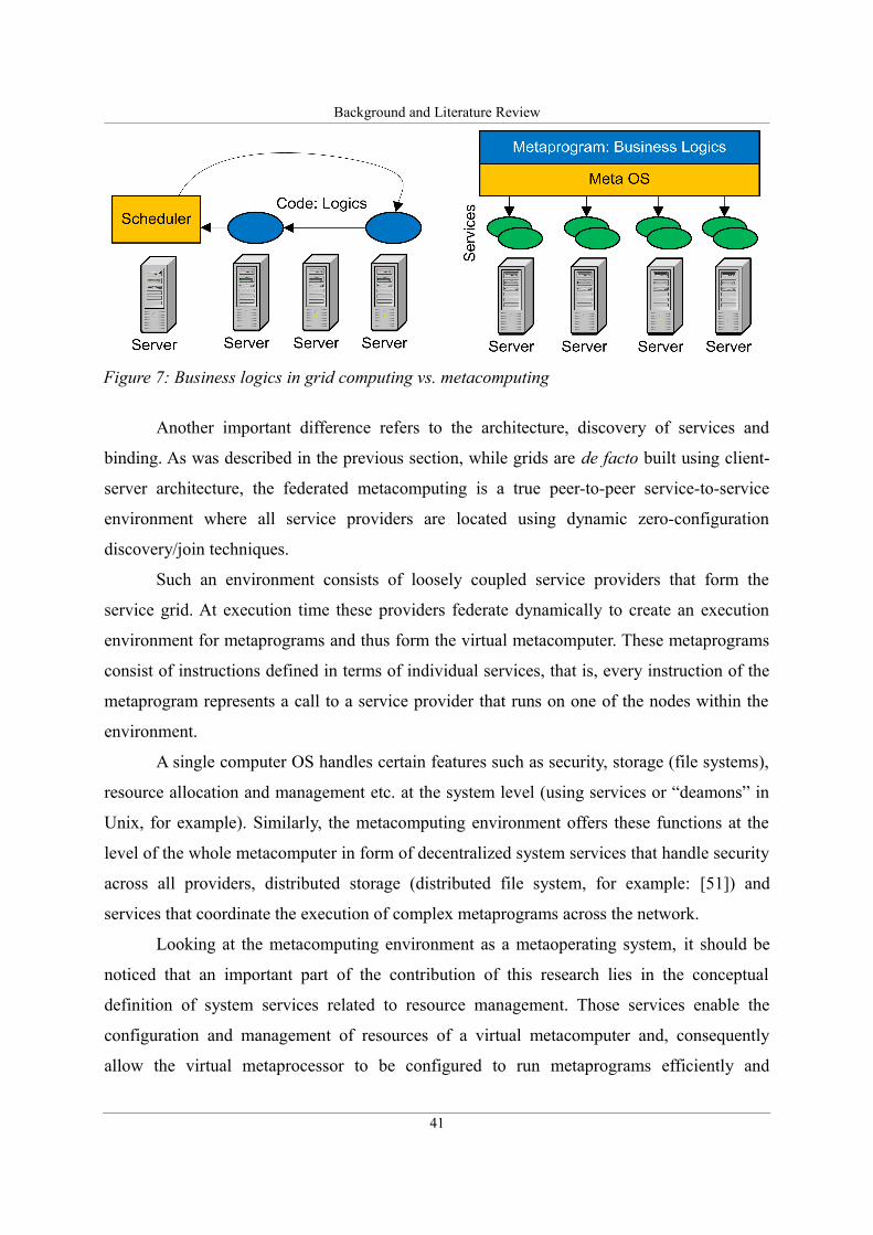
Table 1: Grid computing vs. federated metacomputing............................................................42
Table 2: Use case description: Exertion exert() with QoS........................................................64
Table 3: Use case description: Assign ProviderAccessor.........................................................65
Table 4: Use case description: Find matching Service Providers.............................................65
Table 5: Use case description: Get SLA ...................................................................................66
Table 6: Use case description: Negotiate SLA..........................................................................67
Table 7: Use case description: Get current QoS parameters.....................................................68
Table 8: Use case description: Provision new providers...........................................................69
Table 9: Use case description: Register SLA............................................................................69
Table 10: Use case description: Execute a simple exertion (task)............................................70
Table 11: Use case description: Coordinate execution of composite exertions (jobs)..............71
Table 12: Use case description: List SLAs...............................................................................72
Table 13: Use case description: Delete SLA.............................................................................73
Table 14: Use case description: Monitor QoS parameters........................................................74
Table 15: SLA negotiation use-case: QoS parameters............................................................109
Table 16: Performance analysis: execution time and cost for parallel flow composite exertions
.................................................................................................................................................155
Table 17: Performance analysis: execution time and cost for sequential flow jobs................156
Table 18: SLA acquisition overhead time: access: Push, flow: Sequential.............................159
15

Introduction
Introduction
We are at the very beginning of time for the human race. It is not unreasonable
that we grapple with problems. But there are tens of thousands of years in the
future. Our responsibility is to do what we can, learn what we can, improve the
solutions, and pass them on.
Richard Feynman
Current technological progress, particularly, in the past few decades, has demonstrated the
need for performing more and more complex computations. To meet this requirement, large
and complicated distributed systems have become essential since already in the early 1990s it
became clear that the only way to achieve substantial performance gains is to parallelize tasks
and build networks of compute nodes known today as clusters or grids. In the late 1990s grid
computing emerged as a solution to utilize distributed resources and recently the IT industry
has proposed cloud computing as a way to achieve greater computational power that would
lead towards the realization of the utility computing concept. Since every vendor has a
different definition of the cloud, there is a lot of confusion and, apart from making use of
virtualization, cloud computing does not introduce particularly many new solutions at the
conceptual level of distributed computing. One of the reasons is that similarly to grids, also in
the case of clouds, the way programmers write programs has not changed. They are still
written to be executed on a single computer. As a result, it is clear that new concepts that
reach beyond virtualized single computer platforms must be developed.
One of the concepts that addresses this problem is envisioned in the idea of federated
metacomputing. The goal is to create a new layer of abstraction on top of current grids, clouds
and single computer platforms, one that, in contrast to today's solutions, introduces a new
paradigm that changes the way programs are written. It is represented by the concept of
17
Introduction
metaprograms, that is, programs written in terms of other programs. These lower-level
programs are in fact dynamic object-oriented services. Metaprograms are not executed by
particular nodes of a cluster or a grid but instead by a network of service providers that
federate dynamically to create a virtual metacomputer and dissolve after finalizing the
execution.
Since the introduction of UNIX, operating systems (OS) evolved as an intermediary
between the hardware and the user and his/her applications. It is the role of the OS to locate
required libraries, allocate resources and execute a requested program while controlling the
hardware and allowing others to concurrently use the computer. The same should apply to the
virtual metacomputer and metaprograms. There is clearly a need to create this intermediary
layer: a virtual metaoperating system.
The foundations for the concepts of metaprogramming and metaoperating system were
laid in the FIPER project (Federated Intelligent Product EnviRonment) that was realized in
the years 2000-2003 under the sponsorship of the American National Institute of Standards
and Technology (NIST). This work evolved into the SORCER project (Service ORiented
Computing EnviRonment) that was led by Michał Sobolewski at Texas Tech University and is
continued today at the Air Force Research Laboratory and at the Polish-Japanese Institute of
Information Technology.
SORCER introduced the concept of a metaprogram and named it exertion as well as
defined the architecture and basic system services that allow exertions to be exerted (executed
by the virtual metacomputer). Even though several projects concentrated on, for example,
creating a distributed file system or on issues related to security, the SORCER metacomputing
environment still could not be regarded as a real metaoperating system because it lacked one
of the crucial elements of an operating system: resource management.
This dissertation proposes a resource management framework that is regarded as the
metaoperating system's module responsible for the allocation and management of resources.
As such, this research complements past work on the SORCER project and allows the
metacomputing platform to be regarded as a fully functional prototype of a metaoperating
system.
Much research has been done in the area of optimal resource allocation in distributed
environments, in particular, on the Service Level Agreements (SLA) management of services.
However, most approaches focus either on low-level resource allocation in clustered
18
Introduction
environments or on grids where computing tasks are assigned to particular nodes by a
centralized scheduler.
This work introduces a new approach to resource management, where all resources
available in the network are treated together and thus form the virtual metacomputer that is
capable of executing metaprograms. Since this approach uses a decentralized distributed zero-
configuration architecture where federations of service providers are created on-the-fly during
the execution time, this technique poses new challenges and requires new algorithms and a
new architecture to manage its resources in an efficient and scalable way.
1.1. Problem statement
From the conceptual point of view, the proposed solution complements the service-oriented
distributed environment by adding the necessary resource management framework. In effect a
complete metaoperating system can be built that is capable of executing metaprograms in a
distributed environment that forms the virtual metacomputer. Therefore, the hypothesis of this
work can be expressed as:
It is possible to build a system that will allow us to optimally manage the available
resources and configure the processor of the virtual metacomputer to execute
metaprograms and allocate resources using Service Level Agreements to guarantee the
requested Quality of Service parameters.
The optimality of resource management and allocation is understood in two ways.
First qualitatively as the selection of those service providers that fulfill QoS requirements and
secondly quantitatively as the minimization of a certain parameter, for example, the overall
execution time, total cost or both.
This dissertation proposes a new model and architecture of the extended
metacomputing environment. This architecture includes new system components required to
perform tasks related to resource management at the level of the whole metaoperating system.
Apart from system services, a new object-oriented QoS/SLA model is proposed as well as a
number of algorithms for dynamic SLA negotiation and the optimization of the execution of
metaprograms.
19
Introduction
1.2. Dissertation outline
The dissertation consists of seven chapters that are organized as follows.
The introduction brings forward and defines the researched problem of resource
management in federated metacomputing environments. Chapter 2 discusses the state-of-the-
art and reviews the corresponding literature related to distributed computing. It introduces the
term computing platform and describes its evolution as well as the developments of its
components, in particular, it focuses on the advancement of virtual processors and operating
systems. The later sections describe concepts related to metacomputing and present the details
of the SORCER environment and its foundations. The final sections of Chapter 2 focus on
resource management in distributed environments.
Chapter 3 defines the requested problem in greater detail by analyzing the
requirements and proposing use-cases illustrating the addressed issues on concrete examples.
The chapter describes a potential real world use-case scenario in which the proposed
framework may be deployed to efficiently manage the execution of a complex computational
task.
Chapter 4 contains the main contribution of this dissertation: the architecture and the
design of the resource management framework. Section 4.1 defines the methodology, the
modeling tools and approaches used throughout the modeling phase. Section 4.2 proposes the
conceptual architecture and identifies specific problems that must be addressed in greater
detail. They are described in later sections and include the SLA object model, component
architecture and the interactions that contain SLA negotiation algorithms and optimization
techniques.
Chapter 5 validates the proposed model. The first part discusses various approaches to
verification and validation and describes the chosen “Sargent's Circle” approach in greater
detail. According to the selected method, the validation is divided into two major parts:
conceptual validation and operational validation. Conceptual validation is discussed by
presenting the model of classes and packages and describing the technical architecture of the
proposed framework. Operational validation includes the validation of use-cases defined in
Chapter 3 and the description of experiments conducted on the deployment of the prototype in
a real world use-case of protein structure prediction. The last sections, Section 5.3.4 and
Section 5.3.5, include a performance analysis and the measurement of the overhead time
20
Introduction
related to the use of the proposed solution.
Chapter 6 summarizes the results of this research and discusses further enhancements
that should be addressed in future work. Chapter 7 contains a glossary of terms used in the
dissertation.
21

Background and Literature Review
Chapter 2.
Background and Literature Review
The advice of friends must be received with a judicious reserve; we must not give
ourselves up to it and follow it blindly, whether right or wrong.
Pierre Charron
This chapter presents the background and reviews the corresponding literature. Sections 2.1
and 2.2 explain the goal of this research and identify the areas of interest by showing how
platforms and operating systems developed and how federated metacomputing can be seen as
the next generation of distributed computing. Sections 2.3 and 2.4 review and evaluate major
large-scale computing technologies, including grid computing. Sections 2.5 and 2.6 introduce
the SORCER metacomputing platform and describe in detail the metaprogramming approach
(exertion-oriented programming [1]) as well as the underlying technologies. Section 2.7
provides details regarding other resource management frameworks and focuses on SLA
management of services, including, among other things, SLA specifications and dynamic SLA
negotiation. Section 2.8 explains how the optimality of resource allocation is understood in
this dissertation.
The goal of this research is to complement previous research activities aimed at
creating a complete platform for a distributed environment consisting of virtualized
processors, a metaoperating system, and a metaprogramming environment.
The past research on the SORCER project [2] was aimed at delivering a
metaoperating system (MOS) that could be used to run metaprograms on a virtual
metacomputer. The FIPER project [3] introduced the notion of a federation of distributed
service-oriented network-objects (services) that can be viewed as individual instructions of
23
Background and Literature Review
the processor of the virtual metacomputer. Later, the SORCER project defined the concept of
metaprogramming (programming for a distributed environment) by introducing the exertion-
oriented programming [1]. The whole platform, however, until recently was not complete, as
the SORCER MOS lacked an important aspect of an OS – a resource management
framework. It is the conceptual design, the architecture and the development of such a
framework that is the topic of this dissertation. The resource management solution proposed
here is called the SERViceable Metacomputing Environment (SERVME).
To motivate this approach, it is necessary to introduce the term “computing platform”
and show how it developed over time. The following sections describe the three key elements
of a computing platform and show how each of them evolved. These sections add more
details regarding the concept of the metaprogramming environment and underline the
conceptual and practical differences between the proposed approach and the state-of-the-art
technologies in distributed computing. In particular, the final sections of the chapter provide
an analysis and a critical appraisal of grid technology.
2.1. Evolution of the computing platform
According to Webster's definition that dates back to 1961, an Operating System (OS) is a
”software that controls the operation of a computer and directs the processing of programs (as
by assigning storage space in memory and controlling input and output functions).” [4]. This
definition underscores the role of the OS as an intermediary layer between the hardware and
the programs that perform operations useful to users. Some other definitions [5] are more
specific and mention the role of the defined application programming interface (API) that is
used by applications (programs other than the OS) to make requests for services offered by
the OS. It is significant that the API is mentioned in the later definition and that it was not
mentioned in the original definition. This shows that the term OS evolved over time and that it
was difficult to agree exactly on what an OS is and what functions it provides until the
emergence of UNIX in the 1970s.1
As Silberschatz and Galvin point out in the book “Operating System Concepts” [6] it
is easier to define what an OS is by specifying its goals. The authors name two of them:
1 To be more exact, the first version of a UNIX system called Unics (UNIplexed Information and Computing
Service) was created in the Bell Labs in 1969 and UNIX became increasingly popular in the 1970s.
24
Background and Literature Review
convenience for the user – the OS should make it easier to compute as opposed to using the
bare machine and efficient operation of the computer system. The latter is also significant
since this stresses the role of resource management as one of the two key functions of an OS.
But how these definitions and key features of an OS relate to the topic of this
dissertation? Unfortunately, it is still impossible to give a clear explanation without
introducing the term platform and looking back at the history of operating systems.
The term platform or computing platform has many meanings and in everyday jargon
often refers to an OS running on a specific hardware (for example: Windows Platform, Linux
Platform etc.). However, a more precise definition can be found on Wikipedia [7], according
to which, a platform is the hardware and software architecture that allows software to run. In
particular, it consists of a hardware architecture (mainly referring to the Central Processing
Unit (CPU)), an operating system and a programming environment [7].
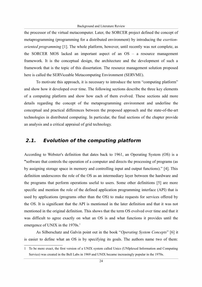
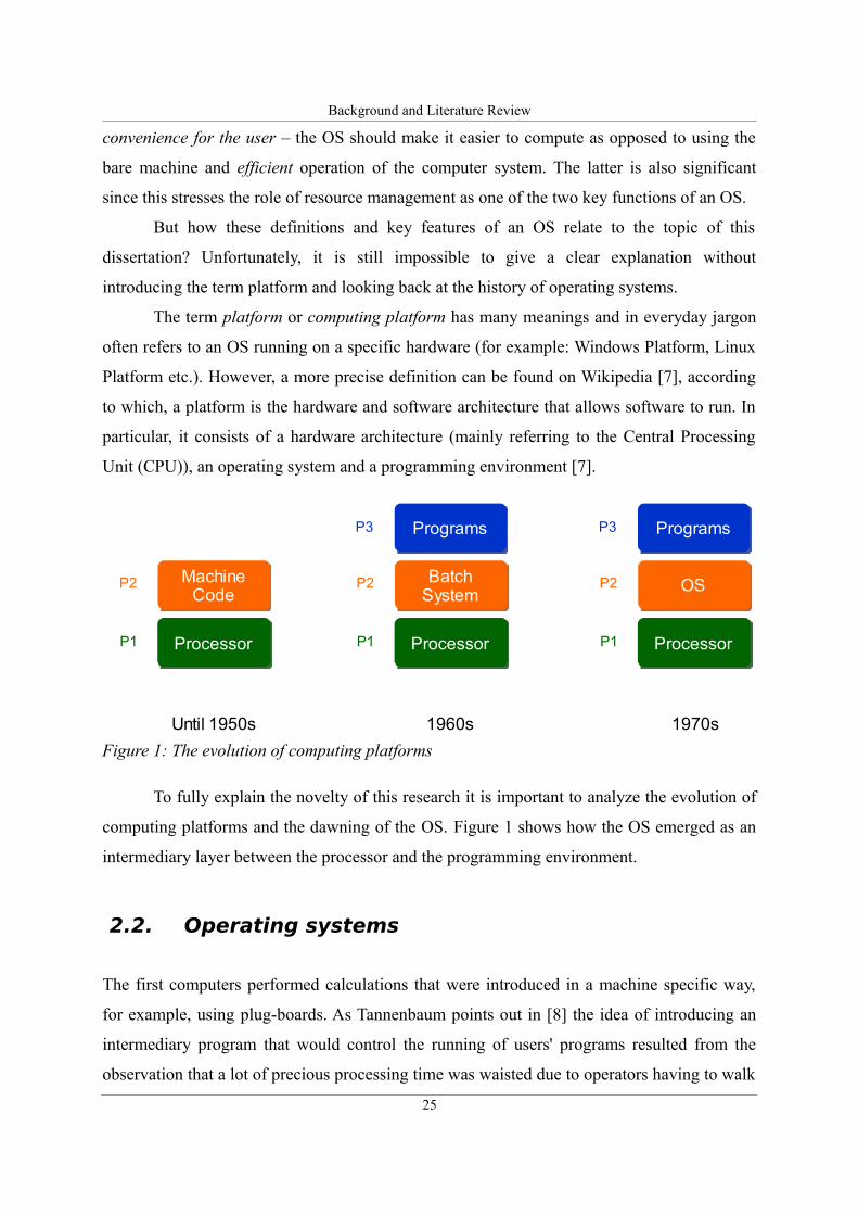
To fully explain the novelty of this research it is important to analyze the evolution of
computing platforms and the dawning of the OS. Figure 1 shows how the OS emerged as an
intermediary layer between the processor and the programming environment.
2.2. Operating systems
The first computers performed calculations that were introduced in a machine specific way,
for example, using plug-boards. As Tannenbaum points out in [8] the idea of introducing an
intermediary program that would control the running of users' programs resulted from the
observation that a lot of precious processing time was waisted due to operators having to walk
25
Figure 1: The evolution of computing platforms
Processor
MachineCode
P1
P2
Until 1950s
Processor
OS
ProgramsP3
P1
P2
1970s
Processor
Batch System
ProgramsP3
P1
P2
1960s
Background and Literature Review
around the machine room to bring required card decks that contained the program, the
FORTRAN compiler etc. This led to the development of a batch system. As Tannenbaum
mentions the original idea was to use separate, lower cost machines, such as the IBM 1401 to
read punched cards and print the results and let the expensive IBM 7094 or similar
mainframes run only the calculations [8].
A big step forward in the OS development came with the emergence of the UNIX OS
that became extremely popular, firstly because its sources were freely available (at least in the
beginning) and secondly because it was later completely rewritten in the C language which
made it easily portable between different hardware platforms. The widespread of the UNIX
system and its clones helped to unify the vision of an OS as a such and, taking into account
that UNIX was a multi-user system, the role of the resource management of an OS became
crucial.
While discussing operating systems, it is important to mention the notions of a
network operating system and a distributed operating system that were formed in the 1980s to
describe two different approaches to network-centric platforms. According to Tannenbaum [8]
a network operating system is one that connects multiple computers, however, users are aware
of their existence and can log in to remote machines and share resources. In contrast, a
distributed operating system “... is one that looks to its users like an ordinary centralized
operating system but runs on multiple independent central processing units (CPUs)”. [9] [10].
The first approach is not particularly appealing and, in today's world where almost all devices
are connected, it has simply become a reality. However, the concept of a distributed OS is far
more interesting and is in close relationship with the Computing Clusters that are already
widely implemented but still pose some research challenges.
From the point of view of this research and, in particular, the question of creating a
platform for distributed programs, neither the network OS nor the distributed OS are a
solution. The reason is that in both cases, despite changes at the OS level, the resulting
programming environments remain practically the same as in a single computer single OS
platform.
Before presenting the details of metacomputing and the concept of a metaoperating
system it is necessary to analyze the developments of the processor to show what kind of a
processor the MOS targets.
26
Background and Literature Review
2.3. Developments of the processor
The processor is the basic element of a computing platform. Processors of the first computers
occupied large rooms and contained thousands of electromechanical parts, relays or vacuum
tubes. The discovery of semiconductors and the introduction of transistors allowed processors
to be downsized. Later the development of integrated circuits, allowed processors to be built
as single electronic chips. Today it is common to have multiple processors (or cores) in a
single chip. This is an important tendency since the evolution of the processor influences
strongly the evolution of the software that controls it – that is the OS in todays' computing
platforms.
A processor may also be regarded as a more abstract entity – a software equivalent of a
chip, such as a hypervisor (virtual processor) or even a grid of service-oriented programs.
These tendencies are depicted in Figure 3 and will be discussed later in this section.
First, to keep with chronology, it is crucial to analyze the historical and current trends
in high performance computing and related domains that focus on the development of more
and more powerful processors.
2.3.1. Supercomputing and High Performance Computing
Ever since the first electronic computers were introduced in the 1940s engineers are
struggling to achieve greater and greater computational power. This field of computer science
is often referred to as Supercomputing or High Performance Computing (HPC). HPC emerged
as a scientific term that grasps all kinds of supercomputing technologies and focuses on
achieving greater performance. Within HPC there is a subdomain called High Performance
Technical Computing (HPTC) that tries to answer the question “how to build best
performance supercomputers”. As R. Espasa et al. [11] point out the term supercomputer was
coined later but the first supercomputers (Control Data 6600 and Control Data 7600) were
built already in 1963 and 1969 accordingly. These machines had scalar CPUs that as the first
ones used the RISC architecture [12]. Later the most famous series of supercomputers built by
Seymour Cray and his company – Cray Research used vector processors. The first of the
series – Cray-1 appeared in 1976 and by the mid 1980s Crays dominated the supercomputing
market. Early 1990s showed the end of the dominance of supercomputers such as the products
27
Background and Literature Review
from Cray Research. This is often referred to as the “supercomputer market crash” [13].
Today there are practically only two companies that still produce vector CPU-based
machines: Cray and NEC but their market share is very low [14]. The advancements in
Input/Output (I/O) devices and network infrastructure allowed much less expensive, multiple-
node microcomputers to outperform Cray or alike machines. This marked an important
moment in the history of HPC from which until today supercomputers are mostly built of a
large number of independent nodes and, consequently require higher level software solutions
to manage the paralleled tasks over a network of CPUs. This brings us to the next section.
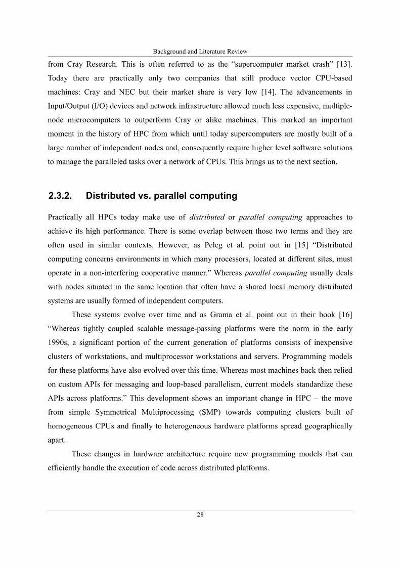
2.3.2. Distributed vs. parallel computing
Practically all HPCs today make use of distributed or parallel computing approaches to
achieve its high performance. There is some overlap between those two terms and they are
often used in similar contexts. However, as Peleg et al. point out in [15] “Distributed
computing concerns environments in which many processors, located at different sites, must
operate in a non-interfering cooperative manner.” Whereas parallel computing usually deals
with nodes situated in the same location that often have a shared local memory distributed
systems are usually formed of independent computers.
These systems evolve over time and as Grama et al. point out in their book [16]
“Whereas tightly coupled scalable message-passing platforms were the norm in the early
1990s, a significant portion of the current generation of platforms consists of inexpensive
clusters of workstations, and multiprocessor workstations and servers. Programming models
for these platforms have also evolved over this time. Whereas most machines back then relied
on custom APIs for messaging and loop-based parallelism, current models standardize these
APIs across platforms.” This development shows an important change in HPC – the move
from simple Symmetrical Multiprocessing (SMP) towards computing clusters built of
homogeneous CPUs and finally to heterogeneous hardware platforms spread geographically
apart.
These changes in hardware architecture require new programming models that can
efficiently handle the execution of code across distributed platforms.
28
Background and Literature Review
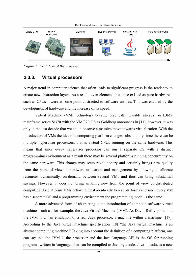
2.3.3. Virtual processors
A major trend in computer science that often leads to significant progress is the tendency to
create new abstraction layers. As a result, even elements that once existed as pure hardware –
such as CPUs – were at some point abstracted to software entities. This was enabled by the
development of hardware and the increase of its speed.
Virtual Machine (VM) technology became practically feasible already on IBM's
mainframe series S/370 with the VM/370 OS as Goldberg announces in [11], however, it was
only in the last decade that we could observe a massive move towards virtualization. With the
introduction of VMs the idea of a computing platform changes substantially since there can be
multiple hypervisor processors, that is virtual CPUs running on the same hardware. This
means that since every hypervisor processor can run a separate OS with a distinct
programming environment as a result there may be several platforms running concurrently on
the same hardware. This change may seem revolutionary and certainly brings new quality
from the point of view of hardware utilization and management by allowing to allocate
resources dynamically, on-demand between several VMs and thus can bring substantial
savings. However, it does not bring anything new from the point of view of distributed
computing. As platforms VMs behave almost identically to real platforms and since every VM
has a separate OS and a programming environment the programming model is the same.
A more advanced form of abstracting is the introduction of complete software virtual
machines such as, for example, the Java Virtual Machine (JVM). As David Reilly points out
the JVM is …“an emulation of a real Java processor, a machine within a machine” [17].
According to the Java virtual machine specification [18] “the Java virtual machine is an
abstract computing machine.” Taking into account the definition of a computing platform, one
can say that the JVM is the processor and the Java language API is the OS for running
programs written in languages that can be compiled to Java bytecode. Java introduces a new
29
Figure 2: Evolution of the processor
Background and Literature Review
level of abstraction and, with its “write once, run anywhere” [19] capability, changes many
programming concepts. However, the Java API as a such is mainly focused on running
bytecode in a single JVM and thus also in this case the programming model is not that
revolutionary from the point of view of distributed computing. These aforementioned
approaches show how the term platform evolved over time. In particular, new abstraction
layers create higher level platforms that can also become hybrids of previous ones. An
example is given by the Java on bare-metal approach described by Hardin [20] and
implemented, for example, in former BEA's product LiquidVM [14]. Despite all this diversity,
none of these platforms substantiates a complete platform for running distributed programs
(metaprograms). The reason is that none of them creates a completely distributed OS that can
handle a distributed programming environment capable of executing metaprograms, that is,
distributed programs written in terms of other programs.
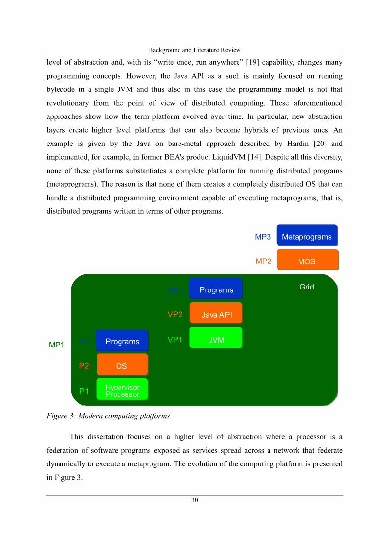
This dissertation focuses on a higher level of abstraction where a processor is a
federation of software programs exposed as services spread across a network that federate
dynamically to execute a metaprogram. The evolution of the computing platform is presented
in Figure 3.
30
Figure 3: Modern computing platforms
Hypervisor Processor
OS
ProgramsP3
P1
P2
JVM
Java API
ProgramsVP3
VP1
VP2
Grid
MOS
MetaprogramsMP3
MP1
MP2
Background and Literature Review
The redefinition of the term “processor” and its evolution require the entity that
controls the processor (the operating system in most cases) to evolve and as a consequence
foster the development of new programming environments.
The next section focuses on state-of-the-art technologies that concentrate on creating a
distributed environment to run programs across a network and thus introduces the concept of
grid computing. Later a critical analysis is provided that shows the conceptual and practical
differences between current grid technologies and the proposed metacomputing approach.
2.4. Grid computing
Grid computing evolved at first as a way to make use of underutilized resources on computers
spread across a network. According to Berman et al. [21] the term Grid was originally used in
analogy to other infrastructure (such as electrical power) grids. “… the analogy correctly
characterizes some aspects of Grid Computing (ubiquity, for example), but not others (the
performance variability of different resources that can support the same code, for example).”
A good comparison and explanation of this analogy is presented by Chetty and Buyya in [22].
Baker et al. [23] present four basic characteristics that define a grid:
• Multiple administrative domains and autonomy. Grid resources are geographically
distributed across multiple administrative domains and owned by different
organizations. The autonomy of resource owners needs to be honored along with their
local resource management and usage policies.
• Heterogeneity. A Grid involves a multiplicity of resources that are heterogeneous in
nature and will encompass a vast range of technologies.
• Scalability. A Grid might grow from a few integrated resources to millions. This raises
the problem of potential performance degradation as the size of Grids increases.
Consequently, applications that require a large number of geographically located
resources must be designed to be latency and bandwidth tolerant.
• Dynamicity or adaptability. In a Grid, resource failure is the rule rather than the
exception. In fact, with so many resources in a Grid, the probability of some resource
failing is high. Resource managers or applications must tailor their behavior
dynamically and use the available resources and services efficiently and effectively.
31
Background and Literature Review
It is important to note that grids are sometimes also referred to as metacomputers or global
computers [14]. It is crucial to take into account that the term metacomputer is differently
understood in this research. The difference should be clearer after the lecture of this chapter.
Looking back at the evolution of grid technologies, one has to mention an important
change that followed the proposal of the Open Grid Service Architecture (OGSA). The OGSA
was introduced in the paper “The physiology of the Grid” by I. Foster , C. Kesselman, J.M.
Nick and S. Tuecke in 2002 [24]. OGSA introduced the notion of a Grid Service, that is, an
extended Web Service [25] with a more specific semantics tailored towards handling state,
persistence and life cycle management. A short overview containing the list of specified
interfaces can be found in the Globus version 3 Tutorial [26].
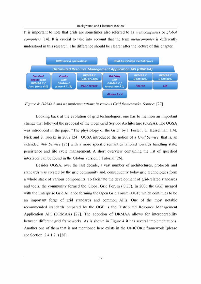
Besides OGSA, over the last decade, a vast number of architectures, protocols and
standards was created by the grid community and, consequently today grid technologies form
a whole stack of various components. To facilitate the development of grid-related standards
and tools, the community formed the Global Grid Forum (GGF). In 2006 the GGF merged
with the Enterprise Grid Alliance forming the Open Grid Forum (OGF) which continues to be
an important forge of grid standards and common APIs. One of the most notable
recommended standards prepared by the OGF is the Distributed Resource Management
Application API (DRMAA) [27]. The adoption of DRMAA allows for interoperability
between different grid frameworks. As is shown in Figure 4 it has several implementations.
Another one of them that is not mentioned here exists in the UNICORE framework (please
see Section 2.4.1.2. ) [28].
32
Figure 4: DRMAA and its implementations in various Grid frameworks. Source: [27]
Background and Literature Review
As the example with the DRMAA implementations shows there are several grid
frameworks, that are widely used and developed worldwide today. Selected ones are
described in greater detail below.
2.4.1. Grid computing technologies
This Section presents five most common grid computing frameworks: the Globus Toolkit, the
UNICORE, the gLite, the Sun Grid Engine and the Legion.
33
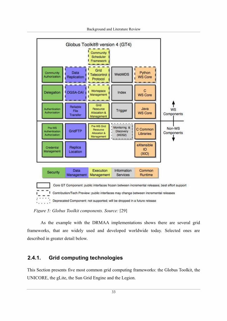
Figure 5: Globus Toolkit components. Source: [29]
Background and Literature Review
2.4.1.1. Globus Toolkit
The Globus Toolkit was the first open source framework that enabled to create grids. The first
stable release (1.0) appeared in 1998. According to Tannenbaum et al. [10] the toolkit includes
software for security, information infrastructure, resource management, data management,
communication, fault detection, and portability. It is packaged as a set of components that can
be used either independently or together to develop applications [29]. Globus focuses on
interoperability and thus defines a set of protocols and common components that form the
Open Grid Service Architecture (OGSA) shown in Figure 5. The details describing the basics
of the toolkit were provided by Foster et al. in papers entitled “The Anatomy of Grid” [30]
and “The Physiology of the Grid” [24]. As Foster et al. describe in [31] “the Globus project is
attacking the metacomputing software problem from the bottom up, by developing basic
mechanisms that can be used to implement a variety of higher-level services.” More details
will be provided later together with an analysis of resource management frameworks in the
Globus Toolkit and, in particular, components such as the Grid Resource Allocation and
Management protocol (GRAM) and the Grid Architecture for Resource Allocation (GARA).
The Globus Toolkit is being developed by companies, organizations and individuals
gathered around the Globus Alliance that was officially created in 2003 to formalize and bring
together developers formerly working on the globus project.
2.4.1.2. UNICORE
UNICORE stands for UNiform Interface to COmputing REsources. It is an open source grid
framework developed and used primarily in Europe. The project was initially funded by the
German Ministry of Education and Research (BMBF) and mainly evolved around the German
Supercomputing Centre, Forschungszentrum Jülich. The initiative was started in 1997 as an
attempt to integrate the infrastructure of German supercomputing centers [32]. Since then
several EU-sponsored projects contributed to the development of UNICORE. One of them,
for example, is the Chemomomentum project that was realized between July 1, 2006 and
December 31, 2008 and coordinated by the Interdisciplinary Centre for Mathematical and
Computational Modelling, from the Warsaw University.
34
Background and Literature Review
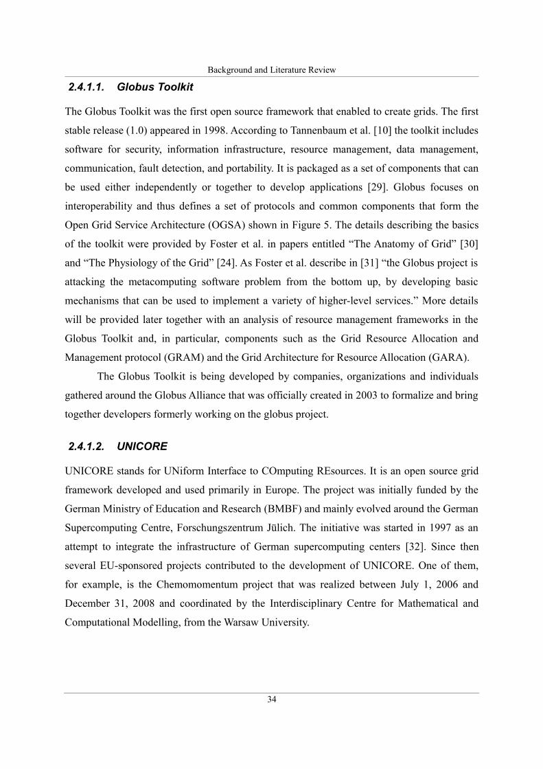
The UNICORE project's website [33] gives a set of characteristics that, as the authors claim,
define UNICORE's unique approach to grid computing.
• Open source under BSD license.
• Standards-based, conforming to the latest standards from the Open Grid Forum
(OGF), W3C, OASIS, and IETF, in particular the Open Grid Services Architecture
(OGSA) and the Web Services Resource Framework (WS-RF 1.2).
• Open and extensible realized with a modern Service- Oriented Architecture (SOA),
which allows to easily replace particular components with others.
• Interoperable with other Grid technologies to enable a coupling of Grid infrastructures
or the users needs
• Seamless, secure, and intuitive following a vertical, end-to-end approach and offering
35
Figure 6: UNICORE architecture. Source: [33]
Background and Literature Review
components at all levels of a modern Grid architecture from intuitive user interfaces
down to the resource level. Like previous versions UNICORE 6 seamlessly integrates
in existing environments.
• Mature security mechanisms adequate for the use in supercomputing environments
and Grid infrastructures. X.509 certificates form the basis for authentication and
authorization, enhanced with a support for proxy certificates and virtual organizations
(VO) based access control.
• Workflow support tightly integrated into the stack while being extensible in order to
use different workflow languages and engines for domain-specific usage.
• Application integration mechanisms on the client, services and resource level for a
tight integration of various types of applications from the scientific and industrial
domain.
• Different clients serving the needs of various scientific communities, e.g. graphical
clients to define complex workflows, command line tool, webbased access.
• Quick and simple to install and configure to address requirements from operational
teams and to lower the barrier of adopting Grid technologies. Similar the configuration
of the various services and components is easy to handle.
• Various operating and batch systems are supported on all layers, i.e. clients, services
and systems; Windows, MacOS, Linux, and Unix systems as well as different batch
systems are supported such as LoadLeveler, Torque, SLURM, LSF, OpenCCS, etc.
• Implemented in Java to achieve platform independence
Despite being a completely separate initiative from the Globus Toolkit as Erwin and Snelling
underline [32]. “...UNICORE does not compete directly with Globus but rather complements
it. Today, the strength of Globus is clearly in providing layers of grid services that enable
developers to build additional layers on top of Globus...” whereas UNICORE can be used to
submit jobs to resources exposed via Globus, for example.
2.4.1.3. gLite
The gLite is a recent service-oriented grid framework developed as part of the EU-sponsored
36
Background and Literature Review
Enabling Grids for E-Science in Europe (EGEE) project that started in 2004. The gLite is a
middleware platform designed from the beginning to support the grid built within and around
the European Centre for Nuclear Research (CERN). As Laure et al. [34] point out, it is
influenced by the requirements of Grid applications, “...the ongoing work in GGF on the
Open Grid Services Architecture (OGSA), as well as previous experience from other Grid
projects such as the EU DataGrid (EDG)2, the LHC Computing Grid (LCG)3, AliEn4,
NorduGrid5, and the Virtual Data Toolkit VDT6 which includes among others Condor7 and
Globus8”.
As Laure et al. explain [35] the gLite Grid services follow a Service Oriented
Architecture which will facilitate interoperability among Grid services and allow easier
compliance with upcoming standards, such as OGSA, that are also based on these principles.
The services are expected to work together in a concerted way in order to achieve the goals of
the end-user, however, they can also be deployed and used independently, allowing their
exploitation in different contexts.
2.4.1.4. Sun Grid Engine
Sun Grid Engine (SGE) is an open source Distributed Resource Manager developed and
maintained by Sun Microsystems. SGE is capable of transparently matching incoming job
requests optimally to available compute cluster resources such as the cpu, the memory, the
I/O, and software licenses. It provides system administrators with the job accounting and
statistics information needed to monitor resource utilization and to determine how to improve
resource allocation [36]. SGE was at first called the Grid Engine and emerged as an
enhancement of CODINE (COmputing in DIstributed Networked Environments) from former
Genias GmbH and Gridware Inc [37] which were acquired by Sun Microsystems in the year
2000. The first version from Sun appeared in the same year and a year later Sun published its
sources and opened the project for development by a wider community of users. Today Sun
Grid Engine is one of the most widely adopted grid resource managers [38].
2 The DataGrid Project, http://www.edg.org3 The LHC Computing Grid, http://cern.ch/lcg4 The AliEn project, http://alien.cern.ch5 The NorduGrid project, http://www.nordugrid.org6 The Virtual Data Toolkit, http://www.cs.wisc.edu/vdt/7 The Condor project, http://www.cs.wisc.edu/condor8 The Globus Alliance, http://www.globus.org
37
Background and Literature Review
2.4.1.5. Legion
Legion is conceptually different from Globus and other grid technologies. It is a metasystem
project that was started at the University of Virginia in 1993. “Its goal is a highly usable,
efficient, and scalable system based on solid computing principles.” [39]. Legion was
designed as an object-oriented Virtual OS that covered individual nodes of the grid. Despite
the differences, later Legion converged towards Globus and introduced the Open Grid Service
Infrastructure (OGSI) that was developed primarily within the Globus community.
Despite representing a metasystem approach Legion cannot be treated as a federated
metacomputing environment such as SORCER. The reason is that it did not define the
concept of metaprogramming and, consequently programs executed in Legion are written for
single OS environments and the scheduler is used to place the code on the appropriate node.
These characteristics are expressed in [40], for example: “The key element in resource
management is placement, i.e., determining on which machine to start running an object. In
Legion, placement is a negotiation process between the requirements of users and the policies
of resource managers.”
2.4.2. Critical discussion on grid computing
As the given examples show, grid computing is a relatively widely adopted and well
established technology that introduced a significant number of architectures, standards and
protocols. However, despite the immense diversity among different grid technologies, there
are some general shortcomings that apply to most solutions.
One of the most important deficiencies is the complexity of the available architectures
and solutions that make them difficult to deploy and manage. As Stockinger noticed “...the
Grid should use simple concepts that many people can understand. The system’s complexity
must be hidden by easy-to-use tools, interfaces, and high-level applications” [41]. Another
important aspect is the lack of stability that may result from the fact that grids emerged as a
technology made for scientists by scientists and despite being around for more than a decade
they still lie primarily within the domain of science. Stockinger underscores this problem by
criticizing the most widely adopted grid framework “...projects such as the Globus Alliance
provide the most widely known Grid middleware toolkit. However, for several years it has
38
Background and Literature Review
been in a transition phase, so it’s neither 100 percent stable nor completely ready for intensive
production use” [41].
To cope with the aforementioned problems of complexity and instability, the grid
community introduced OGSA and the notion of a grid service. The focus on web service-
based technology within the grid community helped to solve many interoperability issues,
however, since the standards are still evolving this continues to be a source of confusion and
incompatibility. A good example is the Open Grid Services Infrastructure (OGSI) that was
introduced in 2003 to add stateful web services [42], however, it was later replaced by the
Web Services Resource Framework (WSRF) that became an OASIS-accepted standard in
2006 [43]. Currently the Globus Toolkit migrates back to using a pure web service approach
and the WSRF instead of OGSI [44].
The introduction of grid/web services into the stack of grid technologies allowed for
solving some integration issues by standardizing the communication protocol in the form of
XML and SOAP [45]. However, as Sobolewski points out [46], [47] the “one size fits all”
approach is not always the best choice, especially in the case of scientific applications where
often vast amounts of data must be exchanged between services and, converting them to the
XML format and later parsing the received message, adds a lot of overhead.
Another important issue with current grid technologies involves their architecture in
two aspects. The first one refers to the use of grid/web services. One of the baselines of the
Service Oriented paradigm is the use of a service registry (Universal Description Discovery
and Integration (UDDI) [48]) to allow for dynamic late binding of service providers at
runtime. However, as practice has proved the use of the UDDI may often significantly impair
performance and therefore, the registry is often omitted and replaced by a static configuration
based on a directly exchanged WSDL file [25]. This situation may often lead to the
introduction of a single point of failure and, consequently in this case, the service oriented
architecture becomes a client-server architecture, in practice.
The second architectural issue is bound to the fact that, despite the use of networks of
compute nodes within grids, the programming methods have not changed significantly
enough. As a result, most applications are still written for use on a single computer and grid
schedulers are used to move executable code to currently available hosts. As Sobolewski
points out in [2] this approach “...is reminiscent of batch processing in the era when operating
systems were not yet developed. A series of programs ("jobs") is executed on a computer
39
Background and Literature Review
without human interaction or the possibility to view any results before the execution is
complete.”
To conclude this discussion let us enumerate the most important issues that most
current grid solutions encounter: high complexity, instability, potential single point-of-failure
due to static configuration and impaired performance as a result of using XML and SOAP.
The next section introduces the federated metacomputing approach followed in this
research and shows how these issues are addressed in the architecture of a Federated
Metacomputing Environment.
2.5. Metacomputing
Before presenting the details of the federated metacomputing approach, it is necessary to
review and discuss the literature regarding the concept of metacomputing. This term was
introduced a long time ago and in the meantime it was often used to describe other distributed
computing concepts, including some of the above criticized, traditional grid technologies.
According to the National Center for Supercomputing Applications (NCSA) a
metacomputer is “...a collection of computers held together by state-of-the-art technology and
"balanced" so that, to the individual user, it looks and acts like a single computer” [49]. This
term was at first introduced by the NCSA around 1992 to describe a software that would
allow us to divide programs into smaller components that could be executed in parallel on
three different high performance computer clusters [50]. The aforementioned definition is
very broad and therefore, it overlaps with the concept of grid computing. In fact, as some
examples later in this section show, historically the term metacomputing was used to describe
the predecessors of grids. Consequently, it is important to make a clear distinction between
those two approaches.
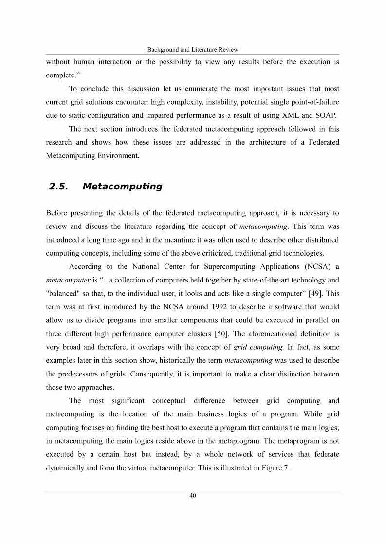
The most significant conceptual difference between grid computing and
metacomputing is the location of the main business logics of a program. While grid
computing focuses on finding the best host to execute a program that contains the main logics,
in metacomputing the main logics reside above in the metaprogram. The metaprogram is not
executed by a certain host but instead, by a whole network of services that federate
dynamically and form the virtual metacomputer. This is illustrated in Figure 7.
40
Background and Literature Review
Another important difference refers to the architecture, discovery of services and
binding. As was described in the previous section, while grids are de facto built using client-
server architecture, the federated metacomputing is a true peer-to-peer service-to-service
environment where all service providers are located using dynamic zero-configuration
discovery/join techniques.
Such an environment consists of loosely coupled service providers that form the
service grid. At execution time these providers federate dynamically to create an execution
environment for metaprograms and thus form the virtual metacomputer. These metaprograms
consist of instructions defined in terms of individual services, that is, every instruction of the
metaprogram represents a call to a service provider that runs on one of the nodes within the
environment.
A single computer OS handles certain features such as security, storage (file systems),
resource allocation and management etc. at the system level (using services or “deamons” in
Unix, for example). Similarly, the metacomputing environment offers these functions at the
level of the whole metacomputer in form of decentralized system services that handle security
across all providers, distributed storage (distributed file system, for example: [51]) and
services that coordinate the execution of complex metaprograms across the network.
Looking at the metacomputing environment as a metaoperating system, it should be
noticed that an important part of the contribution of this research lies in the conceptual
definition of system services related to resource management. Those services enable the
configuration and management of resources of a virtual metacomputer and, consequently
allow the virtual metaprocessor to be configured to run metaprograms efficiently and
41
Figure 7: Business logics in grid computing vs. metacomputing
Background and Literature Review
according to their QoS requirements.
Taking into account the previous critical view of grid technologies and this platform
level approach, it should be noted that current grid technologies should be regarded as batch
schedulers that move executable code around a network of statically connected compute
nodes. They perform these high level system functions in a centralized manner. In contrast, in
a metacomputing environment all resources are treated together in a dynamic, decentralized
way.
A detailed comparison of those two approaches to distributed computing is presented
in Table 1.
Table 1: Grid computing vs. federated metacomputing
Grid Computing Federated Metacomputing
Architecture Centralized/Client Server Peer-2-Peer (Service-2-Service)
Task
scheduling
Schedulers and queues No schedulers or queues - resources are
assigned dynamically at runtime from all
available providers in the network
Managed by Central resource manager
/scheduler
Decentralized coordinating service
invoked per request (many instances
may operate simultaneously)
Configuration Static using DNS or IP addresses Dynamic using discovery/join protocols
Remote
invocation
RPC over web services/SOAP Federated Method Invocation –
executing metaprograms
Until around 1998 when the term grid computing became widely recognized, the term
metacomputing was used to describe all kinds of grid related technologies and their
predecessors. For example, Czajkowski et al. who later became the founders of the grid
community and the globus project, published a paper entitled “A resource management
architecture for metacomputing systems” [52]. Despite its title, this paper discusses issues
related to Network-Batch Queuing and the predecessors of grid resource managers. Some
other papers, in particular: [53], [54] and [55] that use the term metacomputing also refer to
technologies bound to traditional grids.
Notable examples of metacomputing environments that propose similar architectural
qualities as the approach followed in this research were described by Sunderam and
42
Background and Literature Review
Kurzyniec [56], Gehring et al. [57], [58] and Johasz et al. [59], [60].
The first approach described in the paper entitled: “Lightweight self-organizing
frameworks for metacomputing” [56] describes an architecture for a distributed system called
H2O that introduces some similar concepts as the SORCER environment presented in this
research. In particular, H2O defines a common execution context – a unified object-oriented
structure used to pass input and output parameters to services and proposes a unified interface
to be implemented by all services called pluglet. However, H2O as described in the mentioned
paper, uses plain RMI and Web Services for the binding of services and thus, as explained in
Section 2.6.1. , lacks the reliability and dynamic aspects offered by the binding architecture
of SORCER. This flaw was later addressed by Gorissen et al. who propose in the paper
entitled “H2O Metacomputing – Jini Lookup and Discovery” [61] to use the Jini architecture
in H2O.
A similar approach was followed by Pota and Juhasz who proposed a dynamic grid
environment called JGrid that was also based on Jini. In contrast, Gehring et al. developed an
architecture of a metacomputer based on the proposed MOL-kernel component where the
communication is realized in a decentralized, reliable way using custom protocols.
The aforementioned projects, however, interesting and similar in their assumptions to
the SORCER project, were never developed that far as to create a complete MOS. In
particular, the literature shows no evidence of tackling the problem of SLA-based resource
management within these projects.
The next section presents the SORCER metacomputing platform, including
technologies that enable dynamic binding of services that form the virtual metacomputer, the
metaprogramming concept and basic components of the SORCER Metacompute OS.
2.6. The metacomputing platform
The following subsections shortly describe the elements of the metacomputing environment
(see Figure 10) and, in particular, focus on the motivation, basic networking layer,
architecture and the exertion-oriented programming concepts accordingly.
43
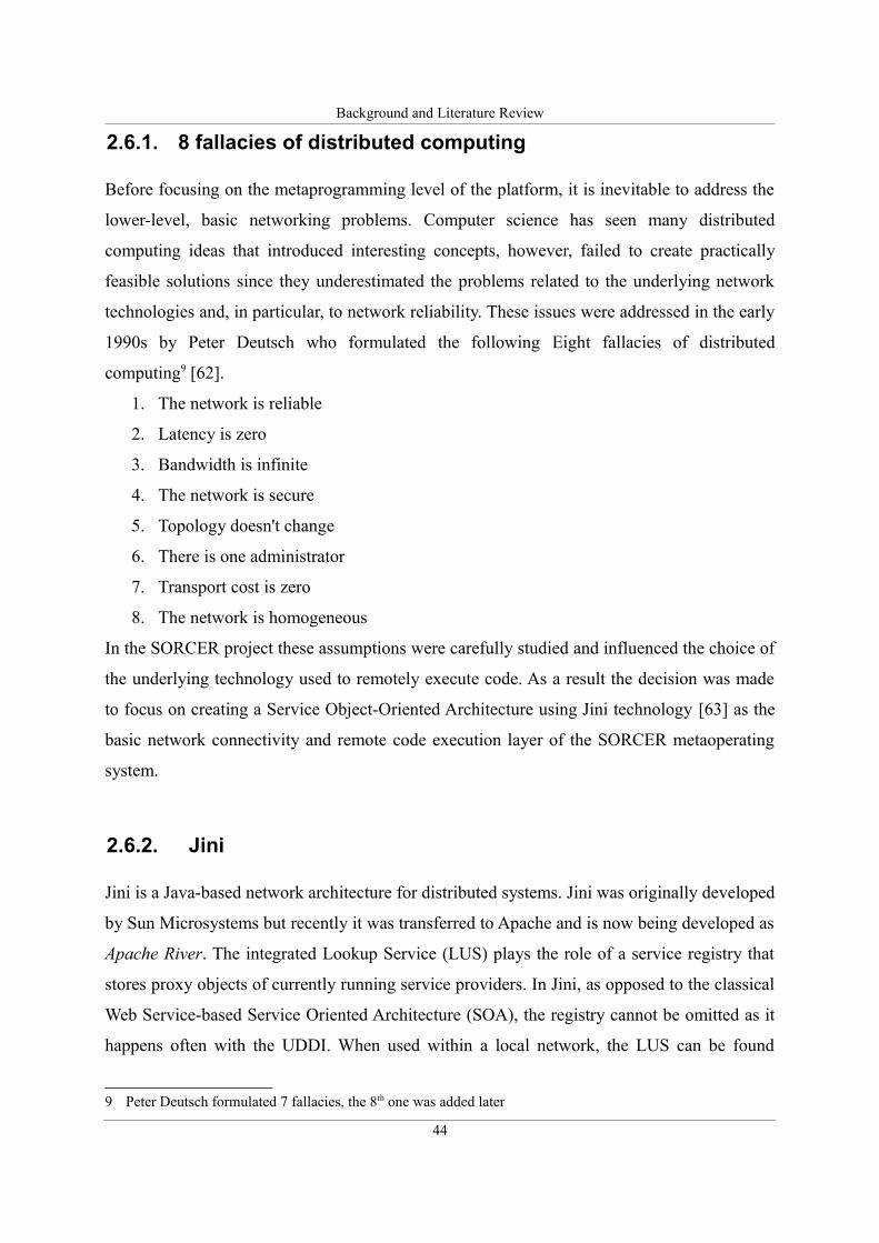
Background and Literature Review
2.6.1. 8 fallacies of distributed computing
Before focusing on the metaprogramming level of the platform, it is inevitable to address the
lower-level, basic networking problems. Computer science has seen many distributed
computing ideas that introduced interesting concepts, however, failed to create practically
feasible solutions since they underestimated the problems related to the underlying network
technologies and, in particular, to network reliability. These issues were addressed in the early
1990s by Peter Deutsch who formulated the following Eight fallacies of distributed
computing9 [62].
1. The network is reliable
2. Latency is zero
3. Bandwidth is infinite
4. The network is secure
5. Topology doesn't change
6. There is one administrator
7. Transport cost is zero
8. The network is homogeneous
In the SORCER project these assumptions were carefully studied and influenced the choice of
the underlying technology used to remotely execute code. As a result the decision was made
to focus on creating a Service Object-Oriented Architecture using Jini technology [63] as the
basic network connectivity and remote code execution layer of the SORCER metaoperating
system.
2.6.2. Jini
Jini is a Java-based network architecture for distributed systems. Jini was originally developed
by Sun Microsystems but recently it was transferred to Apache and is now being developed as
Apache River. The integrated Lookup Service (LUS) plays the role of a service registry that
stores proxy objects of currently running service providers. In Jini, as opposed to the classical
Web Service-based Service Oriented Architecture (SOA), the registry cannot be omitted as it
happens often with the UDDI. When used within a local network, the LUS can be found
9 Peter Deutsch formulated 7 fallacies, the 8th one was added later
44
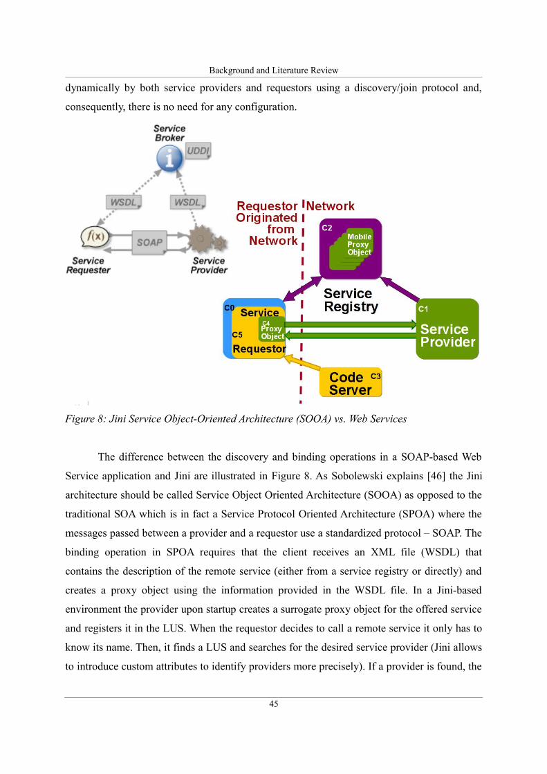
Background and Literature Review
dynamically by both service providers and requestors using a discovery/join protocol and,
consequently, there is no need for any configuration.
The difference between the discovery and binding operations in a SOAP-based Web
Service application and Jini are illustrated in Figure 8. As Sobolewski explains [46] the Jini
architecture should be called Service Object Oriented Architecture (SOOA) as opposed to the
traditional SOA which is in fact a Service Protocol Oriented Architecture (SPOA) where the
messages passed between a provider and a requestor use a standardized protocol – SOAP. The
binding operation in SPOA requires that the client receives an XML file (WSDL) that
contains the description of the remote service (either from a service registry or directly) and
creates a proxy object using the information provided in the WSDL file. In a Jini-based
environment the provider upon startup creates a surrogate proxy object for the offered service
and registers it in the LUS. When the requestor decides to call a remote service it only has to
know its name. Then, it finds a LUS and searches for the desired service provider (Jini allows
to introduce custom attributes to identify providers more precisely). If a provider is found, the
45
Figure 8: Jini Service Object-Oriented Architecture (SOOA) vs. Web Services
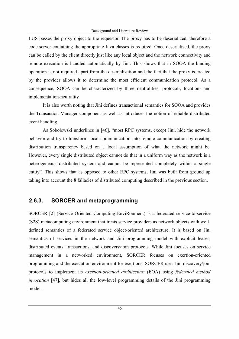
Background and Literature Review
LUS passes the proxy object to the requestor. The proxy has to be deserialized, therefore a
code server containing the appropriate Java classes is required. Once deserialized, the proxy
can be called by the client directly just like any local object and the network connectivity and
remote execution is handled automatically by Jini. This shows that in SOOA the binding
operation is not required apart from the deserialization and the fact that the proxy is created
by the provider allows it to determine the most efficient communication protocol. As a
consequence, SOOA can be characterized by three neutralities: protocol-, location- and
implementation-neutrality.
It is also worth noting that Jini defines transactional semantics for SOOA and provides
the Transaction Manager component as well as introduces the notion of reliable distributed
event handling.
As Sobolewski underlines in [46], “most RPC systems, except Jini, hide the network
behavior and try to transform local communication into remote communication by creating
distribution transparency based on a local assumption of what the network might be.
However, every single distributed object cannot do that in a uniform way as the network is a
heterogeneous distributed system and cannot be represented completely within a single
entity”. This shows that as opposed to other RPC systems, Jini was built from ground up
taking into account the 8 fallacies of distributed computing described in the previous section.
2.6.3. SORCER and metaprogramming
SORCER [2] (Service Oriented Computing EnviRonment) is a federated service-to-service
(S2S) metacomputing environment that treats service providers as network objects with well-
defined semantics of a federated service object-oriented architecture. It is based on Jini
semantics of services in the network and Jini programming model with explicit leases,
distributed events, transactions, and discovery/join protocols. While Jini focuses on service
management in a networked environment, SORCER focuses on exertion-oriented
programming and the execution environment for exertions. SORCER uses Jini discovery/join
protocols to implement its exertion-oriented architecture (EOA) using federated method
invocation [47], but hides all the low-level programming details of the Jini programming
model.
46
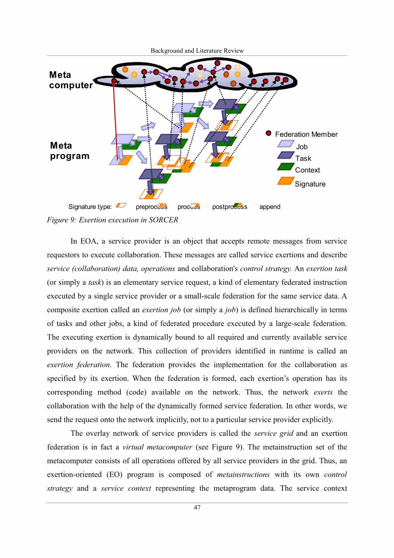
Background and Literature Review
In EOA, a service provider is an object that accepts remote messages from service
requestors to execute collaboration. These messages are called service exertions and describe
service (collaboration) data, operations and collaboration's control strategy. An exertion task
(or simply a task) is an elementary service request, a kind of elementary federated instruction
executed by a single service provider or a small-scale federation for the same service data. A
composite exertion called an exertion job (or simply a job) is defined hierarchically in terms
of tasks and other jobs, a kind of federated procedure executed by a large-scale federation.
The executing exertion is dynamically bound to all required and currently available service
providers on the network. This collection of providers identified in runtime is called an
exertion federation. The federation provides the implementation for the collaboration as
specified by its exertion. When the federation is formed, each exertion’s operation has its
corresponding method (code) available on the network. Thus, the network exerts the
collaboration with the help of the dynamically formed service federation. In other words, we
send the request onto the network implicitly, not to a particular service provider explicitly.
The overlay network of service providers is called the service grid and an exertion
federation is in fact a virtual metacomputer (see Figure 9). The metainstruction set of the
metacomputer consists of all operations offered by all service providers in the grid. Thus, an
exertion-oriented (EO) program is composed of metainstructions with its own control
strategy and a service context representing the metaprogram data. The service context
47
Figure 9: Exertion execution in SORCER
Federation Member
Job
Task
Context
Signature
Signature type: preprocess process postprocess append
Metacomputer
Metaprogram
Background and Literature Review
describes the collaboration data that tasks and jobs work on. Each service provider offers
services to other service peers on the object-oriented overlay network. These services are
exposed indirectly by operations in well-known public remote interfaces and considered to be
elementary (tasks) or compound (jobs) activities in EOA. Indirectly means here, that you
cannot invoke any operation defined in provider’s interface directly. These operations can be
specified in the requestor’s exertion only, and the exertion is passed by itself on to the relevant
service provider via the top-level Servicer interface implemented by all service providers
called servicers—service peers. Thus all service providers in EOA implement the
service(Exertion, Transaction):Exertion operation of the Servicer interface.
When the servicer accepts its received exertion, then the exertion’s operations can be invoked
by the servicer itself, if the requestor is authorized to do so. Servicers do not have mutual
associations prior to the execution of an exertion; they come together dynamically (federate)
for a collaboration as defined by its exertion. In EOA requestors do not have to lookup for any
network provider at all, they can submit an exertion, onto the network by calling
Exertion.exert(Transaction):Exertion on the exertion. The exert operation will
create a required federation that will run the collaboration as specified in the EO program and
return the resulting exertion back to the exerting requestor. Since an exertion encapsulates
everything needed (data, operations, and control strategy) for the collaboration, all results of
the execution can be found in the returned exertion’s service contexts.
Domain specific servicers within the federation, or task peers (taskers), execute task
exertions. Rendezvous peers (jobbers and spacers) coordinate execution of job exertions.
Providers of the Taker, Jobber, and Spacer type are three of SORCER main
infrastructure servicers-see Figure 9. In view of the P2P architecture defined by the
Servicer interface, a job can be sent to any servicer. A peer that is not a Jobber type is
responsible for forwarding the job to one of available rendezvous peers in the SORCER
environment and returning results to the requestor.
Thus implicitly, any peer can handle any job or task. Once the exertion execution is
complete, the federation dissolves and the providers disperse to seek other collaborations to
join. Also, SORCER supports a traditional approach to grid computing similar to those found,
for example in Condor [64]. Here, instead of exertions being executed by services providing
business logic for invoked exertions, the business logic comes from the service requestor's
executable codes that seek compute resources on the network.
48
Background and Literature Review
Grid-based services in the SORCER environment include Grider services
collaborating with Jobber and Spacer services for traditional grid job submission. Caller
and Methoder services are used for task execution. Callers execute conventional programs
via a system call as described in the service context of the submitted task. Methoders can
download required Java code (task method) from requestors to process any submitted context
accordingly with the code downloaded. In either case, the business logic comes from
requestors; it is a conventional executable code invoked by Callers with the standard
Caller’s service context, or mobile Java code executed by Methoders with a matching
service context provided by the requestor.
2.6.4. Service messaging and exertions
In object-oriented terminology, a message is the single means of passing control to an object.
If the object responds to the message, it has an operation and its implementation (method) for
that message. Because object data is encapsulated and not directly accessible, a message is the
only way to send data from one object to another. Each message specifies the name
(identifier) of the receiving object, the name of operation to be invoked, and its parameters. In
the unreliable network of objects; the receiving object might not be present or can go away at
any time. Thus, we should postpone receiving object identification as late as possible.
Grouping related messages per one request for the same data set makes a lot of sense due to
network invocation latency and common errors in handling. These observations lead us to
service-oriented messages called exertions. An exertion encapsulates multiple service
signatures that define operations, a service context that defines data, and a control strategy
that defines how signature operations flow in collaboration. In SERVME a signature includes
a QoS Context (defined in Section 4.3.1) that encapsulates all QoS/SLA data. Different types
of control exertions (IfExertion, ForExertion, and WhileExertion) can be used to
define flow of control that can also be configured additionally with adequate signature
attributes [47].
An exertion can be invoked by calling exertion’s exert operation:
Exertion.exert(Transaction):Exertion, where a parameter of the Transaction
type is required when the transactional semantics is needed for all participating nested
49
Background and Literature Review
exertions within the parent one, otherwise can be null. Thus, EO programming allows us to
submit an exertion onto the network and to perform executions of exertion’s signatures on
various service providers indirectly, but where does the service-to-service communication
come into play? How do these services communicate with one another if they are all
different? Top-level communication between services, or the sending of service requests
(exertions), is done through the use of the generic Servicer interface and the operation
service that all SORCER services are required to provide—
Servicer.service(Exertion, Transaction). This top-level service operation takes
an exertion as an argument and gives back an exertion as the return value. How this operation
is used in the federated method invocation framework is described in detail in [47].
So why are exertions used rather than directly calling on a provider's method and
passing service contexts? There are two basic answers to this. First, passing exertions helps to
aid with the network-centric messaging. A service requestor can send an exertion out onto the
network—Exertion.exert()—and any servicer can pick it up. The servicer can then look
at the interface and PROCESS operation requested within the exertion, and if it doesn't
implement the desired interface or provide the desired operation, it can continue forwarding it
to another provider who can service it. Second, passing exertions helps with fault detection
and recovery, and security. Each exertion has its own completion state associated with it to
specify who is invoking it, if it has yet to run, has already completed, or has failed. Since full
exertions are both passed and returned, the requestor can view the failed exertion composition
to see what method was being called as well as what was used in the service context input
nodes that may have caused the problem. Since exertions provide all the information needed
to execute a task including its control strategy, a requestor would be able to pause a job
between tasks, analyze it and make needed updates. To figure out where to resume a job, a
rendezvous service would simply have to look at the task’s completion states and resume the
first one that wasn't completed yet.
The described programming environment is integrated into the metacomputing
platform presented in the next section.
2.6.5. SORCER metacomputing platform
All layers and components that form the SORCER platform are shown in Figure 10. As was
50
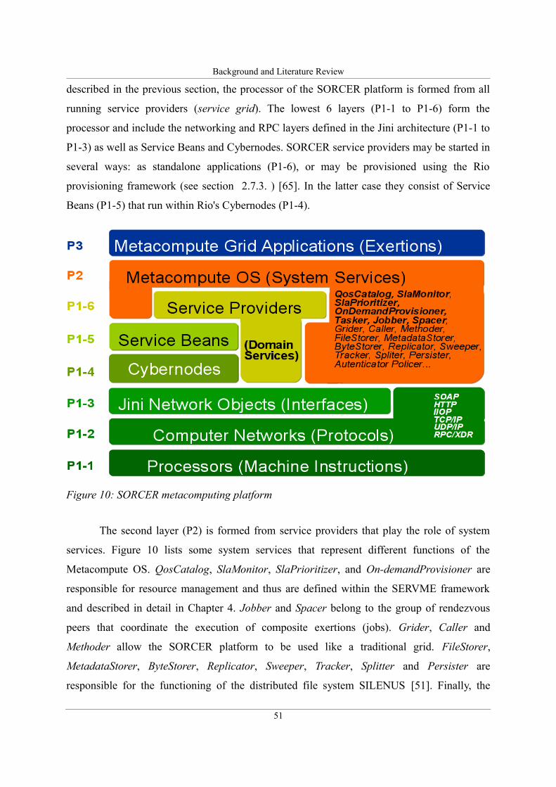
Background and Literature Review
described in the previous section, the processor of the SORCER platform is formed from all
running service providers (service grid). The lowest 6 layers (P1-1 to P1-6) form the
processor and include the networking and RPC layers defined in the Jini architecture (P1-1 to
P1-3) as well as Service Beans and Cybernodes. SORCER service providers may be started in
several ways: as standalone applications (P1-6), or may be provisioned using the Rio
provisioning framework (see section 2.7.3. ) [65]. In the latter case they consist of Service
Beans (P1-5) that run within Rio's Cybernodes (P1-4).
The second layer (P2) is formed from service providers that play the role of system
services. Figure 10 lists some system services that represent different functions of the
Metacompute OS. QosCatalog, SlaMonitor, SlaPrioritizer, and On-demandProvisioner are
responsible for resource management and thus are defined within the SERVME framework
and described in detail in Chapter 4. Jobber and Spacer belong to the group of rendezvous
peers that coordinate the execution of composite exertions (jobs). Grider, Caller and
Methoder allow the SORCER platform to be used like a traditional grid. FileStorer,
MetadataStorer, ByteStorer, Replicator, Sweeper, Tracker, Splitter and Persister are
responsible for the functioning of the distributed file system SILENUS [51]. Finally, the
51
Figure 10: SORCER metacomputing platform
Background and Literature Review
Authenticater and Policer handle access and security within SORCER. The last, top layer (P3)
of the platform belongs to metaprograms (exertions).
2.7. Resource management in distributed computing
Resource management is an important aspect of distributed computing. Much research has
been done in the area of the Service Level Agreements (SLA) management of services. One of
the first attempts to apply QoS to services rather than low-level network protocols were
pursued in the area of grid computing.
Grid computing introduced the Grid resource management that Nabrzyski et al. in [66]
define as “...the process of identifying requirements, matching resources to applications,
allocating those resources, and scheduling and monitoring Grid resources over time in order
to run Grid applications as efficiently as possible. Grid applications compete for resources
that are very different in nature, including processors, data, scientific instruments, networks,
and other services. Complicating this situation is the general lack of data available about the
current system and the competing needs of users, resource owners, and administrators of the
system.”
The same problems are described differently in [67] by Foster and Kesselmann: “In
traditional computing systems, resource management is a well-studied problem. Resource
managers such as batch schedulers, workflow engines, and operating systems exist for many
computing environments. These resource management systems are designed and operate
under the assumption that they have complete control of a resource and thus can implement
the mechanisms and policies needed for effective use of that resource in isolation.
Unfortunately, this assumption does not apply to the Grid. We must develop methods for
managing Grid resources across separately administered domains, with the resource
heterogeneity, lose of absolute control, and inevitable differences in policy that result.”
One of the first known implementations of the grid resource management can be found
in [68], where Czajkowski et al. present the Globus Resource Allocation Manager (GRAM).
Together with the local resource managers (GRAM) authors propose a Resource Specification
Language (RSL) that is used to describe resources and QoS requirements. As Czajkowski et
al. mention in [68], GRAM mechanisms were used by David Abramson and Jonathan Giddy
to develop Nimrod-G, a wide-area version of the Nimrod [69] tool that automates the creation
52
Background and Literature Review
and management of large parametric experiments. The next step was made by defining the
Globus Architecture for Reservation and Allocation (GARA) in [70] and [71]. Several
extensions were proposed, for example, to support Advanced Reservations and Co-Allocation.
[72]. Further work challenged the problem of complex, multi-level SLA management and led
to the development of a generic Service Negotiation and Acquisition Protocol (SNAP) [73].
An example project that implements the SNAP protocol can be found in [74]. In [75] authors
present a modification of GRAM architecture that incorporates the use of the SNAP protocol
to perform SLA management.
As grid technology started to move from traditional network batch queuing towards
the application of Web Services (WS) as a communication protocol, the research of the grid
community, as well as others, concentrated on integrating the SLA management into the
standard stack of WS. The grid community developed the Open Grid Service Architecture
(OGSA) [76] which stated the need to address the SLA management in grids based on WS.
Apart from the developments of the Globus community, there were also many attempts
to apply agent technology to resource management within grids. For example, Kumar et al.
[77] concentrated on interactive grids in which agent technology was used for monitoring
purposes and Shen and Li proposed in [78] to create agent-based grids.
Another research area, especially relevant to ours, is described in [79] and [80], where
authors focus on resource discovery in distributed systems and confront traditional grids with
P2P environments. The presented characteristics of P2P architectures, i.a. the problem of low
reliability of resources, and the dynamic nature of the network are especially relevant to our
research. Addressing these issues was one of the key goals of the SORCER project and
SERVME provides an improvement in this respect by allowing to better allocate and optimize
resources.
The SERVME framework concentrates on federated, distributed environments.
Although, there were several projects that claimed to address the SLA management in
federated environments [81], [82], [83], none of them referred to a federation of services
specified and created on-the-fly such as the one which exists in the exertion-oriented
architecture utilized by SERVME. Most aforementioned projects use the term federation to
underline the organizational challenges that arise due to the fact that a federated system is
usually composed of static services that belong to different administrative entities.
53
Background and Literature Review
2.7.1. QoS/SLA model
One of the key elements of resource management is the ability to describe resource
capabilities and express QoS requirements This requires that SLA specification languages be
introduced. Some general architectural approaches can be observed that are usually taken to
define an SLA specification.
The most common approach uses mathematical formalization or creates a specific
language to define QoS and SLAs. One of the examples is [81] where the authors propose a
specification language, similar to C, called Contract Definition Language (CDL), another one,
presented in [84] and [85] is an object oriented language: QoS Modeling Language (QML). A
slightly different approach is taken by C. Yang et al [86] who suggest to specify QoS
requirements in the natural language and then convert them to UML or high level
programming languages. A general overview and a comparison of many SLA specification
languages is provided in [87] by J.Jingwen and K. Nahrstedt.
Another group of specifications that mostly concentrates on defining SLAs for WS,
creates an XML schema and use XML as the representation of QoS parameters and SLAs.
Most notable of them are the Web Service Level Agreement framework (WSLA) [88] [89]
and the WS-Agreement specification [90]. The latter, however, has a very limited ability to
specify conditional expressions and alternatives. Therefore, extensions have been proposed in
the CoreGRID project [91], [92] for example. Recently the developments within the
NextGRID project introduce new QoS parameters such as i.a. Robustness and Resilience [93].
Apart from agreed standards, such as the above, there are also a number of custom solutions.
For example, the WS-QoS framework [94] that, in contrast, proposes to specify QoS
parameters and provision prices in the WS protocol stack within the WSDL specification [25].
The most recent tendency is to use ontologies to specify SLAs [95], [96], [97].
All the above mentioned solutions propose a kind of mathematical formalism or
specific language semantics to describe QoS parameters and SLAs. The approach taken in this
research and described in Section 4.3. follows a different path and focuses on defining an
object-oriented model in terms of communication interfaces as abstract data types. Although
the reference implementation is realized in Java the APIs are modeled generally to allow it to
be utilized in any modern object-oriented language. The proposed SLA model provides an
open framework that can be extended and implemented to meet the requirements of custom
54
Background and Literature Review
environments. In my opinion this approach offers greater flexibility than i.e. using XML while
preserving a richer and simpler degree of expressiveness. It also allows for a more direct and
more efficient implementation than i.e. using ontologies by eliminating the laborious
intermediary conversion steps.
2.7.2. SLA negotiation
SLA negotiation has been researched extensively at first in the area of networking. Its
application to services was propagated with the emergence of grid computing. At first the
GRAM [68] lacked a general negotiation protocol that was added later (as described in [75])
in the form of the Service Negotiation and Acquisition Protocol (SNAP) [73]. SNAP
addresses complex, multi-level SLA management and defines three types of SLAs: Task
SLAs, Resource SLAs and Binding SLAs. It also provides a generic framework, however as
Quan and Kao [98] underline the protocol needs further extensions for its implementation to
address specific problems.
When grid technology started to move from traditional network batch queuing towards
the application of Web Services (WS), the work of the grid community, as well as others,
focused on incorporating the SLA negotiation into the stack of WS technologies. As
mentioned previously, the WSLA and the WS-Agreement specifications were proposed to
standardize the SLA specification. WS-Agreement also provides basic negotiation semantics,
however, permits only simple one-phase – offer-accept/reject negotiations. More complex
two- and three-phase commit protocols applied in conjunction with WS-Agreement are
described in [91],[78]. Ouelhadj et al. in [99] propose to use agents for the negotiation of
SLAs in grids. In [100] authors propose to introduce a meta-negotiation protocol that will
allow the parties to select via negotiation the protocol used for the actual SLA negotiation.
The aforementioned solutions concentrate on traditional grids or WS architectures,
however, new challenges that reach beyond the multi-phase commit protocols arise when
introducing P2P resource management. Much work has also been pursued in this area, for
example by Iyer et al. in [101] and Cao et al. [80], however, this research does not include the
SLA negotiation.
To the best of my knowledge this research presents the first approach to SLA
management and negotiation for distributed environments where federations of services are
55
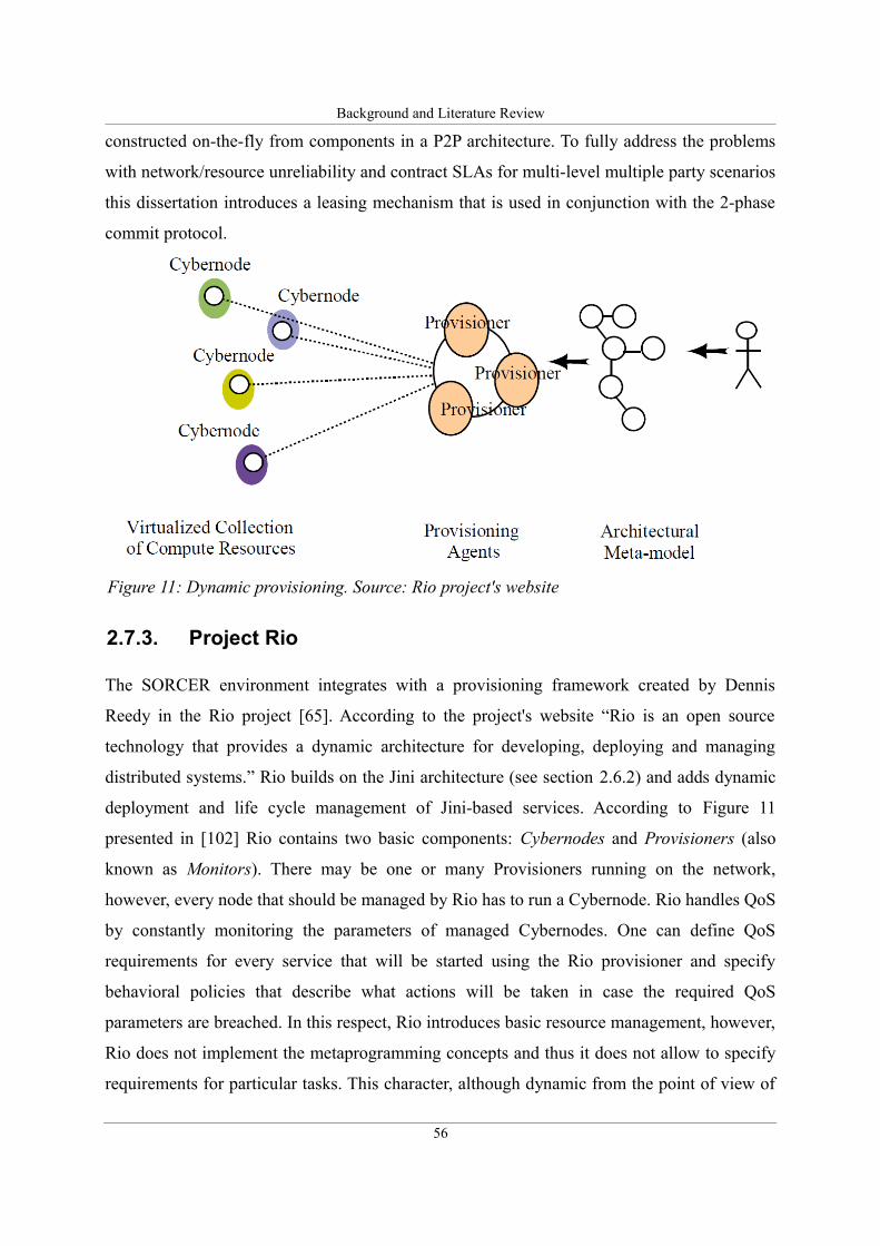
Background and Literature Review
constructed on-the-fly from components in a P2P architecture. To fully address the problems
with network/resource unreliability and contract SLAs for multi-level multiple party scenarios
this dissertation introduces a leasing mechanism that is used in conjunction with the 2-phase
commit protocol.
2.7.3. Project Rio
The SORCER environment integrates with a provisioning framework created by Dennis
Reedy in the Rio project [65]. According to the project's website “Rio is an open source
technology that provides a dynamic architecture for developing, deploying and managing
distributed systems.” Rio builds on the Jini architecture (see section 2.6.2) and adds dynamic
deployment and life cycle management of Jini-based services. According to Figure 11
presented in [102] Rio contains two basic components: Cybernodes and Provisioners (also
known as Monitors). There may be one or many Provisioners running on the network,
however, every node that should be managed by Rio has to run a Cybernode. Rio handles QoS
by constantly monitoring the parameters of managed Cybernodes. One can define QoS
requirements for every service that will be started using the Rio provisioner and specify
behavioral policies that describe what actions will be taken in case the required QoS
parameters are breached. In this respect, Rio introduces basic resource management, however,
Rio does not implement the metaprogramming concepts and thus it does not allow to specify
requirements for particular tasks. This character, although dynamic from the point of view of
56
Figure 11: Dynamic provisioning. Source: Rio project's website
Background and Literature Review
behavior (active policies allow notification, relocation etc.), is static otherwise as it is
independent of the currently executed tasks (exertions in SORCER). This explains why this
approach to resource management is not sufficient and a framework such as the one presented
in this research is required to handle QoS and allow to negotiate and sign SLAs for particular
exertions.
The current reference implementation of SERVME described in Chapter 5 uses Rio as
the source of current QoS parameters as well as to perform on-demand provisioning of
services.
2.8. Optimal resource allocation and management
The goal of this dissertation is defined as the optimal resource allocation in federated
metacomputing environments. Therefore, it is important to define how this optimality is
understood. Webster's Online dictionary defines “optimal” as “most desirable, satisfactory:
optimum” [103]. As a result, the “optimal resource allocation” is defined in this dissertation
as the “most satisfactory resource allocation for a given program as specified by its QoS and
guaranteed by SLA of the underlying operating system.” This optimality of resource
allocation may be regarded in two aspects. It may be understood quantitatively in a formal
way as reaching a certain minimum or maximum as well as qualitatively as achieving a
satisfactory solution. The optimality of resource allocation defined in this dissertation
represents both aspects of this definition.
Operating systems such as UNIX, for example, distinguish two programming
environments. Programs may be written in low level languages that target particular CPU
instructions or they may be interpreted by the OS itself. The actual language of the OS is the
shell script. Exertion-oriented programs can be compared to network shell scripts that are
intended to be executed by a network of services and not by any particular node. In their case,
the CPU instructions are represented by service providers. This dissertation presents a system
approach and focuses on creating a resource management module of a metaoperating system.
As a result, the optimality of the resource allocation should be first of all regarded from the
system's perspective. Consequently, it is defined qualitatively as the selection of those service
providers that fulfill QoS requirements. An important side effect of the appropriate selection
57
Background and Literature Review
is that it prevents flooding a certain service provider with too many requests simultaneously.
Apart from the qualitative understanding of the computing resource allocation
optimality, there is also the quantitative aspect. The proposed SLA negotiation and exertion
execution coordination algorithms allow for such a selection of providers that minimizes the
total execution time or total cost or a combination of those two parameters. In this respect the
proposed framework addresses the optimality of resource allocation in the formal
mathematical aspect.
2.9. Summary
This chapter presented the state-of-the-art and reviewed the literature that allows to position
the approach taken and the contribution of this dissertation with respect to currently available
technologies.
As the introduction explained, the proposed resource management framework is
regarded as a module of a metaoperating system. To understand the conceptual contribution of
this dissertation, the term metaoperating system was described in Section 2.5 as a natural
evolution from current computing platforms. To provide a full picture, a detailed historical
overview of the developments of the computing platform, that was defined in Section 2.1, and
its components were presented in earlier sections. Section 2.2 concentrated on operating
systems. Section 2.3 described the development of the processor. Section 2.4 presented the
state-of-the-art of grid technologies and argued that grids do not form modern metaoperating
systems since they do not include metaprogramming environments. A critical discussion and
comparison of grids and metacomputing platforms, such as the one proposed in this
dissertation, is provided in Section 2.4.2. The next sections (Section 2.5 and 2.6) reveal the
details of metacomputing approaches and shortly describe their foundations. In particular,
Sections 2.6.3, 2.6.4 and 2.6.5 describe the SORCER platform that was used in the validation
of the proposed framework. Finally, Section 2.7 discusses the state-of-the-art of resource
management technologies and argues that current solutions do not address federated
metacomputing and cannot be used in modern metaoperating systems. The final Section 2.8
explains how the optimality of resource allocation is understood in this dissertation and shows
the two aspects of the optimality: the qualitative one and the quantitative one.
58
Requirements Analysis
Chapter 3. Requirements Analysis
Let me tell you the secret that has led me to my goal. My strength lies solely in my
tenacity.
Louis Pasteur
In any IT system design, both commercial as well as in research projects, it is important to
analyze the requirements for the system being constructed to avoid creating a practically
unfeasible or unneeded solution.
Before taking a closer look at requirements from a technical perspective it is useful to
first envision the role of resource management in federated environments using a social
metaphor presented in Section 3.1. Section 3.2 defines a list of functions and technical
characteristics that should be offered by the proposed framework. Section 3.3 dives deeper
into the details of the problem and presents an extensive use case analysis of the requirements.
The last section before the summary, Section 3.4, describes a real world scenario that allows
us to envision the requirements in a more concrete way.
3.1. Social metaphor of SERVME
To define the problem addressed by this research project one has to first fully understand the
ideas behind the concept of Exertion Oriented Programming on which the SERVME
framework is based.
Exertion Oriented Programming can be depicted as a metaphor of a virtual meeting
with the following participants. The exertion is a triplet consisting of: a service context,
providers and a control strategy. The exertion's state is represented by a service context. The
exertion is managed through multiple remote interfaces that constitute the meetings of
59
Requirements Analysis
participants and virtual participants. The control strategy defines concurrent interactions of all
participants – the meeting agenda and rules of order.
To view this from a slightly different angle, we can say that an exertion is a meeting,
the members represent shared context data and each member can be represented as a signature
that defines their interface.
The SERVME framework is based on the Exertion Oriented Programming model but
it adds new elements to the previous picture. The basic element is a contract or agreement that
specifies how the participants will behave during the meeting and what may be expected from
each of them. This contract can eventually be used to provide a way of accounting for their
actions.
To fully understand what SERVME offers, please imagine that you are organizing a
big international conference (meeting = exertion) and that you invite many participants
(service providers and requestors) some of them will be chosen as keynote speakers (will
execute an exertion) and you want to make sure that they perform well and that all listeners
will be satisfied so that they will want to come again next year.
For this to happen you specify certain criteria (topic, length of presentation, level of
detail, technical details (i.e. format of the slides etc) – in other words, Quality of Service
(QoS) parameters). This specification is given to potential speakers to make them aware what
you expect and based on their reactions and proposals a group of those matching your criteria
is selected to perform the keynotes (SLA negotiation).
Sometimes, the most appropriate candidates for keynote speakers do not respond to
your offers and then you have to take the effort to call them directly and encourage them to
come to your event (On-demand Service Provisioning). Taking into account the speakers'
proposals and your requirements you might want to sign a contract (SLA) with the ones
chosen for the keynote to make sure that they follow your instructions and for them to be sure
that they will get paid for their lectures.
Later, the conference starts and you sit in the lecture room and while listening you
make notes not only on the contents of those lectures but moreover on the way the speakers
fulfill your set of requirements (keep in time, within the topic, well adjusted to the public,
have clear presentation slides etc. - SLA monitoring).
During the conference you, being the main organizer, are also capable of canceling
somebodies keynote (Delete SLA) or changing some requirements (i.e. length of presentation,
60
Requirements Analysis
room etc. - Update SLA) and finally at the end you evaluate all speakers based on your notes
and you pay them according to their actual performance.
3.2. Functional and technical requirements
With the social metaphor in mind it is easier to understand and formulate detailed functional
and technical requirements for a resource management framework of a federated
environment. Existing federating computing architectures (FCA) do not allow to utilize
efficiently Quality of Service (QoS) to assure the best computing performance with the best
allocation of resources at the best performance/cost ratio. This results from the following
problems:
• Service requestors do not usually have a common understanding about service
providers, priorities, responsibilities, guarantees and warranties for required Service
Level Agreements (SLA).
• Current service provisioning solutions are static – there is a need for autonomic, on-
demand provisioning integrated with QoS/SLA management to allow providers to be
provisioned/deprovisioned dynamically, according to current computing requirements.
• Current solutions propose service provisioning to allow better resource allocation,
however, in this case neither the service requestor or the provider have control over
which resources will be allocated to perform a specific computing task – there is no
QoS associated with tasks.
• Without sufficient QoS management techniques resource owners are unable to share
their resources efficiently with provisioning agents or requestors.
• Federated computing cannot utilize efficiently available resources with requestor's
QoS and associated time/cost optimization.
The aforementioned list of problems leads to the following conclusion:
The ability to control and manage provisioning as well as requestor's QoS has become a
crucial challenge for FCA. An autonomic resource management framework for FCA,
which allows us to specify and manage SLA-based QoS is needed.
This problem was analyzed in greater detail and as a result the following requirements
for the QoS/SLA framework were formulated. Such a framework should have:
61
Requirements Analysis
– the ability to execute a metaprogram by service providers chosen non-randomly
according to QoS requirements,
– the ability to execute a metaprogram at a guaranteed level of QoS parameters,
– the ability to optimize the execution of a metaprogram for the lowest cost at given
maximum execution time or the opposite that is: the shortest time at given maximum
cost,
– the reduced overall resource usage via optimal allocation and on-demand provisioning
of service providers,
– the resource usage accounting for each execution of a metaprogram, allowing to
introduce pay per use,
– the extensibility to introduce custom time and cost estimation algorithms for service
providers, thus allowing providers to be chosen according to the rules of a free-market
economy,
– the multiple stage negotiation of SLA contracts for the execution of metaprograms,
– the monitoring of currently offered and granted SLA contracts.
In the next section most of these requirements are analyzed in greater detail using a UML use
case design approach.
3.3. Use case analysis
Use case diagrams are a convenient form of a behavioral analysis. The requirements for the
SERVME framework are described in detail using thirteen use cases. For better intelligibility,
these use cases are depicted in two diagrams. On the one hand, the first one shows use cases
related to the execution of a metaprogram that contains QoS requirements in a federated
metacomputing environment. On the other hand, the second one collects use cases that
describe the required functions of the resource management framework from the
administrator's point of view.
3.3.1. Use cases related to the execution of an exertion
The use case diagram shown in Figure 12 contains ten use cases that describe the
62
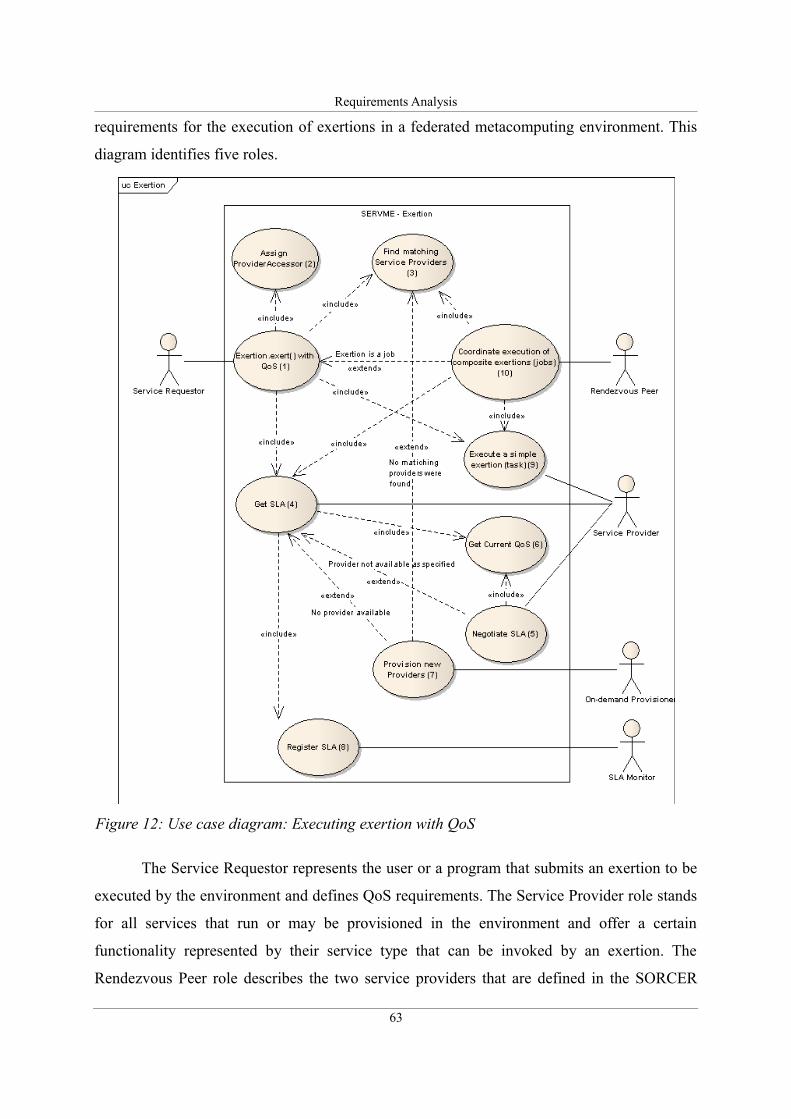
Requirements Analysis
requirements for the execution of exertions in a federated metacomputing environment. This
diagram identifies five roles.
The Service Requestor represents the user or a program that submits an exertion to be
executed by the environment and defines QoS requirements. The Service Provider role stands
for all services that run or may be provisioned in the environment and offer a certain
functionality represented by their service type that can be invoked by an exertion. The
Rendezvous Peer role describes the two service providers that are defined in the SORCER
63
Figure 12: Use case diagram: Executing exertion with QoS
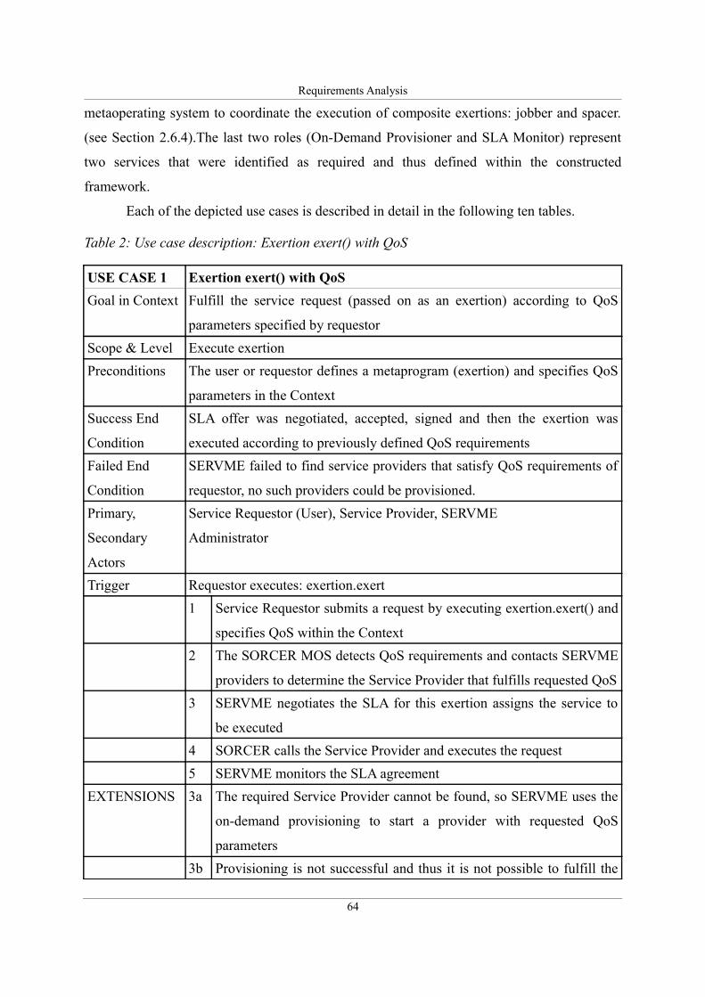
Requirements Analysis
metaoperating system to coordinate the execution of composite exertions: jobber and spacer.
(see Section 2.6.4).The last two roles (On-Demand Provisioner and SLA Monitor) represent
two services that were identified as required and thus defined within the constructed
framework.
Each of the depicted use cases is described in detail in the following ten tables.
Table 2: Use case description: Exertion exert() with QoS
USE CASE 1 Exertion exert() with QoS
Goal in Context Fulfill the service request (passed on as an exertion) according to QoS
parameters specified by requestor
Scope & Level Execute exertion
Preconditions The user or requestor defines a metaprogram (exertion) and specifies QoS
parameters in the Context
Success End
Condition
SLA offer was negotiated, accepted, signed and then the exertion was
executed according to previously defined QoS requirements
Failed End
Condition
SERVME failed to find service providers that satisfy QoS requirements of
requestor, no such providers could be provisioned.
Primary,
Secondary
Actors
Service Requestor (User), Service Provider, SERVME
Administrator
Trigger Requestor executes: exertion.exert
1 Service Requestor submits a request by executing exertion.exert() and
specifies QoS within the Context
2 The SORCER MOS detects QoS requirements and contacts SERVME
providers to determine the Service Provider that fulfills requested QoS
3 SERVME negotiates the SLA for this exertion assigns the service to
be executed
4 SORCER calls the Service Provider and executes the request
5 SERVME monitors the SLA agreement
EXTENSIONS 3a The required Service Provider cannot be found, so SERVME uses the
on-demand provisioning to start a provider with requested QoS
parameters
3b Provisioning is not successful and thus it is not possible to fulfill the
64
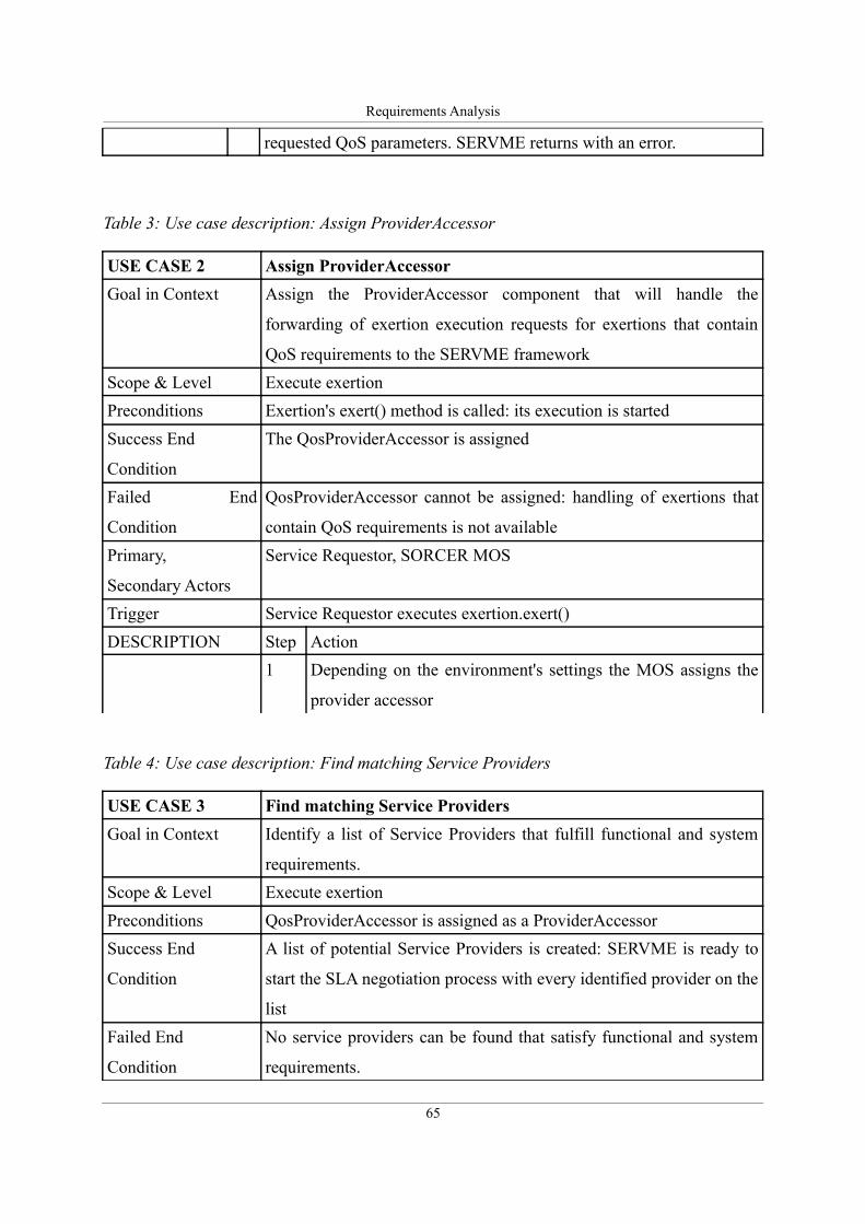
Requirements Analysis
requested QoS parameters. SERVME returns with an error.
Table 3: Use case description: Assign ProviderAccessor
USE CASE 2 Assign ProviderAccessor
Goal in Context Assign the ProviderAccessor component that will handle the
forwarding of exertion execution requests for exertions that contain
QoS requirements to the SERVME framework
Scope & Level Execute exertion
Preconditions Exertion's exert() method is called: its execution is started
Success End
Condition
The QosProviderAccessor is assigned
Failed End
Condition
QosProviderAccessor cannot be assigned: handling of exertions that
contain QoS requirements is not available
Primary,
Secondary Actors
Service Requestor, SORCER MOS
Trigger Service Requestor executes exertion.exert()
DESCRIPTION Step Action
1 Depending on the environment's settings the MOS assigns the
provider accessor
Table 4: Use case description: Find matching Service Providers
USE CASE 3 Find matching Service Providers
Goal in Context Identify a list of Service Providers that fulfill functional and system
requirements.
Scope & Level Execute exertion
Preconditions QosProviderAccessor is assigned as a ProviderAccessor
Success End
Condition
A list of potential Service Providers is created: SERVME is ready to
start the SLA negotiation process with every identified provider on the
list
Failed End
Condition
No service providers can be found that satisfy functional and system
requirements.
65
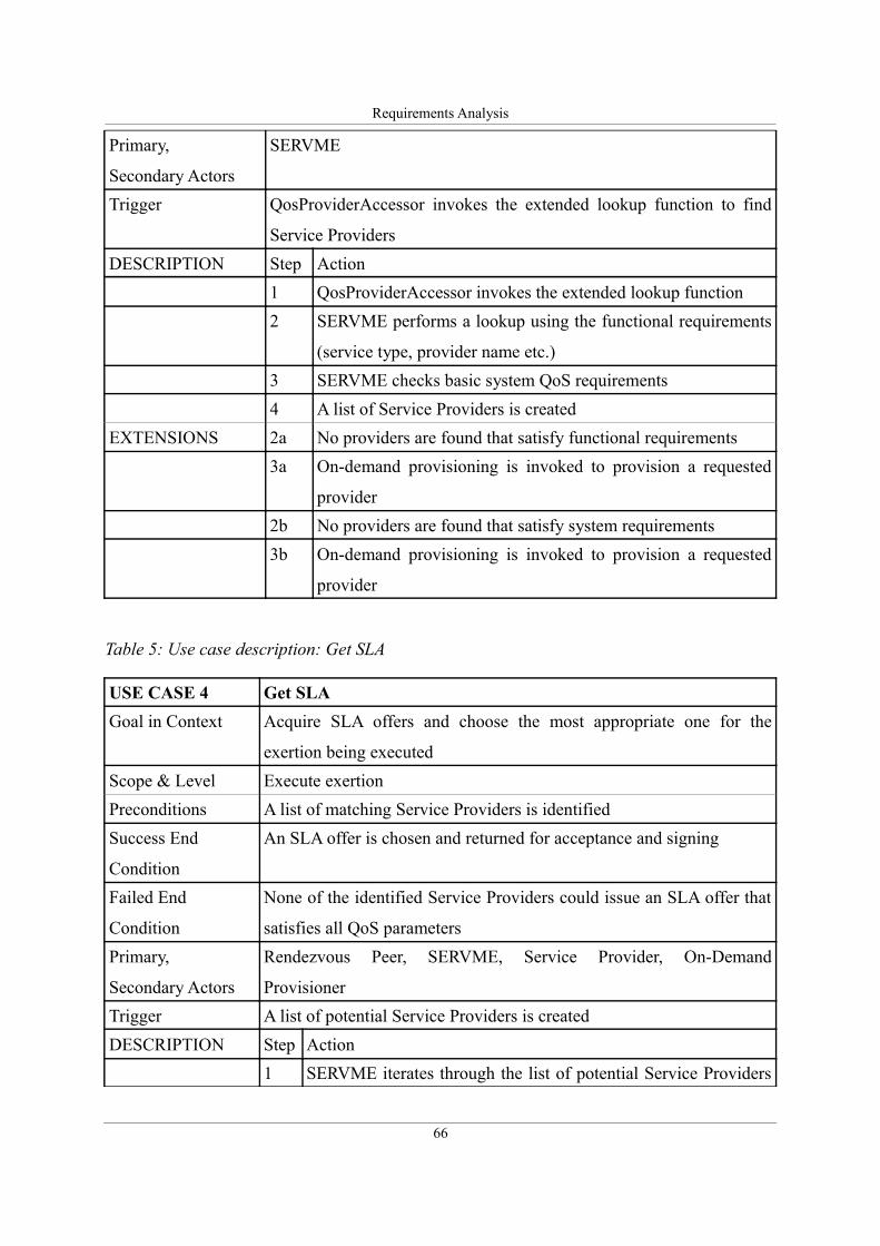
Requirements Analysis
Primary,
Secondary Actors
SERVME
Trigger QosProviderAccessor invokes the extended lookup function to find
Service Providers
DESCRIPTION Step Action
1 QosProviderAccessor invokes the extended lookup function
2 SERVME performs a lookup using the functional requirements
(service type, provider name etc.)
3 SERVME checks basic system QoS requirements
4 A list of Service Providers is created
EXTENSIONS 2a No providers are found that satisfy functional requirements
3a On-demand provisioning is invoked to provision a requested
provider
2b No providers are found that satisfy system requirements
3b On-demand provisioning is invoked to provision a requested
provider
Table 5: Use case description: Get SLA
USE CASE 4 Get SLA
Goal in Context Acquire SLA offers and choose the most appropriate one for the
exertion being executed
Scope & Level Execute exertion
Preconditions A list of matching Service Providers is identified
Success End
Condition
An SLA offer is chosen and returned for acceptance and signing
Failed End
Condition
None of the identified Service Providers could issue an SLA offer that
satisfies all QoS parameters
Primary,
Secondary Actors
Rendezvous Peer, SERVME, Service Provider, On-Demand
Provisioner
Trigger A list of potential Service Providers is created
DESCRIPTION Step Action
1 SERVME iterates through the list of potential Service Providers
66
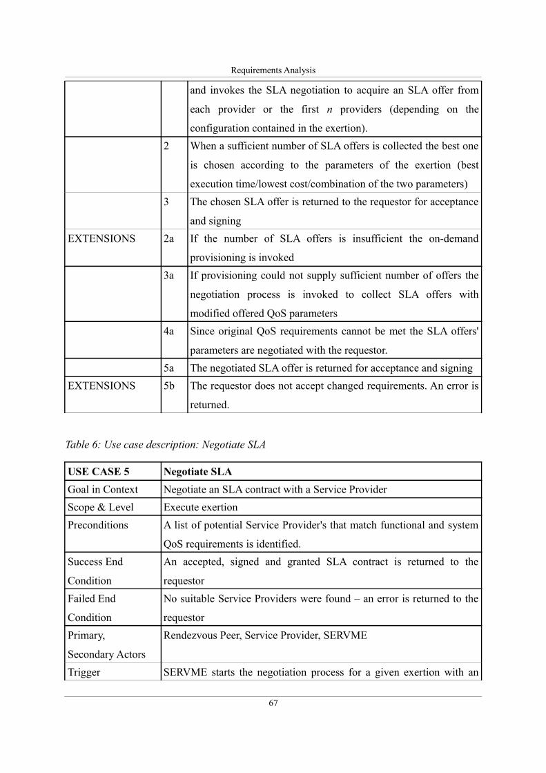
Requirements Analysis
and invokes the SLA negotiation to acquire an SLA offer from
each provider or the first n providers (depending on the
configuration contained in the exertion).
2 When a sufficient number of SLA offers is collected the best one
is chosen according to the parameters of the exertion (best
execution time/lowest cost/combination of the two parameters)
3 The chosen SLA offer is returned to the requestor for acceptance
and signing
EXTENSIONS 2a If the number of SLA offers is insufficient the on-demand
provisioning is invoked
3a If provisioning could not supply sufficient number of offers the
negotiation process is invoked to collect SLA offers with
modified offered QoS parameters
4a Since original QoS requirements cannot be met the SLA offers'
parameters are negotiated with the requestor.
5a The negotiated SLA offer is returned for acceptance and signing
EXTENSIONS 5b The requestor does not accept changed requirements. An error is
returned.
Table 6: Use case description: Negotiate SLA
USE CASE 5 Negotiate SLA
Goal in Context Negotiate an SLA contract with a Service Provider
Scope & Level Execute exertion
Preconditions A list of potential Service Provider's that match functional and system
QoS requirements is identified.
Success End
Condition
An accepted, signed and granted SLA contract is returned to the
requestor
Failed End
Condition
No suitable Service Providers were found – an error is returned to the
requestor
Primary,
Secondary Actors
Rendezvous Peer, Service Provider, SERVME
Trigger SERVME starts the negotiation process for a given exertion with an
67
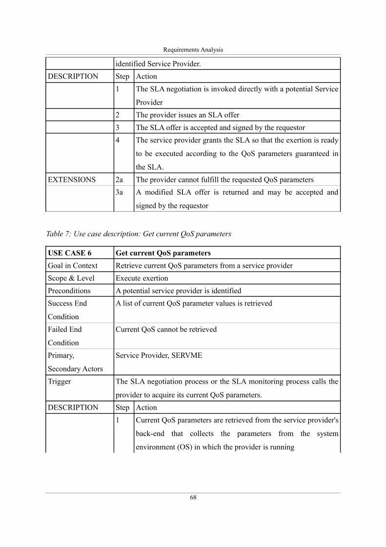
Requirements Analysis
identified Service Provider.
DESCRIPTION Step Action
1 The SLA negotiation is invoked directly with a potential Service
Provider
2 The provider issues an SLA offer
3 The SLA offer is accepted and signed by the requestor
4 The service provider grants the SLA so that the exertion is ready
to be executed according to the QoS parameters guaranteed in
the SLA.
EXTENSIONS 2a The provider cannot fulfill the requested QoS parameters
3a A modified SLA offer is returned and may be accepted and
signed by the requestor
Table 7: Use case description: Get current QoS parameters
USE CASE 6 Get current QoS parameters
Goal in Context Retrieve current QoS parameters from a service provider
Scope & Level Execute exertion
Preconditions A potential service provider is identified
Success End
Condition
A list of current QoS parameter values is retrieved
Failed End
Condition
Current QoS cannot be retrieved
Primary,
Secondary Actors
Service Provider, SERVME
Trigger The SLA negotiation process or the SLA monitoring process calls the
provider to acquire its current QoS parameters.
DESCRIPTION Step Action
1 Current QoS parameters are retrieved from the service provider's
back-end that collects the parameters from the system
environment (OS) in which the provider is running
68
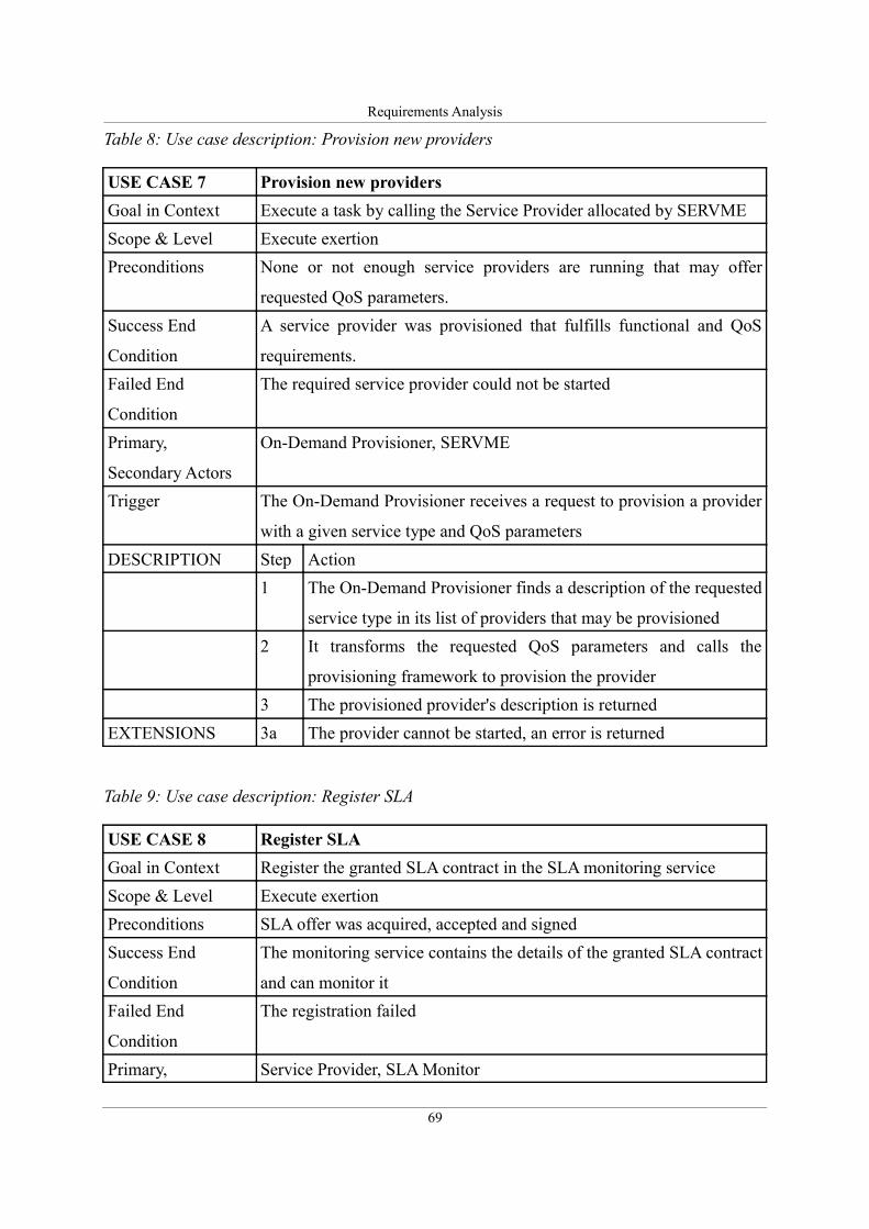
Requirements Analysis
Table 8: Use case description: Provision new providers
USE CASE 7 Provision new providers
Goal in Context Execute a task by calling the Service Provider allocated by SERVME
Scope & Level Execute exertion
Preconditions None or not enough service providers are running that may offer
requested QoS parameters.
Success End
Condition
A service provider was provisioned that fulfills functional and QoS
requirements.
Failed End
Condition
The required service provider could not be started
Primary,
Secondary Actors
On-Demand Provisioner, SERVME
Trigger The On-Demand Provisioner receives a request to provision a provider
with a given service type and QoS parameters
DESCRIPTION Step Action
1 The On-Demand Provisioner finds a description of the requested
service type in its list of providers that may be provisioned
2 It transforms the requested QoS parameters and calls the
provisioning framework to provision the provider
3 The provisioned provider's description is returned
EXTENSIONS 3a The provider cannot be started, an error is returned
Table 9: Use case description: Register SLA
USE CASE 8 Register SLA
Goal in Context Register the granted SLA contract in the SLA monitoring service
Scope & Level Execute exertion
Preconditions SLA offer was acquired, accepted and signed
Success End
Condition
The monitoring service contains the details of the granted SLA contract
and can monitor it
Failed End
Condition
The registration failed
Primary, Service Provider, SLA Monitor
69
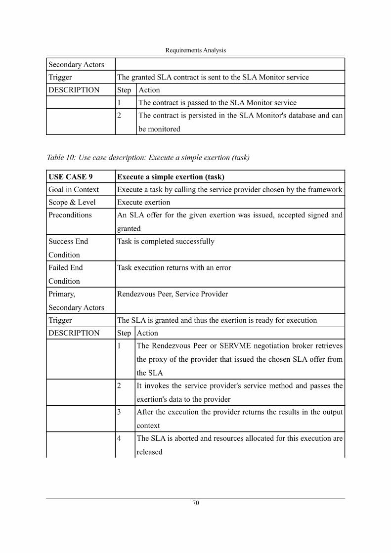
Requirements Analysis
Secondary Actors
Trigger The granted SLA contract is sent to the SLA Monitor service
DESCRIPTION Step Action
1 The contract is passed to the SLA Monitor service
2 The contract is persisted in the SLA Monitor's database and can
be monitored
Table 10: Use case description: Execute a simple exertion (task)
USE CASE 9 Execute a simple exertion (task)
Goal in Context Execute a task by calling the service provider chosen by the framework
Scope & Level Execute exertion
Preconditions An SLA offer for the given exertion was issued, accepted signed and
granted
Success End
Condition
Task is completed successfully
Failed End
Condition
Task execution returns with an error
Primary,
Secondary Actors
Rendezvous Peer, Service Provider
Trigger The SLA is granted and thus the exertion is ready for execution
DESCRIPTION Step Action
1 The Rendezvous Peer or SERVME negotiation broker retrieves
the proxy of the provider that issued the chosen SLA offer from
the SLA
2 It invokes the service provider's service method and passes the
exertion's data to the provider
3 After the execution the provider returns the results in the output
context
4 The SLA is aborted and resources allocated for this execution are
released
70
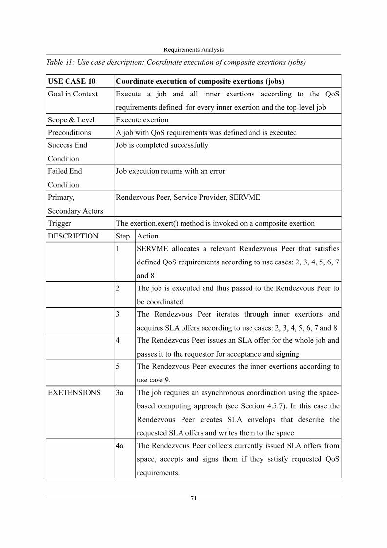
Requirements Analysis
Table 11: Use case description: Coordinate execution of composite exertions (jobs)
USE CASE 10 Coordinate execution of composite exertions (jobs)
Goal in Context Execute a job and all inner exertions according to the QoS
requirements defined for every inner exertion and the top-level job
Scope & Level Execute exertion
Preconditions A job with QoS requirements was defined and is executed
Success End
Condition
Job is completed successfully
Failed End
Condition
Job execution returns with an error
Primary,
Secondary Actors
Rendezvous Peer, Service Provider, SERVME
Trigger The exertion.exert() method is invoked on a composite exertion
DESCRIPTION Step Action
1 SERVME allocates a relevant Rendezvous Peer that satisfies
defined QoS requirements according to use cases: 2, 3, 4, 5, 6, 7
and 8
2 The job is executed and thus passed to the Rendezvous Peer to
be coordinated
3 The Rendezvous Peer iterates through inner exertions and
acquires SLA offers according to use cases: 2, 3, 4, 5, 6, 7 and 8
4 The Rendezvous Peer issues an SLA offer for the whole job and
passes it to the requestor for acceptance and signing
5 The Rendezvous Peer executes the inner exertions according to
use case 9.
EXETENSIONS 3a The job requires an asynchronous coordination using the space-
based computing approach (see Section 4.5.7). In this case the
Rendezvous Peer creates SLA envelops that describe the
requested SLA offers and writes them to the space
4a The Rendezvous Peer collects currently issued SLA offers from
space, accepts and signs them if they satisfy requested QoS
requirements.
71
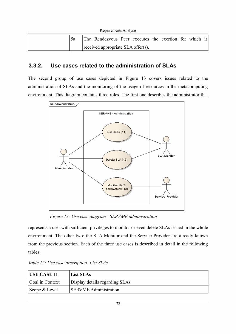
Requirements Analysis
5a The Rendezvous Peer executes the exertion for which it
received appropriate SLA offer(s).
3.3.2. Use cases related to the administration of SLAs
The second group of use cases depicted in Figure 13 covers issues related to the
administration of SLAs and the monitoring of the usage of resources in the metacomputing
environment. This diagram contains three roles. The first one describes the administrator that
represents a user with sufficient privileges to monitor or even delete SLAs issued in the whole
environment. The other two: the SLA Monitor and the Service Provider are already known
from the previous section. Each of the three use cases is described in detail in the following
tables.
Table 12: Use case description: List SLAs
USE CASE 11 List SLAs
Goal in Context Display details regarding SLAs
Scope & Level SERVME Administration
72
Figure 13: Use case diagram - SERVME administration
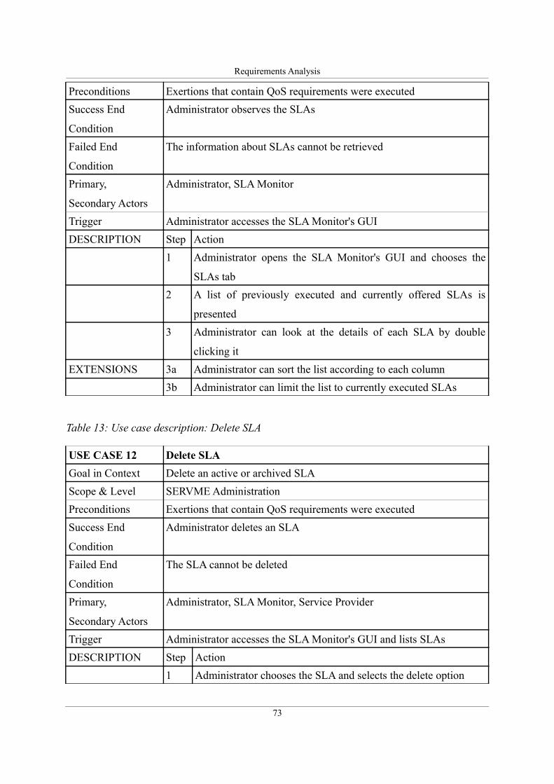
Requirements Analysis
Preconditions Exertions that contain QoS requirements were executed
Success End
Condition
Administrator observes the SLAs
Failed End
Condition
The information about SLAs cannot be retrieved
Primary,
Secondary Actors
Administrator, SLA Monitor
Trigger Administrator accesses the SLA Monitor's GUI
DESCRIPTION Step Action
1 Administrator opens the SLA Monitor's GUI and chooses the
SLAs tab
2 A list of previously executed and currently offered SLAs is
presented
3 Administrator can look at the details of each SLA by double
clicking it
EXTENSIONS 3a Administrator can sort the list according to each column
3b Administrator can limit the list to currently executed SLAs
Table 13: Use case description: Delete SLA
USE CASE 12 Delete SLA
Goal in Context Delete an active or archived SLA
Scope & Level SERVME Administration
Preconditions Exertions that contain QoS requirements were executed
Success End
Condition
Administrator deletes an SLA
Failed End
Condition
The SLA cannot be deleted
Primary,
Secondary Actors
Administrator, SLA Monitor, Service Provider
Trigger Administrator accesses the SLA Monitor's GUI and lists SLAs
DESCRIPTION Step Action
1 Administrator chooses the SLA and selects the delete option
73
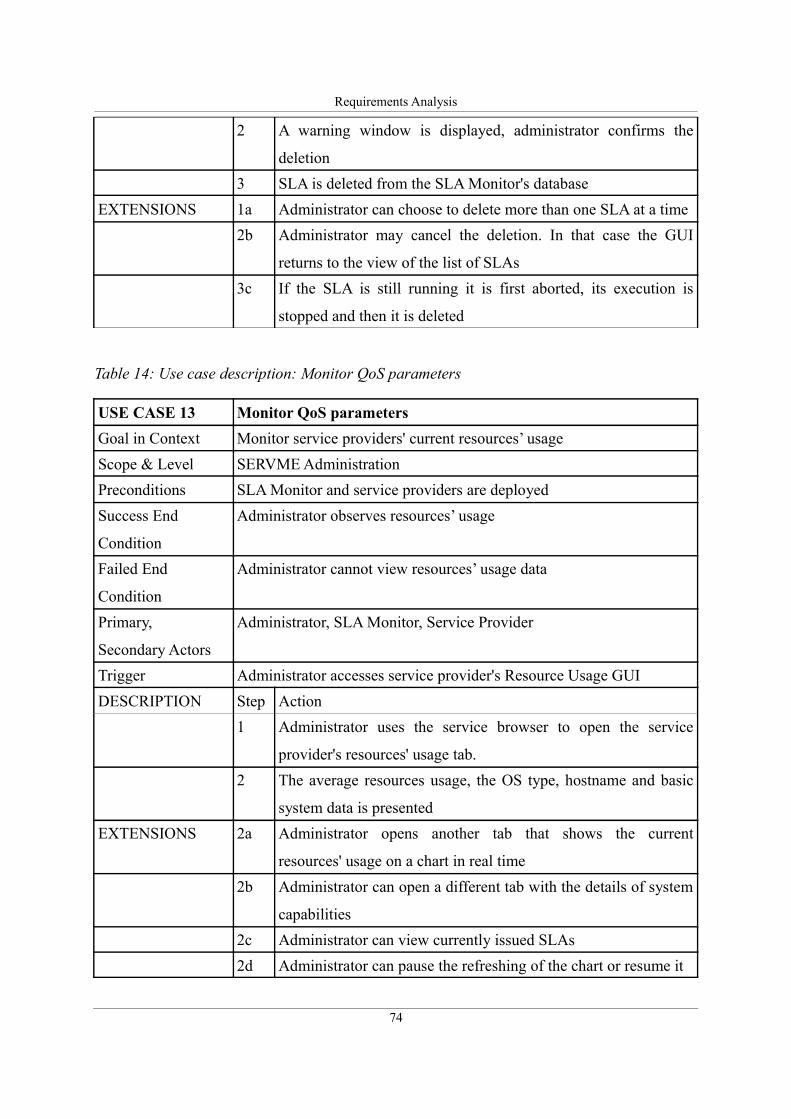
Requirements Analysis
2 A warning window is displayed, administrator confirms the
deletion
3 SLA is deleted from the SLA Monitor's database
EXTENSIONS 1a Administrator can choose to delete more than one SLA at a time
2b Administrator may cancel the deletion. In that case the GUI
returns to the view of the list of SLAs
3c If the SLA is still running it is first aborted, its execution is
stopped and then it is deleted
Table 14: Use case description: Monitor QoS parameters
USE CASE 13 Monitor QoS parameters
Goal in Context Monitor service providers' current resources’ usage
Scope & Level SERVME Administration
Preconditions SLA Monitor and service providers are deployed
Success End
Condition
Administrator observes resources’ usage
Failed End
Condition
Administrator cannot view resources’ usage data
Primary,
Secondary Actors
Administrator, SLA Monitor, Service Provider
Trigger Administrator accesses service provider's Resource Usage GUI
DESCRIPTION Step Action
1 Administrator uses the service browser to open the service
provider's resources' usage tab.
2 The average resources usage, the OS type, hostname and basic
system data is presented
EXTENSIONS 2a Administrator opens another tab that shows the current
resources' usage on a chart in real time
2b Administrator can open a different tab with the details of system
capabilities
2c Administrator can view currently issued SLAs
2d Administrator can pause the refreshing of the chart or resume it
74
Requirements Analysis
3.4. Use case scenario from the real world
To motivate the need to design a resource management module of a metaoperating system and
illustrate the requirements for such a solution on a more concrete example, this section
presents a scenario. It was taken from the real world, where large calculations have to be run
in a distributed environment. The resource management framework being constructed is
meant to become an integral part of the MOS that allows many users to concurrently execute
metaprograms and, consequently it should be capable of allocating resources in a fair way and
at the same time according to users' QoS requirements. This rather complex task can be
exemplified using the following scenario.
A user wants to perform a number of calculations. For example, the goal is to process
magnetic resonance imaging (MRI) of a large number of patients. Many applications used in
bioengineering or neuroscience evolved over time from a number of small scripts and are
therefore inefficient, for example, they cannot take the advantage of modern multi-core/multi-
processor units to speed up the calculations. The processing of MRIs involves a number of
steps that have to be performed for every image. The metacomputing environment extended
by adding a resource management module can be utilized to handle these calculations and use
the available resources in an efficient way.
The resource management solution should contain certain features to optimally
allocate resources for the requested tasks. For example, it should be possible to run the
calculations using different hardware depending on the current goal: the fastest available
machines when costs are insignificant or least expensive ones when time is less important
than the overall cost. The service providers should adjust the number of concurrently run
calculations to the number of available CPUs/cores. It should be possible to exactly tell how
long the execution used the resources and thus what the cost of their use was. Finally, the
proposed solution should be universal and, consequently platform independent.
To illustrate these requirements a heterogeneous testbed containing several different
hardware and software elements is presented in the deployment diagram in Figure 14. This
diagram shows how the proposed framework could be potentially installed and used to run
calculations that solve problems encountered in various domains of science. In this example
the QosCaller service represents the service provider that invokes the calculations and
processes the MRIs whereas other depicted services either belong to the group of SORCER
75
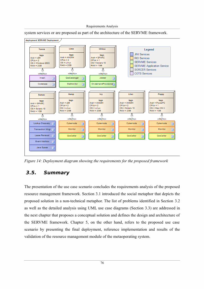
Requirements Analysis
system services or are proposed as part of the architecture of the SERVME framework.
3.5. Summary
The presentation of the use case scenario concludes the requirements analysis of the proposed
resource management framework. Section 3.1 introduced the social metaphor that depicts the
proposed solution in a non-technical metaphor. The list of problems identified in Section 3.2
as well as the detailed analysis using UML use case diagrams (Section 3.3) are addressed in
the next chapter that proposes a conceptual solution and defines the design and architecture of
the SERVME framework. Chapter 5, on the other hand, refers to the proposed use case
scenario by presenting the final deployment, reference implementation and results of the
validation of the resource management module of the metaoperating system.
76
Figure 14: Deployment diagram showing the requirements for the proposed framework
Architecture and Design
Chapter 4. Architecture and Design
Design can be art. Design can be aesthetics. Design is so simple, that's why it is
so complicated.
Paul Rand
The conceptual design of the resource management framework and the resulting architecture
are a result of long discussions and brainstorming sessions. This chapter presents the results of
those discussions that form the basic contribution of this research. The first Section 4.1.
describes the methodology, tools and approach taken during the design phase. Section 4.2.
presents the conceptual design of the resource management framework and identifies the
design topics that had to be addressed. Those topics are described in the following sections:
QoS/SLA Model (Section 4.3), Architecture – Components and Interfaces (Section 4.4).
Finally, Section 4.5 concentrates on interactions within the framework's elements and,
consequently introduces the algorithms and process flows for the SLA negotiation and the
execution of exertions in federated environments.
4.1. Methodology, modeling tools and approaches
Before focusing on the results, it is important to present the methodology and the design
approach chosen to solve the research problem defined at the requirements analysis stage.
This section presents the methodology as well as tools and techniques used during the design
phase, in particular, it describes the Commonality Variability Analysis, Cohesive Design and
UML diagrams.
77
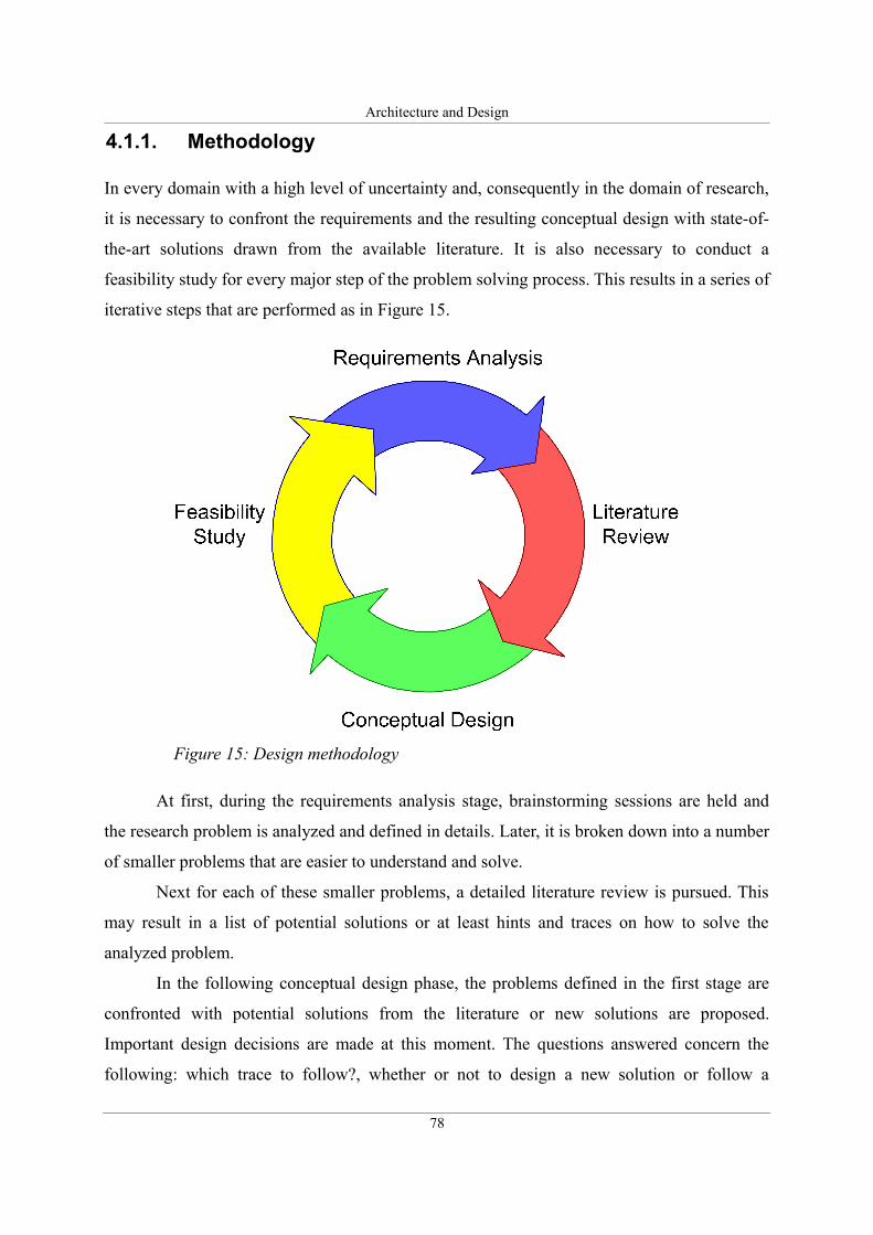
Architecture and Design
4.1.1. Methodology
In every domain with a high level of uncertainty and, consequently in the domain of research,
it is necessary to confront the requirements and the resulting conceptual design with state-of-
the-art solutions drawn from the available literature. It is also necessary to conduct a
feasibility study for every major step of the problem solving process. This results in a series of
iterative steps that are performed as in Figure 15.
At first, during the requirements analysis stage, brainstorming sessions are held and
the research problem is analyzed and defined in details. Later, it is broken down into a number
of smaller problems that are easier to understand and solve.
Next for each of these smaller problems, a detailed literature review is pursued. This
may result in a list of potential solutions or at least hints and traces on how to solve the
analyzed problem.
In the following conceptual design phase, the problems defined in the first stage are
confronted with potential solutions from the literature or new solutions are proposed.
Important design decisions are made at this moment. The questions answered concern the
following: which trace to follow?, whether or not to design a new solution or follow a
78
Figure 15: Design methodology
Architecture and Design
proposal from the literature?, what will be the consequences of these decisions on the
framework being constructed? etc.
Finally, during the Feasibility Study attempts are made to address the most challenging
problems in greater detail. As a result, parts of the conceptual design are turned into technical
design and sometimes even implemented as a prototype to validate the assumptions and the
design decisions made during the previous stage. This step is crucial since as was experienced
during the design of the SERVME framework, many undiscovered problems arise at this
stage. Those new issues often strongly influence the design and may result in the need to
perform the whole iterative design process again.
4.1.2. Commonality variability analysis
During the design of any software or hardware framework, it is crucial to distinguish the parts
that grasp the basic functionality and thus should be permanent from those that require a
certain flexibility to allow the framework to be frequently applied despite the changing
environments. This clear distinction between the common and variable parts should probably
be regarded as the most notable quality of the best designs. The idea is not new. As Coplien et
al. [104] underline this approach was already applied a very long time ago, however, it was
first identified and made public as a common good practice by David Parnas, Edsger Dijkstra,
and Harlan Mills in the 1970s.
Today Commonality Variability or as Coplien et al. [104] describe it: Scope,
Commonality, Variability (SCV) is often applied to contemporary object-oriented frameworks.
Good examples include the Java Authentication and Authorization Service (JAAS) [105] or
the Jini Transaction Management defined in the Jini architecture [63].
In object-oriented design commonality is often expressed by defining fixed
programming interfaces that are extensible and allow different implementations thus leaving
room for variability. Other ways of implementing SCV include various design patterns such as
templates or abstract factoring.
During the design of the SERVME framework, it was a major concern to follow the
SCV approach and, consequently make the framework extensible and universal.
79
Architecture and Design
4.1.3. Cohesive design
Last but not least, an important quality of good software frameworks is the, so called,
cohesive design. The idea is to identify common functionalities and organize them into logical
units or components. A good cohesive design should reduce the number of connections
between components or modules and make the framework easier to understand and apply.
4.1.4. UML diagrams
The Unified Modeling Language (UML) is a standardized general-purpose modeling language
in the field of software engineering [106]. The current UML 2.1 standard contains several
different diagrams and modeling techniques that can be applied at practically all steps of an IT
system's design, implementation and deployment. In the architecture and design phase of the
SERVME framework the following techniques were used:
• Component Diagram – was used to define the basic interfaces and components of the
framework.
• Sequence Diagram – was used to depict the control flow during the execution of a
metaprogram (exertion) by SERVME
• Activity Diagram – was used to model the SLA negotiation process.
The enumeration of UML diagrams concludes the methodology tools and approaches section.
4.2. Conceptual architecture
Despite the vast amount of research that was done in the area of resource management in grid
computing, for example, the conceptual design phase has shown that state-of-the-art solutions
are based on completely different assumptions. As a result, there is very little overlap and
room for reuse. The basic problem lies in the architectural differences. Although spread
geographically and across different organizations, grids tend to be centralized. As Schopf
points out in [107], “in general we can differentiate between a Grid scheduler and a local
resource scheduler, that is, a scheduler that is responsible for scheduling and managing
resources at a single site, or perhaps only for a single cluster or resource.” As a result,
80
Architecture and Design
resource management in grids usually means that jobs10 are sent to resource schedulers that
decide on the node where this job will be executed and add it to the queue for this resource.
Such resource management solutions do not fit to federated metacomputing that is
decentralized by nature and does not know the concept of queuing.
The decentralized nature of this environment is explained by Sobolewski in [1] where
he argues that “...the network exerts the request with the help of the service federation formed
in runtime. In other words, we send the request onto the network implicitly, not to a particular
network object explicitly.” As a consequence of this decentralization, resource management
has to be transparently integrated into the process of exerting an exertion.
In this research, one of the main assumptions is that the network is dynamic and
unpredictable and so is the utilization of various resources. As a result, it is difficult and
makes little sense to schedule and queue jobs. This assumption leads to the main goal of the
resource management framework: to find in runtime service providers that satisfy QoS
requirements or provision them on-demand. Of course, in many cases this goal may be
difficult to achieve and thus some forms of waiting for resources to become free as well as
techniques for load-balancing must be introduced. Those are handled using the space-based
computing approach (see Section 4.5.7) by the spacer coordinating peer. Instead of setting
fixed rules in resource schedulers, this approach promotes the use of free market economy
mechanisms to support a fair allocation of resources to users. However, as experience shows
in some organizations, there is a need for more centralized management and allocation
techniques. This requirement was addressed by introducing execution permissions and
priorities.
Chapter 2, in particular Sections 2.5. and 2.6. , explained the novelty of this approach
to resource management by presenting the three layers of the metacomputing platform. Those
include: the virtual processor (metacomputer) that consists of dynamically bound service
providers, the metaoperating system that contains system services and the metaprogramming
environment that includes metacompute grid applications called exertions (see Figure 16).
The introduction of a resource management framework requires changes at all three levels of
the platform. Although the focus is on the middle layer and, in particular on designing new
system services that will be responsible for handling QoS and managing SLAs, however,
10 Please note that the term job here relates to a job in a grid environment and thus is different from the usual
use of this term in this research where it typically refers to a composite type of exertion.
81
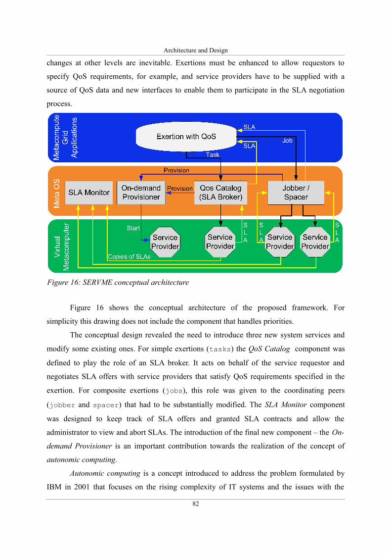
Architecture and Design
changes at other levels are inevitable. Exertions must be enhanced to allow requestors to
specify QoS requirements, for example, and service providers have to be supplied with a
source of QoS data and new interfaces to enable them to participate in the SLA negotiation
process.
Figure 16 shows the conceptual architecture of the proposed framework. For
simplicity this drawing does not include the component that handles priorities.
The conceptual design revealed the need to introduce three new system services and
modify some existing ones. For simple exertions (tasks) the QoS Catalog component was
defined to play the role of an SLA broker. It acts on behalf of the service requestor and
negotiates SLA offers with service providers that satisfy QoS requirements specified in the
exertion. For composite exertions (jobs), this role was given to the coordinating peers
(jobber and spacer) that had to be substantially modified. The SLA Monitor component
was designed to keep track of SLA offers and granted SLA contracts and allow the
administrator to view and abort SLAs. The introduction of the final new component – the On-
demand Provisioner is an important contribution towards the realization of the concept of
autonomic computing.
Autonomic computing is a concept introduced to address the problem formulated by
IBM in 2001 that focuses on the rising complexity of IT systems and the issues with the
82
Figure 16: SERVME conceptual architecture
Architecture and Design
administration and maintenance of complicated environments. IBM researchers propose that
we now try to make computing systems smarter, self-manageable and self-healing [108].
The SERVME framework was designed for a federated, distributed environment
which itself addresses many issues such as network or resource unreliability (see Section
2.6.1. that explains the problem of the 8 Fallacies of Distributed Computing). Another step
towards the realization of the autonomic computing concept is the inclusion of autonomic, on-
demand provisioning that allows services to be started on nodes chosen according to QoS
requirements only when they are actually needed and stop them as soon as they become
obsolete.
The presented conceptual architecture identified a number of specific topics that had to
be addressed to complete the design of the SERVME framework. Those topics include the
design of:
1. QoS/SLA model,
2. components and interfaces – component architecture,
3. SLA negotiation algorithm for simple exertions that contain single tasks,
4. SLA negotiation algorithm for composite exertions,
5. SLA negotiation algorithm for composite exertions executed using the space-based
computing approach,
6. centralized handling of SLA priorities,
7. optimization algorithms for SLA-based QoS resource allocation.
These topics are the subject of the following sections. Every one of them was designed
according to the methodology specified in Section 4.1.1, taking into account the principles of
Commonality, Variability Analysis (Section 4.1.2) and Cohesive Design (Section 4.1.3). UML
diagrams mentioned in section 4.1.4 were used as the basic modeling tool.
4.3. QoS/SLA model
One of the basic steps in creating a resource management framework is the definition of a
common specification language to describe resources as well as QoS requirements.
Section 2.7.1. presented a discussion on different approaches to SLA specification in
the existing literature and explained briefly how the SLA model defined in this research
83
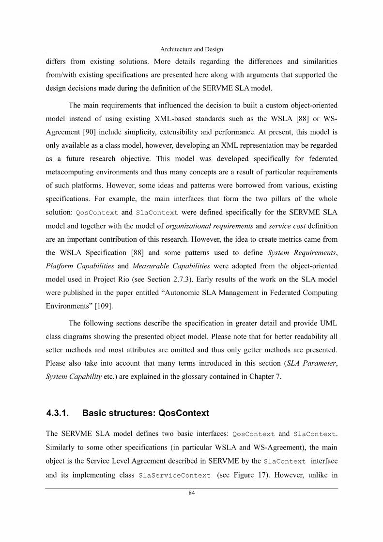
Architecture and Design
differs from existing solutions. More details regarding the differences and similarities
from/with existing specifications are presented here along with arguments that supported the
design decisions made during the definition of the SERVME SLA model.
The main requirements that influenced the decision to built a custom object-oriented
model instead of using existing XML-based standards such as the WSLA [88] or WS-
Agreement [90] include simplicity, extensibility and performance. At present, this model is
only available as a class model, however, developing an XML representation may be regarded
as a future research objective. This model was developed specifically for federated
metacomputing environments and thus many concepts are a result of particular requirements
of such platforms. However, some ideas and patterns were borrowed from various, existing
specifications. For example, the main interfaces that form the two pillars of the whole
solution: QosContext and SlaContext were defined specifically for the SERVME SLA
model and together with the model of organizational requirements and service cost definition
are an important contribution of this research. However, the idea to create metrics came from
the WSLA Specification [88] and some patterns used to define System Requirements,
Platform Capabilities and Measurable Capabilities were adopted from the object-oriented
model used in Project Rio (see Section 2.7.3). Early results of the work on the SLA model
were published in the paper entitled “Autonomic SLA Management in Federated Computing
Environments” [109].
The following sections describe the specification in greater detail and provide UML
class diagrams showing the presented object model. Please note that for better readability all
setter methods and most attributes are omitted and thus only getter methods are presented.
Please also take into account that many terms introduced in this section (SLA Parameter,
System Capability etc.) are explained in the glossary contained in Chapter 7.
4.3.1. Basic structures: QosContext
The SERVME SLA model defines two basic interfaces: QosContext and SlaContext.
Similarly to some other specifications (in particular WSLA and WS-Agreement), the main
object is the Service Level Agreement described in SERVME by the SlaContext interface
and its implementing class SlaServiceContext (see Figure 17). However, unlike in
84
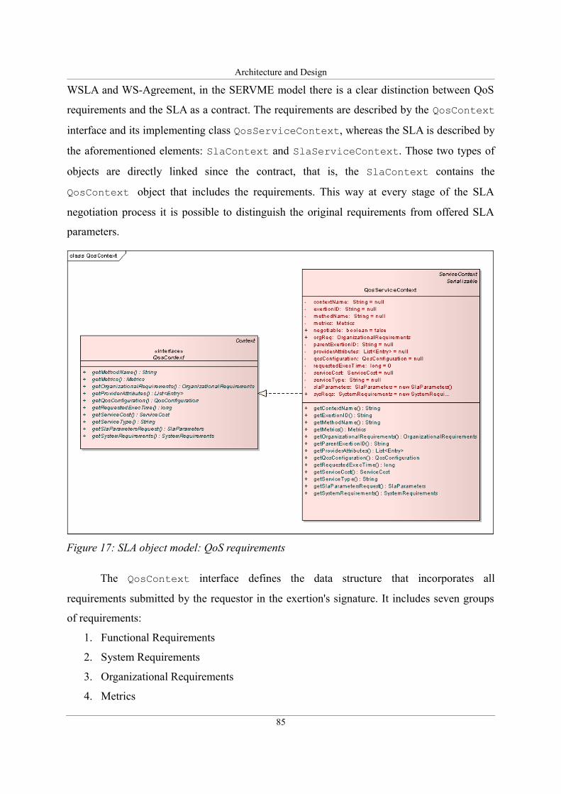
Architecture and Design
WSLA and WS-Agreement, in the SERVME model there is a clear distinction between QoS
requirements and the SLA as a contract. The requirements are described by the QosContext
interface and its implementing class QosServiceContext, whereas the SLA is described by
the aforementioned elements: SlaContext and SlaServiceContext. Those two types of
objects are directly linked since the contract, that is, the SlaContext contains the
QosContext object that includes the requirements. This way at every stage of the SLA
negotiation process it is possible to distinguish the original requirements from offered SLA
parameters.
The QosContext interface defines the data structure that incorporates all
requirements submitted by the requestor in the exertion's signature. It includes seven groups
of requirements:
1. Functional Requirements
2. System Requirements
3. Organizational Requirements
4. Metrics
85
Figure 17: SLA object model: QoS requirements
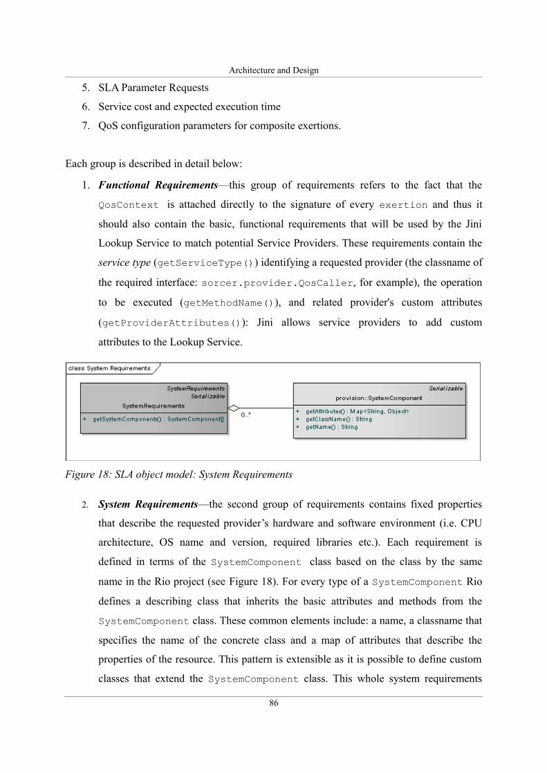
Architecture and Design
5. SLA Parameter Requests
6. Service cost and expected execution time
7. QoS configuration parameters for composite exertions.
Each group is described in detail below:
1. Functional Requirements—this group of requirements refers to the fact that the
QosContext is attached directly to the signature of every exertion and thus it
should also contain the basic, functional requirements that will be used by the Jini
Lookup Service to match potential Service Providers. These requirements contain the
service type (getServiceType()) identifying a requested provider (the classname of
the required interface: sorcer.provider.QosCaller, for example), the operation
to be executed (getMethodName()), and related provider's custom attributes
(getProviderAttributes()): Jini allows service providers to add custom
attributes to the Lookup Service.
2. System Requirements—the second group of requirements contains fixed properties
that describe the requested provider’s hardware and software environment (i.e. CPU
architecture, OS name and version, required libraries etc.). Each requirement is
defined in terms of the SystemComponent class based on the class by the same
name in the Rio project (see Figure 18). For every type of a SystemComponent Rio
defines a describing class that inherits the basic attributes and methods from the
SystemComponent class. These common elements include: a name, a classname that
specifies the name of the concrete class and a map of attributes that describe the
properties of the resource. This pattern is extensible as it is possible to define custom
classes that extend the SystemComponent class. This whole system requirements
86
Figure 18: SLA object model: System Requirements
Architecture and Design
model was borrowed from Rio and thus is completely compatible with the model used
in Rio. To better understand how this pattern is used an example is given below:
A class in Rio that describes the CPU is named:
org.rioproject.system.capability.platform.ProcessorArchitecture
The default name of this resource is set to “Processor” and the default attributes
contain “Available” that defines the number of CPU/Cores on a node and
“Architecture” that defines the system architecture of the node. As a result, to define a
QoS requirement for the exertion to be executed on hosts that contain minimally 4
CPUs and represent the “x86” architecture, we would define the SystemComponent's
properties as:
3. Organizational Requirements—this group of requirements was introduced to allow
exertions to be prioritized. This is a requirement in large deployments where many
users compete for scarce compute resources and therefore there is a need to introduce
centralized priority assignment rules. The SERVME framework defines a special
component called SlaPrioritizer to perform this task and enforce priority and
execution permission depending on organizational parameters. Organizational
Requirements define the properties of the entity that submits the exertion
87
SystemComponent = {
name = "Processor",
classname =
"org.rioproject.system.capability.platform.ProcessorArchitecture"
attributes = { "Available"= 4, "Architecture"= "x86"}
}
Figure 19: SLA object model: Organizational Requirements
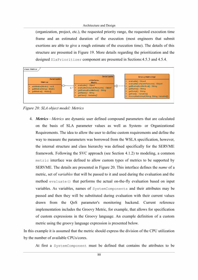
Architecture and Design
(organization, project, etc.), the requested priority range, the requested execution time
frame and an estimated duration of the execution (most engineers that submit
exertions are able to give a rough estimate of the execution time). The details of this
structure are presented in Figure 19. More details regarding the prioritization and the
designed SlaPrioritizer component are presented in Sections:4.5.3 and 4.5.4.
4. Metrics—Metrics are dynamic user defined compound parameters that are calculated
on the basis of SLA parameter values as well as System- or Organizational
Requirements. The idea to allow the user to define custom requirements and define the
way to measure the parameters was borrowed from the WSLA specification, however,
the internal structure and class hierarchy was defined specifically for the SERVME
framework. Following the SVC approach (see Section 4.1.2) to modeling, a common
metric interface was defined to allow custom types of metrics to be supported by
SERVME. The details are presented in Figure 20. This interface defines the name of a
metric, set of variables that will be passed to it and used during the evaluation and the
method evaluate() that performs the actual on-the-fly evaluation based on input
variables. As variables, names of SystemComponents and their attributes may be
passed and then they will be substituted during evaluation with their current values
drawn from the QoS parameter's monitoring backend. Current reference
implementation includes the Groovy Metric, for example, that allows for specification
of custom expressions in the Groovy language. An example definition of a custom
metric using the groovy language expression is presented below.
In this example it is assumed that the metric should express the division of the CPU utilization
by the number of available CPUs/cores.
At first a SystemComponent must be defined that contains the attributes to be
88
Figure 20: SLA object model: Metrics
Architecture and Design
evaluated:
Next a MeasuredResource (see next section) must be defined that refers to the CPU
utilization:
Finally, the metric may be defined as:
5. SLA Parameter Requests—this group of requirements specifies the demanded ranges
of values or demanded fixed values of measurable QoS parameters (CPU utilization,
amount of free memory, free hard drive space etc.) or metrics. The structure is defined
using SlaParameter interface and a default implementation is provided with the
class SlaParameterImpl (see Figure 21). However, custom implementations are
possible as long as they implement the specified interface. The SlaParameter
interface defines an identifier and the requested fixed value
(getRequestedValue()) or a set of threshold values (getLowThreshold(),
89
processor_available =
SystemComponent = {
name = "Processor",
classname =
"org.rioproject.system.capability.platform.ProcessorArchitecture"
attributes = { "Available"= "" }
}
cpu_utilization =
MeasuredResource = {
name = "CPU"
}
script = "result = cpu_utilization /
Double.parseDouble(processor_available)";
exampleMetric = new GroovyMetricImpl(
"ProcAvail_CPU_Util",
script,
{ processor_available, cpu_utilization }
);

Architecture and Design
getHighThreshold()) to define a requested range.
The described interface also contains the SLA Parameter State and the set of its
enumerated, possible values. This parameter is only used when the same data structure
is used to describe offered SLA parameters (in the SlaContext – see below) and
allows us to set the state of the SLA negotiation process for every negotiated
parameter. SlaParameter specifies also the SlaPolicyHandler class that may be
added to define actions (notifications, penalties etc.) invoked during execution when
the contracted parameter values are breached. In other SLA specifications these
parameters often have different names. For example, the WS-Agreement specification
90
Figure 22: SLA object model: Service cost
Figure 21: SLA object model: SLA parameters
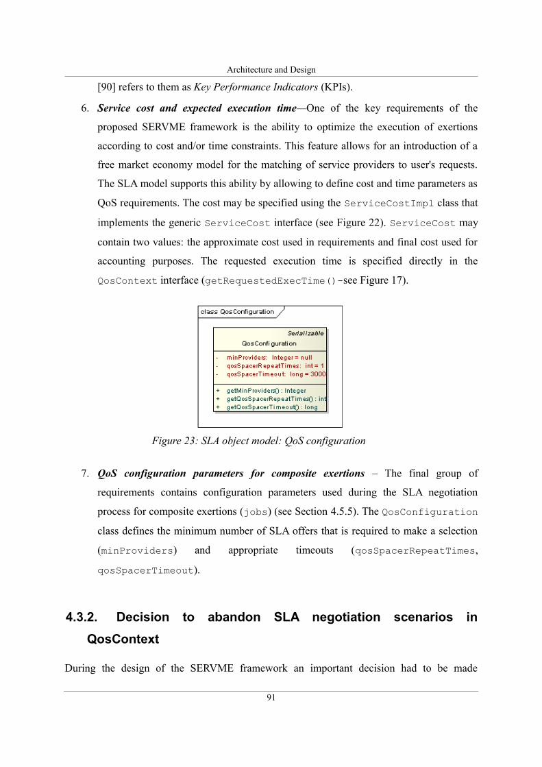
Architecture and Design
[90] refers to them as Key Performance Indicators (KPIs).
6. Service cost and expected execution time—One of the key requirements of the
proposed SERVME framework is the ability to optimize the execution of exertions
according to cost and/or time constraints. This feature allows for an introduction of a
free market economy model for the matching of service providers to user's requests.
The SLA model supports this ability by allowing to define cost and time parameters as
QoS requirements. The cost may be specified using the ServiceCostImpl class that
implements the generic ServiceCost interface (see Figure 22). ServiceCost may
contain two values: the approximate cost used in requirements and final cost used for
accounting purposes. The requested execution time is specified directly in the
QosContext interface (getRequestedExecTime()-see Figure 17).
7. QoS configuration parameters for composite exertions – The final group of
requirements contains configuration parameters used during the SLA negotiation
process for composite exertions (jobs) (see Section 4.5.5). The QosConfiguration
class defines the minimum number of SLA offers that is required to make a selection
(minProviders) and appropriate timeouts (qosSpacerRepeatTimes,
qosSpacerTimeout).
4.3.2. Decision to abandon SLA negotiation scenarios in
QosContext
During the design of the SERVME framework an important decision had to be made
91
Figure 23: SLA object model: QoS configuration
Architecture and Design
regarding the SLA negotiation process and, in particular referred to the way this process is
handled on the requestor side. The question considered was: “whether or not to allow to
specify multiple negotiation scenarios upfront.” Initially the idea was to allow the requestor to
specify a set of rules that would allow it to specify alternative QoS requirements and describe
the alternative acceptable SLA offers to handle various negotiation algorithms and scenarios.
These rules would be used by the broker that negotiates the SLA contract on behalf of the
requestor and would apply in case a service provider that satisfies the requested parameters
could not be found. An important argument for such a solution is the fact that the SORCER
architecture promotes a fire-and-forget approach to executing a task or job by sending the
exertion to the network. The considered solution was to use Groovy scripts embedded in the
QosContext to give the end-user full flexibility. Approaches which involve specifying
alternatives or ranges and trade-offs a priori have been proposed before i.e. by Al-Ali et al. in
[110] and [111]. The introduction of such rules would have influenced the definition of
QosContext in that it would require the rules to be specified in this structure.
However, after long discussions this idea was turned down and a different approach
was followed. Taking into account the popular 80/20 rule, it is doubtful and unnecessary to
assume that such alternative QoS requirements would be often used. Therefore, the decision
was made to allow only one set of QoS requirements and treat the negotiation process
interactively by returning the control to the requestor via an exception if the specified set of
requirements cannot be met. This way the requestor has full control over the negotiation
process and can explicitly implement alternatives on its side instead of using the limited
capabilities of embedded scripts. To conclude, the main arguments for this decision were: high
level of complexity and rare practical applicability.
Such an approach may also be viewed as a too far going simplification and lack of
flexibility therefore at the same time the decision was made to add the possibility of defining
user-defined metrics that can be specified using either simple arithmetic operations or
embedded Groovy scripts giving the requestor full access to all Resource Capabilities as well
as Measurable Capabilities and allowing it to use them as a source of data for custom metrics.
4.3.3. Service Level Agreements contract model: SlaContext
The SERVME SLA model's main object is the SLA contract described by the SlaContext
92
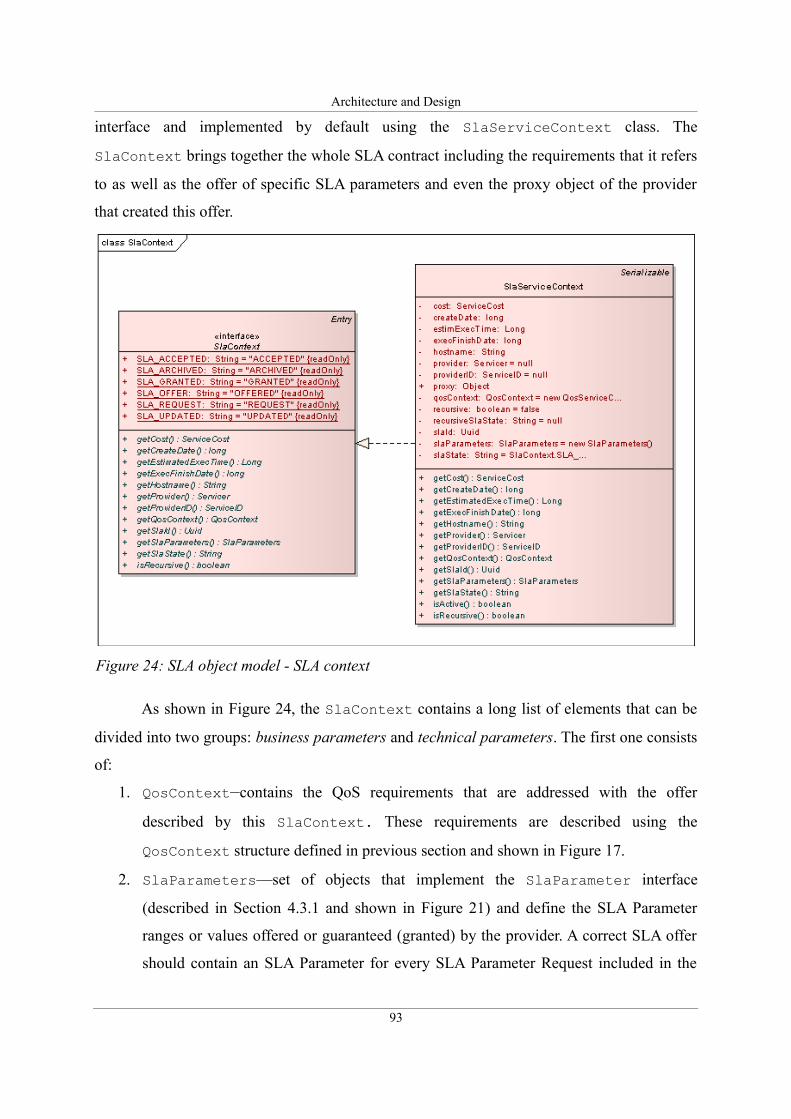
Architecture and Design
interface and implemented by default using the SlaServiceContext class. The
SlaContext brings together the whole SLA contract including the requirements that it refers
to as well as the offer of specific SLA parameters and even the proxy object of the provider
that created this offer.
As shown in Figure 24, the SlaContext contains a long list of elements that can be
divided into two groups: business parameters and technical parameters. The first one consists
of:
1. QosContext—contains the QoS requirements that are addressed with the offer
described by this SlaContext. These requirements are described using the
QosContext structure defined in previous section and shown in Figure 17.
2. SlaParameters—set of objects that implement the SlaParameter interface
(described in Section 4.3.1 and shown in Figure 21) and define the SLA Parameter
ranges or values offered or guaranteed (granted) by the provider. A correct SLA offer
should contain an SLA Parameter for every SLA Parameter Request included in the
93
Figure 24: SLA object model - SLA context
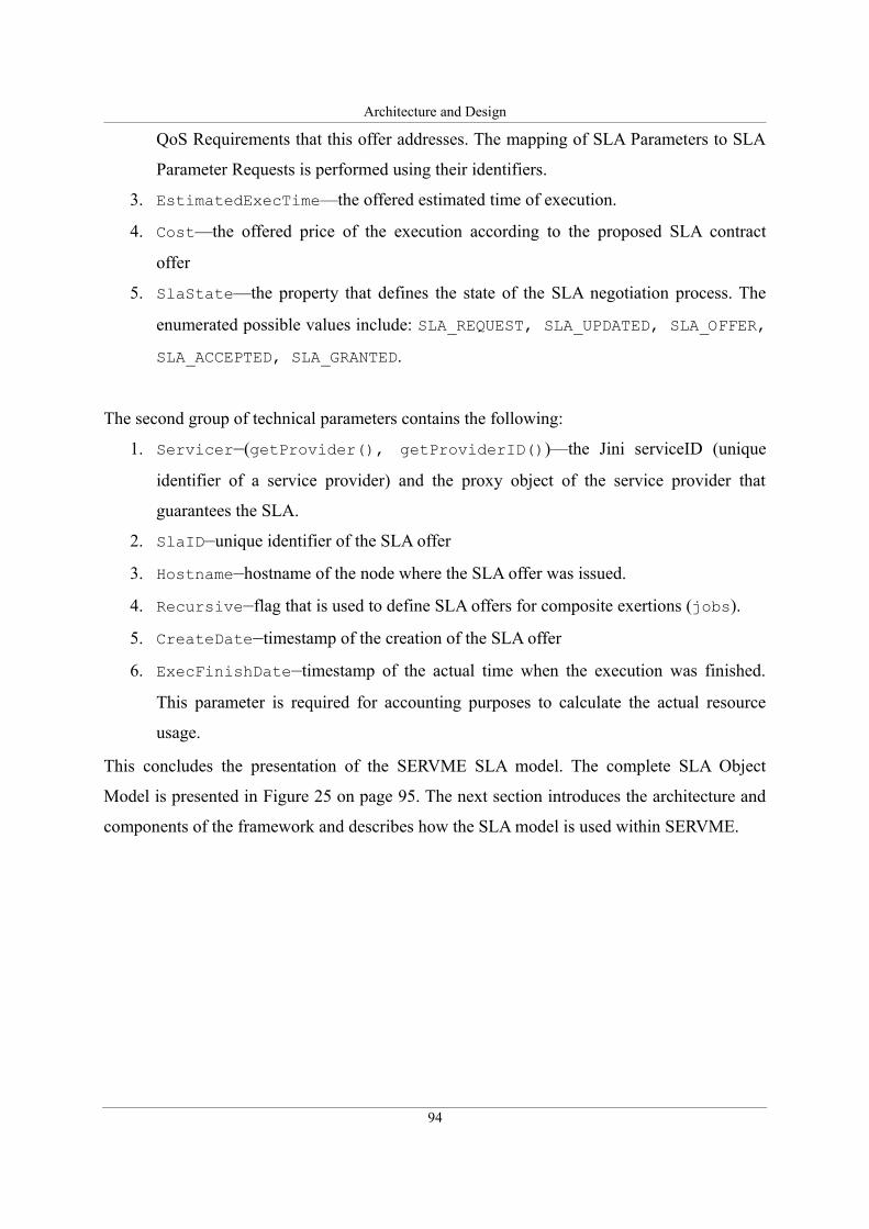
Architecture and Design
QoS Requirements that this offer addresses. The mapping of SLA Parameters to SLA
Parameter Requests is performed using their identifiers.
3. EstimatedExecTime—the offered estimated time of execution.
4. Cost—the offered price of the execution according to the proposed SLA contract
offer
5. SlaState—the property that defines the state of the SLA negotiation process. The
enumerated possible values include: SLA_REQUEST, SLA_UPDATED, SLA_OFFER,
SLA_ACCEPTED, SLA_GRANTED.
The second group of technical parameters contains the following:
1. Servicer—(getProvider(), getProviderID())—the Jini serviceID (unique
identifier of a service provider) and the proxy object of the service provider that
guarantees the SLA.
2. SlaID—unique identifier of the SLA offer
3. Hostname—hostname of the node where the SLA offer was issued.
4. Recursive—flag that is used to define SLA offers for composite exertions (jobs).
5. CreateDate—timestamp of the creation of the SLA offer
6. ExecFinishDate—timestamp of the actual time when the execution was finished.
This parameter is required for accounting purposes to calculate the actual resource
usage.
This concludes the presentation of the SERVME SLA model. The complete SLA Object
Model is presented in Figure 25 on page 95. The next section introduces the architecture and
components of the framework and describes how the SLA model is used within SERVME.
94
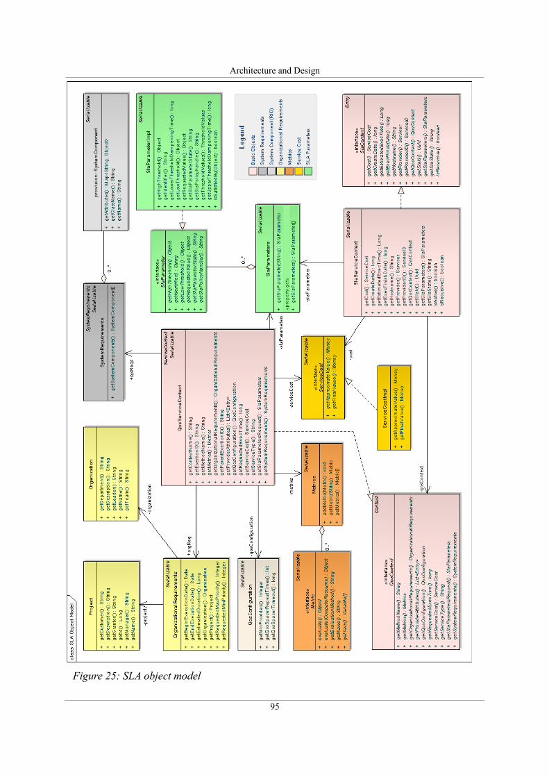
Architecture and Design
95
Figure 25: SLA object model
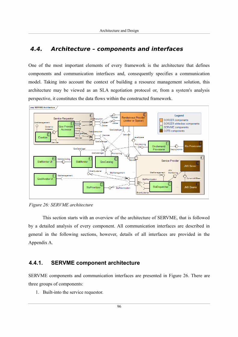
Architecture and Design
4.4. Architecture – components and interfaces
One of the most important elements of every framework is the architecture that defines
components and communication interfaces and, consequently specifies a communication
model. Taking into account the context of building a resource management solution, this
architecture may be viewed as an SLA negotiation protocol or, from a system's analysis
perspective, it constitutes the data flows within the constructed framework.
This section starts with an overview of the architecture of SERVME, that is followed
by a detailed analysis of every component. All communication interfaces are described in
general in the following sections, however, details of all interfaces are provided in the
Appendix A.
4.4.1. SERVME component architecture
SERVME components and communication interfaces are presented in Figure 26. There are
three groups of components:
1. Built-into the service requestor.
96
Figure 26: SERVME architecture
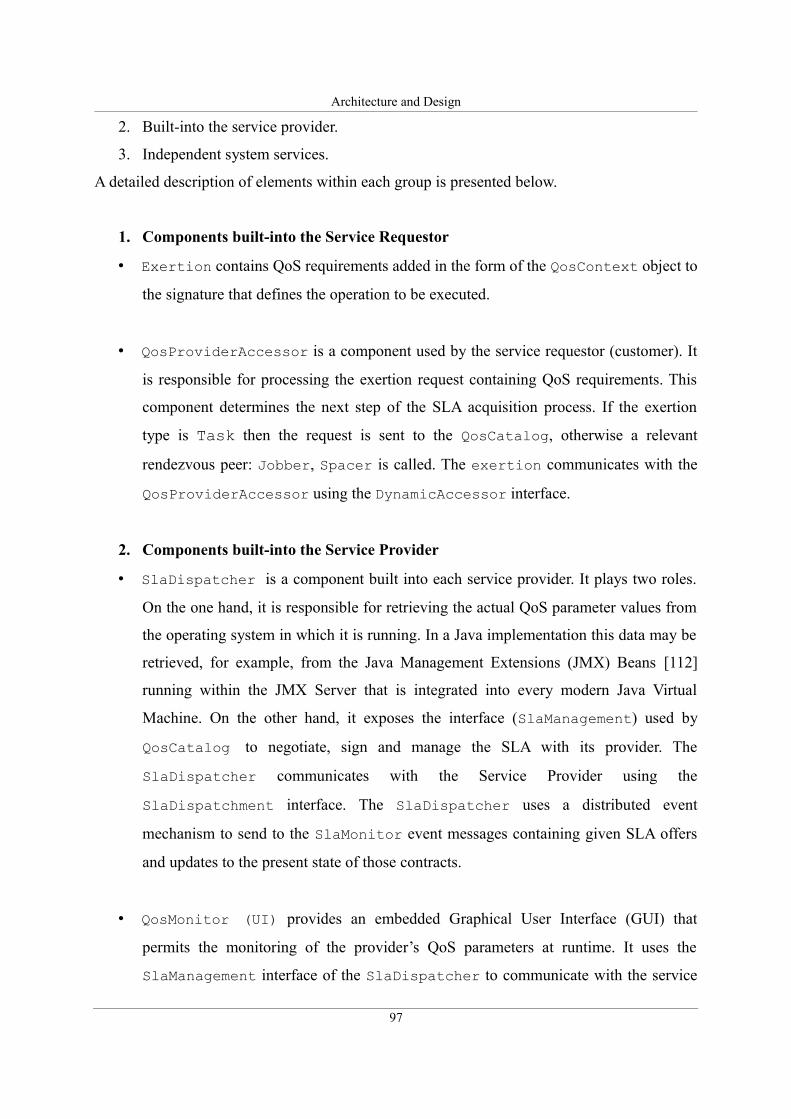
Architecture and Design
2. Built-into the service provider.
3. Independent system services.
A detailed description of elements within each group is presented below.
1. Components built-into the Service Requestor
• Exertion contains QoS requirements added in the form of the QosContext object to
the signature that defines the operation to be executed.
• QosProviderAccessor is a component used by the service requestor (customer). It
is responsible for processing the exertion request containing QoS requirements. This
component determines the next step of the SLA acquisition process. If the exertion
type is Task then the request is sent to the QosCatalog, otherwise a relevant
rendezvous peer: Jobber, Spacer is called. The exertion communicates with the
QosProviderAccessor using the DynamicAccessor interface.
2. Components built-into the Service Provider
• SlaDispatcher is a component built into each service provider. It plays two roles.
On the one hand, it is responsible for retrieving the actual QoS parameter values from
the operating system in which it is running. In a Java implementation this data may be
retrieved, for example, from the Java Management Extensions (JMX) Beans [112]
running within the JMX Server that is integrated into every modern Java Virtual
Machine. On the other hand, it exposes the interface (SlaManagement) used by
QosCatalog to negotiate, sign and manage the SLA with its provider. The
SlaDispatcher communicates with the Service Provider using the
SlaDispatchment interface. The SlaDispatcher uses a distributed event
mechanism to send to the SlaMonitor event messages containing given SLA offers
and updates to the present state of those contracts.
• QosMonitor (UI) provides an embedded Graphical User Interface (GUI) that
permits the monitoring of the provider’s QoS parameters at runtime. It uses the
SlaManagement interface of the SlaDispatcher to communicate with the service
97
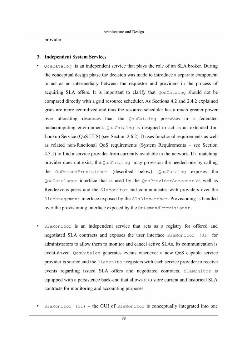
Architecture and Design
provider.
3. Independent System Services
• QosCatalog is an independent service that plays the role of an SLA broker. During
the conceptual design phase the decision was made to introduce a separate component
to act as an intermediary between the requestor and providers in the process of
acquiring SLA offers. It is important to clarify that QosCatalog should not be
compared directly with a grid resource scheduler. As Sections 4.2 and 2.4.2 explained
grids are more centralized and thus the resource scheduler has a much greater power
over allocating resources than the QosCatalog possesses in a federated
metacomputing environment. QosCatalog is designed to act as an extended Jini
Lookup Service (QoS LUS) (see Section 2.6.2). It uses functional requirements as well
as related non-functional QoS requirements (System Requirements – see Section
4.3.1) to find a service provider from currently available in the network. If a matching
provider does not exist, the QosCatalog may provision the needed one by calling
the OnDemandProvisioner (described below). QosCatalog exposes the
QosCataloger interface that is used by the QosProviderAccessor as well as
Rendezvous peers and the SlaMonitor and communicates with providers over the
SlaManagement interface exposed by the SlaDispatcher. Provisioning is handled
over the provisioning interface exposed by the OnDemandProvisioner.
• SlaMonitor is an independent service that acts as a registry for offered and
negotiated SLA contracts and exposes the user interface SlaMonitor (UI) for
administrators to allow them to monitor and cancel active SLAs. Its communication is
event-driven. QosCatalog generates events whenever a new QoS capable service
provider is started and the SlaMonitor registers with each service provider to receive
events regarding issued SLA offers and negotiated contracts. SlaMonitor is
equipped with a persistence back-end that allows it to store current and historical SLA
contracts for monitoring and accounting purposes.
• SlaMonitor (UI) – the GUI of SlaMonitor is conceptually integrated into one
98
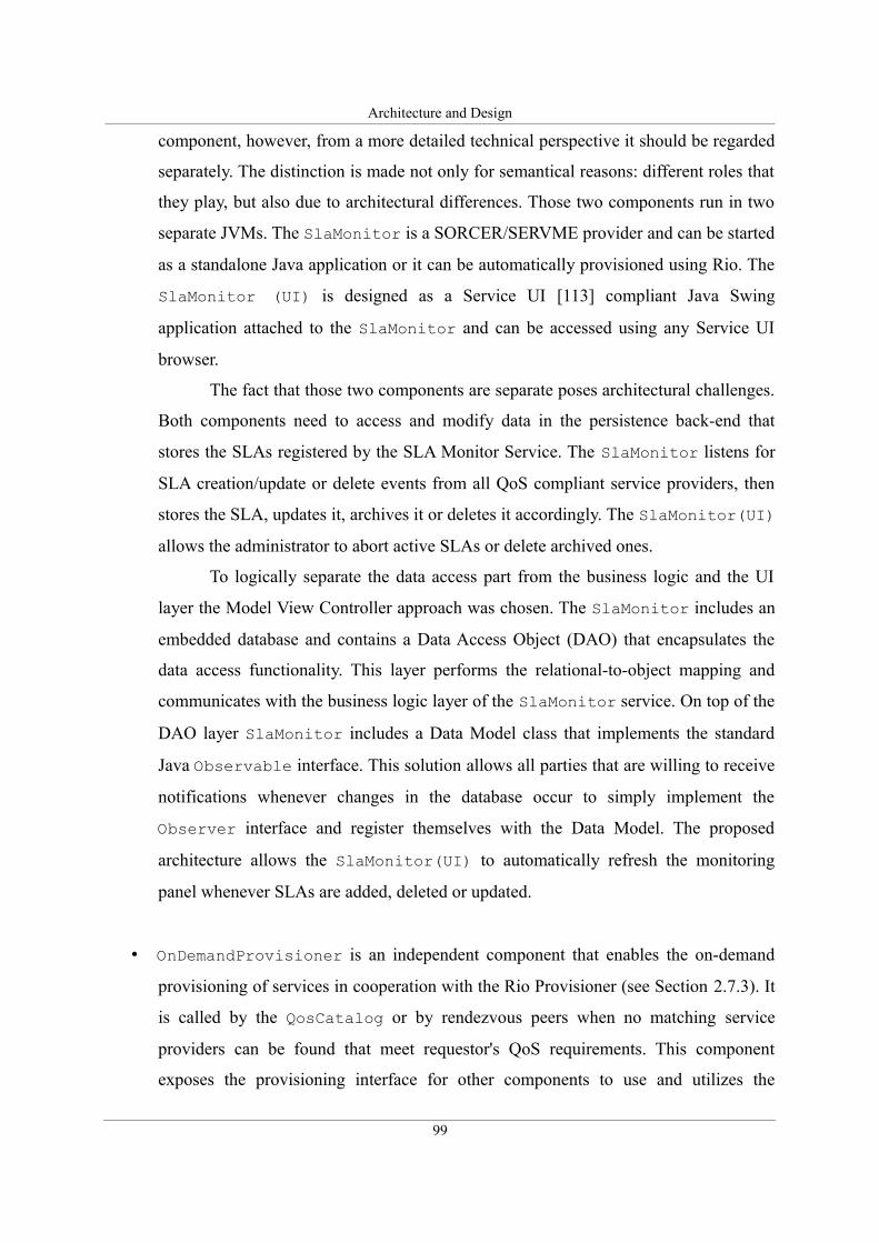
Architecture and Design
component, however, from a more detailed technical perspective it should be regarded
separately. The distinction is made not only for semantical reasons: different roles that
they play, but also due to architectural differences. Those two components run in two
separate JVMs. The SlaMonitor is a SORCER/SERVME provider and can be started
as a standalone Java application or it can be automatically provisioned using Rio. The
SlaMonitor (UI) is designed as a Service UI [113] compliant Java Swing
application attached to the SlaMonitor and can be accessed using any Service UI
browser.
The fact that those two components are separate poses architectural challenges.
Both components need to access and modify data in the persistence back-end that
stores the SLAs registered by the SLA Monitor Service. The SlaMonitor listens for
SLA creation/update or delete events from all QoS compliant service providers, then
stores the SLA, updates it, archives it or deletes it accordingly. The SlaMonitor(UI)
allows the administrator to abort active SLAs or delete archived ones.
To logically separate the data access part from the business logic and the UI
layer the Model View Controller approach was chosen. The SlaMonitor includes an
embedded database and contains a Data Access Object (DAO) that encapsulates the
data access functionality. This layer performs the relational-to-object mapping and
communicates with the business logic layer of the SlaMonitor service. On top of the
DAO layer SlaMonitor includes a Data Model class that implements the standard
Java Observable interface. This solution allows all parties that are willing to receive
notifications whenever changes in the database occur to simply implement the
Observer interface and register themselves with the Data Model. The proposed
architecture allows the SlaMonitor(UI) to automatically refresh the monitoring
panel whenever SLAs are added, deleted or updated.
• OnDemandProvisioner is an independent component that enables the on-demand
provisioning of services in cooperation with the Rio Provisioner (see Section 2.7.3). It
is called by the QosCatalog or by rendezvous peers when no matching service
providers can be found that meet requestor's QoS requirements. This component
exposes the provisioning interface for other components to use and utilizes the
99
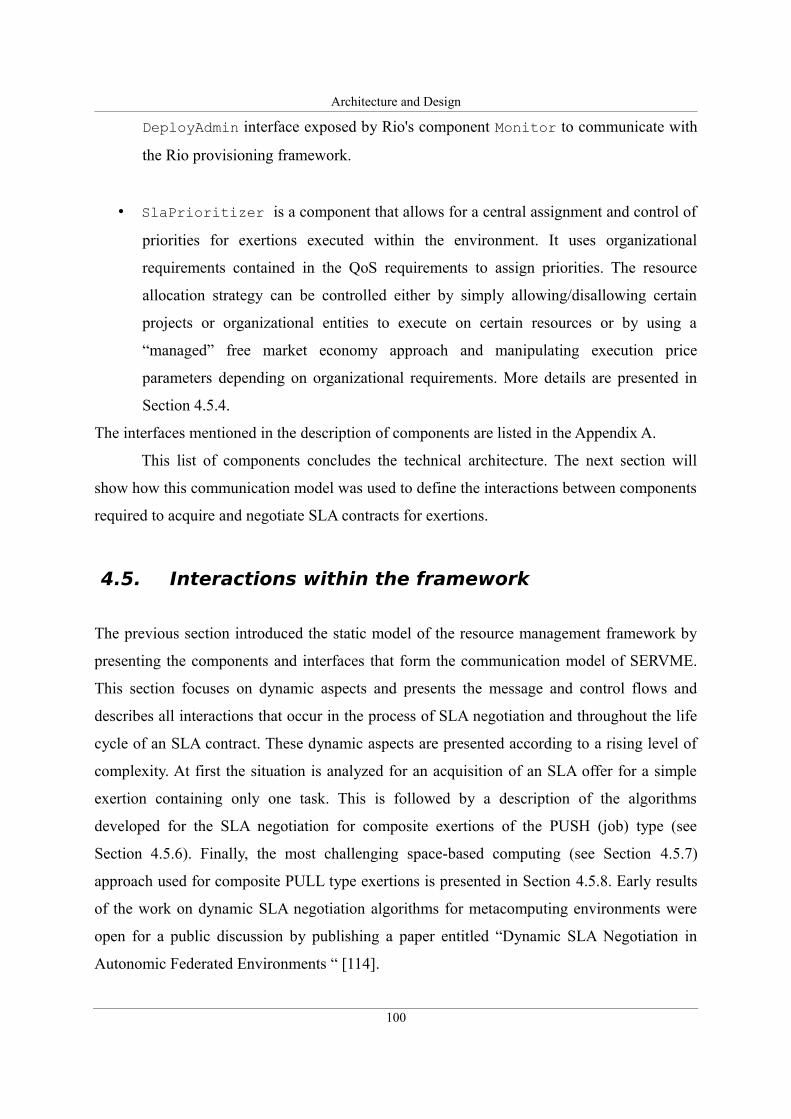
Architecture and Design
DeployAdmin interface exposed by Rio's component Monitor to communicate with
the Rio provisioning framework.
• SlaPrioritizer is a component that allows for a central assignment and control of
priorities for exertions executed within the environment. It uses organizational
requirements contained in the QoS requirements to assign priorities. The resource
allocation strategy can be controlled either by simply allowing/disallowing certain
projects or organizational entities to execute on certain resources or by using a
“managed” free market economy approach and manipulating execution price
parameters depending on organizational requirements. More details are presented in
Section 4.5.4.
The interfaces mentioned in the description of components are listed in the Appendix A.
This list of components concludes the technical architecture. The next section will
show how this communication model was used to define the interactions between components
required to acquire and negotiate SLA contracts for exertions.
4.5. Interactions within the framework
The previous section introduced the static model of the resource management framework by
presenting the components and interfaces that form the communication model of SERVME.
This section focuses on dynamic aspects and presents the message and control flows and
describes all interactions that occur in the process of SLA negotiation and throughout the life
cycle of an SLA contract. These dynamic aspects are presented according to a rising level of
complexity. At first the situation is analyzed for an acquisition of an SLA offer for a simple
exertion containing only one task. This is followed by a description of the algorithms
developed for the SLA negotiation for composite exertions of the PUSH (job) type (see
Section 4.5.6). Finally, the most challenging space-based computing (see Section 4.5.7)
approach used for composite PULL type exertions is presented in Section 4.5.8. Early results
of the work on dynamic SLA negotiation algorithms for metacomputing environments were
open for a public discussion by publishing a paper entitled “Dynamic SLA Negotiation in
Autonomic Federated Environments “ [114].
100
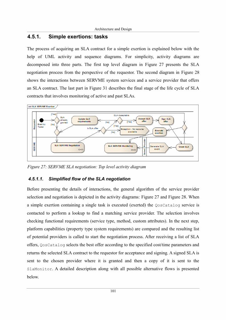
Architecture and Design
4.5.1. Simple exertions: tasks
The process of acquiring an SLA contract for a simple exertion is explained below with the
help of UML activity and sequence diagrams. For simplicity, activity diagrams are
decomposed into three parts. The first top level diagram in Figure 27 presents the SLA
negotiation process from the perspective of the requestor. The second diagram in Figure 28
shows the interactions between SERVME system services and a service provider that offers
an SLA contract. The last part in Figure 31 describes the final stage of the life cycle of SLA
contracts that involves monitoring of active and past SLAs.
4.5.1.1. Simplified flow of the SLA negotiation
Before presenting the details of interactions, the general algorithm of the service provider
selection and negotiation is depicted in the activity diagrams: Figure 27 and Figure 28. When
a simple exertion containing a single task is executed (exerted) the QosCatalog service is
contacted to perform a lookup to find a matching service provider. The selection involves
checking functional requirements (service type, method, custom attributes). In the next step,
platform capabilities (property type system requirements) are compared and the resulting list
of potential providers is called to start the negotiation process. After receiving a list of SLA
offers, QosCatalog selects the best offer according to the specified cost/time parameters and
returns the selected SLA contract to the requestor for acceptance and signing. A signed SLA is
sent to the chosen provider where it is granted and then a copy of it is sent to the
SlaMonitor. A detailed description along with all possible alternative flows is presented
below.
101
Figure 27: SERVME SLA negotiation: Top level activity diagram
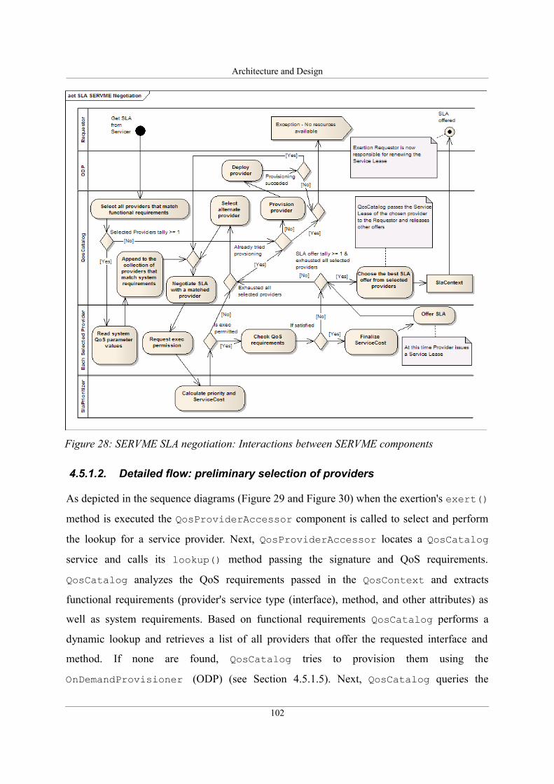
Architecture and Design
4.5.1.2. Detailed flow: preliminary selection of providers
As depicted in the sequence diagrams (Figure 29 and Figure 30) when the exertion's exert()
method is executed the QosProviderAccessor component is called to select and perform
the lookup for a service provider. Next, QosProviderAccessor locates a QosCatalog
service and calls its lookup() method passing the signature and QoS requirements.
QosCatalog analyzes the QoS requirements passed in the QosContext and extracts
functional requirements (provider's service type (interface), method, and other attributes) as
well as system requirements. Based on functional requirements QosCatalog performs a
dynamic lookup and retrieves a list of all providers that offer the requested interface and
method. If none are found, QosCatalog tries to provision them using the
OnDemandProvisioner (ODP) (see Section 4.5.1.5). Next, QosCatalog queries the
102
Figure 28: SERVME SLA negotiation: Interactions between SERVME components
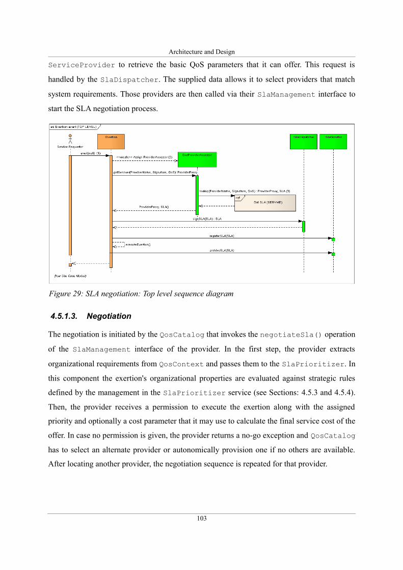
Architecture and Design
ServiceProvider to retrieve the basic QoS parameters that it can offer. This request is
handled by the SlaDispatcher. The supplied data allows it to select providers that match
system requirements. Those providers are then called via their SlaManagement interface to
start the SLA negotiation process.
4.5.1.3. Negotiation
The negotiation is initiated by the QosCatalog that invokes the negotiateSla() operation
of the SlaManagement interface of the provider. In the first step, the provider extracts
organizational requirements from QosContext and passes them to the SlaPrioritizer. In
this component the exertion's organizational properties are evaluated against strategic rules
defined by the management in the SlaPrioritizer service (see Sections: 4.5.3 and 4.5.4).
Then, the provider receives a permission to execute the exertion along with the assigned
priority and optionally a cost parameter that it may use to calculate the final service cost of the
offer. In case no permission is given, the provider returns a no-go exception and QosCatalog
has to select an alternate provider or autonomically provision one if no others are available.
After locating another provider, the negotiation sequence is repeated for that provider.
103
Figure 29: SLA negotiation: Top level sequence diagram
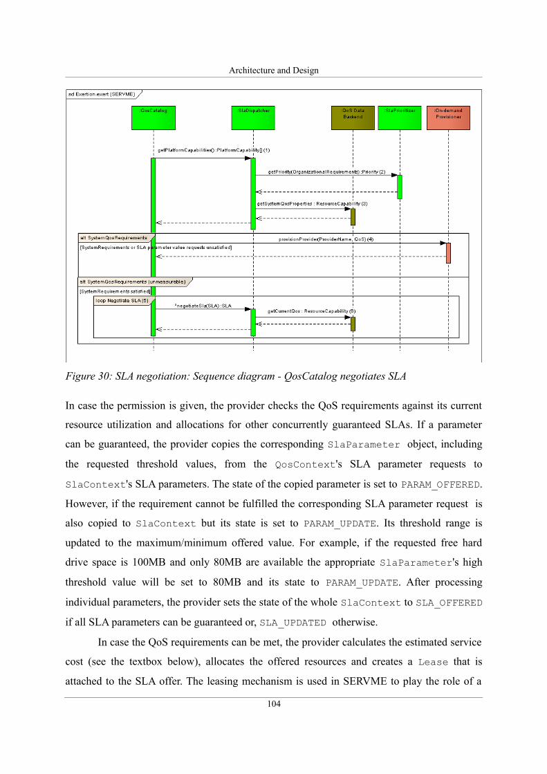
Architecture and Design
In case the permission is given, the provider checks the QoS requirements against its current
resource utilization and allocations for other concurrently guaranteed SLAs. If a parameter
can be guaranteed, the provider copies the corresponding SlaParameter object, including
the requested threshold values, from the QosContext's SLA parameter requests to
SlaContext's SLA parameters. The state of the copied parameter is set to PARAM_OFFERED.
However, if the requirement cannot be fulfilled the corresponding SLA parameter request is
also copied to SlaContext but its state is set to PARAM_UPDATE. Its threshold range is
updated to the maximum/minimum offered value. For example, if the requested free hard
drive space is 100MB and only 80MB are available the appropriate SlaParameter's high
threshold value will be set to 80MB and its state to PARAM_UPDATE. After processing
individual parameters, the provider sets the state of the whole SlaContext to SLA_OFFERED
if all SLA parameters can be guaranteed or, SLA_UPDATED otherwise.
In case the QoS requirements can be met, the provider calculates the estimated service
cost (see the textbox below), allocates the offered resources and creates a Lease that is
attached to the SLA offer. The leasing mechanism is used in SERVME to play the role of a
104
Figure 30: SLA negotiation: Sequence diagram - QosCatalog negotiates SLA
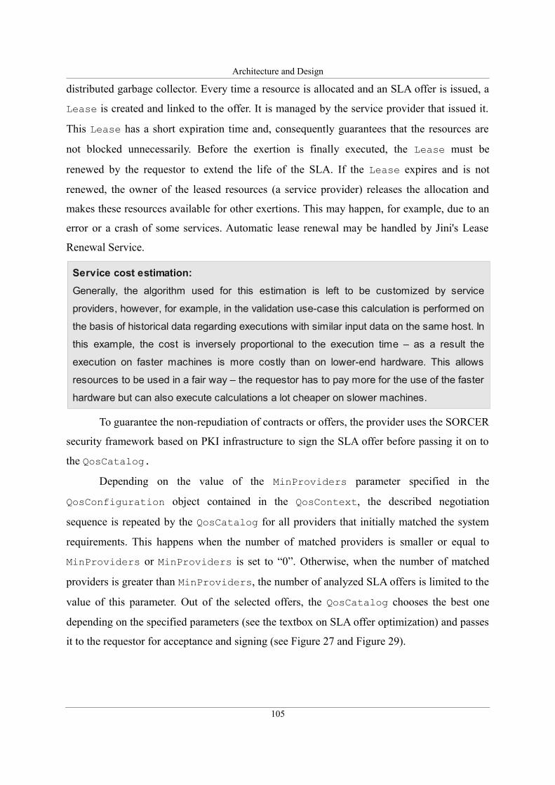
Architecture and Design
distributed garbage collector. Every time a resource is allocated and an SLA offer is issued, a
Lease is created and linked to the offer. It is managed by the service provider that issued it.
This Lease has a short expiration time and, consequently guarantees that the resources are
not blocked unnecessarily. Before the exertion is finally executed, the Lease must be
renewed by the requestor to extend the life of the SLA. If the Lease expires and is not
renewed, the owner of the leased resources (a service provider) releases the allocation and
makes these resources available for other exertions. This may happen, for example, due to an
error or a crash of some services. Automatic lease renewal may be handled by Jini's Lease
Renewal Service.
To guarantee the non-repudiation of contracts or offers, the provider uses the SORCER
security framework based on PKI infrastructure to sign the SLA offer before passing it on to
the QosCatalog.
Depending on the value of the MinProviders parameter specified in the
QosConfiguration object contained in the QosContext, the described negotiation
sequence is repeated by the QosCatalog for all providers that initially matched the system
requirements. This happens when the number of matched providers is smaller or equal to
MinProviders or MinProviders is set to “0”. Otherwise, when the number of matched
providers is greater than MinProviders, the number of analyzed SLA offers is limited to the
value of this parameter. Out of the selected offers, the QosCatalog chooses the best one
depending on the specified parameters (see the textbox on SLA offer optimization) and passes
it to the requestor for acceptance and signing (see Figure 27 and Figure 29).
105
Service cost estimation:
Generally, the algorithm used for this estimation is left to be customized by service
providers, however, for example, in the validation use-case this calculation is performed on
the basis of historical data regarding executions with similar input data on the same host. In
this example, the cost is inversely proportional to the execution time – as a result the
execution on faster machines is more costly than on lower-end hardware. This allows
resources to be used in a fair way – the requestor has to pay more for the use of the faster
hardware but can also execute calculations a lot cheaper on slower machines.
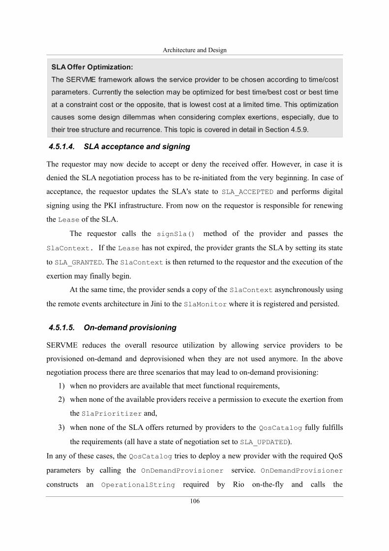
Architecture and Design
4.5.1.4. SLA acceptance and signing
The requestor may now decide to accept or deny the received offer. However, in case it is
denied the SLA negotiation process has to be re-initiated from the very beginning. In case of
acceptance, the requestor updates the SLA's state to SLA_ACCEPTED and performs digital
signing using the PKI infrastructure. From now on the requestor is responsible for renewing
the Lease of the SLA.
The requestor calls the signSla() method of the provider and passes the
SlaContext. If the Lease has not expired, the provider grants the SLA by setting its state
to SLA_GRANTED. The SlaContext is then returned to the requestor and the execution of the
exertion may finally begin.
At the same time, the provider sends a copy of the SlaContext asynchronously using
the remote events architecture in Jini to the SlaMonitor where it is registered and persisted.
4.5.1.5. On-demand provisioning
SERVME reduces the overall resource utilization by allowing service providers to be
provisioned on-demand and deprovisioned when they are not used anymore. In the above
negotiation process there are three scenarios that may lead to on-demand provisioning:
1) when no providers are available that meet functional requirements,
2) when none of the available providers receive a permission to execute the exertion from
the SlaPrioritizer and,
3) when none of the SLA offers returned by providers to the QosCatalog fully fulfills
the requirements (all have a state of negotiation set to SLA_UPDATED).
In any of these cases, the QosCatalog tries to deploy a new provider with the required QoS
parameters by calling the OnDemandProvisioner service. OnDemandProvisioner
constructs an OperationalString required by Rio on-the-fly and calls the
106
SLA Offer Optimization:
The SERVME framework allows the service provider to be chosen according to time/cost
parameters. Currently the selection may be optimized for best time/best cost or best time
at a constraint cost or the opposite, that is lowest cost at a limited time. This optimization
causes some design dillemmas when considering complex exertions, especially, due to
their tree structure and recurrence. This topic is covered in detail in Section 4.5.9.
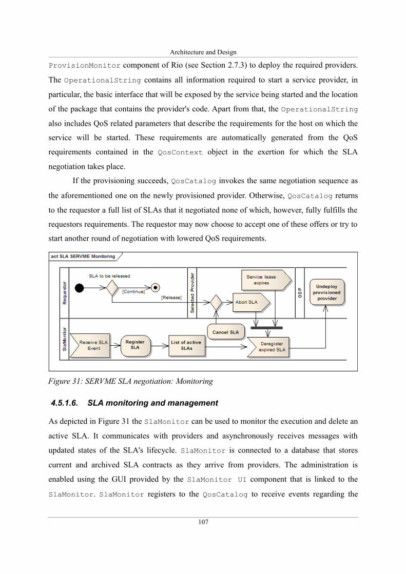
Architecture and Design
ProvisionMonitor component of Rio (see Section 2.7.3) to deploy the required providers.
The OperationalString contains all information required to start a service provider, in
particular, the basic interface that will be exposed by the service being started and the location
of the package that contains the provider's code. Apart from that, the OperationalString
also includes QoS related parameters that describe the requirements for the host on which the
service will be started. These requirements are automatically generated from the QoS
requirements contained in the QosContext object in the exertion for which the SLA
negotiation takes place.
If the provisioning succeeds, QosCatalog invokes the same negotiation sequence as
the aforementioned one on the newly provisioned provider. Otherwise, QosCatalog returns
to the requestor a full list of SLAs that it negotiated none of which, however, fully fulfills the
requestors requirements. The requestor may now choose to accept one of these offers or try to
start another round of negotiation with lowered QoS requirements.
4.5.1.6. SLA monitoring and management
As depicted in Figure 31 the SlaMonitor can be used to monitor the execution and delete an
active SLA. It communicates with providers and asynchronously receives messages with
updated states of the SLA's lifecycle. SlaMonitor is connected to a database that stores
current and archived SLA contracts as they arrive from providers. The administration is
enabled using the GUI provided by the SlaMonitor UI component that is linked to the
SlaMonitor. SlaMonitor registers to the QosCatalog to receive events regarding the
107
Figure 31: SERVME SLA negotiation: Monitoring
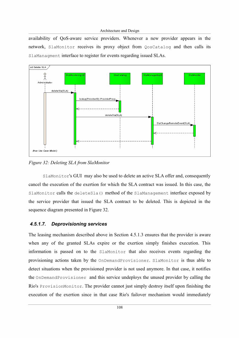
Architecture and Design
availability of QoS-aware service providers. Whenever a new provider appears in the
network, SlaMonitor receives its proxy object from QosCatalog and then calls its
SlaManagment interface to register for events regarding issued SLAs.
SlaMonitor's GUI may also be used to delete an active SLA offer and, consequently
cancel the execution of the exertion for which the SLA contract was issued. In this case, the
SlaMonitor calls the deleteSla() method of the SlaManagement interface exposed by
the service provider that issued the SLA contract to be deleted. This is depicted in the
sequence diagram presented in Figure 32.
4.5.1.7. Deprovisioning services
The leasing mechanism described above in Section 4.5.1.3 ensures that the provider is aware
when any of the granted SLAs expire or the exertion simply finishes execution. This
information is passed on to the SlaMonitor that also receives events regarding the
provisioning actions taken by the OnDemandProvisioner. SlaMonitor is thus able to
detect situations when the provisioned provider is not used anymore. In that case, it notifies
the OnDemandProvisioner and this service undeploys the unused provider by calling the
Rio's ProvisionMonitor. The provider cannot just simply destroy itself upon finishing the
execution of the exertion since in that case Rio's failover mechanism would immediately
108
Figure 32: Deleting SLA from SlaMonitor
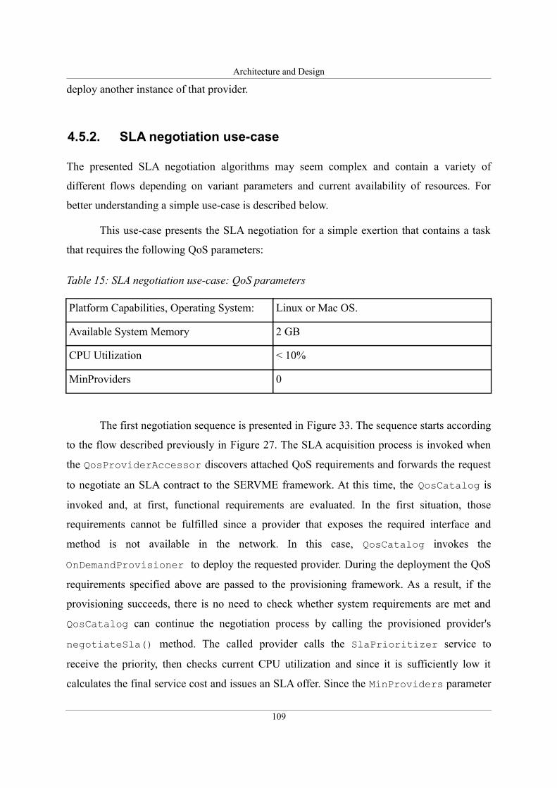
Architecture and Design
deploy another instance of that provider.
4.5.2. SLA negotiation use-case
The presented SLA negotiation algorithms may seem complex and contain a variety of
different flows depending on variant parameters and current availability of resources. For
better understanding a simple use-case is described below.
This use-case presents the SLA negotiation for a simple exertion that contains a task
that requires the following QoS parameters:
Table 15: SLA negotiation use-case: QoS parameters
Platform Capabilities, Operating System: Linux or Mac OS.
Available System Memory 2 GB
CPU Utilization < 10%
MinProviders 0
The first negotiation sequence is presented in Figure 33. The sequence starts according
to the flow described previously in Figure 27. The SLA acquisition process is invoked when
the QosProviderAccessor discovers attached QoS requirements and forwards the request
to negotiate an SLA contract to the SERVME framework. At this time, the QosCatalog is
invoked and, at first, functional requirements are evaluated. In the first situation, those
requirements cannot be fulfilled since a provider that exposes the required interface and
method is not available in the network. In this case, QosCatalog invokes the
OnDemandProvisioner to deploy the requested provider. During the deployment the QoS
requirements specified above are passed to the provisioning framework. As a result, if the
provisioning succeeds, there is no need to check whether system requirements are met and
QosCatalog can continue the negotiation process by calling the provisioned provider's
negotiateSla() method. The called provider calls the SlaPrioritizer service to
receive the priority, then checks current CPU utilization and since it is sufficiently low it
calculates the final service cost and issues an SLA offer. Since the MinProviders parameter
109
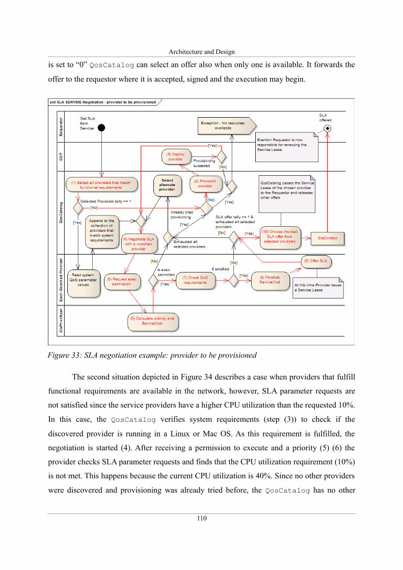
Architecture and Design
is set to “0” QosCatalog can select an offer also when only one is available. It forwards the
offer to the requestor where it is accepted, signed and the execution may begin.
The second situation depicted in Figure 34 describes a case when providers that fulfill
functional requirements are available in the network, however, SLA parameter requests are
not satisfied since the service providers have a higher CPU utilization than the requested 10%.
In this case, the QosCatalog verifies system requirements (step (3)) to check if the
discovered provider is running in a Linux or Mac OS. As this requirement is fulfilled, the
negotiation is started (4). After receiving a permission to execute and a priority (5) (6) the
provider checks SLA parameter requests and finds that the CPU utilization requirement (10%)
is not met. This happens because the current CPU utilization is 40%. Since no other providers
were discovered and provisioning was already tried before, the QosCatalog has no other
110
Figure 33: SLA negotiation example: provider to be provisioned
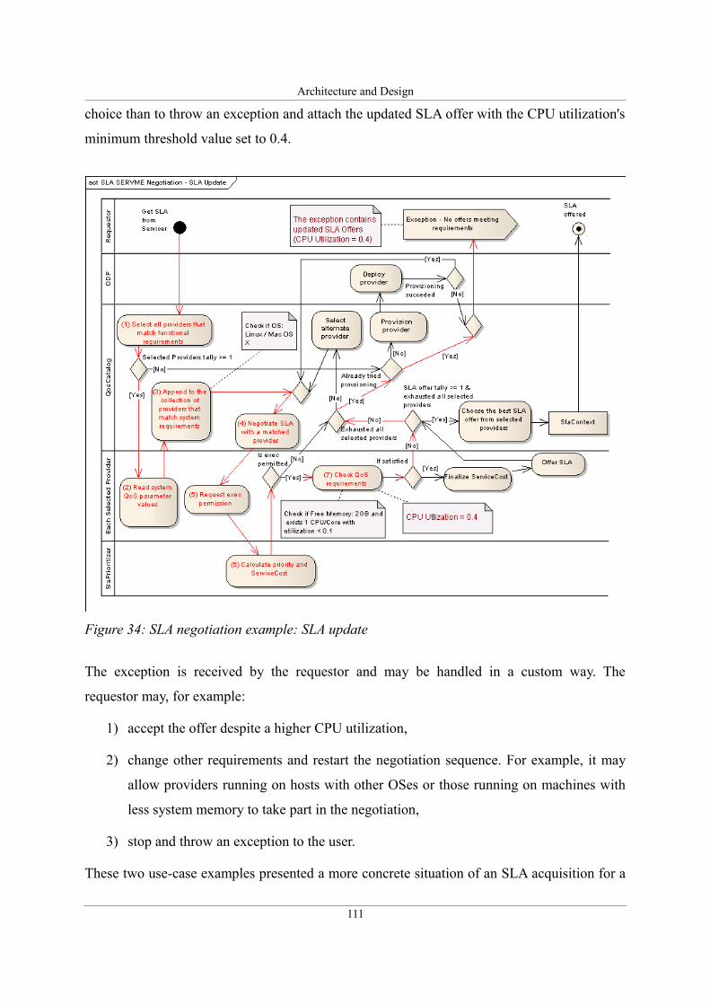
Architecture and Design
choice than to throw an exception and attach the updated SLA offer with the CPU utilization's
minimum threshold value set to 0.4.
The exception is received by the requestor and may be handled in a custom way. The
requestor may, for example:
1) accept the offer despite a higher CPU utilization,
2) change other requirements and restart the negotiation sequence. For example, it may
allow providers running on hosts with other OSes or those running on machines with
less system memory to take part in the negotiation,
3) stop and throw an exception to the user.
These two use-case examples presented a more concrete situation of an SLA acquisition for a
111
Figure 34: SLA negotiation example: SLA update
Architecture and Design
simple one task – exertion. The SLA negotiation process becomes more complicated for
composite exertions that contain multiple tasks organized in a hierarchical tree. Such cases are
described in the next sections after the following two parts that are devoted to the assignment
of priorities for exertions. Sections 4.5.3 and 4.5.4 show how prioritization may be used to
allow for a central management of resources in large installments and describe the details of
the SLA Prioritizer service that was specifically designed to handle this task within the
SERVME framework.
4.5.3. SLA prioritization as a way towards managing a cloud
using SERVME
Organizations who use distributed computing environments for concurrent engineering often
encounter problems with prioritization of tasks and their assignment to available resources.
Resources are always scarce and many computing tasks require CPU time of several hours or
even days. Therefore, it is crucial to have mechanisms that enable the prioritization of tasks
and scheduling of the availability of resources using non-functional properties to follow the
strategy created by the management.
One of the examples is a company where engineers have to prepare computing jobs for
execution before 5pm every day. At this time the management looks at the list and decides
which resources to assign to each of the jobs. This solution allows the management to control
the usage of the scarce resources and execute computing tasks according to the agreed
strategy, however, it is greatly inefficient because:
• Engineers always have to wait until 5pm even if their job would not require more than
i.e. 1 hour to accomplish.
• Resources are not evenly used throughout the day.
• It requires manual assignment of priorities.
In SERVME we want to address this problem by enabling both service requestors and service
providers – resource owners to specify non-functional parameters (nfp) – such as:
organizational position, project information or estimated time of execution.
In the proposed solution, the requestor should specify those nfp in the signature of the
request and the provider may then decide on whether to take this task or not. This decision is
112
Architecture and Design
made based on the prescheduled appointment of resources to projects or other organizational
constraints. To provide a centralized management of the corporate strategy, a component
called SlaPrioritizer is proposed.
4.5.4. SLA Prioritizer
SERVME includes the SLA Prioritizer – a component that enables a centralized
administration and management of resources based on organizational constraints. This
component provides the administrator with a graphical UI that enables to set the following
constraints:
• Prioritization rules based on organizational requirements (Project, Department, Person
responsible etc.). Example: Project “WING” is given priority X if the department
requesting the execution is A.
• Scheduling rules that define when a certain entity is allowed to execute the exertion.
Example: Department A is allowed to execute exertions between 4pm and 7pm.
• Mapping of providers and/or organizational requirements to resources – different
entities can be given access to execute certain providers on specific hosts. These
mappings may be specified in form of rules or priority thresholds that take into
account the above constraints. Example: Project “WING” is allowed to execute the
fluid dynamics calculations on hosts: Grendel and Lime.
• Cost calculation parameters – those parameter values are calculated by SLA
Priorititzer based on preconfigured rules that take into account the above constraints.
SlaPrioritizer passes these parameters back to the provider for it to calculate the
ServiceCost of the execution. Cost calculation parameters enable the administrator
to specify rules using a free market economy approach. Instead of passing to the
provider, a binary only allow/disallow command, the administrator may allow the
execution of the exertion. At the same time, the administrator can manipulate the cost
parameters to encourage or discourage the execution at certain times (scheduling) on
certain hosts (mapping to resources) or by certain entities (organizational
requirements). Example: Project WING is allowed to execute the exertion on host
Grendel between 8am and 5pm at a cost of 10 cents and between 5pm and 8am at 5
cents. On Lime project WING is always charged 8 cents.
113
Architecture and Design
SlaPrioritizer exposes the SlaPrioritization interface that is called by the
SERVME provider as the first step of the SLA negotiation process. When the QosCatalog
invokes the negotiateSla() method of the provider and passes the QoS Requirements in
form of a QosContext object, the provider extracts the OrganizationalRequirements
from QosContext and calls the SlaPrioritizer's method
getExecutionPermission(). It passes the SlaContext that contains
OrganizationalRequirements as well as functional requirements (serviceType (the
interface requested by the requestor) and the methodName) and its identification number
(ServiceID).
SlaPrioritizer calculates the priority of this execution on the basis of the received
parameters (OrganizationalRequirements, ServiceType, ServiceMethod and
ServiceID) and predefined prioritization-, scheduling- and resource mapping rules.
SlaPrioritizer returns to the provider the execution permission (allow/disallow) and the
ServiceCost parameter and in case the execution is disallowed the exception message
explaining the reasons for denying the permission to execute. In case the provider receives a
message allowing it to execute the given exertion, the SLA negotiation process proceeds to
the next step. During the service cost calculation the cost parameter supplied by
SlaPrioritizer is taken into account. Otherwise, if a disallow execution parameter is
received from SlaPrioritizer, the provider passes the exception message to the
QosCatalog and refuses to continue the negotiation process for the particular provider.
4.5.5. Composite exertions: jobs
One of the key features of SERVME is the ability to optimize the execution of jobs
according to users' preferences.
SORCER defines two basic types of jobs depending on the access/coordination
method. The first one is the PUSH type, where the job is pushed explicitly towards providers
able to perform the corresponding tasks within the job. This kind of an exertion is coordinated
by the jobber service. The second type of jobs uses the space-based computing approach
described in Section 4.5.7 and thus is coordinated by the spacer service. It is the PULL type,
114
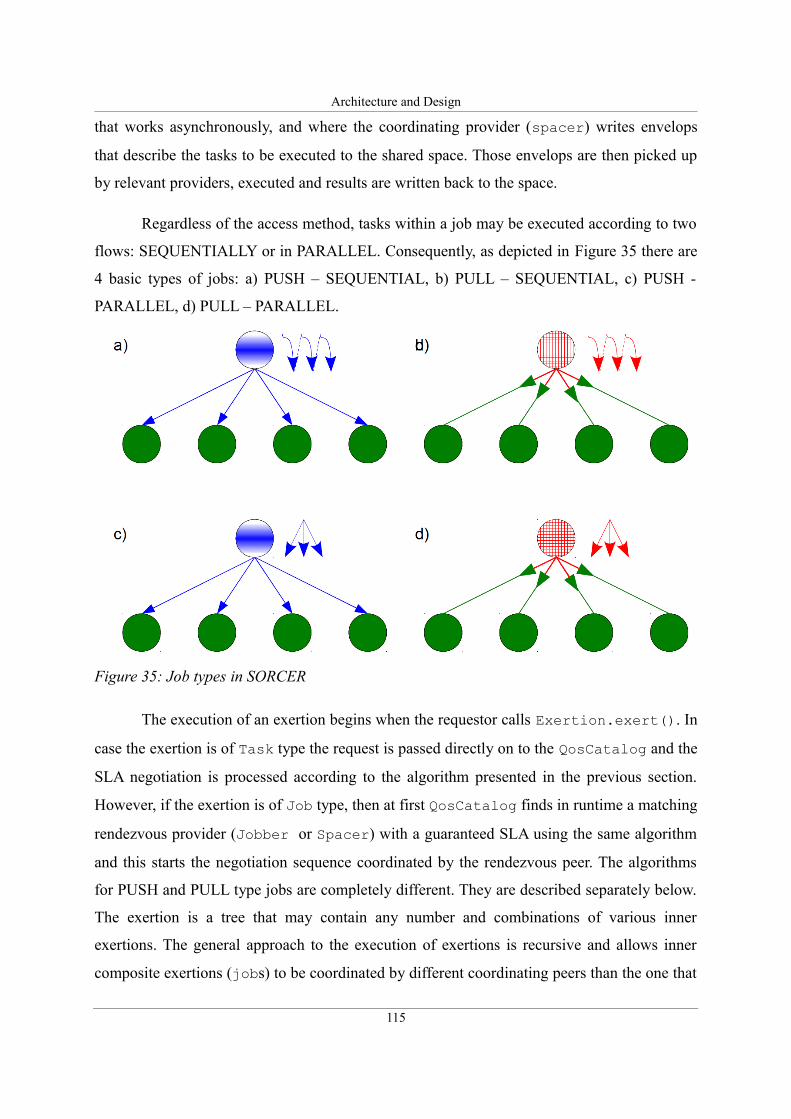
Architecture and Design
that works asynchronously, and where the coordinating provider (spacer) writes envelops
that describe the tasks to be executed to the shared space. Those envelops are then picked up
by relevant providers, executed and results are written back to the space.
Regardless of the access method, tasks within a job may be executed according to two
flows: SEQUENTIALLY or in PARALLEL. Consequently, as depicted in Figure 35 there are
4 basic types of jobs: a) PUSH – SEQUENTIAL, b) PULL – SEQUENTIAL, c) PUSH -
PARALLEL, d) PULL – PARALLEL.
The execution of an exertion begins when the requestor calls Exertion.exert(). In
case the exertion is of Task type the request is passed directly on to the QosCatalog and the
SLA negotiation is processed according to the algorithm presented in the previous section.
However, if the exertion is of Job type, then at first QosCatalog finds in runtime a matching
rendezvous provider (Jobber or Spacer) with a guaranteed SLA using the same algorithm
and this starts the negotiation sequence coordinated by the rendezvous peer. The algorithms
for PUSH and PULL type jobs are completely different. They are described separately below.
The exertion is a tree that may contain any number and combinations of various inner
exertions. The general approach to the execution of exertions is recursive and allows inner
composite exertions (jobs) to be coordinated by different coordinating peers than the one that
115
Figure 35: Job types in SORCER
Architecture and Design
coordinates the top-level job.
4.5.6. Jobs with the Push access method
SORCER introduced a recursive algorithm for handling PUSH jobs. In case of a
sequential flow the algorithm is rather simple – the jobber's built-in corresponding
dispatcher component iterates through the list of inner exertions and for each of them calls the
service() method defined in the basic Servicer interface (see Section 2.6.4). This causes
the exertion to be executed in a similar way as by calling its exert() method. Once the
execution is finished, the output context that contains the results (data) of the execution is
appended to the upper level exertion. Please note that via recursion the same service()
method is called also in case the inner the exertion is a job (of any kind). As a consequence, a
coordinating peer is searched to execute the inner job and thus the execution of this job may
be coordinated by a different rendezvous peer from the one that runs the top level job.
In case of parallel jobs, the algorithm is similar, however, the inner exertions are run
simultaneously in separate threads. The relevant dispatcher creates a table where it stores the
current states of the inner exertions. When all exertions finish, the dispatcher appends all
output contexts and returns the executed exertion to the requestor.
The introduction of QoS management in SERVME changes the flow of the execution
of all types of jobs substantially. Generally, when running with QoS the execution flow of
every task within a job is performed in two stages. The first call of the service() method
invokes the process of collecting SLA offers from providers. Only after an offer is selected,
service() is invoked again to perform the actual execution on a provider who's SLA offer
was chosen. A deeper step-by-step analysis for a simple PUSH job (Figure 35 a) or c)) is
presented below:
PUSH job with four inner tasks:
1. An exertion - job consisting of four tasks with defined QoS requirements is submitted
to the network upon the execution of the exert() method.
2. The job is picked up by a jobber and assigned a relevant dispatcher that handles
sequential or parallel jobs with QoS accordingly.
3. For each task the getSla() method is called to acquire an SLA offer using the
116
Architecture and Design
QosCatalog. The negotiation process invoked here proceeds according to the
algorithm described in Section 4.5.1. However, the offer is not directly passed to the
requestor for acceptance and signing, but instead is appended by the dispatcher to the
context of each exertion.
4. After collecting SLA offers for all inner exertions, the dispatcher calculates the total
estimated cost and time of execution of the whole top-level job and issues an SLA
offer for the job with the computed parameters. The time is accounted as the sum of
estimated execution times in case of sequential jobs or as the maximum in case of
parallel jobs. If any of the inner exertion's QoS requirements were not met and thus
among the inner SLAs there is at least one with its state set to SLA_UPDATE, the top
level SLA's state is also set to SLA_UPDATE. The offer is passed to the requestor.
5. The requestor receives the SLA offer for the top-level job as well as for inner
exertions, recursively analyzes them and decides to accept and sign the offer or reject
it.
6. Once signed, the SLA is returned to the jobber where it is recursively analyzed. This
time, however, there is no need to search for a service provider since every SLA offer
contains the proxy of the provider that issued it. As a result, its service() method is
called directly by the dispatcher to perform the actual execution. By analogy to
SORCER's PUSH job execution, parallel jobs are executed in multi threads and a
shared table is used to keep track of current states of the execution.
The proposed algorithm may be prone to some dose of criticism, for example, due to the
following issues:
– The acquisition of SLAs is performed at the very beginning (the first stage) and thus
before the exertions are executed (especially in case of a sequential flow) the
resources' usage may change significantly. The dynamic nature of environments that
are targeted by the SERVME framework does not allow to completely forecast
resource QoS parameters and thus the proposed algorithm seems to be the only way to
give estimates regarding cost and time of the execution of the whole job. PULL type
jobs are not affected by this issue since in their case SLA offers are issued and signed
and the exertions are executed independently. This allows the estimates to be more
precise since the SLA offer is always issued directly before the execution, however, it
does not provide estimates upfront. This is a significant issue as it does not allow to
117
Architecture and Design
perform a full multiobjective optimization (see Section 4.5.9) before the selection of
particular SLA offers.
– Since resources are allocated for the whole job, SLA offers can be issued only for jobs
that can completely “fit” onto available resources. That is, there must be enough
resources to be allocated at the same time for all exertions within this job. For
example, for a job that contains 10 tasks where every task needs 250 MB of free
system memory there must be minimally 2500 MB available in the environment for all
SLA contracts to be issued without updated offers. This problem results from the fact
that SERVME unlike most grid schedulers does not perform scheduling. This may be
regarded as a problem, however, on the other hand it guarantees a quick execution
since there is no need to wait for resources to become free. In case of very large jobs
that cannot be “fitted” onto available resources at once, the PULL type jobs are
recommended because they are based on different assumptions and thus are not
affected by this issue.
To conclude, PUSH jobs are executed in two stages. Due to their nature they are best suited to
run small jobs that require a quick execution of the whole job and they provide estimates of
cost and time of the execution of the whole job prior to the execution. Due to the dynamic
nature of resources the estimates may not be very exact, however, they allow to perform a
multiobjective optimization where a set of SLA offers is chosen to run the job as fast as
possible but at a constraint cost or the opposite.
Before presenting the algorithms for running PULL type jobs it is crucial to describe
the concept of space-based computing that is used to coordinate the execution of PULL jobs.
4.5.7. Space-based computing
Space-based computing is also known as tuple space computing. It constitutes a model of
concurrent programming used in distributed systems. Tuple Spaces were introduced by David
Gelerntner in the paper entitled “Generative Communication in Linda” [115] that was
published in 1985. Gelerntner created a programming language called Linda in which he
implemented the concept of tuple spaces. As he writes in [115], “Linda’s unusual features
make the language suggestive and interesting in its own right. Where most distributed
118
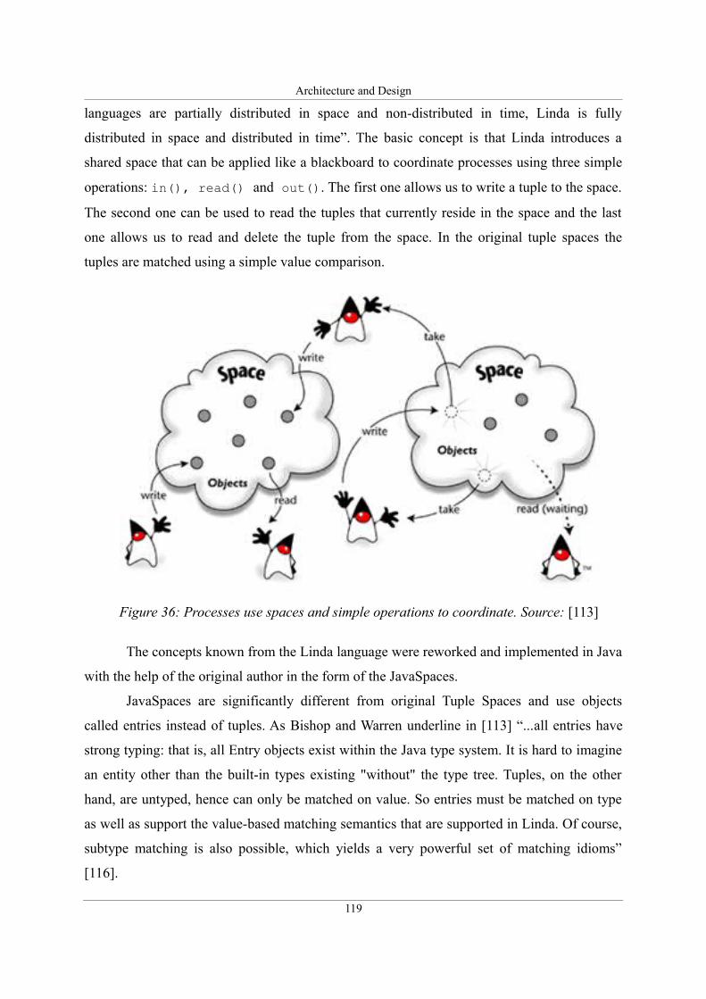
Architecture and Design
languages are partially distributed in space and non-distributed in time, Linda is fully
distributed in space and distributed in time”. The basic concept is that Linda introduces a
shared space that can be applied like a blackboard to coordinate processes using three simple
operations: in(), read() and out(). The first one allows us to write a tuple to the space.
The second one can be used to read the tuples that currently reside in the space and the last
one allows us to read and delete the tuple from the space. In the original tuple spaces the
tuples are matched using a simple value comparison.
The concepts known from the Linda language were reworked and implemented in Java
with the help of the original author in the form of the JavaSpaces.
JavaSpaces are significantly different from original Tuple Spaces and use objects
called entries instead of tuples. As Bishop and Warren underline in [113] “...all entries have
strong typing: that is, all Entry objects exist within the Java type system. It is hard to imagine
an entity other than the built-in types existing "without" the type tree. Tuples, on the other
hand, are untyped, hence can only be matched on value. So entries must be matched on type
as well as support the value-based matching semantics that are supported in Linda. Of course,
subtype matching is also possible, which yields a very powerful set of matching idioms”
[116].
119
Figure 36: Processes use spaces and simple operations to coordinate. Source: [113]
Architecture and Design
More details regarding JavaSpaces are provided by Freeman, Hupfer, and Arnold in
[117]. They define the space as a “...shared, network-accessible repository for objects.” The
authors explain the basic mechanisms: “Processes use the repository as a persistent object
storage and exchange mechanism; instead of communicating directly, they coordinate by
exchanging objects through spaces. As shown in Figure 36, processes perform simple
operations to write new objects into a space, take objects from a space, or read (make a copy
of) objects in a space. When taking or reading objects, processes use a simple value-matching
lookup to find the objects that matter to them. If a matching object isn't found immediately,
then a process can wait until one arrives. Unlike conventional object stores, processes don't
modify objects in the space or invoke their methods directly – while there, objects are just
passive data. To modify an object, a process must explicitly remove it, update it, and reinsert
it into the space. “ [117].
A simple implementation of the JavaSpaces is provided in the Jini distributed
computing framework (see Section 2.6.2), however, many more powerful implementations
exist that share the same API but provide greater scalability and more functionality, for
example: persistence and advanced administration GUIs are available in the Blitz project
[118].
4.5.8. Jobs with the Pull access method
SORCER uses JavaSpaces as a way to handle the coordination of large exertions: jobs that
contain multiple tasks. The asynchronous nature of space computing and its ability to
efficiently manage resources in a simple way fit well to the concept of disconnected (late-
binding) execution of exertions that forms one of the basic assumptions introduced in the
SORCER MOS.
The basic handling of PULL type jobs in SORCER (without QoS) consists of the
following steps. The spacer service analyzes the job and for every inner exertion (both
tasks and jobs) it creates an envelop object that describes the exertion to be executed.
According to the principles of JavaSpaces the envelop must subclass the basic Entry type
and have publicly accessible fields that are used to match against templates in the space. The
fields used for matching contain the required provider's service type (interface), optionally the
120
Architecture and Design
provider's name and a flag that defines the current state of the execution. This envelop is
dropped to the space, where it is matched against templates prepared previously by service
providers. Those templates contain the names of interfaces offered by them and the state of
the execution set to “waiting for provider”. This allows service providers to receive from the
space exertions that they are able to execute. Whenever the envelop matches the template, it is
taken from the space by the provider that owned the matched template to avoid a situation
where a different provider executes the same exertion simultaneously. When the execution is
finished the envelop is written back to the space by the provider but its state is updated to
allow the spacer coordinating peer to match the executed envelops. Spacer collects envelops
of executed exertions and returns the results to the requestor.
However, it may seem simple, the algorithms used to coordinate the execution of
PULL jobs are in reality far more complicated due to the requirements of robustness and thus
the introduction of transactional semantics as well as security. These issues, however, were
already addressed in previous research, for example in [119].
The introduction of SLA-based QoS management to the execution of PULL type jobs
substantially changes the assumptions and the control flow of the execution of PULL type
jobs. In this case, the space is also used to match exertions to service providers that are able to
execute them. However, the space is only used during the first stage when SLA offers are
acquired and the actual execution (the second stage) is invoked directly by the spacer service.
Consequently, the execution does not pass through the space. This change has many
implications on the coordination algorithms, the details of which are presented later in this
section after a higher-level overview of the SLA acquisition and negotiation process.
4.5.8.1. SLA negotiation in space computing
An overview of the SLA negotiation process for jobs with a PULL access method is presented
in Figure 37. The control flow illustrated in this diagram starts when the top-level exertion
(PULL job) is executed by the requestor and is passed to the Spacer service for coordination.
Spacer selects independent inner exertions (1) and for every one of them creates an SLA
envelop (described in details in Section 4.5.8.5) and writes it to the space (2). SLA envelops
are matched against templates created earlier by service providers. Those providers that can
fulfill functional requirements (offer the requested service type) read the corresponding
envelops (3) and start the process of issuing an SLA offer. At first they call the
121
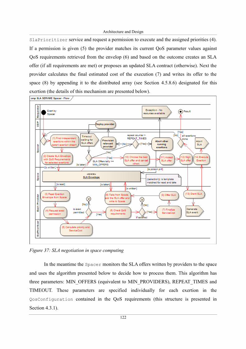
Architecture and Design
SlaPrioritizer service and request a permission to execute and the assigned priorities (4).
If a permission is given (5) the provider matches its current QoS parameter values against
QoS requirements retrieved from the envelop (6) and based on the outcome creates an SLA
offer (if all requirements are met) or proposes an updated SLA contract (otherwise). Next the
provider calculates the final estimated cost of the execution (7) and writes its offer to the
space (8) by appending it to the distributed array (see Section 4.5.8.6) designated for this
exertion (the details of this mechanism are presented below).
In the meantime the Spacer monitors the SLA offers written by providers to the space
and uses the algorithm presented below to decide how to process them. This algorithm has
three parameters: MIN_OFFERS (equivalent to MIN_PROVIDERS), REPEAT_TIMES and
TIMEOUT. These parameters are specified individually for each exertion in the
QosConfiguration contained in the QoS requirements (this structure is presented in
Section 4.3.1).
122
Figure 37: SLA negotiation in space computing
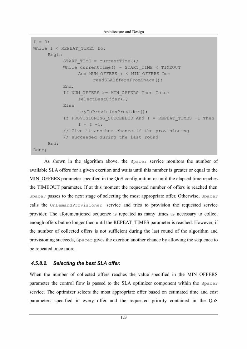
Architecture and Design
As shown in the algorithm above, the Spacer service monitors the number of
available SLA offers for a given exertion and waits until this number is greater or equal to the
MIN_OFFERS parameter specified in the QoS configuration or until the elapsed time reaches
the TIMEOUT parameter. If at this moment the requested number of offers is reached then
Spacer passes to the next stage of selecting the most appropriate offer. Otherwise, Spacer
calls the OnDemandProvisioner service and tries to provision the requested service
provider. The aforementioned sequence is repeated as many times as necessary to collect
enough offers but no longer then until the REPEAT_TIMES parameter is reached. However, if
the number of collected offers is not sufficient during the last round of the algorithm and
provisioning succeeds, Spacer gives the exertion another chance by allowing the sequence to
be repeated once more.
4.5.8.2. Selecting the best SLA offer.
When the number of collected offers reaches the value specified in the MIN_OFFERS
parameter the control flow is passed to the SLA optimizer component within the Spacer
service. The optimizer selects the most appropriate offer based on estimated time and cost
parameters specified in every offer and the requested priority contained in the QoS
123
I = 0;While I < REPEAT_TIMES Do:
BeginSTART_TIME = currentTime();While currentTime() - START_TIME < TIMEOUT
And NUM_OFFERS() < MIN_OFFERS Do:readSLAOffersFromSpace();
End;If NUM_OFFERS >= MIN_OFFERS Then Goto:
selectBestOffer();Else
tryToProvisionProvider();If PROVISIONING_SUCCEEDED And I = REPEAT_TIMES -1 Then
I = I -1; // Give it another chance if the provisioning// succeeded during the last round
End;Done;
Architecture and Design
requirements for a given exertion. This selection may be performed according to one
parameter (the shortest time or the lowest cost) or it may involve multiobjective optimization
(the shortest time at constrained cost or vice-versa), however, in case of PULL type jobs a full
upfront multiobjective optimization is not possible as it undermines the basic assumption of
asynchronous operation and time independence of PULL type jobs. More discussion
regarding the optimization algorithms is provided in Section 4.5.9.
4.5.8.3. Leasing SLA offers.
The SERVME framework uses a leasing mechanism to avoid blocking resources
unnecessarily as well as a distributed garbage collector. In case of PULL type jobs, the
mechanism is designed in the following way. A Lease is created when a service provider
issues an SLA offer. This lease has a fixed timeout. The offer is written to the space. When it
is collected by the Spacer service it is immediately passed to a lease renewal service which
takes care of extending the Lease automatically until it is released or the service is disposed.
When offers are collected and the Spacer selects the best one, its Lease is extended while all
other ones are canceled allowing resources allocated for these SLA offers to immediately
become free.
The Lease for the chosen offer is monitored and extended by the renewal service for
the whole duration of the exertion's execution that begins shortly after the selection of the
SLA offer.
4.5.8.4. SLA acceptance, signing and execution.
The question of SLA acceptance and signing was discussed extensively. Generally, this step
should be performed by the service requestor, however, in case of PULL jobs such behavior
would impose a lot of communication overhead needed to asynchronously pass the selected
SLA offers to the requestor for acceptance and signing. Furthermore, the communication
model imposed by the federated method invocation does not allow to communicate with the
requestor without stopping the control flow of the entire exertion and passing it to the
requestor. This implies that in such case the signing would require Spacer to collect and
select offers for the whole top-level exertion and only then pass them to the requestor for
acceptance and signing. This behavior, however, would completely oppose the most crucial
assumptions of PULL type jobs: disconnected and asynchronous operation. As a result, it is
124
Architecture and Design
proposed to allow the Spacer service to perform the signing of SLA offers on behalf of the
requestor. However, this implies that it may only occur if the offer completely fulfills the QoS
requirements specified by the requestor.
Spacer accepts and signs chosen SLA offers independently for each exertion
immediately after selecting it. Then the SLA is sent to the issuing service provider and the
exertion's service() method is called to start the execution.
When the execution is finished the Spacer collects the results and reads the actual
execution cost and time and uses it to calculate the final execution cost and time for the whole
top-level exertion.
During the whole process of the SLA acquisition and execution the Spacer monitors
the current states of all exertions and in case of any failure suspends the execution of the
whole top-level job. In this case SLA envelops are taken from the space, collected SLA offers
are aborted and all other offers that may still reside in the space are discarded when their
initial, fixed time Leases timeout.
When the execution of all inner exertions finishes the Spacer collects the results,
calculates the actual overall time and cost of the execution and returns the results and the
control flow to the requestor.
4.5.8.5. SLA envelops
The SLA Envelop created for each exertion and written to the space contains the following
information:
1) exertion ID,
2) SLA contract (requirements or offer),
3) SLA state,
4) service type (requested provider's interface),
5) provider's name.
When the envelop is written to the space its SLA state is set to SLA_REQUEST. Every service
provider creates sets of two templates to match requests for SLA offers for every service type
(interface) that it can offer. Each of those templates contains the offered service type and the
SLA state set to SLA_REQUEST. However, one of them also has a fixed provider's name and
the other has a provider name set to null. This allows service providers to receive SLA offer
125
Architecture and Design
requests both for exertions designated only to a certain group of named service providers as
well as for all those exertions that do not specify names of the service provider required for
the execution.
4.5.8.6. Distributed arrays in space
As opposed to the algorithm of exerting non-QoS exertions via space proposed in SORCER
that uses independent entries (exertion envelops) in the space, the SLA acquisition and
negotiation algorithm in SERVME needs to store collections of entries in the space. This
requirement is a result of the fact that for every SLA offer request written to the space by the
Spacer service there may be any number of SLA offers and the ability to determine their
current number without reading all these objects from the space is crucial. Taking into account
the shared nature of the space, this structure must be carefully designed to disallow concurrent
changes, while allowing to be viewed and its size to be read simultaneously. This structure
called a distributed array is proposed in SERVME. The distributed array is an extended
pattern based on the structure by the same name proposed by F. Freeman et al. in [117].
A distributed array defines two classes of entries—entries that hold meta-information
about the array (its size, next open position, and so on) and entries that hold the data elements
of the array. [117]. When the array is created it only contains the start and end element. All
elements are linked by having a common field that contains the name of the array. If any
participant wants to add an element to the array, it takes the end of the array from the space,
thus blocking others from doing the same thing simultaneously, creates a new element,
updates the end's position and writes it back to the space. Elements can only be deleted from
the beginning of the array or at the end. At any moment the size of the array can be calculated
as the difference between the position of the end element and the start element.
SERVME extends the basic distributed array pattern by allowing multiple elements to
be taken from the array as well as fixes some issues with transactional handling of the arrays.
During the SLA negotiation process the Spacer service creates two distributed arrays
for every SLA offer request written to the space. To allow the arrays to be easily identified
their names contain the exertion's identification number appended to the fixed string:
“OFFERS” or “UPDATES”. The names of the arrays suggest their purpose. One of them is
designated for SLA offers issued by service providers and the other one is meant for offers
that do not completely fulfill QoS requirements and thus contain SLA offers with updated
126
Architecture and Design
SLA parameter values.
Service providers append their offers to the corresponding arrays depending on the
state of their offer. The Spacer service monitors the size of the array that contains SLA offers
and takes them from the space. When the number of collected offers reaches the required
number specified in the MIN_OFFERS parameter or when a timeout event occurs both arrays
are read from space and deleted.
4.5.9. Discussion on job execution optimization
Previous sections introduced the three basic elements required for the SLA management of
exertions: the (1) SLA model, the (2) negotiation protocol in form of the communication
model that contains defined interfaces and the (3) SLA negotiation algorithms. However, little
attention was paid to issues related to the optimization of the execution of exertions. These
aspects are discussed here and special notice is given to multiobjective optimization (MOO) of
composite exertions (jobs) that occurs when the goal is to execute a given job at the lowest
possible cost while keeping the execution time within a certain limit or the opposite, that is,
when it is required to shorten the execution time while keeping the cost within a certain range.
First a formal definition is given in the section below, then some research problems are
identified that require further methods presented in Section 4.5.9.3. Finally, Section 4.5.9.4
contains a discussion of the applicability of MOO to the execution of exertions depending on
their type and structure of the exertion's tree.
4.5.9.1. Multiobjective optimization – formal definition and algorithms
To illustrate the problem mentioned above formally we will start with a concrete example and
formulate the general problem later.
For this example, it is assumed that there is a job that consists of two inner exertions
(tasks), and for each of those tasks three SLA offers were received from service providers.
Every given SLA offer contains the estimated cost and time parameters. The goal is to find the
most optimal combination of two SLA offers, one for each of those tasks, that will minimize
the cost while keeping the total execution time below a certain constraint. The tasks in this
example will be executed sequentially.
127
Architecture and Design
This problem is illustrated below. There are four parts of the formula. The first part
specifies the SLA offers, the second part the design variables and the objective function and
finally, parts 3) and 4) show constraints of the optimization formula.
1) The parameters that characterize the SLA offers for tasks within the analyzed job form
pairs that can be defined as:
SLA offers for Task1: [c11
t11 ] ,[c12
t 12 ] ,[c13
t 13 ] , SLA offers for Task2: [c21
t 21 ] ,[c22
t 22 ] , [c23
t 23 ] ,
where in [c ij
t ij ] , c ij is the estimated cost for task i in offer j, and t ij is the estimated execution
time for task i in offer j.
Generally, the formula for the SLA offers of the k exertion within the job that contains k inner
exertions and for every inner exertion there are l number of offers is the following:
SLA Offers for k exertion: [ck1
t k1 ] ,[c k2
t k2 ] ,... ,[ckl
t kl ]2) The design variables are the parameters that decide which offer to choose for every task.
In the given example the objective is to MINIMIZE the total cost presented in the following
expression:
min f x ij=TotalCost=x11×c11+x12×c12 +x13×c13 +x21×c21+x22×c22+x23×c23
Generally for a cost optimization this equation can be defined as:
min f x ij=TotalCost=∑i=1
i=k
∑j=1
j=l
x ij×c ij , where k – number of tasks in the job and l – number
of offers for each of the tasks.
In case of a time optimization the design variables are generally defined as:
min f x ij=TotalExecTime=∑i=1
i=k
∑j=1
j=l
x ij×t ij ,
3) Since tasks will be executed sequentially the constraint that expresses the desired
128
Architecture and Design
maximum execution time is the following:
Constraint : x11× t11+x12×t12+x13×t13+x21×t21 +x22×t22+x23×t23≤TotalExecTime ,
thus generally for a cost optimization:
Constraint :∑i=1
i=k
∑j=1
j=l
x ij×t ij≤TotalExecTime , where k – number of tasks in the job and l –
number of offers for each of the tasks or for a time optimization:
Constraint :∑i=1
i=k
∑j=1
j=l
x ij×c ij≤TotalCost
In case of a parallel execution this constraint would have to be reformulated into several
independent equations, for example:
Constraint : x11× t11+x12×t 12+x13×t 13≤TotalExecTime and
Constraint : x21×t21+x22×t22 +x23×t23≤TotalExecTime
and thus generally there would be k equations, one for each of the tasks. In case of a cost
optimization every one of them would be defined as:
Constraint :∑j=1
j=l
xkj×tkj≤TotalExecTime
or in case of time optimization:
Constraint :∑j=1
j=l
xkj×ckj≤TotalCost
4) Finally, the last set of constraints should ensure that there is exactly one offer chosen for
each task. These constraints may be defined in various ways depending on the type of
algorithm that will be applied. Generally, the requirement is that for each of the k inner
exertions:
Constraint k :∑j=1
j=l
x kj=1 and x kj∈[0,1] .
129
Architecture and Design
The last constraint suggests the types of algorithms that may be applied to solve the
MOO problem defined here. As a result, linear programming techniques such as the simplex
method cannot be applied since they do not allow design variables to be discrete. The defined
problem can be classified as a discrete linear programming problem and solved using integer
programming algorithms or branch and bound techniques. The last group of algorithms is
widely described in the literature, for example, a survey on applications of branch and bound
was presented by Lawler and Wood in [120]. Various applications of these methods were
described in [121] and [122] and more recent extensions that focus on discrete linear
problems include [123], for example. Apart from branch and bound techniques it is also
possible to solve the aforementioned problem using nonlinear programming by formulating
the last requirement as:
Constraint i :∑j=1
j=l
x ij2=1
This last approach was taken for the validation of the SERVME framework. Positive
previous experience with the application of the nonlinear techniques and, in particular, the
CONMIN optimizer encouraged the author to follow this approach. The algorithm used by the
CONMIN optimizer was first presented by Shanno and Phua in [124] and [125]. The
CONMIN optimizer used in SERVME uses the Fortran code developed by NASA and
documented in [126] and [127].
When using the nonlinear approach the last group of constraints for the described
example should be defined as:
Con1 : x11 x12 x13=1 , Con2 : x112 +x12
2 +x132=1 ,
Con3 : x21x22x23=1 , Con4 : x212 +x22
2 +x232=1
The selection of a nonlinear technique instead of discrete linear programming methods
may expose this work on the SERVME framework to some dose of criticism. Therefore, it is
important to explain that this decision was made purposefully. The selection of the best
optimization algorithm is by itself a substantial research problem that requires not only a
broad knowledge of available techniques but also extensive work required to test the practical
applicability and performance of potential optimization algorithms. Such research is regarded
as one of the future directions and follow-ups of this dissertation. The SERVME framework
130
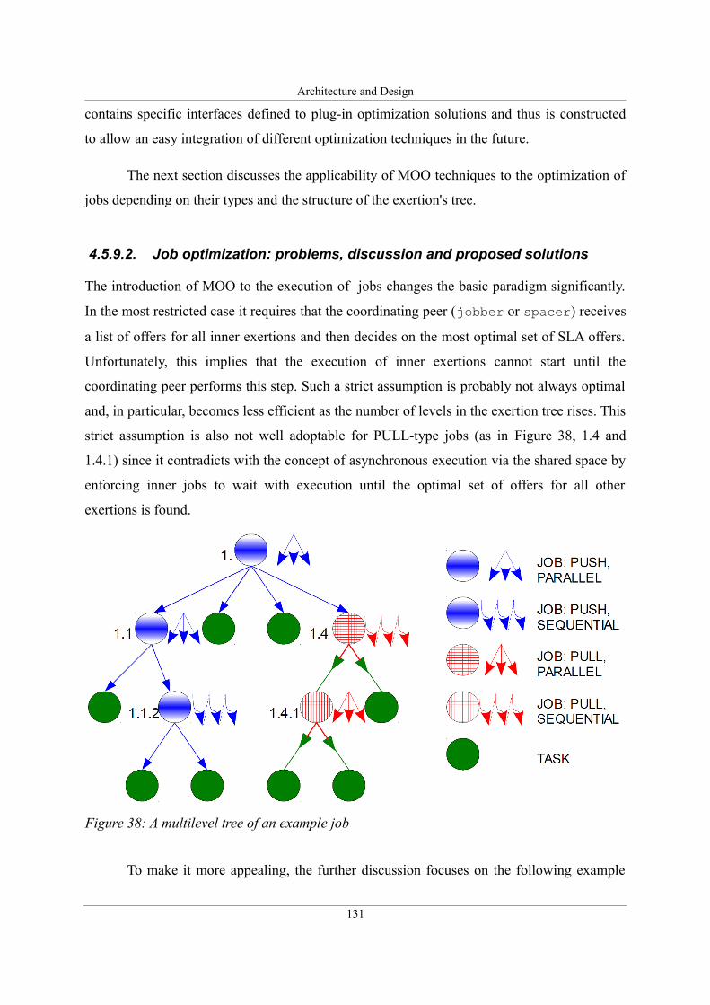
Architecture and Design
contains specific interfaces defined to plug-in optimization solutions and thus is constructed
to allow an easy integration of different optimization techniques in the future.
The next section discusses the applicability of MOO techniques to the optimization of
jobs depending on their types and the structure of the exertion's tree.
4.5.9.2. Job optimization: problems, discussion and proposed solutions
The introduction of MOO to the execution of jobs changes the basic paradigm significantly.
In the most restricted case it requires that the coordinating peer (jobber or spacer) receives
a list of offers for all inner exertions and then decides on the most optimal set of SLA offers.
Unfortunately, this implies that the execution of inner exertions cannot start until the
coordinating peer performs this step. Such a strict assumption is probably not always optimal
and, in particular, becomes less efficient as the number of levels in the exertion tree rises. This
strict assumption is also not well adoptable for PULL-type jobs (as in Figure 38, 1.4 and
1.4.1) since it contradicts with the concept of asynchronous execution via the shared space by
enforcing inner jobs to wait with execution until the optimal set of offers for all other
exertions is found.
To make it more appealing, the further discussion focuses on the following example
131
Figure 38: A multilevel tree of an example job
Architecture and Design
depicted in Figure 38. This is a three-level PUSH type exertion (1.) that contains both PUSH
(1.1 and 1.1.2) and PULL (1.4 and 1.4.1) inner exertions.
Research questions:
There are the following questions to answer in this example:
1. Job 1.1.2 and 1.4 are sequential, does it make sense to use MOO in those cases? MOO
implies waiting for SLA offers for subtasks (in case of 1.1.2 those will be tasks 1.1.2.1
and 1.1.2.2) then choosing the optimal set of offers and then starting the execution.
The problem is: since it is a sequential execution, before task 1.1.2.2 starts to execute
task 1.1.2.1 has to finish and in the meantime the circumstances may change causing
the previously chosen SLA offer for task 1.1.2.2 to be invalid. Would not an
incremental optimization be better in this case?
2. Job 1. is parallel and of PUSH type and thus seems to be ideal for MOO, however, it
contains inner jobs. SORCER and SERVME use an algorithm where hierarchical inner
jobs are executed in the same manner as any other exertions, that is the service()
method of those jobs is called and they may be picked up by any Jobber/Spacer
provider (not necessarily the same one as the one that executed the top-level job). This
implies that the top-level Jobber receives only the final SLA offer to be signed before
starting the execution. A complete MOO would mean that the upper-level Jobber
(running job 1.) would receive a set of offers for all subtasks of inner jobs (tasks
1.1.2.1 and 1.1.2.2, task 1.1.1, job 1.1.2 and job 1.1 etc.) then it would use the MOO
algorithm to choose the optimal set of offers, accept them and, finally, allow them to
execute. This leads to other research questions:
1. Does it at all make sense to descend down the tree and thus make the inner jobs
dependent from the top-level one delegating all decisions of choosing the optimal
offers to the Jobber running the top-level job?
2. It seems that for any multiple level jobs (having any number of inner levels) it is
not optimal to allow the complete MOO thus the question arises how many levels
should be taken into account and how the number of levels taken for MOO
depends on the types of inner jobs (PARALLEL vs. SEQUENTIAL, PUSH vs.
PULL) ?
A deeper analysis of the aforementioned problems leads to the introduction of a new
132
Architecture and Design
optimization method that is developed as a variation of the MOO described in Section
4.5.9.1.
4.5.9.3. Incremental multiobjective optimization methods
The Incremental Multiobjective Optimization (IMOO) is proposed as an extension of the
MOO that may be applied for specific cases. IMOO uses the same sets of algorithms and is
formally defined similarly to the MOO described in Section 4.5.9.1. However, the IMOO
analyzes only SLA offers for the current exertion assuming previously chosen SLA offers for
exertions at the same level in the tree as granted and, consequently treats their time and cost
parameters as constant values in the objective function and constraint equations. This
simplified algorithm allows us to avoid creating deep dependencies between exertions on
different levels of the tree within a job. This optimization method should be used for
multilevel PUSH type jobs.
The most simplified optimization method that follows the IMOO approach should be
introduced for running jobs with the PULL access method. The asynchronous and
disconnected nature of jobs coordinated using the space-based computing approach does not
allow us to use a complete MOO. However, even the IMOO as described above, would
require the exertions to wait with starting the execution until SLA offers are collected for all
tasks on the same level within the PULL type job. As a consequence, the proposed solution is
to bring the IMOO down to the level of a single task. This would imply that the analysis of
SLA offers for the particular task would be pursued using the MOO algorithms while taking
as granted the currently available data about selected SLA offers for other exertions within the
same job. This method will be called Incremental Task-Level Multiobjective Optimization
(ITMOO).
This approach is especially reasonable for SEQUENTIAL PULL type jobs since it
simply means that the MOO technique is used to select the best offer for each task within the
job without waiting to receive SLA offers for exertions that are further in the job's sequence
but taking into account the cost and time parameters of previously chosen SLA offers for
exertions that were executed prior to the currently analyzed exertion. An illustration of this
situation is given in Figure 39. In this example the tasks are executed sequentially in the order
depicted by their numbers.
133
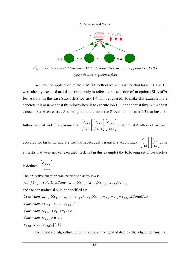
Architecture and Design
To show the application of the ITMOO method we will assume that tasks 1.1 and 1.2
were already executed and the current analysis refers to the selection of an optimal SLA offer
for task 1.3. In this case SLA offers for task 1.4 will be ignored. To make this example more
concrete it is assumed that the priority here is to execute job 1. in the shortest time but without
exceeding a given cost c. Assuming that there are three SLA offers for task 1.3 that have the
following cost and time parameters: [c1.3-1
t1.3-1 ] ,[c1.3-2
t 1.3-2 ] ,[c1.3-3
t 1.3-3 ] and the SLA offers chosen and
executed for tasks 1.1 and 1.2 had the subsequent parameters accordingly: [c1.1
t1.1 ] , [c1.2
t1.2 ] . For
all tasks that were not yet executed (task 1.4 in this example) the following set of parameters
is defined: [c future
t future ]The objective function will be defined as follows:
min f x ij=TotalExecTime=x1.3-1×t1.3-1 +x1.3-2×t1.3-2 +x1.3-3× t1.3-3
and the constraints should be specified as:
Constraint 1: x1.3-1×c1.3-1 +x1.3-2×c1.3-2 +x1.3-3×c1.3-3c1.1c1.2c future≤TotalCost
Constraint 2: x1.3-1x1.3-2 x1.3-3=1
Constraint 3:cfuturec1.1c1.2c
Constraint 4: cfuture0 and
x1.3-1 , x1.3-2 , x1.3-3∈[0,1]
The proposed algorithm helps to achieve the goal stated by the objective function,
134
Figure 39: Incremental task-level Multiobjective Optimization applied to a PULL
type job with sequential flow
Architecture and Design
however, it does not guarantee that the constraint that presents the Total Cost of the execution
of the whole job ( c ) will not be breached since for any task other than the last one (1.4) the
cost of tasks still not executed (the future cost: cfuture) is not known. As a result, it may happen
that at the time SLA offers are analyzed for the last task (1.4), for example, the remaining
amount of money (difference between the cost constraint c and the sum of cost parameters for
all already executed exertions) is smaller than the least expensive SLA offer for that task.
The described deficiency of the ITMOO method is regarded as a proposed
compromise between achieving the goal of selecting the most optimal set of SLA offers for all
inner exertions of a PULL type job and allowing the inner exertions to be executed in a
dynamic asynchronous and independent way.
Certainly, the proposed incremental optimization methods open new research
problems that cannot be fully addressed in this work and should be regarded as future
directions.
4.5.9.4. Proposed optimization methods for different types of jobs
Taking into account the research problems listed in Section 4.5.9.2 as well as proposed
optimization methods MOO described in Section 4.5.9.1 and IMOO and ITMOO presented in
Section 4.5.9.3, it is possible to formulate general rules and recommendations for the
execution of any given types of composite exertions. The following points summarize the
proposed solution:
1. Use the complete MOO only for PUSH, (both PARALLEL and SEQUENTIAL) jobs
that contain only tasks (no inner jobs).
2. If a PUSH job contains both tasks and jobs use IMOO to select SLA offers for all tasks
taking into account the offers for inner jobs as granted and thus allowing these
exertions to be executed independently.
3. In case of PULL type jobs use ITMOO to allow all tasks within the job to be executed
asynchronously.
The job depicted in Figure 38 on page 131 is used as an example to illustrate the
aforementioned recommendations. A list of steps that describe the optimization methods used
during the execution of this exertion is presented below:
1. For job 1. use IMOO to select SLA offers for tasks 1.2 and 1.3.
2. Assuming chosen offers for tasks 1.2 and 1.3 as granted choose the best offer for
135
Architecture and Design
exertion 1.1 or 1.4 (whichever one supplies a set of offers first), perform the same for
the remaining other exertion (1.1 or 1.4).
3. For all PULL type of jobs (1.4 and 1.4.1) use ITMOO.
4. If the QoS requirements specify only one criteria (the best time / the lowest cost) then
use a simpler optimization technique, that is, decide on the offer while analyzing
offers for each task individually (without returning the list of SLA offers to
jobber/spacer).
The presentation of the applicability of proposed optimization methods to different types of
jobs depending on their access method (PUSH or PULL), flow (SEQUENTIAL or
PARALLEL) and position within the top-level exertion's tree concludes the section devoted to
job execution optimization. This section formally described the problem of multiobjective
optimization, proposed different optimization methods, encouraged the use of certain
algorithms and last but not least, discussed the problems that still remain open and should be
regarded as future research areas.
4.6. Summary
Chapter 4 presents the architecture and the design of the proposed resource management
framework. Following a short introduction, Section 4.1 described the methodology, tools and
techniques used during the design phase of the framework. Section 4.2 presented the
conceptual architecture of the proposed solution and explained the basic assumptions that
influenced the design decisions made at later stages. The discussion of the conceptual
architecture revealed the main research areas that were described in the following sections.
The first of them: Section 4.3 presented the QoS/SLA model, the next one – Section 4.4
proposed the component architecture and last but not least, Section 4.5 introduced the
interactions within the SERVME framework. It is worth mentioning that the last section
contains a description of the whole SLA negotiation process in many different scenarios. It
presents the details of proposed algorithms for the negotiation and optimization of the
execution of exertions within the federated environment. In particular, this part includes the
presentation of multiobjective optimization techniques used to optimally execute composite
exertions.
136
Validation
Chapter 5. Validation
However beautiful the strategy, you should occasionally look at the results.
Sir Winston Churchill
Computer science is a practical domain. Its goal is to create solutions that can be applied to
solve real world problems in an efficient way. As a result, it is not enough to address the
problem defined here as “creating a solution that allows us to optimally allocate resources in
federated metacomputing environments” by defining the conceptual architecture and
proposing models such as the SLA model or various algorithms related to SLA negotiation or
efficient execution of metaprograms. It is required to validate the proposed solution and show
how the SERVME framework's architecture and algorithms address the issues defined in the
requirements analysis in practical deployments.
This chapter describes the validation of the proposed SERVME framework. At first
various approaches to software validation techniques are presented. The next sections follow
the R.G. Sargent's approach that includes conceptual and operational validation. Section 5.2
focuses on the conceptual validity and shows the model of classes and packages and presents
the technical architecture. Section 5.3 concentrates on the operational part that includes the
validation of use-cases, performance analysis and the measurement of the overhead time
bound to SLA management.
This chapter does not include the validation of the SLA Prioritizer component (see
Sections: 4.5.3 and 4.5.4) and does not describe use-cases that involve multiobjective
optimization techniques (see Section 4.5.9). Those algorithms were tested, however, at this
stage they were not integrated in the reference implementation. The SLA Prioritizer was not
validated operationally since its implementation would require significant work and a
thorough validation is anyway not possible without extensive real world use-cases defined by
137
Validation
organizations that encounter prioritization problems.
5.1. Validation and verification methods
There is a number of different approaches to the problem of validation and verification of
software. For example, a lot of research focuses on the development of formal methods that
concentrate on mathematical and logical proving of software validity. Techniques such as
model checking or theorem proving are known for decades, however, their area of practical
applicability is limited. A good overview of state-of-the-art techniques is contained in [128].
Hinchey et al. in [129] discuss current challenges in software engineering and software
validation and explain some of the reasons of the low popularity of formal techniques. The
most obvious one is the high cost of using formal methods to prove the correctness of
software. This factor causes formal techniques to be practically applicable only to a small
number of limited problems within domains where the risk of deploying software that
contains bugs should be avoided by all means due to the critical potential consequences.
These areas include: medical, aerospace, rail and air control systems, for example.
Large-scale distributed systems are difficult and costly to validate using formal
techniques therefore, other approaches were proposed that focus on conceptual verification
and experimental proving that the solution is able to solve the problem that it addressed. One
of these approaches that is followed in this dissertation was proposed by R.G. Sargent and is
described in [130]. His more recent papers: [131] and [132] contain enhancements and
describe various applications of the technique often referred to as the “Sargent's Circle” and
depicted in Figure 40. This approach focuses on three basic elements and their relations:
problem entity, conceptual model and computerized model.
According to Sargent: “The problem entity is the system (real or proposed), idea,
situation, policy, or phenomena to be modeled; the conceptual model is the
mathematical/logical/verbal representation (mimic) of the problem entity developed for a
particular study; and the computerized model is the conceptual model implemented on a
computer. The conceptual model is developed through an analysis and modeling phase, the
computerized model is developed through a computer programming and implementation
phase, and inferences about the problem entity are obtained by conducting computer
experiments on the computerized model in the experimentation phase” [132].
138
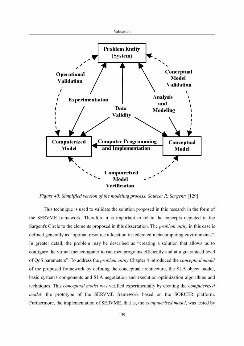
Validation
This technique is used to validate the solution proposed in this research in the form of
the SERVME framework. Therefore it is important to relate the concepts depicted in the
Sargent's Circle to the elements proposed in this dissertation. The problem entity in this case is
defined generally as “optimal resource allocation in federated metacomputing environments”.
In greater detail, the problem may be described as “creating a solution that allows us to
configure the virtual metacomputer to run metaprograms efficiently and at a guaranteed level
of QoS parameters”. To address the problem entity Chapter 4 introduced the conceptual model
of the proposed framework by defining the conceptual architecture, the SLA object model,
basic system's components and SLA negotiation and execution optimization algorithms and
techniques. This conceptual model was verified experimentally by creating the computerized
model: the prototype of the SERVME framework based on the SORCER platform.
Furthermore, the implementation of SERVME, that is, the computerized model, was tested by
139
Figure 40: Simplified version of the modeling process. Source: R. Sargent: [129]
Validation
applying it to solve a real world problem found in biology and bioengineering.
Sargent defines two types of validities: conceptual validity and operational validity.
According to [131] Conceptual model validity is defined as “...determining that the theories
and assumptions underlying the conceptual model are correct and that the model
representation of the problem entity is “reasonable” for the intended purpose of the model”
whereas Operational validity is defined as “...determining that the model’s output behavior
has sufficient accuracy for the model’s intended purpose over the domain of the model’s
intended applicability” [132].
The third aspect: verification, refers to the relation between the conceptual model and
the computerized model, that is, it allows for determining whether the computerized model
accurately represents the conceptual one.
As seen in Figure 40 conceptual model validity should be proved by examining the
conceptual model of the proposed solution. This task is carried out below in Section 5.2 where
the SERVME framework's class model and its technical architecture are presented.
Operational validity must be performed on the computerized model, that is, the implemented
prototype since it relates to issues that are difficult to prove theoretically such as: reliability,
scalability and performance, for example.
5.2. Conceptual validation
The conceptual model of the proposed solution is derived from the conceptual architecture,
the definition of components and their interactions. As a result, one of the ways to prove that
the conceptual model is valid, is by showing the validity of the architecture. This task is
accomplished in two steps. At first the SERVME reference implementation is analyzed from
the point of view of its class and packages model and secondly the technical architecture is
discussed.
5.2.1. SERVME model of packages and classes
Resource management is an integral part of any operating system. Similarly to single
computer platforms the metaoperating system such as the SORCER environment needs to
integrate the resource management elements deep in its architecture. Although it is possible to
140
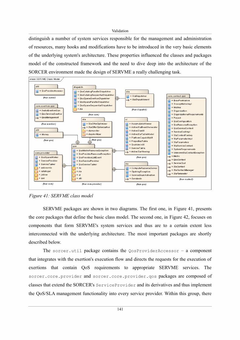
Validation
distinguish a number of system services responsible for the management and administration
of resources, many hooks and modifications have to be introduced in the very basic elements
of the underlying system's architecture. These properties influenced the classes and packages
model of the constructed framework and the need to dive deep into the architecture of the
SORCER environment made the design of SERVME a really challenging task.
SERVME packages are shown in two diagrams. The first one, in Figure 41, presents
the core packages that define the basic class model. The second one, in Figure 42, focuses on
components that form SERVME's system services and thus are to a certain extent less
interconnected with the underlying architecture. The most important packages are shortly
described below.
The sorcer.util package contains the QosProviderAccessor – a component
that integrates with the exertion's execution flow and directs the requests for the execution of
exertions that contain QoS requirements to appropriate SERVME services. The
sorcer.core.provider and sorcer.core.provider.qos packages are composed of
classes that extend the SORCER's ServiceProvider and its derivatives and thus implement
the QoS/SLA management functionality into every service provider. Within this group, there
141
Figure 41: SERVME class model
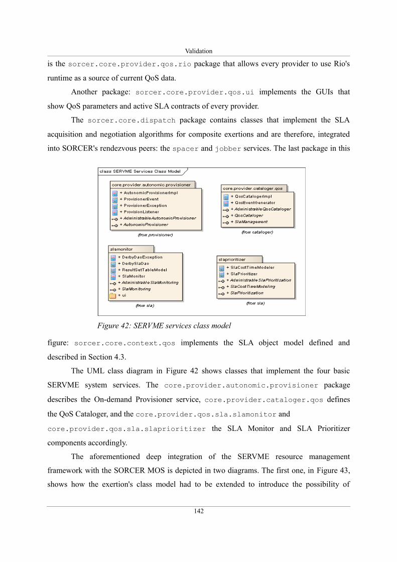
Validation
is the sorcer.core.provider.qos.rio package that allows every provider to use Rio's
runtime as a source of current QoS data.
Another package: sorcer.core.provider.qos.ui implements the GUIs that
show QoS parameters and active SLA contracts of every provider.
The sorcer.core.dispatch package contains classes that implement the SLA
acquisition and negotiation algorithms for composite exertions and are therefore, integrated
into SORCER's rendezvous peers: the spacer and jobber services. The last package in this
figure: sorcer.core.context.qos implements the SLA object model defined and
described in Section 4.3.
The UML class diagram in Figure 42 shows classes that implement the four basic
SERVME system services. The core.provider.autonomic.provisioner package
describes the On-demand Provisioner service, core.provider.cataloger.qos defines
the QoS Cataloger, and the core.provider.qos.sla.slamonitor and
core.provider.qos.sla.slaprioritizer the SLA Monitor and SLA Prioritizer
components accordingly.
The aforementioned deep integration of the SERVME resource management
framework with the SORCER MOS is depicted in two diagrams. The first one, in Figure 43,
shows how the exertion's class model had to be extended to introduce the possibility of
142
Figure 42: SERVME services class model
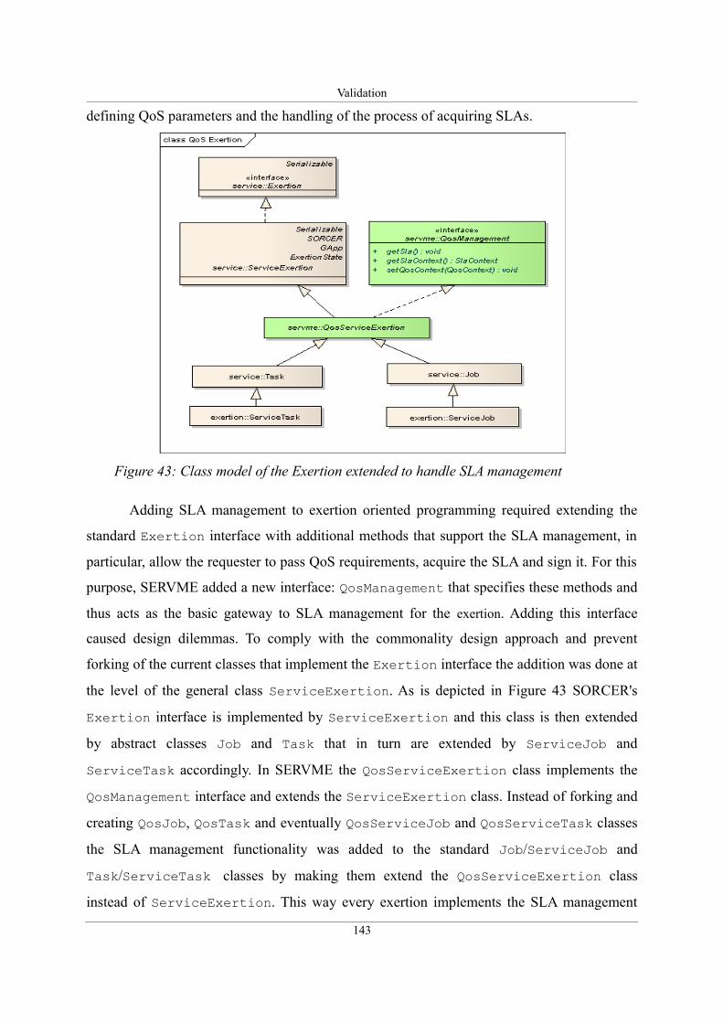
Validation
defining QoS parameters and the handling of the process of acquiring SLAs.
Adding SLA management to exertion oriented programming required extending the
standard Exertion interface with additional methods that support the SLA management, in
particular, allow the requester to pass QoS requirements, acquire the SLA and sign it. For this
purpose, SERVME added a new interface: QosManagement that specifies these methods and
thus acts as the basic gateway to SLA management for the exertion. Adding this interface
caused design dilemmas. To comply with the commonality design approach and prevent
forking of the current classes that implement the Exertion interface the addition was done at
the level of the general class ServiceExertion. As is depicted in Figure 43 SORCER's
Exertion interface is implemented by ServiceExertion and this class is then extended
by abstract classes Job and Task that in turn are extended by ServiceJob and
ServiceTask accordingly. In SERVME the QosServiceExertion class implements the
QosManagement interface and extends the ServiceExertion class. Instead of forking and
creating QosJob, QosTask and eventually QosServiceJob and QosServiceTask classes
the SLA management functionality was added to the standard Job/ServiceJob and
Task/ServiceTask classes by making them extend the QosServiceExertion class
instead of ServiceExertion. This way every exertion implements the SLA management
143
Figure 43: Class model of the Exertion extended to handle SLA management
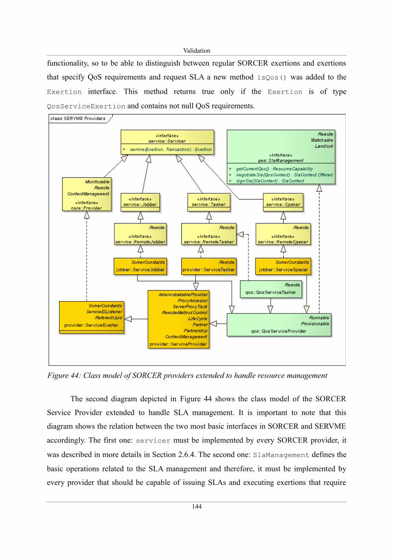
Validation
functionality, so to be able to distinguish between regular SORCER exertions and exertions
that specify QoS requirements and request SLA a new method isQos() was added to the
Exertion interface. This method returns true only if the Exertion is of type
QosServiceExertion and contains not null QoS requirements.
The second diagram depicted in Figure 44 shows the class model of the SORCER
Service Provider extended to handle SLA management. It is important to note that this
diagram shows the relation between the two most basic interfaces in SORCER and SERVME
accordingly. The first one: servicer must be implemented by every SORCER provider, it
was described in more details in Section 2.6.4. The second one: SlaManagement defines the
basic operations related to the SLA management and therefore, it must be implemented by
every provider that should be capable of issuing SLAs and executing exertions that require
144
Figure 44: Class model of SORCER providers extended to handle resource management
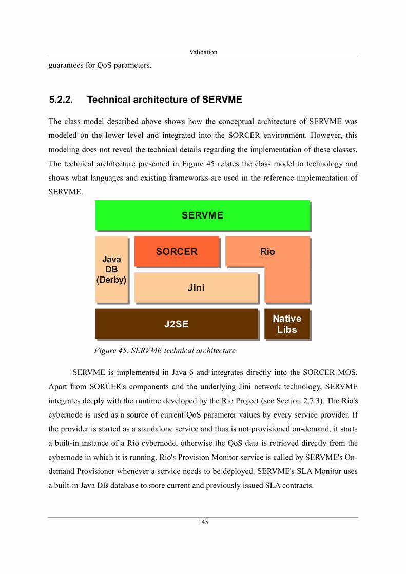
Validation
guarantees for QoS parameters.
5.2.2. Technical architecture of SERVME
The class model described above shows how the conceptual architecture of SERVME was
modeled on the lower level and integrated into the SORCER environment. However, this
modeling does not reveal the technical details regarding the implementation of these classes.
The technical architecture presented in Figure 45 relates the class model to technology and
shows what languages and existing frameworks are used in the reference implementation of
SERVME.
SERVME is implemented in Java 6 and integrates directly into the SORCER MOS.
Apart from SORCER's components and the underlying Jini network technology, SERVME
integrates deeply with the runtime developed by the Rio Project (see Section 2.7.3). The Rio's
cybernode is used as a source of current QoS parameter values by every service provider. If
the provider is started as a standalone service and thus is not provisioned on-demand, it starts
a built-in instance of a Rio cybernode, otherwise the QoS data is retrieved directly from the
cybernode in which it is running. Rio's Provision Monitor service is called by SERVME's On-
demand Provisioner whenever a service needs to be deployed. SERVME's SLA Monitor uses
a built-in Java DB database to store current and previously issued SLA contracts.
145
Figure 45: SERVME technical architecture
J2SEJ2SE NativeLibs
NativeLibs
JiniJini
RioRioSORCERSORCERJavaDB
(Derby)
JavaDB
(Derby)
SERVMESERVME
Validation
5.3. Operational validation: introducing a real world
use case scenario
The goal of the operational validation is to determine whether the proposed computerized
model behaves accurately when applied to solve the original research problem in a setting
defined in the requirements. This part of the validation is particularly important when it comes
to distributed computing. The inherent complexity of these kinds of systems often renders the
theoretical and conceptual models useless and therefore, the conceptual architecture must be
extensively tested, for example, on solving computational problems taken from the real world.
Such an example of a magnetic resonance imaging (MRI) processing was proposed during the
requirements analysis stage in Section 3.4. However, for practical reasons – the author's return
from the USA to Poland – the final tests had to be run on a different example and in a
different deployment setting.
5.3.1. Protein sequencing using Rosetta
The problem addressed in the use case scenario for the final tests of the proposed resource
management framework focuses on protein sequencing. According to Wikipedia [133]:
“Discovering the structures and functions of proteins in living organisms is an important tool
for understanding cellular processes, and allows drugs that target specific metabolic pathways
to be invented more easily.” There is a number of algorithms and tools developed to compute
the amino acid sequences of its constituent peptides. However, as Rohl et al. claim “Double-
blind assessments of protein structure prediction methods, held biannually in the community-
wide critical assessment of structure prediction (CASP) experiments, have documented
significant progress in the field of protein structure prediction and have indicated that the
Rosetta algorithm is perhaps the most successful current method for de novo protein structure
prediction.” [134].
Rosetta is widely adopted and has become a de facto standard for scientists involved
with protein sequencing. Its popularity may be proved by the fact that it was ported to the
Berkeley Open Infrastructure for Network Computing (BOINC) [135] and as Rosetta@home
[136] is available for anyone who wants to contribute to science by devoting part of their CPU
time. Unfortunately, not all scientists can benefit from free CPU time that comes from
146
Validation
volunteers. Despite the availability of this distributed version of this software, many
researchers still struggle to find computing resources and manage them in an efficient way.
This applies, for example, to a group of scientists from the International Institute of Molecular
and Cell Biology located in Warsaw, Poland [137]. The presented use case scenario was
designed to help those researchers manage their computing resources and tasks in an efficient
way by deploying the SERVME environment.
The goal behind protein structure prediction is to develop methods and algorithms that
will allow us to predict and order any given protein structures of any length of the amino acid
chain. The way scientists are trying to achieve this is by generating computed models of
proteins, so called decoys, and comparing them with the real structure solved by experimental
methods.
The use case scenario involved running multiple simultaneous computations to
generate a large number of decoys for a particular protein structure. For practical reasons,
since it is easier to observe how well the SERVME framework manages resources on a small
example, the chosen structure is rather short. This protein known as the 2KHT structure has a
length of 30 residues and is represented by the following sequence:
ACYCRIPACIAGERRYGTCIYQGRLWAFCC
The computations were run using the standalone Rosetta software in version 3.1.
5.3.2. Deployment used during the validation
Distributed computing involves running computations on a large number of computers. An
appropriate setting is difficult to find since to ensure the comparability of different tests the
resource usage of the platform should be kept at the same level throughout the whole duration
of the experiment. In practice, this implies that the whole platform should be available for the
exclusive usage of the researcher.
During the development of the reference implementation of the proposed framework
the author was given access to a deployment that was truly heterogeneous with respect to both
hardware and software. This setting was similar to the one depicted in the requirements
analysis in Figure 14 on page 76. Unfortunately, this platform was not available for the final
validation, however, a different setting could be used. This platform is presented in the
deployment diagram in Figure 46.
147
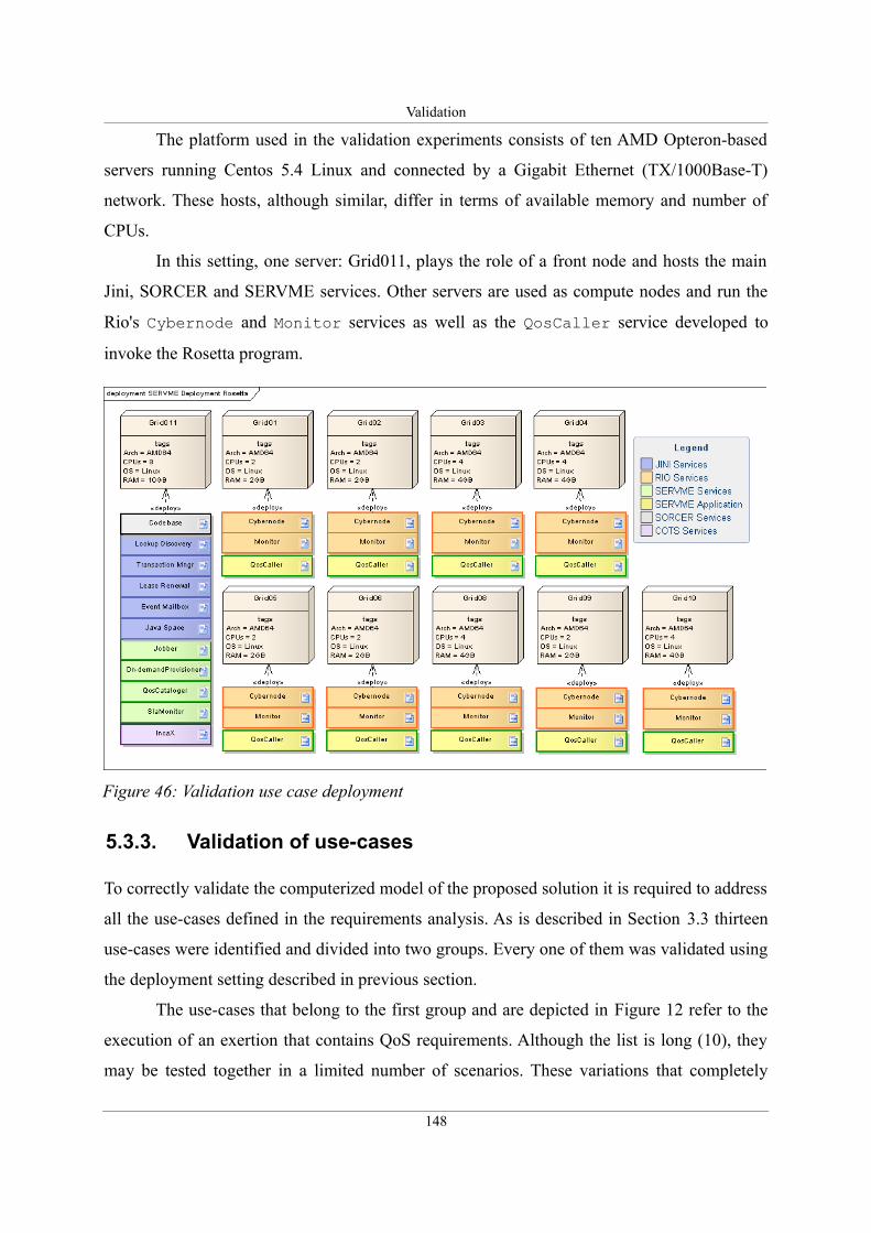
Validation
The platform used in the validation experiments consists of ten AMD Opteron-based
servers running Centos 5.4 Linux and connected by a Gigabit Ethernet (TX/1000Base-T)
network. These hosts, although similar, differ in terms of available memory and number of
CPUs.
In this setting, one server: Grid011, plays the role of a front node and hosts the main
Jini, SORCER and SERVME services. Other servers are used as compute nodes and run the
Rio's Cybernode and Monitor services as well as the QosCaller service developed to
invoke the Rosetta program.
5.3.3. Validation of use-cases
To correctly validate the computerized model of the proposed solution it is required to address
all the use-cases defined in the requirements analysis. As is described in Section 3.3 thirteen
use-cases were identified and divided into two groups. Every one of them was validated using
the deployment setting described in previous section.
The use-cases that belong to the first group and are depicted in Figure 12 refer to the
execution of an exertion that contains QoS requirements. Although the list is long (10), they
may be tested together in a limited number of scenarios. These variations that completely
148
Figure 46: Validation use case deployment
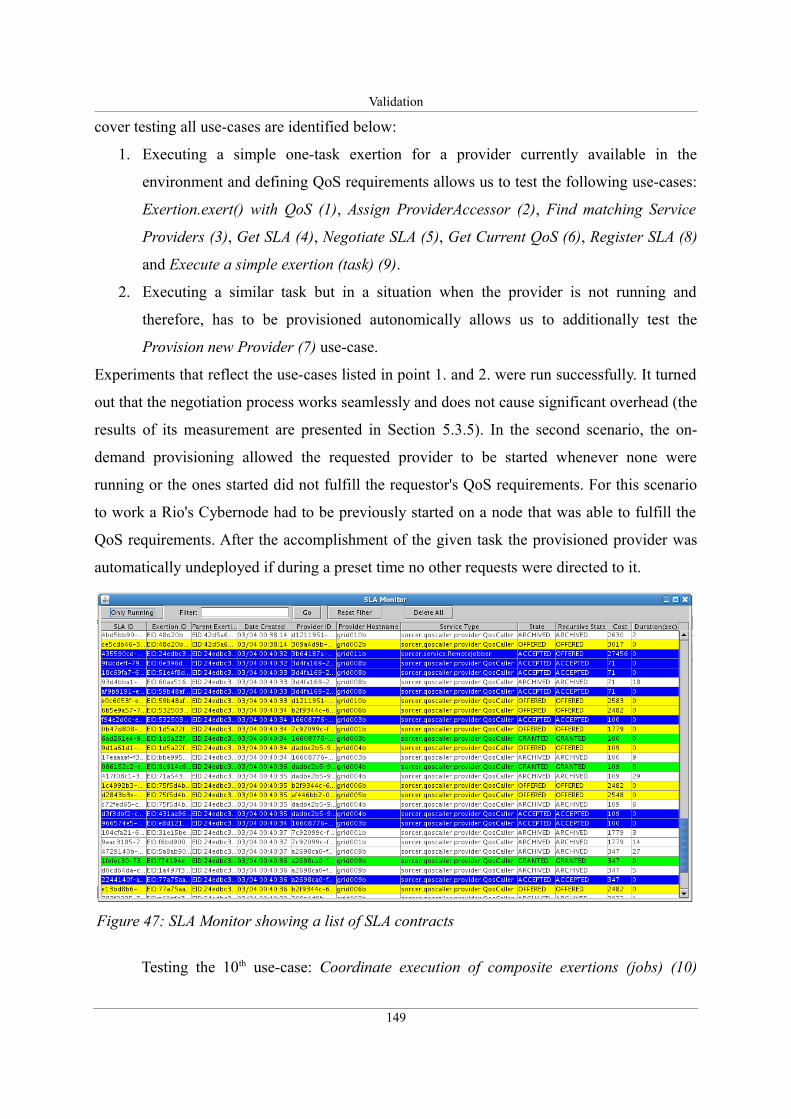
Validation
cover testing all use-cases are identified below:
1. Executing a simple one-task exertion for a provider currently available in the
environment and defining QoS requirements allows us to test the following use-cases:
Exertion.exert() with QoS (1), Assign ProviderAccessor (2), Find matching Service
Providers (3), Get SLA (4), Negotiate SLA (5), Get Current QoS (6), Register SLA (8)
and Execute a simple exertion (task) (9).
2. Executing a similar task but in a situation when the provider is not running and
therefore, has to be provisioned autonomically allows us to additionally test the
Provision new Provider (7) use-case.
Experiments that reflect the use-cases listed in point 1. and 2. were run successfully. It turned
out that the negotiation process works seamlessly and does not cause significant overhead (the
results of its measurement are presented in Section 5.3.5). In the second scenario, the on-
demand provisioning allowed the requested provider to be started whenever none were
running or the ones started did not fulfill the requestor's QoS requirements. For this scenario
to work a Rio's Cybernode had to be previously started on a node that was able to fulfill the
QoS requirements. After the accomplishment of the given task the provisioned provider was
automatically undeployed if during a preset time no other requests were directed to it.
Testing the 10th use-case: Coordinate execution of composite exertions (jobs) (10)
149
Figure 47: SLA Monitor showing a list of SLA contracts
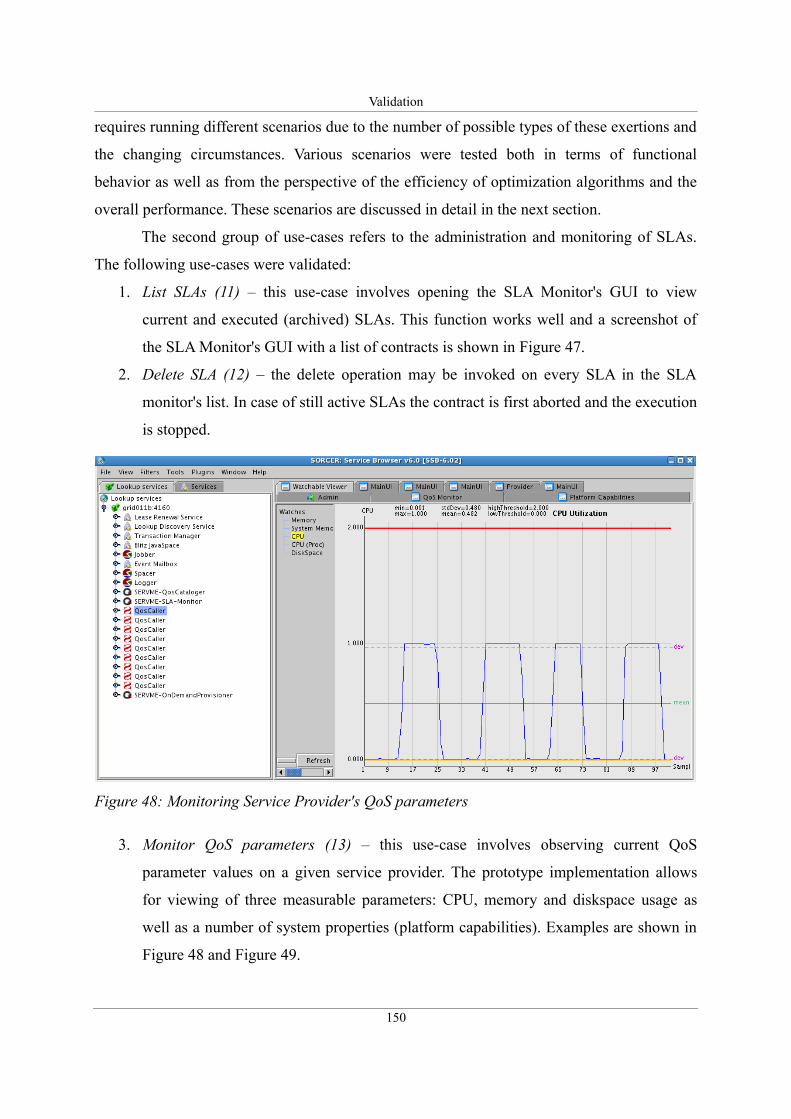
Validation
requires running different scenarios due to the number of possible types of these exertions and
the changing circumstances. Various scenarios were tested both in terms of functional
behavior as well as from the perspective of the efficiency of optimization algorithms and the
overall performance. These scenarios are discussed in detail in the next section.
The second group of use-cases refers to the administration and monitoring of SLAs.
The following use-cases were validated:
1. List SLAs (11) – this use-case involves opening the SLA Monitor's GUI to view
current and executed (archived) SLAs. This function works well and a screenshot of
the SLA Monitor's GUI with a list of contracts is shown in Figure 47.
2. Delete SLA (12) – the delete operation may be invoked on every SLA in the SLA
monitor's list. In case of still active SLAs the contract is first aborted and the execution
is stopped.
3. Monitor QoS parameters (13) – this use-case involves observing current QoS
parameter values on a given service provider. The prototype implementation allows
for viewing of three measurable parameters: CPU, memory and diskspace usage as
well as a number of system properties (platform capabilities). Examples are shown in
Figure 48 and Figure 49.
150
Figure 48: Monitoring Service Provider's QoS parameters
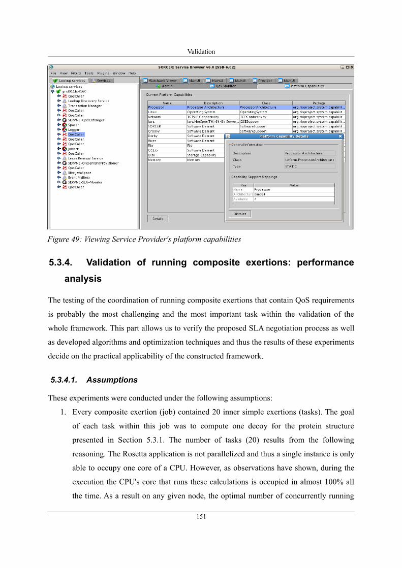
Validation
5.3.4. Validation of running composite exertions: performance
analysis
The testing of the coordination of running composite exertions that contain QoS requirements
is probably the most challenging and the most important task within the validation of the
whole framework. This part allows us to verify the proposed SLA negotiation process as well
as developed algorithms and optimization techniques and thus the results of these experiments
decide on the practical applicability of the constructed framework.
5.3.4.1. Assumptions
These experiments were conducted under the following assumptions:
1. Every composite exertion (job) contained 20 inner simple exertions (tasks). The goal
of each task within this job was to compute one decoy for the protein structure
presented in Section 5.3.1. The number of tasks (20) results from the following
reasoning. The Rosetta application is not parallelized and thus a single instance is only
able to occupy one core of a CPU. However, as observations have shown, during the
execution the CPU's core that runs these calculations is occupied in almost 100% all
the time. As a result on any given node, the optimal number of concurrently running
151
Figure 49: Viewing Service Provider's platform capabilities
Validation
Rosetta processes should be at most equal to the total number of CPU cores. Since the
total number of cores of all compute nodes used in the experiment amounts to 26, the
chosen number of tasks (20) allows the job to be, at least theoretically, computed
simultaneously at once on the whole cluster. This property is a requirement if Push
type of jobs are to be run (see Section 4.5.6 for a detailed explanation). In fact, this
limit was tested and as predicted for any job larger than 26 tasks (the same as the total
number of cores) the exertion failed due to the lack of available resources.
2. As may be implied from the previous point, the QoS requirements for each task
requested an exclusive reservation of one CPU's core to the given task.
3. Te ensure comparability of results during the experiments the cluster was not used by
any other user and no other jobs were run simultaneously.
4. Every provider used a cost/time approximation model in which the cost is inversely
proportional to the execution time – as a result the execution on faster machines is
more costly than on lower-end hardware. In these tests the chosen algorithm was
rather simple. The cost was estimated according to the following formula:
EstimatedCost=5000
EstimatedTime, where the EstimatedTime expressed in milliseconds
was calculated as the average execution time for previously run exertions with similar
parameters: in this case, since the tasks were practically identical, this applied to
calculations of all previous decoys. In case of the first round of calculations on a given
provider, when no historical data was present, the EstimatedTime was arbitrarily set to
70 seconds. This input value was calculated before the actual experiment as the
average execution time for a single decoy calculation on a large number of tasks.
5. The cost of coordinating a job using any rendezvous peer was constant and set to 100
units.
6. The initial parameter (EstimatedTime) used by service providers to estimate execution
costs and time were identical for all providers and for every type of tested jobs. In fact,
the data regarding historical executions was erased after every series of tests.
7. On-demand provisioning was not addressed in these experiments and thus all
providers were manually started or restarted before every series of tests.
8. For better accuracy and to avoid a discussion about the distribution of the observed
execution times and costs all experiments were repeated many times. (50 for jobs with
152
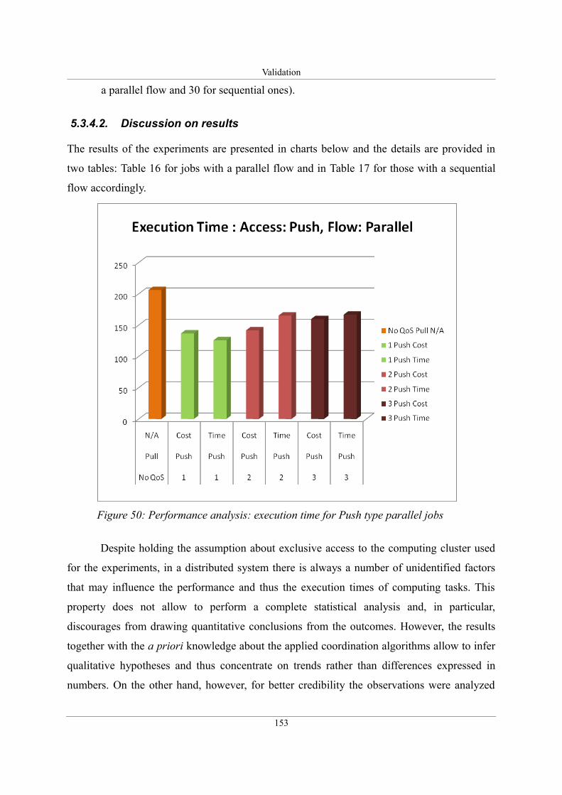
Validation
a parallel flow and 30 for sequential ones).
5.3.4.2. Discussion on results
The results of the experiments are presented in charts below and the details are provided in
two tables: Table 16 for jobs with a parallel flow and in Table 17 for those with a sequential
flow accordingly.
Despite holding the assumption about exclusive access to the computing cluster used
for the experiments, in a distributed system there is always a number of unidentified factors
that may influence the performance and thus the execution times of computing tasks. This
property does not allow to perform a complete statistical analysis and, in particular,
discourages from drawing quantitative conclusions from the outcomes. However, the results
together with the a priori knowledge about the applied coordination algorithms allow to infer
qualitative hypotheses and thus concentrate on trends rather than differences expressed in
numbers. On the other hand, however, for better credibility the observations were analyzed
153
Figure 50: Performance analysis: execution time for Push type parallel jobs
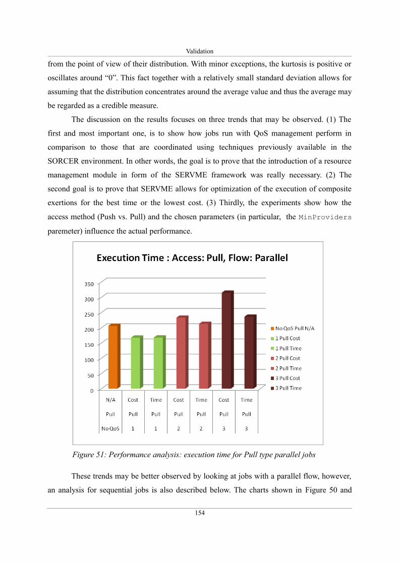
Validation
from the point of view of their distribution. With minor exceptions, the kurtosis is positive or
oscillates around “0”. This fact together with a relatively small standard deviation allows for
assuming that the distribution concentrates around the average value and thus the average may
be regarded as a credible measure.
The discussion on the results focuses on three trends that may be observed. (1) The
first and most important one, is to show how jobs run with QoS management perform in
comparison to those that are coordinated using techniques previously available in the
SORCER environment. In other words, the goal is to prove that the introduction of a resource
management module in form of the SERVME framework was really necessary. (2) The
second goal is to prove that SERVME allows for optimization of the execution of composite
exertions for the best time or the lowest cost. (3) Thirdly, the experiments show how the
access method (Push vs. Pull) and the chosen parameters (in particular, the MinProviders
paremeter) influence the actual performance.
These trends may be better observed by looking at jobs with a parallel flow, however,
an analysis for sequential jobs is also described below. The charts shown in Figure 50 and
154
Figure 51: Performance analysis: execution time for Pull type parallel jobs
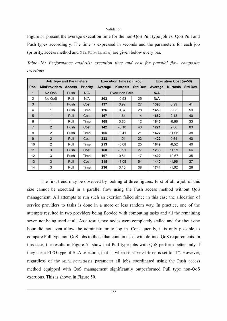
Validation
Figure 51 present the average execution time for the non-QoS Pull type job vs. QoS Pull and
Push types accordingly. The time is expressed in seconds and the parameters for each job
(priority, access method and MinProviders) are given below every bar.
Table 16: Performance analysis: execution time and cost for parallel flow composite
exertions
Job Type and Parameters Execution Time (s) (n=50) Execution Cost (n=50)
Pos. MinProviders Access Priority Average Kurtosis Std Dev. Average Kurtosis Std Dev.
1 No QoS Push N/A Execution Fails N/A
2 No QoS Pull N/A 203 -0.53 25 N/A
3 1 Push Cost 137 0,92 27 1398 0,99 41
4 1 Push Time 126 0,37 28 1459 8,05 59
5 1 Pull Cost 167 1,64 14 1682 2,13 40
6 1 Pull Time 168 0,60 12 1645 -0,66 33
7 2 Push Cost 142 -0,10 40 1221 2,06 83
8 2 Push Time 165 -0,41 21 1427 31,05 38
9 2 Pull Cost 233 1,01 23 1422 0,64 40
10 2 Pull Time 213 -0,68 25 1649 -0,52 40
11 3 Push Cost 160 -0,91 27 1233 11,29 66
12 3 Push Time 167 0,81 17 1402 19,67 35
13 3 Pull Cost 315 -1,08 54 1440 -1,96 37
14 3 Pull Time 236 0,15 38 1744 -1,02 26
The first trend may be observed by looking at three figures. First of all, a job of this
size cannot be executed in a parallel flow using the Push access method without QoS
management. All attempts to run such an exertion failed since in this case the allocation of
service providers to tasks is done in a more or less random way. In practice, one of the
attempts resulted in two providers being flooded with computing tasks and all the remaining
seven not being used at all. As a result, two nodes were completely stalled and for about one
hour did not even allow the administrator to log in. Consequently, it is only possible to
compare Pull type non-QoS jobs to those that contain tasks with defined QoS requirements. In
this case, the results in Figure 51 show that Pull type jobs with QoS perform better only if
they use a FIFO type of SLA selection, that is, when MinProviders is set to “1”. However,
regardless of the MinProviders parameter all jobs coordinated using the Push access
method equipped with QoS management significantly outperformed Pull type non-QoS
exertions. This is shown in Figure 50.
155
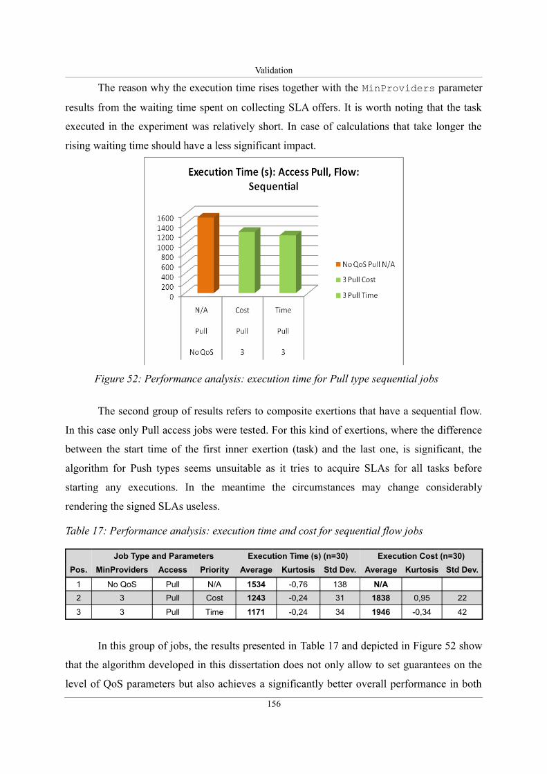
Validation
The reason why the execution time rises together with the MinProviders parameter
results from the waiting time spent on collecting SLA offers. It is worth noting that the task
executed in the experiment was relatively short. In case of calculations that take longer the
rising waiting time should have a less significant impact.
The second group of results refers to composite exertions that have a sequential flow.
In this case only Pull access jobs were tested. For this kind of exertions, where the difference
between the start time of the first inner exertion (task) and the last one, is significant, the
algorithm for Push types seems unsuitable as it tries to acquire SLAs for all tasks before
starting any executions. In the meantime the circumstances may change considerably
rendering the signed SLAs useless.
Table 17: Performance analysis: execution time and cost for sequential flow jobs
Job Type and Parameters Execution Time (s) (n=30) Execution Cost (n=30)
Pos. MinProviders Access Priority Average Kurtosis Std Dev. Average Kurtosis Std Dev.
1 No QoS Pull N/A 1534 -0,76 138 N/A
2 3 Pull Cost 1243 -0,24 31 1838 0,95 22
3 3 Pull Time 1171 -0,24 34 1946 -0,34 42
In this group of jobs, the results presented in Table 17 and depicted in Figure 52 show
that the algorithm developed in this dissertation does not only allow to set guarantees on the
level of QoS parameters but also achieves a significantly better overall performance in both
156
Figure 52: Performance analysis: execution time for Pull type sequential jobs
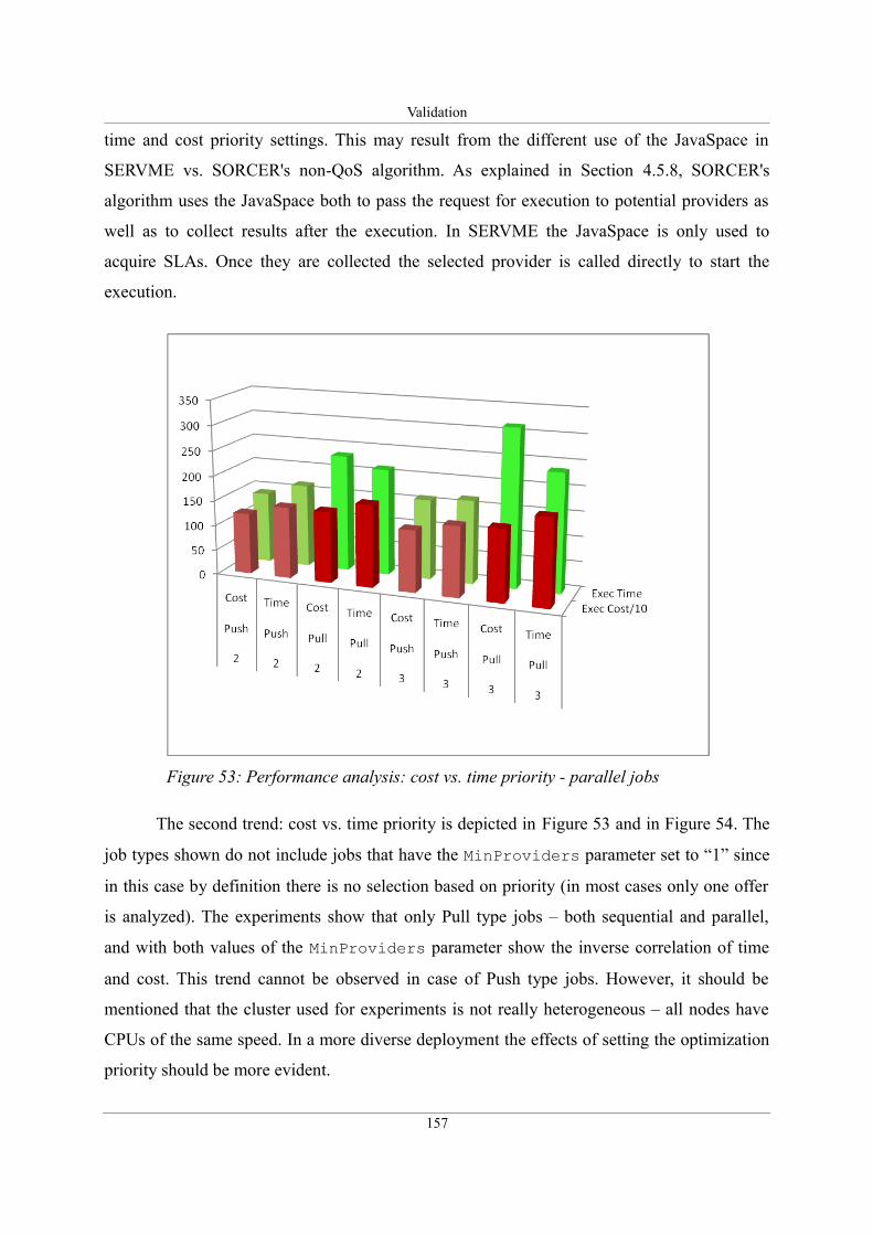
Validation
time and cost priority settings. This may result from the different use of the JavaSpace in
SERVME vs. SORCER's non-QoS algorithm. As explained in Section 4.5.8, SORCER's
algorithm uses the JavaSpace both to pass the request for execution to potential providers as
well as to collect results after the execution. In SERVME the JavaSpace is only used to
acquire SLAs. Once they are collected the selected provider is called directly to start the
execution.
The second trend: cost vs. time priority is depicted in Figure 53 and in Figure 54. The
job types shown do not include jobs that have the MinProviders parameter set to “1” since
in this case by definition there is no selection based on priority (in most cases only one offer
is analyzed). The experiments show that only Pull type jobs – both sequential and parallel,
and with both values of the MinProviders parameter show the inverse correlation of time
and cost. This trend cannot be observed in case of Push type jobs. However, it should be
mentioned that the cluster used for experiments is not really heterogeneous – all nodes have
CPUs of the same speed. In a more diverse deployment the effects of setting the optimization
priority should be more evident.
157
Figure 53: Performance analysis: cost vs. time priority - parallel jobs
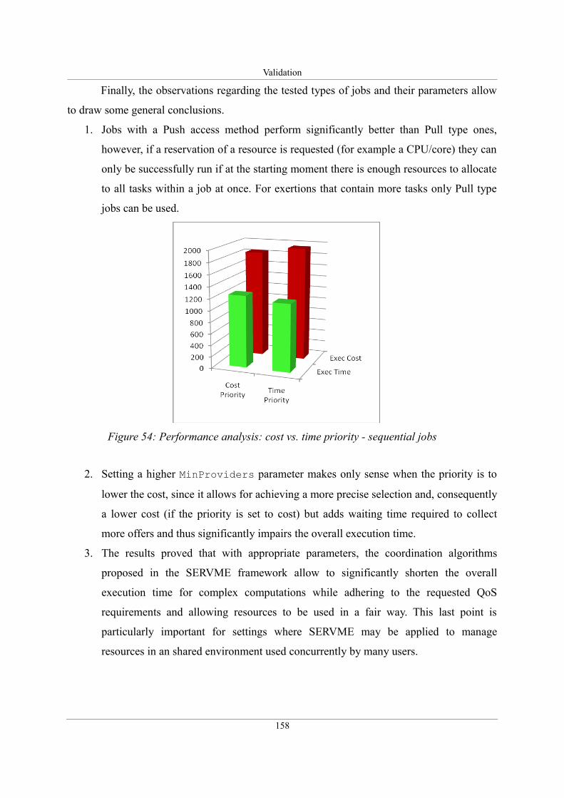
Validation
Finally, the observations regarding the tested types of jobs and their parameters allow
to draw some general conclusions.
1. Jobs with a Push access method perform significantly better than Pull type ones,
however, if a reservation of a resource is requested (for example a CPU/core) they can
only be successfully run if at the starting moment there is enough resources to allocate
to all tasks within a job at once. For exertions that contain more tasks only Pull type
jobs can be used.
2. Setting a higher MinProviders parameter makes only sense when the priority is to
lower the cost, since it allows for achieving a more precise selection and, consequently
a lower cost (if the priority is set to cost) but adds waiting time required to collect
more offers and thus significantly impairs the overall execution time.
3. The results proved that with appropriate parameters, the coordination algorithms
proposed in the SERVME framework allow to significantly shorten the overall
execution time for complex computations while adhering to the requested QoS
requirements and allowing resources to be used in a fair way. This last point is
particularly important for settings where SERVME may be applied to manage
resources in an shared environment used concurrently by many users.
158
Figure 54: Performance analysis: cost vs. time priority - sequential jobs
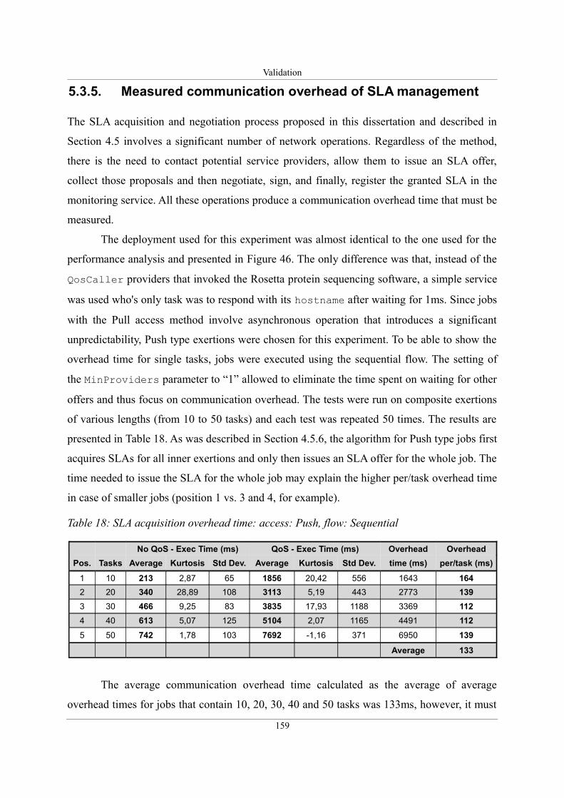
Validation
5.3.5. Measured communication overhead of SLA management
The SLA acquisition and negotiation process proposed in this dissertation and described in
Section 4.5 involves a significant number of network operations. Regardless of the method,
there is the need to contact potential service providers, allow them to issue an SLA offer,
collect those proposals and then negotiate, sign, and finally, register the granted SLA in the
monitoring service. All these operations produce a communication overhead time that must be
measured.
The deployment used for this experiment was almost identical to the one used for the
performance analysis and presented in Figure 46. The only difference was that, instead of the
QosCaller providers that invoked the Rosetta protein sequencing software, a simple service
was used who's only task was to respond with its hostname after waiting for 1ms. Since jobs
with the Pull access method involve asynchronous operation that introduces a significant
unpredictability, Push type exertions were chosen for this experiment. To be able to show the
overhead time for single tasks, jobs were executed using the sequential flow. The setting of
the MinProviders parameter to “1” allowed to eliminate the time spent on waiting for other
offers and thus focus on communication overhead. The tests were run on composite exertions
of various lengths (from 10 to 50 tasks) and each test was repeated 50 times. The results are
presented in Table 18. As was described in Section 4.5.6, the algorithm for Push type jobs first
acquires SLAs for all inner exertions and only then issues an SLA offer for the whole job. The
time needed to issue the SLA for the whole job may explain the higher per/task overhead time
in case of smaller jobs (position 1 vs. 3 and 4, for example).
Table 18: SLA acquisition overhead time: access: Push, flow: Sequential
No QoS - Exec Time (ms) QoS - Exec Time (ms) Overhead Overhead
Pos. Tasks Average Kurtosis Std Dev. Average Kurtosis Std Dev. time (ms) per/task (ms)
1 10 213 2,87 65 1856 20,42 556 1643 164
2 20 340 28,89 108 3113 5,19 443 2773 139
3 30 466 9,25 83 3835 17,93 1188 3369 112
4 40 613 5,07 125 5104 2,07 1165 4491 112
5 50 742 1,78 103 7692 -1,16 371 6950 139
Average 133
The average communication overhead time calculated as the average of average
overhead times for jobs that contain 10, 20, 30, 40 and 50 tasks was 133ms, however, it must
159
Validation
be noted that in a distributed system that involves so many elements as the SERVME
framework even potentially insignificant factors may strongly influence the results. As a
result, the exact numbers should be treated with caution. However, the importance of this
experiment results from the fact that even in comparison with relatively short computational
tasks, such as the protein sequencing example described in Section 5.3.1, the communication
overhead time spent on the negotiation and management of SLAs is insignificant.
5.4. Summary
This chapter presented the validation of the proposed resource management framework. The
discussion of validation and verification methods presented in Section 5.1 motivated and
described in detail the approach that was followed later. This method focused first on
conceptual validation that was presented in Section 5.2 and included the description of the
model of classes and packages as well as the technical architecture. The second part of the
validation, shown in Section 5.3, concentrated on operational validity. This part included the
discussion of use-cases introduced in the requirements analysis in Chapter 3 as well as a
detailed performance analysis of the proposed framework that was conducted on a
computationally intensive use-case scenario that involved protein structure prediction. The
last part of this chapter focused on the measured communication overhead time spent on SLA
negotiation and management.
The outcomes presented in this chapter demonstrate that the proposed model of a
resource management module of the metaoperating system is valid and accurately addresses
the research problem defined in the introduction. This is motivated by the observed relatively
small overhead time and the results of the performance analysis, that show that the
introduction of the SERVME framework allows for significant shortening of the overall
execution time of composite exertions while preserving a guaranteed level of service.
160
Conclusions and Future Work
Chapter 6. Conclusions and Future Work
All truths are easy to understand once they are discovered; the point is to discover them.
Galileo Galilei
As shown in this dissertation it is possible to build a computing system that allows for
optimal management of the available resources. It is also possible to configure the processor
of the virtual metacomputer to execute metaprograms and allocate resources using Service
Level Agreements to guarantee the requested Quality of Service parameters. The result of this
work is the successful validation of the proposed solution for resource management in
federated metacomputing. The solution is regarded as a module of an operating system
permitting the management of computing resources of the virtual metacomputer. The
investigated resource management model advances the understanding, the theory and the
practice of metaoperating systems by proposing a verifiable optimal resource management
framework and its new and original dynamic federated architecture.
To the best of my knowledge, this is the first work that addresses the problem of
resource management of metacomputing platforms built using the Service Object-Oriented
Architecture, where service providers federate dynamically to form on-the-fly collaborations
to execute metaprograms and dissolve upon finishing the execution. This work complements
the previous research on the SORCER project and allows it to become a fully functional
metaoperating system.
This dissertation has contributed to the theory and practice of distributed computing
by proposing the following:
1. The definition of the QoS/SLA model that allows us to describe and match QoS
requirements to capabilities of resources.
2. The design of the conceptual and component architecture of the proposed SERVME
161
Conclusions and Future Work
framework that includes the definition of communication interfaces presented in detail
in Appendix A and the definition of the SERVME system services such as:
QosCataloger, SlaMonitor, SlaPrioritizer and OnDemandProvisioner.
3. The development of SLA negotiation algorithms for simple and composite exertions.
These algorithms address the jobs that use a simple Push access method of
coordination as well as those that use the space-based computing approach to
asynchronously manage the execution of large exertions.
4. The development of multiobjective job optimization techniques that may be applied to
optimize the execution of composite exertions for the shortest time at a constrained
cost or the opposite, that is, the lowest cost but at a limited maximum execution time.
The benefits resulting from the introduction of resource management to federated
metacomputing include:
• Better resource allocation, what allows us to achieve the best performance or the
lowest cost of requestor's inquiries: time/cost optimization.
• Flexibility in assigning QoS to requestor's inquires and provisioned services.
• Accounting for flexible resource utilization based on dynamic cost metrics.
• Efficient QoS-based metaprogramming: matching available service providers or using
on-demand service provisioning to deploy them when needed.
• Flexible and extensible negotiation and management of leased SLA agreements for
related QoS parameters.
• User friendly and zero-install GUIs for configuration, monitoring, and administration
of SERVME infrastructure services.
• SLA prioritization that provides means to manage the prioritization of tasks according
to the organization’s strategy that defines "who is computing what and where".
• Better hardware utilization via on-demand provisioning and fair use of available
resources, based on free-market economy as a result of the introduction of SERVME's
allocation and coordination algorithms.
The proposed architecture was validated by implementing a prototype. The references
implementation was tested in a real world use-case scenario that involved computationally
intensive protein structure prediction calculations. The conducted performance analysis led to
the observation that, given the appropriate parameters, the proposed coordination algorithms
162
Conclusions and Future Work
allow us to significantly shorten the overall execution time of composite exertions while
preserving the guaranteed level of service.
6.1. Future work
As the experiments have shown, the proposed framework is ready to manage distributed
resources and help to better allocate them. However, there are still a number of issues that
have been identified as needing further enhancements. Those include:
• The implementation and validation of the SlaPrioritizer service.
• Extending the cost accounting functionality.
• The integration of multiobjective optimization algorithms into the reference
architecture; the validation of the integrated architecture in similar settings as the use-
case scenario and the deployment used in the experiments in Chapter 5.
• Development of execution optimization algorithms for composite exertions with a
multi-level inner hierarchy.
• Dynamic SLA execution monitoring and failure handling. Currently, SERVME allows
for acquiring an SLA contract and starting the execution on a selected provider.
However, the QoS parameters are not monitored throughout the execution. Autonomic
monitoring solutions should be proposed that enable the requestor to define policies
that react to events such as the breaching of a signed SLA contract.
• Service Runtime Migration (Hot Migration), which is one of the possible reactions to
an event such as the breaching of a signed SLA. The issue is to envision a solution that
is capable of transferring a service to a different host together with the current session
data allowing the execution to be continued on a different node.
163

Glossary
Chapter 7. Glossary
COTS – Commercial, off-the-shelf (COTS) or simply off the shelf (OTS) – these terms
refer to computer software or hardware, technology, or computer products that are ready-
made and available for sale, lease, or license to the general public [based on Wikipedia].
Measurable Capability – a current performance benchmark value of a varying characteristic
of a system resource. i.e. current CPU/Memory/Disk utilization, number of requests per
second served etc.
Metacomputer – according to the National Center for Supercomputing Applications
(NCSA): a collection of computers held together by state-of-the-art technology and
"balanced" so that, to the individual user, it looks and acts like a single computer. In the
SORCER environment the metacomputer or virtual metacomputer is regarded as the
collection of service providers that federate dynamically, on-the-fly to execute a
metaprogram.
Metaoperating System – also referred to as Metacompute Operating System – an
intermediary layer between the virtual metacomputer and metaprograms. A system designed
to enable the execution and coordination of metaprograms and manage resources in a
distributed environment. The SORCER environment extended by the proposed SERVME
framework is regarded as a metaoperating system.
Metaprograms – programs written in terms of other programs. The SORCER project defined
the metaprogram and called it exertion. The exertion extends the basic object model by adding
the control strategy as the third element besides data and operations. Details are presented in
Section 2.6.3.
Metric – a named, dynamic value calculated on the basis of QoS parameters (both Platform
165
Glossary
Capabilities and Measurable Capabilities) or other metrics (composite metric) specified by the
service requestor in the SLA.
Optimal Resource Allocation – most satisfactory resource allocation for a given program as
specified by its QoS and guaranteed by SLA of the underlying operating system. The details
regarding the understanding of the optimal resource allocation in this dissertation are
explained in Section 2.8.
Platform Capability – a fixed property which defines the capability offered by a system
resource. i.e. software libraries, software version, number of CPUs, CPU architecture etc.
[concept based on the Rio Project].
Provider Cost Model – a set of algorithms that specify how the cost of using a specific
Service Provider is calculated. It may consist of several resource cost models referring to
system resources used by the Service Provider.
Quality of Service (Qos) Parameter – a technical characteristic or performance benchmark
of a system resource. QoS Parameter can represent a platform capability as well as a
measurable capability. QoS Parameters can also be divided into two other groups: System
Capabilities and User-defined/Application-specific Capabilities.
Resource Cost Model – a set of algorithms that specify how the cost of using a specific
system resource is calculated. The evaluation very often takes into account time and QoS
parameters.
Service Level Agreement (SLA) – an agreement signed between a service requestor and a
service provider for a specific exertion, which defines all SLA Parameters for this exertion. A
breaching of one of those SLA Parameters results in the breaching of the whole SLA.
Service Provider – software component or application offering a functionality (service) to
service requestors. A Service Provider is aware of the capabilities (QoS Parameters) it can
offer to service requestors as well as has a predefined provider cost model.
Service Requestor – software component or application which is requesting the execution of
a certain type of a task/operation on a supplied data set and with a specific control strategy.
SERVME – SERViceable Metacomputing Environment – the resource management
166
Glossary
framework defined and proposed in this dissertation.
SLA Negotiation – a process of reaching a Service Level Agreement between a service
requestor and service providers.
SLA parameter – an agreement signed between a service requestor and a service provider for
a specific exertion, it specifies that during the execution time of this exertion a particular QoS
Parameter or Metric should:
• hold a specific value - in case of a platform capability, or
• be within a certain range defined by low and high threshold values - in case of a
measurable capability.
System Capabilities – widely known and generally applicable capabilities of system
resources both of fixed property type (platform capabilities) and performance benchmark type
(measurable capabilities).
System Resource – any physical or virtual (software) component of limited availability
within a computer system [based on Wikipedia].
User-defined/Application-specific Capabilities – mostly software-related capabilities
specified by the user or developer of a certain application (a service provider) i.e. number of
operations calculated by this application per second.
167

Bibliography
Chapter 8. Bibliography
[1] M. Sobolewski, “Exertion Oriented Programming,” International Journal on Computer
Science and Information Systems, pp. 86-109.
[2] M. Sobolewski, “SORCER: Computing and Metacomputing Intergrid,” 10th
International Conference on Enterprise Information Systems, Barcelona, Spain: 2008.
[3] M. Sobolewski, “Federated P2P services in CE environments,” Proceedings of
Concurrent Engineering CE2002, 2002.
[4] “Operating System - Definition from the Merriam-Webster Online Dictionary,”
http://www.merriam-webster.com/dictionary/Operating%20System, Oct. 2009.
[5] “What is operating system? - Definition from Whatis.com - see also: OS,”
http://searchcio-midmarket.techtarget.com/sDefinition/0,,sid183_gci212714,00.html,
Oct. 2009.
[6] A. Silberschatz, P.B. Galvin, and G. Gagne, Operating system concepts 5th Ed.,
Addison-Wesley, 1998.
[7] “Computing platform - Wikipedia, the free encyclopedia,”
http://en.wikipedia.org/wiki/Computing_platform, Oct. 2009.
[8] A.S. Tanenbaum, Modern operating systems, Prentice Hall, 2001.
[9] A.S. Tanenbaum and R.V. Renesse, “Distributed operating systems,” ACM Comput.
Surv., vol. 17, 1985, pp. 419-470.
[10] A.S. Tanenbaum, R.V. Renesse, H.V. Staveren, G.J. Sharp, and S.J. Mullender,
“Experiences with the Amoeba distributed operating system,” Commun. ACM, vol. 33,
1990, pp. 46-63.
[11] R. Espasa, M. Valero, and J.E. Smith, “Vector architectures: past, present and future,”
Proceedings of the 12th international conference on Supercomputing, Melbourne,
Australia: ACM, 1998, pp. 425-432.
169
Bibliography
[12] W. Stallings, “Reduced instruction set computer architecture,” Proceedings of the
IEEE, vol. 76, 1988, pp. 38-55.
[13] “Supercomputer,” http://en.wikipedia.org/wiki/Supercomputing, Oct. 2009.
[14] A. Karbowski and E. Niewiadomska-Szynkiewicz, Eds., Programowanie równoległe i
rozproszone, Warszawa: Oficyna Wydawnicza Politechniki Warszawskiej, 2009.
[15] D. Peleg, Distributed Computing: A Locality-Sensitive Approach, [[Society for
Industrial and Applied Mathematics|SIAM]], 2000.
[16] A. Grama, G. Karypis, V. Kumar, and A. Gupta, Introduction to Parallel Computing,
Addison Wesley, 2003.
[17] D. Reilly, “Inside Java : The Java Virtual Machine,”
http://www.javacoffeebreak.com/articles/inside_java/insidejava-jan99.html, Jan. 2010.
[18] T. Lindholm and F. Yellin, Java Virtual Machine Specification, Addison-Wesley
Longman Publishing Co., Inc., 1999.
[19] D. Kramer, “The Java Platform,” White Paper, Sun Microsystems, Mountain View, CA,
1996.
[20] D. Hardin, “Real-time objects on the bare metal: an efficient hardware realization of the
JavaTM Virtual Machine,” Object-Oriented Real-Time Distributed Computing, 2001.
ISORC - 2001. Proceedings. Fourth IEEE International Symposium on, 2001, pp. 53-
59.
[21] F. Berman, G. Fox, and A.J. Hey, Grid Computing: Making The Global Infrastructure a
Reality, Wiley, 2003.
[22] M. Chetty and R. Buyya, “Weaving Computational Grids: How Analogous Are They
with Electrical Grids?,” Computing in Science and Engg., vol. 4, 2002, pp. 61-71.
[23] M. Baker, R. Buyya, and D. Laforenza, “Grids and Grid technologies for wide-area
distributed computing,” Software: Practice and Experience, vol. 32, 2002, pp. 1437-
1466.
[24] I. Foster, C. Kesselman, J.M. Nick, and S. Tuecke, “The Physiology of the Grid: An
Open Grid Services Architecture for Distributed Systems Integration,” 2002.
[25] “Web Service Definition Language (WSDL),” http://www.w3.org/TR/wsdl, Oct. 2009.
[26] “What is a Grid Service?,” http://gdp.globus.org/gt3-
tutorial/multiplehtml/ch01s03.html, Oct. 2009.
[27] “OGF DRMAA Working Group,” http://drmaa.org/documents.php, Oct. 2009.
170
Bibliography
[28] M. Riedel, R. Menday, A. Streit, and P. Bala, “A DRMAA-based target system interface
framework for UNICORE,” Parallel and Distributed Systems, 2006. ICPADS 2006.
12th International Conference on, 2006, p. 6 pp.
[29] “About the Globus Toolkit,” http://www.globus.org/toolkit/about.html, Oct. 2009.
[30] I. Foster, C. Kesselman, and S. Tuecke, “The Anatomy of the Grid: Enabling Scalable
Virtual Organizations,” International Journal of High Performance Computing
Applications, vol. 15, 2001, p. 200.
[31] I. Foster and C. Kesselman, “Globus: a Metacomputing Infrastructure Toolkit,”
International Journal of High Performance Computing Applications, vol. 11, Jun.
1997, pp. 115-128.
[32] D. Erwin and D. Snelling, “UNICORE: A Grid Computing Environment,” Euro-Par
2001 Parallel Processing, 2001, pp. 825-834.
[33] “UNICORE - Objectives,” http://www.unicore.eu/unicore/, Oct. 2009.
[34] E. Laure, F. Hemmer, F. Prelz, S. Beco, S. Fisher, M. Livny, L. Guy, M. Barroso, P.
Buncic, P.Z. Kunszt, A. Di Meglio, A. Aimar, A. Edlund, D. Groep, F. Pacini, M.
Sgaravatto, O. Mulmo, and O. Mulmo, “Middleware for the next generation Grid
infrastructure,” 2005.
[35] E. Laure, C. Gr, S. Fisher, A. Frohner, P. Kunszt, A. Krenek, O. Mulmo, F. Pacini, F.
Prelz, J. White, M. Barroso, P. Buncic, R. Byrom, L. Cornwall, M. Craig, A. Di Meglio,
A. Djaoui, F. Giacomini, J. Hahkala, F. Hemmer, S. Hicks, A. Edlund, A. Maraschini,
R. Middleton, M. Sgaravatto, M. Steenbakkers, J. Walk, and A. Wilson, “Programming
the Grid with gLite,” Computational Methods in Science and Technology, vol. 12,
2006, p. 2006.
[36] W. Gentzsch, “Grid Computing: A New Technology for the Advanced Web,” Advanced
Environments, Tools, and Applications for Cluster Computing, 2002, pp. 203-206.
[37] W. Gentzsch, “Sun Grid Engine: Towards Creating a Compute Power Grid,” Cluster
Computing and the Grid, IEEE International Symposium on, Los Alamitos, CA, USA:
IEEE Computer Society, 2001, p. 35.
[38] “Sun Grid Engine 6.2 Update 3,” http://www.sun.com/software/sge/, Oct. 2009.
[39] A.S. Grimshaw, W.A. Wulf, and C.T.L. Team, “The Legion vision of a worldwide
virtual computer,” Commun. ACM, vol. 40, 1997, pp. 39-45.
[40] A. Grimshaw and A. Natrajan, “Legion: Lessons Learned Building a Grid Operating
171
Bibliography
System,” Proceedings of the IEEE, vol. 93, 2005, pp. 589-603.
[41] H. Stockinger, “Grid Computing: A Critical Discussion on Business Applicability,”
IEEE Distributed Systems Online, vol. 7, 2006.
[42] I. Foster, K. Czajkowski, D. Ferguson, J. Frey, S. Graham, T. Maguire, D. Snelling, and
S. Tuecke, “Modeling and Managing State in Distributed Systems: The Role of OGSI
and WSRF,” Proceedings of the IEEE, vol. 93, 2005, pp. 604-612.
[43] “OASIS Web Services Resource Framework (WSRF) TC,” http://www.oasis-
open.org/committees/tc_home.php?wg_abbrev=wsrf, Oct. 2009.
[44] “Open Grid Services Infrastructure - Wikipedia, the free encyclopedia,”
http://en.wikipedia.org/wiki/Open_Grid_Services_Infrastructure, Oct. 2009.
[45] “SOAP Version 1.2 Part 1: Messaging Framework (Second Edition),”
http://www.w3.org/TR/soap12-part1/, Oct. 2009.
[46] M. Sobolewski, “Metacomputing with Federated Method Invocation,” Advances in
Computer Science and IT, M. Akbar Hussain, 2009, pp. 337-363.
[47] M. Sobolewski, “Federated Method Invocation with Exertions,” Proceedings of the
2007 IMCSIT Conference, PTI Press, 2007, pp. 765-778.
[48] “UDDI Version 3.0.2,” http://www.uddi.org/pubs/uddi_v3.htm, Oct. 2009.
[49] National Center for Supercomputing Applications, “The Metacomputer: one from
many,” http://archive.ncsa.uiuc.edu/Cyberia/MetaComp/MetaHome.html, May. 2009.
[50] L. Smarr and C.E. Catlett, “Metacomputing,” Commun. ACM, vol. 35, 1992, pp. 44-
52.
[51] M. Berger and M. Sobolewski, “SILENUS – A Federated Service-oriented Approach to
Distributed File Systems,” Next Generation Concurrent Engineering: 12th Conference
on Concurrent Engineering: Research and Applications, M. Sobolewski & P. Ghodous,
2005, pp. 89-96.
[52] K. Czajkowski, I. Foster, N. Karonis, C. Kesselman, S. Martin, W. Smith, and S.
Tuecke, “A resource management architecture for metacomputing systems.”
[53] S.M. Pickles, J.M. Brooke, F.C. Costen, E. Gabriel, M. Müller, M. Resch, and S.M.
Ord, “Metacomputing across intercontinental networks,” Future Generation Computer
Systems, vol. 17, Jun. 2001, pp. 911-918.
[54] Y. Amir, B. Awerbuch, and R.S. Borgstrom, “A Cost-Benefit framework for online
management of a metacomputing system,” Decision Support Systems, vol. 28, Mar.
172
Bibliography
2000, pp. 155-164.
[55] W. Cime and K. Marzullo, “The computational Co-op: Gathering clusters into a
metacomputer,” Parallel and Distributed Processing, 1999. 13th International and
10th Symposium on Parallel and Distributed Processing, 1999. 1999 IPPS/SPDP.
Proceedings, 1999, pp. 160-166.
[56] V. Sunderam and D. Kurzyniec, “Lightweight self-organizing frameworks for
metacomputing,” High Performance Distributed Computing, 2002. HPDC-11 2002.
Proceedings. 11th IEEE International Symposium on, 2002, pp. 113-122.
[57] J. Gehring and A. Streit, “Robust resource management for metacomputers,” High-
Performance Distributed Computing, 2000. Proceedings. The Ninth International
Symposium on, 2000, pp. 105-111.
[58] J. Gehring and T. Preiss, “Scheduling a Metacomputer with Uncooperative Sub-
schedulers,” Job Scheduling Strategies for Parallel Processing, 1999, pp. 179-201.
[59] Z. Juhasz and L. Kesmarki, “A Jini-Based Prototype Metacomputing Framework,”
Euro-Par 2000 Parallel Processing, 2000, pp. 1171-1174.
[60] S. Pota i Z. Juhasz, “The benefits of Java and Jini in the JGrid system,” Parallel and
Distributed Processing Symposium, 2006. IPDPS 2006. 20th International, 2006, s. 6
pp.
[61] D. Gorissen, G. Stuer, K. Vanmechelen, and J. Broeckhove, “H2O Metacomputing -
Jini Lookup and Discovery,” Computational Science – ICCS 2005, 2005, pp. 1072-
1079.
[62] “8 Fallacies of Distributed Computing,”
http://en.wikipedia.org/wiki/Fallacies_of_Distributed_Computing, Mar. 2009.
[63] “Jini architecture specification, Version 2.1,”
http://www.jini.org/wiki/Jini_Architecture_Specification, Mar. 2009.
[64] T.T. Douglas Thain, “Condor and the Grid,” Grid Computing, G.F.T.H. Fran Berman,
Ed., 2003, pp. 299-335.
[65] “Project Rio,” http://rio.dev.java.net/, Mar. 2010.
[66] J. Nabrzyski, M. Schopf, and J. Weglarz, Eds., Grid resource management: state of the
art and future trends, Kluwer Academic Publishers, 2004.
[67] I. Foster and C. Kesselman, “The Grid in a nutshell,” Grid resource management: state
of the art and future trends, Kluwer Academic Publishers, 2004, pp. 3-13.
173
Bibliography
[68] K. Czajkowski, I. Foster, N. Karonis, C. Kesselman, S. Martin, W. Smith, and S.
Tuecke, “A resource management architecture for metacomputing systems,” Job
Scheduling Strategies for Parallel Processing, 1998, pp. 62-82.
[69] D. Abramson, R. Sosic, J. Giddy, and B. Hall, “Nimrod: a tool for performing
parametrised simulations using distributed workstations,” Proceedings of the 4th IEEE
International Symposium on High Performance Distributed Computing, IEEE
Computer Society, 1995, p. 112.
[70] I. Foster, C. Kesselman, C. Lee, R. Lindell, K. Nahrstedt, and A. Roy, “A distributed
resource management architecture that supports advance reservations and co-
allocation.”
[71] I. Foster, M. Fidler, A. Roy, V. Sander, and L. Winkler, “End-to-end quality of service
for high-end applications,” Computer Communications, vol. 27, Wrzesie. 2004, pp.
1375-1388.
[72] I. Foster, A. Roy, and V. Sander, “A quality of service architecture that combines
resource reservation and application adaptation,” Quality of Service, 2000. IWQOS.
2000 Eighth International Workshop on, 2000, pp. 181-188.
[73] K. Czajkowski, I. Foster, C. Kesselman, V. Sander, and S. Tuecke, “SNAP: A Protocol
for Negotiating Service Level Agreements and Coordinating Resource Management in
Distributed Systems,” Job Scheduling Strategies for Parallel Processing, 2002, pp.
153-183.
[74] J. Padgett, K. Djemame, and P. Dew, “Grid-Based SLA Management,” Advances in
Grid Computing - EGC 2005, 2005, pp. 1076-1085.
[75] K. Czajkowski, I. Foster, C. Kesselman, and S. Tuecke, “Grid service level agreements:
Grid resource management with intermediaries,” Grid resource management: state of
the art and future trends, Kluwer Academic Publishers, 2004, pp. 119-134.
[76] I. Foster, H. Kishimoto, A. Savva, D. Berry, A. Djaoui, A. Grimshaw, B. Horn, F.
Maciel, F. Siebenlist, and R. Subramaniam, The open grid services architecture,
version 1.0, 2005.
[77] R. Kumar, V. Talwar, and S. Basu, “A resource management framework for interactive
Grids,” Concurrency and Computation: Practice & Experience, vol. 16, 2004, pp. 489-
501.
[78] W. Shen and Y. Li, “Adaptive negotiation for agent-based grid computing,” In
174
Bibliography
Proceedings of the Agentcities/Aamas'02, vol. 5, 2002, pp. 32--36.
[79] C. Mastroianni, D. Talia, and O. Verta, “A P2P approach for membership management
and resource discovery in grids,” Information Technology: Coding and Computing,
2005. ITCC 2005. International Conference on, 2005, pp. 168-174 Vol. 2.
[80] J. Cao, O.M.K. Kwong, X. Wang, and W. Cai, “A peer-to-peer approach to task
scheduling in computation grid,” Int. J. Grid Util. Comput., vol. 1, 2005, pp. 13-21.
[81] P. Bhoj, S. Singhal, and S. Chutani, “SLA management in federated environments,”
Computer Networks, vol. 35, 2001, pp. 5-24.
[82] V. Machiraju, A. Sahai, and A. van Moorsel, “Web Services Management Network: an
overlay network for federated service management,” Integrated Network Management,
2003. IFIP/IEEE Eighth International Symposium on, 2003, pp. 351-364.
[83] M. Balazinska, H. Balakrishnan, and M. Stonebraker, “Contract-based load
management in federated distributed systems,” Proceedings of the 1st conference on
Symposium on Networked Systems Design and Implementation - Volume 1, San
Francisco, California: USENIX Association, 2004, pp. 15-15.
[84] S. Frolund and J. Koistinen, “Quality-of-service specification in distributed object
systems,” Distributed Systems Engineering, vol. 5, 1998, pp. 179-202.
[85] S. Frolund and J. Koisten, “QML: A Language for Quality of Service Specification.”
[86] C. Yang, B.R. Bryant, C.C. Burt, R.R. Raje, A.M. Olson, and M. Auguston, “Formal
Methods for Quality of Service Analysis in Component-Based Distributed Computing,”
Journal of Integrated Design & Process Science, vol. 8, 2004, pp. 137-149.
[87] J. Jingwen and K. Nahrstedt, “QoS specification languages for distributed multimedia
applications: a survey and taxonomy,” Multimedia, IEEE, vol. 11, 2004, pp. 74-87.
[88] H. Ludwig, A. Keller, A. Dan, R.P. King, and R. Franck, “Web service level agreement
(WSLA) language specification,” IBM Corporation, 2003.
[89] A. Keller and H. Ludwig, “The WSLA Framework: Specifying and Monitoring Service
Level Agreements for Web Services,” Journal of Network and Systems Management,
vol. 11, 2003, pp. 57-81.
[90] A. Andrieux, K. Czajkowski, A.D. Ibm, K. Keahey, H.L. Ibm, T.N. Nec, J.P. Hp, J.R.
Ibm, S. Tuecke, and M. Xu, Web Services Agreement Specification (WS-Agreement),
2007.
[91] A. Pichot, P. Wieder, O. Waeldrich, and W. Ziegler, Dynamic SLA-negotiation based on
175
Bibliography
WS-Agreement, CoreGRID Technical Report TR-0082, Institute on Resource
Management and Scheduling,, 2007.
[92] W. Ziegler, P. Wieder, and D. Battre, Extending WS-Agreement for dynamic negotiation
of Service Level Agreements, CoreGRID Technical Report TR-0172, Institute on
Resource Management and Scheduling,, 2008.
[93] “NextGRID Project,” NextGRID Project, http://www.nextgrid.org, Jul. 2009.
[94] D. Gouscos, M. Kalikakis, and P. Georgiadis, “An approach to modeling Web service
QoS and provision price,” Web Information Systems Engineering Workshops, 2003.
Proceedings. Fourth International Conference on, 2003, pp. 121-130.
[95] G. Dobson, R. Lock, and I. Sommerville, “Quality of service requirements specification
using an ontology,” SOCCER Workshop, Requirements Engineering, 2005.
[96] G.F. Tondello and F. Siqueira, “The QoS-MO ontology for semantic QoS modeling,”
Proceedings of the 2008 ACM symposium on Applied computing, Fortaleza, Ceara,
Brazil: ACM, 2008.
[97] D. Glen and S. Alfonso, “Towards Unified QoS/SLA Ontologies,” Services Computing
Workshops, 2006. SCW '06. IEEE, 2006, pp. 169-174.
[98] D.M. Quan and O. Kao, “SLA Negotiation Protocol for Grid-Based Workflows,” High
Performance Computing and Communcations, 2005, pp. 505-510.
[99] D. Ouelhadj, J. Garibaldi, J. MacLaren, R. Sakellariou, and K. Krishnakumar, “A
Multi-agent Infrastructure and a Service Level Agreement Negotiation Protocol for
Robust Scheduling in Grid Computing,” Advances in Grid Computing - EGC 2005,
2005, pp. 651-660.
[100] I. Brandic, S. Venugopal, M. Mattess, and R. Buyya, “Towards a Meta-Negotiation
Architecture for SLA-Aware Grid Services,” Technical Report, GRIDS-TR-2008-9,
Grid Computing and Distributed Systems Laboratory, The University of Melbourne,
Australia,, 2008.
[101] P. Iyer, A. Nagargadde, S. Gopalan, and V. Sridhar, “SOA for Hybrid P2P based Self
Organising Grids,” Telecommunications, 2006. AICT-ICIW '06. International
Conference on Internet and Web Applications and Services/Advanced International
Conference on, 2006, pp. 140-140.
[102] D. Reedy, Project rio: A dynamic adaptive network architecture, Technical Report, Sun
Microsystems, 2004.
176
Bibliography
[103] “Optimal - Definition and More from the Free Merriam-Webster Dictionary,”
http://www.merriam-webster.com/dictionary/optimal, Mar. 2010.
[104] J. Coplien, D. Hoffman, and D. Weiss, “Commonality and variability in software
engineering,” IEEE software, vol. 15, 1998, pp. 37–45.
[105] “Java SE Security,” http://java.sun.com/javase/technologies/security/, Jan. 2010.
[106] “Unified Modeling Language - Wikipedia, the free encyclopedia,”
http://en.wikipedia.org/wiki/Unified_Modeling_Language, Jan. 2010.
[107] J.M. Schopf, “Ten actions when Grid scheduling: the user as a Grid scheduler,” Grid
resource management: state of the art and future trends, Kluwer Academic Publishers,
2004, pp. 15-23.
[108] A.G. Ganek and T.A. Corbi, “The dawning of the autonomic computing era,” IBM Syst.
J., vol. 42, 2003, pp. 5-18.
[109] P. Rubach and M. Sobolewski, “Autonomic SLA Management in Federated Computing
Environments,” 2009 International Conference on Parallel Processing Workshops,
Vienna, Austria: 2009, pp. 314-321.
[110] R.J. Al-ali, O.F. Rana, D.W. Walker, S. Jha, and S. Sohail, “G-QoSM: Grid service
discovery using QoS properties,” Computing and Informatics Journal, Special Issue on
Grid Computing, vol. 21, 2002.
[111] R. Al-Ali, A. Hafid, O. Rana, and D. Walker, “Qos adaptation in service-oriented
grids,” Proceedings of the 1st International Workshop on Middleware for Grid
Computing (MGC2003) at ACM/IFIP/USENIX Middleware, 2003.
[112] “Java Management Extensions (JMX),”
http://java.sun.com/javase/technologies/core/mntr-mgmt/javamanagement/, Jan. 2010.
[113] “The ServiceUI Project,” http://www.artima.com/jini/serviceui/index.html, Jan. 2010.
[114] P. Rubach and M. Sobolewski, “Dynamic SLA Negotiation in Autonomic Federated
Environments,” On the Move to Meaningful Internet Systems: OTM 2009 Workshops,
R. Meersman, P. Herrero, and T. Dillon, Eds., Springer, 2009, pp. 248–258.
[115] D. Gelernter, “Generative communication in Linda,” ACM Trans. Program. Lang. Syst.,
vol. 7, 1985, pp. 80-112.
[116] P. Bishop and N. Warren, JavaSpaces in Practice, Pearson Education, 2002.
[117] E. Freeman, S. Hupfer, and K. Arnold, JavaSpaces(TM) Principles, Patterns, and
Practice, Prentice Hall PTR, 1999.
177
Bibliography
[118] “Blitz JavaSpaces,” http://www.dancres.org/blitz/blitz_js.html, Feb. 2010.
[119] D. Kerr and M. Sobolewski, “Secure Space Computing with Exertions,” 3rd Annual
Symposium on Information Assurance (ASIA’08), p. 18.
[120] E.L. Lawler and D.E. Wood, “Branch-and-Bound Methods: A Survey.,” Operations
Research, vol. 14, Jul. 1966, p. 699.
[121] L.G. Mitten, “Branch-and-Bound Methods: General Formulation and Properties.,”
Operations Research, vol. 18, Jan. 1970, pp. 24-34.
[122] E. Demeulemeester and W. Herroelen, “A Branch-and-Bound Procedure for the
Multiple Resource-Constrained Project Scheduling Problem.,” Management Science,
vol. 38, Grudzie. 1992, pp. 1803-1818.
[123] H. Li and B. Williams, “Generalized Conflict Learning for Hybrid Discrete/Linear
Optimization,” Principles and Practice of Constraint Programming - CP 2005, 2005,
pp. 415-429.
[124] D.F. Shanno, “Conjugate Gradient Methods with Inexact Searches,” Mathematics of
Operations Research, vol. 3, Aug. 1978, pp. 244-256.
[125] D.F. Shanno and K.H. Phua, “Algorithm 500: Minimization of Unconstrained
Multivariate Functions [E4],” ACM Trans. Math. Softw., vol. 2, 1976, pp. 87-94.
[126] “CONMIN USER'S MANUAL,”
http://www.eng.buffalo.edu/Research/MODEL/mdo.test.orig/CONMIN/manual.html,
Feb. 2010.
[127] G.N. Vanderplaats, “CONMIN-a Fortran program for constrained function
minimization-user's manual,” NASA TM X-62282, 1973.
[128] E.M. Clarke and J.M. Wing, “Formal methods: state of the art and future directions,”
ACM Comput. Surv., vol. 28, 1996, pp. 626-643.
[129] M. Hinchey, M. Jackson, P. Cousot, B. Cook, J.P. Bowen, and T. Margaria, “Software
engineering and formal methods,” Commun. ACM, vol. 51, 2008, pp. 54-59.
[130] R.G. Sargent, “An overview of verification and validation of simulation models,”
Proceedings of the 19th conference on Winter simulation, Atlanta, Georgia, United
States: ACM, 1987, pp. 33-39.
[131] R.G. Sargent, “Verification, validation, and accreditation: verification, validation, and
accreditation of simulation models,” Proceedings of the 32nd conference on Winter
simulation, Orlando, Florida: Society for Computer Simulation International, 2000, pp.
178
Bibliography
50-59.
[132] R.G. Sargent, “Verification and validation: some approaches and paradigms for
verifying and validating simulation models,” Proceedings of the 33nd conference on
Winter simulation, Arlington, Virginia: IEEE Computer Society, 2001, pp. 106-114.
[133] “Protein sequencing - Wikipedia, the free encyclopedia,”
http://en.wikipedia.org/wiki/Protein_sequencing, Mar. 2010.
[134] C.A. Rohl, C.E.M. Strauss, K.M.S. Misura, and D. Baker, “Protein Structure Prediction
Using Rosetta,” Numerical Computer Methods, Part D, Academic Press, 2004, pp. 66-
93.
[135] “BOINC,” http://boinc.berkeley.edu/, Mar. 2010.
[136] “Rosetta@home,” http://boinc.bakerlab.org/, Mar. 2010.
[137] “International Institute of Molecular and Cell Biology,” http://www.iimcb.gov.pl/, Mar.
2010.
179

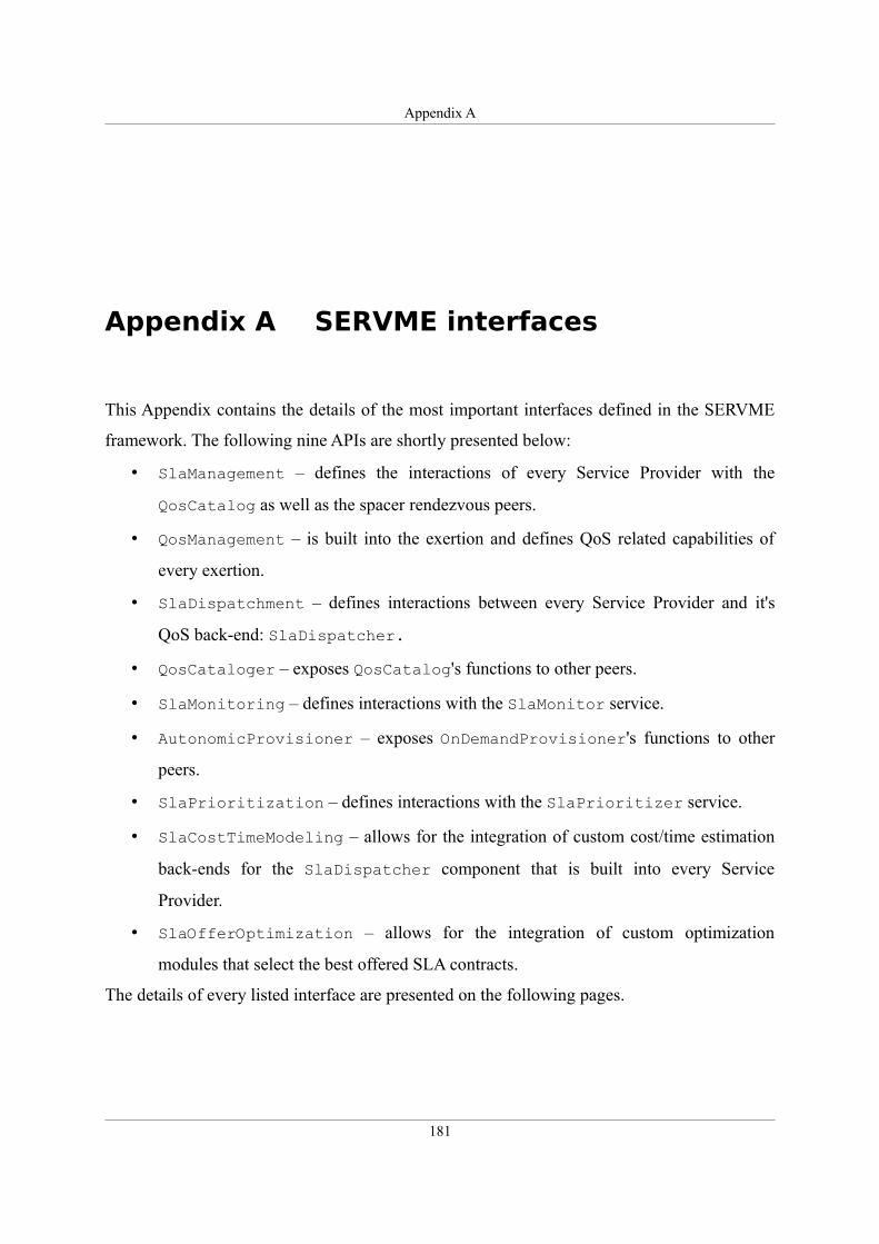
Appendix A
Appendix A SERVME interfaces
This Appendix contains the details of the most important interfaces defined in the SERVME
framework. The following nine APIs are shortly presented below:
• SlaManagement – defines the interactions of every Service Provider with the
QosCatalog as well as the spacer rendezvous peers.
• QosManagement – is built into the exertion and defines QoS related capabilities of
every exertion.
• SlaDispatchment – defines interactions between every Service Provider and it's
QoS back-end: SlaDispatcher.
• QosCataloger – exposes QosCatalog's functions to other peers.
• SlaMonitoring – defines interactions with the SlaMonitor service.
• AutonomicProvisioner – exposes OnDemandProvisioner's functions to other
peers.
• SlaPrioritization – defines interactions with the SlaPrioritizer service.
• SlaCostTimeModeling – allows for the integration of custom cost/time estimation
back-ends for the SlaDispatcher component that is built into every Service
Provider.
• SlaOfferOptimization – allows for the integration of custom optimization
modules that select the best offered SLA contracts.
The details of every listed interface are presented on the following pages.
181
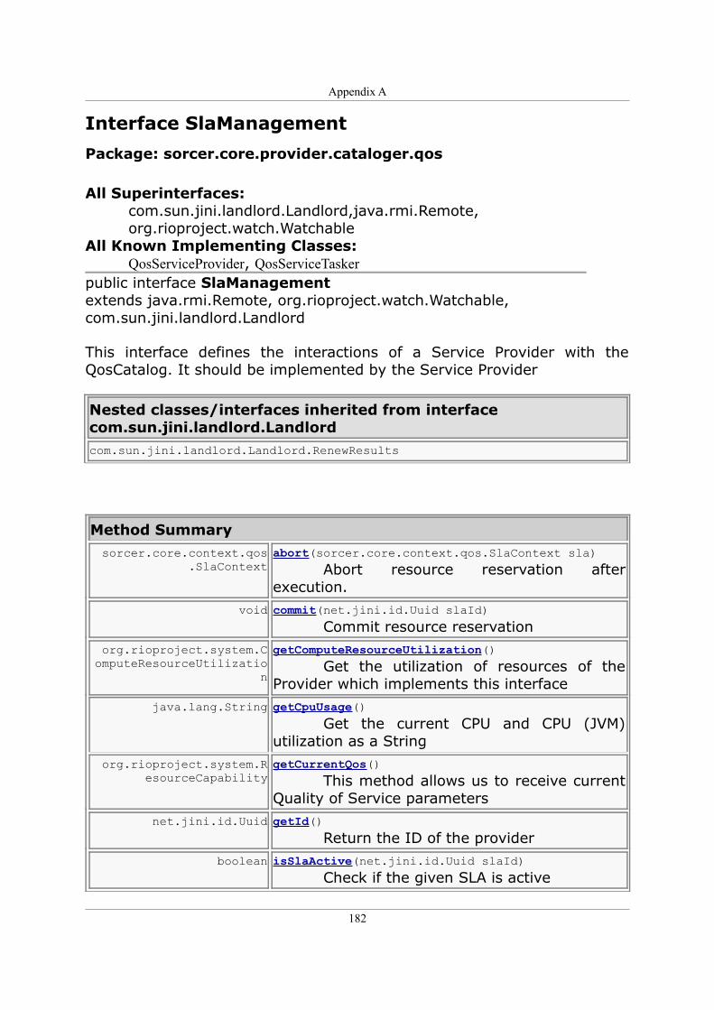
Appendix A
Interface SlaManagement
Package: sorcer.core.provider.cataloger.qos All Superinterfaces:
com.sun.jini.landlord.Landlord,java.rmi.Remote,org.rioproject.watch.Watchable
All Known Implementing Classes: QosServiceProvider, QosServiceTasker
public interface SlaManagementextends java.rmi.Remote, org.rioproject.watch.Watchable,com.sun.jini.landlord.Landlord
This interface defines the interactions of a Service Provider with the QosCatalog. It should be implemented by the Service Provider
Nested classes/interfaces inherited from interfacecom.sun.jini.landlord.Landlordcom.sun.jini.landlord.Landlord.RenewResults
Method Summary sorcer.core.context.qos
.SlaContextabort(sorcer.core.context.qos.SlaContext sla) Abort resource reservation after execution.
void commit(net.jini.id.Uuid slaId) Commit resource reservation
org.rioproject.system.ComputeResourceUtilizatio
n
getComputeResourceUtilization() Get the utilization of resources of the Provider which implements this interface
java.lang.String getCpuUsage() Get the current CPU and CPU (JVM) utilization as a String
org.rioproject.system.ResourceCapability
getCurrentQos() This method allows us to receive current Quality of Service parameters
net.jini.id.Uuid getId() Return the ID of the provider
boolean isSlaActive(net.jini.id.Uuid slaId) Check if the given SLA is active
182
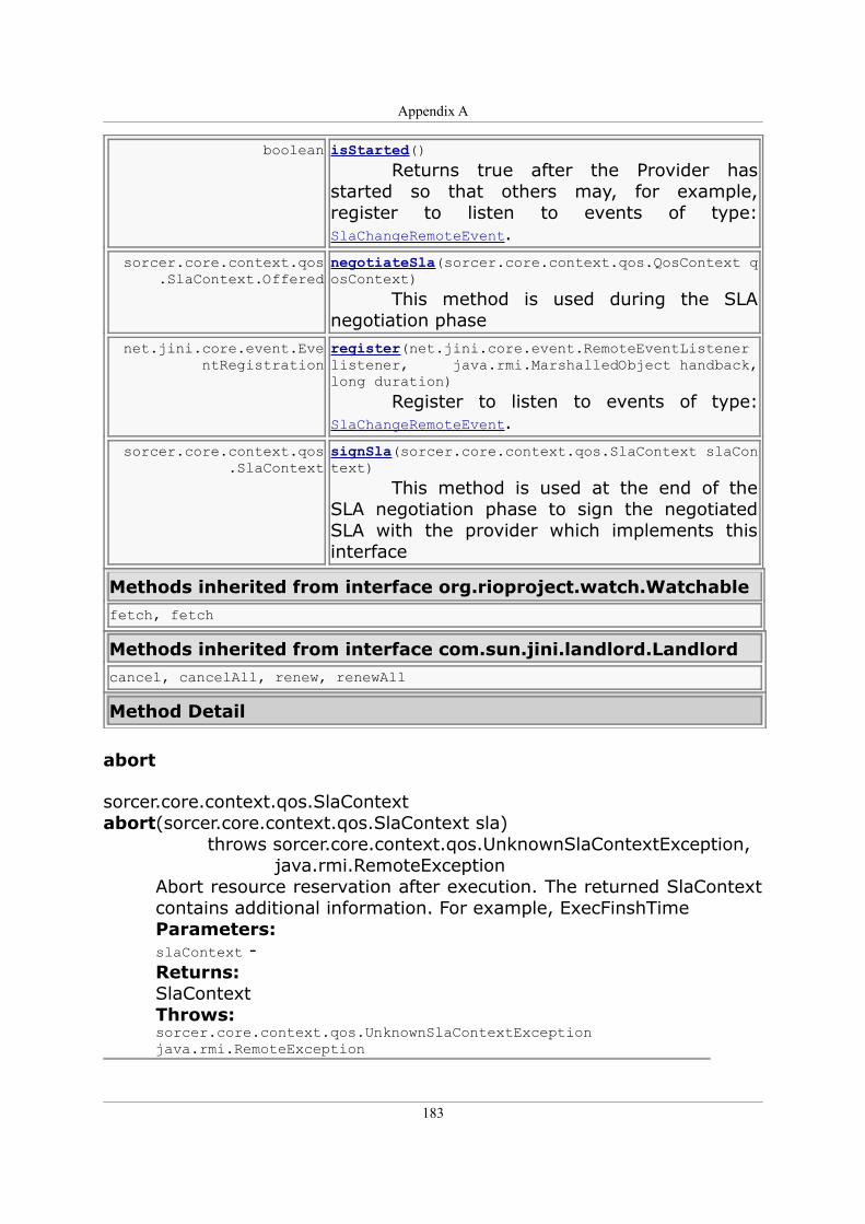
Appendix A
boolean isStarted() Returns true after the Provider has started so that others may, for example, register to listen to events of type: SlaChangeRemoteEvent.
sorcer.core.context.qos.SlaContext.Offered
negotiateSla(sorcer.core.context.qos.QosContext qosContext) This method is used during the SLA negotiation phase
net.jini.core.event.EventRegistration
register(net.jini.core.event.RemoteEventListener listener, java.rmi.MarshalledObject handback, long duration) Register to listen to events of type: SlaChangeRemoteEvent.
sorcer.core.context.qos.SlaContext
signSla(sorcer.core.context.qos.SlaContext slaContext) This method is used at the end of the SLA negotiation phase to sign the negotiated SLA with the provider which implements this interface
Methods inherited from interface org.rioproject.watch.Watchablefetch, fetch
Methods inherited from interface com.sun.jini.landlord.Landlordcancel, cancelAll, renew, renewAll
Method Detail
abort
sorcer.core.context.qos.SlaContext abort(sorcer.core.context.qos.SlaContext sla) throws sorcer.core.context.qos.UnknownSlaContextException, java.rmi.RemoteException
Abort resource reservation after execution. The returned SlaContext contains additional information. For example, ExecFinshTime Parameters: slaContext - Returns: SlaContext Throws: sorcer.core.context.qos.UnknownSlaContextException java.rmi.RemoteException
183
Appendix A
commit
void commit(net.jini.id.Uuid slaId) throws sorcer.core.context.qos.UnknownSlaContextException, java.rmi.RemoteException
Commit resource reservation Parameters: slaId - Throws: sorcer.core.context.qos.UnknownSlaContextException java.rmi.RemoteException
getComputeResourceUtilization
org.rioproject.system.ComputeResourceUtilization getComputeResourceUtilization() throws java.rmi.RemoteException
Get the utilization of resources of the Provider which implements this interface Returns: ComputeResourceUtilization Throws: java.rmi.RemoteException
getCpuUsage
java.lang.String getCpuUsage() throws java.rmi.RemoteException
Get the current CPU and CPU (JVM) utilization as a String Returns: String containing CPU and CPU (JVM) utilization Throws: java.rmi.RemoteException
getCurrentQos
org.rioproject.system.ResourceCapability getCurrentQos() throws java.rmi.RemoteException
This method allows us to receive current Quality of Service parameters Returns: ResourceCapbility - includes both PlatformCapabilities and MeasurableResources Throws: java.rmi.RemoteException
184
Appendix A
getId
net.jini.id.Uuid getId() throws java.rmi.RemoteException
Return the ID of the provider Returns: Uuid - id of provider Throws: java.rmi.RemoteException
isSlaActive
boolean isSlaActive(net.jini.id.Uuid slaId) throws java.rmi.RemoteException
Check if the given SLA is active Parameters: slaId - Returns: boolean Throws: java.rmi.RemoteException
isStarted
boolean isStarted() throws java.rmi.RemoteException
Returns true after the Provider has started so that others may, for example, register to listen to events of type: SlaChangeRemoteEvent. Returns: boolean Throws: java.rmi.RemoteException
negotiateSla
sorcer.core.context.qos.SlaContext.Offered negotiateSla(sorcer.core.context.qos.QosContext qosContext) throws QosProviderResourceException, java.rmi.RemoteException
This method is used during the SLA negotiation phase Parameters: qosContext - - containing the requirements of the requestor Returns: SlaContext - updated or offered by the provider which implements this interface
185
Appendix A
Throws: java.rmi.RemoteException QosProviderResourceException
register
net.jini.core.event.EventRegistration register(net.jini.core.event.RemoteEventListener listener, java.rmi.MarshalledObject handback, long duration) throws net.jini.core.lease.LeaseDeniedException, java.rmi.RemoteException
Register to listen to events of type: SlaChangeRemoteEvent. Those events are generated whenever the status of an SLA changes. Parameters: listener - handback - duration - Returns: EventRegistration Throws: net.jini.core.lease.LeaseDeniedException java.rmi.RemoteException
signSla
sorcer.core.context.qos.SlaContext signSla(sorcer.core.context.qos.SlaContext slaContext) throws java.rmi.RemoteException, QosProviderResourceException
This method is used at the end of the SLA negotiation phase to sign the negotiated SLA with the provider which implements this interface Parameters: slaContext - - containing the requirements of the requestor Returns: SlaContext - granted by the provider which implements this interface Throws: java.rmi.RemoteException QosProviderResourceException
186
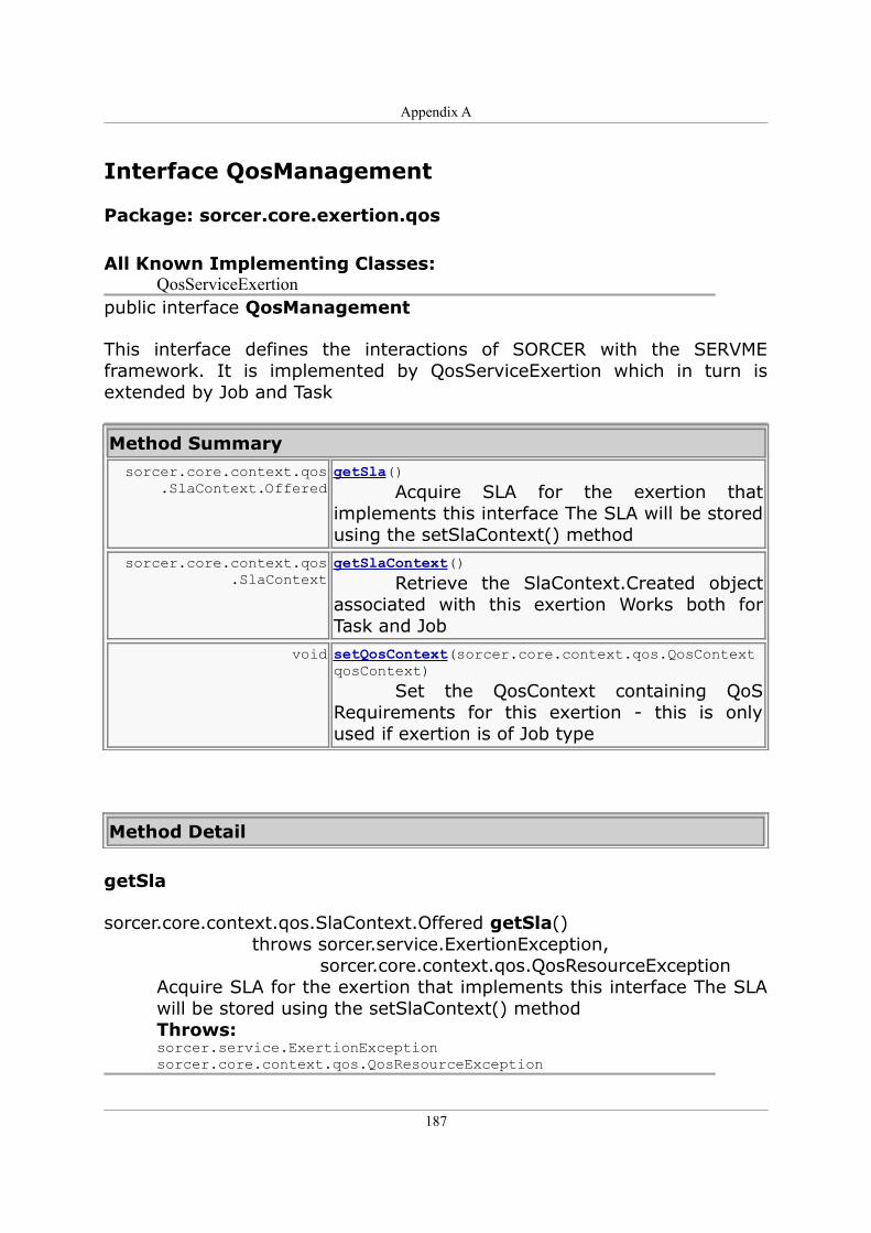
Appendix A
Interface QosManagement
Package: sorcer.core.exertion.qos
All Known Implementing Classes: QosServiceExertion
public interface QosManagement
This interface defines the interactions of SORCER with the SERVME framework. It is implemented by QosServiceExertion which in turn is extended by Job and Task
Method Summary sorcer.core.context.qos
.SlaContext.OfferedgetSla() Acquire SLA for the exertion that implements this interface The SLA will be stored using the setSlaContext() method
sorcer.core.context.qos.SlaContext
getSlaContext() Retrieve the SlaContext.Created object associated with this exertion Works both for Task and Job
void setQosContext(sorcer.core.context.qos.QosContext qosContext) Set the QosContext containing QoS Requirements for this exertion - this is only used if exertion is of Job type
Method Detail
getSla
sorcer.core.context.qos.SlaContext.Offered getSla() throws sorcer.service.ExertionException, sorcer.core.context.qos.QosResourceException
Acquire SLA for the exertion that implements this interface The SLA will be stored using the setSlaContext() method Throws: sorcer.service.ExertionException sorcer.core.context.qos.QosResourceException
187
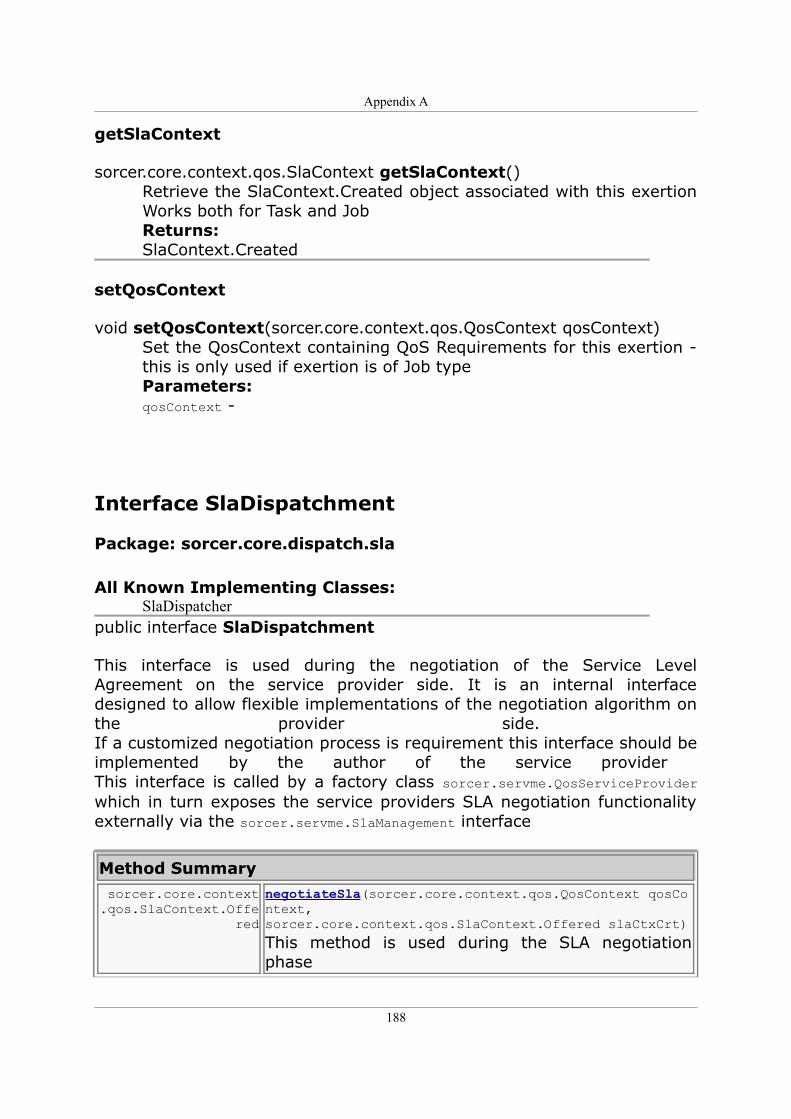
Appendix A
getSlaContext
sorcer.core.context.qos.SlaContext getSlaContext()Retrieve the SlaContext.Created object associated with this exertion Works both for Task and Job Returns: SlaContext.Created
setQosContext
void setQosContext(sorcer.core.context.qos.QosContext qosContext)Set the QosContext containing QoS Requirements for this exertion - this is only used if exertion is of Job type Parameters: qosContext -
Interface SlaDispatchment
Package: sorcer.core.dispatch.sla
All Known Implementing Classes: SlaDispatcher
public interface SlaDispatchment
This interface is used during the negotiation of the Service Level Agreement on the service provider side. It is an internal interface designed to allow flexible implementations of the negotiation algorithm on the provider side. If a customized negotiation process is requirement this interface should be implemented by the author of the service provider This interface is called by a factory class sorcer.servme.QosServiceProvider which in turn exposes the service providers SLA negotiation functionality externally via the sorcer.servme.SlaManagement interface
Method Summary sorcer.core.context.qos.SlaContext.Offe
red
negotiateSla(sorcer.core.context.qos.QosContext qosContext, sorcer.core.context.qos.SlaContext.Offered slaCtxCrt)
This method is used during the SLA negotiation phase
188
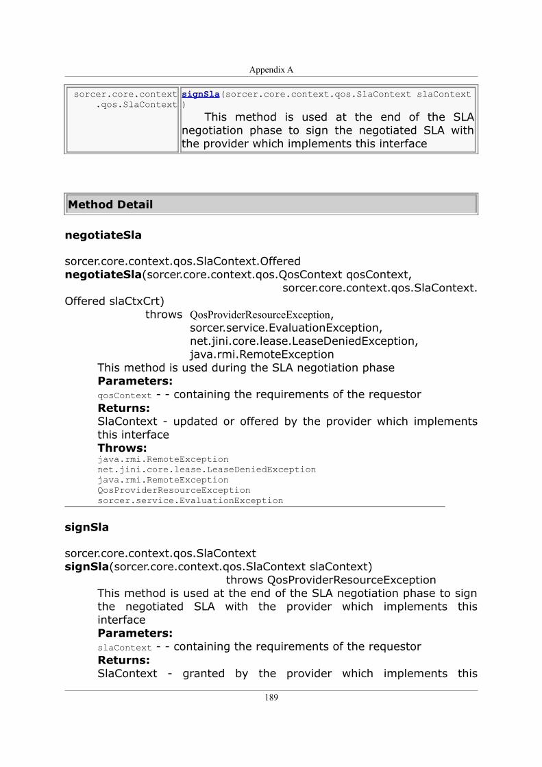
Appendix A
sorcer.core.context.qos.SlaContext
signSla(sorcer.core.context.qos.SlaContext slaContext) This method is used at the end of the SLA negotiation phase to sign the negotiated SLA with the provider which implements this interface
Method Detail
negotiateSla
sorcer.core.context.qos.SlaContext.Offered negotiateSla(sorcer.core.context.qos.QosContext qosContext, sorcer.core.context.qos.SlaContext.Offered slaCtxCrt) throws QosProviderResourceException, sorcer.service.EvaluationException, net.jini.core.lease.LeaseDeniedException, java.rmi.RemoteException
This method is used during the SLA negotiation phase Parameters: qosContext - - containing the requirements of the requestor Returns: SlaContext - updated or offered by the provider which implements this interface Throws: java.rmi.RemoteException net.jini.core.lease.LeaseDeniedException java.rmi.RemoteException QosProviderResourceException sorcer.service.EvaluationException
signSla
sorcer.core.context.qos.SlaContext signSla(sorcer.core.context.qos.SlaContext slaContext) throws QosProviderResourceException
This method is used at the end of the SLA negotiation phase to sign the negotiated SLA with the provider which implements this interface Parameters: slaContext - - containing the requirements of the requestor Returns: SlaContext - granted by the provider which implements this
189
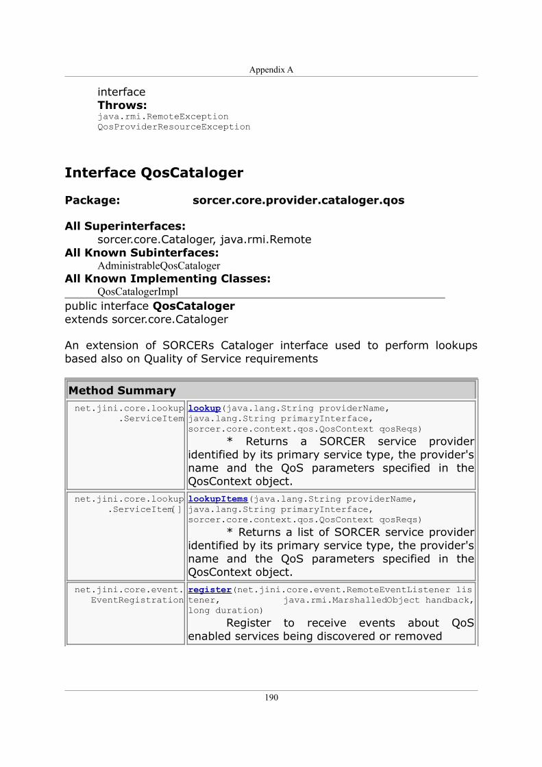
Appendix A
interface Throws: java.rmi.RemoteException QosProviderResourceException
Interface QosCataloger
Package: sorcer.core.provider.cataloger.qos
All Superinterfaces: sorcer.core.Cataloger, java.rmi.Remote
All Known Subinterfaces: AdministrableQosCataloger
All Known Implementing Classes: QosCatalogerImpl
public interface QosCatalogerextends sorcer.core.Cataloger
An extension of SORCERs Cataloger interface used to perform lookups based also on Quality of Service requirements
Method Summary net.jini.core.lookup
.ServiceItemlookup(java.lang.String providerName, java.lang.String primaryInterface, sorcer.core.context.qos.QosContext qosReqs) * Returns a SORCER service provider identified by its primary service type, the provider's name and the QoS parameters specified in the QosContext object.
net.jini.core.lookup.ServiceItem[]
lookupItems(java.lang.String providerName, java.lang.String primaryInterface, sorcer.core.context.qos.QosContext qosReqs) * Returns a list of SORCER service provider identified by its primary service type, the provider's name and the QoS parameters specified in the QosContext object.
net.jini.core.event.EventRegistration
register(net.jini.core.event.RemoteEventListener listener, java.rmi.MarshalledObject handback, long duration) Register to receive events about QoS enabled services being discovered or removed
190
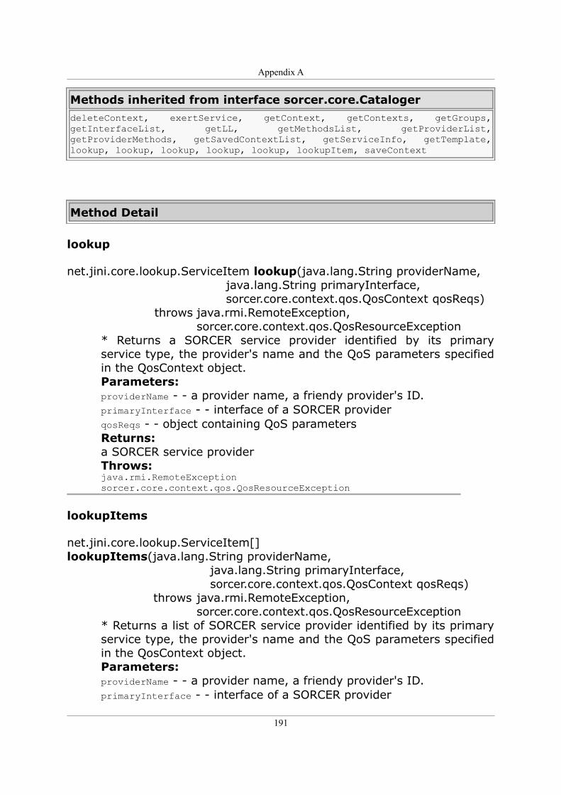
Appendix A
Methods inherited from interface sorcer.core.CatalogerdeleteContext, exertService, getContext, getContexts, getGroups, getInterfaceList, getLL, getMethodsList, getProviderList, getProviderMethods, getSavedContextList, getServiceInfo, getTemplate, lookup, lookup, lookup, lookup, lookup, lookupItem, saveContext
Method Detail
lookup
net.jini.core.lookup.ServiceItem lookup(java.lang.String providerName, java.lang.String primaryInterface, sorcer.core.context.qos.QosContext qosReqs) throws java.rmi.RemoteException, sorcer.core.context.qos.QosResourceException
* Returns a SORCER service provider identified by its primary service type, the provider's name and the QoS parameters specified in the QosContext object. Parameters: providerName - - a provider name, a friendy provider's ID. primaryInterface - - interface of a SORCER provider qosReqs - - object containing QoS parameters Returns: a SORCER service provider Throws: java.rmi.RemoteException sorcer.core.context.qos.QosResourceException
lookupItems
net.jini.core.lookup.ServiceItem[] lookupItems(java.lang.String providerName, java.lang.String primaryInterface, sorcer.core.context.qos.QosContext qosReqs) throws java.rmi.RemoteException, sorcer.core.context.qos.QosResourceException
* Returns a list of SORCER service provider identified by its primary service type, the provider's name and the QoS parameters specified in the QosContext object. Parameters: providerName - - a provider name, a friendy provider's ID. primaryInterface - - interface of a SORCER provider
191
Appendix A
qosReqs - - object containing QoS parameters Returns: a SORCER service provider Throws: java.rmi.RemoteException sorcer.core.context.qos.QosResourceException
register
net.jini.core.event.EventRegistration register(net.jini.core.event.RemoteEventListener listener, java.rmi.MarshalledObject handback, long duration) throws java.rmi.RemoteException, net.jini.core.lease.LeaseDeniedException
Register to receive events about QoS enabled services being discovered or removed Parameters: listener - handback - duration - Returns: EventRegistration Throws: java.rmi.RemoteException net.jini.core.lease.LeaseDeniedException
Interface SlaMonitoring
Package: sorcer.core.provider.qos.sla.slamonitor
All Superinterfaces: java.rmi.Remote
All Known Subinterfaces: AdministrableSlaMonitoring
All Known Implementing Classes: SlaMonitor
public interface SlaMonitoringextends java.rmi.Remote
Interface used to monitor Service Level Agreements. It is implemented by the SLA Monitor Service - SlaMonitor
192
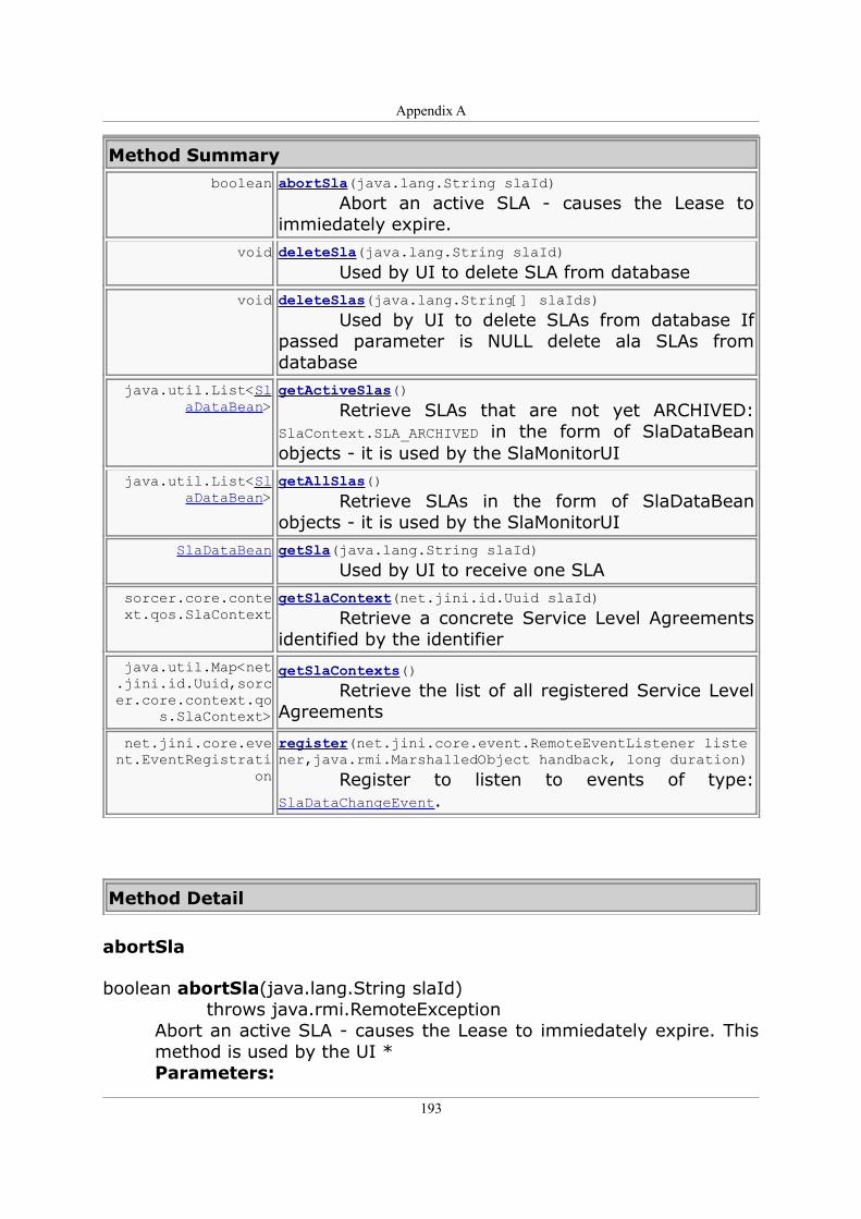
Appendix A
Method Summary boolean abortSla(java.lang.String slaId)
Abort an active SLA - causes the Lease to immiedately expire.
void deleteSla(java.lang.String slaId) Used by UI to delete SLA from database
void deleteSlas(java.lang.String[] slaIds) Used by UI to delete SLAs from database If passed parameter is NULL delete ala SLAs from database
java.util.List<SlaDataBean>
getActiveSlas() Retrieve SLAs that are not yet ARCHIVED: SlaContext.SLA_ARCHIVED in the form of SlaDataBean objects - it is used by the SlaMonitorUI
java.util.List<SlaDataBean>
getAllSlas() Retrieve SLAs in the form of SlaDataBean objects - it is used by the SlaMonitorUI
SlaDataBean getSla(java.lang.String slaId) Used by UI to receive one SLA
sorcer.core.context.qos.SlaContext
getSlaContext(net.jini.id.Uuid slaId) Retrieve a concrete Service Level Agreements identified by the identifier
java.util.Map<net.jini.id.Uuid,sorcer.core.context.qo
s.SlaContext>
getSlaContexts() Retrieve the list of all registered Service Level Agreements
net.jini.core.event.EventRegistrati
on
register(net.jini.core.event.RemoteEventListener listener,java.rmi.MarshalledObject handback, long duration) Register to listen to events of type: SlaDataChangeEvent.
Method Detail
abortSla
boolean abortSla(java.lang.String slaId) throws java.rmi.RemoteException
Abort an active SLA - causes the Lease to immiedately expire. This method is used by the UI * Parameters:
193
Appendix A
slaId - Returns: true if succeeded Throws: java.rmi.RemoteException
deleteSla
void deleteSla(java.lang.String slaId) throws java.rmi.RemoteException
Used by UI to delete SLA from database Parameters: slaId - Throws: java.rmi.RemoteException
deleteSlas
void deleteSlas(java.lang.String[] slaIds) throws java.rmi.RemoteException
Used by UI to delete SLAs from database If passed parameter is NULL delete ala SLAs from database Parameters: slaIds - Throws: java.rmi.RemoteException
getActiveSlas
java.util.List<SlaDataBean> getActiveSlas() throws java.rmi.RemoteException
Retrieve SLAs that are not yet ARCHIVED: SlaContext.SLA_ARCHIVED in the form of SlaDataBean objects - it is used by the SlaMonitorUI Returns: List Throws: java.rmi.RemoteException
getAllSlas
java.util.List<SlaDataBean> getAllSlas() throws java.rmi.RemoteException
Retrieve SLAs in the form of SlaDataBean objects - it is used by the SlaMonitorUI Returns:
194
Appendix A
List Throws: java.rmi.RemoteException
getSla
SlaDataBean getSla(java.lang.String slaId) throws java.rmi.RemoteException
Used by UI to receive one SLA Parameters: slaId - Returns: SlaDataBean Throws: java.rmi.RemoteException
getSlaContext
sorcer.core.context.qos.SlaContext getSlaContext(net.jini.id.Uuid slaId) throws java.rmi.RemoteException
Retrieve a concrete Service Level Agreements identified by the identifier Parameters: identifier - of the SLA to be retrieved Returns: SLA object Throws: java.rmi.RemoteException
getSlaContexts
java.util.Map<net.jini.id.Uuid,sorcer.core.context.qos.SlaContext> getSlaContexts() throws java.rmi.RemoteException
Retrieve the list of all registered Service Level Agreements Returns: Array of SLA objects Throws: java.rmi.RemoteException
register
net.jini.core.event.EventRegistration register(net.jini.core.event.RemoteEventListener listener, java.rmi.MarshalledObject handback,
195
Appendix A
long duration) throws net.jini.core.lease.LeaseDeniedException, java.rmi.RemoteException
Register to listen to events of type: SlaDataChangeEvent. Those events are generated whenever the status of an SLA changes. Parameters: listener - handback - duration - Returns: EventRegistration Throws: net.jini.core.lease.LeaseDeniedException java.rmi.RemoteException
Interface AutonomicProvisioner
Package: sorcer.core.provider.autonomic.provisioner.servme All Known Subinterfaces:
AdministrableAutonomicProvisioner All Known Implementing Classes:
AutonomicProvisionerImpl public interface AutonomicProvisioner
AutonomicProvisioner handles On-demand provisioning and deprovisioning of SORCER services using RIO
Method Summary java.util.Map deploy(java.lang.String providerInterface)
Deploy Service with the given providerInterface.
java.util.Map deploy(java.lang.String prvInterface, sorcer.core.context.qos.QosContext qosContext) Deploy Service with the given providerInterface and supplied SLAIf there are errors loading part of the OperationalString a Map will be returned with name value pairs associating the service and corresponding exception attempting to load the service element
196
Appendix A
java.util.Map deploy(java.lang.String prvInterface, sorcer.core.context.qos.QosContext qosContext, int minProviders) Deploy Service with the given providerInterface and supplied SLAIf there are errors loading part of the OperationalString a Map will be returned with name value pairs associating the service and corresponding exception attempting to load the service element
java.util.Map<java.lang.String,java.l
ang.Integer>
getCurrentlyProvisioned() Return a map of currently provisioned services: String providerInterface, Integer numberOfInstances
void load(java.lang.String providerInterface, org.rioproject.core.OperationalString opStr) Load OperationalString for this providerInterface
void load(java.lang.String provInterface,
java.net.URL url) Load OperationalString from URL for this providerInterface
net.jini.core.event.EventRegistration
register(net.jini.core.event.RemoteEventListener listener, java.rmi.MarshalledObject handback, long duration) Register to receive events about services being provisioned and unprovisioned
void remove(java.lang.String providerInterface) Remove OperationalString for this providerInterface
boolean undeploy(java.lang.String providerInterface) Undeploy service for the given providerInterface
Method Detail
deploy
java.util.Map deploy(java.lang.String providerInterface) throws java.rmi.RemoteException, ProvisionerException
Deploy Service with the given providerInterface.
197
Appendix A
If there are errors loading part of the OperationalString a Map will be returned with name value pairs associating the service and corresponding exception attempting to load the service element Parameters: providerInterface - Returns: Map of errors Throws: java.rmi.RemoteException ProvisionerException
deploy
java.util.Map deploy(java.lang.String prvInterface, sorcer.core.context.qos.QosContext qosContext) throws java.rmi.RemoteException, ProvisionerException
Deploy Service with the given providerInterface and supplied SLA If there are errors loading part of the OperationalString a Map will be returned with name value pairs associating the service and corresponding exception attempting to load the service element Parameters: providerInterface - Returns: Map of errors Throws: java.rmi.RemoteException ProvisionerException
deploy
java.util.Map deploy(java.lang.String prvInterface, sorcer.core.context.qos.QosContext qosContext, int minProviders) throws java.rmi.RemoteException, ProvisionerException
Deploy Service with the given providerInterface and supplied SLA If there are errors loading part of the OperationalString a Map will be returned with name value pairs associating the service and corresponding exception attempting to load the service element Parameters: providerInterface - qosContext - minProviders - Returns:
198
Appendix A
Map of errors Throws: java.rmi.RemoteException ProvisionerException
getCurrentlyProvisioned
java.util.Map<java.lang.String,java.lang.Integer> getCurrentlyProvisioned() throws java.rmi.RemoteException
Return a map of currently provisioned services: String providerInterface, Integer numberOfInstances Returns: Map Throws: java.rmi.RemoteException
load
void load(java.lang.String providerInterface, org.rioproject.core.OperationalString opStr) throws java.rmi.RemoteException
Load OperationalString for this providerInterface Parameters: provInterface - url - Throws: OpstringException java.rmi.RemoteException
load
void load(java.lang.String provInterface, java.net.URL url) throws OpstringException, java.rmi.RemoteException
Load OperationalString from URL for this providerInterface Parameters: provInterface - url - Throws: OpstringException java.rmi.RemoteException
register
net.jini.core.event.EventRegistration
199
Appendix A
register(net.jini.core.event.RemoteEventListener listener, java.rmi.MarshalledObject handback, long duration) throws java.rmi.RemoteException, net.jini.core.lease.LeaseDeniedException
Register to receive events about services being provisioned and unprovisioned Parameters: listener - handback - duration - Returns: EventRegistration Throws: java.rmi.RemoteException net.jini.core.lease.LeaseDeniedException
remove
void remove(java.lang.String providerInterface) throws java.rmi.RemoteException
Remove OperationalString for this providerInterface Parameters: providerInterface - Throws: java.rmi.RemoteException
undeploy
boolean undeploy(java.lang.String providerInterface) throws java.rmi.RemoteException, ProvisionerException
Undeploy service for the given providerInterface Parameters: providerInterface - Returns: true if the OperationalString has been undeployed Throws: java.rmi.RemoteException ProvisionerException
200
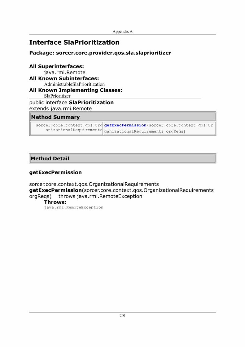
Appendix A
Interface SlaPrioritization
Package: sorcer.core.provider.qos.sla.slaprioritizer All Superinterfaces:
java.rmi.Remote All Known Subinterfaces:
AdministrableSlaPrioritization All Known Implementing Classes:
SlaPrioritizer public interface SlaPrioritizationextends java.rmi.Remote
Method Summary sorcer.core.context.qos.Org
anizationalRequirementsgetExecPermission(sorcer.core.context.qos.Or
ganizationalRequirements orgReqs)
Method Detail
getExecPermission
sorcer.core.context.qos.OrganizationalRequirements getExecPermission(sorcer.core.context.qos.OrganizationalRequirements orgReqs) throws java.rmi.RemoteException
Throws: java.rmi.RemoteException
201
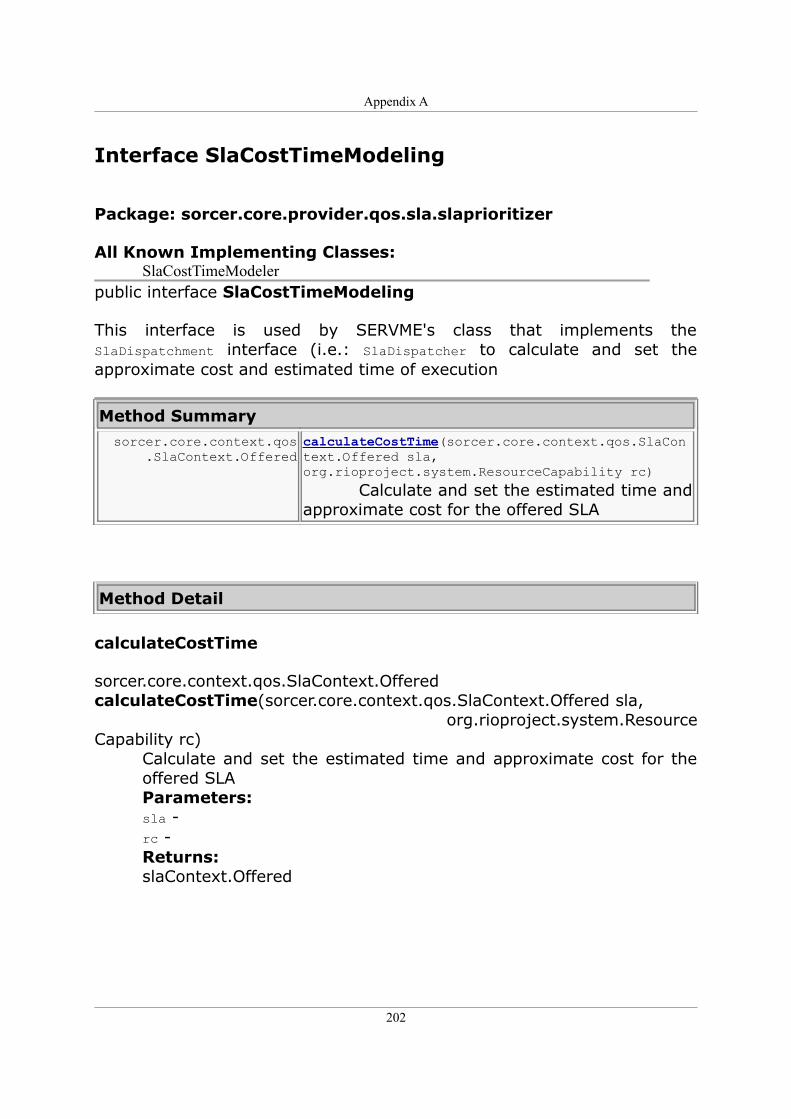
Appendix A
Interface SlaCostTimeModeling
Package: sorcer.core.provider.qos.sla.slaprioritizer
All Known Implementing Classes: SlaCostTimeModeler
public interface SlaCostTimeModeling
This interface is used by SERVME's class that implements the SlaDispatchment interface (i.e.: SlaDispatcher to calculate and set the approximate cost and estimated time of execution
Method Summary sorcer.core.context.qos
.SlaContext.OfferedcalculateCostTime(sorcer.core.context.qos.SlaContext.Offered sla,org.rioproject.system.ResourceCapability rc) Calculate and set the estimated time and approximate cost for the offered SLA
Method Detail
calculateCostTime
sorcer.core.context.qos.SlaContext.Offered calculateCostTime(sorcer.core.context.qos.SlaContext.Offered sla, org.rioproject.system.ResourceCapability rc)
Calculate and set the estimated time and approximate cost for the offered SLA Parameters: sla - rc - Returns: slaContext.Offered
202
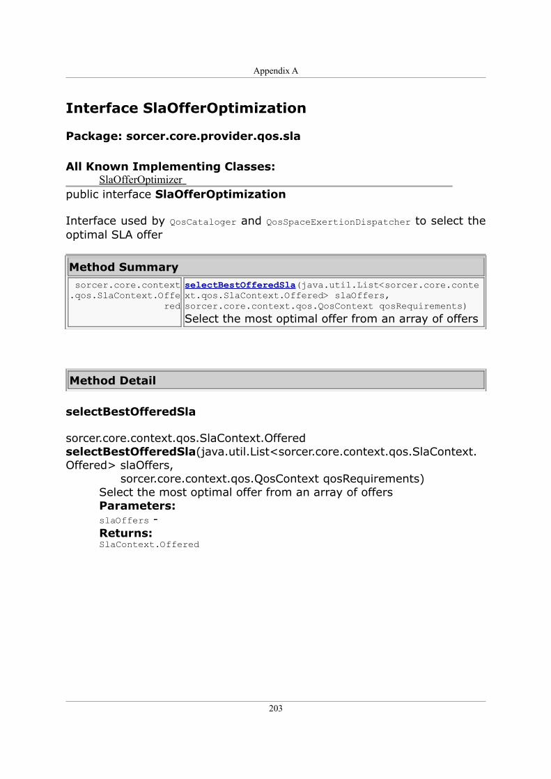
Appendix A
Interface SlaOfferOptimization
Package: sorcer.core.provider.qos.sla
All Known Implementing Classes: SlaOfferOptimizer
public interface SlaOfferOptimization
Interface used by QosCataloger and QosSpaceExertionDispatcher to select the optimal SLA offer
Method Summary sorcer.core.context.qos.SlaContext.Offe
red
selectBestOfferedSla(java.util.List<sorcer.core.context.qos.SlaContext.Offered> slaOffers, sorcer.core.context.qos.QosContext qosRequirements) Select the most optimal offer from an array of offers
Method Detail
selectBestOfferedSla
sorcer.core.context.qos.SlaContext.Offered selectBestOfferedSla(java.util.List<sorcer.core.context.qos.SlaContext.Offered> slaOffers, sorcer.core.context.qos.QosContext qosRequirements)
Select the most optimal offer from an array of offers Parameters: slaOffers - Returns: SlaContext.Offered
203