Optimal Polarization Synthesis of Arbitrary Arrays With ... · Optimal Polarization Synthesis of...
9
HAL Id: hal-00700707 https://hal.archives-ouvertes.fr/hal-00700707 Submitted on 23 May 2012 HAL is a multi-disciplinary open access archive for the deposit and dissemination of sci- entific research documents, whether they are pub- lished or not. The documents may come from teaching and research institutions in France or abroad, or from public or private research centers. L’archive ouverte pluridisciplinaire HAL, est destinée au dépôt et à la diffusion de documents scientifiques de niveau recherche, publiés ou non, émanant des établissements d’enseignement et de recherche français ou étrangers, des laboratoires publics ou privés. Optimal Polarization Synthesis of Arbitrary Arrays With Focused Power Pattern Benjamin Fuchs, Jean-Jacques Fuchs To cite this version: Benjamin Fuchs, Jean-Jacques Fuchs. Optimal Polarization Synthesis of Arbitrary Arrays With Fo- cused Power Pattern. IEEE Transactions on Antennas and Propagation, Institute of Electrical and Electronics Engineers, 2011, 59 (12), pp.4512-4519. <hal-00700707>
Transcript of Optimal Polarization Synthesis of Arbitrary Arrays With ... · Optimal Polarization Synthesis of...
HAL Id: hal-00700707https://hal.archives-ouvertes.fr/hal-00700707
Submitted on 23 May 2012
HAL is a multi-disciplinary open accessarchive for the deposit and dissemination of sci-entific research documents, whether they are pub-lished or not. The documents may come fromteaching and research institutions in France orabroad, or from public or private research centers.
L’archive ouverte pluridisciplinaire HAL, estdestinée au dépôt et à la diffusion de documentsscientifiques de niveau recherche, publiés ou non,émanant des établissements d’enseignement et derecherche français ou étrangers, des laboratoirespublics ou privés.
Optimal Polarization Synthesis of Arbitrary ArraysWith Focused Power Pattern
Benjamin Fuchs, Jean-Jacques Fuchs
To cite this version:Benjamin Fuchs, Jean-Jacques Fuchs. Optimal Polarization Synthesis of Arbitrary Arrays With Fo-cused Power Pattern. IEEE Transactions on Antennas and Propagation, Institute of Electrical andElectronics Engineers, 2011, 59 (12), pp.4512-4519. <hal-00700707>

4512 IEEE TRANSACTIONS ON ANTENNAS AND PROPAGATION, VOL. 59, NO. 12, DECEMBER 2011
Optimal Polarization Synthesis of Arbitrary ArraysWith Focused Power Pattern
Benjamin Fuchs, Member, IEEE, and Jean Jacques Fuchs, Member, IEEE
Abstract—The joint synthesis of the spatial power pattern andpolarization of arbitrary arrays is addressed. Specifically, theproposed approach gives the solution to a frequently encounteredproblem, namely the array design (i.e., the determination ofthe radiating element weightings) to achieve a pattern that isarbitrarily upper bounded, while its polarization is optimizedin a given angular region. Any state of polarization (elliptical,circular and linear) can be synthesized and there is no restrictionregarding the array geometry and element patterns. The synthesisproblem is rewritten as a convex optimization problem, that isefficiently solved using readily available software. This ensuresthe optimality of the proposed solution. Various numerical resultsare presented to validate the proposed method and illustrate itspotentialities. The synthesis of a sequentially rotated array is firstaddressed. Then a linear array of equispaced randomly orienteddipoles is considered. Finally, a conformal and a planar array ofpatches, where the mutual coupling effects are considered, aresynthesized to radiate a linear and a circular polarization.
Index Terms—Array pattern synthesis, conformal arrays,convex optimization, waveform polarization.
I. INTRODUCTION
E XPLOITING the polarization of a waveform has many ad-vantages. It enables, for instance, to improve the perfor-
mance of active sensing systems, such as radars [1]. Polarimetricradar systems have thus been developed and efficiently used invarious applications [2], [3]. Moreover, the polarization diver-sity has been shown to improve the performances of commu-nication systems. It indeed significantly increases the capacityof wireless communications [4]. The polarization diversity isalso effective to combat fading in mobile wireless communica-tions [5], [6] and to compensate for polarization mismatch dueto random handset orientation [7]. Investigations have also beenled to show the interest of using polarized arrays for interferencerejection in wireless communication systems [8], [9].
If the benefits of using polarized waveforms are well known,the way to generate them, i.e., the synthesis of polarized arrays,has been relatively few reported in the literature. Though thesynthesis of antenna arrays has received much attention overthe years [10], [11], most of these works focus on spatial power
Manuscript received November 05, 2010; revised April 08, 2011; acceptedJune 02, 2011. Date of publication August 18, 2011; date of current versionDecember 02, 2011.
B. Fuchs is with the Laboratory of Electromagnetics and Acoustics, EcolePolytechnique Fédérale de Lausanne, Switzerland on leave from the IETR/Uni-versity of Rennes I, Rennes Cedex 35042, France (e-mail: [email protected]).
J. J. Fuchs is with the IRISA/University of Rennes I, 35042 Rennes Cedex,France (e-mail: [email protected]).
Color versions of one or more of the figures in this paper are available onlineat http://ieeexplore.ieee.org.
Digital Object Identifier 10.1109/TAP.2011.2165492
pattern synthesis and thus consider that the field emitted by an-tenna arrays is scalar. These techniques are therefore not able tohandle the design of arrays having any elliptical polarization.
It is only quite recently that a few works dealing with the jointsynthesis of power pattern and polarization have been reportedin the literature. An iterative least square method is presentedin [12] to synthesize a main beam with optimized circular po-larization for conformal arrays. An analytic approximation ofcircular polarized patches is used to model the elements radi-ation pattern. The ideal shape of the far field radiation patternand the targeted polarization are defined as the desired radiationpattern in a least square optimization procedure.
An adaptive array approach is applied in [13] to a conformalantenna array to synthesize a main beam with optimized po-larization employing dual polarized patch antennas as radiatingelements.
The aforementioned synthesis methods can not ensure thatthe optimum is reached, since the optimization problems theysolve are not convex or not transformed into convex programs.The exploitation of convexity in array synthesis problems hasbeen introduced by [14] and applied, later on, to various classesof problems as reviewed in [15]. Such a convex formulation hasbeen proposed in [16] to optimally synthesize pencil beams.While the coupling is taken into account, arbitrarily definedupper bounds can be set on the co- and cross-polarization com-ponents of the field.
The optimal synthesis of beampattern having any stateof polarization via convex optimization has been addressedvery recently in [17]–[19] using an array of vector antennas,i.e., antennas composed of orthogonal electric or magneticdipoles. Specifically, the goal is to find the antenna weightingsthat achieve a pattern whose main beam pointing at a givendirection has a specified polarization, while the sidelobe levelis minimized. This vector array synthesis problem is cleverlytransformed into a scalar one using an orthogonal transforma-tion, which then makes the problem efficiently solvable.
In this paper, a method to jointly synthesize the spatial powerpattern and the polarization of arbitrary arrays is presented.Specifically, the proposed approach designs the array radiatingelement weightings to achieve a pattern whose power is subjectto arbitrary upper bounds, while its polarization is optimizedover an angular region. The search for the array elementweightings is formulated as a convex optimization problem.This ensures the optimality of the proposed solution that isobtained by transforming the problem into a second order coneprogram (SOCP) [20]. From now on, it is thus possible to solvethis frequently encountered synthesis problem in an efficientway.
0018-926X/$26.00 © 2011 IEEE
FUCHS AND FUCHS: OPTIMAL POLARIZATION SYNTHESIS OF ARBITRARY ARRAYS WITH FOCUSED POWER PATTERN 4513
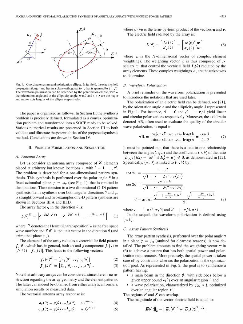
Fig. 1. Coordinate system and polarization ellipse. In far field, the electric fieldpropagates along �� and lies in a plane orthogonal to ��, that is spanned by ���� ���.The waveform polarization can be described by the polarization ellipse, with �the orientation angle and � the ellipticity angle. ��� � and ��� � are the majorand minor axis lengths of the ellipse respectively.
The paper is organized as follows. In Section II, the synthesisproblem is precisely defined, formulated as a convex optimiza-tion problem and transformed into a SOCP ready to be solved.Various numerical results are presented in Section III to bothvalidate and illustrate the potentialities of the proposed synthesismethod. Conclusions are drawn in Section IV.
II. PROBLEM FORMULATION AND RESOLUTION
A. Antenna Array
Let us consider an antenna array composed of elementsplaced at arbitrary but known locations with .The problem is described for a one-dimensional pattern syn-thesis. This synthesis is performed over the polar angle in afixed azimuthal plane (see Fig. 1), that is omitted inthe notations. The extension to a two-dimensional (2-D) patternsynthesis, i.e., a synthesis over both angular directions and ,is straightforward and two examples of 2-D pattern synthesis areshown in Sections III.A and III.D.
The array factor in the direction is:
(1)
where denotes the Hermitian transposition, is the free spacewave number and is the unit vector in the direction (andazimuthal plane ).
The element of the array radiates a vectorial far field pattern, which has, in general, both a and component:
. This leads to the following vectors:
(2)
(3)
Note that arbitrary arrays can be considered, since there is no re-striction regarding the array geometry and the element patterns.The latter can indeed be obtained from either analytical formula,simulation results or measured data.
The vectorial antenna array response is:
(4)
(5)
where is the term-by-term product of the vectors and .The electric field radiated by the array is:
(6)
where is the -dimensional vector of complex elementweightings. The weighting vector is thus composed ofscalars that control the vectorial field radiated by thearray elements. These complex weightings are the unknownsto determine.
B. Waveform Polarization
A brief reminder on the waveform polarization is presentedto introduce the notations that are used later.
The polarization of an electric field can be defined, see [21],by the orientation angle and the ellipticity angle representedin Fig. 1. For instance, and yield linearand circular polarizations respectively. Moreover, the axial ratiodenoted AR, often used to evaluate the quality of the circularwave polarization, is equal to:
(7)
It must be pointed out, that there is a one-to-one relationshipbetween the angles and the coefficients of the ratio
if , as demonstrated in [22].Specifically, is linked to by:
(8)
where and .In the sequel, the waveform polarization is defined using
.
C. Array Pattern Synthesis
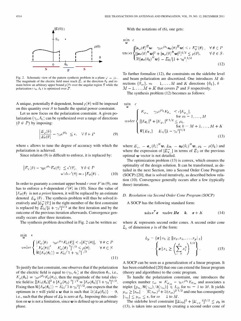
The array pattern synthesis, performed over the polar anglein a plane (omitted for clearness reasons), is now de-tailed. The problem amounts to find the weighting vector in(6) to achieve a pattern that has both spatial power and polar-ization requirements. More precisely, the spatial power is takencare of by constraints whereas the polarization is the optimiza-tion goal. As represented in Fig. 2, the goal is to synthesize apattern having:
• a main beam in the direction with sidelobes below agiven upper bound over an angular region and
• a wave polarization, characterized by , optimizedover an angular region .
The regions and can overlap.The magnitude of the vector electric field is equal to:
4514 IEEE TRANSACTIONS ON ANTENNAS AND PROPAGATION, VOL. 59, NO. 12, DECEMBER 2011
Fig. 2. Schematic view of the pattern synthesis problem in a plane � � � .The magnitude of the electric field must reach � at the direction � and re-main below an arbitrary upper bound ���� over the angular region � while thepolarization �� � � � is optimized over .
A unique, potentially -dependent, bound will be imposedon this quantity over to handle the spatial power constraint.
Let us now focus on the polarization constraint. A given po-larization can be synthesized over a range of directions
by imposing:
(9)
where allows to tune the degree of accuracy with which thepolarization is achieved.
Since relation (9) is difficult to enforce, it is replaced by:
(10)
In order to guaranty a constant upper bound over in (9), onehas to enforce a -dependent in (10). Since the value of
is not a priori known, it will be replaced by an estimatedenoted . The synthesis problem will thus be solved it-eratively and in the right member of the first constraintis replaced by at the first iteration and by theoutcome of the previous iteration afterwards. Convergence gen-erally occurs after three iterations.
The synthesis problem described in Fig. 2 can be written as:
(11)
To justify the last constraint, one observes that if the polarizationof the electric field is equal to at the direction , i.e.,
, then the magnitude of the total elec-tric field is: .Fixing then , one expects that theoptimum in will yield a that is such that ,i.e., such that the phase of is zero at . Imposing this condi-tion on is not a limitation, since is defined up to an arbitraryphase.
With the notations of (6), one gets:
(12)
To further formalize (12), the constraints on the sidelobe leveland beam polarization are discretized. One introduces di-rections and directions
that covers and respectively.The synthesis problem (12) becomes as follows:
(13)
where andwhere the expression of in terms of or the previousoptimal vector is not detailed.
The optimization problem (13) is convex, which ensures theoptimality of the design solution. It can be transformed, as de-tailed in the next Section, into a Second Order Cone Program(SOCP) [20], that is solved iteratively, as described below rela-tion (10). Convergence generally occurs after a few (typicallythree) iterations.
D. Resolution via Second Order Cone Program (SOCP)
A SOCP has the following standard form:
(14)
where represents second order cones. A second order coneof dimension is of the form:
(15)
A SOCP can be seen as a generalization of a linear program. Ithas been established [20] that one can extend the linear program(theory and algorithms) to the conic program.
To handle the polarization constraint, one introduces thecomplex number and associates atriplet , for to . It yields
and one has consequently, for to .
The sidelobe level constraint in(13), is taken into account by creating a second order cone of
FUCHS AND FUCHS: OPTIMAL POLARIZATION SYNTHESIS OF ARBITRARY ARRAYS WITH FOCUSED POWER PATTERN 4515
dimension 5: .It implies that:
(16)
which leads to for .Standard transformations, namely the use of slack variables,
are then used to rewrite the inequalities of (11) into equalities,as required in (14).
Note that the use of SOCP in (16) allows to constrain pre-cisely the magnitude of the vector field:
This is indeed a much weaker constraint than imposing, as donein [13], [16], an upper bound on the two components of the field,e.g., and , with
.Once the possibly delicate transcription of the synthesis
problem into a SOCP (as described above) has been performed,the existence of free software that solve efficiently SOCP,without any further tuning, justifies largely its use. To solvethe SOCP (14), the optimization toolbox SeDuMi [25] is used.More examples of synthesis problems using SOCP are given in[23], [24].
III. NUMERICAL RESULTS
In this Section, numerical results are presented to validateand illustrate the potentialities of the proposed approach. Letus remind that any state of polarization in (10) can besynthesized, but in the examples below, only linear and circularpolarization are considered. They corresponds respectively tothe minimization of and . In the case of thelinear polarization synthesis, relation (10) becomes then
and the synthesis procedure requires therefore no iteration.First, a sequentially rotated array composed of dipoles is de-
signed to radiate a circularly polarized wave in order to validatethe method. Then, a linear array of dipoles is synthesized to ra-diate a pattern with a spatial power constraint and an optimizedpolarization. The synthesis of a conformal array, where the cou-pling effects are taken into account, is also presented. Finally, atwo-dimensional (2-D) pattern synthesis problem is addressedfor a planar array composed of randomly oriented patches.
A. Validation: Sequentially Rotated Array
The approach, described in Section II, is here extended in astraightforward way to the synthesis of 2-D patterns. A de-pendency has to be considered in the (1) to (13).
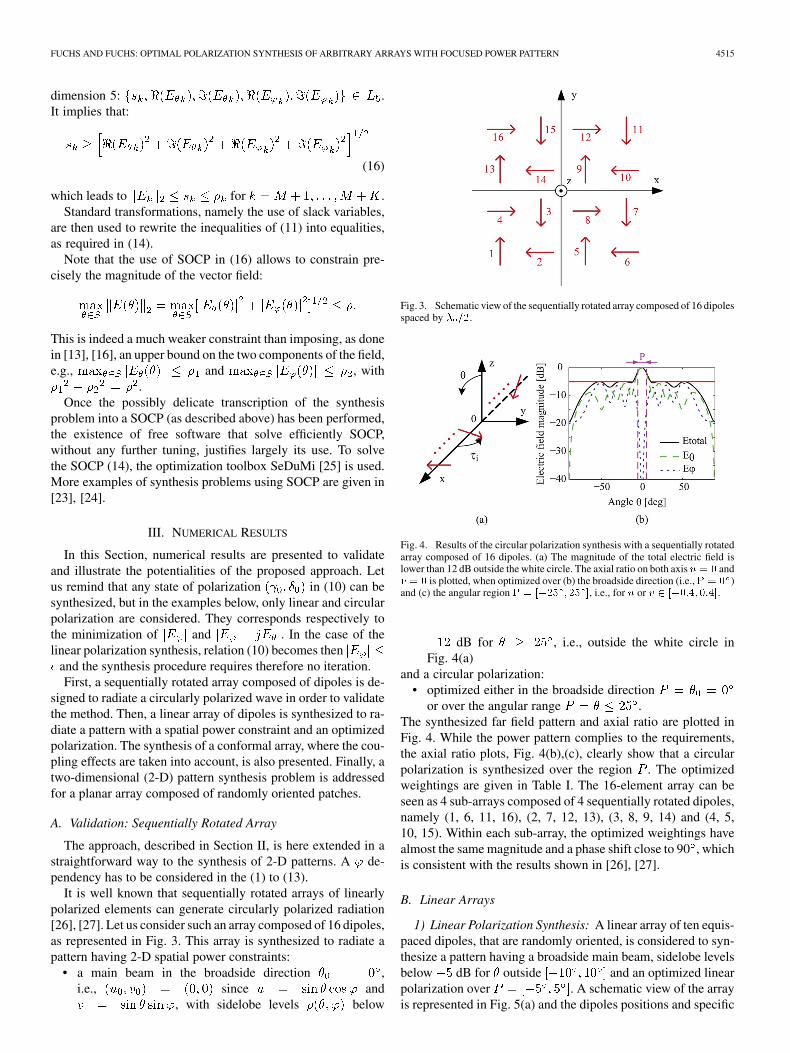
It is well known that sequentially rotated arrays of linearlypolarized elements can generate circularly polarized radiation[26], [27]. Let us consider such an array composed of 16 dipoles,as represented in Fig. 3. This array is synthesized to radiate apattern having 2-D spatial power constraints:
• a main beam in the broadside direction ,i.e., since and
, with sidelobe levels below
Fig. 3. Schematic view of the sequentially rotated array composed of 16 dipolesspaced by � ��.
Fig. 4. Results of the circular polarization synthesis with a sequentially rotatedarray composed of 16 dipoles. (a) The magnitude of the total electric field islower than 12 dB outside the white circle. The axial ratio on both axis � � � and� � � is plotted, when optimized over (b) the broadside direction (i.e., � � � )and (c) the angular region � � ���� � �� �, i.e., for � or � � ������ ����.
dB for , i.e., outside the white circle inFig. 4(a)
and a circular polarization:• optimized either in the broadside direction
or over the angular range .The synthesized far field pattern and axial ratio are plotted inFig. 4. While the power pattern complies to the requirements,the axial ratio plots, Fig. 4(b),(c), clearly show that a circularpolarization is synthesized over the region . The optimizedweightings are given in Table I. The 16-element array can beseen as 4 sub-arrays composed of 4 sequentially rotated dipoles,namely (1, 6, 11, 16), (2, 7, 12, 13), (3, 8, 9, 14) and (4, 5,10, 15). Within each sub-array, the optimized weightings havealmost the same magnitude and a phase shift close to 90 , whichis consistent with the results shown in [26], [27].
B. Linear Arrays
1) Linear Polarization Synthesis: A linear array of ten equis-paced dipoles, that are randomly oriented, is considered to syn-thesize a pattern having a broadside main beam, sidelobe levelsbelow dB for outside and an optimized linearpolarization over . A schematic view of the arrayis represented in Fig. 5(a) and the dipoles positions and specific

4516 IEEE TRANSACTIONS ON ANTENNAS AND PROPAGATION, VOL. 59, NO. 12, DECEMBER 2011
TABLE IOPTIMAL WEIGHTINGS OF THE SEQUENTIALLY ROTATED ARRAY SYNTHESIS
orientations together with the optimal weightings are given inTable II.
The synthesized far field patterns are shown in Fig. 5(b).While the magnitude of the total field complies to the sidelobelevel constraint, is at least 16.8 dB lower than over ,which confirms the linear polarization of the wave.
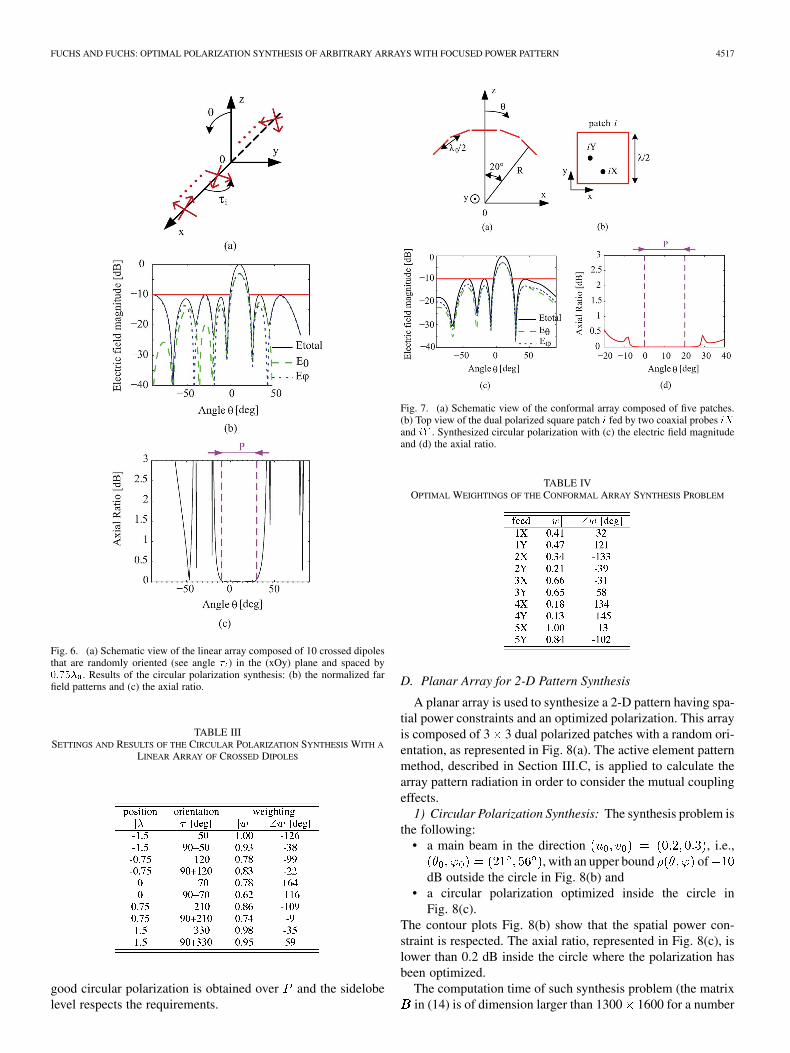
2) Circular Polarization Synthesis: A linear array of tencrossed dipoles, that are randomly oriented and spaced by
, is considered to synthesize a main beam in the direc-tion with an optimized circular polarization over
. The sidelobe levels are constrained to remainbelow dB over . A schematicview of the array is represented in Fig. 6(a) and the dipolespositions and orientations are given in Table III.
The synthesized far field patterns Fig. 6(b) show that the spa-tial power constraints are well respected. Moreover, the andcomponents of the field have the same magnitude over . Thisis confirmed by the axial ratio, plotted in Fig. 6(c), that is lowerthan 0.1 dB over , which establishes the good quality of thesynthesized circular polarization.
C. Conformal Array
An array of five patches that are conformed on a cylinder, asrepresented in Fig. 7(a), is considered. Each square patch is fedby two coaxial probes and , as shown in Fig. 7(b). Eachelement is therefore dually polarized.
The goal is to find the complex weightings of eachcoaxial probe in order to radiate a main beam in the di-rection with sidelobe levels below dB for
and an optimized circularpolarization over .
The active element pattern method [28] is applied to calculatethe pattern of the fully excited array. Each patch is simulated inthe array environment with a full wave numerical software (An-soft HFSS) to provide the array response and of (6). Usingthis method enables one to take the mutual coupling effects intoaccount.
The optimal weightings of the conformal array synthesisproblem are given in Table IV. The synthesized far field patterns
Fig. 5. (a) Schematic view of the linear array composed of 10 dipoles that arerandomly oriented (see angle � ) in the (xOy) plane and spaced by ���� . (b)Far field patterns of the linear polarization synthesis.
TABLE IISETTINGS AND RESULTS OF THE LINEAR POLARIZATION SYNTHESIS WITH A
LINEAR ARRAY OF DIPOLES
and the resulting axial ratio are plotted in Fig. 7(c),(d). A very
FUCHS AND FUCHS: OPTIMAL POLARIZATION SYNTHESIS OF ARBITRARY ARRAYS WITH FOCUSED POWER PATTERN 4517
Fig. 6. (a) Schematic view of the linear array composed of 10 crossed dipolesthat are randomly oriented (see angle � ) in the (xOy) plane and spaced by����� . Results of the circular polarization synthesis: (b) the normalized farfield patterns and (c) the axial ratio.
TABLE IIISETTINGS AND RESULTS OF THE CIRCULAR POLARIZATION SYNTHESIS WITH A
LINEAR ARRAY OF CROSSED DIPOLES
good circular polarization is obtained over and the sidelobelevel respects the requirements.
Fig. 7. (a) Schematic view of the conformal array composed of five patches.(b) Top view of the dual polarized square patch � fed by two coaxial probes ��and �� . Synthesized circular polarization with (c) the electric field magnitudeand (d) the axial ratio.
TABLE IVOPTIMAL WEIGHTINGS OF THE CONFORMAL ARRAY SYNTHESIS PROBLEM
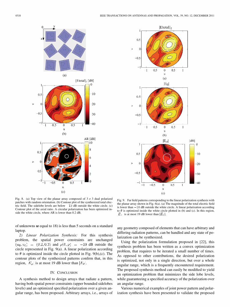
D. Planar Array for 2-D Pattern Synthesis
A planar array is used to synthesize a 2-D pattern having spa-tial power constraints and an optimized polarization. This arrayis composed of 3 3 dual polarized patches with a random ori-entation, as represented in Fig. 8(a). The active element patternmethod, described in Section III.C, is applied to calculate thearray pattern radiation in order to consider the mutual couplingeffects.
1) Circular Polarization Synthesis: The synthesis problem isthe following:
• a main beam in the direction , i.e.,, with an upper bound of
dB outside the circle in Fig. 8(b) and• a circular polarization optimized inside the circle in
Fig. 8(c).The contour plots Fig. 8(b) show that the spatial power con-straint is respected. The axial ratio, represented in Fig. 8(c), islower than 0.2 dB inside the circle where the polarization hasbeen optimized.
The computation time of such synthesis problem (the matrixin (14) is of dimension larger than 1300 1600 for a number
4518 IEEE TRANSACTIONS ON ANTENNAS AND PROPAGATION, VOL. 59, NO. 12, DECEMBER 2011
Fig. 8. (a) Top view of the planar array composed of 3� 3 dual polarizedpatches with random orientation. (b) Contour plot of the synthesized total elec-tric field. The sidelobe levels are below ��� dB outside the white circle. (c)Contour plot of the axial ratio. A circular polarization has been optimized in-side the white circle, where AR is lower than 0.2 dB.
of unknowns equal to 18) is less than 5 seconds on a standardlaptop.
2) Linear Polarization Synthesis: For this synthesisproblem, the spatial power constraints are unchanged
and dB outside thecircle represented in Fig. 9(a). A linear polarization accordingto is optimized inside the circle plotted in Fig. 9(b),(c). Thecontour plots of the synthesized patterns confirm that, in thisregion, is at most 19 dB lower than .
IV. CONCLUSION
A synthesis method to design arrays that radiate a pattern,having both spatial power constraints (upper bounded sidelobeslevels) and an optimized specified polarization over a given an-gular range, has been proposed. Arbitrary arrays, i.e., arrays of
Fig. 9. Far field patterns corresponding to the linear polarization synthesis withthe planar array shown in Fig. 6(a). (a) The magnitude of the total electric fieldis lower than ��� dB outside the white circle. A linear polarization accordingto � is optimized inside the white circle plotted in (b) and (c). In this region,�� � is at most 19 dB lower than �� �.
any geometry composed of elements that can have arbitrary anddiffering radiation patterns, can be handled and any state of po-larization can be synthesized.
Using the polarization formulation proposed in [22], thissynthesis problem has been written as a convex optimizationproblem, that requires to be iterated a small number of times.As opposed to other contributions, the desired polarizationis optimized, not only in a single direction, but over a wholeangular range, which is a frequently encountered requirement.The proposed synthesis method can easily be modified to yieldan optimization problem that minimizes the side lobe levels,while guaranteeing a specified accuracy of the polarization overan angular range.
Various numerical examples of joint power pattern and polar-ization synthesis have been presented to validate the proposed
FUCHS AND FUCHS: OPTIMAL POLARIZATION SYNTHESIS OF ARBITRARY ARRAYS WITH FOCUSED POWER PATTERN 4519
approach and to show its potentialities. The design of a sequen-tially rotated array has first been considered to ascertain thatthe proposed approach recovers the expected weightings. Arbi-trary linear and planar arrays as well as a conformal array havebeen synthesized to radiate both linear and circular polarizationto show the flexibility of our approach. The mutual couplingeffects between elements have been also taken into account inthe synthesis procedure by applying the active element patternmethod. Finally, the extension to the synthesis of two-dimen-sional power pattern with optimized polarization has been ad-dressed to show the efficiency of the approach in terms of com-putation load.
ACKNOWLEDGMENT
The authors would like to thank the reviewers for their com-ments that helped improve the paper as well as M. Kupka Diasda Silva for fruitful discussions.
REFERENCES
[1] D. G. Giuli, “Polarization diversity in radars,” Proc. IEEE, vol. 74, pp.245–269, Feb. 1986.
[2] M. A. Sletten and D. B. Trizna, “An ultrawideband, polarimetric radarfor the studies of sea scatter,” IEEE Trans. Antennas Propag., vol. 42,no. 11, pp. 1461–1466, Nov. 1994.
[3] J. Vivekanandan, V. N. Bringi, M. Hagen, and P. Meischner, “Polari-metric radar studies of atmospheric ice particles,” IEEE Trans. Geosci.Remote Sensing, vol. 32, no. 1, pp. 1–10, Jan. 1994.
[4] M. R. Andrews, P. P. Mitra, and R. De Carvalho, “Tripling the capacityof wireless communications using electromagnetic polarization,” Na-ture, vol. 409, pp. 316–318, Jan. 2001.
[5] W. C. Y. Lee and Y. S. Yeh, “Polarization diversity system for mobileradio,” IEEE Trans. Commun., vol. 26, pp. 912–923, Oct. 1972.
[6] C. B. Dietrich, K. Dietze, J. R. Nealy, and W. L. Stutzman, “Spatial, po-larization, and pattern diversity for wireless handheld terminals,” IEEETrans. Antennas Propag., vol. 49, no. 9, pp. 1271–1281, Sept. 2001.
[7] D. C. Cox, “Antenna diversity performance in mitigating the effects ofportable radio telephone orientation and multipath propagation,” IEEETrans. Commun., vol. 31, no. 5, pp. 620–628, May 1983.
[8] R. T. Compton, Jr., “The tripole antenna: An adaptive array with fullpolarization flexibility,” IEEE Trans. Antennas Propag., vol. 29, no. 6,pp. 944–952, Nov. 1981.
[9] A. J. Weiss and B. Friedlander, “Performance analysis of diversely po-larized antenna arrays,” IEEE Trans. Signal Processing, vol. 39, no. 7,pp. 1589–1603, Jul. 1991.
[10] A. Schell and A. Ishimaru, “Antenna pattern synthesis,” in AntennaTheory, R. E. Collin and F. J. Zucker, Eds. New York: McGraw-Hill,1969, ch. 10, pt. 1.
[11] W. L. Stutzman and G. A. Thiele, Antenna Theory and Design. NewYork: Wiley, 1981, ch. 10.
[12] L. I. Vaskelainen, “Iterative least-squares synthesis methods for con-formal array antennas with optimized polarization and frequency prop-erties,” IEEE Trans. Antennas Propag., vol. 45, no. 7, pp. 1179–1185,Jul. 1997.
[13] C. Dohmen, J. W. Odendaal, and J. Joubert, “Synthesis of conformalarrays with optimized polarization,” IEEE Trans. Antennas Propag.,vol. 55, no. 10, pp. 2922–2925, Oct. 2007.
[14] H. Lebret and S. Boyd, “Antenna pattern synthesis via convex opti-mization,” IEEE Trans. Signal Processing, vol. 45, no. 3, pp. 526–531,Mar. 1997.
[15] O. M. Bucci, M. D’Urso, and T. Isernia, “Exploiting convexity inarray antenna synthesis problems,” presented at the IEEE Radar Conf.,Roma, Italy, May 2008.
[16] L. Caccavale, T. Isernia, and F. Soldovieri, “Methods for optimal fo-cusing of microstrip array antennas including mutual coupling,” IEEMicrow. Antennas Propag., vol. 147, no. 3, pp. 199–202, Jun. 2000.
[17] J.-J. Xiao and A. Nehorai, “Optimal beam pattern synthesis of a polar-ized array,” presented at the IEEE Statistical Signal Processing Work-shop, Madison, WI, Aug. 2007.
[18] J.-J. Xiao and A. Nehorai, “Performance of beampattern synthesisusing high-dimensional vector antenna arrays,” presented at theSensor, Signal and Information Processing Workshop, Sedona, AZ,May 2008.
[19] J.-J. Xiao and A. Nehorai, “Optimal polarized beampattern synthesisusing a vector-antenna array,” IEEE Trans. Signal Processing, vol. 57,no. 2, pp. 576–587, Feb. 2009.
[20] A. Ben-Tal and A. S. Nemirovski, “Lectures on modern convexoptimization: Analysis, algorithms, and engineering applications,” inSociety for Industrial and Applied Mathematics. Philadelphia, PA:MPS-SIAM, 2001.
[21] G. A. Deschamps, “Part II—Geometrical representation of the po-larization of a plane electromagnetic wave,” Proc. IRE, vol. 39, pp.540–544, May 1951.
[22] A. Nehorai and E. Paldi, “Vector-sensor array processing for electro-magnetic source localization,” IEEE Trans. Signal Processing, vol. 42,no. 2, pp. 376–398, Feb. 1994.
[23] S. P. Boyd and L. Vandenberghe, Convex Optimization. Cambridge,U.K.: Cambridge Univ. Press, 2004.
[24] B. Fuchs and J. J. Fuchs, “Optimal narrow beam low sidelobe synthesisfor arbitrary arrays,” IEEE Trans. Antennas Propag., vol. 58, no. 6, pp.2130–2135, Jun. 2010.
[25] SeDuMi [Online]. Available: http://sedumi.ie.lehigh.edu/[26] T. Teshirogi, M. Tanaka, and W. Chujo, “Wideband circularly polar-
ized array antenna with sequential rotations and phase shift of ele-ments,” in Proc. of ISAP, 1985, pp. 117–120.
[27] J. Huang, “A technique for an array to generate circular polarizationwith linearly polarized elements,” IEEE Trans. Antennas Propag., vol.34, no. 9, pp. 1113–1124, Sep. 1986.
[28] D. F. Kelley and W. L. Stutzman, “Array antenna pattern modelingmethods that include mutual coupling effects,” IEEE Trans. AntennasPropag., vol. 41, no. 12, pp. 1625–1632, Dec. 1993.
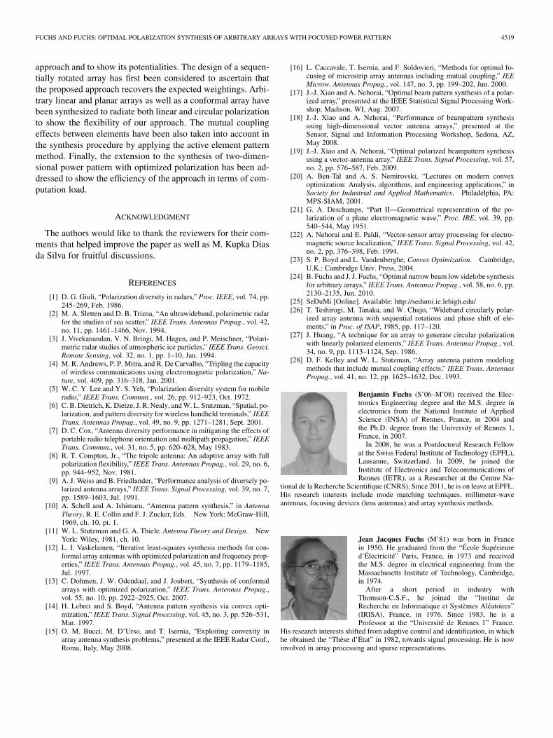
Benjamin Fuchs (S’06–M’08) received the Elec-tronics Engineering degree and the M.S. degree inelectronics from the National Institute of AppliedScience (INSA) of Rennes, France, in 2004 andthe Ph.D. degree from the University of Rennes 1,France, in 2007.
In 2008, he was a Postdoctoral Research Fellowat the Swiss Federal Institute of Technology (EPFL),Lausanne, Switzerland. In 2009, he joined theInstitute of Electronics and Telecommunications ofRennes (IETR), as a Researcher at the Centre Na-
tional de la Recherche Scientifique (CNRS). Since 2011, he is on leave at EPFL.His research interests include mode matching techniques, millimeter-waveantennas, focusing devices (lens antennas) and array synthesis methods.
Jean Jacques Fuchs (M’81) was born in Francein 1950. He graduated from the “École Supérieured’Électricité” Paris, France, in 1973 and receivedthe M.S. degree in electrical engineering from theMassachusetts Institute of Technology, Cambridge,in 1974.
After a short period in industry withThomson-C.S.F., he joined the “Institut deRecherche en Informatique et Systèmes Aléatoires”(IRISA), France, in 1976. Since 1983, he is aProfessor at the “Université de Rennes 1” France.
His research interests shifted from adaptive control and identification, in whichhe obtained the “Thèse d’Etat” in 1982, towards signal processing. He is nowinvolved in array processing and sparse representations.