Optimal integration of a self sustained algae based...
22
1 Optimal integration of a self sustained algae based facility with solar and/or wind energy Mariano Martín a1 , Ignacio E. Grossmann b a Department of Chemical Engineering. University of Salamanca. Pza. Caídos 1-5, 37008 Salamanca (Spain) b Department of Chemical Engineering. Carnegie Mellon University. 5000 Forbes Ave. 15213. Pittsburgh, PA Abstract. In this work we develop a conceptual design for an integrated facility that produces biodiesel (FAME) using solar and/or wind energy and CO2. Microalgae are grown to accumulate lipids that are extracted. The methanol needed for the transesterification is synthesized from CO2 and electrolytic hydrogen. The electricity for the complex is produced using solar panels or wind turbines. The flowsheet is formulated as a multiperiod MINLP problem whose solution provides the optimal source of energy and the operating conditions over a year for an average production of 60 Mgal/yr of FAME. The facility requires an investment of 112 M€ for a production cost of 0.79€/gal (0.25 €/kg). The energy consumption is 3.2 MJ/gal of FAME capturing 4.05 kg CO2 per kg of FAME and consuming 1L/L of water including the operation of the cooling tower and the boiler. Keywords: Solar Energy; Biomass; Wind power; Synthetic methanol; Hydrogen; CO2 1 Corresponding Author. M Martín: [email protected]
Transcript of Optimal integration of a self sustained algae based...

1
Optimal integration of a self sustained algae
based facility with solar and/or wind energy
Mariano Martína1, Ignacio E. Grossmannb
a Department of Chemical Engineering. University of Salamanca. Pza. Caídos 1-5, 37008 Salamanca (Spain)
b Department of Chemical Engineering. Carnegie Mellon University. 5000 Forbes Ave. 15213. Pittsburgh, PA
Abstract.
In this work we develop a conceptual design for an integrated facility that produces biodiesel
(FAME) using solar and/or wind energy and CO2. Microalgae are grown to accumulate lipids that are
extracted. The methanol needed for the transesterification is synthesized from CO2 and electrolytic
hydrogen. The electricity for the complex is produced using solar panels or wind turbines. The flowsheet is
formulated as a multiperiod MINLP problem whose solution provides the optimal source of energy and the
operating conditions over a year for an average production of 60 Mgal/yr of FAME. The facility requires an
investment of 112 M€ for a production cost of 0.79€/gal (0.25 €/kg). The energy consumption is 3.2 MJ/gal
of FAME capturing 4.05 kg CO2 per kg of FAME and consuming 1L/L of water including the operation of the
cooling tower and the boiler.
Keywords: Solar Energy; Biomass; Wind power; Synthetic methanol; Hydrogen; CO2
1 Corresponding Author. M Martín: [email protected]

2
1.-Introduction
Biodiesel is widely considered a biofuel, using methanol in the transesterification of the oil. While
the use of methanol has been justified from technical and economic points of view, faster reaction times and
cheaper than any other alcohol, not many studies have pointed out that methanol is typically produced from
coal or natural gas. Therefore, the second most important raw material in the current biodiesel industry is
actually a fossil based chemical. Ethanol can also be used as transesterification agent. Martín & Grossmann
(2013a) designed a facility that used ethanol produced out of the same algae for the production of biodiesel,
Fatty acid ethyl ester (FAEE). The biodiesel production cost was competitive with that produced from fossil
methanol and algae oil, and no fossil fuel based raw material was needed. However, methanol can also be
produced from either residues of the biodiesel industry or wastes. Martín & Grossmann (2013b) evaluated
the production of methanol from glycerol reforming to be used in the production of FAME. However, only two
thirds of the needs for methanol could be covered in this way and the production cost was higher compared
with buying the methanol. CO2 concentration in atmosphere has surpassed 400ppm recently (Montaigne,
2013) and, in an attempt to find further uses, it is being evaluated as a carbon source for chemicals. It has
been shown that CO2 can be hydrogenated to produce methane, although the production costs are high,
Davis and Martín (2014). However, CO2 can also be used to produce methanol via hydrogentation (Van-Dal
and Bouallow,2013) and different life cycle evaluations from LCA (Trudewind, et al 2014a) to Well to Wheel
analysls Trudewind, et al 2014b) have been presented. Therefore, the production of biodiesel from
renewable raw materials requires the integration of renewable resources (Alwi et al 2012) using the
philosophy of total site integration (Varbanov and Klemes, 2013).
While the use of CO2 as raw material is interesting from the environmental and technical points of
view, we are reusing a waste, the sustainability of the hydrogenation of CO2 relies on the use of renewables
to produce hydrogen. Actually the idea is old, but is its not until recently that it is being used (Levene et al
2005). Wind and solar energy can be used to produce the electricity that breaks down water into hydrogen
and oxygen for further use. The advantage of producing chemicals out of these intermittent sources of
energy is the fact that we can store the energy in a more useful state. Biomass can also be used to produce
hydrogen, but in that case we are not fully using the biomass since we lose the carbon.

3
Therefore, in this paper we integrate the production of algae from CO2 and solar energy and
methanol using solar or wind energy, water and CO2, designing an integrated facility for the mitigation of
CO2 while producing liquid fuels. The disadvantage of using sustainable sources of energy such as
biomass, wind and solar is the variability during a year in a region. Therefore, the design of such a plant
must be evaluated as a function of the availability of the energy sources, wind (Archer and Jacobson, 2004)
or solar (Sancho-Ávila et al 2013). The paper is organized as follows. In section 2 we describe the process.
Next, in section 3 we discuss the main modeling assumptions and solution procedures for the formulated
multiperiod MINLP problem. Subsequently, in section 4 we present results of the facility operation over a
year long and an economic evaluation. Finally, in Section 5 we draw some conclusions.
2.-Process description.
The process consists of four sections. Algae oil production, water electrolysis, methanol synthesis
and biodiesel production. Figure 1 shows the scheme for the integrated facility.
Figure 1.- Renewable resources integration for the production of biodiesel
2.1.Algae oil production. The production of oil and starch from algae is performed by injecting CO2 into the water, which can
be saline water so that the consumption of freshwater is reduced, together with air and fertilizers, see Figure
2. The amount of make-up water needed, 0.006 kg per kg of biomass, and the concentration of fertilizers,
0.14 kg per kg of dry biomass, is taken from the report by Pate (2008) while the consumption of CO2
depends on the growth rate (Sazdanoff, 2006)
We assume that the dry algae biomass is composed of lipids, starch and protein with 50% being
lipids. Together with the algae, oxygen is produced and water is evaporated (Pate, 2008).The energy
consumed by the pond system is calculated based on the results by Sazdanoff (2006). Next, the algae are
harvested from the pond. This stage has typically been the most energy intensive. However, Univenture Inc.
has presented an innovative technology capable of integrating harvesting and drying the algae with low
energy consumption. It is based on the use of capillarity, membrane systems and paint drying to get 5% wet
algae with a consumption of 40W for 500L/h of flow. The biomass is mixed with cyclo-hexane and pressed
so that oil is extracted and the biomass is recovered from oil. The biomass can be used to obtain energy for

4
the system, or it can also be further treated to obtain glucose and protein. The oil is used for
transesterification and biodiesel production.
Figure 2.- Algae oil production
2.2.-Methanol Synthesis:
As it can be seen in Figure 3, we consider an electrolyzer that breaks the water into hydrogen and
oxygen operating at 80ºC and 101 kPa a solution of 25% of KOH as electrolyte.
2 H2O → 2 H2 + O2 (1)
The energy for such an operation may come from wind turbines, solar panels, and/or the biogas
generated from the biomass after oil extraction. On the one hand, the line of oxygen carries water vapor and
traces of hydrogen. The water is condensed and the resulting stream dehydrated using a zeolite adsorber.
Finally, the oxygen is compressed and stored. On the other hand, we have the stream of hydrogen
containing traces of oxygen and water vapor. Most of the water is separated by condensation. The oxygen
represents a challenge for further synthetic stages, and thus, it is eliminated using a deoxygenation reactor
where water is produced. Next, a zeolite is used to dehydrate the stream. At this point, the hydrogen is
mixed with the CO2. The gas phase is adjusted for the optimal operating conditions using a compressor and
a heat exchanger. Methanol is produced based on a series of equilibria carried out over a catalyst, typically
Cu/ZnO/Al2O3. The optimal working conditions (ratio of H2 and CO and working temperature and pressure at
the reactor) are optimized. Unreacted gases are separated from the methanol and recycled back to the
reactor, while the methanol is purified used at the transesterification reactor. For details of the process and
the model we refer to the literature (Davis and Martín, 2014b).
Figure 3.- Methanol production
2.3.- Biodiesel synthesis
The use of heterogeneous catalysts for the production of biodiesel simplifies the purification stages
since the catalyst can easily be removed from the products, or they can be packed in the reactor (Martín and
Grossmann, 2012). Therefore, the process is simpler, see Figure 4.The reactants are prepared and fed to
the reactor. The transesterification can be represented by eq. (2).
Oil + 3 Alcohol ↔ 3 Biodiesel + Glycerol (2)

5
After the reactor, a distillation column is used to recover the excess of methanol. The bottoms of
the distillation column contain mainly glycerol and biodiesel with small amounts of methanol, water, FFA and
oil. A gravity separation allows the recovery of glycerol with a purity higher than 92%, while the biodiesel is
purified in a distillation column.
Figure 4.-Oil transesterification.
The aim is to optimize the topology and the operating conditions minimizing the production cost to
design a hybrid facility for the sustainable production of biodiesel using renewable resources taking into
account the variation of wind and solar energy. We propose a conceptual design based on the optimization
of a superstructure embedding the various process units involving solar or wind energy, algae growth, water
electrolysis, CO2 usage to produce methanol, and oil transesterfication to biodiesel. The optimization of the
superstructure is formulated as a multiperiod MINLP problem, where the model involves a set of constraints
representing mass and energy balances for all the units in the system with monthly variations. While the
operation of such facilities requires more details hourly analysis, the conceptual design is assumed to be
carried out on a monthly grid. An economic evaluation is performed to determine the effect of the chemicals
and raw materials costs on the design selection, and on the production cost of the optimal conceptual
design.
3.-Modelling.
In this section we describe the main assumptions used in modeling the process for the production
of synthetic methanol using wind / solar power and CO2 to be used for the production of biodiesel. We use
mass and energy balances, design equations, thermodynamic equilibrium and experimental data in order to
develop models for all the units involved in the process. For the sake of the length of the paper, we refer to
previous papers for more detailed modeling features of certain units related to hydrogen production (Marín
and Davis, 2014) and algae growing and biodiesel synthesis (Martín and Grossmann, 2012).
3.1.-Oil production and transesterification
3.1.1.-Oil production
The detailed modeling for the production of oil can be seen in the supplementary material of (Martín
and Grossmann, 2012). However, for this formulation we apply that model on a monthly basis where the
6
growth rate of the algae is a function of the solar energy as given by Park et al. (2011), eq (3), where I0
(kWh/m2/d) is the solar intensity, ηmax, the utilization of the light by the algae, 0.045 (Walker, 2009), and the
algae heating value is 21 kJ/g (Park et al 2011) :
0 max·algae heating value
IGrowth
η= (3)
The CO2 consumption rate is given by eq. (4), Sazdanoff (2006):
3
2 2
mCO 0.6565·Growth 5.0784gd m d
= +
(4)
The accumulation of oil in the algae ranges from 40 to 65% of the dry weight (Sazdanoff, 2006). A
value that can be conservative is to assume that the oil represents 50% of the dry biomass. A solvent and
mechanical press are used to extract the soil. Next, the mixture solvent and oil are separated in vacuum
distillation column. The oil is sent to transesterification and the solvent is recycled. We use a short cut model
for the column (Biegler et al 1997), validated with CHEMCAD.
3.1.2.- Oil transesterification
Martín & Grossmann (2012) proved that the use of heterogeneous catalysis was promising due to
the easy separation of the products. There is no need for biodiesel washing, reducing also the water
consumption of the facility, and it is more robust to process different oil sources. Therefore, the reactor is
modeled using a surface response model developed in the above mentioned paper given by eq. (5). Table 1
shows the lower and upper bounds of the operating conditions.
2
2 2
yield 73.6 2.5·T 24.9·Cat 8.8·ratio _ met 0.01·T
1.29·Cat 0.39·ratio _ met 0.26·T ·CatTrans Trans
Trans
= − + + + − −
− − (5)
Table 1.-Range of operation of the variables. Heterogeneous catalyzed
We recover the methanol using a distillation column Next, polar and non polar phases are
separated at 40ºC. The glycerol phase and the biodiesel phase have to be further purified. Vacuum
distillation columns are used for methanol recovery and biodiesel purification to avoid glycerol and FAME
decomposition, and modeled using a short cut method (Biegler et al 1997), validated with CHEMCAD. Thus,
the bottoms of the methanol recovery column and the distillate of the biodiesel purification tower should be
below 150ºC and 250ºC, respectively.

7
3.2.-Solar and wind sources
For a detailed description of the model related to the production of hydrogen and oxygen we refer
the reader to [15].
3.1.1-Wind Turbine power
We use the same turbine as in a previous paper(Davis and Martín, 2014), GE 1.5sle type (SAM,
2013). The power produced in this turbine is modeled by eq. (6) where P rated =1500kW, v is the average
wind velocity, a=8.322 (m/s) and m=0.806 (s/m) .
( )( )1rated
v a m
PP
e − −=
+ (6)
3.1.2-Solar panel installation
The PV panel of 8m2 that capable of using 75% of the solar energy that Earth receives is selected.
The installation cost ranges from 1700 to 4000 $/kWp (Maaben et al 2011) installed with a target of
1000$/kWp (Goodrich et al 2012). 1kWp requires typically those 8 m2 of panel. Thus, we assume 2300€ per
panel.
3.1.3.-Hydrogen production and purification.
The power required to produce one kg of hydrogen is 175,000 kJ (NEL, 2012). In the electrolyzer,
the water that is lost per unit of time, is not only given by water breakage, eq. (2), but also due to the
evaporation, since the gas phases exit the electrolyzer saturated with water. For costing purposes, each
electrolyzer generates 0.0124 kg H2 per second (NEL, 2012). Both streams, either the one rich in O2, or the
one rich in H2, are compressed. We considered the use of polytropic compressors with an efficiency of 0.85
and k =1.4 based on rules of thumb (Wallas, 1990). The stream consisting of mainly oxygen is first
compressed in a three stage compressor system with intercooling using a pressure ratio of 5. After the first
stage, we dehydrate the stream using zeolites. Similarly, the hydrogen stream is compressed to 500kPa so
as to dehydrate it. Thus, zeolite adsorbants are used with a removal ratio of 99.97%. The dehydration of the
oxygen takes place at 25ºC, after the first compression and subsequent cooling. The hydrogen stream is
dehydrated after the deoxygenation at 90ºC. The Desoxo reaction is used to remove the traces of oxygen
from the hydrogen stream following eq. (8). We assume a conversion of 99.97%.
2 H2 + O2 2 H2O (8)

8
3.3..-Synthesis Loop
The synthesis of the methanol is based on the hydrogenation of CO2 (Chinchen et al 1988). Two
reactions take place, apart from the methanol synthesis from CO2 hydrogenation, the reverse water-gas-
shift (RWGS) reaction also occurs , eq. (9)
2 2 3 2
2 2 2
CO 3H CH OH H O CO H CO H O
+ ↔ ++ ↔ +
(9)
Thermodynamically, the synthesis of methanol from CO2 hydrogenation is less favored compared
to that from CO, and it has a smaller heat of reaction. The reactor is modeled assuming equilibrium, where
the elementary balances to the carbon, hydrogen and oxygen atoms must hold as well as the species
equilibria. The values of the equilibrium constants for reactions given by eq. (9), are computed using eqs.
(10-11) (Chinchen et al 1988).
H: ( )2 2 32 2H H CH OHH O H Oin out
2·n +2·n - 2·n +2·n +4·n =0;
C: ( )2 2 3n +n +n 0;CO CO CO CO CH OHin out
n n+ − = (10)
O: ( )2 2 2 2 32· n 2·n +n +n 0;CO CO H O CO CO H O CH OHin out
n n n+ + − + =
[ ]
3 8 23 2
22
2
2 2
9143.622.225 7.492 ( ) 4.076·10 · 7.161·10 ·
23
4 7 22 2
5639.5 4917013.148 1.077 ln 5.44 10 1.125 10
Ln T T TCH OH H O Ta
HCO
CO H Oa
CO H
P PK e
P P
P PK Exp T x T x T
T TP P
− − + − + −
− −
=
= = − − − + +
11)
3.4.-Raw materials
3.4.1.- CO2
We selected a region given by the availability of CO2 from power plants and high wind velocity, over
class 3 (Archer, 2004). For our case study we locate the plant in the Gulf of Cadiz. But the formulation can
be applied to any other region.
3.4.2.-Wind/Solar/Biomass availability
Table 2 shows the data on the availability of solar energy and wind velocity over a year in the
selected allocation. Furthermore, using eq. (1) we have computed the monthly algae growth rate.
9
Figure 5.- Resource availability in Spain (Sancho-Ávila, 2012; ARCHER 2004, CESR 2006]
Table 2 Monthly solar and wind availability [Windtrends, 2014; Junta de Andalucía, 2014]
3.5.-Solution procedure
This problem is formulated as a multiperiod MINLP of the following general formulation
1min ( ) ( , )
. ( , ) 0 t=1,...,
t tt
t t
Z C d f d x
st g d x
Γ
=
= +
≤ Γ
∑ (P0)
Where d are the design variables, some of them integer, and xt are variables corresponding to the
operation at each time period f.
We can address the solution of such a problem in several ways. The most computationally
expensive requires the definition of all the mass and energy flows as a function of the period, a set of
equations determining the mass and energy balances per month as indicated in P0. That multiplies the
problem size by approximately the number of periods. The methods presented by Varvarezos et al either
using an outer approximation (Varvarezos et al 1992) or an SQP decomposition (Varvarezos et al 1994)
can be used to address the problem. Alternatively, we can take advantage of the knowledge of the operation
of chemical plants, that is to say, the mass and energy balances are proportional to the operation of any
month that can be taken as a reference. We assume that the optimal operating pressures, temperatures,
chemical equilibria for the reactors and vapor – liquid equilibria are the same in each month. Thus, only the
flows will change. Thus, we fix the annual production capacity to match the typical one for bioethanol /
biodiesel plants, around 60MGal/yr (Martín and Grossmann, 2013c). The process may not operate at their
full monthly capacity all year long, and therefore an efficiency is defined, effy(month). The oil produced on a
monthly basis determines the needs for methanol for its transesterification. The methanol is produced via
electrolytic hydrogen and CO2.
To formulate the problem in a general form, we consider two groups of equations. Those whose
operation is not directly affected by the atmospheric conditions, gII, i.e. processing steps, and those that
depend on the input from the atmosphere, gI, either in the form of raw materials (water, air) or renewable
energy (wind velocity, solar o cooling systems):

10
1
int , ,
int , ,
min ( ) ( , )
.( , , ) 0 t=1,...,
( , , ) 0 t=1,...,
t tt
I ensive I extensive It t tII ensive II extensive IIt t t
Z C d f d x
stg d w wg d w w
Γ
=
= +
≤ Γ
≤ Γ
∑ (P1)
The first group must remain untouched since its evaluation is directly dependent on time dependent
variables. However, for the second group we can decompose it as follows. We consider a reference time
interval for which the model of the process is written. The operating variables are computed as a function of
that reference:
{ }
1
int , ,
int , ,
int , int ,
int ,
min ( ) ( , )
.( , , ) 0
( , , , ) 0
intensive ,
t tt
I ensive I extensive It t tII ensive II extensive IIref ref ref ref
ensive II ensive IIt ref
ensive II extensit t ref t
Z C d f d x
stg d w wg d w w
w w P T
w w
θ
η α
Γ
=
= +
≤
≤
= ∈
=
∑
{ }
{ }
,
int
int , ,
extensive , , ,
( , , , , )
0,1
(atmospheric conditions) ( , ), 1,...,
ve II
ensive extensivet ref ref t
t
ensive I extensive It t t
fc F Q W
f t d w w
f f w w t
α θ
η
θ
∈
=
∈
= = = Γ
(P1)
Where,α is a scale-up factor since the productivity of the system depends on the energy provided
by the Sun or wind for instance. η is the factor that determines whether the system operates at the fully
capacity of based on the availability of resources at a given time or not. If other raw materials are involved,
such as freshwater or air at atmospheric conditions, we still need to maintain those as variable with time and
evaluate the influence in the process.
Thus, the mass and energy balances presented in sections 3.1 and 3.2 are defined for a reference
month, gII . The operating pressures and temperatures of each unit are determined for this month and
assumed constant over time. Equation (12) represents the operation of the plant in a certain reference
month identifying the set of equations corresponding with gII:
Mass and energy balances (T,P)reference (12)

11
In order to compute the monthly production capacity, we can use the reference month and define a
scale-up coefficient as follows:
(month)(month)
(reference)
Algae-ProdScale =
Algae-Prodα ≡ (13)
To reach the annual production capacity, 6.07 kg/s of FAME must be produced, the following ratio
must hold:
( ) ( ) ( )
( )
( )month1fc FAME fc FAME ·effy ·
12fc FAME 6.07 /
monthreferencemonth
scale
kg s
=
=
∑ (14)
Thus, the power required to electrolyze water and produce the methanol required to transesterify
the oil to reach de desired level of biodiesel, can be computed using eq. (15) as a function of the reference
month:
( ) ( ) ( ) ( ) ( )(month) (month)Power effy ·Scale · W Electrolizer W Compres W Belt W Press W imonthi compresors reference
Pond=
= + + − −
∑
(15)
The power required on a monthly basis can be obtained either from wind energy using a number of
wind turbines, solar energy by means of PV solar panels, and by transforming the biomass that is left after
oil extraction into methane via anaerobic digestion, Ener_biomreference. Thus, the power produced by any or a
combination of them must be at least that given by eq (15) and it is computed using eqs. (17):
Powermonth ≤ Power generatedmonth (16)
( )( )
( )
( ) cut
nominal
V
panel (month) (month)
(month) (month)
PPower generated n 1 e
n ·Solar _ inc ·A _ panel·3600 / days ·24·3600
Ener _ biom ·Scale ·effy
monthmonth turbines v m
reference
− −=
+
+
+
(17)
Bear in mind that the number of turbines, ponds and solar panels are design variables. Apart from
them, the number of electrolyzers in operation changes with the monthly production capacity. The equations
involving them belong to the set gI. However, we need to pay for a number of them that will allow the
operation over a year long:
nelectrolizers ≥ nelectr(month)·scale(month) (18)
12
Similarly, the ponds may not operate the entire year but we need to purchase the amount that will
allow meeting the demand for biodiesel. Thus, the ponds to be purchased are given by eq. (19):
( )
pond,ponds,total
month
nn
effyreference≥ (19)
To decide on the energy source for the operation of such a plant, the objective function, eq. (24),
represent profit, income from sales of diesel and annualized costs of panels, wind turbines, electrolyzers
and energy consumed in the form of steam. Specifically, the annualized cost of the panels is given by eq.
(21), that of the wind turbines required is given by eq. (20), the annualized cost of electrolyzers is given by
eq. (22),that of the ponds is given by eq. (23), and finally the term for the simultaneous optimization and
heat integration which is responsible for the operating pressures and temperatures across the flowsheet.
Since we use Duran & Grossmann’s (1986) model the thermal energy is included in the objective function as
QSmax. We assume a selling price of 1€/kg for the biodiesel.
nominalwind wind nominal
Wind ·P ·n1Cost · Op _ cost ·P ·n ;3
Invest turbinesturbinestime
= + (20)
( )solar panel panel panel pannel area1Cost · n · P ·c A ·c ;
3·time= + (21)
unit electrolizers1 · Cost ·n
3·electroCosttime
= (22)
P Ponds,total1 · Cost ·n
3·pondsCosttime
= (23)
Z = fc(FAME) -wind -solar-Csteam· λ·QSmax-Costelectro-Costponds (24)
Therefore, the multiperiod problem is formulated as follows, P2.
( ) ( ) ( ) wind month
solar max electro ponds
1 fc FAME ·effy ·12
·QS Cost Cost
monthreferencemonth
Steam
Max Z scale Cost
Cost C
= −
− − − −
∑
St.
-Mass and energy balances for a reference month described in sections (3.1-
3.3), represented by eq. (12)
- eqs (13-23)
-Duran & Grossmann’s model (Duran and Grossmann, 1986) for the
(P2)

13
simultaneous optimization and heat integration of the flowsheet
-Where the variables that are monthly dependent are:
Effy, Algae-Pond, Power, Scale, Power generated, wind velocity, solar
incidence, the electrolyzers in operation each month, nelectr(month).
-The variables that are assumed to be constant on a monthly basis
Temperatures, pressures.
-The scalable variables
Energy and mass flows.
-The design variables (integer)
Number of ponds (nponds,total), number of electrolyzers (nelectrolyzers), the number
of wind turbines (nturbines), the number of solar panels, npanel.
Formulation P2 corresponds with a multiperiod MINLP. The number of ponds and solar panels and
electrolyzers are considered to be continuous variables, since the number required is large, above 10000.
However, the number of wind turbines and electrolyzers is in the order of 100-200 and 10-20 respectively.
Therefore, we simplify the original MINLP given by P2 by a formulation P2’ where only the number of wind
turbines and electrolyzers are integer.
To solve P2’, we apply a branch and bound method for the two integer variables. Thus, we first
solve a relaxed NLP, considering that the number of electrolyzers and that of the turbines are also
continuous variables, using a multistart solution approach with various solver and with CONOPT as the
preferred one. The problem has 1700 equations and 2200 variables. It turns out that no turbines are needed
and we require 15.3 electrolyzers. The value of the objective function is 5.266 $/s. Therefore, we branch on
the node for the number of electrolyzers equal to 15 and equal to 16. The first relaxed NLP is infeasible,
since it is not possible to reach the desired production capacity. By fixing the number of electrolyzers to 16,
the value for objective function becomes 5.265 $/s. Thus the solution is obtained after exploring two nodes,
since the number of turbines used is 0, in about 5 min CPU time.
Next, we design the heat exchanger network (Yee and Grossmann, 1990) and a water network
(Ahmetovic and Grossmann, 2011) for the optimal operating conditions of the month with the highest

14
production capacity, which is June, in order to compute the energy and water consumption per gallon of
biodiesel produced. Again, the flows will be proportional on a monthly basis, and therefore the consumptions
of energy and water per unit of biofuel produced should be constant. Finally, for our selected location we
perform an economic analysis to compare the operation of such an integrated facility with the ones
presented in previous papers where wind or solar energy alone was used.
Bear in mind that the allocations where algae production is favorable correspond to those with high
solar incidence, and therefore it is expected that solar energy is the energy source of choice. We use the
Gulf of Cadiz to be consistent in the comparison with previous work (Davis and Martín, 2014a&b). Thus,
next we consider the effect of the price of biomass, biomass process section cost, solar and wind availability
to evaluate the optimal configuration for average conditions, establishing ranges where one or the other
technologies are preferred.
4.-Results and discussion
The key question regarding the selection between the use of solar or wind energy onshore
depends on the costs, and the wind and solar energy availability. Over the last years, a number of studies
have gathered this information. From 2010 the costs of turbines and installation have stabilized, Tegen et al.
(2013). Based on the results by Tegen et al. (2013) and IRENA (2012), the range of investment cost in
Europe is 1300-1900 €/kW. The cost of the turbine alone is around 1100€/kW, where the typical size for
onshore wind turbines is 1500 kW. The operating costs, including the lease of land, are also variable with
the country, and are within the range of 0.0077 - 0.033 €/kWh (IRENA, 2012). For offshore turbines, the
investment cost ranges from 3100-3300 €/kW in Europe and 2500-3900 €/kW in the US. The operating
costs including land lease 0.021-0.032€/kWh in Europe and 0.012-0.042 €/kWh in the US. The typical wind
turbine size is 3.6 MW, IRENA (2012). In our case we consider the lease alone in order to compare with the
solar based facility.
In the case of the photovoltaics panels, the cost ranges from 1700-4000 $/kWp. We assume 2300€
per panel of 8m2. We also have to account for the land and its preparation, typically 5.5 €/m2 (Serrano,
2013). In the United States land preparation was approximately $5,025 per acre (Maaben, 2011). Average
site preparation costs have been observed to be approximately $25,000, although this can vary from
$5,000–$25,000 per acre, but it is site specifics (Goodrich et al 2012).

15
4.1.-Monthly Plant operation
The initial result to be highlighted is that solar energy is more interesting from the economic point of
view, and thus solar panels are selected for the production of the electricity needed at the electrolysers. This
result was to be expected since algae growing depends on solar availability, and therefore the plant
allocation is expected to be in a region with high solar incidence. The number of ponds required throughout
the year is 28600, of 1000 m2 each, operating at full capacity along the entire year, efficiency equal to 1
month after month. We require 20524 solar PV panels (40 MW can be produced in the best month) and no
turbines. This is interesting from the investment point of view since throughout the year the most expensive
equipment is fully used. Furthermore the need for ponds and panels results in a large area covered, in total
around 30 km2. That does not mean that we need ground, algae can grow in sae water and panels only
represent 0.16km2. However, we realize that this kind of facility is far from being operational. If we combine
solar with wind, since the profile of the wind availability is different than that of the solar incidence, the effect
on the plant would be that in order to provide the energy to produce the required methanol during the hottest
months, more turbines would be needed. However, this electricity may be in excess for the rest of the year,
depending on the availability pattern. Furthermore, a total of 16 electrolyzers are needed.
Apart from 60 Mgal/yr of FAME, 19.6 kt/yr of glycerol and 31.1 kt/yr of Oxygen are produced. In
Figure (6) we present the monthly profile of the production of each chemical over the year. The advantage of
producing fuels and chemicals out of solar energy is that we can store them. The disadvantage is that the
process is not operating at a constant capacity over the year. In Figure (7) we show the monthly use of
electrolysers. We see that during summer time, we use more than twice the number of electrolysers than
during winter keeping the others idle. However, this is a small cost compared with the cost of ponds and
solar panels that are operating at full capacity over the year.
The optimal operating conditions of the transesterification reactor turned out to be 60 ºC, and a
methanol to oil molar ratio of 10.1 with a catalyst added of 0.06kg/kg. These are close to the ones for the
stand alone process [16], but slightly different in the amount of catalyst added. The methanol synthesis
reactor operates at 200ºC and 52 bar. The conditions are similar to the production of methanol from syngas
[2]. Table 3 collects operating conditions of different selected units. The production of FAME captures and
sequesters 4.05 kg CO2 per kg of FAME, where 96% is due to algae production, and 1.4 kg of CO2 /kg of
16
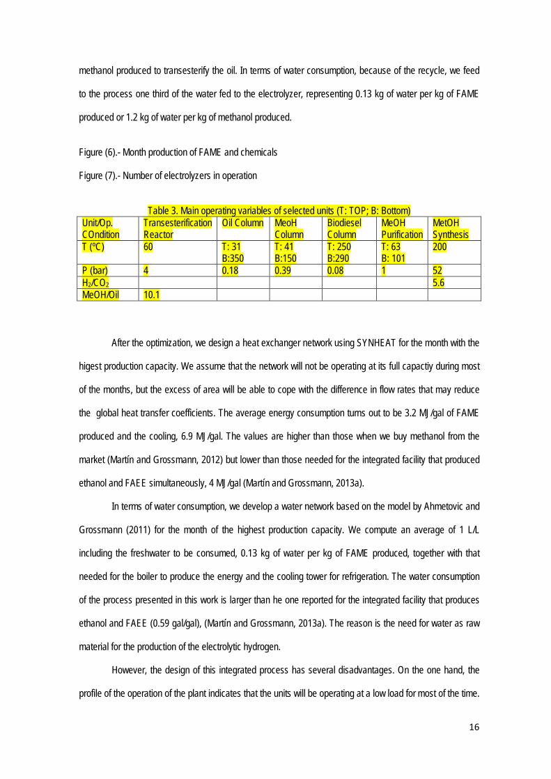
methanol produced to transesterify the oil. In terms of water consumption, because of the recycle, we feed
to the process one third of the water fed to the electrolyzer, representing 0.13 kg of water per kg of FAME
produced or 1.2 kg of water per kg of methanol produced.
Figure (6).- Month production of FAME and chemicals
Figure (7).- Number of electrolyzers in operation
Table 3. Main operating variables of selected units (T: TOP; B: Bottom) Unit/Op. COndition
Transesterification Reactor
Oil Column MeoH Column
Biodiesel Column
MeOH Purification
MetOH Synthesis
T (ºC) 60 T: 31 B:350
T: 41 B:150
T: 250 B:290
T: 63 B: 101
200
P (bar) 4 0.18 0.39 0.08 1 52 H2/CO2 5.6 MeOH/Oil 10.1
After the optimization, we design a heat exchanger network using SYNHEAT for the month with the
higest production capacity. We assume that the network will not be operating at its full capactiy during most
of the months, but the excess of area will be able to cope with the difference in flow rates that may reduce
the global heat transfer coefficients. The average energy consumption turns out to be 3.2 MJ/gal of FAME
produced and the cooling, 6.9 MJ/gal. The values are higher than those when we buy methanol from the
market (Martín and Grossmann, 2012) but lower than those needed for the integrated facility that produced
ethanol and FAEE simultaneously, 4 MJ/gal (Martín and Grossmann, 2013a).
In terms of water consumption, we develop a water network based on the model by Ahmetovic and
Grossmann (2011) for the month of the highest production capacity. We compute an average of 1 L/L
including the freshwater to be consumed, 0.13 kg of water per kg of FAME produced, together with that
needed for the boiler to produce the energy and the cooling tower for refrigeration. The water consumption
of the process presented in this work is larger than he one reported for the integrated facility that produces
ethanol and FAEE (0.59 gal/gal), (Martín and Grossmann, 2013a). The reason is the need for water as raw
material for the production of the electrolytic hydrogen.
However, the design of this integrated process has several disadvantages. On the one hand, the
profile of the operation of the plant indicates that the units will be operating at a low load for most of the time.

17
This can be addressed by integration of facilities into a complex. The second one is the large area needed.
For the operation of such a plant we require around 30 km2, although 0.5% corresponds to land while the
rest could be wastewater or saline water the area is large. Deserts can be an option from the solar
availability point of view, but the water requirement can be a problem.
We realize that when solar and wind energy are considered, their variability and uncertainty are to
be taken into account. However, as we have seen in Martín (2016), optimal operation is needed for the
development of surrogate models that will allow us to go into the operational level. From the conceptual
design point of view, monthly operation gives the big numbers in terms of units and operating conditions that
serves as first stage for a more detailed analysis.
4.2.-Economic evaluation
For the evaluation of the investment cost we use the factorial method (Sinnot, 1999). The Matche
web page (MATCHE, 2014) is used to estimate the cost of the chemical processing equipment, while
Goodrich et al (2012) is the reference for the solar panel cost and Saur (2008) for the electrolyzers. We size
the units for the month with the largest production capacity. The details for the units sizing as a function of
the flow rate or power can be found in the supplementary material of Almena and Martín, 2016]. Figure (8)
shows the share for the solar field and the rest of the equipment in the plant. 70% of the investment cost of
the equipment corresponds to the solar field, 25 % is due to the oil production, while the remaining 5% is
due to the chemical synthesis and product purification, including compressors, reactors, heat exchangers
and zeolite dehydration systems. The unit costs add up to 84 MM€.
Furthermore, the installed equipment represents 1.5 times the equipment cost except for the solar
field, which has its own installation cost (Goodrich et al 2012):
Investment= 1,300 €/kWp (18)
Piping, insulation, instrumentation and utilities represent 20%, 15%, 20% and 10% of the
equipment cost, except the wind turbines, respectively. The cost for the land and buildings is estimated to be
8.5 M€ for the chemical plant plus 5.5 €/m2 for the solar field (Maaben et al 2011). These items add up to
the fixed cost (111 M€). The fees represent 0.75% of the fixed cost. The direct costs is 112 M€. Including
the working capital, the investment adds up to 120M€.

18
Figure 8.- Investment cost
Furthermore, we estimate the production cost of the FAME. We consider the labour, taxes,
administration, utilities, equipment maintenance (Sinnot, 1999); see Figure 9 for the breakup of the cost.
We require an average of 6 MW of thermal energy (3.2 MJ/gal) and 13.7 MW of cooling. The cost adds up to
47 M€/yr for the production of 60 Mgal/yr, 0.79 €/gal, considering the credit from oxygen and glycerol at
0.02 €/kg and 0.3 €/kg, respectively, but having to pay for the fertilizers at 0.37€/kg.
Figure 9.- Production cost break down
Comparing this process with the one that simultaneously produces enthanol and biodiesel (FAEE),
the investment cost is similar 120 M€(160 M$) for solar methanol vs 180 M$ for the inetrgated multibiofuel
plant. However the production of bioethanol and biodiesel has a lower production cost, $0.35/gal with higher
enegy consumption (4MJ/gal) but lower water consumption (0.59 gal/gal) (Martín and Grossmann, 2013a)
5.-Conclusions
In this paper we have optimized an integrated facility to use renewable sources, solar and wind
energy, for the production of biodiesel, FAME. We obtain the oil from algae and the methanol from the
electrolysis of water and CO2 .
We formulate the problem as a multiperiod MINLP, where we simplify the optimization of the
operating conditions by considering a fix value for every month. Furthermore, we relax the integer variables
such as the number of ponds, panels, electrolyzers or wind turbines. We simultaneously optimize and heat
integrate the flowsheet to determine the optimal operating conditions of the units and over a year long
operation.
It turns out that the most efficient combination with no area limitations, is the use of solar panels to
provide the electricity needed for running the plant including the ponds. The advantage is that since we use
solar energy, the profile of the production of oil matches that of the methanol needs for the plant, and thus
the most expensive equipment, panels and ponds, are fully used the entire year. For a plant of 60 Mgal/yr of
biodiesel, the investment cost is 120 M€ and the production cost of biodiesel is 0.80€/gal.
6.-Nomeclature

19
a: Adjustable parameter for the power curve (m/s) Apannel (m2 /kWp) /8/ Algae -Prod: Flow of alga produced per s (kg/s) cpanel Investment per unit installed (€ / kWp ) carea Investment per unit installed (€ / m2 ) Csteam Steam cost (0.019 €/kg) Cat: Catalysis added to the transesterification reactor w/w Cp: Constant heat capacity (kJ/kg ºC) Costp : Cost of a pond 620 € per pond of 1000m2 Days(month): Days in a month effy (month): Relative Monthly production capacity versus the maximum one Ener_biom: Energy produced form the waste biomass (kW) fc(FAME)reference: Flow rate of FAME at the reference month (kg/s) Fi: Mass flow rate (kg/s) Growth: Growth velocity of algae (g/m2 day) Io: Solar Intensity (kWh/m2/d) k: Politropic coefficient. kp: Equilibrium constants m: Adjustable parameter for the power curve (m/s) MW Molecular weight (kg/kmol) Nelectrolizers: Number of electrolyzers npanel: Number of solar panels npond,reference: Number of ponds operating during the reference month. npond,total: Number of ponds bought nturbines: Number of wind turbines P: Power produced by a single turbine (kW) Pi : Partial pressure of component i (kPa) Ppanel Nominal power per panel /1kWp/ Pnominal Nominal Power of a turbine 1500 kW Op_cost_wind Rent of the ground for the turbines ( € /kWh) QSmax: Heat required in the integration ( kW) ratio_met: Molar ratio between methanol and oil Scale(month) Proportional coefficient of the maximum production capacity Solar_inc(month) :Monthly solar incidence (kWh per m2) T: Temperature (K) TTrans: Temperature at the transesterification reactor (ºC) time: seconds in a year (s) v: Wind velocity (m/s) vcut: Adjustable parameter for the power curve (m/s) W(unit): Electric power (kW) Windinvest Investment required per kW of wind power installed (€ / kW) yield: Conversion of the transesterification reactor Z: Objective function (€/s) η: Efficiency λ: Latent heat (kJ/kg) Units ( Legend for Figures9 Belt: Capillarity Belt Col: Column Compres: Compressor Deoxo: Deoxo Reactor HX: Heat Exchanger Electr: Electrolyzer Mix: Mixer Reactor: Reactor
20
Sep: Separator Scr: Source Snk: Sink Tank: Tank Zeo: Zeolites Sub Reference: Under the references conditions of flow capacity Acknowledgment
The authors acknowledge NSF Grant CBET0966524 and the CAPD industrial consortium. Dr. Martín also acknowledges the Salamanca Research founding for software licenses.
7.-References
Ahmetović, E., Grossmann, I.E., 2011. Global superstructure optimization for the design of integrated process water networks. AIChE J. 57 (2), 434-457 Almena, A., Martín, M., 2016. Techno-economic analysis of the production of epiclorhidrin from glycerol. Ind. Eng. Chem. Res. 55 (12), 3226-3238 Alwi, S.R.W., Rozali, N.E.M., Abdul-Manan, Z., Klemes, J.J., 2012. A process integration targeting method for hybrid power systems. Energy 2012; 44, 6-10 Archer, C.L., Jacobson, M.Z., 2004. Corrections to “Spatial and temporal distribution of U.S. winds and wind power at 80 m derived from measurements”, Journal of Geophysics. Research 2004; 109(D20116), doi:10.1020/2004JD005099, 2004. Archer, C.L., 2004 The Santa Cruz Eddy and U.S. wind power, Ph.D. Thesis, 190 pp., Stanford University, Stanford, 1 April 2004. Biegler, L.T., Grossmann, I.E., 1997. Westerberg AW. Systematic Methods of Chemical Process Design, New Jersey: Prentice Hall, 1997. Chinchen, G.C., Denny, R.J., Jennings, J.R., Spencer, M.S., Waugh, K.C., 1988. Synthesis of Methanol: part 1. Catalysts aid Kinetics Applied. Catalysis; 36, 1-65). CESR, 2006. Joint Emission trading as a socio-ecological transformation. http://www.usf.uni-kassel.de/cesr/index.php?option=com_project&task=view_detail&agid=25&lang=en Davis, W., Martín, M., 2014a. Optimal year-round operation for methane production from CO2 and Water using wind energy. Energy, 69, 497-505 Davis, W., Martín, M., 2014b Optimal year-round operation for methane production from CO2 and Water using wind and/or Solar energy. J. Cleaner Production 2014, 80, 252-261. Duran, M.A., Grossmann, I.E., 1986. Simultaneous optimization and heat integration of chemical processes. AIChE, J, 32, 123-138 Goodrich, A., James, T., Woodhouse, M., 2012. Residential, Commercial, and Utility-Scale Photovoltaic (PV) System Prices in the United States: Current Drivers and Cost-Reduction Opportunities NREL/TP-6A20-53347, February 2012. http://www.nrel.gov/docs/fy12osti/53347.pdf

21
IRENA.2012. Renewable Energy technologies: Cost Analysis Series. Vol. 1. Power Sector. Wind Power. 2012 Junta de Andalucía, 2014. Radiación Solar http://www.agenciaandaluzadelaenergia.es/Radiacion/radiacion2.php Levene, J.I., Mann, M.K., Margolis, R., Milbrandt, A., 2005. An Analysis of Hydrogen Production from Renewable Electricity Sources Conference Paper . NREL/CP-560-37612 September 2005 Maaßen, M., Rübsamen, M., Perez, A. 2011. Photovoltaic Solar Energy in Spain SEMINAR PAPERS IN INTERNATIONAL FINANCE AND ECONOMICS Seminar Paper 4/2011. Martín, M., 2016. Methodology for solar and wind based process design under uncertainty: Methanol production from CO2 and hydrogen Comp Chem Eng. 92, 43-54
Martín, M., Grossmann, I.E., 2012. Simultaneous optimization and heat integration for biodiesel production from cooking oil and algae. Ind. Eng. Chem. Res. 51 (23), 7998–8014 Martín, M., Grossmann, I.E., 2013a. Optimal engineered algae composition for the integrated simultaneous production of bioethanol and biodiesel AIChE J, 59 (8), 2872–2883 Martín, M., Grossmann, I.E., 2013b. ASI: Towards the optimal integrated production of biodiesel with internal recycling of methanol produced from glycerol. Environ. Prog. & Sust. Energ. 32(4), 791-801 Martín, M., Grossmann, I.E., 2013. On the systematic synthesis of sustainable biorefineries. Ind. Eng. Chem. Res., 52 (9), 3044-3064 Matche, 2014. http://www.matche.com/prod03.htm, 2014 (last accessed Feb. 2014). Montaigne, F., 2013. Record 400ppm CO2 milestone 'feels like we're moving into another era The Guardian Tuesday 14 May 2013 17.02 BS http://www.theguardian.com/environment/2013/may/14/record-400ppm-co2-carbon-emissions NEL (2012) http://www.nel-hydrogen.com/home/?pid=75 Last accessed November 2013 Pate, R. (2008) Biofuels and the Energy-Water Nexus AAAS/SWARM April 11, 2008 Albuquerque, NM. Park, J.B.K., Craggs, R.J., Shilton, A.N., 2011. Wastewater treatment high rate algal ponds for biofuel production. Biores. Technol. 2011; 102(1): .35-42. Sancho Ávila, J.M., Riesco Martín, J., Jiménez Alonso, C., Sánchez de Cos Escuin, M.C., Montero Cadalso, J., López Bartolomé, M. 2013. Atlas de radiación solar AEMET (Spain) Madrid. Spain 2013 www.aemet.es/documentos/es/serviciosclimaticos/datosclimatologicos/atlas_radiacion_solar/atlas_de_radiacion_24042012.pdf (last accessed January 2013) SAM, 2013. https://sam.nrel.gov/ Last Accessed February 2014 Saur, G. 2008. Wind-To-Hydrogen Project: Electrolyzer Capital Cost Study Technical Report NREL/TP-550-44103 , December 2008
Sazdanoff, N. 2006. Modeling and Simulation of the Algae to Biodiesel Fuel Cycle. Undegraduate Thesis. The Ohio State University, Columbus, OH, 2006.

22
Serrano, A., 2013. ¿Cuánto vale el Suelo?. http://www.fundacionsistema.com/(X(1)A(K8BoSNbrzgEkAAAAOTIzYWY5NTctNTIwYy00OTdiLTg3ZTgtM2Q2ZmZlM2VmMDBmwwOXljp7fDsqcz55OgITzcDhisU8qaQUWfOgX_mSKm41))/News/ItemDetail.aspx?id=4027&AspxAutoDetectCookieSupport=1 Last Accessed February 2014 Sinnot. R.K. 1999. Coulson and Richardson, Chemical Engineering. 3ªEd. Butterworth Heinemann, Singapore.
Tegen, S., Lantz, E., Hand, M., Maples, B., Smith, A., Schwabe, P., 2011. Cost of Wind Energy Review NREL/TP-5000-56266 March 2013 Trudewind, C.A., Schreiber, A., Haumann, D. 2014. Photocatalytic methanol and methane production using captured CO2 from coal power plants. Part I a Life Cycle Assessment. J. Clean. Prod. 70, 27-37 Trudewind, C.A., Schreiber, A., Haumann, D. 2014. Photocatalytic methanol and methane production using captured CO2 from coal power plants. Part II – Well-to-Wheel analysis on fuels for passenger transportation services . J. Clean. Prod. 2014, 70, 38-49 Van-Dal, E.S., Bouallou, C., 2013. Design and simulation of a methanol production plant from Co3 hydrogenation. J. Clean. Prod., 57, 38-45. Varbanov P, Klemes J., 2010. Total sites integrating renewables with extended heat transfer and recovery. Heat Transfer Engineering. 31(9), 733-41. Varvarezos, D.K., Grossmann, I.E., Biegler, L.T., 1992. An Outer Approximation Method for Multiperiod Design Optimization, Ind. Eng. Chem. Res., 31, 1466-1477. Varvarezos, D.K., Biegler, L.T., Grossmann, I.E., 1994. Multiperiod design optimization with SQP decomposition. Comp Chem. Eng., 18(7), 579-595. Walker, D.A., 2009. Biofuels, facts, fantasy, and feasibility. J. Appl.Phy., 21(5), 509-517. Wallas, S.M. Chemical Process Equipment: Selection and Design,3rd ed.; Butterworth-Heinemann: Oxford, UK, 1990.
http://windtrends.meteosimtruewind.com/wind_anomaly_maps.php?zone=EU Last accessed Dec 2014 Yee, T.F., Grossmann, I.E., 1990. Simultaneous optimization models for heat integration – II. Heat exchanger networks synthesis. Comp. Chem.l Eng. 1990; 28: 1165-1184.