OPTIMAL FUZZY GAIN SCHEDULING OF PID CONTROLLER · PDF filePID controller. Keywords: Fuzzy...
16
International Journal of Innovative Computing, Information and Control ICIC International c 2013 ISSN 1349-4198 Volume 9, Number 2, February 2013 pp. 651–666 OPTIMAL FUZZY GAIN SCHEDULING OF PID CONTROLLER OF SUPERCONDUCTING MAGNETIC ENERGY STORAGE FOR POWER SYSTEM STABILIZATION Theerawut Chaiyatham and Issarachai Ngamroo School of Electrical Engineering Faculty of Engineering King Mongkut’s Institute of Technology Ladkrabang Chalongkrung Road, Ladkrabang, Bangkok 10520, Thailand [email protected] Received October 2011; revised February 2012 Abstract. It is well known that the proportional-integral-derivative (PID) can be ap- plied to solve practical control problems effectively. However, in the face of the high system nonlinearity, the PID controller with fixed parameters may fail to provide satis- factory control performance. To enhance the PID control effect, a new design of the fuzzy gain scheduling of PID controller (FGS-PID) is presented in this paper. The proposed technique is applied to design FGS-PID controllers of superconducting magnetic energy storage (SMES) for power system stabilization. Without trial and error, the scale fac- tors, membership functions and control rules of the FGS-PID controller are automatically tuned by a bee colony optimization. With the optimal FGS-PID controller, the PID pa- rameters can be adjusted automatically according to various system operating conditions. As a result, the high robustness of the FGS-PID controller can be expected. Simulation study confirms that the stabilizing effect and robustness of the proposed SMES with an optimal FGS-PID controller are much superior to those of the SMES with an optimal PID controller. Keywords: Fuzzy gain scheduling, PID controller, Power system stabilization, Super- conducting magnetic energy storage, Bee colony optimization 1. Introduction. With the development of power systems around the world, the con- struction of extensive interconnected lines among different power systems has considerably increased. The interconnection of power systems not only provides the high system reli- ability, but also increases the economical merits significantly. Nevertheless, the increase in interconnected power systems has brought a low frequency inter-area oscillation with poor damping [1]. The inter-area oscillation may cause the system instability and com- plete blackout eventually. To damp out the inter-area oscillations, several devices have been applied in previous works such as power system stabilizer [2], thyristor controlled series capacitor [3] and static var compensator [4]. Among the stabilizing devices, the superconducting magnetic energy storage (SMES) which can rapidly supply/absorb electrical power to/from the power systems, is expected as the smart stabilizing device [5]. The simultaneous active and reactive power controls of SMES can be applied as a channel to mitigate the problem of inter-area oscillations due to undesirable disturbances. In [6], the robust damping controller design of SMES based on a weight and normalized eigenvalue-distance minimization method has been presented. In [7], a linear matrix inequality approach to robust damping control design in power systems with SMES has been proposed. In [8], the SMES controller based on H ∞ loop shaping control has been applied to stabilize system frequency oscillation. In 651
Transcript of OPTIMAL FUZZY GAIN SCHEDULING OF PID CONTROLLER · PDF filePID controller. Keywords: Fuzzy...

International Journal of InnovativeComputing, Information and Control ICIC International c©2013 ISSN 1349-4198Volume 9, Number 2, February 2013 pp. 651–666
OPTIMAL FUZZY GAIN SCHEDULING OF PID CONTROLLEROF SUPERCONDUCTING MAGNETIC ENERGY STORAGE
FOR POWER SYSTEM STABILIZATION
Theerawut Chaiyatham and Issarachai Ngamroo
School of Electrical EngineeringFaculty of Engineering
King Mongkut’s Institute of Technology LadkrabangChalongkrung Road, Ladkrabang, Bangkok 10520, Thailand
Received October 2011; revised February 2012
Abstract. It is well known that the proportional-integral-derivative (PID) can be ap-plied to solve practical control problems effectively. However, in the face of the highsystem nonlinearity, the PID controller with fixed parameters may fail to provide satis-factory control performance. To enhance the PID control effect, a new design of the fuzzygain scheduling of PID controller (FGS-PID) is presented in this paper. The proposedtechnique is applied to design FGS-PID controllers of superconducting magnetic energystorage (SMES) for power system stabilization. Without trial and error, the scale fac-tors, membership functions and control rules of the FGS-PID controller are automaticallytuned by a bee colony optimization. With the optimal FGS-PID controller, the PID pa-rameters can be adjusted automatically according to various system operating conditions.As a result, the high robustness of the FGS-PID controller can be expected. Simulationstudy confirms that the stabilizing effect and robustness of the proposed SMES with anoptimal FGS-PID controller are much superior to those of the SMES with an optimalPID controller.Keywords: Fuzzy gain scheduling, PID controller, Power system stabilization, Super-conducting magnetic energy storage, Bee colony optimization
1. Introduction. With the development of power systems around the world, the con-struction of extensive interconnected lines among different power systems has considerablyincreased. The interconnection of power systems not only provides the high system reli-ability, but also increases the economical merits significantly. Nevertheless, the increasein interconnected power systems has brought a low frequency inter-area oscillation withpoor damping [1]. The inter-area oscillation may cause the system instability and com-plete blackout eventually. To damp out the inter-area oscillations, several devices havebeen applied in previous works such as power system stabilizer [2], thyristor controlledseries capacitor [3] and static var compensator [4].
Among the stabilizing devices, the superconducting magnetic energy storage (SMES)which can rapidly supply/absorb electrical power to/from the power systems, is expectedas the smart stabilizing device [5]. The simultaneous active and reactive power controlsof SMES can be applied as a channel to mitigate the problem of inter-area oscillationsdue to undesirable disturbances. In [6], the robust damping controller design of SMESbased on a weight and normalized eigenvalue-distance minimization method has beenpresented. In [7], a linear matrix inequality approach to robust damping control designin power systems with SMES has been proposed. In [8], the SMES controller based onH∞ loop shaping control has been applied to stabilize system frequency oscillation. In
651

652 T. CHAIYATHAM AND I. NGAMROO
[9], the robust SMES controller based on H∞ loop shaping control has been proposed tostabilize the inter-area oscillation. In [10], a robust mixed H2/H∞ control for frequencystabilization of an interconnected power system including SMES has been studied. In [11],the robust pole placement design of SMES controller for damping inter-area oscillationshas been presented. Even the SMES controllers proposed in [6-11] are able to solve theproblem of inter-area oscillation successfully, the structure of these SMES controllers iscomplex with high order which is not easy to implement in practical systems.Generally, the most popular controller used in industrial systems is the proportional-
integral-derivative (PID) controller because it has a simple structure and a high abilityof solving many practical control problems [12,13]. The utilizations of PID controllerhave been proposed in many research works. In [14], a new design of a performance-adaptive PID controller with model prediction structure has been proposed. An optimalPID controller design for a class of PWM feedback time-varying systems by fusing theorthogonal-functions approach and the genetic algorithm has been studied in [15]. A PIDcontroller plus a novel linear-to-nonlinear translator has been proposed and applied toimprove the operating performance of the boost converter [16]. A unified PID tuningmethod for load frequency control of power systems has been discussed in [17]. However,under the high nonlinearity of the system, a PID controller with fixed parameters mayno longer provide satisfactory control performance, since the PID parameters should beadjusted following a change of input signal [18].To enhance the control performance of the PID controller against high system nonlin-
earity, the application of knowledge systems such as fuzzy control [19-21] and fuzzy gainscheduling control [22] has been proposed. There are many previous research works whichhave applied the fuzzy gain scheduling control to improve the controller performance byvarying the control parameters according to the input signal. In [23], a fuzzy applicationto load-frequency control using fuzzy gain scheduling of PI controllers has been proposed.In [24], a fuzzy gain scheduling PI controller has been applied to an interconnected elec-trical power system. In [25], an application of fuzzy gain-scheduling proportional-integralcontrol has been proposed to improve engine power and speed behavior in a hybrid elec-tric vehicle. In [26], a fuzzy gain scheduling integral and derivative controller has beenapplied to automatic generation control of power system. It seems that these works canshow the effectiveness of fuzzy gain scheduling to improve the controller. Nevertheless,these papers have been proposed without considering the optimal design of the fuzzyparameters although the selection of scale factors (SF), membership functions (MF) andcontrol rules (CR) of the fuzzy gain scheduling is very important procedure.To overcome this problem, this paper presents a new design of optimal fuzzy gain
scheduling of PID (FGS-PID) controller for the SMES to stabilize the power systemoscillation. To achieve the optimal SFs, MFs and CRs of the FGS-PID controller, abee colony optimization (BCO) [27] is applied. Simulation study is carried out in thenonlinear model of a two-area four-machine interconnected power system. The proposedSMES with an optimal FGS-PID controller not only shows superior damping effect to theSMES with an optimal PID controller, but also provides high robustness under variousoperating conditions and large disturbances.
2. Study Power System and SMES Model. A two-area four-machine interconnectedpower system [1] in Figure 1 is used as the study system. Two areas are connected by anAC tie-line which exhibits a weak inter-area oscillation. Each area has two generators,i.e., G1 and G2 in area 1, and G3 and G4 in area 2. Each generator is represented bythe fourth-order model and is equipped with a simplified exciter and governor [1]. For

OPTIMAL FGS-PID CONTROLLER OF SMES 653
Figure 1. Two-area interconnected power system with SMES
Figure 2. SMES model with active and reactive controllers
the study purpose, the active power (PT12) is transferred from areas 1 to 2. Based on theresidue method [7], the suitable location of SMES is selected at bus 120 in area 2.
The SMES model with active and reactive power modulation control scheme, as de-picted in Figure 2, is used here [28]. In particular, the SMES unit includes active power(P) controller (KPsm(s)) and reactive power (Q) controllers (KQsm(s)). The active andreactive power flow deviations from bus 120 to bus 13 (∆Ptie(120−13) and ∆Qtie(120−13)) areused as the feedback input signals for the SMES controller.
The effect of SMES coil current (IDC) is also included in this model, since the dynamicbehaviour of IDC affects the overall performance of SMES. In practice, IDC is not allowedto reach zero to prevent the possibility of discontinuous conduction under unexpecteddisturbances. On the other hand, IDC which is above the maximum allowable limit maylead to the loss of superconducting properties. On the basis of the hardware operationalconstraints, the lower and upper coil current limits are considered and assigned as 0.30IDC0
and 1.38IDC0, respectively [28], where IDC0 is an initial value of IDC . In addition, thecoil current controller KIsm(s) in Figure 2 which is a proportional-integral controller, isused for stabilizing the SMES coil current. Here, IDC can be calculated from the Power-Energy-Current (PEI) block which has a relation as
IDC =√I2DC0 − 2Eout/(LsmI2sm,base) (1)
Eout =
∫Psmdt.Ssm,base (2)
where Eout is the SMES energy output (J), Lsm is the SMES coil inductance (H), Ism,base
is the SMES current base (A) and Ssm,base is the SMES MVA base (MVA). Subsequently,

654 T. CHAIYATHAM AND I. NGAMROO
the energy stored in an SMES unit (Esm) and the initial energy stored (Esm0) can bedetermined by
Esm = Esm0 − Eout (3)
Esm0 = 0.5LsmI2sm0I
2sm,base. (4)
The desired active (Pd) and reactive (Qd) power outputs of SMES can be expressed as
Pd = VtsIDCAP (5)
Qd = VtsIDCAQ (6)
where AP and AQ are the active and reactive power fractions, respectively, and Vts isa terminal bus voltage of SMES unit (pu). The SMES active (Psm) and reactive (Qsm)power outputs are the output of the SMES controlled converter (CONV). The convertertransfer function can be represented by the first-order time-lag compensator as
CONV = 1/(1 + 0.01s) (7)
Here, KPsm(s) and KQsm(s) are designed based on the proposed FGS-PID control.
3. Proposed FGS-PID Controller. It is well known that a PID controller is the mostwidely used in modern industry due to its simple control structure and easy design. Theclassical PID controller can be expressed in the time domain as
uPID(t) = KP e(t) +KI
∫e(t)dt+KD
de(t)
dt(8)
where e is the input control signal of controller, uPID(t) is the control signal for the system,and KP , KI and KD are the proportional, integral and derivative gains, respectively.However, the classical PID controller does not yield reasonable performance over a wide
range of operating conditions because of the fixed PID gains. This is the reason to usethe fuzzy logic to tune the parameters of PID controller.From (8), three coefficients KP , KI and KD are tuned by using knowledge base and
fuzzy interface of fuzzy gain scheduler, then the classical PID controller generates thecontrol signal. The proposed FGS-PID controller scheme can be shown in Figure 3.
Figure 3. Schematic of FGS-PID controller
Through fuzzy knowledge, the online self-tuning PID parameters of FGS-PID controllercan be established by the following equations
KP = KPC .KPF (9)
KI = KIC .KIF (10)
KD = KDC .KDF (11)
where KPC , KIC and KDC are the proportional, integral and derivative gains of theclassical PID controller, respectively. These PID gains are optimally tuned. KPF , KIF
and KDF are the proportional, integral and derivative gains, respectively. These gains areobtained from the online tuning of fuzzy gain scheduler.

OPTIMAL FGS-PID CONTROLLER OF SMES 655
From (9), (10) and (11), KP , KI and KD are online tuned based on the current absoluteerror (|E|) and the current absolute derivative error (|E ′|) by a fuzzy gain scheduler asshown in Figure 4. Note that the fuzzy gain scheduler has two inputs and three outputs.For the part of input, E and E ′ are given by
E = eKS1 (12)
E ′ = e′KS2 (13)
where KS1 and KS2 are the SF of fuzzy gain scheduler.
Figure 4. Block diagram of fuzzy gain scheduler
Here, the fuzzy gain schedule is based on the fuzzy singleton. The CRs of fuzzy gainscheduler are in the form of
If input1 is F and input2 is G, then KPF = H, KIF = I, KDF = J (14)
where F, G, H, I and J are the fuzzy set on the corresponding supporting sets. The MFsof these fuzzy sets for input and output are shown in Figure 5. The MFs for input1 andinput2 as indicated in Figure 5(a), each input consists of three triangular membershipsand one trapezoidal membership. Each output of the fuzzy gain scheduler includes threeconstant memberships that are S, M and L. From Figure 5, Z is zero, S is small, M ismedium and L is large.
In case of the design of FGS-PID controller, there are two tuning parameters of SF, i.e.,KS1 andKS2. Besides, there are many tuning parameters of MFs and CRs. Here, considertwo shapes of an input MF, i.e., triangular and trapezoidal memberships which are shownin Figure 6. A triangular membership is defined by three parameters, i.e., left base(L), center (C), and right base (R). For a trapezoidal membership, it is defined by fourparameters, i.e., left base (L), center 1 (C1), center 2 (C2), and right base (R). Each inputMF is composed of one trapezoidal membership and three triangular memberships. Eachoutput MF includes three constant memberships. Accordingly, it has thirteen parametersfor input and three parameters for output. One FGS-PID controller has two inputs andthree outputs. Therefore, there are thirty five tuning parameters (13× 2 + 3× 3 = 35).
The CRs for two-inputs and one-output fuzzy logic controller, is represented by n rowsand five columns matrix as shown in Figure 7. When this idea is applied to the fuzzy logictoolbox, n is the total number of relationships between all possible input pairs (for 4 MFs,n = 42 = 16). The third-fifth columns in the control rule table are the linguistic variableoutputs. Generally, it is represented by a numeric symbol. The universe of discourse inthis study contains seven memberships. Consequently, the control rules are representedby four numbers (1 to 4), 1: Z, 2: S, 3: M and 4: L. Note that there are sixteen tuningparameters. Hence, the total parameters for two inputs and three outputs of FGS-PIDcontroller are fifty three (2 + 35 + 16 = 53).
In the FGS-PID controller design, the important procedure is how to determine theSFs, MFs and CRs. In general, they are determined by trial and error and designer’sexperiences. To solve this problem, this study applies a BCO algorithm to automaticallydetermine the SFs, MFs and CRs.

656 T. CHAIYATHAM AND I. NGAMROO
(a) Input (b) Output
Figure 5. Membership functions for input and output of FGS
Figure 6. The shape of input membership functions
Figure 7. Structure of control rules for FGS-PID
The motivation of the practical use of the theoretic results of proposed method isthe automatic optimization of SFs, MFs and CRs for the FGS-PID controller by BCO.Without trial and error and designer’s experience, the optimal FGS-PID controller canbe achieved. In addition, the proposed method can be practically applied in industries orpower systems such as a self-learning support system for pupils based on a fuzzy scheme[29]. The application of proposed method to these practical systems not only considerablysimplifies the control design process, but also significantly enhances the control effect ofthe system.The novel and significant contribution of proposed BCO based FGS-PID controller of
SMES for power system stabilization are given as follows.

OPTIMAL FGS-PID CONTROLLER OF SMES 657
1) The proposed FGS-PID controller is very effective and robust because the FGS-PIDcan deal with intrinsic uncertainties by changing controller parameters. The effectivenessand robustness of the proposed FGS-PID controller have been shown in simulation study.
2) Without trial and error, all adjusting parameters of the FGS-PID controller, i.e.,SFs, MFs and CRs are automatically optimized by a BCO.
The optimization problem for the optimal FGS-PID controller is formulated basedon the minimization of integral absolute error (IAE) of the speed difference betweengenerators G1 and G3 (∆ωd) which implies the inter-area oscillation as,
Minimize IAE =
t∫0
|∆ωd| dt (15)
This optimization problem is solved by the BCO.
4. Bee Colony Optimization. The BCO algorithm mimics the food foraging behaviourof swarms of honey bees [27]. Honey bees use several mechanisms like waggle dance tooptimally locate food sources and to search new ones. This makes them a good candidatefor developing new intelligent search algorithms. It is a very simple, robust and populationbased stochastic optimization algorithm. The procedure of the BCO algorithm for tuningFGS-PID parameters as shown in Figure 8 can be described as below:
Figure 8. Procedure of BCO algorithm for tuning FGS-PID parameters

658 T. CHAIYATHAM AND I. NGAMROO
Step 1: Generate randomly the initial populations of n scout bees for the parametersof SF, MF and CR. These initial populations must be feasible candidate solutions thatsatisfy the constraints. Set NC = 0.Step 2: Represent the value of SF, MF and CR from each population.Step 3: Evaluate the fitness value of the initial populations by (15).Step 4: Select m best sites for neighbourhood search. Separate the m best sites to two
groups, the first group has e best sites and another group has m− e best sites.Step 5: Determine the size of neighbourhood search of each best size (patch size, ngh).Step 6: Recruit bees of ne employed bees for selected sites (more bees for the best e
sites).Step 7: Represent the value of SF, MF and CR from each employed bee.Step 8: Select the fittest bees from each patch.Step 9: Check the stopping criterion. If satisfied, terminate the search, else NC =
NC + 1.Step 10: Assign the n−m remaining bees to random search. Go to Step 2.
where ns is the number of scout bee, NC is the number of iteration, m is the numberof sites selected for neighbourhood search, e is the number of best “elite” sites out of mselected sites and ne is the number of employed bee.
5. Simulation Study. The stabilizing effect of the SMES with an optimal FGS-PIDcontroller is compared with the SMES with an optimal PID controller. Both controllersare optimized based on the same objective function (15) and the operating condition incase 1 as shown in Table 1. The constant parameters of BCO are set as: ns = 100,ne = 20, m = 10, e = 5, ngh = 20% and NC = 100.As a result, the convergence curves of the SMES with the optimal PID controller and
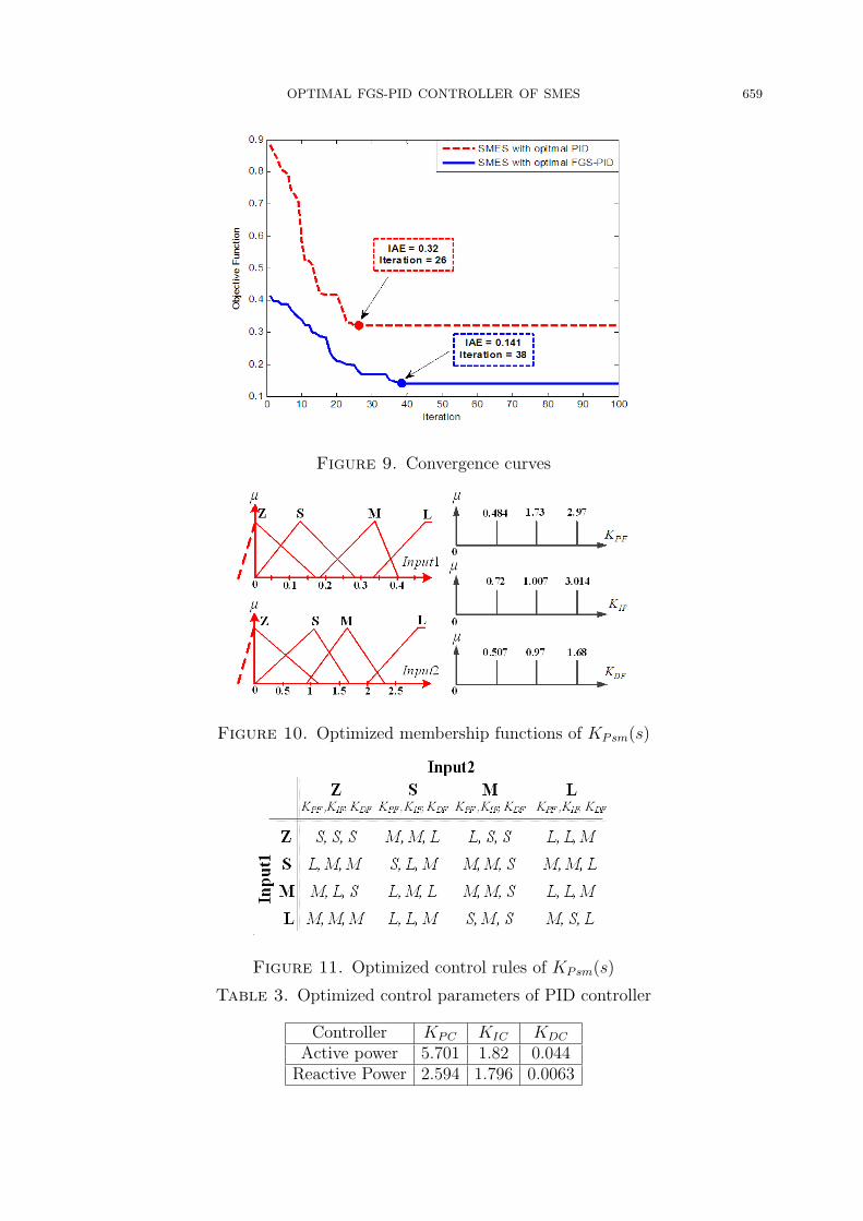
the SMES with the optimal FGS-PID controller are depicted in Figure 9. They start atthe different initial values and gradually decrease to the minimum values.The optimized parameters of KPsm(s) and KQsm(s) of SMES with optimal FGS-PID
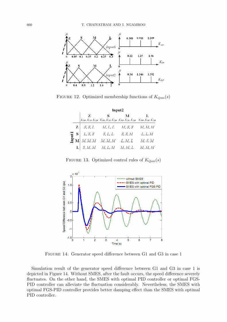
controller are given in Table 2. Besides, the MFs and CRs of KPsm(s) and KQsm(s) areshown in Figures 10 and 11 and Figures 12 and 13, respectively. For the compared optimalPID controller, the optimized parameters are given in Table 3.Nonlinear simulations are carried out for four case studies in Table 1.
Table 1. Operating conditions and disturbances
Case Applied DisturbanceInitial value of
PT12 (pu)
1Temporary 3 phases fault occurs at bus 13 for 70 ms andis cleared naturally.
3.0
2Temporary 3 phases fault occurs on one line between bus3 and 101 for 70 ms and is cleared naturally.
2.0
3 Loss of one line between bus 101 and 13 at t = 0.5 s 4.0
4Temporary 3 phases fault occurs at bus 13 for 100ms andis cleared naturally.
vary from 2.5to 4.5
Table 2. Optimized control parameters of FGS-PID controller
Controller KS1 KS2 MF CRKPsm(s) 0.886 0.932 Figure 8 Figure 9KQsm(s) 1.245 1.043 Figure 10 Figure 11
OPTIMAL FGS-PID CONTROLLER OF SMES 659
Figure 9. Convergence curves
Figure 10. Optimized membership functions of KPsm(s)
Figure 11. Optimized control rules of KPsm(s)
Table 3. Optimized control parameters of PID controller
Controller KPC KIC KDC
Active power 5.701 1.82 0.044Reactive Power 2.594 1.796 0.0063
660 T. CHAIYATHAM AND I. NGAMROO
Figure 12. Optimized membership functions of KQsm(s)
Figure 13. Optimized control rules of KQsm(s)
Figure 14. Generator speed difference between G1 and G3 in case 1
Simulation result of the generator speed difference between G1 and G3 in case 1 isdepicted in Figure 14. Without SMES, after the fault occurs, the speed difference severelyfluctuates. On the other hand, the SMES with optimal PID controller or optimal FGS-PID controller can alleviate the fluctuation considerably. Nevertheless, the SMES withoptimal FGS-PID controller provides better damping effect than the SMES with optimalPID controller.

OPTIMAL FGS-PID CONTROLLER OF SMES 661
(a) Active power output of SMES
(b) Coil current of SMES
Figure 15. Active power output and coil current of SMES in case 1
Figure 16. Generator speed difference between G1 and G3 in case 2

662 T. CHAIYATHAM AND I. NGAMROO
(a) Active power output of SMES
(b) Coil current of SMES
Figure 17. Active power output and coil current of SMES in case 2
The active power output and the coil current of SMES are demonstrated in Figures15(a) and 15(b), respectively. It can be observed that the fluctuation of active poweroutput and coil current of the SMES with optimal FGS-PID controller is higher thanthat of the EZ with optimal PID controller. Accordingly, the generator speed differencebetween G1 and G3 in case of the EZ with optimal FGS-PID controller are lower thanthat of the SMES with optimal PID controller.For case 2, simulation results are shown in Figures 16 and 17. In comparison to the
SMES with optimal PID controller, the SMES with optimal FGS-PID controller showsbetter stabilizing effect.For case 3, simulation results are shown in Figures 18 and 19. The SMES with optimal
PID controller completely loses stabilizing effect. The system becomes unstable same asthe without SMES case. On the contrary, the proposed SMES with optimal FGS-PIDcontroller can tolerate this severe disturbance. It is able to damp out power oscillationsrobustly. The active power output and coil current of SMES are demonstrated in Figures18 (a) and (b), respectively.

OPTIMAL FGS-PID CONTROLLER OF SMES 663
Figure 18. Generator speed difference between G1 and G3 in case 3
(a) Active power output of SMES
(b) Coil current of SMES
Figure 19. Active power output and coil current of SMES in case 3

664 T. CHAIYATHAM AND I. NGAMROO
Figure 20. Integral absolute error of ∆ωd in case 4
In case 4, the initial tie-line power flow is varied under the occurrence of fault. Thevariation of IAE of the generator speed difference between G1 and G3 is shown in Figure20. When the power flow increases, the IAE in case of without SMES and the SMESwith optimal PID controller extremely increase. Eventually, the system becomes unstablewhen the initial tie-line power flow is at 4.5 pu. On the other hand, the IAE in caseof SMES with optimal FGS-PID controller increases slightly. These results confirm thatthe superior robustness of the proposed SMES with optimal FGS-PID controller over theSMES with optimal PID controller against the heavy power flow.
6. Conclusion. The optimal fuzzy gain scheduling of the online self-tuning PID con-troller design for the SMES has been proposed for power system stabilization. The studyresults can be summarized as follows:
1) Without trial and error and designer’s experience, the scale factors, membership func-tions and control rules of the optimal FGS-PID controller are automatically tuned bythe BCO.
2) With the FLS-PID, the robustness of the PID controller against various system uncer-tainties and disturbances can be significantly improved since the PID parameters canbe automatically tuned by the FGS according to the system operating conditions.
Simulation results confirm that the proposed SMES with an optimal FGS-PID controlleris much superior to that of SMES with optimal PID controller in terms of stabilizing effectand robustness against severe faults and heavy power flow.
Acknowledgment. This work was supported by the King Mongkut’s Institute of Tech-nology Ladkrabang Research Fund.
REFERENCES
[1] P. Kundur, Power System Stability and Control, McGraw-Hill, 1994.[2] J. Pahasa and I. Ngamroo, Least square support vector machine for power system stabilizer design
using wide area phasor measurements, International Journal of Innovative Computing, Informationand Control, vol.7, no.8, pp.4487-4501, 2011.

OPTIMAL FGS-PID CONTROLLER OF SMES 665
[3] Z. Cai, L. Zhu, Z. Lan, D. Gan, Y. Ni, L. Shi and T. Bi, A study on robust adaptive modulationcontroller for TCSC based on COI signal in interconnected power systems, Electrical Power SystemsResearch, vol.78, no.1, pp.147-157, 2008.
[4] X. Y. Bian, C. T. Tse, J. F. Zhang and K. W. Wang, Coordinated design of probabilistic PSS andSVC damping controllers, International Journal of Electrical Power and Energy Systems, vol.33,no.3, pp.445-452, 2011.
[5] I. Ngamroo, Simultaneous optimization of SMES coil size and control parameters for robust powersystem stabilization, IEEE Trans. on Applied Superconductivity, vol.21, no.3, pp.1358-1361, 2011.
[6] B. C. Pal, A. H. Coonick and D. C. Macdonald, Robust damping controller design in power systemwith superconducting magnetic energy storage devices, IEEE Trans. on Power Systems, vol.15, no.1,pp.320-325, 2000.
[7] B. C. Pal, A. H. Coonick, I. M. Jaimoukha and H. El-zobaidi, A linear matrix inequality approachto robust damping control design in power systems with superconducting magnetic energy storagedevice, IEEE Trans. on Power Systems, vol.15, no.1, pp.356-362, 2000.
[8] I. Ngamroo, C. Taeratanachai, S. Dechanupaprittha and Y. Mitani, Enhancement of load frequencystabilization effect of superconducting magnetic energy storage by static synchronous series com-pensator based on H8 control, Energy Conversion and Management, vol.48, no.4, pp.1302-1312,2007.
[9] A. H. M. A. Rahim and E. P. Nowicki, A robust damping controller for SMES using loop-shapingtechnique, International Journal of Electrical Power & Energy Systems, vol.27, no.5-6, pp.465-471,2007.
[10] H. Shayeghi, A. Jalili and H. A. Shayanfar, A robust mixed H2/H∞ based LFC of a deregulatedpower system including SMES, Energy Conversion and Management, vol.49, no.10, pp.2656-2668,2008.
[11] B. C. Pal, Robust pole placement versus root-locus approach in the context of damping interareaoscillations in power systems, IEE Proc. Generation, Transmission and Distribution, vol.149, no.6,pp.739-745, 2002.
[12] E. A. Gargari, R. Rajabioun, F. Hashemzadeh and F. R. Salmasi, A decentralized PID controllerbased on optimal shrinkage of Gershgorin bands and PID tuning using colonial competitive algorithm,International Journal of Innovative Computing, Information and Control, vol.5, no.10(A), pp.3227-3240, 2009.
[13] T. Hagiwara, K. Yamada, I. Murakami, Y. Ando and T. Sakanushi, A design method for robuststabilizing modified PID controllers for time-delay plants with uncertainty, International Journal ofInnovative Computing, Information and Control, vol.5, no.10(B), pp.3553-3563, 2009.
[14] H. Yagi, J. Shimonishi, T. Yamamoto and T. Hinamoto, Design of a performance-adaptive PIDcontroller with a model prediction structure, International Journal of Innovative Computing, Infor-mation and Control, vol.5, no.10(A), pp.2969-2983, 2009.
[15] C.-H. Hsieh, W.-H. Ho and J.-H. Chou, Optimal PID controllers design of PWM feedback time-varying systems using orthogonal-functions approach and genetic algorithm, International Journalof Innovative Computing, Information and Control, vol.5, no.2, pp.387-397, 2009.
[16] K. I. Hwu and Y. T. Yau, Performance enhancement of boost converter based on PID controller pluslinear-to-nonlinear translator, IEEE Trans. on Power Electronics, vol.25, no.5, pp.1351-1361, 2010.
[17] W. Tan, Unified tuning of PID load frequency controller for power systems via IMC, IEEE Trans.on Power Systems, vol.25, no.1, pp.341-350, 2010.
[18] M. Santos and A. L. Dexter, Control of a cryogenic process using a fuzzy PID scheduler, ControlEngineering Practice, vol.10, no.10, pp.1147-1152, 2002.
[19] N. W. Aung, E. W. Cooper, Y. Hoshino and K. Kamei, A proposal of fuzzy control systems for trailersdriven by multiple motors in side slipways to haul out ships, International Journal of InnovativeComputing, Information and Control, vol.3, no.4, pp.799-812, 2007.
[20] M. Wang, B. Chen and S. Tong, Adaptive fuzzy tracking control for strict-feedback nonlinear systemswith unknown time delays, International Journal of Innovative Computing, Information and Control,vol.4, no.4, pp.829-837, 2008.
[21] L. Luoh, Control design of T-S fuzzy large-scale systems, International Journal of Innovative Com-puting, Information and Control, vol.5, no.9, pp.2869-2880, 2009.
[22] K. J. Astrom and B. Wittenmark, Adaptive Control, Addison-Wesley, Publishing Company, 1989.[23] E. Cam and I. Kocaarslan, Load frequency control in two area power systems using fuzzy logic
controller, Energy Conversion and Management, vol.46, no.2, pp.233-243, 2005.

666 T. CHAIYATHAM AND I. NGAMROO
[24] E. Cam and I. Kocaarslan, A fuzzy gain scheduling PI controller application for an interconnectedelectrical power system, Electric Power Systems Research, vol.73, no.3, pp.267-274, 2005.
[25] F. U. Syed, M. L. Kuang, M. Smith, S. Okubo and H. Ying, Fuzzy gain-scheduling proportional-integral control for improving engine power and speed behavior in a hybrid electric vehicle, IEEETrans. on Vehicular Technology, vol.58, no.1, pp.69-84, 2009.
[26] L. H. Hassan, H. A. F. Mohamed, M. Moghavvemi and S. S. Yang, Automatic generation control ofpower system with fuzzy gain scheduling integral and derivative controllers, International Journalof Power Energy and Artificial Intelligence, vol.1, no.1, pp.29-33, 2008.
[27] D. Karaboga, An idea based on honey bee swarm for numerical optimization, Technical Report-Tr06t,Erciyes Univ., Turkey, 2005.
[28] S. Dechanupaprittha, K. Hongesombut, M. Watanabe, Y. Mitani and I. Ngamroo, Stabilization oftie-line power flow by robust SMES controller for interconnected power system with wind farms,IEEE Trans. on Applied Superconductivity, vol.17, no.2, pp.2365-2368, 2007.
[29] K. Eguchi, S. Kurebayashi, H. Zhu, T. Inoue and F. Ueno, A self-learning support system for pupilsbased on a fuzzy scheme, International Journal of Innovative Computing, Information and Control,vol.4, no.10, pp.2441-2450, 2008.