
Optimal Design of PM Synchronous Generator for Aerial ... · Figure 1 shows the generator position,...
20
* Corresponding author E-mail address: [email protected] Int. J. Research in Industrial Engineering, pp. 49-68 Volume 3, Number 3, 2014 International Journal of Research in Industrial Engineering www.nvlscience.com Optimal Design of PM Synchronous Generator for Aerial Industries Power Supply Using Cuckoo Algorithm A. Nikbakhsh * , S. A. Gholamian, S. M. Hoseini Department of Electrical and Computer Engineering, Babol University of Technology, Babol, Iran A B S T R A C T A R T I C L E I N F O The Generators used in aerial industries should have the characteristics such as high efficiency, power density and reliability, low weight and volume. Among different generators, permanent magnet synchronous generator adequately satisfied these requirements. In this paper, first the dimensions and other quantities of this generator are calculated through an analytical model. Then using Cuckoo Optimization Algorithm (COA), these quantities are optimized to suit for desirable needs of aerospace systems, in order that the total volume of the generator could be minimized and its efficiency could be maximized. The results of this design for the permanent magnet synchronous generator application in aerospace systems have been satisfactory. Article history : Received: June 18, 2014 Revised: Aug 20, 2014 Accepted: September 21, 2014 Keywords : Cuckoo Algorithm, Optimization, Permanent Magnet, Synchronous generator, Aerial Industries. 1. Introduction The use of electric power in the aerial industry has being increase in recent years. As the electrical power supply of aerospace system, generators are needed for the power supply of the various parts i.e. the fuel system with electric motor driven pumps, wing anti-ice electric system, exterior and interior lighting equipment and controller motors in wings of aircraft, rockets and missiles. In wings controlling of aircraft, missiles and aerospace systems, hydraulic actuators are replaced by electrical and electromechanical actuators. Generators used in aerospace systems, are installed at the end of the engine and they provide required electrical energy of its different parts. Figure 1 shows the generator position, inside the aerospace system engine [1-6]. Electrical systems in aircraft are used for the production, regulation, and distribution of electricity throughout the plane. Plane electrical systems work by means of different levels of AC and DC electric voltages. In this typical system 115/200V AC, 400 Hz and 28 volt DC voltages are used. Some different sources of electrical power supply in large aircraft are shown in Figure 2 which includes: 1.The main generator 2.Auxiliary power unit (APU); 3. Ram air turbine (RAT); 4.External power source; For example, the ground power unit (GPU) [6].
Transcript of Optimal Design of PM Synchronous Generator for Aerial ... · Figure 1 shows the generator position,...

*Corresponding author E-mail address: [email protected]
Int. J. Research in Industrial Engineering, pp. 49-68
Volume 3, Number 3, 2014
International Journal of Research in Industrial Engineering
www.nvlscience.com
Optimal Design of PM Synchronous Generator for Aerial Industries Power Supply Using Cuckoo Algorithm A. Nikbakhsh *, S. A. Gholamian, S. M. Hoseini Department of Electrical and Computer Engineering, Babol University of Technology, Babol, Iran
A B S T R A C T A R T I C L E I N F O
The Generators used in aerial industries should have the characteristics such as high efficiency, power density and reliability, low weight and volume. Among different generators, permanent magnet synchronous generator adequately satisfied these requirements. In this paper, first the dimensions and other quantities of this generator are calculated through an analytical model. Then using Cuckoo Optimization Algorithm (COA), these quantities are optimized to suit for desirable needs of aerospace systems, in order that the total volume of the generator could be minimized and its efficiency could be maximized. The results of this design for the permanent magnet synchronous generator application in aerospace systems have been satisfactory.
Article history : Received: June 18, 2014 Revised: Aug 20, 2014 Accepted: September 21, 2014
Keywords :
Cuckoo Algorithm, Optimization, Permanent Magnet, Synchronous generator, Aerial Industries.
1. Introduction
The use of electric power in the aerial industry has being increase in recent years. As the electrical power supply of aerospace system, generators are needed for the power supply of the various parts i.e. the fuel system with electric motor driven pumps, wing anti-ice electric system, exterior and interior lighting equipment and controller motors in wings of aircraft, rockets and missiles. In wings controlling of aircraft, missiles and aerospace systems, hydraulic actuators are replaced by electrical and electromechanical actuators. Generators used in aerospace systems, are installed at the end of the engine and they provide required electrical energy of its different parts. Figure 1 shows the generator position, inside the aerospace system engine [1-6]. Electrical systems in aircraft are used for the production, regulation, and distribution of electricity throughout the plane. Plane electrical systems work by means of different levels of AC and DC electric voltages. In this typical system 115/200V AC, 400 Hz and 28 volt DC voltages are used. Some different sources of electrical power supply in large aircraft are shown in Figure 2 which includes: 1.The main generator 2.Auxiliary power unit (APU); 3. Ram air turbine (RAT); 4.External power source; For example, the ground power unit (GPU) [6].

50 Optimal Design of PM Synchronous Generator for Aerial Industries Power Supply...
Figure 1. The generator position, inside the aerospace system engine [7].
In normal flights, aircraft use the electricity produced by the generator for its ultimate power supply. When the aircraft is on the ground during maintenance and also when using motor starter, the electrical power generated by APU is used. Since the engine speed of aircraft, varies from full power flight time to idle speed (as is typically 2:1), consequently the resulting frequency varies according to engine speed. So to convert this variable speed to a fixed one, some equipment is needed [6]. The generator used in aerospace system application should have features such as high efficiency and reliability, low maintenance, voltage-current line characteristic and small size [1-7]. By improvement of the magnetic material (better features and Lower prices) as well as advanced power electronics technology, permanent magnet synchronous generator is one of the best choices has the ability to achieve the above purposes. For increasing the performance of a permanent magnet synchronous generator, the design criteria from the perspective of energy consumption in terms of parameters should be optimized. These parameters include efficiency and power density. In addition, because of the lack of space in aerospace systems, the generator volume should also reach to the lowest level through the optimization of the dimensions. The way used in this paper includes computational analysis and then using cuckoo algorithm for optimization to achieve the above desirable objectives. It should be noted that this research paper due to their simple geometry is limited to non-salient pole Synchronous generators with permanent magnet mounted on surface. Also the single-layer of stator winding and the correct number of the slot for the stator have been regarded.Therefore, optimum design of permanent magnet synchronous generators (PMSGs) has gained great attention in recent years and researching about this subject is a necessity. For example, in [8] from a simple analytic optimization algorithm in the form of a very well-known mathematical method -Lagrange multiplier- with the aim of maximizing apparent transferred power through air gap in PMSG under the limitations tangential pressure has been used. So that optimizing the stator size calculated based on optimum diameter ratio, meeting the required torque has been applied. For multi-objective optimum design of PMSM with a surface permanent magnet mounted on the rotor, a new method for achieving maximum efficiency and power density using the bees algorithm for industrial applications are provided [9]. In

51 A. Nikbakhsh et al. addition to a brief description of the airplane systems, with particular attention to the usefulness of the features of the transient waveform of a short circuit in the electric power system check, after defect failure or crash, the results from the design and the analysis of wound-field synchronous generator (GT40PCh6) of the plane TU-154M, in operating steady state and transient modes, are provided [6].
Figure 2. 1-Main generator, 2- APU, 3-RAT, 4-An external power supply [6].
Also in [7] the electromagnetic design of a reduced-scale multi-phase generator for application in aircraft main gas turbine engine, in order to meet some of the needs of fault tolerance at the aerospace application are discussed and empirical testing to validate six phases PM machine prototype torque are presented. In [10] the optimal design of PMSG with rotor configuration containing Halbach permanent magnets based on operating conditions and requirement analysis, as one of the key components in a hydraulic lift system has been studied. The high speed permanent magnet synchronous machine (HSPMSM) parameters optimization for achieving minimum power loss and maximum efficiency under similar size conditions, have been considered and it has been shown that different values of the stator inner diameter to the outer diameter ratio, can greatly affect the characteristics of the losses, efficiency and power factor. When this ratio increases, the iron loss in the stator, the rotor eddy current loss, windage loss increased and copper loss will decline [11]. In [12] to overcome the problems of PMSG design, an analytical method to obtain both quantitative magnetic flux density in the air gap (Bg) and current density in the conductor (J) using two physical constitution, sum of Ampere-Turns (using Ampere’s theorem for magnetic circuit) and the power balance equation has been proposed and optimization is done to achieve maximum efficiency. Also [13] a comprehensive combination of design process consisting the design and simulation of permanent magnet wind generator under the rectified load, and optimization of the design variables using a genetic algorithm to improve generator output voltage waveform is proposed, leading to reduction of the harmonic distortion index by 9%. Advantages, constraints and drawbacks of aircraft electric motors, through a comparison between radial flux permanent magnet machines (RFPM) and axial flux permanent magnet machines (AFPM) for four positions inside main gas turbine engine with limitations, advantages and drawbacks of each of them have been studied in [14]. In [15] the optimal design of high speed axial flux permanent magnet generators (HSAFGs) is provided. The design of this kind of generator varies with typical generator with low speed due to high

52 Optimal Design of PM Synchronous Generator for Aerial Industries Power Supply... speed of the rotor and high frequency of the stator windings current. Also genetic optimization algorithm and particle swarm optimization (PSO) is used for optimizing the efficiency of the machine. A wound-field synchronous three-phase ac main exciter (ME) 225-KVA as a starter/generator of aircraft with capability to work in both starting and generating has been investigated, and its capability to meet the required output current in both cases, with a minimum amount of input VA rating of the inverter needed to ME drive has been evaluated. Optimization is also done using particle swarm search optimization algorithm [16]. Also in [17] the motor drive technology for safety critical applications used in aerospace systems, with a particular focus on the selection of machines, their drive and topology, is studied and overviewed. It has been considered that in space applications features such as high reliability, availability and power density and on the other hand, reducing weight, complexity, energy consumption, operating costs and environmental effects are required. Various aspects of machine design solutions with high speed and efficiency as a permanent magnet Motor/Generator (M/G) unit used in the flywheel energy storage system is presented in [4], with respect to the temperature change and the armature reaction and that radiation is the only method of heat transfer due to losses in the rotor and special measures have been adopted to reduce rotor losses. Also [18] presents a method for the design and modeling of a five-phase synchronous generator with high power density for the plane. This method has been presented by expanding the more accurate model of air gap of non-salient pole three-phase synchronous generators for five phases generators. In [1] the design of a high-speed brushless dc motor for aerial applications, in two analytical and software methods are discussed. Increasing engine speed in order to achieve smaller sizes in the aerial systems application will result in rotational losses increase and thus the efficiency reduction. Using steel sheets with less thickness that was made for working at high frequencies and also the reduction of air gap flux density to about half its value in typical engines, has reduced the core losses. Now this paper is going to describe firstly, the design process of a permanent magnet synchronous generator using in the aerospace industry application. In this step, first, the initial parameters of the studied PMSG for use in the desirable application and also the type of permanent magnet materials and sheets used for stator and rotor core are determined according to the appropriate application of the case study. Second, geometrical dimensions of the generator are calculated including length of the generator, inner and outer diameter of the stator core, stator yoke and tooth height, tooth width and slot dimensions and inner and outer diameter of the rotor through the relationships and equations. Third, the method of the position of the permanent magnets on the rotor is determined; then dimensions of permanent magnets including length, width and thickness of permanent magnets are calculated. Fourth, the generator losses are calculated. Fifth, the efficiency and volume of the generator are obtained. Sixth and the last, the proposed flowchart for the design and computational analysis of PMSG will be provided. Secondly, multi-objective optimization of PMSG has been studied and the design input variables parameters and their change range are determined. Then the desired objective

53 A. Nikbakhsh et al. functions which are in accordance to appropriate use in the aerial system, are introduced in this paper. In the next part, cuckoo optimization algorithm used in this paper is described. In the end of this stage, the results of the design optimization of PMSG used in this paper, using cuckoo optimization algorithm according to the desired application as well as the diagram of the objective functions has been proposed. Finally, conclusions are the third and last stage of this research paper. All quantities used in this paper have been introduced in Table 1.
Table 1. Quantities
Quantity Description
F Frequency
ε The ratio of no-load electromotive force (EMF) to the phase voltage
D Inner diameter of the stator
Dstot Outer diameter of the stator Dr Diameter of the rotor core
g Length of the air gap
Nph Number of winding turns per phase
Q Number of stator slots
hPM Thickness(height) of permanent magnet
bPM Width of the permanent magnet (pole shoe width)
LPM Length of the permanent magnet
Br Remanence flux density of the permanent magnet
material
Hc The field coercive force of the permanent magnet
A Linear current density of the armature
Selm Apparent electromagnetic power crossing the air gap nsyn Synchronous speed
Bg The peak of air gap magnetic flux density
Bg1 The first harmonic of air gap magnetic flux density
peak Bt Flux density in the tooth
Bys Flux density in the stator yoke
Pτ Pole Pitch
kc Carter coefficient
uτ Slot Pitch
kw1 First harmonic of stator winding coefficient
C Output coefficient
Rac AC resistance of the armature winding
L Effective length of the generator
Li Actual length of the generator
PMα pole Shoe arc (the width of the magnet) to pole Pitch
ratio
cosφ Power factor
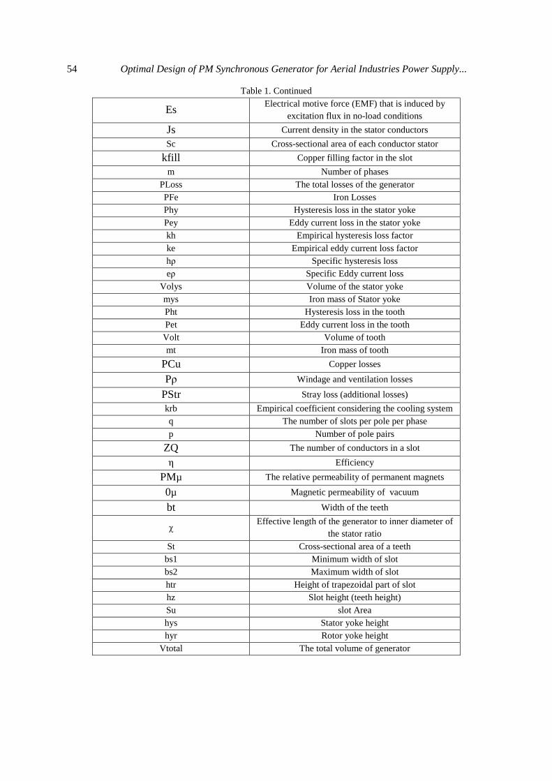
54 Optimal Design of PM Synchronous Generator for Aerial Industries Power Supply...
Table 1. Continued
Es Electrical motive force (EMF) that is induced by
excitation flux in no-load conditions
Js Current density in the stator conductors Sc Cross-sectional area of each conductor stator
kfill Copper filling factor in the slot m Number of phases
PLoss The total losses of the generator PFe Iron Losses Phy Hysteresis loss in the stator yoke Pey Eddy current loss in the stator yoke kh Empirical hysteresis loss factor ke Empirical eddy current loss factor hρ Specific hysteresis loss eρ Specific Eddy current loss
Volys Volume of the stator yoke mys Iron mass of Stator yoke Pht Hysteresis loss in the tooth Pet Eddy current loss in the tooth Volt Volume of tooth mt Iron mass of tooth
PCu Copper losses
Pρ Windage and ventilation losses
PStr Stray loss (additional losses) krb Empirical coefficient considering the cooling system q The number of slots per pole per phase p Number of pole pairs
ZQ The number of conductors in a slot
η Efficiency
PMµ The relative permeability of permanent magnets
0µ Magnetic permeability of vacuum
bt Width of the teeth
χ Effective length of the generator to inner diameter of the stator ratio
St Cross-sectional area of a teeth bs1 Minimum width of slot bs2 Maximum width of slot htr Height of trapezoidal part of slot hz Slot height (teeth height) Su slot Area hys Stator yoke height hyr Rotor yoke height
Vtotal The total volume of generator
55 A. Nikbakhsh et al.
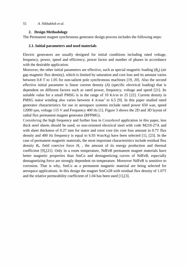
2. Design Methodology The Permanent magnet synchronous generator design process includes the following steps: 2.1. Initial parameters and used materials Electric generators are usually designed for initial conditions including rated voltage, frequency, power, speed and efficiency, power factor and number of phases in accordance with the desirable application. Moreover, the other initial parameters are effective, such as special magnetic loading (Bg) (air gap magnetic flux density), which is limited by saturation and core loss and its amount varies between 0.8 T to 1.05 for non-salient pole synchronous machines [19, 20]. Also the second effective initial parameter is linear current density (A) (specific electrical loading) that is dependent on different factors such as rated power, frequency, voltage and speed [21]. Its suitable value for a small PMSG is in the range of 10 KA/m to 25 [22]. Current density in PMSG stator winding also varies between 4 A/mm2 to 6.5 [9]. In this paper studied rated generator characteristics for use in aerospace systems include rated power 650 watt, speed 12000 rpm, voltage 115 V and Frequency 400 Hz [1]. Figure 3 shows the 2D and 3D layout of radial flux permanent magnet generator (RFPMG). Considering the high frequency and further loss in Considered application in this paper, less thick steel sheets should be used; so non-oriented electrical steel with code M210-27A and with sheet thickness of 0.27 mm for stator and rotor core (its core loss amount in 0.7T flux density and 400 Hz frequency is equal to 6.93 Watt/Kg) have been selected [1], [23]. In the case of permanent magnetic materials, the most important characteristics include residual flux density Br, field coercive force Hc , the amount of its energy production and thermal coefficient [9],[21]. Only in a room temperature, NdFeB permanent magnet materials have better magnetic properties than SmCo and demagnetizing curves of NdFeB, especially demagnetizing force are strongly dependent on temperature. Moreover NdFeB is sensitive to corrosion. That is why, SmCo as a permanent magnetic material are being selected for aerospace applications. In this design the magnet SmCo28 with residual flux density of 1.07T and the relative permeability coefficient of 1.04 has been used [1],[3].

56 Optimal Design of PM Synchronous Generator for Aerial Industries Power Supply...
Figure 3. 2D and 3D layout of radial flux permanent magnet generator (RFPMG)
2.2. Geometric dimensions of generator The most important geometrical dimensions of the generator include length of the generator and its stator outer diameter because these two almost determine the size of the generator. Among the main dimensions of the stator, inner and outer diameter of the stator core, stator yoke and tooth height and width and slot dimensions can be mentioned. Inner and outer diameter of the rotor, are the most important design parameters in the rotor [19]. Figure 4 represent the generator topology in order to show the geometric dimensions. Apparent electromagnetic power crossing the air gap is as follows:
)1( ���� = ����� = �√2������ ��� 2�√2�� = �2 ��������� ��� �� = 0.5��������� ��
In this equation nsyn is the rotor speed according to unit Turn/sec and Kw1 stands for winding factor which is related to the winding arrangement. Air gap magnetic flux density peak value is approximately equal to the peak value of its first harmonic (Bg1) which is following [22]:
)2( �� = 2π� ���.�����
��.�������� ��� = 4� ����� ����2
Primary amount of Bg in the ferrite permanent magnet material can also be estimated by Bg≈(0.4.........0.7)Br [22]. αPM is also equal to the ratio of the width of permanent magnet (bPM) to the pole pitch (τP). This αPM varies in the range between 0.6 to 0.9. In the generators having P pairs of poles, pole pitch (τP) equals to:
)3( �� = ��2�
Relations (4) and (5) indicate the generator output power and factor: )4( ���� = ��������� � = 1� ������� �
)5( � = ����� ������ = 0.5��� �� ��� �

57 A. Nikbakhsh et al.
Figure 4. Generator topology representing geometric dimensions [14].
In generators ε= Es/Vph =1.05.........1.45, which Es is the electrical motive force (EMF) that is induced by excitation flux in no-load conditions and Vph is the stator phase voltage. According to the relations (1), (4), (5) and considering χ = L/D, D internal diameter of the stator can be achieved based on equation (6).
)6( � = ������!�����
Which the value of χ for synchronous generators is equal to [19], [20]: )7( ! ≈ �
4"#"" > 1
)8( ! = 1… . .3" = 1
Finally the effective length of the generator is L=χ×D. The effective length should also be multiplied by laminated iron filling coefficient (Kst). Typically Kst varies between 0.9 to 0.97 .
)9( �� = � × $�� In the above equation, Li is the actual length of the generator. Also air gap length of the generator (g) can be estimated by relations (10):
)10( % = &��( ��' ) In equation (10), γ is a coefficient that its valuefor different types of generators is in the table in [20]. Based on experience, for small PMSG, the air gap length (g) is recommended between 0.3 mm to 1 [22]. Also in this design, semi-closed slots are considered for the generator because they provide more suitable strength, and lower slot coefficient, than open slots. To calculate the dimensions of slot and stator teeth, in the first step, the maximum magnetic flux density for the teeth and yoke should be chosen. The maximum amount of tooth flux
density Bt, 0.96 T and for the stator yoke Bys and rotor yoke flux density Byr, 0.71 T has been chosen [20]. Flux density in the teeth is equal to [19], [23]:

58 Optimal Design of PM Synchronous Generator for Aerial Industries Power Supply...
)11( �� = �� ����� )12( �� = ��(
In this equation tu is the slot pitch. As a result, the cross-sectional of tooth (St) and tooth width (bt) are [19], [20]:
)13( �� = �� ����� )14( )� = ����
Figure 5 shows the slot type in the studied design. Considering ZQ as the number of conductors in a slot and Nph as the number of coil turns in per phase, slot area (Su) will be as equation in (15) [19], [20]:
)15( �� = *��� $���� )16( *� = 2�( ��
)17( �� = ��2√2���
Kfill is the slot space filling factor by copper conductor that depends on voltage level, the type of material and winding type. For low voltage generators, Kfill typical value is between 0.5 to 0.6 and for high voltage generators it is between 0.3 to 0.45. Also in equation (15), the cross-section area of each conductor will be:
)18( �� = �� +� In the above equation, Js is the current density in a conductor and Is is the stator phase current.
Figure 5. slot type in the studied design
Now slot area is obtained from geometric relations as following:
)19( �� = 12 ()� + )�)ℎ��

59 A. Nikbakhsh et al.
htr is the height of the trapezoid part of the slot also bs1 and bs2 are the minimum and
maximum width of the slot respectively. Also bs1 and bs2 will be [19]: )20( )� + )� = �(� + 2(ℎ + ℎ))(
)21( )� + )� = �(� + 2ℎ��)(
Now, by solving equations (19), (20) and (21), two unknown parameters bs2 and htr, could be obtained. A slot opening of b1 is also as much as four times the radius of a conductor and the height h1 and h2 are both considered 1 mm. As a result, the slot height (hz) in equation (22) is estimated as bellow:
)22( ℎ� = ℎ + ℎ + ℎ�� Tooth height is also equal to the slot height. Also the height of stator yoke (hys) and the outer diameter of the stator (Dstot) are obtained as follows:
)23( ��� = ��)���
)24( ℎ�� =���2����
)25( ����� = � + 2(ℎ� + ℎ��) 2.3. Permanent magnets After selecting permanent magnet materials, first it must be determined how and where to mount permanent magnet on the rotor. The arrangements of PM rotors are divided into four categories: The surface mounted PM rotor, inset-type PM rotor, buried PM motors and interior-type PM motors [24]. In this design the structure of surface mounted PM rotor is selected since its construction is much easier to use. Then, the main dimensions of surface permanent magnets including permanent magnet thickness (hPM), width (bPM) and length (LPM) must be determined. Typically the width of the magnet (bPM) is 0.8 to 0.85 times of the pole pitch [25]. Magnet length will be equal to the effective length of the generator. Also the magnet thickness should be small enough in order to use fewer amounts of permanent magnet materials because the cost of providing these materials is very high. 0n the other hand, magnets should be thick enough to generate the required air gap magnetic flux density [19]. By calculating Carter coefficient, (Kc) with respect to the slot form, the equation of the permanent magnets thickness (hPM) will be as bellow [22], [26].
)26( �� = �� 1
1 + ,��. (�. �!������
���)⟹ ℎ�� = %. $� . ,��("�" − 2)
)27( $� = ���� − &%
)28( & = 4� -)2% ./�0.� 1)2%2− 3� 1 + ()2%)4 2.4. Losses

60 Optimal Design of PM Synchronous Generator for Aerial Industries Power Supply... Losses in electrical generators could be classified according to various bases. In studied application in this paper, the above-mention losses can be divided into four parts: the iron losses (PFe), which includes hysteresis and eddy current losses in the stator yoke and tooth; copper losses (PCu); windage-ventilation losses (Pρ) and stray (additional) losses (Pstr) [24]. Iron losses in the stator yoke consist of two parts: hysteresis losses (Phy) and eddy current losses (Pey), which these losses are proportional to frequency and the magnetic flux density [24], [27], [28]:
)29( �� = [$��5� + $��5�][���50 (
��1.5)
] )30( ��� = 5#� .��3�� )31( ��3�� = ��� 6(�����2 ) − (� + 2ℎ�
2 )7 In the above equation f is the frequency, By is the magnetic flux density in the stator yoke and khy and key are hysteresis empirical loss factor and eddy current empirical loss factor related to the type and thickness of sheet applied to the stator core respectively and ρh and ρe represent the specific hysteresis losses (Watt/Kg) and specific eddy current losses (Watt/Kg) respectively and ρFe is special weight of the sheets. In this paper , due to high frequency in the studied applications, for used stator and rotor core sheets (non-oriented electrical steel with code M210-27A) ρh and ρe values are high values of 6.93 and 2.05[1]; In this application high values of these coefficients, will result in losses increase and efficiency reduction of PMSG; while in other applications, because of low frequency, these coefficients, and hence losses of these generators, will have lower values and more efficiency. Also Volys and mys represent volume and mass of the stator yoke iron, respectively. Iron losses in the teeth will also be calculated by the above equation, considering the fact that Volt will be as the following:
)32( ��3� = 1����� − �2 − ℎ��2 )���(
Since the high-order harmonics in the stator current and the space harmonics in winding distribution are generally small, rotor eddy current losses in permanent magnet generator is typically negligible [24],[29]. Copper losses (PCu) and windage-ventilation losses (Pρ) could also be found in the following relations [9], [19], [20], [22] and [24]:
)33( �$� = �8%��� )34( �& = $�'�� 9� + 0.6��: (2����� ��2 )
)35( �� = � − 2% − 2ℎ��
In the above equation Dr is the rotor core diameter and krb is an empirical coefficient depending on the cooling system type and the size of generator can be determined, according to table [20]. The additional and stray losses are typically considered as a small percentage of the output power [19]:
)36( �(�� = 0.0075����
61 A. Nikbakhsh et al. 2.5. Efficiency and total volume of the generator At the end of the design process, the efficiency (η) and the total volume of the designed generator (Vtotal) will be calculated as the following:
)37( ; = ������� = �������� + �#�+�$� + �& + �(�� )38( ����%� = ������4 �
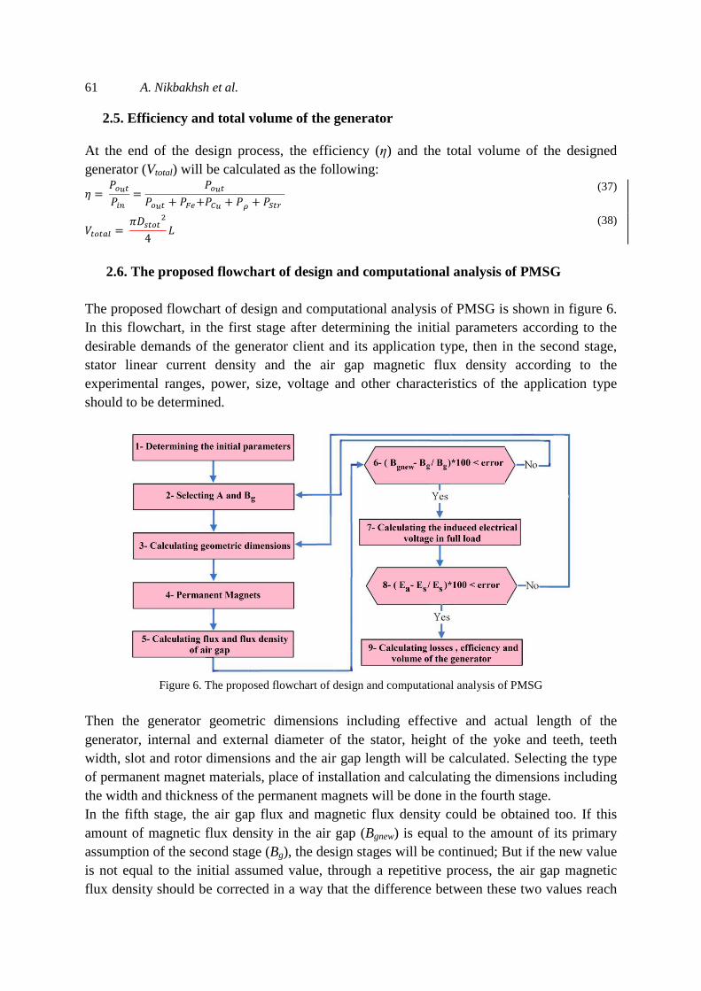
2.6. The proposed flowchart of design and computational analysis of PMSG The proposed flowchart of design and computational analysis of PMSG is shown in figure 6. In this flowchart, in the first stage after determining the initial parameters according to the desirable demands of the generator client and its application type, then in the second stage, stator linear current density and the air gap magnetic flux density according to the experimental ranges, power, size, voltage and other characteristics of the application type should to be determined.
Figure 6. The proposed flowchart of design and computational analysis of PMSG
Then the generator geometric dimensions including effective and actual length of the generator, internal and external diameter of the stator, height of the yoke and teeth, teeth width, slot and rotor dimensions and the air gap length will be calculated. Selecting the type of permanent magnet materials, place of installation and calculating the dimensions including the width and thickness of the permanent magnets will be done in the fourth stage. In the fifth stage, the air gap flux and magnetic flux density could be obtained too. If this amount of magnetic flux density in the air gap (Bgnew) is equal to the amount of its primary assumption of the second stage (Bg), the design stages will be continued; But if the new value is not equal to the initial assumed value, through a repetitive process, the air gap magnetic flux density should be corrected in a way that the difference between these two values reach

62 Optimal Design of PM Synchronous Generator for Aerial Industries Power Supply... to less than one percent. Then in the seventh stage, the induced electrical voltage in full load (Ea) is calculated. Steps 3 to 8 will repeat until the voltage (Ea) comparison to the no-load induced voltage (Es), does not change more than one percent. In the next steps losses, efficiency and the size of the generator will be calculated. Now, according to the desired purposes in intended application and the relationship between output quantities and input parameters, through this model and the analytical method and full search in the range of input parameters, the optimal solution related to all the design parameters could be found.
3. Optimization
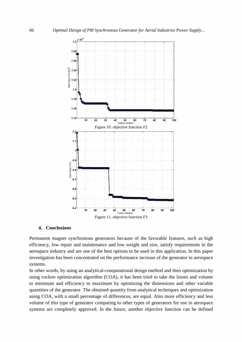
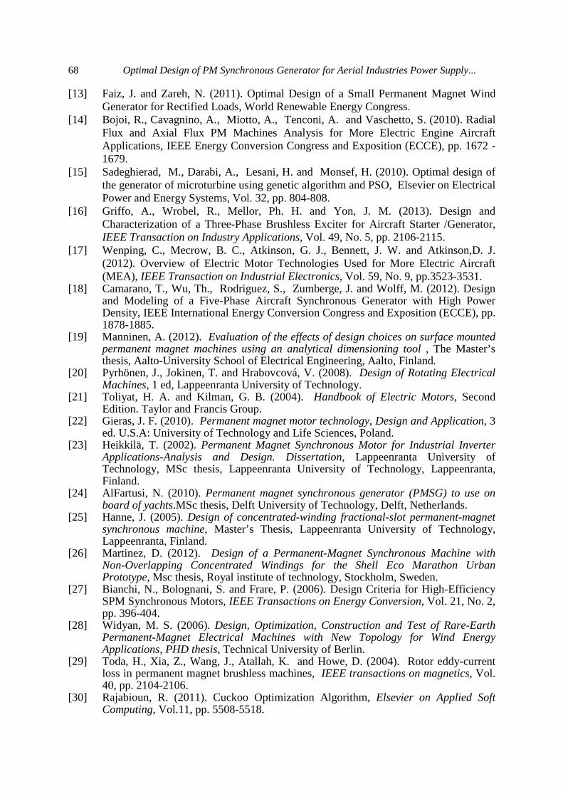
Optimization of PMSG is a multi-objective optimization problem with multiple variables and constraints. The optimization process will be in three stages: In the first stage optimization variables which are the same as the generator modifiable input parameters are defined. Secondly, the objective functions and constraints are formulated. In this paper objective functions include efficiency, volume and a combination of efficiency and volume. In the third phase, an optimization algorithm is used for finding the generator’s optimal geometric dimensions and other quantities of it [9]. 3.1. Optimization purposes In this optimization, finding the maximum of the objective function F1 related to the efficiency (η) according to equation (37) (Since through this optimization method, we will find the minimum of the objective functions, in order to find the maximum of efficiency, we should optimized function (1/F1) to achieve the value of maximum efficiency), and finding the minimum of the objective function F2 related to the total volume of the generator (Vtotal) according to equation (38) also finding the optimal objective function F3 related to the simultaneous optimization of efficiency and total volume of the generator according to equation (39), are considered.
)39( <) = �<+�< Which in equation (39) α1 and α2 are set so that, through optimization, efficiency reach to its maximum value and volume to its minimum value. The variation ranges of eight generator adjustable design parameters are listed in Table 2.
Table 2: Variation range of the generator design input parameters
g(mm) P Q B(T) A(A/m) αPM χ ϵ [0.5;1.5] [2;6] [12;36] [0.62;0.83] [10000 ; 22000] [0.6; 0.9] [0.14;0.6] [1.05; 1.45]
3.2. Cuckoo Optimization Algorithm (COA) In this paper, the optimization of PMSG has been performed by Cuckoo Optimization Algorithm (COA). This algorithm is about a new evolutionary algorithm. This optimization algorithm has loaned the life style of a bird family which is called cuckoo. Because of the special characteristics of these birds’ life style and the way they lay their eggs and their

63 A. Nikbakhsh et al. breeding, cuckoo optimization algorithm has concentrated based on it. COA begins with a primary population, as it is the case in other revolutionary methods. The cuckoo population, in different societies, consists of two types including mature cuckoos and eggs [30]. Endeavor for survival among cuckoos is the best of cuckoo optimization algorithm. This is the case of a competition to live after the death of the others in a society. During this survival competition some cuckoos or their eggs will die. The cuckoo societies which have survived migrate to a better environment. There, they start reproduction and laying eggs [30]. In other words, mother cuckoos never build their own nests and lay eggs in some other birds nest. These eggs grow and become mother cuckoos, if they are not recognized and killed by host birds. Therefore, groups (societies) of cuckoos immigrate to find the best environment for reproduction. Figure 7 shows the immigration of a sample cuckoo toward goal habitat.
Figure 7. Immigration of a sample cuckoo toward goal habitat [30].
The effort to survive among cuckoos ends when there is only one cuckoo society which all has the same profit values [30]. Also the flowchart of COA is illustrated in Fig 8.
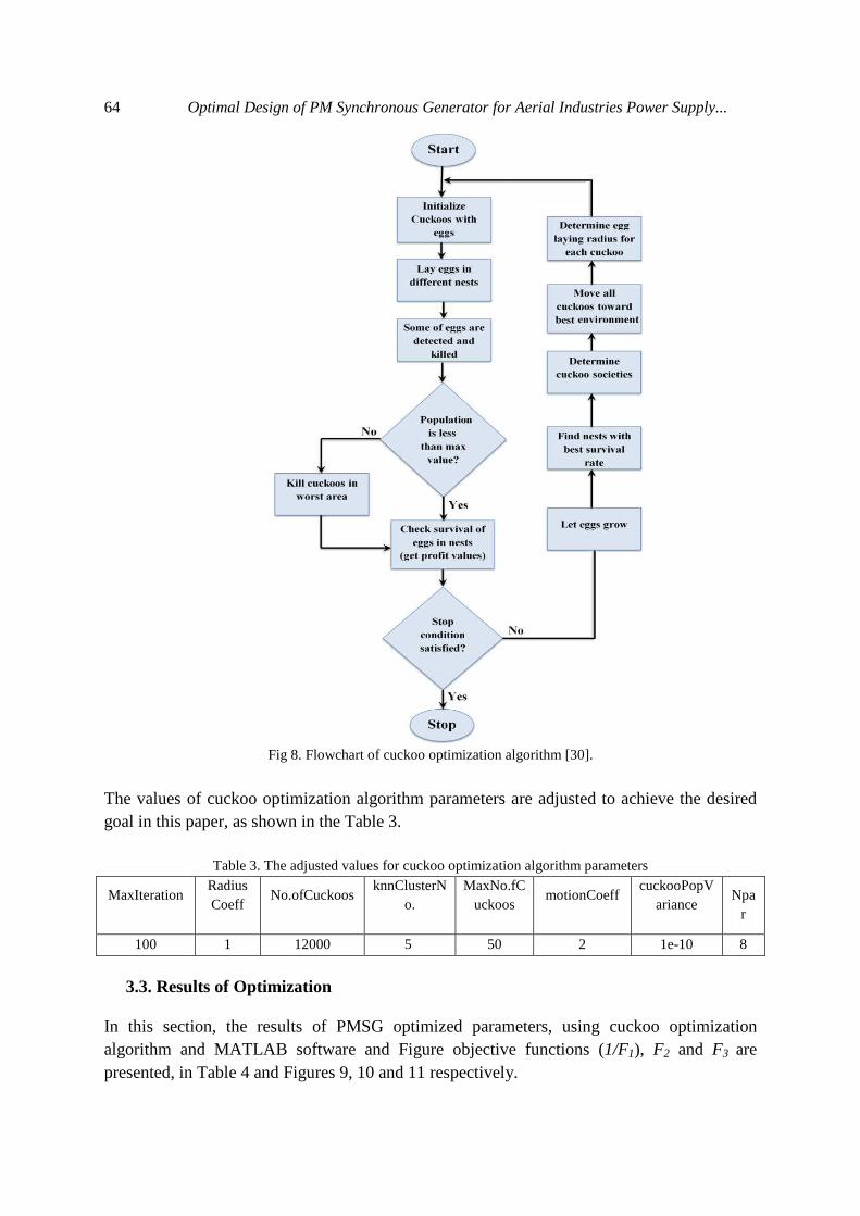
64 Optimal Design of PM Synchronous Generator for Aerial Industries Power Supply...
Fig 8. Flowchart of cuckoo optimization algorithm [30].
The values of cuckoo optimization algorithm parameters are adjusted to achieve the desired goal in this paper, as shown in the Table 3.
Table 3. The adjusted values for cuckoo optimization algorithm parameters
Npar
cuckooPopVariance
motionCoeff
MaxNo.fCuckoos
knnClusterNo.
No.ofCuckoos
RadiusCoeff
MaxIteration
8 1e-10 2 50 5 12000 1 100
3.3. Results of Optimization In this section, the results of PMSG optimized parameters, using cuckoo optimization algorithm and MATLAB software and Figure objective functions (1/F1), F2 and F3 are presented, in Table 4 and Figures 9, 10 and 11 respectively.

65 A. Nikbakhsh et al.
Table 4. Optimization Results Optimization Combination of efficiency and volume
Optimization of Volume
Optimization of efficiency
The objective of optimization
Quantity of generator
113.6 124 90.1 Dstot (mm) 56.5 63.7 43.8 D (mm) 11.6 9.6 19.8 L (mm) 13.9 14.4 12.8 hz (mm) 4.1 4.4 3.5 bs2 (mm) 2 2.2 1.6 bs1 (mm)
3.3 3.7 2.5 bt (mm) 47.1 54.6 33.1 Dr (mm) 3.7 3.5 4.2 hPM (mm) 14.7 15.8 10.3 hys (mm) 14.7 15.8 10.3 hyr (mm) 186 216 144 Nph
31 36 24 Zq
85.75 92.28 81 PLoss(Watt) 75.19 77.07 73.2 Ea ( volt ) 75.38 77.42 73.32 Es ( volt ) 88.35 87.57 89 ( % )η 117.18 115.71 126.25 Vtotal (cm3) 133.67 133.3 134.86 Cost ( $ )
21996.66 21998.14 21951.19 A (A/m) 0.62 0.62 0.62 Bg (T)
4 4 4 2P 36 36 36 Q 1.1 1 1.16 g(mm) 0.74 0.7 0.667 αPM 0.21 0.151 0.452 χ 1.14 1.17 1.11 ϵ
Figure 9. objective function (1/ F1)
66 Optimal Design of PM Synchronous Generator for Aerial Industries Power Supply...
Figure 10. objective function F2
Figure 11. objective function F3
4. Conclusions
Permanent magnet synchronous generators because of the favorable features, such as high efficiency, low repair and maintenance and low weight and size, satisfy requirements in the aerospace industry and are one of the best options to be used in this application. In this paper investigation has been concentrated on the performance increase of the generator in aerospace systems. In other words, by using an analytical-computational design method and then optimization by using cuckoo optimization algorithm (COA), it has been tried to take the losses and volume to minimum and efficiency to maximum by optimizing the dimensions and other variable quantities of the generator. The obtained quantity from analytical techniques and optimization using COA, with a small percentage of differences, are equal. Also more efficiency and less volume of this type of generator comparing to other types of generators for use in aerospace systems are completely approved. In the future, another objective function can be defined

67 A. Nikbakhsh et al. such as the power density and the cost of the generator production and by other optimization methods such as bees, ants, particle swarm, imperialist and genetic optimization algorithm, optimizing can be used for these purposes. The PMSG design optimization studied in this paper leads to a 2.78% increase in efficiency in a mode that the objective function is a mere maximization of the efficiency than that of reference [1] and efficiency has increased by 89%. Also by optimization just for minimizing the total volume of the generator, the volume has decreased by 115.71 cm3. Whereas in simultaneous optimization of efficiency and total volume of the generator, maximum efficiency has reduced by 0.65% and minimum volume has increased by as much as 1.47 cm3, in comparison to the time when these two quantities have been optimized individually.
References
[1] Shirzadi, A. (2011). Design and analysis of a high speed brushless direct current motor for the aerospace industry, Nineteenth Iranian Conference on Electrical Engineering, Amirkabir University of Technology.
[2] Richie, D. and Lappas, VJ. (2009). A practical small satellite variablespeed control moment gyroscope for combined energy storage and attitude control, Elsevier Ltd. Acta Astronautica, Vol. 65, pp. 1745- 1764.
[3] Mhango, L.M.C.and Perryman, R. (2006). High efficiency and high speed PM motors for the more electric aircraft, In Proceeding of the1st Annual Conference on Advances in Computing and Technology,The School of Computing and Technology,Portugal, pp. 149-157.
[4] Nagorny, A. S., Dravid, N. V., Jansen, R. H. and Kenny, B. H. (2005). Design Aspects of a High Speed Permanent Magnet Synchronous Motor/Generator for Flywheel Applications, IEEE International Electric Machines and Drives Conference.
[5] Jones, RI. (1999). The more electric aircraft: The past and the future, IEEE Colloquium on Electrical Machines and Systems for the More Electric Aircraft.
[6] Gieras, J. F. (2013). Electric Power System of Tu-154M Passenger Aircraft, Przeglad Eektrotechniczny1.
[7] Bojoi, R., Cavagnino, A., Miotto, A., Tenconi, A. and Vaschetto, S. (2012). Multiphase PM Machine for More Electric Aircraft Applications: Prototype for Design Validation, 38th Annual Conference on IEEE Industrial Electronics Society.
[8] Tapia, J. A., Pyrhönen, J., Puranen, J., Lindh, P. and Nyman, S. (2013). Optimal Design of Large Permanent Magnet Synchronous Generators, IEEE Transactions on Magnetics, Vol. 49, No. 1. pp. 642-650.
[9] Soleimani Keshayeh, M. J. and Gholamian, S. A. (2013). Optimum Design of a Three-Phase Permanent Magnet Synchronous Motor for industrial applications, International Journal of Applied Operational Research ,Vol. 2, No. 4, pp. 67-86.
[10] Tao, W. and Qingfeng, W. (2012). Optimization Design of a Permanent Magnet Synchronous Generator for a Potential Energy Recovery System.IEEE Transaction on Energy Conversion, Vol. 27, No. 4,pp. 856-863.
[11] Baoquan, K., Haichuan, C., Da, Zh.,Weili, L. andXiaochen, Zh. (2012).Structural Optimization of High Speed Permanent Magnet Synchronous Motor for Flywheel Energy Storage.In Proceeding of the16th International Symposium on Electromagnetic Launch Technology (EML), IEEE Press, pp.1-7.
[12] Wallace, R., Alexandrova, J., Vera, B., Tapia, J., Pyrhönen, J. and Lindh, P. (2012). P.M Synchronous Generator Design Analytical Metod, International IEEE Symposium on Power Electronics, Electrical Drives, Automation and Motion.
68 Optimal Design of PM Synchronous Generator for Aerial Industries Power Supply... [13] Faiz, J. and Zareh, N. (2011). Optimal Design of a Small Permanent Magnet Wind
Generator for Rectified Loads, World Renewable Energy Congress. [14] Bojoi, R., Cavagnino, A., Miotto, A., Tenconi, A. and Vaschetto, S. (2010). Radial
Flux and Axial Flux PM Machines Analysis for More Electric Engine Aircraft Applications, IEEE Energy Conversion Congress and Exposition (ECCE), pp. 1672 - 1679.
[15] Sadeghierad, M., Darabi, A., Lesani, H. and Monsef, H. (2010). Optimal design of the generator of microturbine using genetic algorithm and PSO, Elsevier on Electrical Power and Energy Systems, Vol. 32, pp. 804-808.
[16] Griffo, A., Wrobel, R., Mellor, Ph. H. and Yon, J. M. (2013). Design and Characterization of a Three-Phase Brushless Exciter for Aircraft Starter /Generator, IEEE Transaction on Industry Applications, Vol. 49, No. 5, pp. 2106-2115.
[17] Wenping, C., Mecrow, B. C., Atkinson, G. J., Bennett, J. W. and Atkinson,D. J. (2012). Overview of Electric Motor Technologies Used for More Electric Aircraft (MEA), IEEE Transaction on Industrial Electronics, Vol. 59, No. 9, pp.3523-3531.
[18] Camarano, T., Wu, Th., Rodriguez, S., Zumberge, J. and Wolff, M. (2012). Design and Modeling of a Five-Phase Aircraft Synchronous Generator with High Power Density, IEEE International Energy Conversion Congress and Exposition (ECCE), pp. 1878-1885.
[19] Manninen, A. (2012). Evaluation of the effects of design choices on surface mounted permanent magnet machines using an analytical dimensioning tool , The Master’s thesis, Aalto-University School of Electrical Engineering, Aalto, Finland.
[20] Pyrhönen, J., Jokinen, T. and Hrabovcová, V. (2008). Design of Rotating Electrical Machines, 1 ed, Lappeenranta University of Technology.
[21] Toliyat, H. A. and Kilman, G. B. (2004). Handbook of Electric Motors, Second Edition. Taylor and Francis Group.
[22] Gieras, J. F. (2010). Permanent magnet motor technology, Design and Application, 3 ed. U.S.A: University of Technology and Life Sciences, Poland.
[23] Heikkilä, T. (2002). Permanent Magnet Synchronous Motor for Industrial Inverter Applications-Analysis and Design. Dissertation, Lappeenranta University of Technology, MSc thesis, Lappeenranta University of Technology, Lappeenranta, Finland.
[24] AlFartusi, N. (2010). Permanent magnet synchronous generator (PMSG) to use on board of yachts.MSc thesis, Delft University of Technology, Delft, Netherlands.
[25] Hanne, J. (2005). Design of concentrated-winding fractional-slot permanent-magnet synchronous machine, Master’s Thesis, Lappeenranta University of Technology, Lappeenranta, Finland.
[26] Martinez, D. (2012). Design of a Permanent-Magnet Synchronous Machine with Non-Overlapping Concentrated Windings for the Shell Eco Marathon Urban Prototype, Msc thesis, Royal institute of technology, Stockholm, Sweden.
[27] Bianchi, N., Bolognani, S. and Frare, P. (2006). Design Criteria for High-Efficiency SPM Synchronous Motors, IEEE Transactions on Energy Conversion, Vol. 21, No. 2, pp. 396-404.
[28] Widyan, M. S. (2006). Design, Optimization, Construction and Test of Rare-Earth Permanent-Magnet Electrical Machines with New Topology for Wind Energy Applications, PHD thesis, Technical University of Berlin.
[29] Toda, H., Xia, Z., Wang, J., Atallah, K. and Howe, D. (2004). Rotor eddy-current loss in permanent magnet brushless machines, IEEE transactions on magnetics, Vol. 40, pp. 2104-2106.
[30] Rajabioun, R. (2011). Cuckoo Optimization Algorithm, Elsevier on Applied Soft Computing, Vol.11, pp. 5508-5518.