Optimal Design of Multi-Machine Power System Stabilizer
18
Innovative Systems Design and Engineering www.iiste.org ISSN 2222-1727 (Paper) ISSN 2222-2871 (Online) Vol 2, No 3 54 Optimal Design of Multi-Machine Power System Stabilizer Using Genetic Algorithm G.Naresh (Corresponding author) Department of EEE, Pragati Engineering College, Surampalem E.G. District, Andhra Pradesh, INDIA. [email protected] M.Ramalinga Raju, K.Ravindra Department of EEE, UCEK, J.N.T.U. Kakinada E.G. District, Andhra Pradesh, INDIA. S.V.L.Narasimham Department of CSE, School of IT, J.N.T.U. Hyderabad Hyderabad, Andhra Pradesh, INDIA Abstract Power system stabilizers (PSSs) are used to generate supplementary control signals for the excitation system to damp electromechanical oscillations. This paper presents an approach based on genetic algorithm for tuning the parameters of PSSs in a multi-machine power system. The stabilizers are tuned to simultaneously shift the lightly damped and undamped electromechanical modes of all plants to a prescribed zone in the s-plane. A multiobjective problem is formulated to optimize a composite set of objective functions comprising the damping factor, and the damping ratio of the lightly damped electromechanical modes. The performance of the proposed PSSs under different disturbances, loading conditions, and system configurations is investigated for different multi-machine power systems. The non-linear simulation results are presented under wide range of operating conditions; disturbances at different locations as well as for various fault clearing sequences to show the effectiveness and robustness of the proposed PSSs and their ability to provide efficient damping of low frequency oscillations. Keywords: Power System Stabilizer, Electromechanical Oscillations, Genetic algorithm, Multi-machine power system. 1. Introduction Damping of electromechanical oscillations in multi-machine power systems is the most important issue for a secure operation. Rogers et al. (1999) have reported that these oscillations may sustain and grow to cause system separation if no adequate damping is available. A well established classification separates them into two types: (i) local mode, corresponds to an oscillations of one or more generators in an area with respect to the rest of the system. Pai (2004) states that the local mode has a frequency of 1-3.0 Hz. (ii) Inter-area mode oscillations, is concerned with the oscillations of a group of generators in one area against a group in another area, usually connected by a long or a weak tie line. Bikash Pal (2005) states that these oscillations usually in a frequency range between 0.2-1 Hz. A common approach to damp these oscillations and improve system dynamic stability is the use of conventional lead-lag power system stabilizers (CPSSs). Rouco (2001) argued that these power system stabilizers are effective in damping local modes, and if carefully optimized may also be effective in damping inter-area modes up to a certain transmission loading .
Transcript of Optimal Design of Multi-Machine Power System Stabilizer

Innovative Systems Design and Engineering www.iiste.org
ISSN 2222-1727 (Paper) ISSN 2222-2871 (Online)
Vol 2, No 3
54
Optimal Design of Multi-Machine Power System Stabilizer
Using Genetic Algorithm
G.Naresh (Corresponding author)
Department of EEE, Pragati Engineering College, Surampalem
E.G. District, Andhra Pradesh, INDIA.
M.Ramalinga Raju, K.Ravindra
Department of EEE, UCEK, J.N.T.U. Kakinada
E.G. District, Andhra Pradesh, INDIA.
S.V.L.Narasimham
Department of CSE, School of IT, J.N.T.U. Hyderabad
Hyderabad, Andhra Pradesh, INDIA
Abstract
Power system stabilizers (PSSs) are used to generate supplementary control signals for the excitation
system to damp electromechanical oscillations. This paper presents an approach based on genetic algorithm
for tuning the parameters of PSSs in a multi-machine power system. The stabilizers are tuned to
simultaneously shift the lightly damped and undamped electromechanical modes of all plants to a
prescribed zone in the s-plane. A multiobjective problem is formulated to optimize a composite set of
objective functions comprising the damping factor, and the damping ratio of the lightly damped
electromechanical modes. The performance of the proposed PSSs under different disturbances, loading
conditions, and system configurations is investigated for different multi-machine power systems. The
non-linear simulation results are presented under wide range of operating conditions; disturbances at
different locations as well as for various fault clearing sequences to show the effectiveness and robustness
of the proposed PSSs and their ability to provide efficient damping of low frequency oscillations.
Keywords: Power System Stabilizer, Electromechanical Oscillations, Genetic algorithm, Multi-machine
power system.
1. Introduction
Damping of electromechanical oscillations in multi-machine power systems is the most important issue for
a secure operation. Rogers et al. (1999) have reported that these oscillations may sustain and grow to cause
system separation if no adequate damping is available. A well established classification separates them into
two types: (i) local mode, corresponds to an oscillations of one or more generators in an area with respect to
the rest of the system. Pai (2004) states that the local mode has a frequency of 1-3.0 Hz. (ii) Inter-area mode
oscillations, is concerned with the oscillations of a group of generators in one area against a group in
another area, usually connected by a long or a weak tie line. Bikash Pal (2005) states that these oscillations
usually in a frequency range between 0.2-1 Hz. A common approach to damp these oscillations and
improve system dynamic stability is the use of conventional lead-lag power system stabilizers (CPSSs).
Rouco (2001) argued that these power system stabilizers are effective in damping local modes, and if
carefully optimized may also be effective in damping inter-area modes up to a certain transmission
loading .
Innovative Systems Design and Engineering www.iiste.org
ISSN 2222-1727 (Paper) ISSN 2222-2871 (Online)
Vol 2, No 3
55
Design of CPSS is based on the linear control theory which requires a nominal power system model
formulated as linear, time invariant system. CPSS based on this approach can be very well tuned to an
operating condition and will provide excellent damping over a certain range around the design point.
However, CPSS parameters may not be optimal for the whole set of possible operating conditions and
configurations. Larsen (1981) and Tse (1993) argued that despite the potential of modern control techniques
with different structures, power system utilities still prefer a conventional lead-lag power system stabilizer
(CPSS) structure. The reasons behind that might be the ease of online tuning and the lack of assurance of
the stability related to some adaptive or variable structure techniques. Kundur et al. have presented a
comprehensive analysis of the effects of the different CPSS parameters on the overall dynamic performance
of the power system. It is shown that the appropriate selection of CPSS parameters results in satisfactory
performance during system upsets.
Many different techniques has been reported in the literature pertaining to optimum location and
coordinated design problems of CPSSs. Generally, most of these techniques are based on phase
compensation and eigen value assignment. Fleming (1981), Abe (1983) and Arredondo(1997) presented
different techniques of sequential design of PSSs to damp out one of the electromechanical modes at a time.
Generally, the dynamic interaction effects among various modes of the machines are found to have
significant influence on the stabilizer settings. Therefore, considering the application of stabilizer to one
machine at a time may not finally lead to an overall optimal choice of PSS parameters. Moreover, the
stabilizers designed to damp one mode can produce adverse effects in other modes. In addition, the optimal
sequence of design is a very involved question. The sequential design of PSSs is avoided by Gooi (1981),
Lefebvre(1983), Lim(1985), Chen(1987) and Yu(1990), where various methods for simultaneous tuning of
PSSs in multi-machine power systems are proposed. Unfortunately, the proposed techniques are iterative
and require heavy computation burden due to system reduction procedure. This gives rise to time
consuming computer codes. In addition, the initialization step of these algorithms is crucial and affects the
final dynamic response of the controlled system. Hence, different designs assigning the same set of eigen
values were simply obtained by using different initializations. Therefore, a final selection criterion is
required to avoid long runs of validation tests on the nonlinear model.
Recently, genetic algorithms (GAs) have received much attention as an effect method to find global or near
global solution of difficult and complex design problems. Compared with the other conventional methods
described above, mathematical properties such as differentiability, convexity and nonlinearity are of no
concern. Abdel Magid (1999),Schmitendorf(1992) and Hasanovic (2002) argued that another advantage of
GAs is that they can be easily coupled with already developed analysis and simulation tools .
In this paper optimization of the parameters of CPSS using GA is proposed. A multiobjective problem is
formulated to optimize a composite set of objective functions comprising the damping factor, and the
damping ratio of the lightly damped electromechanical modes. The problem of robustly selecting the
parameters of the power system stabilizers is converted to an optimization problem which is solved by GA
with the eigen value-based multiobjective function. Eigen value analysis and nonlinear simulation results
have been carried out to assess the effectiveness of the proposed PSSs under different disturbances, loading
conditions, and system configurations. Results obtained from eigenvalues and nonlinear time domain
simulation are compared with results that obtained by CPSS.
2. Problem Statement
2.1 Power system model
A power system can be modelled by a set of nonlinear differential equations as f( X, U)X
, where X is
the vector of the state variables, and U is the vector of input variables. In this study, all the generators in
the power system are represented by their fourth order model and the problem is to design the parameters of
the power system stabilizers so as to stabilize a system of ‘N’ generators simultaneously. The fourth order
power system model is represented by a set of non-linear differential equations given for any ith
machine,

Innovative Systems Design and Engineering www.iiste.org
ISSN 2222-1727 (Paper) ISSN 2222-2871 (Online)
Vol 2, No 3
56
sωiω dt
idδ
(1)
)(2
sω dt
idω
eiPmiPH
(2)
])'('[
id0T
1
dt
'd
fdiEdiXdiXdiIqiEqiE
(3)
)]'('['q0iT
1
dt
'd
qiXqiXqiIdiEdiE
(4)
)]([
aiT
1
dt
d
tiVrefiVaiKfdiEfdiE
(5)
qiIdiIdixqixqiIqiEdiI'diEeiT )''('
(6)
where d and q direct and quadrature axes,
i and i are rotor angle and angular speed of the machine,
miP and eiP the mechanical input and electrical output power,
'diE and
'qiE are the d-axis and q-axis transient emf due to field flux ,
fdiE , diI and qiI are the field voltage, d-axis stator current and q- axis stator current,
diX , 'diX and qiX ,
'qiX are reactance along d-q axes,
'
0dT , '0qT are d-q axes open circuit time constants,
aiK , aiT are AVR gain and time constant
refiV , tiV are the reference and terminal voltages of the machine
For a given operating condition, the multi-machine power system is linearized around the operating point.
The closed loop eigen values of the system are computed and the desired objective function is formulated
using only the unstable or lightly damped electromechanical eigen values, keeping the constraints of
keeping all the system modes stable under any condition.
2.2 PSS Structure

Innovative Systems Design and Engineering www.iiste.org
ISSN 2222-1727 (Paper) ISSN 2222-2871 (Online)
Vol 2, No 3
57
The speed based conventional PSS is considered in the study. The transfer function of the PSS is as given
below.
)( )41( )21(
)31( )11(
1 si
isTisT
isTisT
wisT
wisTiKsiU
(7)
where is the deviation of the speed of the rotor from synchronous speed. The second term in Eq. (7)
is the washout term with a time constant of wT . The third term is the lead–lag compensation to counter the
phase lag through the system. The washout block serves as a high-pass filter to allow signals in the range of
0.2–2.0 Hz associated with rotor oscillations to pass unchanged. This can be achieved by choosing a high
value of time constant ( wT ). However, it should not be so high that, it may create undesirable generator
voltage excursions during system-islanding. Compromising, it may have a value anywhere in the range of
1–20 s . On the other hand, the lead–lag block present in the system provides phase lead (some rare cases
lag also) compensation for the phase lag that is introduced in the circuit between the exciter input (i.e. PSS
output) and the electrical torque. In this study the parameters to be optimized are{ iK , i T1 , i T2 ; i=1,2
3,...m },assuming iT1 = iT3 and iT2 = iT4 .
2.3 Objective Function
1) To have some degree of relative stability. The parameters of the PSS may be selected to minimize the
following objective function:
2],1 0,
0[ 1 ji
np
j ji
J
(8)
where ‘ np ’ is the number of operating points considered in the design process, and ji, is the real part of
the ith
eigen value of the jth
operating point, subject to the constraints that finite bounds are placed on the
power system stabilizer parameters. The relative stability is determined by the value of 0 . This will
place the closed-loop eigenvalues in a sector in which as shown in Fig. 1.
Figure 1: Closed loop eigenvalues in a sector
2) To limit the maximum overshoot, the parameters of the PSS may be selected to minimize the following
0
j 0, ji

Innovative Systems Design and Engineering www.iiste.org
ISSN 2222-1727 (Paper) ISSN 2222-2871 (Online)
Vol 2, No 3
58
objective function:
2],1 0,
0[ 2 ji
np
j ji
J
(9)
where ji, is the damping ratio of the ith
eigen value of the jth
operating point. This will place the
closed-loop eigenvalues in a wedge-shape sector in which ji, > 0 as shown in Fig. 2.
Figure 2: Representation of eigenvalues in wedge shape sector
3) The single objective problems described may be converted to a multiple objective problem by assigning
distinct weights to each objective. In this case, the conditions 0, ji and 0, ji are imposed
simultaneously. The parameters of the PSS may be selected to minimize the following objective function:
2 a. 1 JJJ = 2],
1 0, 0[ ji
np
j ji
+ a 2],1 0,
0[ ji
np
j ji
(10)
This will place the system closed-loop eigenvalues in the D-shape sector characterized by 0, ji and
0, ji as shown in Fig. 3.
Figure 3: Representation of eigenvalues in D-shape sector
j
0,
0,
ji
ji
j
0, ji
Innovative Systems Design and Engineering www.iiste.org
ISSN 2222-1727 (Paper) ISSN 2222-2871 (Online)
Vol 2, No 3
59
It is necessary to mention here that only the unstable or lightly damped electromechanical modes of
oscillations are relocated. The design problem can be formulated as the following constrained optimization
problem, where the constraints are the PSS parameter bounds:
Minimize J subject to
i Ki K iK
maxmin
i Ti T iT
max11min1
i Ti T iT
max22min2
The proposed approach employs GA to solve this optimization problem and search for optimal or near
optimal set of PSS parameters { iK , i T1 , i T2 ; i=1,2 3,...m} where ‘m ‘is the number of machines.
Typical ranges of the optimized parameters are [0.01, 50] for iK and [0.01 to 1.0] for i T1 and i T2 .
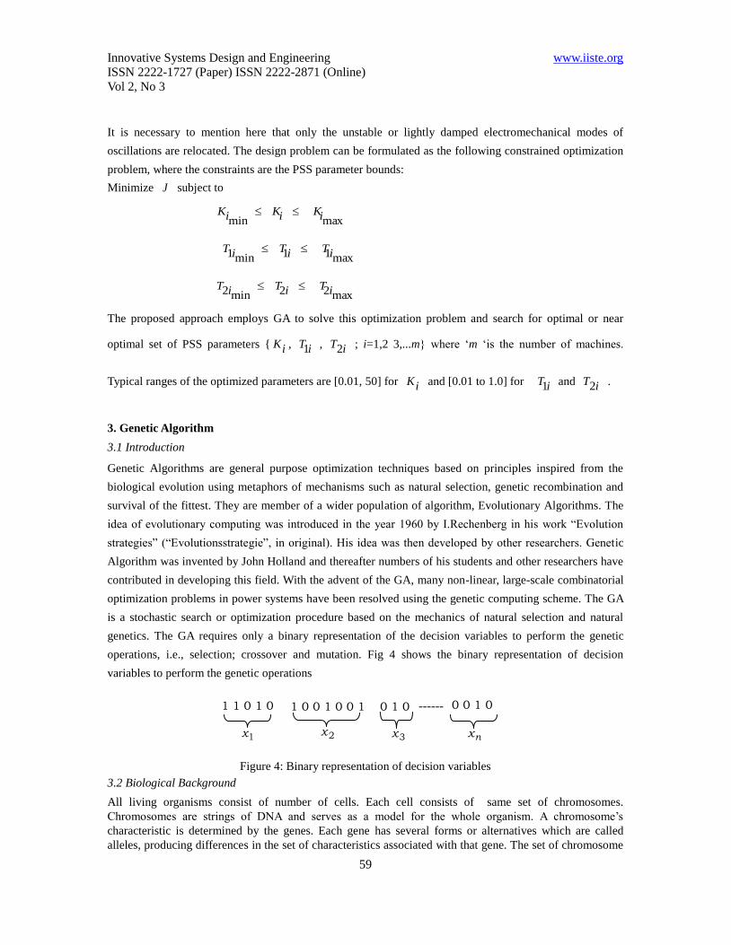
3. Genetic Algorithm
3.1 Introduction
Genetic Algorithms are general purpose optimization techniques based on principles inspired from the
biological evolution using metaphors of mechanisms such as natural selection, genetic recombination and
survival of the fittest. They are member of a wider population of algorithm, Evolutionary Algorithms. The
idea of evolutionary computing was introduced in the year 1960 by I.Rechenberg in his work “Evolution
strategies” (“Evolutionsstrategie”, in original). His idea was then developed by other researchers. Genetic
Algorithm was invented by John Holland and thereafter numbers of his students and other researchers have
contributed in developing this field. With the advent of the GA, many non-linear, large-scale combinatorial
optimization problems in power systems have been resolved using the genetic computing scheme. The GA
is a stochastic search or optimization procedure based on the mechanics of natural selection and natural
genetics. The GA requires only a binary representation of the decision variables to perform the genetic
operations, i.e., selection; crossover and mutation. Fig 4 shows the binary representation of decision
variables to perform the genetic operations
Figure 4: Binary representation of decision variables
3.2 Biological Background
All living organisms consist of number of cells. Each cell consists of same set of chromosomes.
Chromosomes are strings of DNA and serves as a model for the whole organism. A chromosome’s
characteristic is determined by the genes. Each gene has several forms or alternatives which are called
alleles, producing differences in the set of characteristics associated with that gene. The set of chromosome
------ 1 1 0 1 0
1x
1 0 0 1 0 0 1
2x
0 1 0
3x
0 0 1 0
nx

Innovative Systems Design and Engineering www.iiste.org
ISSN 2222-1727 (Paper) ISSN 2222-2871 (Online)
Vol 2, No 3
60
which defines a phenotype (individual) with certain fitness is called the genotype. The fitness of an
organism is measured by success of the organism in its life. According to Darwinian theory the highly fit
individuals are given opportunities to reproduce whereas the least fit members of the population are less
likely to get selected for reproduction and so “die out”.
3.3Working mechanism of GA:
In nature, a combination of natural selection and procreation permits the development of living species that
are highly adapted to their environments. GA is an algorithm that operates on a similar principle. When
applied to a problem the standard genetic algorithm proceeds as follows: an initial population of individuals
(represented by chromosomes) ‘n’ is generated at random. At every evolutionary step, called as generation,
the individuals in the current population are decoded and evaluated according to predefined quality
criterion referred to as fitness function. To form a new population (next generation), individuals are selected
according to their fitness. Then some or all of the existing members of the current solution pool are
replaced with the newly created members. Creation of new members is done by crossover and mutation
operators.
3.3.1. Selection: According to Darwin’s evolution theory the best ones should survive and create new
offspring. There are many methods to select the best chromosomes, for example roulette wheel selection,
rank selection, steady state selection etc. Roulette wheel selection method has been used in this work to
select the chromosomes for crossover because of its simplicity and also the fitness values do not differ very
much in this work.
Roulette wheel selection: Parents are selected according to their fitness. The better the chromosomes are,
the more chances to be selected they have. A roulette wheel (pie-chart) is considered where all
chromosomes in the population are placed in according to their normalized fitness. Then a random number
is generated which decides the chromosome to be selected.
3.3.2. Crossover: The main operator working on the parents is crossover, which happens for a selected pair
with a crossover probability (pc). Crossover takes two individuals and cuts their chromosome strings at
some randomly chosen position, to produce two “head” segments and two “tail” segments. The tail
segments are then swapped over to produce two new full-length chromosomes. As a result the two offspring
each inherit some genes from each parent. Crossover is not usually applied to all pairs of individuals
selected for mating. A random choice is made, where the likelihood of crossover being applied is typically
between 0.6 and 1.0. If the crossover is not applied, offsprings are produced simply by duplicating the
parents. The crossover operation performed on two parents ‘A’ and ‘B’ is given below

Innovative Systems Design and Engineering www.iiste.org
ISSN 2222-1727 (Paper) ISSN 2222-2871 (Online)
Vol 2, No 3
61
3.3.3. Mutation: Mutation is applied to each child individually after crossover. It randomly alters each gene
with a small probability(pm). Mutation provides a small amount of random search and helps ensure that no
point in the search space has a zero probability of being examined. The mutation operation performed on
two child strings obtained after crossover operation is given below
These three operators are applied repeatedly until the off springs take over the entire population. When new
solution of strings is produced, they are considered as a new generation and they totally replace the parents
in order for the evolution to proceed.
It is necessary to produce many generations for the population converging to the near optimum or an
optimum solution, the number increasing according to the problem complexity. A linear mapping rule
given by Eqn. (11) is used in this work to convert the binary coded strings into their corresponding values
of 1x and 2x .
isofvaluedecoded12
il
LixU
ixLixix (11)
Where Lix and
Uix are the problem constraints. In the above equation, the variable ix is coded in a
substring iS of length il . The decoded value of a binary substring iS is calculated as
1
02
l
iiSi ,
where )1,0(is .
Elitism: The performance of a simple GA is quite well improved by the elitism procedure. Without elitism,
the best results can be lost during the selection, crossover and mutation operations. Hence the best solution
(parent string) of every generation is copied to the next so that the possibility of its destruction through a
genetic operator is eliminated.
4. Test Case-I
In this test case, the WSCC 3-machine, 9-bus power system shown in Fig. 5 is considered. For illustration
and comparison purposes, it is assumed that all generators are equipped with PSSs. Three different
Parent A 0 0 0 0 0 1 0 1
Parent B 1 1 1 0 1 0 0 1
Child A 0 0 1 0 1 0 0 1
Child B 1 1 0 0 0 1 0 1
Child A 0 1 0 1 1
0 1
New Child A 0 1 1 1 1
0 1

Innovative Systems Design and Engineering www.iiste.org
ISSN 2222-1727 (Paper) ISSN 2222-2871 (Online)
Vol 2, No 3
62
operating conditions in addition to the base case are considered.
4.1 PSS Design and Eigen value Analysis
To assess the effectiveness and robustness of the proposed GAPSS over a wide range of loading conditions,
four operating cases are considered. The generator and system loading levels at these cases are given in
Tables 1 and 2, respectively. Table 3 and 4 represent the optimal parameters of conventional PSS and
proposed GAPSS respectively. The electromechanical–mode eigen values and corresponding damping
ratios without PSSs for all cases are given in Table 5. Table 5 also shows the comparison of eigenvalues and
damping ratios for different Cases. It is clear that these modes are poorly damped and some of them are
unstable. The electromechanical–mode eigenvalues and the corresponding damping ratios with the
proposed GAPSS’s for the objective function J is given in the table. It is obvious that the
electromechanical–mode eigen values have been shifted to the left in s-plane and the system damping with
the proposed GAPSSs greatly improved and enhanced.
Figure 5: WSCC Three-machine Nine-bus Power System
It is clear that these modes are poorly damped with CPSS and these electromechanical–mode eigenvalues
have been shifted to the left in s-plane and the system damping is greatly improved and enhanced with the
inclusion of PSS.
Table 1: Loads in PU on system 100-MVA base
Load Base Case Case 1 Case 2 Case 3
P Q P Q P Q P Q
A 1.25 0.50 2.0 0.80 0.65 0.55 1.50 0.90
B 0.90 0.30 1.80 0.60 0.45 0.35 1.20 0.80
C 1.0 0.35 1.50 0.60 0.5 0.25 1.00 0.50
G2
2 7 8
Load C
G3
9 3
Load A
5
4
Load B
6
1
G1

Innovative Systems Design and Engineering www.iiste.org
ISSN 2222-1727 (Paper) ISSN 2222-2871 (Online)
Vol 2, No 3
63
Table 2: Generator loadings in PU on the Generator own base
Gen Base case Case 1 Case 2 Case 3
P Q P Q P Q P Q
1 0.72 0.27 2.21 1.09 0.36 0.16 0.33 1.12
2 1.63 0.07 1.92 0.56 0.80 -0.11 2.0 0.57
3 0.85 -0.11 1.28 0.36 0.45 -0.20 1.50 0.38
Table 3: Optimal Parameters of Conventional PSS
Gen K 1T 2T
1 4.3321 0.4057 0.2739
2 2.4638 0.3716 0.2990
3 0.3997 0.3752 0.2961
Table 4: Optimal Parameters of Proposed GAPSS
Gen K 1T 2T
1 5.5380 0.4399 0.0100
2 5.5433 0.6958 0.3421
3 14.9741 0.0531 0.4210

Innovative Systems Design and Engineering www.iiste.org
ISSN 2222-1727 (Paper) ISSN 2222-2871 (Online)
Vol 2, No 3
64
Table 5: Comparison of Eigen values and Damping ratios for different cases
Without PSS CPSS GA PSS
Base
Case
-0.2367 ± 8.5507i, 0.0277
-11.1752 ±10.4687i, 0.7298
-0.8017 ± 9.0603i, 0.0881
-11.1414 ± 9.4032i, 0.7642
-3.8200 ±10.1200i, 0.3500
-3.7000 ± 3.0700i, 0.7700
Case-1 -0.1421 ± 8.4615i, 0.0168
-11.2788 ±11.3006i, 0.7064
-0.8024 ± 8.9184i, 0.0896
-11.1601 ±10.3813i, 0.7322
-1.0700 ± 1.6800i, 0.5400
-3.2400 ± 4.1100i, 0.6200
Case-2 -0.8199±8.1535i, 0.1001
-10.4600 ±12.2400i, 0.6497
-1.2583 ± 8.4817i, 0.1468
-10.3426 ±11.4081i, 0.6717
-2.7300 ± 8.8200i, 0.3000
-9.8300 ± 7.1400i, 0.8100
Case-3 0.0990 ± 8.5483i, -0.0116
-11.4841 ±11.0256i, 0.7214
-0.3549 ± 8.9847i, 0.0395
-11.3684 ±10.0945i, 0.7478
-0.8800 ± 1.5000i 0.5100
-3.7400 ± 3.7700i 0.7000
4.2: Non Linear time domain simulation
To demonstrate the effectiveness of the proposed GAPSS’s over a wide range of loading conditions, two
different disturbances are considered as follows.
Case(a): A 6-cycle fault disturbance at bus 7 at the end of line 5–7 with case 1. The fault has been cleared
by tripping the line 5-7.
Figure 6: Speed deviation of 2nd
and 3rd
generators for Case (a)
Case(b): A 6-cycle fault disturbance at bus 7 at the end of line 5–7with case 3. The fault is cleared by
tripping the line 5–7 with successful reclosure after 1.0 s
Innovative Systems Design and Engineering www.iiste.org
ISSN 2222-1727 (Paper) ISSN 2222-2871 (Online)
Vol 2, No 3
65
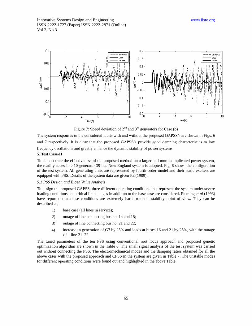
Figure 7: Speed deviation of 2nd
and 3rd
generators for Case (b)
The system responses to the considered faults with and without the proposed GAPSS’s are shown in Figs. 6
and 7 respectively. It is clear that the proposed GAPSS’s provide good damping characteristics to low
frequency oscillations and greatly enhance the dynamic stability of power systems.
5. Test Case-II
To demonstrate the effectiveness of the proposed method on a larger and more complicated power system,
the readily accessible 10-generator 39-bus New England system is adopted. Fig. 6 shows the configuration
of the test system. All generating units are represented by fourth-order model and their static exciters are
equipped with PSS. Details of the system data are given Pai(1989).
5.1 PSS Design and Eigen Value Analysis
To design the proposed GAPSS, three different operating conditions that represent the system under severe
loading conditions and critical line outages in addition to the base case are considered. Fleming et al (1993)
have reported that these conditions are extremely hard from the stability point of view. They can be
described as;
1) base case (all lines in service);
2) outage of line connecting bus no. 14 and 15;
3) outage of line connecting bus no. 21 and 22;
4) increase in generation of G7 by 25% and loads at buses 16 and 21 by 25%, with the outage
of line 21–22.
The tuned parameters of the ten PSS using conventional root locus approach and proposed genetic
optimization algorithm are shown in the Table 6. The small signal analysis of the test system was carried
out without connecting the PSS. The electromechanical modes and the damping ratios obtained for all the
above cases with the proposed approach and CPSS in the system are given in Table 7. The unstable modes
for different operating conditions were found out and highlighted in the above Table.

Innovative Systems Design and Engineering www.iiste.org
ISSN 2222-1727 (Paper) ISSN 2222-2871 (Online)
Vol 2, No 3
66
Figure 8: New England 10 generator 39 bus system
It is clear that these electromechanical modes are poorly damped and some of them are unstable. Here 30
parameters are optimized namely, iii and T , TK 31 ; i=1,2,3,..10. The time constant wT is set to be 10. In
this study 0 and 0 are chosen to be -1.0 and 0.2 respectively. Several values for weight ‘a’ were
tested. The results presented here are for a=10. From the eigenvalue analysis, for the base case it is clear
that all modes are well shifted in the D-stability region with min increased from 0.072% to 2.61% and
max from -0.0046 to -0.3012. Similarly for case-1, min increased from 1.35% to 2.62% and max
from -0.0826 to -0.3024 ; for case-2, min increased from 0.08% to 2.96% and max from -0.0051 to
-0.3260 ; and for case-3 min increased from 0.04% to 2.43% and max from -0.0023 to -0.2791.
Therefore, it is obvious that the critical mode eigen values have been shifted to the left in s-plane and the
system damping is greatly improved and enhanced with the proposed GAPSSs.
1
30
2
1 10
39
9
8
8
37
25
3
18
4
5
7
26 28 29
38 9
27
17 16
15
14
6
11
12
13
31
2
10
3
32
24
22
21
6
35
23
7
36
19
33 20
5 34
4

Innovative Systems Design and Engineering www.iiste.org
ISSN 2222-1727 (Paper) ISSN 2222-2871 (Online)
Vol 2, No 3
67
Table 6: Parameters of Conventional and Proposed GA method
CPSS Parameters GA PSS Parameters
K T1 T2 K T1 T2
10.4818
0.6799
0.2396
1.1531
17.0819
13.4726
4.3773
0.5709
1.6059
19.8488
0.6211
0.6185
0.5778
0.5727
0.6143
0.6163
0.5636
0.6099
0.5429
0.5027
0.1789
0.1796
0.1923
0.1940
0.1809
0.1803
0.1971
0.1822
0.2046
0.2210
32.200
3.6000
34.800
24.400
32.200
14.000
32.200
3.6000
21.800
8.8000
0.5333
0.8000
0.5333
0.5667
0.8667
0.7333
0.5333
0.5333
0.5333
0.9000
0.2333
0.3933
0.2067
0.1267
0.3400
0.3133
0.3667
0.4200
0.2600
0.2867
Table 7: Comparison of eigenvalues and damping ratios for different cases
Without PSS CPSS GA PSS
Base
Case
-1.1878 ±10.6655i, 0.1107
-0.3646 ± 8.8216i, 0.0413
-0.3063 ± 8.5938i, 0.0356
-0.2718 ± 8.1709i, 0.0332
-0.0625 ± 7.2968i, 0.0086
-0.1060 ± 6.8725i, 0.0154
0.2579 ± 6.1069i, -0.0422
0.0620 ± 6.1767i, -0.0100
0.0794 ± 3.9665i, -0.0200
-1.5226 ±11.7232i, 0.1288
-1.3326 ±11.2726i, 0.1174
-1.9859 ±11.1499i, 0.1753
-0.9837 ± 9.0350i, 0.1082
-0.5380 ± 8.5014i, 0.0632
-0.1568 ± 7.3758i, 0.0213
-1.0658 ± 7.2601i, 0.1452
-0.0046 ± 6.3800i, 0.0007
-1.2016 ± 4.5676i, 0.2544
-1.1509 ±11.4696i, 0.0998
-0.4693 ±11.4972i, 0.0408
-0.3012 ±11.5151i, 0.0261
-0.9554 ±10.1115i, 0.0941
-0.6069 ± 8.9271i, 0.0678
-1.0313 ± 7.9303i, 0.1290
-0.5381 ± 7.1383i, 0.0752
-3.5472 ± 2.9544i, 0.7684
-1.2658 ± 2.8107i, 0.4106
Case-1
-1.1888 ±10.6603i, 0.1108
-0.3642 ± 8.8221i, 0.0412
-0.3087 ± 8.5753i, 0.0360
-0.2727 ± 8.1706i, 0.0334
-0.0643 ± 7.2859i, 0.0088
-0.1000 ± 6.7243i, 0.0149
0.2997 ± 6.1030i, -0.0490
0.0824 ± 5.7423i, -0.0143
0.0844 ± 3.8066i, -0.0222
-1.5173 ±11.7109i, 0.1285
-1.3362 ±11.2695i, 0.1177
-1.9880 ±11.1547i, 0.1755
-0.9669 ± 9.0331i, 0.1064
-0.5240 ± 8.4869i 0.0616
-0.1593 ± 7.3687i, 0.0216
-0.0826 ± 6.1146i, 0.0135
-1.0081 ± 6.0958i, 0.1632
-1.9766 ± 6.0065i, 0.3126
-1.1545 ±11.4461i, 0.1004
-0.4779 ±11.4935i, 0.0415
-0.3024 ±11.5189i, 0.0262
-0.9581 ±10.1115i, 0.0943
-0.6022 ± 8.8041i, 0.0682
-1.2073 ± 7.9923i, 0.1494
-0.4442 ± 6.9509i, 0.0638
-1.2449 ± 2.6661i, 0.4231
-2.1581 ± 2.4042i, 0.6680

Innovative Systems Design and Engineering www.iiste.org
ISSN 2222-1727 (Paper) ISSN 2222-2871 (Online)
Vol 2, No 3
68
Case-2
-1.1686 ±10.6268i, 0.1093
-0.3413 ± 8.7548i, 0.0390
-0.3013 ± 8.4738i, 0.0355
-0.2575 ± 8.0464i, 0.0320
-0.0615 ± 7.3143i, 0.0084
0.1283 ± 6.1862i,
0.0207
0.0427 ± 6.0556i, -0.0070
0.2018 ± 5.8565i, -0.0344
0.1659 ± 3.7438i, -0.0443
-1.3152 ±11.2723i, 0.1159
-1.4305 ±11.2210i, 0.1265
-2.0125 ±11.0700i, 0.1789
-0.5674 ± 8.4623i, 0.0669
-0.7944 ± 8.1979i, 0.0964
-0.1547 ± 7.3961i, 0.0209
-0.0051 ± 6.3664i, 0.0008
-0.9179 ± 5.9988i, 0.1513
-0.9712 ± 3.5259i, 0.2656
-1.1550 ±11.3826i, 0.1010
-0.5047 ±11.4755i, 0.0439
-0.3348 ±11.3197i, 0.0296
-1.0116 ±10.0916i, 0.0997
-0.6046 ± 8.2732i, 0.0729
-1.3450 ± 7.0309i, 0.1879
-0.3260 ± 7.1950i, 0.0453
-1.1795 ± 2.8455i, 0.3829
-2.1806 ± 2.4528i, 0.6644
Case-3
-1.1645 ±10.6163i, 0.1090
-0.3256 ± 8.8902i, 0.0366
-0.2977 ± 8.4483i, 0.0352
-0.2587 ± 8.0346i, 0.0322
-0.0575 ± 7.3333i, 0.0078
0.1557 ± 6.1630i, -0.0253
0.0586 ± 6.0959i, -0.0096
0.2089 ± 5.6778i, -0.0368
0.2352 ± 3.6446i, -0.0644
-1.3405 ±11.3267i, 0.1175
-1.3380 ±11.2101i, 0.1185
-2.0206 ±11.0315i, 0.1802
-0.5650 ± 8.4482i, 0.0667
-0.7508 ± 8.1182i, 0.0921
-0.1506 ± 7.4154i, 0.0203
-0.0023 ± 6.3596i, 0.0004
-0.6910 ± 5.8629i, 0.1171
-0.7668 ± 3.3898i, 0.2206
-1.1638 ±11.3603i, 0.1019
-0.5379 ±11.4627i, 0.0469
-0.2791 ±11.4750i, 0.0243
-1.0219 ±10.0795i, 0.1009
-0.6143 ± 8.2200i, 0.0745
-1.3956 ± 6.9823i, 0.1960
-0.2836 ± 7.1579i, 0.0396
-1.1205 ± 2.8562i, 0.3652
-2.1899 ± 2.4765i, 0.6624
5.2 Nonlinear time domain simulation
To demonstrate the effectiveness of the PSSs tuned using the proposed multiobjective function over a wide
range of operating conditions, the following disturbance is considered for nonlinear time simulations.
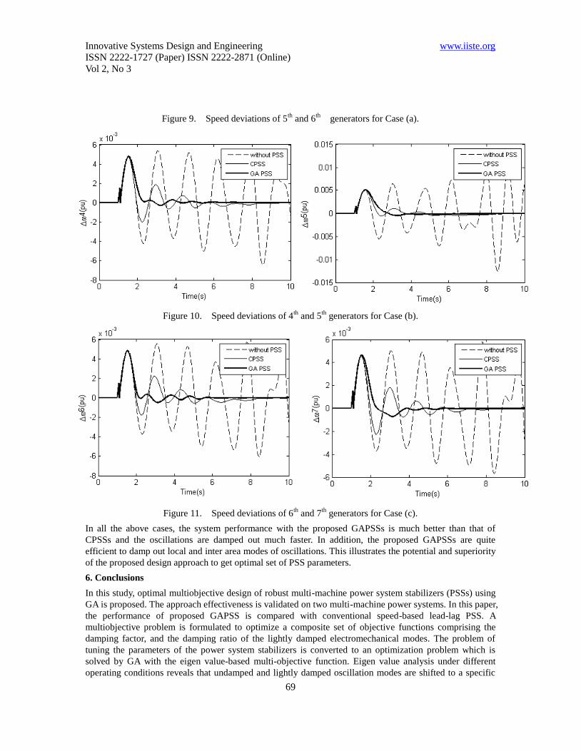
Case (a): A six-cycle three-phase fault, very near to the 14th bus in the line 4–14, is simulated. The fault is
cleared by tripping the line 4–14. The speed deviation of generators G5 & G6 are shown in Fig. 9.
Case (b): A six-cycle fault disturbance at bus 33 at the end of line 19-33 with the load at bus-25 doubled.
The fault is cleared by tripping the line 19-33 with successful reclosure after 1.0 s. Fig. 10 shows the
oscillations of 4th
and 5th
generators.
Case (c) Another critical five cycle three-phase fault is simulated very near to the 22nd bus in the line
22–35 with load at bus-21 increased by20%, in addition to 25th bus load being doubled as in Case(b). The
speed deviations of generators G7 & G8 are shown in Fig. 11.
Innovative Systems Design and Engineering www.iiste.org
ISSN 2222-1727 (Paper) ISSN 2222-2871 (Online)
Vol 2, No 3
69
Figure 9. Speed deviations of 5th
and 6th
generators for Case (a).
Figure 10. Speed deviations of 4th
and 5th
generators for Case (b).
Figure 11. Speed deviations of 6th
and 7th
generators for Case (c).
In all the above cases, the system performance with the proposed GAPSSs is much better than that of
CPSSs and the oscillations are damped out much faster. In addition, the proposed GAPSSs are quite
efficient to damp out local and inter area modes of oscillations. This illustrates the potential and superiority
of the proposed design approach to get optimal set of PSS parameters.
6. Conclusions
In this study, optimal multiobjective design of robust multi-machine power system stabilizers (PSSs) using
GA is proposed. The approach effectiveness is validated on two multi-machine power systems. In this paper,
the performance of proposed GAPSS is compared with conventional speed-based lead-lag PSS. A
multiobjective problem is formulated to optimize a composite set of objective functions comprising the
damping factor, and the damping ratio of the lightly damped electromechanical modes. The problem of
tuning the parameters of the power system stabilizers is converted to an optimization problem which is
solved by GA with the eigen value-based multi-objective function. Eigen value analysis under different
operating conditions reveals that undamped and lightly damped oscillation modes are shifted to a specific
Innovative Systems Design and Engineering www.iiste.org
ISSN 2222-1727 (Paper) ISSN 2222-2871 (Online)
Vol 2, No 3
70
stable zone in the s-plane. These results show the potential of GA algorithm for optimal settings of PSS
parameters. The nonlinear time-domain simulation results show that the proposed PSSs work effectively
over a wide range of loading conditions and system configurations.
References
Graham Rogers, “Power System Oscillations”, Springer, 1st edition, Kluwer academic publishers, 1999.
M.A. Pai, D.P.Sen Gupta, and K.R. Padiyar, “Small signal analysis of power systems”, 1st edition ,Narosa
Publishing House, 2004, pp.3.
Bikash Pal and Bakarko Chaudhuri, “Robust control in power systems”, Spinger, 2005, pp.5-6.
L. Rouco, “Coordinated design of multiple controllers for damping power system oscillations”,
International Journal of Electrical Power & Energy Systems, vol. 23, Issue 7, pp 517-530, October 2001.
Aboul-Ela M.E, Sallam A.A, McCalley J.D and Fouad A.A, “Damping controller design for power system
oscillations using global signals” Power Systems, IEEE Transactions on, vol. 11, Issue 2, May 1996 ,
pp.767 – 773.
Larsen E, Swann D, “Applying power system stabilizers”. IEEE Trans. PAS 1981;100(6):3017–3046.
Tse GT, Tso SK., “Refinement of conventional PSS design in multi-machine system by modal analysis”,
IEEE Trans. PWRS 1993;8(2):598–605.
Kundur P, Klein M, Rogers GJ, Zywno MS, “Application of power system stabilizers for enhancement of
overall system stability”, IEEE Trans. PWRS 1989;4(2):614–626.
Fleming RJ, Mohan MA, Parvatism K., “Selection of parameters of stabilizers in multi-machine power
systems”, IEEE Trans. PAS 1981; 100(5):2329–2333.
Abe S, Doi A, “A new power system stabilizer synthesis in multi-machine power systems”, IEEE Trans.
PAS 1983;102(12):3910–3918.
Arredondo JM. “Results of a study on location and tuning of power system stabilizers”, International
Journal Electrical Power and Energy Systems 1997;19(8):563–567.
Gooi HB, Hill EF, Mobarak MA, Throne DH, Lee TH, “Coordinated multi-machine stabilizer settings
without eigenvalue drift” IEEE Trans. PAS 1981;100(8):3879–3887.
Lefebvre S, “Tuning of stabilizers in multi-machine power systems”,IEEE Trans. PAS
1983;102(2):290–299.
Lim CM, Elangovan S, “Design of stabilizers in multi-machine power systems”, IEE Proceedings,
1985 ;132(3):146–153.
Chen CL, Hsu YY, “Coordinated synthesis of multi-machine power system stabilizer using an efficient
decentralized modal control (DMC) algorithm”, IEEE Trans. PWRS 1987;2(3):543–551.
Yu YN, Li Q, “Pole-placement power system stabilizers design of an unstable nine-machine system”, IEEE
Trans. PWRS 1990;5(2) pp:353– 358.
Y. L. Abdel-Magid, M. A. Abido, S. Al-Baiyat and A.H.Mantawy, “Simultaneous stabilization of
multi-machine power algorithms via genetic algorithms” IEEE Trans. Power Syst., vol. 14, 1999,
pp1428-1438
W.E.Schmitendorf, RW.Benson, Oshawa and S.Forrest, “ Using Genetic Algorithm For Controller
Design",Proceedings of AIAA Conference on the Guidance, Navigation and Control Hilton Head Island,
South Carolina, August 1992,pp757-761

This academic article was published by The International Institute for Science,
Technology and Education (IISTE). The IISTE is a pioneer in the Open Access
Publishing service based in the U.S. and Europe. The aim of the institute is
Accelerating Global Knowledge Sharing.
More information about the publisher can be found in the IISTE’s homepage:
http://www.iiste.org
The IISTE is currently hosting more than 30 peer-reviewed academic journals and
collaborating with academic institutions around the world. Prospective authors of
IISTE journals can find the submission instruction on the following page:
http://www.iiste.org/Journals/
The IISTE editorial team promises to the review and publish all the qualified
submissions in a fast manner. All the journals articles are available online to the
readers all over the world without financial, legal, or technical barriers other than
those inseparable from gaining access to the internet itself. Printed version of the
journals is also available upon request of readers and authors.
IISTE Knowledge Sharing Partners
EBSCO, Index Copernicus, Ulrich's Periodicals Directory, JournalTOCS, PKP Open
Archives Harvester, Bielefeld Academic Search Engine, Elektronische
Zeitschriftenbibliothek EZB, Open J-Gate, OCLC WorldCat, Universe Digtial
Library , NewJour, Google Scholar