Optimal BIOS Settings for High Performance Computing with ... · Optimal BIOS Settings for High...
28
By Jacob Liberman and Garima Kochhar High Performance Computing Engineering Dell Product Group 13 July 2009 Optimal BIOS Settings for High Performance Computing with PowerEdge 11G Servers A Dell Technical White Paper
Transcript of Optimal BIOS Settings for High Performance Computing with ... · Optimal BIOS Settings for High...

By Jacob Liberman and Garima Kochhar
High Performance Computing Engineering Dell Product Group
13 July 2009
Optimal BIOS Settings for High Performance Computing with PowerEdge 11G Servers A Dell Technical White Paper

Optimal BIOS Settings for High Performance Computing with PowerEdge 11G Servers
Page ii
THIS WHITE PAPER IS FOR INFORMATIONAL PURPOSES ONLY, AND MAY CONTAIN TYPOGRAPHICAL ERRORS AND TECHNICAL INACCURACIES. THE CONTENT IS PROVIDED AS IS, WITHOUT EXPRESS OR IMPLIED WARRANTIES OF ANY KIND.
© 2009 Dell Inc. All rights reserved. Reproduction of this material in any manner whatsoever without the express written permission of Dell Inc. is strictly forbidden. For more information, contact Dell.
Dell, the DELL logo, EqualLogic, PowerEdge, PowerConnect, OpenManage and the DELL badge are trademarks of Dell Inc.; Microsoft, Outlook, and Windows are either trademarks or registered trademarks of Microsoft Corporation in the United States and/or other countries. Intel, Core, Xeon, and Pentium are either registered trademarks or trademarks of Intel Corporation in the U.S. and other countries; Red Hat and Enterprise Linux are registered trademarks of Red Hat, Inc. in the United States and other countries.
Optimal BIOS Settings for High Performance Computing with PowerEdge 11G Servers
Table of Co.......................................................................................................... 3
ntents Introduction .........................
hitecture .......................................................................................................... 3 Intel Nehalem Arc
..................................................................................................... 5 Test Methodology .....................
Overview of 11G BIOS Options ..................................................................................................... 7
Node Interleaving
..................................................................................................................... 8
.................................................................................................................................... 7
Logical Processor ................
anagement Profile..................................................................................................................... 9 Power M
.............................................................................................................................................. 9 C‐States .......
Mode ............................................................................................................................................ 10 Turbo
Re ........... 10 sults ...............................................................................................................................
........................................................................................................................................... 11 Power ...........
Pe ................................................................................................................................ 12 rformance ...........
................................................................................................................... 12 Node Interleaving ...................
ing ................................................................................................................... 13 Simultaneous Multithread
C‐States .......................................................................................................................... 14 Turbo Mode and
En ............................................................................................................... 17 ergy Efficiency ....................
ement Profiles ..................................................................................................................... 17 Power Manag
...................................................................................................................... 18 BIOS Settings ........................
fficient Processors ...................................................................................................................... 19 Energy E
.................................................................................................................................... 21 Conclusion
................................................................................................ 22 References ....................................
Ap ary ................................................................................................ 23 pendix A– Findings Summ
ement Profiles ................................................................................................................. 23 Power Manag
................................................................................................................................... 23 Performance ........
...................................... 23 Energy Efficiency .............................................................................................
options from Linux command line .................................. 25 Appendix B – DTK to modify BIOS
Appendix C – Benchmark versions ............................................................................................ 26
Page 1
Optimal BIOS Settings for High Performance Computing with PowerEdge 11G Servers
Executive Summary
Dell’s 11th generation dual‐socket PowerEdge® servers feature Intel® Xeon® 5500 series processors based on the latest Intel micro‐architecture, codenamed Nehalem. This micro‐architecture provides features that can be controlled by the server BIOS and are designed to improve performance and energy efficiency across a wide range of server workloads. The 11G servers also introduce BIOS‐level, demand‐based power management (DBPM) profiles beyond those specified by the micro‐architecture.
In this paper, BIOS features and DBPM profiles are tested to provide the optimal settings for high performance computing (HPC) environments. The performance impact and power consumption of various BIOS settings and DBPM profiles are compared across clusters running several open source and commercial applications, and best practices are recommended from the measured results. The paper oncludes with recommendations for maximizing system performance and energy efficiency. c
Page 2
Optimal BIOS Settings for High Performance Computing with PowerEdge 11G Servers
Introduction Dell’s 11th Generation (11G) dual‐socket PowerEdge servers1 include the Intel Xeon 5500 series processors based on the latest Intel micro‐architecture, codenamed Nehalem. Unlike Intel’s previous x86 platforms, the Intel Xeon 5500 series features a memory controller integrated directly on the processor. Remote memory is accessed over the QuickPath Interconnect (QPI), a high‐speed bus between processor sockets. QPI eliminates the memory bandwidth contention inherent to legacy front side bus (FSB) architectures; each processor has faster access to its local memory, making Nehalem a non‐uniform memory access (NUMA) architecture. Beyond the architectural enhancements, the 5500 series processors introduce new features that are designed to improve performance and energy efficiency. This paper describes these features, and their benefits in high performance computing cluster (HPCC) contexts.
HPCC is an approach to high performance computing where commodity servers are linked together using high‐speed networking equipment in order to achieve supercomputer‐like performance. Over the past 10 years, computational clusters have emerged as the de facto standard for HPC applications due to the extraordinary price for performance they can deliver2. 11G servers combine Intel Xeon 5500 series processors, Gen 2 PCIe support, and an energy efficient chassis that makes them suitable building blocks for HPCC.
This paper introduces the Intel Xeon 5500 processor, and describes the BIOS features and DBPM profiles offered with 11G servers. It also details the test methodology, and shares the performance impact of the various BIOS settings across several typical HPC workloads. The paper concludes with BIOS setting recommendations for maximizing performance, energy efficiency, and for maximizing performance within power constraints.
HPC workloads require balanced architectures, where no single subsystem dominates the execution time. The guidelines presented here may be inappropriate for enterprise workloads, such as databases or mail servers that are typically I/O bound.
Intel Nehalem Architecture Intel’s Nehalem micro‐architecture is the successor to the Penryn micro‐architecture. Nehalem‐EP features two processor sockets that support the Intel Xeon 5500 series processors. The 5500 series processors are similar to the 5400 series in several ways:
• They share the same 45 nm manufacturing process
• They both have four cores per socket, and support version 4 streaming SIMD extensions (SSE) for performing scalar and packed‐floating point instructions.
• The 5500 series clock frequencies are similar to previous generations. At the time of authoring this paper, the top frequency processor qualified for 11G servers is 2.93 GHz. 3.16 GHz was the highest frequency 5400 series processor qualified for the 10th Generation (10G) Dell PowerEdge servers.
Page 3

Optimal BIOS Settings for High Performance Computing with PowerEdge 11G Servers
Although 5500 series processors are similar to the 5400 series in many ways, they do have fundamental differences. The 5500 has a new cache structure; the 5400 series could allocate up to 6MB of shared L2 cache to a single core where as the 5500 series has 256KB of dedicated L2 cache per core, and an 8MB fully‐inclusive L3 cache shared across all cores in a socket.
The biggest difference between Nehalem and previous architectures is the memory subsystem. The Xeon 5400 series processor family supported either 1333 or 1600 MHz front side bus (FSB) access to a shared memory controller. With the new architecture, Intel abandoned the legacy FSB architecture in favor of DDR‐3 memory controllers integrated directly onto the processor. Integrated memory controllers provide faster access to local memory, and eliminate the contention inherent to FSB architectures supporting multi‐core processors over a shared bus. Figure 1 is a block diagram of an Intel Nehalem‐EP processor.
Figure 1 – Xeon 5500 Processor Block Diagram
Each Nehalem‐EP memory controller has three DDR‐3 channels for memory operations. Dell 11G dual‐socket PowerEdge servers support a maximum of two or three DIMMS per channel (DPC), depending on the server model. The PowerEdge R710 and M710 servers support up to 3 DPC resulting in nine DIMMs per processor socket, or eighteen DIMMs per server. The R610 and M610 support up to 2 DPC resulting in six DIMMs per memory socket, or twelve DIMMs per server.
Page 4

Optimal BIOS Settings for High Performance Computing with PowerEdge 11G Servers
Processor cores access local memory directly through the integrated memory controller. Nehalem features QPI, a high‐speed bus between the processor sockets that supports remote memory access and connects to the shared I/O controller. Figure 2 is a block diagram of the dual socket Nehalem‐EP architecture.
Figure 2 – Nehalem‐EP Architecture Block Diagram
The local memory accesses through the integrated memory controller are faster than the remote accesses using the QPI links in the Nehalem architecture. The QPI link speed varies with the processor frequency bin, as described in Table 3.
Test Methodology Beyond the architectural enhancements described in the previous section, Nehalem also introduces BIOS features that are intended to improve energy efficiency and performance, and the 11G servers include additional power management features. This paper quantifies the impact of these features in order to derive guidelines for maximizing performance and energy efficiency in an HPC context.
Single servers and clusters were benchmarked using a suite of typical HPC applications and micro‐benchmarks. Micro‐benchmarks measure the performance of independent subsystems and are idealized workloads that are useful in identifying the maximum impact of a feature on a particular subsystem. Cluster‐level applications were used to assess the real world impact of the BIOS settings and memory profiles. A mix of open source and commercial applications were selected for the study. The benchmarks and applications are listed in Table 1, and benchmark details are provided in Appendix C – Benchmark versions.
Page 5

Optimal BIOS Settings for High Performance Computing with PowerEdge 11G Servers
Table 1 – Benchmarks and Applications Used
Description Type Benchmark
Threaded memory bandwidth test Memory micro‐benchmark Stream
lat_mem_rd Memory latency test, idle array chasing Memory micro‐benchmark from LMBench
Threaded matrix multiplication routine CPU micro‐benchmark DGEMM
HPL Distributed floating point benchmark CPU and communication benchmark
Computational fluid dynamics Commercial clustered applicationFluent
Ansys Structural mechanics Commercial clustered application
Reservoir simulation Commercial clustered applicationECLIPSE
WRF Climate modeling Open source clustered application
Lower‐upper decomposition, physical systems Open source clustered synthetic kernelLU
Nehalem’s BIOS features are not only intended to boost performance, but also to save power. For that reason, the benchmark performance results are complemented by measuring power consumption; for HPC applications, performance improvements often require increased power consumption. The power data are used in conjunction with application performance data in order to quantify the power and performance tradeoffs associated with various BIOS settings. Energy efficiency is calculated as Performance/Power or performance per watt. “Rating” – or the number of application runs that can be completed in one day – provides a common performance measurement unit across benchmarks. An application’s rating equals the number of seconds in a day divided by the application run time in seconds. All results are drawn from performance data gathered in Dell’s HPCC engineering lab. The test cluster configuration is described in Table 2; specific configuration details for each benchmark are also noted where appropriate.
Table 2 – Test cluster configuration
Component Description
SERVERS: Dell PowerEdge R610, Dell PowerEdge M610 (16) in a PowerEdge M1000e chassis
SERVER BIOS: 1.1.4
PROCESSORS: Intel Xeon X5550, Intel Xeon X5570, Intel Xeon E5540
MEMORY: 6 x 4GB 1333 MHz RDIMM, 6 x 4GB 1066 MHz RDIMM
STORAGE: Dell SAS 6iR controller, 2 x 73GB 10k RPM SAS hard drives, RAID 1 on M610
Dell Perc6i controller, 2 X 73GB 15k RPM SAS hard drives, RAID 0 on R610
INTERCONNECT: InfiniBand ‐ Mellanox MTH MT26428 [ConnectX IB QDR, Gen‐2 PCIe]
IB SWITCH: Mellanox 3601Q QDR blade chassis I/O switch module
GbE NETWORK: Broadcom BCM5709
GbE switch: PowerConnect™ M6220 chassis I/O switch module, PowerConnect 6248 rack switch
Page 6

Optimal BIOS Settings for High Performance Computing with PowerEdge 11G Servers
ClusterCorp Rocks+ 5.1 for Dell*3SOFTWARE:
OS: Red Hat Enterprise Linux 5.3 x86_64 (2.6.18‐128.el5 kernel)
IB STACK: Mellanox OFED 1.4
*This product includes software developed by the Rocks Cluster Group at the San Diego Supercomputer Center at the University of California, San Diego and its contributors.
Overview of 11G BIOS Options This section describes the 11G BIOS options examined in this study. Although 11G servers support additional BIOS settings, this study focused on the settings and profiles applicable to an HPC context; including node interleaving, logical processor, C‐states, Turbo mode, and power management profiles. This section includes descriptions and steps for enabling each option, as well as additional background information and the performance measurements necessary for understanding the study results.
Node Interleaving Nehalem has a NUMA architecture where the processors have asymmetric access to local and remote memory. Table 3 lists the theoretical bandwidth for local and remote memory accesses4, 5. On the 5500 series, the processor clock frequency determines the maximum bandwidth of the integrated memory controller.
Table 3 – Theoretical Memory Bandwidth
QPI Link (GT/s) Memory Controller (GB/s) QPI Link Speed (GB/s)CPU Frequency (GHz)
6.40 31.99 25.60 2.66 to 3.20
2.26 to 2.53 5.86 25.58 23.44
4.80 19.20 19.201.86 to 2.13
The theoretical values in Table 3 define the boundaries for local and remote memory operations; however, achievable performance is always less than the maximum defined by theoretical performance. Figure 3 shows the bandwidth and latency differences between local and remote memory operations as measured by the STREAM and lat_mem_rd micro‐benchmarks.
Page 7

Optimal BIOS Settings for High Performance Computing with PowerEdge 11G Servers
0
2000
4000
6000
8000
10000
12000
LOCAL INTERLEAVE REMOTE
MB/s
NUMA Policy
Stream ‐‐ 1 thread
Copy Scale Add Triad
0
20
40
60
80
100
120
‐10.0
‐6.4
‐5.3
‐4.4
‐3.5
‐2.7
‐1.8
‐1.0
‐0.1 0.8
1.7
2.6
3.5
4.3
5.2
6.0
6.9
7.8
Nanosecon
ds
Log 2 MB
Memory Latency
LOCAL REMOTE INTERLEAVE
Figure 3 – Memory latency and bandwidth accessing local, remote memory for a PowerEdge R610, Dual Intel Xeon X5550, 6 * 4GB 1333 MHz RDIMMS.
Figure 3 illustrates that local memory operations have approximately 40% higher bandwidth and lower latency than remote memory operations. Since remote memory accesses incur a performance penalty associated with traversing the QPI links, 11G servers offer node interleaving, a third memory access pattern, that partially offsets the penalty associated with remote memory accesses by striping data across both memory controllers. Figure 3 shows that node interleaving performance falls between local and remote performance for both memory bandwidth and latency.
To enable node interleaving in the server BIOS, select F2 on the server boot up screen and then select the following options:
Memory Settings Node Interleaving, Values = Disabled (default), Enabled
A fuller explanation of node interleaving and the Intel Xeon 5500 memory subsystem is available in the Dell technical whitepaper describing the memory selection guidelines for HPC.
Logical Processor The logical processor feature is based on Intel’s simultaneous multithreading (SMT) technology. SMT enabled systems appear to the operating system as having twice as many processor cores as they actually do by ascribing two “logical” cores to each physical core. SMT can improve performance by assigning threads to each logical core; logical cores execute their threads by sharing the physical cores’ resources.
To enable the logical processor feature in the server BIOS, select F2 on the server boot up screen and then select the following options:
Processor Settings Logical Processor, Values=Enabled (default), Disabled
Page 8
Optimal BIOS Settings for High Performance Computing with PowerEdge 11G Servers
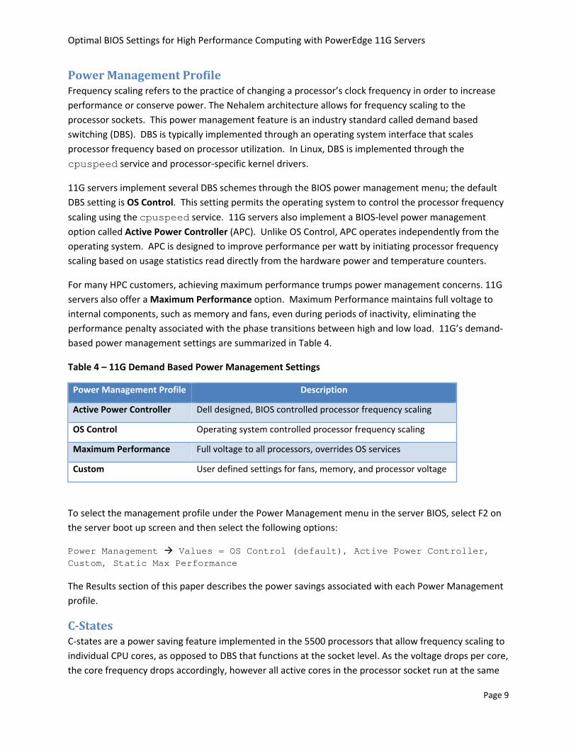
Power Management Profile Frequency scaling refers to the practice of changing a processor’s clock frequency in order to increase performance or conserve power. The Nehalem architecture allows for frequency scaling to the processor sockets. This power management feature is an industry standard called demand based switching (DBS). DBS is typically implemented through an operating system interface that scales processor frequency based on processor utilization. In Linux, DBS is implemented through the cpuspeed service and processor‐specific kernel drivers.
11G servers implement several DBS schemes through the BIOS power management menu; the default DBS setting is OS Control. This setting permits the operating system to control the processor frequency
scaling using the cpuspeed service. 11G servers also implement a BIOS‐level power management option called Active Power Controller (APC). Unlike OS Control, APC operates independently from the operating system. APC is designed to improve performance per watt by initiating processor frequency scaling based on usage statistics read directly from the hardware power and temperature counters.
For many HPC customers, achieving maximum performance trumps power management concerns. 11G servers also offer a Maximum Performance option. Maximum Performance maintains full voltage to internal components, such as memory and fans, even during periods of inactivity, eliminating the performance penalty associated with the phase transitions between high and low load. 11G’s demand‐based power management settings are summarized in Table 4.
Table 4 – 11G Demand Based Power Management Settings
Power Management Profile Description
Active Power Controller Dell designed, BIOS controlled processor frequency scaling
OS Control Operating system controlled processor frequency scaling
Maximum Performance Full voltage to all processors, overrides OS services
Custom User defined settings for fans, memory, and processor voltage
To select the management profile under the Power Management menu in the server BIOS, select F2 on the server boot up screen and then select the following options:
Power Management Values = OS Control (default), Active Power Controller, Custom, Static Max Performance
The Results section of this paper describes the power savings associated with each Power Management profile.
CStates C‐states are a power saving feature implemented in the 5500 processors that allow frequency scaling to individual CPU cores, as opposed to DBS that functions at the socket level. As the voltage drops per core, the core frequency drops accordingly, however all active cores in the processor socket run at the same
Page 9

Optimal BIOS Settings for High Performance Computing with PowerEdge 11G Servers
frequency. The different C‐states provide information on whether the cores are active or inactive. Several C‐states are listed in Table 5.
Table 5 – Example C‐States
State DescriptionC‐State
Active Active state ‐ instructions are not being executed by the core. C0
C1 Active Active state ‐ the core is active but no instructions are executed.
Inactive Idle state ‐ the core is inactive and core caches are flushed. C3
C6 Inactive Power gates reduce power consumption close to 0, caches are flushed.
The 5500 series processors support many C‐states whose usage models differ across hardware vendors.
Turbo Mode Turbo mode, also referred to as Turbo Boost6, allows the processor cores to run faster than their base operating frequency under certain conditions. If the processor is operating below the rated power and thermal limits, the Turbo mode can provide a performance boost by raising the CPU clock rate.
To enable Turbo mode in the server BIOS if the processor supports it, select F2 on the server boot up screen and then select the following options:
Processor Settings Turbo Mode, Values=Enabled (default), Disabled
The maximum frequency that a processor can reach depends on the number of active cores in the system, and also varies based on the processor model number7. For example, the Intel Xeon X5550 processor has a base frequency of 2.66 GHz. This processor has a Turbo boost rating of 2/2/3/3. This rating designates the number of additional 133 MHz frequency steps available to the processor when 4, 3, 2, or 1 cores are active. For example, the Xeon 5500 can step up two frequency steps when all four cores are active, raising the frequency from 2.66 to 2.93 GHz. All active cores within the processor will operate at the same frequency.
Results This section describes the results of the power consumption, performance, and energy efficiency tests conducted on the clusters and single servers. The section begins with a comparison of idle power consumption across the power management profiles. Next, the performance impact of various BIOS settings are described along with best practices for maximizing performance. The results section concludes with an energy efficiency study that quantifies the relationship between improved performance and increased power consumption.
Page 10

Optimal BIOS Settings for High Performance Computing with PowerEdge 11G Servers
Power As clusters continue to grow, power consumption has become one of the primary cluster design consideration. The infrastructure costs associated with powering and cooling can quickly erode a cluster’s favorable economics. Additionally, many clusters are not fully utilized at all times; interactive clusters – where users submit jobs without a scheduler – have periods of inactivity. For these clusters, minimizing power consumption when they are idle is an important consideration.
0.80
0.90
1.00
1.10
Relative Id
le Pow
er
Time
Idle Power Consumption Across Profiles
APC MaxPerf OsCtl w/ cpuspeed
Figure 4 – Relative idle power consumption by the power management profile on a 16‐node PowerEdge M610 cluster, each with Dual Intel Xeon X5570, 6 x 4GB 1333 MHz RDIMMS Figure 4 compares the idle power consumption across the power management profiles supported by 11G servers; Turbo mode, C‐states, node interleaving and SMT BIOS options were disabled. This chart demonstrates that all three power profiles consumed about the same amount of power while the system was idle. For idle clusters, any power management profile is acceptable. Therefore, power profile selection should be based on the power usage under load; these data are described in the following sections of this paper.
Figure 5 demonstrates that by enabling C‐states, there are substantial additional power savings when systems are idle. This chart compares the idle power consumption of a 16‐node cluster across power profiles. The height of the bar shows the amount of power saved when C‐states are enabled versus when C‐states are disabled for each power profile; Turbo mode, node interleaving, and logical processor were disabled during this test.
Page 11

Optimal BIOS Settings for High Performance Computing with PowerEdge 11G Servers
26% 27%32%
0%
10%
20%
30%
40%
Power savings vs C‐states disab
led
Idle Power Saving with C‐states Enabled
APC MaxPerf OsCtl w/ cpuspeed
Figure 5 – Idle power savings with C‐states enabled on a 16‐node PowerEdge M610 cluster, each with Dual Intel Xeon X5570, 6 x 4GB 1333 MHz RDIMMS
This study demonstrates that enabling C‐states results in up to 32% idle power savings across the cluster. Therefore, C‐States should be enabled to minimize power consumption on idle or interactive clusters.
Performance The previous section described the best practices for minimizing idle power consumption with HPC clusters. This section describes the BIOS settings for maximizing performance. The final results section, Energy Efficiency, will present the best practices for improving performance per watt.
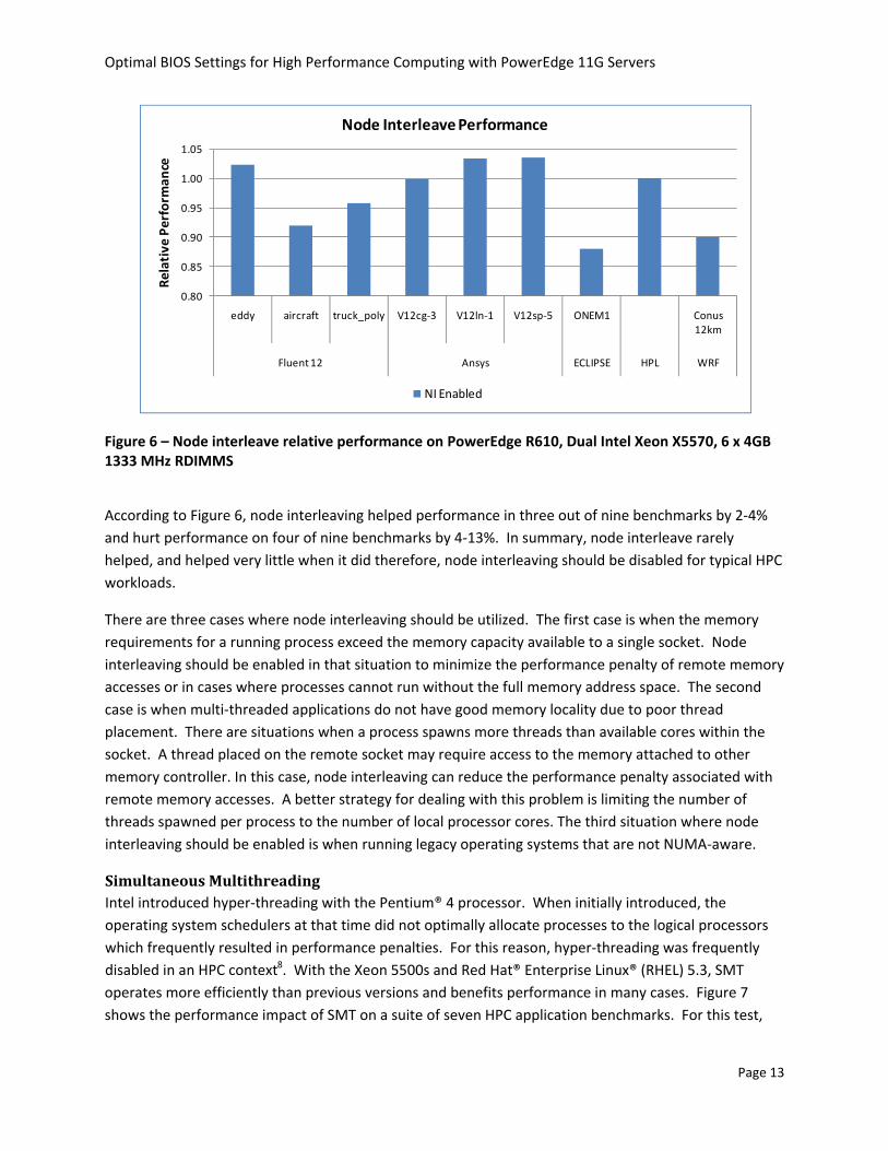
Node Interleaving For this study, single node application performance was measured across nine benchmarks with node interleaving enabled and then disabled, in order to understand the impact of node interleaving on HPC application performance. The results of this study are displayed in Figure 6. A bar higher than 1.0 indicates the amount that performance was improved when node interleaving was enabled versus when it was disabled.
Page 12
Optimal BIOS Settings for High Performance Computing with PowerEdge 11G Servers
0.80
0.85
0.90
0.95
1.00
1.05
eddy aircraft truck_poly V12cg‐3 V12ln‐1 V12sp‐5 ONEM1 Conus 12km
Fluent 12 Ansys ECLIPSE HPL WRF
Relative
Perform
ance
Node Interleave Performance
NI Enabled
Figure 6 – Node interleave relative performance on PowerEdge R610, Dual Intel Xeon X5570, 6 x 4GB 1333 MHz RDIMMS
According to Figure 6, node interleaving helped performance in three out of nine benchmarks by 2‐4% and hurt performance on four of nine benchmarks by 4‐13%. In summary, node interleave rarely helped, and helped very little when it did therefore, node interleaving should be disabled for typical HPC workloads.
There are three cases where node interleaving should be utilized. The first case is when the memory requirements for a running process exceed the memory capacity available to a single socket. Node interleaving should be enabled in that situation to minimize the performance penalty of remote memory accesses or in cases where processes cannot run without the full memory address space. The second case is when multi‐threaded applications do not have good memory locality due to poor thread placement. There are situations when a process spawns more threads than available cores within the socket. A thread placed on the remote socket may require access to the memory attached to other memory controller. In this case, node interleaving can reduce the performance penalty associated with remote memory accesses. A better strategy for dealing with this problem is limiting the number of threads spawned per process to the number of local processor cores. The third situation where node interleaving should be enabled is when running legacy operating systems that are not NUMA‐aware.
Simultaneous Multithreading Intel introduced hyper‐threading with the Pentium® 4 processor. When initially introduced, the operating system schedulers at that time did not optimally allocate processes to the logical processors which frequently resulted in performance penalties. For this reason, hyper‐threading was frequently disabled in an HPC context8. With the Xeon 5500s and Red Hat® Enterprise Linux® (RHEL) 5.3, SMT operates more efficiently than previous versions and benefits performance in many cases. Figure 7 shows the performance impact of SMT on a suite of seven HPC application benchmarks. For this test,
Page 13

Optimal BIOS Settings for High Performance Computing with PowerEdge 11G Servers
SMT was enabled in the BIOS and applications were run with a number of processes equal to the logical cores in the system; the performance of SMT enabled is compared to when SMT is turned off. A value higher than 1.0 indicates the amount that SMT helped performance.
0.40
0.60
0.80
1.00
1.20
eddy aircraft truck_poly V12cg‐2 V12ln‐1 V12sp‐5 Conus 12km
Fluent Ansys WRF
Performan
ce Relative to SMT disabled
Logical Processor Performance
SMT enabled ‐ 16 threads
Figure 7 – Logical processor performance relative to logical processor disabled on PowerEdge R610, Dual Intel Xeon X5570, 6 x 4GB 1333 MHz RDIMMS
This chart shows that enabling SMT had mixed results. SMT helped performance on two test cases – Fluent truck_poly and Ansys V12ln‐1 – to the order of ~7 to 10%. There were several cases where SMT hurt performance, including Ansys V12sp‐5, whose performance fell by 11%. In other cases the results were inconclusive. SMT did not help performance on five workloads. Therefore, in order to maximize performance on HPC workloads, it is recommended that the performance impact of SMT be tested on a per application basis, and enabled or disabled as necessary.
Turbo Mode and CStates Turbo mode allows processor cores to run faster than their base operating frequency. This section describes the performance advantage associated with enabling Turbo mode. Although Turbo mode does not require that C‐states be enabled, Turbo mode is opportunistic and the system is more likely to operate in Turbo mode when C‐states are enabled. This is probably because when C‐states are enabled, the system has a larger thermal power envelope in which to operate. Figure 8 shows the CPU frequency of a Turbo‐capable processor during a CPU intensive benchmark with Turbo mode enabled and disabled.
Page 14

Optimal BIOS Settings for High Performance Computing with PowerEdge 11G Servers
2600
2700
2800
2900
3000
3100
3200Processor MHz
Time ‐‐‐>
Turbo + Cstates + Max Perf
2600
2700
2800
2900
3000
3100
3200
Processor MHz
Time ‐‐‐>
Max Perf
Figure 8 – CPU frequency with Turbo mode on PowerEdge R610, Dual Intel Xeon X5550, 6 x 4GB 1333 MHz RDIMMs
With Turbo mode and C‐states enabled, the core frequency varies between 2.66 GHz and 2.93 GHz; without Turbo mode, the processor frequency does not vary. From the diagram it is clear that the performance improvement that are seen during this benchmark run when Turbo mode is enabled are indeed due to the increased frequency that Turbo provides. Therefore, to take advantage of Turbo mode, enable Turbo mode in the BIOS. To maximize the chances of entering a Turbo mode, C‐states should be enabled as well. The power management profile can be set to any of the available options. With the OS Control Power Management profile, the Linux cpuspeed service must be enabled in order to take advantage of Turbo mode with C‐states. It is a common misconception that Turbo mode requires power headroom created by idle cores to boost performance. It is important to note that Turbo mode can boost performance even when all cores are fully utilized.
Figure 9 plots the performance of a 16‐node cluster running four HPC workloads across two interconnects. The graph shows results with Turbo mode enabled relative to it being disabled for each interconnect. A value higher than 1.0 means that Turbo mode improved performance by the corresponding amount on that particular interconnect. For these tests, C‐states were enabled and the power profile was set to OS Control; node interleaving and SMT were disabled.
Page 15

Optimal BIOS Settings for High Performance Computing with PowerEdge 11G Servers
IB
IB IBIB
GbEGbE
GbEGbE
0.96
0.98
1.00
1.02
1.04
1.06
1.08
1.10
ECLIPSE ‐ FOURMILL FLUENT ‐truck_poly_14m
LU ‐ class D WRF ‐ Conus 12kmPerformance with
Turbo
on relativ
e to Turbo
off
(highe
r is be
tter)
Performance gains with Turbo Mode
Figure 9 – Performance gains with Turbo mode enabled across cluster workloads and interconnects on 16‐node PowerEdge M610 cluster, each with dual Intel Xeon X5570, 6 x 4GB 1333 MHz RDIMMS
Figure 9 shows that enabling Turbo mode and C‐states helps performance 2 to 8% with the InfiniBand interconnect. For gigabit Ethernet, Turbo mode helped ECLIPSE, LU, and WRF by 1‐5% but did not help Fluent. The 2% drop in Fluent performance with Turbo over gigabit Ethernet is within the variation for this benchmark and, so the conclusion is that Turbo mode does not help Fluent over gigabit Ethernet. The gains seen with Turbo over gigabit Ethernet are lower than those seen over InfiniBand. It is likely that the communication overhead of gigabit Ethernet overshadows some of the performance gains associated with Turbo mode. Turbo provides a greater benefit to clusters with high speed interconnects. For maximum performance on HPC workloads, Turbo mode and C‐states should be enabled.
Although the C‐states feature is primarily intended to lower power consumption, Figure 10 demonstrates the relationship between C‐states and performance. C‐states can help performance when used in conjunction with Turbo mode, but there are situations where enabling C‐states can harm performance. With C‐states enabled, the CPU power envelope and heat dissipation are continually polled in order to initiate state transitions. This polling and the associated C‐state transitions can raise memory and interconnect latency, harming performance on latency bound applications. Figure 10 demonstrates the MPI latency increase associated with C‐state transitions when running the OSU MPI latency micro‐benchmark.
Page 16

Optimal BIOS Settings for High Performance Computing with PowerEdge 11G Servers
Figure 10 – Latency overhead from C‐state transitions on two PowerEdge R610, each with dual Intel Xeon X5570, 6 x 4GB 1333 MHz RDIMMS
0%
20%
40%
60%
80%
100%
0 1 2 3 4 5 6 7 8 9 10 11 12 13 14 15 16 17 18 19 20 21 22
Performance Overhead
Message Size (Log2 Bytes)
C‐States Impact on MPI Latency
IB
GBE
Figure 10 shows that enabling C‐states results in MPI latency increase of up to 20% for InfiniBand and 12% for gigabit Ethernet communication. For this reason, enabling C‐states may not be appropriate for latency‐dependent HPC workloads, such as real‐time trading applications used in financial services.
Energy Efficiency The previous sections recommended BIOS settings and power management profiles for reducing power consumption while the system is idle and maximizing application performance. This section will describe the best practices for maximizing energy efficiency. Optimizing energy efficiency means finding the optimal balance between performance and power consumption. Energy efficiency is typically measured as performance divided by power. For the purposes of this study, all application performance results were converted to a ‘rating’ that specifies the number of times the application could be run per day; a lower run time translates to a higher rating.
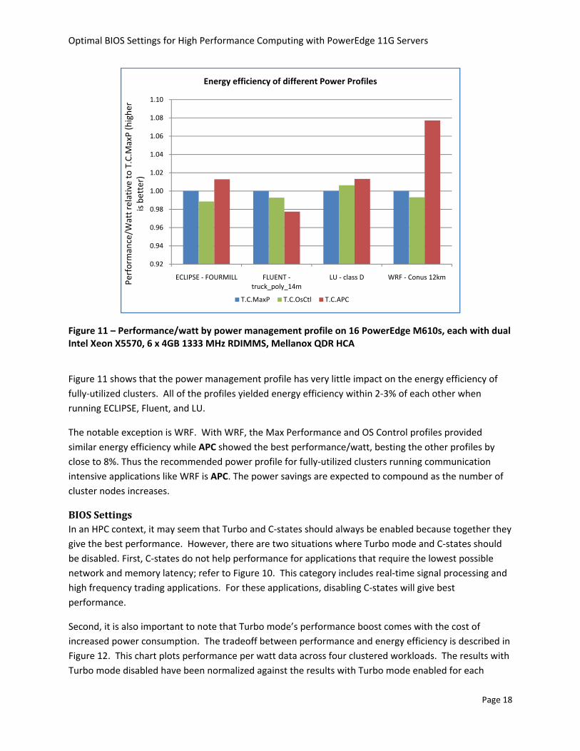
Power Management Profiles The Power section of this paper showed the reduced idle power consumption associated with enabling C‐states across power management profiles. This study compares the energy efficiency of the power management profiles across a fully utilized 16‐node cluster running four HPC workloads. Figure 11 graphs the energy efficiency of each power management profile relative to the Max Performance profile. A value higher than 1.0 means that the energy efficiency of the profile in question exceeds that of the Max Performance profile by the indicated value. For these tests, Turbo and C‐states were enabled and node interleaving and SMT were disabled.
Page 17
Optimal BIOS Settings for High Performance Computing with PowerEdge 11G Servers
0.92
0.94
0.96
0.98
1.00
1.02
1.04
1.06
1.08
1.10
ECLIPSE ‐ FOURMILL FLUENT ‐truck_poly_14m
LU ‐ class D WRF ‐ Conus 12kmPerformance/W
att relative to T.C.M
axP (highe
r is better)
Energy efficiency of different Power Profiles
T.C.MaxP T.C.OsCtl T.C.APC
Figure 11 – Performance/watt by power management profile on 16 PowerEdge M610s, each with dual Intel Xeon X5570, 6 x 4GB 1333 MHz RDIMMS, Mellanox QDR HCA
Figure 11 shows that the power management profile has very little impact on the energy efficiency of fully‐utilized clusters. All of the profiles yielded energy efficiency within 2‐3% of each other when running ECLIPSE, Fluent, and LU.
The notable exception is WRF. With WRF, the Max Performance and OS Control profiles provided similar energy efficiency while APC showed the best performance/watt, besting the other profiles by close to 8%. Thus the recommended power profile for fully‐utilized clusters running communication intensive applications like WRF is APC. The power savings are expected to compound as the number of cluster nodes increases.
BIOS Settings In an HPC context, it may seem that Turbo and C‐states should always be enabled because together they give the best performance. However, there are two situations where Turbo mode and C‐states should be disabled. First, C‐states do not help performance for applications that require the lowest possible network and memory latency; refer to Figure 10. This category includes real‐time signal processing and high frequency trading applications. For these applications, disabling C‐states will give best performance.
Second, it is also important to note that Turbo mode’s performance boost comes with the cost of increased power consumption. The tradeoff between performance and energy efficiency is described in Figure 12. This chart plots performance per watt data across four clustered workloads. The results with Turbo mode disabled have been normalized against the results with Turbo mode enabled for each
Page 18

Optimal BIOS Settings for High Performance Computing with PowerEdge 11G Servers
benchmark. A value above 1.0 means that the cluster had higher energy efficiency with Turbo mode disabled. Energy efficiency consists of two components –performance and the power. Improved energy efficiency can come from decreased power usage, increased performance or both. In Figure 12, the text in the bars show the loss in performance from disabling Turbo, and the power savings that comes from disabling Turbo. For example, with ECLIPSE disabling Turbo caused a 2% drop in performance, but a 21% power saving as compared to having Turbo enabled. That translated to an 18% improvement in energy efficiency with Turbo disabled, as compared to having Turbo enabled. In this experiment, C‐states were enabled, the power profile was set to OS Control, node interleaving and SMT were disabled, and the InfiniBand interconnect was used.
‐2% Perf
+ 21
% Pow
er
‐6% Perf
+20%
Pow
er
‐5% Perf
+ 14
% Pow
er
‐8% Perf
+ 12
% Pow
er
1.00
1.02
1.04
1.06
1.08
1.10
1.12
1.14
1.16
1.18
1.20
ECLIPSE ‐ FOURMILL FLUENT ‐ truck_poly_14m LU ‐ class D WRF ‐ Conus 12km
Performance/W
att relative to Turbo
on (highe
r is
better)
Energy efficieny gains with Turbo disabled
Figure 12 – Relative energy efficiency for four clustered applications on 16 PowerEdge M610s, each with dual Intel Xeon X5570, 6 x 4GB 1333 MHz RDIMMS, Mellanox QDR HCA
Figure 9 showed that Turbo mode helped performance by 2‐8% across four clustered applications on InfiniBand interconnects. However, from Figure 12 it is also observed that these performance gains came at the cost of 12‐21% more power for the same applications than with Turbo mode disabled. Therefore, Turbo mode enabled operation is less energy efficient than when it is disabled. For any HPC environment where balanced performance/watt is a concern, Turbo mode should only be enabled when best performance is absolutely critical, or for performance benchmarking.
Energy Efficient Processors The results described in the power management section demonstrate that the BIOS settings offer few opportunities to improve energy efficiency on fully utilized clusters where maximum performance is the requirement. This is particularly true for CPU‐intensive applications like Fluent and LU. The best way to
Page 19

Optimal BIOS Settings for High Performance Computing with PowerEdge 11G Servers
improve energy efficiency on these clusters is to equip them with lower power components and the fastest interconnect. This approach can often improve energy efficiency without sacrificing much performance or utilization. The energy efficiency between the 95 watt Xeon X5570 and the 80 watt Xeon E5540 are compared in Figure 13.
5%
‐2%
3%
15%
‐4%
0%
4%
8%
12%
16%
0%
5%
10%
15%
20%
25%
30%
ECLIPSE ‐ FOURMILL
FLUENT ‐truck_poly_14m
LU ‐ class D WRF ‐ Conus 12km
Energy efficiency of E5540 relative to X5570Power and
Perform
ance of E
5540
relative to
X5
570
Energy Savings with Energy Efficient Components
Power saving Performance drop Energy Efficieny gains
Figure 13 – Energy efficiency gains with low power CPUs and memory on 16 PowerEdge M610s, each with Dual Intel Xeon X5570, 6 x 4GB 1333 MHz RDIMMS, Mellanox QDR HCA
In this experiment, four clustered applications were run on a 128‐core InfiniBand cluster. The BIOS options were Turbo mode and C‐states enabled, the Max Performance power profile, and node interleaving and SMT disabled. The highest speed option was with the fastest processor, the X5570, and 1333 MHz DIMMs. The low‐voltage option used the energy efficient E5540. 1066 MHz DIMMS were used with this option since the E5540 memory controller runs no faster than 1066 MHz.
The use of low‐voltage and slower speed components resulted in a decrease in power consumption and performance. These values are plotted in Figure 13 relative to the X5570 cluster. For example, with ECLIPSE the low‐voltage option used 19% less power and had a performance drop of 14%. The E5540 cluster’s energy efficiency netted a 5% improvement over the X5570 cluster.
The energy efficiency of CPU‐bound applications, like LU and Fluent, was very close across both clusters. The E5540 cluster’s performance decrease was proportional to its decreased power consumption, keeping the energy efficiency similar to that of the X5570 cluster.
Page 20

Optimal BIOS Settings for High Performance Computing with PowerEdge 11G Servers
With WRF, the low voltage processors provided huge power savings. Since WRF is very communication intensive, CPU frequency reductions during communication resulted in significant energy efficiency gains. The performance drop was correspondingly low. The result is a 15% improvement in energy efficiency over the highest speed option. It is likely that larger clusters, or clusters with slower interconnects, would enjoy similar energy efficiency gains related to energy efficient components due to their increased communication overhead.
In summary, a slower speed low‐voltage processor and slower speed memory can contribute to significant power savings without sacrificing performance for the right mix of applications.
Conclusion 11G servers based on Intel Nehalem‐EP architecture introduce BIOS features and power management profiles intended to improve performance and energy efficiency. Optimizing performance and energy efficiency for HPC requires careful feature selection, based on a deep understanding of the cluster’s characteristics and usage patterns. The needs of a small, interactive cluster dedicated to a single application likely differ from those of a large, scheduled cluster running various applications.
For many cluster designers, maximizing performance and maximizing energy efficiency are often viewed as competing goals. However, that is not always the case. This study demonstrates that communication‐bound applications can conserve power without impacting performance through optimal BIOS settings. Clusters can also be made more energy efficient during the design stage by selecting low‐voltage components whenever possible.
The BIOS‐setting recommendations for several usage models based on the results of this study are summarized in Table 6.
Table 6 – Recommended cluster BIOS settings
Energy Efficiency Max Performance Balanced Min. LatencySetting APC Max Perf OS Control Max PerfPower Management
Enabled Enabled Enabled DisabledC‐State Disabled Disabled Disabled DisabledNode Interleaving Disabled Disabled Disabled DisabledSMT Disabled Enabled Enabled EnabledTurbo Mode Disabled Disabled Enabled Disabledcpuspeed service
Based on the results of studies like this one, Dell HPC engineering has developed a custom HPCC BIOS that factory‐configures the balanced BIOS settings in Table 6. These settings should maximize performance and energy efficiency across a broad range of clusters with varying characteristics.
Page 21

Optimal BIOS Settings for High Performance Computing with PowerEdge 11G Servers
References 1. Data Center Workhorses: New Dell PowerEdge Rack and Blade Servers
(http://www.dell.com/downloads/global/power/ps2q09‐20090246‐Nguyen.pdf)
2. Top 500 Supercomputers Over Time (http://www.top500.org/overtime/list/33/archtype)
3. ClusterCorp Rocks+5.1 for Dell (http://www.dell.com/downloads/global/power/ps2q09‐20090231‐Clustercorp.pdf )
4. Intel Xeon 5500 series Memory controller bandwidth http://www.intel.com/cd/channel/reseller/asmo‐na/eng/products/server/410125.htm
5. Intel QuickPath Interconnect http://www.intel.com/technology/quickpath/introduction.pdf
6. Intel Turbo Boost Technology (http://www.intel.com/technology/turboboost/)
7. Turbo Rating (http://www.intel.com/Assets/PDF/specupdate/321324.pdf , Table 1)
8. Using Intel Hyper‐threading Technology to Achieve Computational Efficiency (http://www.dell.com/downloads/global/power/4q03‐cel.pdf)
Page 22

Optimal BIOS Settings for High Performance Computing with PowerEdge 11G Servers
Appendix A– Findings Summary
Power Management Profiles 1) OS Control, APC and Max Performance power profiles had similar idle power consumption.
Refer to Figure 4 – Relative Idle Power Consumption by Power Management Profile.
2) OS Control, APC and Max Performance power profiles had similar power consumption while running CPU intensive HPC workloads. Refer to Figure 11 – Performance/Watt by Power Management Profile.
3) APC consumed less power than OS Control and Max Performance power profiles while running a communication intensive clustered application. Refer to Figure 11 – Performance/Watt by Power Management Profile.
Performance 4) Node interleaving should be disabled for typical HPC workloads. Refer to Figure 6 – Node
Interleave Performance Relative to Local.
5) SMT should be tested on a per‐application basis and enabled or disabled as necessary. Refer to Figure 7 – Logical Processor Performance Relative to Logical processor Disabled.
6) Turbo mode can boost performance even when all cores are fully utilized. Refer to Figure 8 – CPU frequency with Turbo mode
7) Enabling Turbo mode helps performance across most HPC workloads. In addition, enabling C‐states maximizes the probability of Turbo mode engagement. Refer to Figure 8 – CPU frequency with Turbo mode and Figure 9 – Performance Gains with Turbo Mode Enabled Across Cluster Workloads and Interconnects
8) Enabling C‐states may harm performance for latency sensitive applications. Refer to Figure 10 – Latency Overhead from C State Transitions
Energy Efficiency 9) Enabling C‐states minimizes idle power consumption across all power management profiles.
Refer to Figure 5 – Idle Power savings with C‐states enabled
10) Enabling Turbo mode typically lowers energy efficiency because performance gains tend to be lower than the power consumption increase. Refer to Figure 12 – Relative Energy Efficiency on Four Clustered Applications
Page 23

Optimal BIOS Settings for High Performance Computing with PowerEdge 11G Servers
11) Some applications require that power‐saving BIOS features be disabled in order to achieve maximum performance. Lower power components will help such clusters be more energy
low power CPUs and memory. efficient. Refer to Figure 13 – Energy Efficiency gains with
Page 24

Optimal BIOS Settings for High Performance Computing with PowerEdge 11G Servers
Appendix B – DTK to modify BIOS options from Linux command line ClusterCorp Rocks+ 5.1 for Dell includes a Dell Roll that installs Dell OpenManage™ Deployment Toolkit (DTK) on the nodes in the cluster. DTK provides a utility called syscfg that can be used to modify BIOS settings from the Linux OS. This command line utility can be executed in parallel on the cluster nodes and scripted, which makes it easy to use in the HPC environment. It was used extensively during this study. To use syscfg: cd /opt/dell/toolkit/bin ./syscfg <displays the command line help> Modifying a BIOS option requires a system reboot for the change to take effect.
To view the current setting To change the setting BIOS Option ./syscfg ‐‐nodeinterleave ./syscfg ‐‐nodeinterleave=enable | disable
Node Interleaving
SMT ./syscfg ‐‐logicproc
./syscfg ‐‐logicproc=enable | disable
./syscfg ‐‐turbomode ./syscfg ‐‐turbomode=enable | disable
Turbo Mode
C‐States ./syscfg ‐‐cstates ./syscfg ‐‐cstates=enable | disable
./syscfg power ./syscfg power –profile=<profile> ‐‐setuppwdoverride<profile> can be maxperformance | osctl | apc | custom
Power Profile
Once a BIOS option has been modified using syscfg, reading the current value of that option will display the new value that was set. But this setting will not take effect until next reboot. For example:
SMT is currently set to disabled. ./syscfg --logicproc returns “logicproc=disable” Change the SMT to be enabled. ./syscfg --logicproc=enable. Read the SMT value again. Now, ./syscfg --logicproc will return “logicproc=enable”. However SMT enable will not take effect until a reboot.
This is true for all the BIOS options above except the power profile. The power profile always displays the current working profile. Once the profile is changed using syscfg, the system must be rebooted for syscfg to show the new working profile. For more information on DTK, refer to http://support.dell.com/support/edocs/software/dtk/
Page 25

Optimal BIOS Settings for High Performance Computing with PowerEdge 11G Servers
Page 26
Appendix C – Benchmark versions 1. Stream ‐ v5.8
http://www.cs.virginia.edu/stream/
2. lat_mem_rd v1.13 from LMBench3 http://www.bitmover.com/lmbench/
3. DGEMM from Intel MKL 10.1.2 http://software.intel.com/en‐us/intel‐mkl/
4. HPL v2.0 http://www.netlib.org/benchmark/hpl/
5. Fluent: Ansys Fluent v12, Fluent benchmarks v6.3.26 http://www.ansys.com/products/fluid‐dynamics/fluent/
6. Ansys: Distributed Ansys Workbench v12, Distributed Ansys benchmarks v12. http://www.ansys.com/products/workbench/default.asp
7. ECLIPSE: Reservoir Simulation Suite 2008.2 (November 2008) from Schlumberger.
8. WRF v3.1. Data set Conus 12km. http://www.mmm.ucar.edu/wrf/users/
9. LU: NAS Parallel Benchmarks. NPB‐MPI v3.3, LU class D. https://www.nas.nasa.gov/cgi‐bin/software/start