OpticalAccessConvergenceEquipment - ECOLAN
28
ZXA10 C320 Optical Access Convergence Equipment Hardware Description Version: V2.0.0 ZTE CORPORATION No. 55, Hi-tech Road South, ShenZhen, P.R.China Postcode: 518057 Tel: +86-755-26771900 Fax: +86-755-26770801 URL: http://support.zte.com.cn E-mail: [email protected]
Transcript of OpticalAccessConvergenceEquipment - ECOLAN

ZXA10 C320Optical Access Convergence Equipment
Hardware Description
Version: V2.0.0
ZTE CORPORATIONNo. 55, Hi-tech Road South, ShenZhen, P.R.ChinaPostcode: 518057Tel: +86-755-26771900Fax: +86-755-26770801URL: http://support.zte.com.cnE-mail: [email protected]

LEGAL INFORMATIONCopyright © 2013 ZTE CORPORATION.
The contents of this document are protected by copyright laws and international treaties. Any reproduction or
distribution of this document or any portion of this document, in any form by any means, without the prior written
consent of ZTE CORPORATION is prohibited. Additionally, the contents of this document are protected by
contractual confidentiality obligations.
All company, brand and product names are trade or service marks, or registered trade or service marks, of ZTE
CORPORATION or of their respective owners.
This document is provided “as is”, and all express, implied, or statutory warranties, representations or conditions
are disclaimed, including without limitation any implied warranty of merchantability, fitness for a particular purpose,
title or non-infringement. ZTE CORPORATION and its licensors shall not be liable for damages resulting from the
use of or reliance on the information contained herein.
ZTE CORPORATION or its licensors may have current or pending intellectual property rights or applications
covering the subject matter of this document. Except as expressly provided in any written license between ZTE
CORPORATION and its licensee, the user of this document shall not acquire any license to the subject matter
herein.
ZTE CORPORATION reserves the right to upgrade or make technical change to this product without further notice.
Users may visit ZTE technical support website http://ensupport.zte.com.cn to inquire related information.
The ultimate right to interpret this product resides in ZTE CORPORATION.
Revision History
Revision No. Revision Date Revision Reason
R1.0 2013-08-31 First edition
Serial Number: SJ-20130520170233-004
Publishing Date: 2013-08-31 (R1.0)
SJ-20130520170233-004|2013-08-31 (R1.0) ZTE Proprietary and Confidential
ContentsAbout This Manual ......................................................................................... I
Chapter 1 Shelf ........................................................................................... 1-1
Chapter 2 Cards.......................................................................................... 2-12.1 SMXA Card........................................................................................................ 2-2
2.2 GPON Interface Cards........................................................................................ 2-5
2.3 P2P Interface Card............................................................................................. 2-8
2.4 Power Card...................................................................................................... 2-10
2.5 Backplane........................................................................................................ 2-12
2.6 Fan Unit........................................................................................................... 2-13
Chapter 3 Cables ........................................................................................ 3-13.1 Power Cable ...................................................................................................... 3-1
3.2 Network Cable ................................................................................................... 3-2
3.3 Serial Port Cable ................................................................................................ 3-3
3.4 Fiber Pigtail........................................................................................................ 3-4
Glossary .......................................................................................................... I
I
SJ-20130520170233-004|2013-08-31 (R1.0) ZTE Proprietary and Confidential

II
SJ-20130520170233-004|2013-08-31 (R1.0) ZTE Proprietary and Confidential

About This ManualPurposeThe ZXA10 C320 Optical Access Convergence Equipment (ZXA10 C320 for short) is a2U-height OLT device, which satisfies the market requirement for small-capacity OLTs.
This manual describes the hardware structure of the ZXA10 C320.
Intended AudienceThis manual is intended for:
l Planning engineerl Installation supervision engineerl Debugging engineer
What Is in This ManualThis manual contains the following chapters:
Chapter Summary
1, Shelf Describes the shelf structure and configurations.
2, Cards Describes the cards.
3, Cables Describes the cables.
I
SJ-20130520170233-004|2013-08-31 (R1.0) ZTE Proprietary and Confidential

II
SJ-20130520170233-004|2013-08-31 (R1.0) ZTE Proprietary and Confidential

Chapter 1ShelfAppearanceThe ZXA10 C320 shelf is a 19-inch shelf with 2 U in height. Figure 1-1 shows theappearance of the ZXA10 C320 shelf.
Figure 1-1 Shelf Appearance
ConfigurationsFigure 1-2 shows the configurations of the shelf.
Figure 1-2 Shelf Configurations
Note:
When the ZXA10 C320 uses AC power supply, the AC power card PRAM is installed inslot 3.
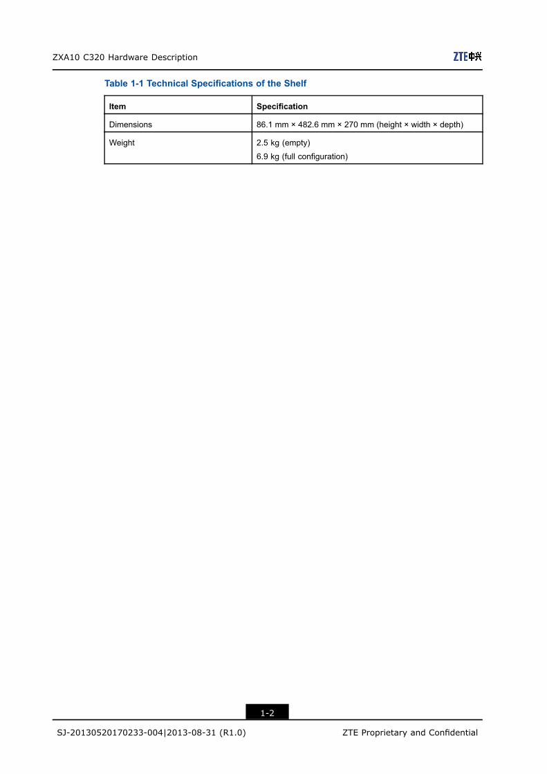
Technical SpecificationsTable 1-1 lists the technical specifications of the shelf.
1-1
SJ-20130520170233-004|2013-08-31 (R1.0) ZTE Proprietary and Confidential
ZXA10 C320 Hardware Description
Table 1-1 Technical Specifications of the Shelf
Item Specification
Dimensions 86.1 mm × 482.6 mm × 270 mm (height × width × depth)
Weight 2.5 kg (empty)
6.9 kg (full configuration)
1-2
SJ-20130520170233-004|2013-08-31 (R1.0) ZTE Proprietary and Confidential

Chapter 2CardsThe ZXA10 C320 is composed of cards and a fan unit, see Table 2-1.
Table 2-1 Card List
Name Description Function Interface
SMXA Switching and control
card
Controls the system and
switches services.
Provides power supply to the
system.
One out-of-band Network
Management (NM) interface
One debugging serial port
One 10GE optical interface
(can be configured as one GE
optical interface)
One GE optical interface
One GE electrical interface
One environment monitoring
interface
One -48 V DC power interface
GTGH 16-port GPON
interface card
Provides GPON access. 16 GPON interfaces
GTGO 8-port GPON interface
card
Provides GPON access. 8 GPON interfaces
FTGK 48-port P2P interface
card
Provides P2P access. 48 GE/FE interfaces
PRAM AC power card Provides power supply to the
system.
One AC power input interface
One DC power output interface
One battery interface
One temperature sensor
interface
MWMT Backplane Provides the electrical
interconnection of each card
in the system.
-
FAN-
C320
Fan unit Provides ventilation for the
system.
-
Table of Contents
SMXA Card ................................................................................................................2-2GPON Interface Cards ...............................................................................................2-5
2-1
SJ-20130520170233-004|2013-08-31 (R1.0) ZTE Proprietary and Confidential

ZXA10 C320 Hardware Description
P2P Interface Card.....................................................................................................2-8Power Card ..............................................................................................................2-10Backplane ................................................................................................................2-12Fan Unit ...................................................................................................................2-13
2.1 SMXA CardOverviewThe switching and control card SMXA is the service switching, management, and controlcenter of the ZXA10 C320.
PanelFigure 2-1 shows the panel of the SMXA card.
Figure 2-1 The SMXA Panel
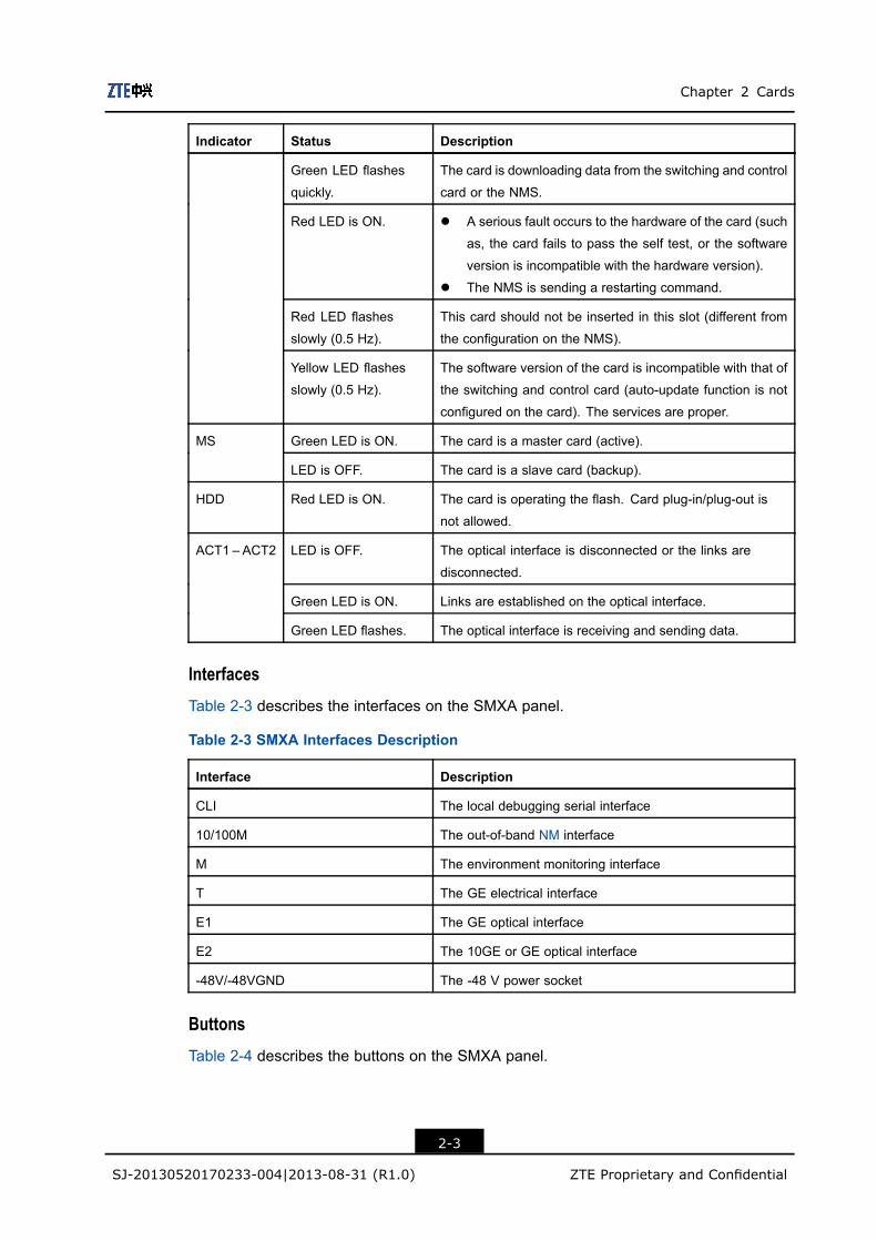
IndicatorsTable 2-2 describes the indicators on the SMXA card.
Table 2-2 SMXA Indicators Description
Indicator Status Description
LED is OFF. The power of the equipment is not supplied from the panel,
but can be supplied from the backplane.
Green LED is ON. The power supply from the panel is proper.
PWR
Red LED is ON. The power supply from the panel is proper.
LED is OFF. The card is not powered on, or the Central Processing Unit
(CPU) is not started.
Green LED flashes
slowly (0.5 Hz).
The card runs properly.
Green LED is ON. l The card passes the self test, but fails to obtain data
from the switching and control card or NMS.
l The card is running the booting program, or is down-
loading a software version from the switching and con-
trol card.
l The card cannot operate because there is no legal soft-
ware version.
RUN
2-2
SJ-20130520170233-004|2013-08-31 (R1.0) ZTE Proprietary and Confidential
Chapter 2 Cards
Indicator Status Description
Green LED flashes
quickly.
The card is downloading data from the switching and control
card or the NMS.
Red LED is ON. l A serious fault occurs to the hardware of the card (such
as, the card fails to pass the self test, or the software
version is incompatible with the hardware version).
l The NMS is sending a restarting command.
Red LED flashes
slowly (0.5 Hz).
This card should not be inserted in this slot (different from
the configuration on the NMS).
Yellow LED flashes
slowly (0.5 Hz).
The software version of the card is incompatible with that of
the switching and control card (auto-update function is not
configured on the card). The services are proper.
Green LED is ON. The card is a master card (active).MS
LED is OFF. The card is a slave card (backup).
HDD Red LED is ON. The card is operating the flash. Card plug-in/plug-out is
not allowed.
LED is OFF. The optical interface is disconnected or the links are
disconnected.
Green LED is ON. Links are established on the optical interface.
ACT1 – ACT2
Green LED flashes. The optical interface is receiving and sending data.
InterfacesTable 2-3 describes the interfaces on the SMXA panel.
Table 2-3 SMXA Interfaces Description
Interface Description
CLI The local debugging serial interface
10/100M The out-of-band NM interface
M The environment monitoring interface
T The GE electrical interface
E1 The GE optical interface
E2 The 10GE or GE optical interface
-48V/-48VGND The -48 V power socket
ButtonsTable 2-4 describes the buttons on the SMXA panel.
2-3
SJ-20130520170233-004|2013-08-31 (R1.0) ZTE Proprietary and Confidential

ZXA10 C320 Hardware Description
Table 2-4 SMXA Buttons Description
Button Description
ON/OFF To enable/disable the power supply of the equipment
RST To reset the card
Principle DiagramFigure 2-2 shows the principle diagram of the SMXA card.
Figure 2-2 SMXA Principle Diagram
Table 2-5 describes the module functions of switching and control cards.
Table 2-5 Switching and Control Card Module Functions
Module Function
Switching module The switching center of data service, implements data switching,
Ethernet, VLAN, multicast, IP route, QoS, and security functions.
Management and control
module
Consists of control software, protocol processing software, overhead
processing, Ethernet switching chip, and control CPU, provides
interfaces for cards to forcedly download versions and reset
hardware/software , provides online detection for cards, implements
fan detection and control functions.
Clock module Processes system clock and time, complies with ITU-T G.8262,
G.8264, and G.781.
Power module Provides input interface for DC power, provides power protection,
monitoring, filtering functions, including lightning-proof, power filtering,
and prevention of overload/underload .
2-4
SJ-20130520170233-004|2013-08-31 (R1.0) ZTE Proprietary and Confidential

Chapter 2 Cards
Technical SpecificationsTable 2-6 lists the technical specifications of the SMXA card.
Table 2-6 Technical Specification of SMXA
Item Specification
Power consumption 27.5 W
Dimensions 200.25 mm × 37 mm × 225 mm (height × width × depth)
Weight 1.14 kg
2.2 GPON Interface CardsOverviewTheGPON interface cards provideGPON access. The ZXA10C320 supports the followingGPON interface cards:
l GTGH: 16-port GPON interface cardl GTGO: 8-port GPON interface card
PanelFigure 2-3Figure 2-4, and Figure 2-4 show the GPON interface card panels.
Figure 2-3 GTGH Panel
Figure 2-4 GTGO Panel
IndicatorsTable 2-7 describes the indicators of the GPON interface cards.
2-5
SJ-20130520170233-004|2013-08-31 (R1.0) ZTE Proprietary and Confidential

ZXA10 C320 Hardware Description
Table 2-7 GPON Interface Cards Indicator Description
Indicator Status Description
LED is OFF. l The card is powered off.
l The card does not match.
l CPU is not started.
Green LED is ON. The card self-checking completes but fails to receive
data from the switching and control card or NM.
Green LED flashes quickly. The card is downloading data from the network
management server.
Green LED flashes slowly
(0.5 Hz).
The card runs properly.
Red LED is ON. The card hardware is faulty.
Red LED flashes slowly (0.5
Hz).
The card is installed in the wrong slot.
RUN
Yellow LED flashes slowly
(0.5 Hz).
The software version of the card does not match that
of the switching and control card. Auto-update is not
configured on the card.
LED is OFF. l No ONU is configured on the GPON interface.
l The GPON interface has no optical module
installed.
l The GPON interface is shutdown.
l The GPON interface is TypeB protection port.
Green LED flashes. The GPON interface and connected ONUs work
properly.
ACTi (i =
1–16)
Red LED is ON. The GPON interface has LOS alarms.
InterfacesGPON interface cards provide 16/8 GPON interfaces.
ButtonThe RST button is used for resetting card.
Principle DiagramFigure 2-5 shows the principle diagram of the GPON interface cards.
2-6
SJ-20130520170233-004|2013-08-31 (R1.0) ZTE Proprietary and Confidential

Chapter 2 Cards
Figure 2-5 GPON Interface Cards Principle Diagram
Table 2-8 describes the module functions of GPON interface cards.
Table 2-8 GPON Interface Cards Module Functions
Module Function
Management and control
module
Manages and controls the card, implement card configuration.
PON MAC module Implement the PON functions defined by ITU-T G.984.3.
TM module Processes data in service layer, including bandwidth management and
QoS process, satisfies the SLA requirement. The process function
is compatible with TR156.
PON optical module Provides PON-C optical interface, complies with ITU-T G.984.2.
Clock module Process system clock, complies with ITU-T G.8262, G.8264, and
G.781.
Technical SpecificationsTable 2-9 lists technical specifications of the GPON interface cards.
Table 2-9 GPON Interface Cards Technical Specifications
Item Specification
Power consumption GTGH: 55 W
GTGO: 30 W
Dimensions 395.5 mm × 22.5 mm × 225 mm (Height × Width × Depth)
Weight GTGH: 1.000 kg
GTGO: 0.925 kg
2-7
SJ-20130520170233-004|2013-08-31 (R1.0) ZTE Proprietary and Confidential

ZXA10 C320 Hardware Description
2.3 P2P Interface CardOverviewThe FTGK card is a 48-port P2P interface card. It uses WDM technology and single opticalfiber for transmitting and receiving.
PanelFigure 2-6 shows the FTGK panel.
Figure 2-6 FTGK Panel
IndicatorTable 2-10 describes the indicators of the FTGK card.
Table 2-10 FTGK Indicator Description
Indicator Status Description
LED is OFF. The card is powered off, or CPU is not started.
Green LED is ON. l The card passes the self test, but fails to obtain data
from the switching and control card or NMS.
l The card is running the booting program, or is
downloading a software version from the switching
and control card.
l The card cannot operate because there is no legal
software version.
Green LED flashes
quickly.
The card is downloading data from the switching and
control card or the NMS.
Green LED flashes
slowly (0.5 Hz).
The card runs properly.
Red LED is ON. l A serious fault occurs to the hardware of the card (such
as, the card fails to pass the self test, or the software
version is incompatible with the hardware version).
l The NMS is sending a restarting command.
Red LED flashes
slowly (0.5 Hz).
This card should not be inserted in this slot (different from
the configuration of the NMS).
RUN
Yellow LED flashes
slowly (0.5 Hz).
The software version of the card is incompatible with that
of the switching and control card (auto-update function is
not configured on the card). The services are proper.
2-8
SJ-20130520170233-004|2013-08-31 (R1.0) ZTE Proprietary and Confidential

Chapter 2 Cards
Indicator Status Description
LED is OFF. No. i GE/FE optical port is not connected.
Green LED is ON. No. i GE/FE optical port is connected (LINK).
LEDi (i = 1 –
48)
Green LED flashes. No. i GE/FE optical port is sending and receiving the data
(ACTIVE).
InterfaceThe FTGK card provides 48 FE/GE optical interfaces (24 ports, each port provides 2interfaces).
Principle DiagramFigure 2-7 shows the principle diagram of the FTGK card.
Figure 2-7 FTGK Principle Diagram
Table 2-11 describes the module functions of the FTGK card.
Table 2-11 FTGK Module Function
Module Function
Management and control
module
Implements card configuration, traffic management and optical module
management, and status detection of optical module.
Switching module Implements conversion of optical module and backplane bus,
implements VLAN and Ethernet functions.
Clock module Supports all optical interface to use system clock for clock
synchronization. When the card is used for uplink, the synchronized
clock from the optical port is sent to the switching and control card
works as the system clock.
P2P optical module Provides GE/FE optical interface.
2-9
SJ-20130520170233-004|2013-08-31 (R1.0) ZTE Proprietary and Confidential

ZXA10 C320 Hardware Description
Technical SpecificationTable 2-12 lists technical specifications of the FTGK card.
Table 2-12 FTGK Technical Specification
Item Specification
Power consumption 85 W
Dimensions 395.5 mm × 22.5 mm × 225 mm (Height × Width × Depth)
Weight 1.51 kg
2.4 Power CardOverviewThe power card PRAM card uses 110 V or 220 V AC power and provides power supply toeach card.
PanelFigure 2-8 shows the PRAM card panel.
Figure 2-8 PRAM Panel
IndicatorsTable 2-13 describes the indicators of the PRAM card.
Table 2-13 PRAM Indicator Description
Indicator Status Description
Green LED is on. Power is on.PWR
Green LED is off Power is abnormal.
Green LED is on. The battery works properly.
Green LED flashes
quickly.
The battery is discharging, or the battery is
reversely connected.
BATTERY
Green LED is off. The battery is not available.
InterfacesTable 2-14 describes the interfaces of the PRAM card.
2-10
SJ-20130520170233-004|2013-08-31 (R1.0) ZTE Proprietary and Confidential

Chapter 2 Cards
Table 2-14 PRAM Interface Description
Interface Description
AC power interface
(100-240V AC 50/60HZ)
Connects to 110 V/220 V AC power.
DC power interface (48V
1.2A)
Provides -48 V DC output.
48V+ connects to -48 V. 48- connects to -48 V RTN (-48 V ground).
Battery interface Connects to a storage battery.
BAT- connects to the negative of the battery. BAT+ connects to the
positive of the battery.
TEMP SENSOR Connects to a temperature sensor, for battery temperature
compensation.
Without a temperature sensor, the default temperature is set to 25 ℃and the floating charge voltage is 53.5 V.
ButtonTable 2-15 describes the button on the PRAM panel.
Table 2-15 PRAM Button Description
Button Description
ON/OFF To enable/disable the power supply of the equipment
Principle DiagramFigure 2-9 shows the principle diagram of the PRAM card.
Figure 2-9 PRAM Principle Diagram
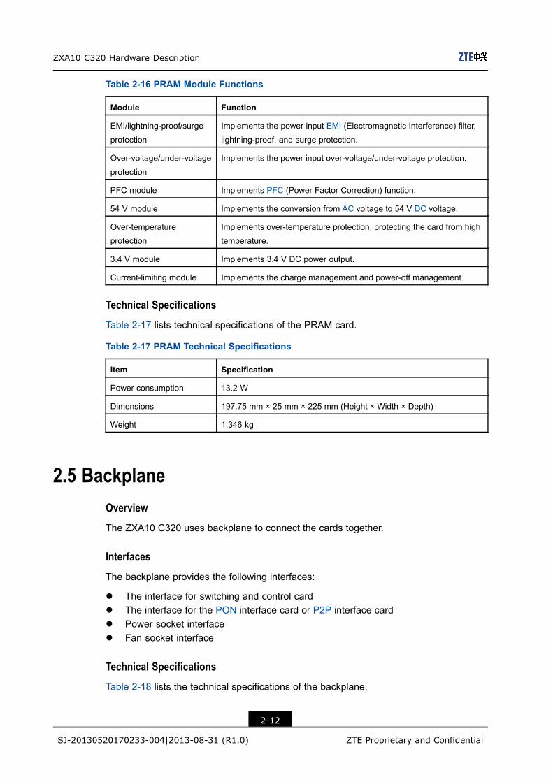
Table 2-16 describes functions of each module of the PRAM card.
2-11
SJ-20130520170233-004|2013-08-31 (R1.0) ZTE Proprietary and Confidential
ZXA10 C320 Hardware Description
Table 2-16 PRAM Module Functions
Module Function
EMI/lightning-proof/surge
protection
Implements the power input EMI (Electromagnetic Interference) filter,
lightning-proof, and surge protection.
Over-voltage/under-voltage
protection
Implements the power input over-voltage/under-voltage protection.
PFC module Implements PFC (Power Factor Correction) function.
54 V module Implements the conversion from AC voltage to 54 V DC voltage.
Over-temperature
protection
Implements over-temperature protection, protecting the card from high
temperature.
3.4 V module Implements 3.4 V DC power output.
Current-limiting module Implements the charge management and power-off management.
Technical SpecificationsTable 2-17 lists technical specifications of the PRAM card.
Table 2-17 PRAM Technical Specifications
Item Specification
Power consumption 13.2 W
Dimensions 197.75 mm × 25 mm × 225 mm (Height × Width × Depth)
Weight 1.346 kg
2.5 BackplaneOverviewThe ZXA10 C320 uses backplane to connect the cards together.
InterfacesThe backplane provides the following interfaces:
l The interface for switching and control cardl The interface for the PON interface card or P2P interface cardl Power socket interfacel Fan socket interface
Technical SpecificationsTable 2-18 lists the technical specifications of the backplane.
2-12
SJ-20130520170233-004|2013-08-31 (R1.0) ZTE Proprietary and Confidential

Chapter 2 Cards
Table 2-18 Backplane Technical Specifications
Item Specification
Power consumption -
Dimensions 81 mm × 411 mm × 4.7 mm (height × width × depth)
Weight 0.395 kg
2.6 Fan UnitFunctional ModulesThe fan unit consists of the following functional modules:
l Power filtering and protection modules, including the lightning protection module,anti-reverse-connection protection module, over-voltage protection module, and thedelayed-start module.
l The fan control modulel The fan status detection module
IndicatorsTable 2-19 describes the indicators of the fan unit.
Table 2-19 Description on the Indicators of the Fan Unit
Indicator Status Description
RUN Green LED is ON. The fan runs properly.
ALM Red LED flashes. The fan is faulty.
Technical SpecificationsTable 2-20 lists the technical specifications of the fan unit.
Table 2-20 Technical Specifications of the Fan Unit
Item Specification
Power consumption 20 W
Dimensions 84.3 mm × 35.8 mm × 247.9 mm( height × width × depth)
Weight 0.425 kg
2-13
SJ-20130520170233-004|2013-08-31 (R1.0) ZTE Proprietary and Confidential

ZXA10 C320 Hardware Description
This page intentionally left blank.
2-14
SJ-20130520170233-004|2013-08-31 (R1.0) ZTE Proprietary and Confidential

Chapter 3CablesTable 3-1 lists the cables used by the ZXA10 C320.
Table 3-1 ZXA10 C320 Cables
Cable Description
Power cable Connects -48 V DC power to the ZXA10 C320.
Network cable Connects to an Ethernet electrical interface.
Serial port cable Connects the serial port of a maintenance computer to the CLI interfaceon the ZXA10 C320.
Fiber pigtail Connects optical fibers to an Ethernet optical interface or PON interface.
Table of Contents
Power Cable ..............................................................................................................3-1Network Cable............................................................................................................3-2Serial Port Cable ........................................................................................................3-3Fiber Pigtail ................................................................................................................3-4
3.1 Power CableCable StructureFigure 3-1 shows the structure of 3-core power cable.
Figure 3-1 Power Cable Structure
Cable ConnectionEnd A of the power cable is connected to the ZXA10 C320 shelf, supplying the power to theshelf. End B of the power cable is connected to the DC terminal of the power distributor.
3-1
SJ-20130520170233-004|2013-08-31 (R1.0) ZTE Proprietary and Confidential

ZXA10 C320 Hardware Description
3.2 Network CableCable StructureNetwork cables are cat-5 cables with two ends of RJ45 connectors, see Figure 3-2.
Figure 3-2 Network Cable Structure
Pin ConnectionsTable 3-2 lists the pin connections of a network cable.
Table 3-2 Pin Connections of a Network cable
End A End B Signal
RJ45_3 (Crossover)RJ45_1
RJ45_1 (Straight-through)
TPOP
RJ45_6 (Crossover)RJ45_2
RJ45_2 (Straight-through)
TPOP
RJ45_1 (Crossover)RJ45_3
RJ45_3 (Straight-through)
TPIP
RJ45_2 (Crossover)RJ45_6
RJ45_6 (Straight-through)
TPIN
3-2
SJ-20130520170233-004|2013-08-31 (R1.0) ZTE Proprietary and Confidential

Chapter 3 Cables
Note:
The network cable cannot be longer than 100 m.
3.3 Serial Port CableCable StructureFigure 3-3 shows the serial port cable structure. End A is a RJ45 connector and End B isa DB9 connector.
Figure 3-3 Serial Port Cable Structure
Pin ConnectionsTable 3-3 lists pin connections of the serial port cable.
Table 3-3 Pin Connections of the Serial Port Cable
End A End B
3 3
4 5
5 5
6 2
Note: Other pins are null.
3-3
SJ-20130520170233-004|2013-08-31 (R1.0) ZTE Proprietary and Confidential

ZXA10 C320 Hardware Description
3.4 Fiber PigtailCable DescriptionA fiber pigtail is a single short fiber which connects the optical interface or the opticaladapter on the ODF. A fiber pigtail has optical connectors at both ends.
Connector DescriptionTable 3-4 describes the optical connectors.
Table 3-4 Optical Connector
Type Description Image Interface
LC/PC Lucent connector (for physical contact),
with regular polish quality
Ethernet optical
interface
SC/PC Square optical connector (for physical
contact), with regular polish quality
PON optical
interface
3-4
SJ-20130520170233-004|2013-08-31 (R1.0) ZTE Proprietary and Confidential

GlossaryAC- Alternating Current
CPU- Central Processing Unit
DC- Direct Current
EMI- Electromagnetic Interference
FE- Fast Ethernet
GE- Gigabit Ethernet
GPON- Gigabit Passive Optical Network
IP- Internet Protocol
LOS- Loss Of Signal
MAC- Media Access Control
NM- Network Management
ODF- Optical Distribution Frame
P2P- Point to Point
PFC- Power Factor Correction
PON- Passive Optical Network
QoS- Quality of Service
SLA- Service Level Agreement
I
SJ-20130520170233-004|2013-08-31 (R1.0) ZTE Proprietary and Confidential

ZXA10 C320 Hardware Description
TM- TrafficManagement
VLAN- Virtual Local Area Network
WDM- Wavelength Division Multiplexing
II
SJ-20130520170233-004|2013-08-31 (R1.0) ZTE Proprietary and Confidential