
Optical Terminology - Linköping University · In photography, the most utilised wavelengths are in...
25
192 Optical Terminology
Transcript of Optical Terminology - Linköping University · In photography, the most utilised wavelengths are in...

192
Optical Terminology
193
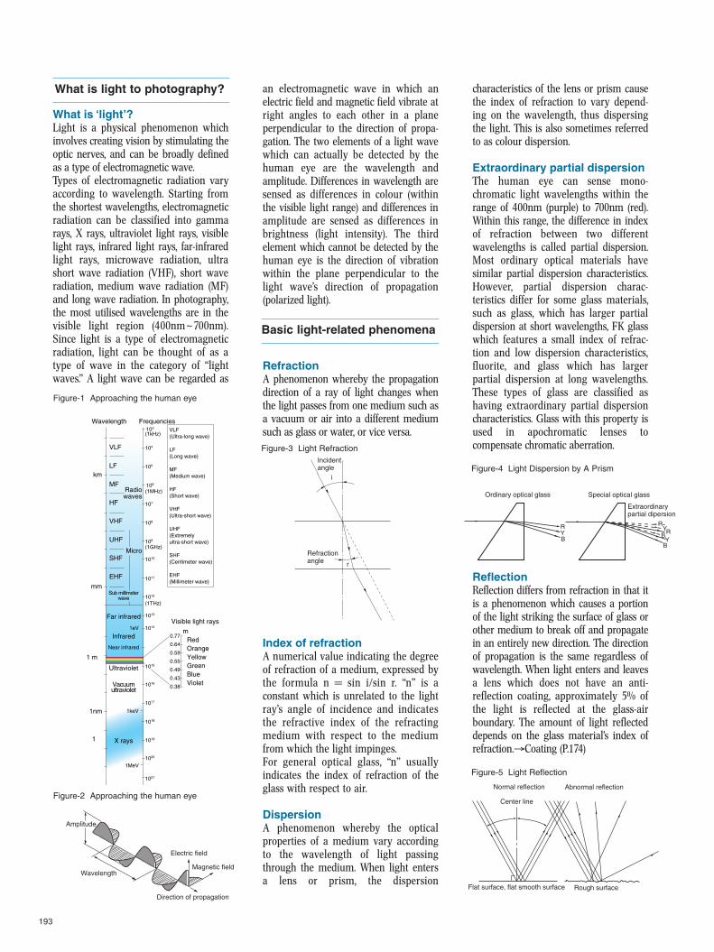
What is ‘light’?Light is a physical phenomenon whichinvolves creating vision by stimulating theoptic nerves, and can be broadly definedas a type of electromagnetic wave.Types of electromagnetic radiation varyaccording to wavelength. Starting fromthe shortest wavelengths, electromagneticradiation can be classified into gammarays, X rays, ultraviolet light rays, visiblelight rays, infrared light rays, far-infraredlight rays, microwave radiation, ultrashort wave radiation (VHF), short waveradiation, medium wave radiation (MF)and long wave radiation. In photography,the most utilised wavelengths are in thevisible light region (400nm~700nm).Since light is a type of electromagneticradiation, light can be thought of as atype of wave in the category of “lightwaves.” A light wave can be regarded as
an electromagnetic wave in which anelectric field and magnetic field vibrate atright angles to each other in a planeperpendicular to the direction of propa-gation. The two elements of a light wavewhich can actually be detected by thehuman eye are the wavelength andamplitude. Differences in wavelength aresensed as differences in colour (withinthe visible light range) and differences inamplitude are sensed as differences inbrightness (light intensity). The thirdelement which cannot be detected by thehuman eye is the direction of vibrationwithin the plane perpendicular to thelight wave’s direction of propagation(polarized light).
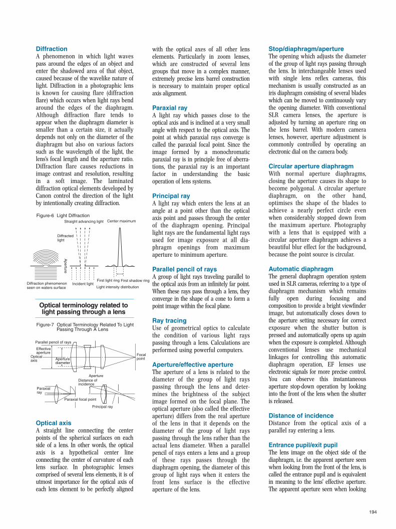
RefractionA phenomenon whereby the propagationdirection of a ray of light changes whenthe light passes from one medium such asa vacuum or air into a different mediumsuch as glass or water, or vice versa.
Index of refractionA numerical value indicating the degreeof refraction of a medium, expressed bythe formula n = sin i/sin r. “n” is aconstant which is unrelated to the lightray’s angle of incidence and indicatesthe refractive index of the refractingmedium with respect to the mediumfrom which the light impinges.For general optical glass, “n” usuallyindicates the index of refraction of theglass with respect to air.
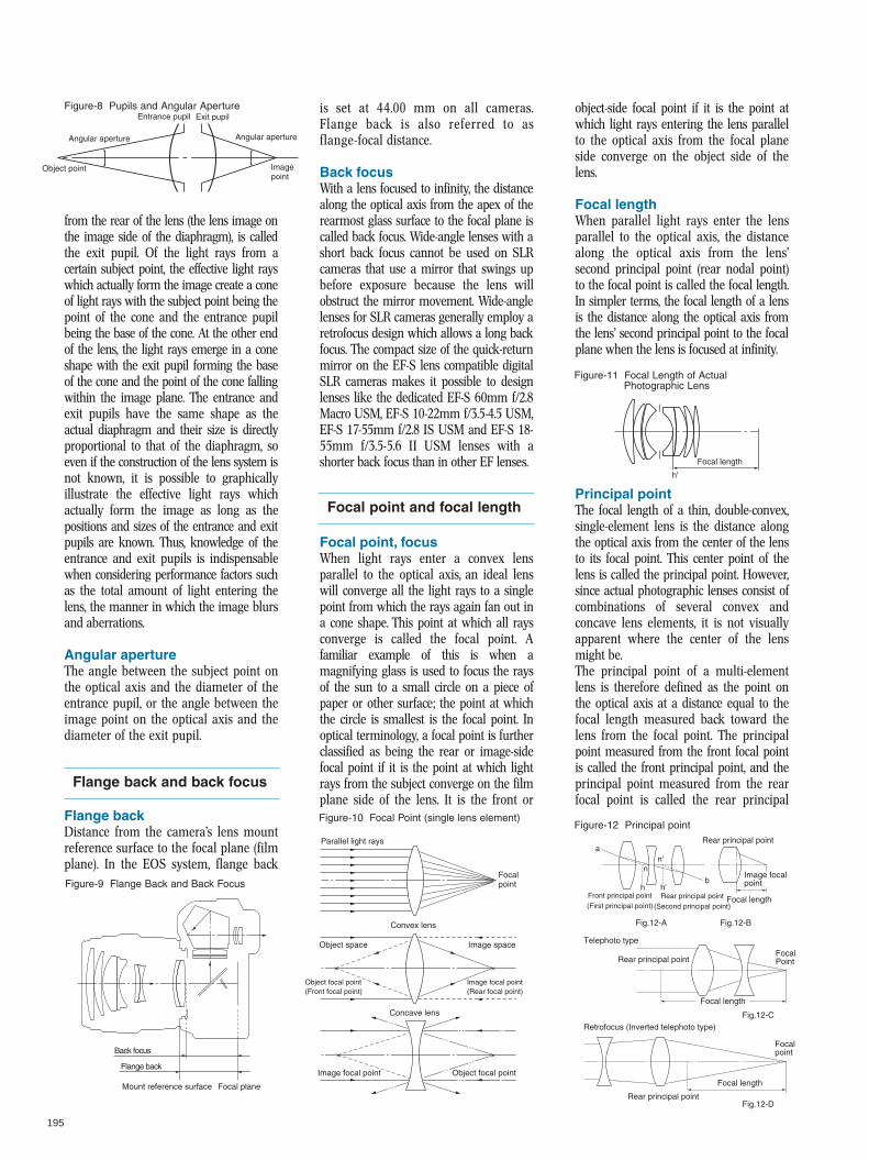
DispersionA phenomenon whereby the opticalproperties of a medium vary accordingto the wavelength of light passingthrough the medium. When light entersa lens or prism, the dispersion
characteristics of the lens or prism causethe index of refraction to vary depend-ing on the wavelength, thus dispersingthe light. This is also sometimes referredto as colour dispersion.
Extraordinary partial dispersionThe human eye can sense mono-chromatic light wavelengths within therange of 400nm (purple) to 700nm (red).Within this range, the difference in indexof refraction between two differentwavelengths is called partial dispersion.Most ordinary optical materials havesimilar partial dispersion characteristics.However, partial dispersion charac-teristics differ for some glass materials,such as glass, which has larger partialdispersion at short wavelengths, FK glasswhich features a small index of refrac-tion and low dispersion characteristics,fluorite, and glass which has largerpartial dispersion at long wavelengths.These types of glass are classified ashaving extraordinary partial dispersioncharacteristics. Glass with this property isused in apochromatic lenses tocompensate chromatic aberration.
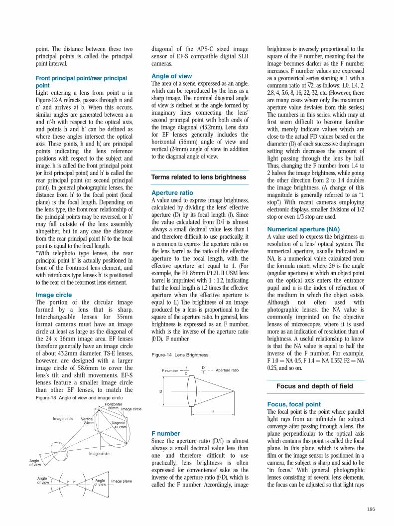
ReflectionReflection differs from refraction in that itis a phenomenon which causes a portionof the light striking the surface of glass orother medium to break off and propagatein an entirely new direction. The directionof propagation is the same regardless ofwavelength. When light enters and leavesa lens which does not have an anti-reflection coating, approximately 5% ofthe light is reflected at the glass-airboundary. The amount of light reflecteddepends on the glass material’s index ofrefraction.→Coating (P.174)
What is light to photography?
Basic light-related phenomena
Figure-1 Approaching the human eye
Figure-2 Approaching the human eye
Figure-3 Light Refraction
Figure-4 Light Dispersion by A Prism
Figure-5 Light Reflection
Wavelength
VLF
(1kHz)
(1MHz)
(1GHz)
(1THz)
LF
MFRadiowaves
km
mm
0.77RedOrangeYellowGreenBlueViolet
0.64
0.59
0.55
0.49
0.43
0.38
1nm
1 m
1
HF
VHF
UHF
SHF
EHF
VLF(Ultra-long wave)
LF(Long wave)
MF(Medium wave)
HF(Short wave)
VHF(Ultra-short wave)
UHF(Extremelyultra-short wave)
SHF(Centimeter wave)
EHF(Millimeter wave)
Infrared
Ultraviolet
X rays
γ rays
1eV
1keV
1MeV
1GeV
Micro
Frequencies103
104
105
106
107
108
109
1010
1011
1012
1013
1014
1016
1017
1018
1019
1020
1021
1022
1023
Sub millimeterwave
Far infrared
Near infrared
Vacuumultraviolet
Visible light rays
µm
1015
Amplitude
Wavelength
Direction of propagation
Electric field
Magnetic field
Incident angle
Refraction angle
i
r
Ordinary optical glass
RRYB
RY
YB
B
Special optical glass
Extraordinary partial dipersion
Normal reflection Abnormal reflection
Flat surface, flat smooth surface Rough surface
Center line
194
DiffractionA phenomenon in which light wavespass around the edges of an object andenter the shadowed area of that object,caused because of the wavelike nature oflight. Diffraction in a photographic lensis known for causing flare (diffractionflare) which occurs when light rays bendaround the edges of the diaphragm.Although diffraction flare tends toappear when the diaphragm diameter issmaller than a certain size, it actuallydepends not only on the diameter of thediaphragm but also on various factorssuch as the wavelength of the light, thelens’s focal length and the aperture ratio.Diffraction flare causes reductions inimage contrast and resolution, resultingin a soft image. The laminateddiffraction optical elements developed byCanon control the direction of the lightby intentionally creating diffraction.
Optical axisA straight line connecting the centerpoints of the spherical surfaces on eachside of a lens. In other words, the opticalaxis is a hypothetical center lineconnecting the center of curvature of eachlens surface. In photographic lensescomprised of several lens elements, it is ofutmost importance for the optical axis ofeach lens element to be perfectly aligned
with the optical axes of all other lenselements. Particularly in zoom lenses,which are constructed of several lensgroups that move in a complex manner,extremely precise lens barrel constructionis necessary to maintain proper opticalaxis alignment.
Paraxial rayA light ray which passes close to theoptical axis and is inclined at a very smallangle with respect to the optical axis. Thepoint at which paraxial rays converge iscalled the paraxial focal point. Since theimage formed by a monochromaticparaxial ray is in principle free of aberra-tions, the paraxial ray is an importantfactor in understanding the basicoperation of lens systems.
Principal rayA light ray which enters the lens at anangle at a point other than the opticalaxis point and passes through the centerof the diaphragm opening. Principallight rays are the fundamental light raysused for image exposure at all dia-phragm openings from maximumaperture to minimum aperture.
Parallel pencil of raysA group of light rays traveling parallel tothe optical axis from an infinitely far point.When these rays pass through a lens, theyconverge in the shape of a cone to form apoint image within the focal plane.
Ray tracingUse of geometrical optics to calculatethe condition of various light rayspassing through a lens. Calculations areperformed using powerful computers.
Aperture/effective apertureThe aperture of a lens is related to thediameter of the group of light rayspassing through the lens and deter-mines the brightness of the subjectimage formed on the focal plane. Theoptical aperture (also called the effectiveaperture) differs from the real apertureof the lens in that it depends on thediameter of the group of light rayspassing through the lens rather than theactual lens diameter. When a parallelpencil of rays enters a lens and a groupof these rays passes through thediaphragm opening, the diameter of thisgroup of light rays when it enters thefront lens surface is the effectiveaperture of the lens.
Stop/diaphragm/apertureThe opening which adjusts the diameterof the group of light rays passing throughthe lens. In interchangeable lenses usedwith single lens reflex cameras, thismechanism is usually constructed as aniris diaphragm consisting of several bladeswhich can be moved to continuously varythe opening diameter. With conventionalSLR camera lenses, the aperture isadjusted by turning an aperture ring onthe lens barrel. With modern cameralenses, however, aperture adjustment iscommonly controlled by operating anelectronic dial on the camera body.
Circular aperture diaphragmWith normal aperture diaphragms,closing the aperture causes its shape tobecome polygonal. A circular aperturediaphragm, on the other hand,optimises the shape of the blades toachieve a nearly perfect circle evenwhen considerably stopped down fromthe maximum aperture. Photographywith a lens that is equipped with acircular aperture diaphragm achieves abeautiful blur effect for the background,because the point source is circular.
Automatic diaphragmThe general diaphragm operation systemused in SLR cameras, referring to a type ofdiaphragm mechanism which remainsfully open during focusing andcomposition to provide a bright viewfinderimage, but automatically closes down tothe aperture setting necessary for correctexposure when the shutter button ispressed and automatically opens up againwhen the exposure is completed. Althoughconventional lenses use mechanicallinkages for controlling this automaticdiaphragm operation, EF lenses useelectronic signals for more precise control.You can observe this instantaneousaperture stop-down operation by lookinginto the front of the lens when the shutteris released.
Distance of incidenceDistance from the optical axis of aparallel ray entering a lens.
Entrance pupil/exit pupilThe lens image on the object side of thediaphragm, i.e. the apparent aperture seenwhen looking from the front of the lens, iscalled the entrance pupil and is equivalentin meaning to the lens’ effective aperture.The apparent aperture seen when looking
Optical terminology related tolight passing through a lens
Figure-7 Optical Terminology Related To LightPassing Through A Lens
Figure-6 Light Diffraction
Parallel pencil of rays
Paraxial ray
Paraxial focal point
Distance of incidence
Principal ray
Aperture
Focal pointAperture
diameter
Optical axis
Effective aperture
Diffracted light
Straight advancing light Center maximum
Aperture
Diffraction phenomenon seen on waters surface
Incident lightLight intensity distribution
First light ring First shadow ring
195
from the rear of the lens (the lens image onthe image side of the diaphragm), is calledthe exit pupil. Of the light rays from acertain subject point, the effective light rayswhich actually form the image create a coneof light rays with the subject point being thepoint of the cone and the entrance pupilbeing the base of the cone. At the other endof the lens, the light rays emerge in a coneshape with the exit pupil forming the baseof the cone and the point of the cone fallingwithin the image plane. The entrance andexit pupils have the same shape as theactual diaphragm and their size is directlyproportional to that of the diaphragm, soeven if the construction of the lens system isnot known, it is possible to graphicallyillustrate the effective light rays whichactually form the image as long as thepositions and sizes of the entrance and exitpupils are known. Thus, knowledge of theentrance and exit pupils is indispensablewhen considering performance factors suchas the total amount of light entering thelens, the manner in which the image blursand aberrations.
Angular apertureThe angle between the subject point onthe optical axis and the diameter of theentrance pupil, or the angle between theimage point on the optical axis and thediameter of the exit pupil.
Flange backDistance from the camera’s lens mountreference surface to the focal plane (filmplane). In the EOS system, flange back
is set at 44.00 mm on all cameras.Flange back is also referred to asflange-focal distance.
Back focusWith a lens focused to infinity, the distancealong the optical axis from the apex of therearmost glass surface to the focal plane iscalled back focus. Wide-angle lenses with ashort back focus cannot be used on SLRcameras that use a mirror that swings upbefore exposure because the lens willobstruct the mirror movement. Wide-anglelenses for SLR cameras generally employ aretrofocus design which allows a long backfocus. The compact size of the quick-returnmirror on the EF-S lens compatible digitalSLR cameras makes it possible to designlenses like the dedicated EF-S 60mm f/2.8Macro USM, EF-S 10-22mm f/3.5-4.5 USM,EF-S 17-55mm f/2.8 IS USM and EF-S 18-55mm f/3.5-5.6 II USM lenses with ashorter back focus than in other EF lenses.
Focal point, focusWhen light rays enter a convex lensparallel to the optical axis, an ideal lenswill converge all the light rays to a singlepoint from which the rays again fan out ina cone shape. This point at which all raysconverge is called the focal point. Afamiliar example of this is when amagnifying glass is used to focus the raysof the sun to a small circle on a piece ofpaper or other surface; the point at whichthe circle is smallest is the focal point. Inoptical terminology, a focal point is furtherclassified as being the rear or image-sidefocal point if it is the point at which lightrays from the subject converge on the filmplane side of the lens. It is the front or
object-side focal point if it is the point atwhich light rays entering the lens parallelto the optical axis from the focal planeside converge on the object side of thelens.
Focal lengthWhen parallel light rays enter the lensparallel to the optical axis, the distancealong the optical axis from the lens’second principal point (rear nodal point)to the focal point is called the focal length.In simpler terms, the focal length of a lensis the distance along the optical axis fromthe lens’ second principal point to the focalplane when the lens is focused at infinity.
Principal pointThe focal length of a thin, double-convex,single-element lens is the distance alongthe optical axis from the center of the lensto its focal point. This center point of thelens is called the principal point. However,since actual photographic lenses consist ofcombinations of several convex andconcave lens elements, it is not visuallyapparent where the center of the lensmight be.The principal point of a multi-elementlens is therefore defined as the point onthe optical axis at a distance equal to thefocal length measured back toward thelens from the focal point. The principalpoint measured from the front focal pointis called the front principal point, and theprincipal point measured from the rearfocal point is called the rear principal
Figure-8 Pupils and Angular Aperture
Flange back and back focus
Figure-9 Flange Back and Back Focus
Focal point and focal length
Figure-10 Focal Point (single lens element)
Figure-11 Focal Length of ActualPhotographic Lens
Figure-12 Principal point
Angular aperture
Object point
Entrance pupil Exit pupil
Angular aperture
Image point
Mount reference surface Focal plane
Flange back
Back focus
Parallel light rays
Convex lens
Concave lens
Focal point
Object space Image space
Image focal point (Rear focal point)
Object focal point (Front focal point)
Image focal point Object focal point
Rear principal point
Rear principal point
Rear principal point(Second principal point)
Rear principal point
Front principal point (First principal point)
Focal length
Focal point
Focal Point
Image focal point
Retrofocus (Inverted telephoto type)
a
b
n'n
h h'
Focal length
Focal length
Fig.12-D
Fig.12-C
Fig.12-BFig.12-A
Telephoto type
Focal length
h'
196
point. The distance between these twoprincipal points is called the principalpoint interval.
Front principal point/rear principalpointLight entering a lens from point a inFigure-12-A refracts, passes through n andn’ and arrives at b. When this occurs,similar angles are generated between a-nand n’-b with respect to the optical axis,and points h and h’ can be defined aswhere these angles intersect the opticalaxis. These points, h and h’, are principalpoints indicating the lens referencepositions with respect to the subject andimage. h is called the front principal point(or first principal point) and h’ is called therear principal point (or second principalpoint). In general photographic lenses, thedistance from h’ to the focal point (focalplane) is the focal length. Depending onthe lens type, the front-rear relationship ofthe principal points may be reversed, or h’may fall outside of the lens assemblyaltogether, but in any case the distancefrom the rear principal point h’ to the focalpoint is equal to the focal length.*With telephoto type lenses, the rearprincipal point h’ is actually positioned infront of the frontmost lens element, andwith retrofocus type lenses h’ is positionedto the rear of the rearmost lens element.
Image circleThe portion of the circular imageformed by a lens that is sharp.Interchangeable lenses for 35mmformat cameras must have an imagecircle at least as large as the diagonal ofthe 24 x 36mm image area. EF lensestherefore generally have an image circleof about 43.2mm diameter. TS-E lenses,however, are designed with a largerimage circle of 58.6mm to cover thelens’s tilt and shift movements. EF-Slenses feature a smaller image circlethan other EF lenses, to match the
diagonal of the APS-C sized imagesensor of EF-S compatible digital SLRcameras.
Angle of viewThe area of a scene, expressed as an angle,which can be reproduced by the lens as asharp image. The nominal diagonal angleof view is defined as the angle formed byimaginary lines connecting the lens’second principal point with both ends ofthe image diagonal (43.2mm). Lens datafor EF lenses generally includes thehorizontal (36mm) angle of view andvertical (24mm) angle of view in additionto the diagonal angle of view.
Aperture ratioA value used to express image brightness,calculated by dividing the lens’ effectiveaperture (D) by its focal length (f). Sincethe value calculated from D/f is almostalways a small decimal value less than Iand therefore difficult to use practically, itis common to express the aperture ratio onthe lens barrel as the ratio of the effectiveaperture to the focal length, with theeffective aperture set equal to 1. (Forexample, the EF 85mm f/1.2L II USM lensbarrel is imprinted with 1 : 1.2, indicatingthat the focal length is 1.2 times the effectiveaperture when the effective aperture isequal to 1.) The brightness of an imageproduced by a lens is proportional to thesquare of the aperture ratio. In general, lensbrightness is expressed as an F number,which is the inverse of the aperture ratio(f/D). F number
F numberSince the aperture ratio (D/f) is almostalways a small decimal value less thanone and therefore difficult to usepractically, lens brightness is oftenexpressed for convenience’ sake as theinverse of the aperture ratio (f/D), which iscalled the F number. Accordingly, image
brightness is inversely proportional to thesquare of the F number, meaning that theimage becomes darker as the F numberincreases. F number values are expressedas a geometrical series starting at 1 with acommon ratio of √ 2, as follows: 1.0, 1.4, 2,2.8, 4, 5.6, 8, 16, 22, 32, etc. (However, thereare many cases where only the maximumaperture value deviates from this series.)The numbers in this series, which may atfirst seem difficult to become familiarwith, merely indicate values which areclose to the actual FD values based on thediameter (D) of each successive diaphragmsetting which decreases the amount oflight passing through the lens by half.Thus, changing the F number from 1.4 to2 halves the image brightness, while goingthe other direction from 2 to 1.4 doublesthe image brightness. (A change of thismagnitude is generally referred to as “1stop”.) With recent cameras employingelectronic displays, smaller divisions of 1/2stop or even 1/3 stop are used.
Numerical aperture (NA)A value used to express the brightness orresolution of a lens’ optical system. Thenumerical aperture, usually indicated asNA, is a numerical value calculated fromthe formula nsinθ, where 2θ is the angle(angular aperture) at which an object pointon the optical axis enters the entrancepupil and n is the index of refraction ofthe medium in which the object exists.Although not often used withphotographic lenses, the NA value iscommonly imprinted on the objectivelenses of microscopes, where it is usedmore as an indication of resolution than ofbrightness. A useful relationship to knowis that the NA value is equal to half theinverse of the F number. For example,F 1.0 = NA 0.5, F 1.4 = NA 0.357, F2 = NA0.25, and so on.
Focus, focal pointThe focal point is the point where parallellight rays from an infinitely far subjectconverge after passing through a lens. Theplane perpendicular to the optical axiswhich contains this point is called the focalplane. In this plane, which is where thefilm or the image sensor is positioned in acamera, the subject is sharp and said to be“in focus.” With general photographiclenses consisting of several lens elements,the focus can be adjusted so that light rays
Figure-13 Angle of view and image circle
Figure-14 Lens Brightness
Focus and depth of field
Terms related to lens brightness
Angle of view Angle
of viewImage planeh h'
Diagonal 43.2mm
Image circle
Image circle
Angle of view
Vertical 24mm
Horizontal 36mm
Image circle
fD
Aperture ratioF numberDf
f
D
197
from subjects closer than “infinity”converge at a point in the focal plane.
Circle of confusionSince all lenses contain a certain amountof spherical aberration and astigmatism,they cannot perfectly converge rays from asubject point to form a true image point(i.e., an infinitely small dot with zero area).In other words, images are formed from acomposite of dots (not points) having acertain area, or size. Since the imagebecomes less sharp as the size of thesedots increases, the dots are called “circlesof confusion.” Thus, one way of indicatingthe quality of a lens is by the smallest dotit can form, or its “minimum circle ofconfusion.” The maximum allowable dotsize in an image is called the “permissiblecircle of confusion.”
Permissible circle of confusionThe largest circle of confusion which stillappears as a “point” in the image. Imagesharpness as sensed by the human eye isclosely related to the sharpness of theactual image and the “resolution” ofhuman eyesight. In photography, imagesharpness is also dependent on the degreeof image enlargement or projectiondistance and the distance from which theimage is viewed. In other words, inpractical work it is possible to determinecertain “allowances” for producing imageswhich, although actually blurred to acertain degree, still appear sharp to theobserver. For 35mm single lens reflexcameras, the permissible circle of confusionis about 1/1000~1/1500 the length of thefilm diagonal, assuming the image isenlarged to a 5”×7” (12 cm × 16.5 cm)print and viewed from a distance of 25~30cm/0.8~1 ft. EF lenses are designed toproduce a minimum circle of confusion of0.035 mm, a value on which calculationsfor items such as depth of field are based.
Depth of fieldThe area in front of and behind a focusedsubject in which the photographed imageappears sharp. In other words, the depth ofsharpness to the front and rear of thesubject where image blur in the focalplane falls within the limits of thepermissible circle of confusion. Depth offield varies according to the lens’ focallength, aperture value and shootingdistance, so if these values are known, arough estimate of the depth of field can becalculated using the following formulas:
Front depth of field = d·F·a2/(f2 + d·F·a)Rear depth of field = d·F·a2/(f2 — d·F·a)f: focal length F: F number d: minimumcircle of confusion diametera: subject distance (distance from thefirst principal point to subject)
If the hyperfocal distance is known, thefollowing formulas can also be used:In general photography, depth of field ischaracterised by the following attributes:a Depth of field is deep at short focallengths, shallow at long focal lengths.b Depth of field is deep at smallapertures, shallow at large apertures.c Depth of field is deep at far shootingdistances, shallow at close shootingdistances.d Front depth of field is shallowerthan rear depth of field.
Depth of focusThe area in front of and behind the focalplane in which the image can bephotographed as a sharp image. Depth offocus is the same on both sides of theimage plane (focal plane) and can bedetermined by multiplying the minimum
circle of confusion by the F number,regardless of the lens focal length. Withmodern autofocus SLR cameras, focusingis performed by detecting the state offocus in the image plane (focal plane)using a sensor which is both opticallyequivalent (1:1 magnification) andpositioned out of the focal plane, andautomatically controlling the lens to bringthe subject image within the depth offocus area.
Hyperfocal distanceUsing the depth of field principle, as alens is gradually focused to farthersubject distances, a point will eventuallybe reached where the far limit of therear depth of field will be equivalent to“infinity.” The shooting distance at thispoint, i,e., the closest shooting distanceat which “infinity” falls within the depthof field, is called the hyperfocal distance.The hyperfocal distance can bedetermined as follows:
Thus, by presetting the lens to thehyperfocal distance, the depth of field willextend from a distance equal to half thehyperfocal distance to infinity. Thismethod is useful for presetting a largedepth of field and taking snapshotswithout having to worry about adjustingthe lens focus, especially when using aw i d e - a n g l elens. (Forexample, whenthe EF 20mmf/2.8 USM is setto f/16 and thes h o o t i n gdistance is setto the hyperfocal distance of ap-proximately 0.7m/2.3ft, all subjects withina range of approximately 0.4m/1.3ft fromthe camera to infinity will be in focus.)
Figure-15 Relationship Between the Ideal FocalPoint and the Permissible Circle ofConfusion and Depth of Field
Figure-16 Depth of Field and Depth of Focus
Photo-1 Hyperfocal Length SetCondtion
Hyperfocaldistance =
f2 f: focal length F: F number
d•F number d: minimum circle of confusion diameter
Figure-17 Relationship Between Depth ofFocus and Aperture
Lens Ideal focal point
Depth of focus
Front depthof field Rear depth
of field
Permissible circle of confusion
Near point limiting distance =
hyperfocal distance ×shooting distance
hyperfocal distance + shooting distance
hyperfocal distance ×shooting distance
hyperfocal distance - shooting distance
(Shooting distance: Distance from focal plane to subject)
Far point limiting distance =
Depth of field Depth of focus
Minimum circle of confusion
Far point Near point
Reardepthof field
Front depth of field
Near point distance
Far point distance
Subject distance
Shooting distance
Focal plane
Reardepthof focus
Frontdepth offocus
Imagedistance
50mm f/1.8
f/1.8
Aperture
Depth of focus at maximum aperture
Permissible circle of confusion
f/5.6
Aperture
Depth of focus at f/5.6
Permissible circle of confusion
198
AberrationThe image formed by an ideal photo-graphic lens would have the followingcharacteristics:a A point would be formed as a point.b A plane (such as a wall) perpendicularto the optical axis would be formed as aplane.c The image formed by the lens wouldhave the same shape as the subject.Also, from the standpoint of imageexpression, a lens should exhibit truecolour reproduction. If only light raysentering the lens close to the optical axisare used and the light is monochromatic(one specific wavelength), it is possible torealise virtually ideal lens performance.With real photographic lenses, however,where a large aperture is used to obtainsufficient brightness and the lens mustconverge light not only from near theoptical axis but from all areas of theimage, it is extremely difficult to satisfythe above-mentioned ideal conditions dueto the existence of the followingobstructive factors:V Since most lenses are constructed sole-ly of lens elements with spherical surfaces,light rays from a single subject point arenot formed in the image as a perfect point.(A problem unavoidable with sphericalsurfaces.)V The focal point position differs fordifferent types (i.e., different wavelengths)of light.V There are many requirements related tochanges in angle of view (especially withwide-angle, zoom and telephoto lenses).The general term used to describe thedifference between an ideal image and theactual image affected by the above factorsis “aberration.” Thus, to design a high-performance lens, aberration must beextremely small, with the ultimateobjective being to obtain an image asclose as possible to the ideal image.Aberration can be broadly divided intochromatic aberrations, and mono-chromatic aberrations → Chromaticaberration → Five aberrations of Seidel
Chromatic aberrationWhen white light (light containing manycolours uniformly mixed so that the eyedoes not sense any particular colour andthus perceives the light as white) such assunlight is passed through a prism, arainbow spectrum can be observed. Thisphenomenon occurs because the prism’sindex of refraction (and rate of dispersion)varies depending on the wavelength (shortwavelengths are more strongly refractedthan long wavelengths). While mostvisible in a prism, this phenomenon alsooccurs in photographic lenses, and since itoccurs at different wavelengths is calledchromatic aberration. There are two typesof chromatic aberration: “axial chromaticaberration,” where the focal point positionon the optical axis varies according to thewavelength, and “chromatic difference ofmagnification,” where the imagemagnification in peripheral areas variesaccording to the wavelength. In actualphotographs, axial chromatic aberrationappears as colour blur or flare, andchromatic difference of magnificationappears as colour fringing (where edgesshow colour along their borders).Chromatic aberration in a photographiclens is corrected by combining differenttypes of optical glass having differentrefraction and dispersion characteristics.Since the effect of chromatic aberrationincreases at longer focal lengths, precisechromatic aberration correction isparticularly important in super-telephotolenses for good image sharpness.Although there is a limit to the degree ofcorrection possible with optical glass,significant performance improvementscan be achieved using man-made crystalsuch as fluorite or UD glass. Axialchromatic aberration is also sometimesreferred to as “longitudinal chromaticaberration” (since it occurs longitudinallywith respect to the optical axis), andchromatic difference of magnification
can be referred to as “lateral chromaticaberration” (since it occurs laterally withrespect to the optical axis).Note: While chromatic aberration is mostnoticeable when using colour film, itaffects black-and-white images as well,appearing as a reduction in sharpness.
AchromatA lens which corrects chromatic aber-ration for two wavelengths of light. Whenreferring to a photographic lens, the twocorrected wavelengths are in the blue-violet range and yellow range.
ApochromatA lens which corrects chromatic aber-ration for three wavelengths of light,with aberration reduced to a largedegree particularly in the secondaryspectrum. EF super-telephoto lenses areexamples of apochromatic lenses.
Five aberrations of SeidelIn 1856, a German named Seideldetermined through analysis the existenceof five lens aberrations which occur withmonochromatic (single wavelength) light.These aberrations, described below, arecalled the five aberrations of Seidel.
a Spherical aberrationThis aberration exists to some degree inall lenses constructed entirely of sphericalelements. Spherical aberration causesparallel light rays passing through theedge of a lens to converge at a focal pointcloser to the lens than light rays passingthrough the center of the lens. (Theamount of focal point shift along theoptical axis is called longitudinal sphericalaberration.) The degree of sphericalaberration tends to be larger in large-aperture lenses. A point image affected byspherical aberration is sharply formed bylight rays near the optical axis but isaffected by flare from the peripheral lightrays (this flare is also called halo, and itsradius is called lateral sphericalaberration). As a result, spherical
Lens aberration
Table-1 Lens Aberrations
Figure-18 Chromatic Aberration
Figure-19 Spherical Aberration
Aberrations seen in the continuous spectrum W Chromatic aberrations VAxial chromatic aberration (longitudinal
chromatic aberration) VTransverse chromatic aberration
(lateral chromatic aberration)
a Spherical aberration b Chromatic aberration c Astigmatism d Curvature of field e Distortion
Aberrations seen at specific wavelengths W Five aberrations
of Seidel
Optical axis
Parallel light rays
Transverse chromatic aberration(lateral chromatic aberration)
BYR
RYBOff-axis object point
Axial chromatic aberration(longitudinal chromatic aberration)
VThis phenomenon occurs because the prism’s index ofrefraction varies depending on the wavelength (colour).
\\Bydproj1\DTP M
VThis is the phenomenon where the focus is not concentrated on one point on the light ray but rather is offset to the front or back.Occurrence of a halo–––The image becomes flare.
199
aberration affects the entire image areafrom the center to the edges, and producesa soft, low-contrast image which looks asif covered with a thin veil. Correction ofspherical aberration in spherical lenses isvery difficult. Although commonly carriedout by combining two lenses –– oneconvex and one concave –– based on lightrays with a certain height of incidence(distance from the optical axis), there is alimit to the degree of correction possibleusing spherical lenses, so some aberrationalways remains. This remainingaberration can be largely eliminated bystopping down the diaphragm to cut theamount of peripheral light. With largeaperture lenses at full aperture, the onlyeffective way to thoroughly compensatespherical aberration is to use an asphericallens element. → Aspherical lens
b Coma, comatic aberrationComa, or comatic aberration, is aphenomenon visible in the periphery of animage produced by a lens which has beencorrected for spherical aberration, and
causes light rays entering the edge of thelens at an angle to converge in the form ofa comet instead of the desired point, hencethe name. The comet shape is orientedradially with the tail pointing eithertoward or away from the center of theimage. The resulting blur near the edgesof the image is called comatic flare. Coma,which can occur even in lenses whichcorrectly reproduce a point as a point onthe optical axis, is caused by a differencein refraction between light rays from anoff-axis point passing through the edge ofthe lens and the principal light ray from
the same point passing through the lenscenter. Coma increases as the angle of theprincipal ray increases, and causes adecrease in contrast near the edges of theimage. A certain degree of improvement ispossible by stopping down the lens. Comacan also cause blurred areas of an imageto flare, resulting in an unpleasing effect.The elimination of both sphericalaberration and coma for a subject at acertain shooting distance is calledaplanatism, and a lens corrected as such iscalled an aplanat.
c AstigmatismWith a lens corrected for spherical andcomatic aberration, a subject point on theoptical axis will be correctly reproduced asa point in the image, but an off-axissubject point will not appear as a point inthe image, but rather as an ellipse or line.This type of aberration is called astigma-tism, It is possible to observe this phe-nomenon near the edges of the image byslightly shifting the lens focus to a position
Photo-2 The photographs are magnifications of the subject and surrounding area from part of atest chart photographed with a 24mm x 36mm film frame and printed on quarter sizepaper. Almost ideal image formation
a Example of spherical aberration b-1 Example of inward coma
Peripheral part magnified
c Example of astigmatism b-2 Example of outward coma
Photo-3 Axial chromatic aberration
Photo-4 Transverse chromatic aberration
Figure-20 Comatic Aberration
Figure-21 Astigmatism
Optical axis
Off-axis parallel
pencil of rays
VThis is the phenomenon where the diagonal light rays do not focus on one point on the image surface.
This is the phenomenon where there is a tail like that of a comet.
Inward coma
Outward coma
Sagittal image
Meridional image
P1
VThis is the phenomenon where there is no point image
Principle ray
Optical axis
P
Po
P2
Lens
200
where the subject point is sharply imagedas a line oriented in a direction radiatingfrom the image center, and again toanother position.
d Curvature of FieldThis is the phenomenon where, whenfocusing on a flat surface, the image doesnot become flat, but where the image isformed in a bowed shape to the inside ofthe bowl. Therefore, when focusing on thecenter of the frame, the circumference isblurred, and conversely, when focusing onthe circumference, the center is blurred.This image bending is mainly changedusing the astigmatism correction method,which creates an image between a sagittalimage and a meridional image, so themore the astigmatism is corrected, thesmaller the image becomes. Because thereis almost no corrective effect fromstopping down the lens, various efforts aremade during designing, such as changingthe shape of the single lenses of the lensconfiguration and selecting the apertureposition, but one of the requirements for
correcting astigmatism and image bendingat the same time is Petzval’s condition(1843). This condition is that the inverse ofthe product of the index of refraction foreach of the single lenses of the lensconfiguration and the focal distance addedwith the number of single lenses used inthe lens configuration must produce asum of 0. This sum is called Petzval’s sum.
e DistortionOne of the conditions for an ideal lens isthat “the image of the subject and theimage formed by the lens are similar,” andthe deviation from this ideal where thestraight lines are bent is called distortion.The extended shape in the diagonal viewangle direction (+) is called pincushiondistortion, and, conversely, the contractedshape (—) is called barrel distortion. Withan ultra wide-angle lens, rarely do both ofthese distortions exist together. Althoughthis seldom occurs in lenses where thelens combination configuration is at theaperture boundary, it occurs easily inconfiguration lenses. Typical zoom lenses
tend to exhibit barrel distortion at theshortest focal lengths and pincushiondistortion at the longest focal lengths (thedistortion characteristics change slightlyduring zooming), but in zoom lenses thatuse an aspherical lens, the aspherical lensis effective at removing distortion, so thecorrection is good. This difference iscaused by the difference in refraction ofthe principal rays passing through thecenter of the lens, so it cannot beimproved no matter how much theaperture is stopped down.
MeridionalA plane that includes a principal ray thattries to capture a point outside the opticalaxis and the optical axis is called ameridional plane. The position linked tothe focal point by the light ray enteringthrough a lens of this shape is called themeridional image plane. This is the imageplane where the image of concentriccircles in the frame are at the best. If thespherical surface of the lens is comparedto a portion of the earth’s curvature and ifthe optical axis is compared to the earth’saxis, the meridional plane would be wherethe earth’s meridian is, which is why thisname is used. The curve that expresses thecharacteristics of this image plane using aMTF characteristics graph, etc., is oftenabbreviated as “M.”
SagittalThe plane that is perpendicular to themeridional plane is called the sagittalplane, and this is the image plane wherethe radial image is at its best. The wordcomes from the Greek word for arrow.The name comes from the shape of thefocal point, which spreads radially. Theposition linked to the focal point of a lightray that passes through a sagittal planeshape and into a lens is called the sagittalimage plane, and when the characteristicsof this image plane are expressed using aMTF characteristics graph, etc., it is oftenabbreviated using the initial “S.”
How to Read Distortion GraphsA simple way of reading the aberrationgraphs that accompany test reportarticles in camera magazines.
V Spherical DistortionCharacteristics Graph (Graph1)The vertical axis of the graph shows theheight of entry above the axis entering thelens system (distance above the diagonal
Figure-22 Curvature of field Figure-23 Distortion
Photo-5 Example of curvature of field Photo-7 Example of distortion
Focusing on center of screen causes corners to go out offocus.
+•Pincushion distortion
Photo-6 Example of curvature of field Photo-8 Example of distortion
Focusing on corners of screen causes center to go out offocus.
-•Barrel distortion
Subject surface
Subject
VThis is an ideal lens with no image bending.
Focus surfaceVOccurrence of image bending
This is the phenomenon where a good image focus surface is bent.
Subject
Pincushion distortion (+)
Barrel distortion (-)
Lens
Lens
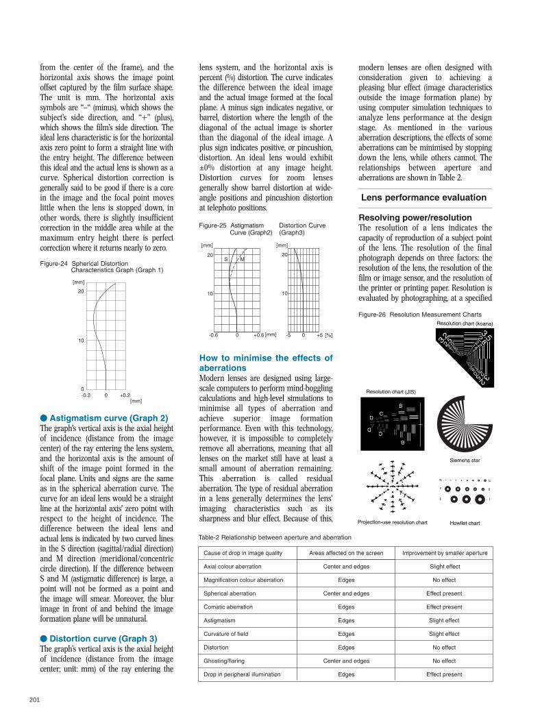
from the center of the frame), and thehorizontal axis shows the image pointoffset captured by the film surface shape.The unit is mm. The horizontal axissymbols are “—“ (minus), which shows thesubject’s side direction, and “+” (plus),which shows the film’s side direction. Theideal lens characteristic is for the horizontalaxis zero point to form a straight line withthe entry height. The difference betweenthis ideal and the actual lens is shown as acurve. Spherical distortion correction isgenerally said to be good if there is a corein the image and the focal point moveslittle when the lens is stopped down, inother words, there is slightly insufficientcorrection in the middle area while at themaximum entry height there is perfectcorrection where it returns nearly to zero.
V Astigmatism curve (Graph 2)The graph’s vertical axis is the axial heightof incidence (distance from the imagecenter) of the ray entering the lens system,and the horizontal axis is the amount ofshift of the image point formed in thefocal plane. Units and signs are the sameas in the spherical aberration curve. Thecurve for an ideal lens would be a straightline at the horizontal axis’ zero point withrespect to the height of incidence. Thedifference between the ideal lens andactual lens is indicated by two curved linesin the S direction (sagittal/radial direction)and M direction (meridional/concentriccircle direction). If the difference betweenS and M (astigmatic difference) is large, apoint will not be formed as a point andthe image will smear. Moreover, the blurimage in front of and behind the imageformation plane will be unnatural.
V Distortion curve (Graph 3)The graph’s vertical axis is the axial heightof incidence (distance from the imagecenter; unit: mm) of the ray entering the
lens system, and the horizontal axis ispercent (%) distortion. The curve indicatesthe difference between the ideal imageand the actual image formed at the focalplane. A minus sign indicates negative, orbarrel, distortion where the length of thediagonal of the actual image is shorterthan the diagonal of the ideal image. Aplus sign indicates positive, or pincushion,distortion. An ideal lens would exhibit±0% distortion at any image height.Distortion curves for zoom lensesgenerally show barrel distortion at wide-angle positions and pincushion distortionat telephoto positions.
How to minimise the effects ofaberrationsModern lenses are designed using large-scale computers to perform mind-bogglingcalculations and high-level simulations tominimise all types of aberration andachieve superior image formationperformance. Even with this technology,however, it is impossible to completelyremove all aberrations, meaning that alllenses on the market still have at least asmall amount of aberration remaining.This aberration is called residualaberration. The type of residual aberrationin a lens generally determines the lens’imaging characteristics such as itssharpness and blur effect. Because of this,
modern lenses are often designed withconsideration given to achieving apleasing blur effect (image characteristicsoutside the image formation plane) byusing computer simulation techniques toanalyze lens performance at the designstage. As mentioned in the variousaberration descriptions, the effects of someaberrations can be minimised by stoppingdown the lens, while others cannot. Therelationships between aperture andaberrations are shown in Table 2.
Resolving power/resolutionThe resolution of a lens indicates thecapacity of reproduction of a subject pointof the lens. The resolution of the finalphotograph depends on three factors: theresolution of the lens, the resolution of thefilm or image sensor, and the resolution ofthe printer or printing paper. Resolution isevaluated by photographing, at a specified
201
Figure-24 Spherical Distortion Characteristics Graph (Graph 1)
Figure-25 AstigmatismCurve (Graph2)
Distortion Curve(Graph3)
Lens performance evaluation
Table-2 Relationship between aperture and aberration
Figure-26 Resolution Measurement Charts
[mm]
20
10
0-0.2 +0.20
[mm]
[mm] [mm]
20
10
-0.6 +0.60
S M
[mm] -5
10
20
+50 [%]
Projection-use resolution chart Howllet chart
Resolution chart (koana)
Resolution chart (JIS)
B
CD
D
B
C
Siemens star
Cause of drop in image quality
Axial colour aberration
Magnification colour aberration
Spherical aberration
Comatic aberration
Astigmatism
Curvature of field
Distortion
Ghosting/flaring
Drop in peripheral illumination
Areas affected on the screen
Center and edges
Edges
Center and edges
Edges
Edges
Edges
Edges
Center and edges
Edges
Improvement by smaller aperture
Slight effect
No effect
Effect present
Effect present
Slight effect
Slight effect
No effect
No effect
Effect present
202
magnification, a chart containing groupsof black and white stripes that graduallydecrease in narrowness, then using amicroscope to observe the negative imageat a magnification of 50x.It is common to hear resolution expressedas a numerical value such as 50 lines or100 lines. This value indicates the numberof lines per millimeter of the smallestblack and white line pattern which can beclearly recorded on the film. To test theresolution of a lens alone, a method isused in which a fine resolution chart ispositioned in the location corresponding tothe focal plane and projected through thetest lens onto a screen. The numericalvalue used for expressing resolving poweris only an indication of the degree ofresolution possible, and does not indicateresolution clarity or contrast.
ContrastThe degree of distinction between areas ofdifferent brightness levels in a photograph,i.e., the difference in brightness betweenlight and dark areas. For example, whenthe reproduction ratio between white andblack is clear, contrast is said to be high,
and when unclear, contrast is said to below. In general, lenses producing highquality images have both high resolutionand high contrast.
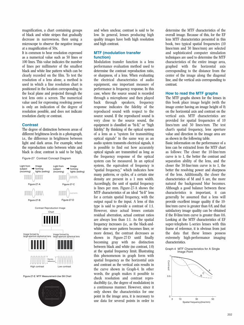
MTF (modulation transferfunction)Modulation transfer function is a lensperformance evaluation method used todetermine the contrast reproduction ratio,or sharpness, of a lens. When evaluatingthe electrical characteristics of audioequipment, one important measure ofperformance is frequency response. In thiscase, where the source sound is recordedthrough a microphone and then playedback through speakers, frequencyresponse indicates the fidelity of thereproduced sound with respect to thesource sound. If the reproduced sound isvery close to the source sound, theequipment is classified as “hi-fi,” or “highfidelity.” By thinking of the optical systemof a lens as a “system for transmittingoptical signals” in the same way as anaudio system transmits electrical signals, itis possible to find out how accuratelyoptical signals are transmitted as long asthe frequency response of the opticalsystem can be measured. In an opticalsystem, the equivalent of frequency is“spatial frequency,” which indicates howmany patterns, or cycles, of a certain sinedensity are present in a 1 mm width.Accordingly, the unit of spatial frequencyis lines per mm. Figure-27-A shows theMTF characteristics of an ideal “hi-fi” lensfor a certain spatial frequency, with theoutput equal to the input. A lens of thistype is said to provide a contrast of 1:1.However, since actual lenses containresidual aberration, actual contrast ratiosare always less than 1:1. As the spatialfrequency increases (i.e., as the black-and-white sine wave pattern becomes finer, ormore dense), the contrast decreases asshown in Figure-27-D until finallybecoming gray with no distinctionbetween black and white (no contrast, 1:0)at the spatial frequency limit. Illustratingthis phenomenon in graph form withspatial frequency as the horizontal axisand contrast as the vertical axis results inthe curve shown in Graph-4. In otherwords, the graph makes it possible tocheck resolution and contrast repro-ducibility (i,e., the degree of modulation) ina continuous manner. However, since itonly shows the characteristics for onepoint in the image area, it is necessary touse data for several points in order to
determine the MTF characteristics of theoverall image. Because of this, for the EFlens MTF characteristics presented in thisbook, two typical spatial frequencies (10lines/mm and 30 lines/mm) are selectedand sophisticated computer simulationtechniques are used to determine the MTFcharacteristics of the entire image area,graphed with the horizontal axiscorresponding to the distance from thecenter of the image along the diagonalline, and the vertical axis corresponding tocontrast.
How to read the MTF graphsThe MTF graphs shown for the lenses inthis book place image height (with theimage center having an image height of 0)on the horizontal axis and contrast on thevertical axis. MTF characteristics areprovided for spatial frequencies of 10lines/mm and 30 lines/mm. The testchart’s spatial frequency, lens aperturevalue and direction in the image area areas shown in the following table.Basic information on the performance of alens can be extracted from the MTF chartas follows: The closer the 10-line/mmcurve is to 1, the better the contrast andseparation ability of the lens, and thecloser the 30-line/mm curve is to 1, thebetter the resolving power and sharpnessof the lens. Additionally, the closer thecharacteristics of M and S are, the morenatural the background blur becomes.Although a good balance between thesecharacteristics is important, it cangenerally be assumed that a lens willprovide excellent image quality if the 10-line/mm curve is greater than 0.8, and thatsatisfactory image quality can be obtainedif the l0-line/mm curve is greater than 0.6.Looking at the MTF characteristics of EFsuper-telephoto L-series lenses with thisframe of reference, it is obvious from justthe data that these lenses possessextremely high-performance imagingcharacteristics.
Figure-27 Contrast Concept Diagram
Graph-4 MTF Characteristics for A SingleImage Point
MTF Measurement-Use Slit Chart
Light from subject (incoming)
Image forming lights (exiting)
Light from subject (incoming)
Image forming lights (exiting)
Figure-27-A
Figure-27-B
Figure-27-C
Figure-27-D
Figure-27-E
Contrast Reproduction Image
Image formed by large-aperture spherical lens
Density difference
Image formed by large-aperture aspherical lens
Chart
High contrast Low contrast
1
0.5
010 30 50
A
BC
Spatial frequency(line/mm)
Co
ntra
st
0
203
Colour balanceThe colour reproduction fidelity of a phototaken through a lens compared to theoriginal subject. Colour balance in all EFlenses is based on ISO recommendedreference values and maintained within astrict tolerance range narrower than ISO’sCCI allowable value range.→ CCI
CCI (colour contribution index)Colour reproduction in a colourphotograph depends on three factors: thecolour characteristics of the film or digitalimaging system, the colour temperature ofthe light source illuminating the subject,and the light transmission characteristics ofthe lens. The colour contribution index, orCCI, is an index indicating “the amount ofcolour variation caused by filtering effectdifferences between lenses” when using astandard film and light source, and isexpressed by three numbers in the form0/5/4. These three numbers are relativevalues expressed as logarithms of lenstransmittance at the blue-violet/green/redwavelengths corresponding to the threelight sensitive emulsion layers of colourfilm, with larger numbers representinghigher transmittance. However, sincephotographic lenses absorb mostultraviolet wavelengths, the blue-violettransmittance value is usually zero, socolour balance is judged by comparing thegreen and red values to ISO-specifiedreference lens values. The ISO referencelens light transmission characteristics wereset according to a method proposed byJapan which involved taking the averagetransmittance values of 57 standard lenses
comprising five models from representativelens manufacturers including Canon. Theresulting recommended reference value of0/5/4 is used by film manufacturers as areference when designing the colourproduction characteristics of colour films. Inother words, if the light transmissioncharacteristics of a lens do not match theISO reference values, the colourreproduction characteristics of a colour filmcannot be obtained as intended by themanufacturer.
Peripheral illuminationThe brightness of a lens is determinedby the F number, but this value only
indicates the brightness at the opticalaxis position, i.e., at the center of theimage. The brightness (image surfaceilluminance) at the edge of the image iscalled peripheral illumination and isexpressed as a percent (%) of theamount of illumination at the imagecenter. Peripheral illumination isaffected by lens vignetting and the cos4(cosine 4) law and is inevitably lowerthan the center of the image.→Vignetting, Cos4 law
Optical vignettingLight rays entering the lens from theedges of the picture area are partiallyblocked by the lens frames in front ofand behind the diaphragm, preventingall the rays from passing through theeffective aperture (diaphragm diameter)and causing light fall-off in theperipheral areas of the image. This typeof vignetting can be eliminated bystopping down the lens.
Cosine lawThe cosine law, also called the cosine law,states that light fall-off in peripheral areasof the image increases as the angle ofview increases, even if the lens iscompletely free of vignetting. The periph-eral image is formed by groups of lightrays entering the lens at a certain anglewith respect to the optical axis, and theamount of light fall-off is proportional tothe cosine of that angle raised to the
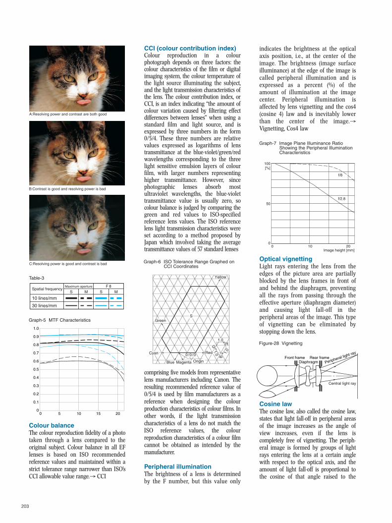
A:Resolving power and contrast are both good
B:Contrast is good and resolving power is bad
C:Resolving power is good and contrast is bad
Table-3
Graph-5 MTF Characteristics
Graph-7 Image Plane Illuminance RatioShowing the Peripheral IlluminationCharacteristics
Graph-6 ISO Tolerance Range Graphed onCCI Coordinates
Figure-28 Vignetting
10 lines/mm
Spatial frequencyMaximum aperture F 8
MSMS
30 lines/mm
0 5 10 15 20
1.0
0.9
0.8
0.7
0.6
0.5
0.4
0.3
0.2
0.1
0
Yellow
Green
Cyan
1.0
Red
Origin
0/0/0
Blue Magenta
R
S
B
G
1.01.0
100
50
00 10
f/8
20Image height [mm]
[%]
f/2.8
Front frame Rear frameDiaphragm Peripheral light ray
Central light ray
204
fourth power. As this is a law of physics, itcannot be avoided. However, with wide-angle lenses having a large angle of view,decreases in peripheral illumination canbe prevented by increasing the lens’aperture efficiency (ratio of the area of theon-axis entrance pupil to the area of theoff-axis entrance pupil).
Hard vignettingA phenomenon where light entering thelens is partially blocked by anobstruction such as the end of a lenshood or the frame of a filter, causingthe corners of the image to darken orthe overall image to lighten. Shading isthe general term used for the casewhere the image is degraded by sometype of obstacle that blocks light rayswhich should actually reach the image.
FlareLight reflected from lens surfaces, theinside of the lens barrel and the innerwalls of the camera’s mirror box can reachthe film or image sensor and fog part orall of the image area, degrading imagesharpness. These harmful reflections arecalled flare. Although flare can be reducedto a large extent by coating the lenssurfaces and using anti-reflectionmeasures in the lens barrel and camera,flare cannot be completely eliminated forall subject conditions. It is therefore
desirable to use an appropriate lens hoodwhenever possible. The term “flare” is alsoused when referring to the effects ofblurring and halo caused by spherical andcomatic aberration.
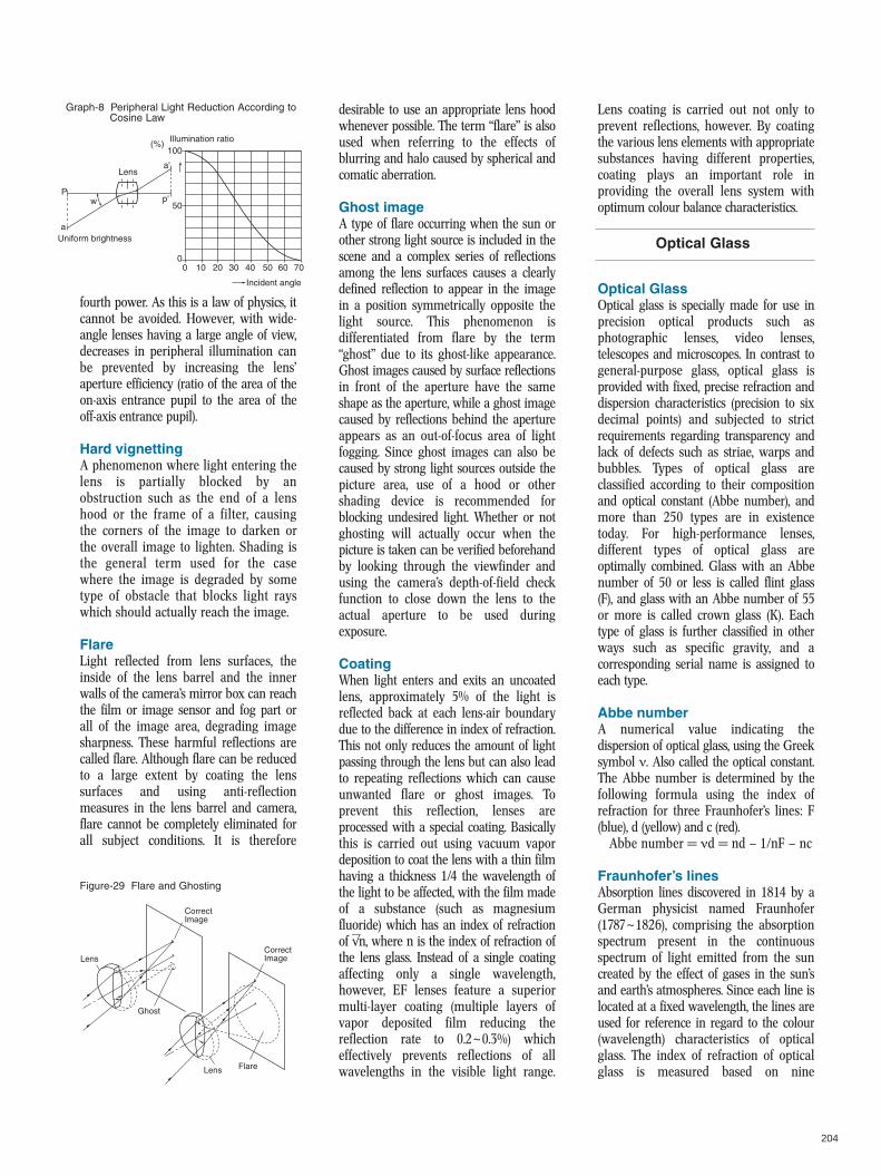
Ghost imageA type of flare occurring when the sun orother strong light source is included in thescene and a complex series of reflectionsamong the lens surfaces causes a clearlydefined reflection to appear in the imagein a position symmetrically opposite thelight source. This phenomenon isdifferentiated from flare by the term“ghost” due to its ghost-like appearance.Ghost images caused by surface reflectionsin front of the aperture have the sameshape as the aperture, while a ghost imagecaused by reflections behind the apertureappears as an out-of-focus area of lightfogging. Since ghost images can also becaused by strong light sources outside thepicture area, use of a hood or othershading device is recommended forblocking undesired light. Whether or notghosting will actually occur when thepicture is taken can be verified beforehandby looking through the viewfinder andusing the camera’s depth-of-field checkfunction to close down the lens to theactual aperture to be used duringexposure.
CoatingWhen light enters and exits an uncoatedlens, approximately 5% of the light isreflected back at each lens-air boundarydue to the difference in index of refraction.This not only reduces the amount of lightpassing through the lens but can also leadto repeating reflections which can causeunwanted flare or ghost images. Toprevent this reflection, lenses areprocessed with a special coating. Basicallythis is carried out using vacuum vapordeposition to coat the lens with a thin filmhaving a thickness 1/4 the wavelength ofthe light to be affected, with the film madeof a substance (such as magnesiumfluoride) which has an index of refractionof √ n, where n is the index of refraction ofthe lens glass. Instead of a single coatingaffecting only a single wavelength,however, EF lenses feature a superiormulti-layer coating (multiple layers ofvapor deposited film reducing thereflection rate to 0.2~0.3%) whicheffectively prevents reflections of allwavelengths in the visible light range.
Lens coating is carried out not only toprevent reflections, however. By coatingthe various lens elements with appropriatesubstances having different properties,coating plays an important role inproviding the overall lens system withoptimum colour balance characteristics.
Optical GlassOptical glass is specially made for use inprecision optical products such asphotographic lenses, video lenses,telescopes and microscopes. In contrast togeneral-purpose glass, optical glass isprovided with fixed, precise refraction anddispersion characteristics (precision to sixdecimal points) and subjected to strictrequirements regarding transparency andlack of defects such as striae, warps andbubbles. Types of optical glass areclassified according to their compositionand optical constant (Abbe number), andmore than 250 types are in existencetoday. For high-performance lenses,different types of optical glass areoptimally combined. Glass with an Abbenumber of 50 or less is called flint glass(F), and glass with an Abbe number of 55or more is called crown glass (K). Eachtype of glass is further classified in otherways such as specific gravity, and acorresponding serial name is assigned toeach type.
Abbe numberA numerical value indicating thedispersion of optical glass, using the Greeksymbol ν. Also called the optical constant.The Abbe number is determined by thefollowing formula using the index ofrefraction for three Fraunhofer’s lines: F(blue), d (yellow) and c (red).
Abbe number = νd = nd — 1/nF — nc
Fraunhofer’s linesAbsorption lines discovered in 1814 by aGerman physicist named Fraunhofer(1787~1826), comprising the absorptionspectrum present in the continuousspectrum of light emitted from the suncreated by the effect of gases in the sun’sand earth’s atmospheres. Since each line islocated at a fixed wavelength, the lines areused for reference in regard to the colour(wavelength) characteristics of opticalglass. The index of refraction of opticalglass is measured based on nine
Graph-8 Peripheral Light Reduction According toCosine Law
Optical Glass
Figure-29 Flare and Ghosting
Illumination ratio
Uniform brightness
Lens
wP
a
a'
p'
100(%)
50
00 10 20 30 40 50 60 70
Incident angle
Correct Image
Correct Image
FlareLens
Lens
Ghost

205
wavelengths selected from amongFraunhofer’s lines (see Table 4). In lensdesign, calculations for correctingchromatic aberrations are also based onthese wavelengths.
FluoriteFluorite has extremely low indexes ofrefraction and dispersion compared tooptical glass and features special partialdispersion characteristics (extraordinarypartial dispersion), enabling virtually idealcorrection of chromatic aberrations whencombined with optical glass. This fact haslong been known, and in 1880 naturalfluorite was already in practical use in theapochromatic objective lenses of micro-scopes. However, since natural fluoriteexists only in small pieces, it cannot beused practically in photographic lenses. Inanswer to this problem, Canon in 1968succeeded in establishing productiontechnology for manufacturing largeartificial crystals, thus opening the door forfluorite use in photographic lenses.
UD lensA lens made of special optical glasspossessing optical characteristics similar tofluorite. UD lens elements are especiallyeffective in correcting chromatic aberra-tions in super-telephoto lenses. Two UDlens elements are characteristicallyequivalent to one fluorite element. “UD”stands for “ultra-low dispersion.”
Lead-Free GlassThis is a type of optical glass whichcontains no lead, to relieve the burden onthe environment. Lead is used in manytypes of optical glass because it raises therefractive power of glass. While the leadcannot leak out of the glass it is containedin, it does nevertheless pose a threat to theenvironment when it escapes in the formof waste produced when grinding andpolishing the glass. With the goal ofeliminating lead from the manufacturingprocess, Canon worked with a glass
manufacturer to develop lead free glass,and is in the process of phasing out glasswhich contains lead from its lens lineup.Lead free glass uses titanium, which,unlike lead, poses no problems for theenvironment or humans, but still deliversoptical characteristics equal toconventional leaded glass.
Lens shapes
Fresnel lensA type of converging lens, formed byfinely dividing the convex surface of a flatconvex lens into many concentric circle-shaped ring lenses and combining them toextremely reduce the thickness of the lenswhile retaining its function as convex lens.In an SLR, to efficiently direct peripheraldiffused light to the eyepiece, the sideopposite the matte surface of the focusingscreen is formed as a fresnel lens with a0.05 mm pitch Fresnel lenses are alsocommonly used in flash units, indicatedby the concentric circular lines visible onthe white diffusion screen covering theflash tube. The projection lens used toproject light from a lighthouse is anexample of a giant fresnel lens.
Aspherical lensPhotographic lenses are generallyconstructed of several single lens elements,all of which, unless otherwise specified,have spherical surfaces. Because allsurfaces are spherical, it becomesespecially difficult to correct sphericalaberration in large-aperture lenses anddistortion in super-wide-angle lenses. A
special lens element with a surface curvedwith the ideal shape to correct theseaberrations, i.e., a lens having a free-curvedsurface which is not spherical, is called anaspherical lens. The theory and usefulnessof aspherical lenses. have been knownsince the early days of lens making, butdue to the extreme difficulty of actuallyprocessing and accurately measuringaspherical surfaces, practical asphericallens manufacturing methods were notrealised until fairly recently. The first SLRphotographic lens to incorporate a largediameter aspherical lens was Canon’sFD 55mm f/1.2AL released in March 1971.Due to revolutionary advances inproduction technology since that time,Canon’s current EF lens group makesabundant use of various aspherical lenstypes such as ground and polished glassaspherical lens elements, ultra-precisionglass molded (GMo) aspherical lenselements, composite aspherical lenselements and replica aspherical lenselements.
Air lensThe air spaces between the glass lenselements making up a photographic lenscan be thought of as lenses made of glasshaving the same index of refraction as air(1.0). An air space designed from thebeginning with this concept in mind iscalled an air lens. Since the refraction ofan air lens is opposite that of a glass lens,a convex shape acts as a concave lens anda concave shape acts as a convex lens.This principle was first propounded in1898 by a man named Emil von Hoeghworking for the German company Goerz.
Actual photographic lensesWhen looking at the enlarged image of anobject through a magnifying glass, it iscommon for the edges of the image to bedistorted or discoloured even if the centeris clear. As this indicates, a single-elementlens suffers from many types of aberra-tions and cannot reproduce an imagewhich is clearly defined from corner tocorner. Because of this, photographiclenses are constructed of several lenselements having different shapes andcharacteristics in order to obtain a sharp
Table-4 Light Wavelengths and SpectrumLines
Lens shapes and lens construction fundamentals
Figure-32 Air Lens Concept Diagram
Figure-31 Fresnel Lens
Figure-30 Lens Shapes
Note: 1 nm = 10-6mm
Spectrumline code
Wavelength (mm)
Colour
i
365,0
Ultra-violet
h
404,7
Violet
g
435,8
Blue-violet
F
486,1
Blue
e
546,1
Green
d
587,6
Yellow
c
656,3
Red
r
706,5
Red
t
1014
Infrared
Spectrumline code
Wavelength (mm)
Colour Plane-convex lens Biconvex lenses Convex meniscus lens
Plane-concave lenses Biconcave lens Concave meniscus lens
M L H
↑L (air space)
MH
206
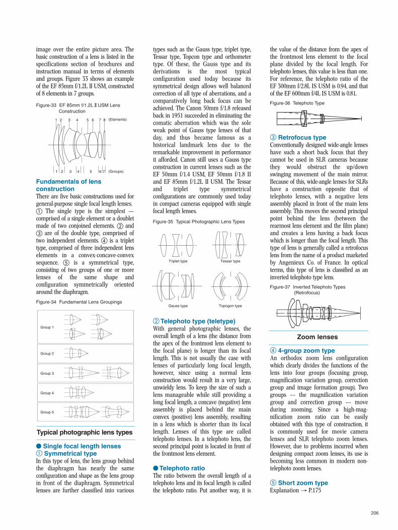
image over the entire picture area. Thebasic construction of a lens is listed in thespecifications section of brochures andinstruction manual in terms of elementsand groups. Figure 33 shows an exampleof the EF 85mm f/1.2L II USM, constructedof 8 elements in 7 groups.
Fundamentals of lensconstructionThere are five basic constructions used forgeneral-purpose single focal length lenses.a The single type is the simplest ——comprised of a single element or a doubletmade of two conjoined elements. b andc are of the double type, comprised oftwo independent elements. d is a triplettype, comprised of three independent lenselements in a convex-concave-convexsequence. e is a symmetrical type,consisting of two groups of one or morelenses of the same shape andconfiguration symmetrically orientedaround the diaphragm.
V Single focal length lensesa Symmetrical typeIn this type of lens, the lens group behindthe diaphragm has nearly the sameconfiguration and shape as the lens groupin front of the diaphragm. Symmetricallenses are further classified into various
types such as the Gauss type, triplet type,Tessar type, Topcon type and orthometertype. Of these, the Gauss type and itsderivations is the most typicalconfiguration used today because itssymmetrical design allows well balancedcorrection of all type of aberrations, and acomparatively long back focus can beachieved. The Canon 50mm f/1.8 releasedback in 1951 succeeded in eliminating thecomatic aberration which was the soleweak point of Gauss type lenses of thatday, and thus became famous as ahistorical landmark lens due to theremarkable improvement in performanceit afforded. Canon still uses a Gauss typeconstruction in current lenses such as theEF 50mm f/1.4 USM, EF 50mm f/1.8 IIand EF 85mm f/1.2L II USM. The Tessarand triplet type symmetricalconfigurations are commonly used todayin compact cameras equipped with singlefocal length lenses.
b Telephoto type (teletype)With general photographic lenses, theoverall length of a lens (the distance fromthe apex of the frontmost lens element tothe focal plane) is longer than its focallength. This is not usually the case withlenses of particularly long focal length,however, since using a normal lensconstruction would result in a very large,unwieldy lens. To keep the size of such alens manageable while still providing along focal length, a concave (negative) lensassembly is placed behind the mainconvex (positive) lens assembly, resultingin a lens which is shorter than its focallength. Lenses of this type are calledtelephoto lenses. In a telephoto lens, thesecond principal point is located in front ofthe frontmost lens element.
V Telephoto ratioThe ratio between the overall length of atelephoto lens and its focal length is calledthe telephoto ratio. Put another way, it is
the value of the distance from the apex ofthe frontmost lens element to the focalplane divided by the focal length. Fortelephoto lenses, this value is less than one.For reference, the telephoto ratio of theEF 300mm f/2.8L IS USM is 0.94, and thatof the EF 600mm f/4L IS USM is 0.81.
c Retrofocus typeConventionally designed wide-angle lenseshave such a short back focus that theycannot be used in SLR cameras becausethey would obstruct the up/downswinging movement of the main mirror.Because of this, wide-angle lenses for SLRshave a construction opposite that oftelephoto lenses, with a negative lensassembly placed in front of the main lensassembly. This moves the second principalpoint behind the lens (between therearmost lens element and the film plane)and creates a lens having a back focuswhich is longer than the focal length. Thistype of lens is generally called a retrofocuslens from the name of a product marketedby Angenieux Co. of France. In opticalterms, this type of lens is classified as aninverted telephoto type lens.
d 4-group zoom typeAn orthodox zoom lens configurationwhich clearly divides the functions of thelens into four groups (focusing group,magnification variation group, correctiongroup and image formation group). Twogroups –– the magnification variationgroup and correction group –– moveduring zooming. Since a high-mag-nification zoom ratio can be easilyobtained with this type of construction, itis commonly used for movie cameralenses and SLR telephoto zoom lenses.However, due to problems incurred whendesigning compact zoom lenses, its use isbecoming less common in modern non-telephoto zoom lenses.
e Short zoom typeExplanation → P.175
Figure-33 EF 85mm f/1.2L@USM LensConstruction
Figure-36 Telephoto Type
Figure-35 Typical Photographic Lens Types
Figure-37 Inverted Telephoto Types(Retrofocus)
Figure-34 Fundamental Lens Groupings
Typical photographic lens types
Zoom lenses
1 2 3 4 5 6 7 8
1 2 3 4 5 6 7
(Elements)
(Groups)
Group 1
Group 2
Group 3
Group 4
Group 5
Triplet type Tessar type
Gauss type Topogon type
207
f Multi-group zoom typeExplanation → P.175
Focusing and lens movementtechniquesMethods of lens movement for focusingcan be broadly classified into the fivetypes described below.
a Overall linear extensionThe entire lens optical system movesstraight backward and forward whenfocusing is carried out. This is the simplesttype of focusing used in mainly in wide-angle through standard single focal lengthlenses, Such as the EF 15mm f/2.8Fisheye, lense, the EF 50mm f/1.4 USM,the TS-E 90mm f/2.8, and other EF lenses.
b Front group linear extensionThe rear group remains fixed and only thefront group moves straight backward andforward during focusing. Examples offront group linear extension lenses are theEF 50mm f/2.5 Compact Macro, MP-E 65mm f/2.8 Macro Photo andEF 85mm f/1.2L II USM.
c Front group rotational extensionThe lens barrel section holding the frontlens group rotates to move the front groupbackward and forward during focusing.This type of focusing is used only in zoomlenses and is not found in single focallength lenses. Representative examples oflenses using this method are the EF 28-90mm f/4-5.6 III, EF 75-300mm f/4-5.6 ISUSM and EF 90-300mm f/4.5-5.6 USMand other EF lenses.
d Inner focusingFocusing is performed by moving one ormore lens groups positioned between thefront lens group and the diaphragm. → P.176
e Rear focusingFocusing is performed by moving one ormore lens groups positioned behind thediaphragm. → P.177
Floating systemThis system varies the interval betweencertain lens elements in accordance withthe extension amount in order to com-pensate for aberration fluctuation causedby camera distance. This method is alsoreferred to as a close-distance aberrationcompensation mechanism. → P.177
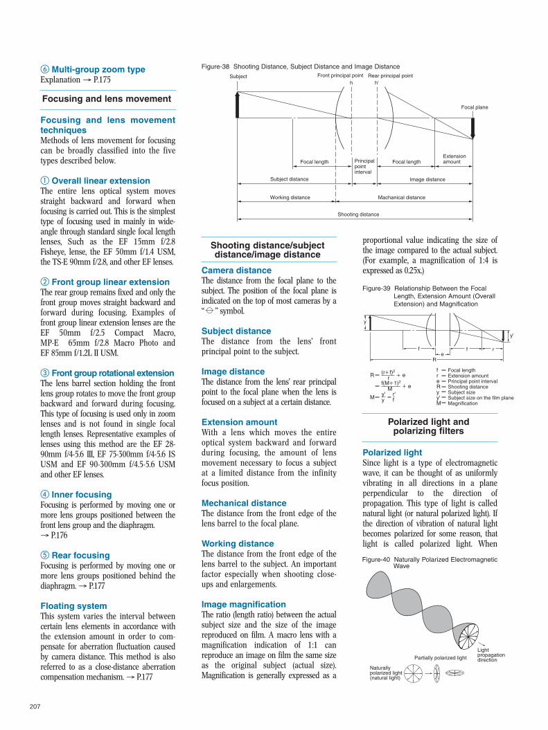
Camera distanceThe distance from the focal plane to thesubject. The position of the focal plane isindicated on the top of most cameras by a“ ” symbol.
Subject distanceThe distance from the lens’ frontprincipal point to the subject.
Image distanceThe distance from the lens’ rear principalpoint to the focal plane when the lens isfocused on a subject at a certain distance.
Extension amountWith a lens which moves the entireoptical system backward and forwardduring focusing, the amount of lensmovement necessary to focus a subjectat a limited distance from the infinityfocus position.
Mechanical distanceThe distance from the front edge of thelens barrel to the focal plane.
Working distanceThe distance from the front edge of thelens barrel to the subject. An importantfactor especially when shooting close-ups and enlargements.
Image magnificationThe ratio (length ratio) between the actualsubject size and the size of the imagereproduced on film. A macro lens with amagnification indication of 1:1 canreproduce an image on film the same sizeas the original subject (actual size).Magnification is generally expressed as a
proportional value indicating the size ofthe image compared to the actual subject.(For example, a magnification of 1:4 isexpressed as 0.25x.)
Polarized lightSince light is a type of electromagneticwave, it can be thought of as uniformlyvibrating in all directions in a planeperpendicular to the direction ofpropagation. This type of light is callednatural light (or natural polarized light). Ifthe direction of vibration of natural lightbecomes polarized for some reason, thatlight is called polarized light. When
Focusing and lens movement
Figure-38 Shooting Distance, Subject Distance and Image Distance
Shooting distance/subject distance/image distance
Figure-39 Relationship Between the FocalLength, Extension Amount (OverallExtension) and Magnification
Polarized light andpolarizing filters
Figure-40 Naturally Polarized ElectromagneticWave
Subject Front principal point
Focal lengthFocal length
Rear principal point
Image distance
Shooting distance
Subject distance
Working distance Machanical distance
Extension amountPrincipal
point interval
Focal plane
h h'
rfreRyy'M
Focal length Extension amount Principal point interval Shooting distance Subject size Subject size on the film plane Magnification
R (r f)2e
M
M
f(M 1)2
y'y
y
f f r
y'
eR
r'f
e
Naturally polarized light (natural light)
Partially polarized light
Light propagation direction
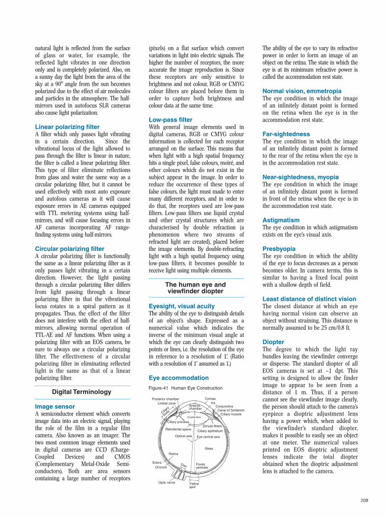
208
natural light is reflected from the surfaceof glass or water, for example, thereflected light vibrates in one directiononly and is completely polarized. Also, ona sunny day the light from the area of thesky at a 90° angle from the sun becomespolarized due to the effect of air moleculesand particles in the atmosphere. The half-mirrors used in autofocus SLR camerasalso cause light polarization.
Linear polarizing filterA filter which only passes light vibratingin a certain direction. Since thevibrational locus of the light allowed topass through the filter is linear in nature,the filter is called a linear polarizing filter.This type of filter eliminate reflectionsfrom glass and water the same way as acircular polarizing filter, but it cannot beused effectively with most auto exposureand autofous cameras as it will causeexposure errors in AE cameras equippedwith TTL metering systems using half-mirrors, and will cause focusing errors inAF cameras incorporating AF range-finding systems using half-mirrors.
Circular polarizing filterA circular polarizing filter is functionallythe same as a linear polarizing filter as itonly passes light vibrating in a certaindirection. However, the light passingthrough a circular polarizing filter differsfrom light passing through a linearpolarizing filter in that the vibrationallocus rotates in a spiral pattern as itpropagates. Thus, the effect of the filterdoes not interfere with the effect of half-mirrors, allowing normal operation ofTTL-AE and AF functions. When using apolarizing filter with an EOS camera, besure to always use a circular polarizingfilter. The effectiveness of a circularpolarizing filter in eliminating reflectedlight is the same as that of a linearpolarizing filter.
Image sensorA semiconductor element which convertsimage data into an electric signal, playingthe role of the film in a regular filmcamera. Also known as an imager. Thetwo most common image elements usedin digital cameras are CCD (Charge-Coupled Devices) and CMOS(Complementary Metal-Oxide Semi-conductors). Both are area sensorscontaining a large number of receptors
(pixels) on a flat surface which convertvariations in light into electric signals. Thehigher the number of receptors, the moreaccurate the image reproduction is. Sincethese receptors are only sensitive tobrightness and not colour, RGB or CMYGcolour filters are placed before them inorder to capture both brightness andcolour data at the same time.
Low-pass filterWith general image elements used indigital cameras, RGB or CMYG colourinformation is collected for each receptorarranged on the surface. This means thatwhen light with a high spatial frequencyhits a single pixel, false colours, moiré, andother colours which do not exist in thesubject appear in the image. In order toreduce the occurrence of these types offalse colours, the light must made to entermany different receptors, and in order todo that, the receptors used are low-passfilters. Low-pass filters use liquid crystaland other crystal structures which arecharacterised by double refraction (aphenomenon where two streams ofrefracted light are created), placed beforethe image elements. By double-refractinglight with a high spatial frequency usinglow-pass filters, it becomes possible toreceive light using multiple elements.
Eyesight, visual acuityThe ability of the eye to distinguish detailsof an object’s shape. Expressed as anumerical value which indicates theinverse of the minimum visual angle atwhich the eye can clearly distinguish twopoints or lines, i.e. the resolution of the eyein reference to a resolution of 1’. (Ratiowith a resolution of 1’ assumed as 1.)
Eye accommodation
The ability of the eye to vary its refractivepower in order to form an image of anobject on the retina. The state in which theeye is at its minimum refractive power iscalled the accommodation rest state.
Normal vision, emmetropiaThe eye condition in which the imageof an infinitely distant point is formedon the retina when the eye is in theaccommodation rest state.
Far-sightednessThe eye condition in which the imageof an infinitely distant point is formedto the rear of the retina when the eye isin the accommodation rest state.
Near-sightedness, myopiaThe eye condition in which the imageof an infinitely distant point is formedin front of the retina when the eye is inthe accommodation rest state.
AstigmatismThe eye condition in which astigmatismexists on the eye’s visual axis.
PresbyopiaThe eye condition in which the abilityof the eye to focus decreases as a personbecomes older. In camera terms, this issimilar to having a fixed focal pointwith a shallow depth of field.
Least distance of distinct visionThe closest distance at which an eyehaving normal vision can observe anobject without straining. This distance isnormally assumed to be 25 cm/0.8 ft.
DiopterThe degree to which the light raybundles leaving the viewfinder convergeor disperse. The standard diopter of allEOS cameras is set at —1 dpt. Thissetting is designed to allow the finderimage to appear to be seen from adistance of 1 m. Thus, if a personcannot see the viewfinder image clearly,the person should attach to the camera’seyepiece a dioptric adjustment lenshaving a power which, when added tothe viewfinder’s standard diopter,makes it possible to easily see an objectat one meter. The numerical valuesprinted on EOS dioptric adjustmentlenses indicate the total diopterobtained when the dioptric adjustmentlens is attached to the camera.
Digital TerminologyFigure-41 Human Eye Construction
The human eye andviewfinder diopter
Posterior chamberLimbal zone
Anterior chamber
Ciliary processZonule fibers
Ciliary epitheliumRetrolental space
Ciliary
body
ConjunctivaCanal of Schlemm
Ciliary muscle
Cornea
Crystal lens
Optical axis Eye central axis
Glass
Fovea centralis
Retina
Yellow spot
Optic nerve
ScleraChoroid
Disc
Iris
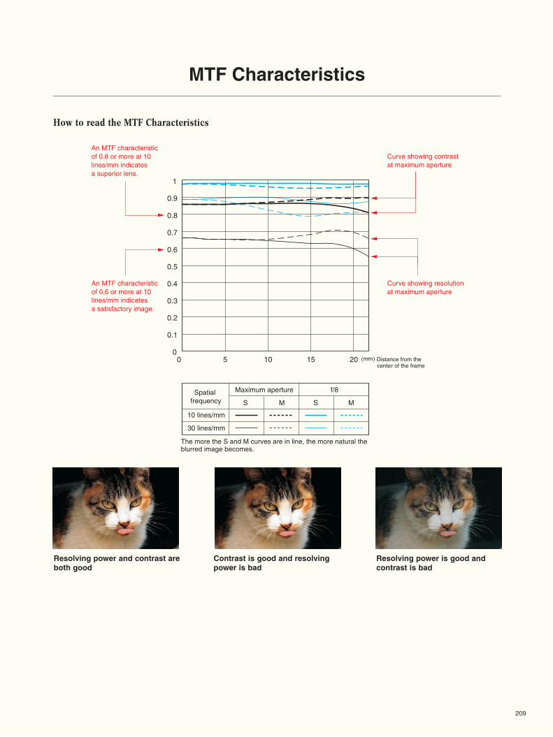
1
0.5
0
0.4
0.3
0.2
0.1
0.6
0.7
0.8
0.9
0 5 10 15 20
MTF Characteristics
Spatial �frequency
Maximum aperture f/8
S M
10 lines/mm
30 lines/mm
S M
How to read the MTF Characteristics
Curve showing resolution �at maximum aperture
Curve showing contrast �at maximum aperture
An MTF characteristic �of 0.8 or more at 10 �lines/mm indicates �a superior lens.
An MTF characteristic of 0.6 or more at 10 lines/mm indicates a satisfactory image.
The more the S and M curves are in line, the more natural the blurred image becomes.
(mm) Distance from the center of the frame
209
Resolving power and contrast are both good
Contrast is good and resolving power is bad
Resolving power is good and contrast is bad
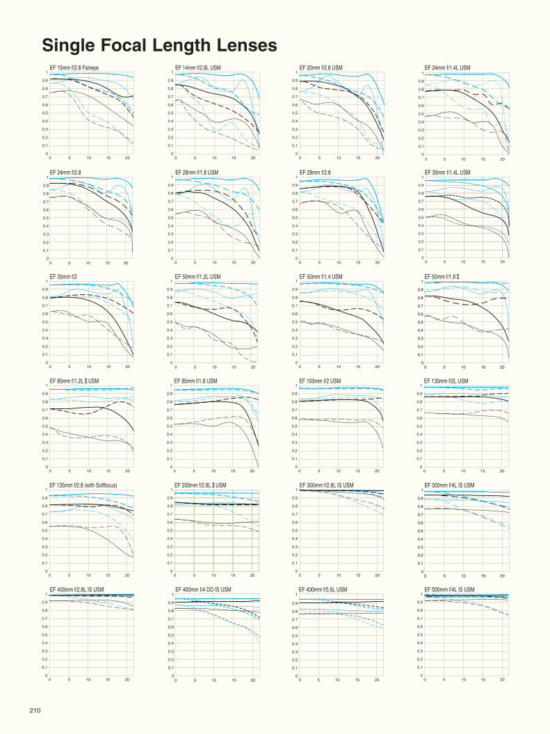
Single Focal Length LensesEF 15mm f/2.8 Fisheye EF 14mm f/2.8L USM EF 20mm f/2.8 USM EF 24mm f/1.4L USM
0 5 10 15 20
1
0.9
0.8
0.7
0.6
0.5
0.4
0.3
0.2
0.1
00 5 10 15 20
1
0.9
0.8
0.7
0.6
0.5
0.4
0.3
0.2
0.1
00 5 10 15 20
1
0.9
0.8
0.7
0.6
0.5
0.4
0.3
0.2
0.1
0
EF 24mm f/2.8 EF 28mm f/2.8 EF 35mm f/1.4L USM
0 5 10 15 20
0 5 10 15 20
1
0.9
0.8
0.7
0.6
0.5
0.4
0.3
0.2
0.1
00 5 10 15 20
1
0.9
0.8
0.7
0.6
0.5
0.4
0.3
0.2
0.1
00 5 10 15 20
1
0.9
0.8
0.7
0.6
0.5
0.4
0.3
0.2
0.1
0
EF 28mm f/1.8 USM
EF 35mm f/2 EF 50mm f/1.4 USMEF 50mm f/1.2L USM EF 50mm f/1.8@
EF 85mm f/1.2L@USM EF 85mm f/1.8 USM EF 100mm f/2 USM EF 135mm f/2L USM
EF 135mm f/2.8 (with Softfocus) EF 200mm f/2.8L@USM
0 5 10 15 20
1
0.9
0.8
0.7
0.6
0.5
0.4
0.3
0.2
0.1
0
1
0.9
0.8
0.7
0.6
0.5
0.4
0.3
0.2
0.1
00 5 10 15 20
1
0.9
0.8
0.7
0.6
0.5
0.4
0.3
0.2
0.1
0
0 5 10 15 20
1
0.9
0.8
0.7
0.6
0.5
0.4
0.3
0.2
0.1
00 5 10 15 20
1
0.9
0.8
0.7
0.6
0.5
0.4
0.3
0.2
0.1
00 5 10 15 20
1
0.9
0.8
0.7
0.6
0.5
0.4
0.3
0.2
0.1
00 5 10 15 20
1
0.9
0.8
0.7
0.6
0.5
0.4
0.3
0.2
0.1
0
0 5 10 15 20
1
0.9
0.8
0.7
0.6
0.5
0.4
0.3
0.2
0.1
0
EF 300mm f/2.8L IS USM EF 300mm f/4L IS USM
EF 400mm f/2.8L IS USM
0 5 10 15 20
1
0.9
0.8
0.7
0.6
0.5
0.4
0.3
0.2
0.1
00 5 10 15 20
1
0.9
0.8
0.7
0.6
0.5
0.4
0.3
0.2
0.1
0
0 5 10 15 20
1
0.9
0.8
0.7
0.6
0.5
0.4
0.3
0.2
0.1
0
EF 400mm f/5.6L USM 1
0.5
0
0.4
0.3
0.2
0.1
0.6
0.7
0.8
0.9
0 5 10 15 20
EF 400mm f/4 DO IS USM1
0.5
0
0.4
0.3
0.2
0.1
0.6
0.7
0.8
0.9
0 5 10 15 20
EF 500mm f/4L IS USM
0 5 10 15 20
1
0.9
0.8
0.7
0.6
0.5
0.4
0.3
0.2
0.1
0
1
0.5
0
0.4
0.3
0.2
0.1
0.6
0.7
0.8
0.9
0 5 10 15 20
1
0.5
0
0.4
0.3
0.2
0.1
0.6
0.7
0.8
0.9
0 5 10 15 20
1
0.5
0
0.4
0.3
0.2
0.1
0.6
0.7
0.8
0.9
0 5 10 15 20
0 5 10 15 20
1
0.9
0.8
0.7
0.6
0.5
0.4
0.3
0.2
0.1
0
210
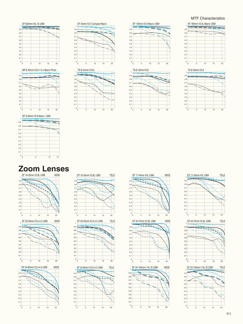
MTF CharacteristicsEF 50mm f/2.5 Compact Macro EF 100mm f/2.8 Macro USM EF 180mm f/3.5L Macro USM
0 5 10 15 20
1
0.9
0.8
0.7
0.6
0.5
0.4
0.3
0.2
0.1
00 5 10 15 20
1
0.9
0.8
0.7
0.6
0.5
0.4
0.3
0.2
0.1
00 5 10 15 20
1
0.9
0.8
0.7
0.6
0.5
0.4
0.3
0.2
0.1
0
MP-E 65mm f/2.8 1-5 x Macro Photo TS-E 24mm f/3.5L TS-E 45mm f/2.8 TS-E 90mm f/2.8
0 5 10 15 20
1
0.9
0.8
0.7
0.6
0.5
0.4
0.3
0.2
0.1
00 5 10 15 20
1
0.9
0.8
0.7
0.6
0.5
0.4
0.3
0.2
0.1
00 5 10 15 20
1
0.9
0.8
0.7
0.6
0.5
0.4
0.3
0.2
0.1
00 5 10 15 20
1
0.9
0.8
0.7
0.6
0.5
0.4
0.3
0.2
0.1
0
EF-S 60mm f/2.8 Macro USM1
0.5
0
0.4
0.3
0.2
0.1
0.6
0.7
0.8
0.9
0 5 10 13
EF 600mm f/4L IS USM
0 5 10 15 20
1
0.9
0.8
0.7
0.6
0.5
0.4
0.3
0.2
0.1
0
EF 20-35mm f/3.5-4.5 USM WIDE EF 20-35mm f/3.5-4.5 USM TELE
0 5 10 15 20
1
0.9
0.8
0.7
0.6
0.5
0.4
0.3
0.2
0.1
00 5 10 15 20
1
0.9
0.8
0.7
0.6
0.5
0.4
0.3
0.2
0.1
0
EF 24-70mm f/2.8L USM WIDE EF 24-70mm f/2.8L USM TELE1
0.5
0
0.4
0.3
0.2
0.1
0.6
0.7
0.8
0.9
0 5 10 15 20
1
0.5
0
0.4
0.3
0.2
0.1
0.6
0.7
0.8
0.9
0 5 10 15 20
EF 16-35mm f/2.8L USM WIDE EF 16-35mm f/2.8L USM TELE EF 17-40mm f/4L USM WIDE EF 17-40mm f/4L USM TELE EF 135mm f/2L USMEF135mm f/2L USM1
0.5
0
0.4
0.3
0.2
0.1
0.6
0.7
0.8
0.9
0 5 10 15 20
1
0.5
0
0.4
0.3
0.2
0.1
0.6
0.7
0.8
0.9
0 5 10 15 20
1
0.5
0
0.4
0.3
0.2
0.1
0.6
0.7
0.8
0.9
0 5 10 15 20
1
0.5
0
0.4
0.3
0.2
0.1
0.6
0.7
0.8
0.9
0 5 10 15 20
EF 24-85mm f/3.5-4.5 USM TELE1
0.5
0
0.4
0.3
0.2
0.1
0.6
0.7
0.8
0.9
0 5 10 15 20
EF 24-85mm f/3.5-4.5 USM WIDE1
0.5
0
0.4
0.3
0.2
0.1
0.6
0.7
0.8
0.9
0 5 10 15 20
EF 24-105mm f /4L IS USM WIDE
0 5 10 15 20
1
0.9
0.8
0.7
0.6
0.5
0.4
0.3
0.2
0.1
0
EF 24-105mm f /4L IS USM TELE1
0.5
0
0.4
0.3
0.2
0.1
0.6
0.7
0.8
0.9
0 5 10 15 20
Zoom Lenses
211
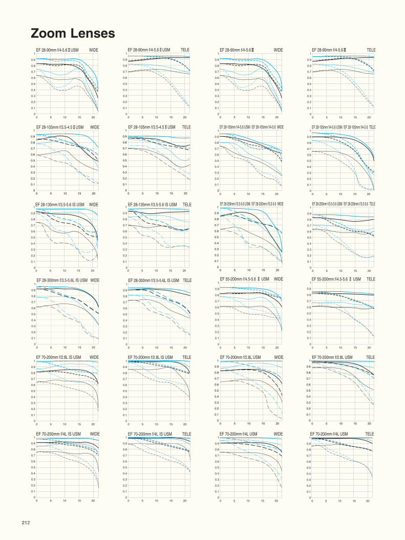
212
Zoom Lenses
EF 55-200mm f/4.5-5.6 @ USM WIDE1
0.5
0
0.4
0.3
0.2
0.1
0.6
0.7
0.8
0.9
0 5 10 15 20
EF 55-200mm f/4.5-5.6 @ USM TELE1
0.5
0
0.4
0.3
0.2
0.1
0.6
0.7
0.8
0.9
0 5 10 15 20
EF 70-200mm f/2.8L IS USM TELE1
0.5
0
0.4
0.3
0.2
0.2
0.1
0.6
0.7
0.8
0.9
0 5 10 15 20
EF 70-200mm f/2.8L IS USM WIDE
EF 70-200mm f/4L IS USM TELEEF 70-200mm f/4L IS USM WIDE
1
0.5
0
0.4
0.3
0.2
0.1
0.6
0.7
0.8
0.9
0 5 10 15 20
1
0.5
0
0.4
0.3
0.1
0.6
0.7
0.8
0.9
0 5 10 15 20
1
0.5
0
0.4
0.3
0.2
0.1
0.6
0.7
0.8
0.9
0 5 10 15 20
EF 28-300mm f/3.5-5.6L IS USM WIDE1
0.5
0
0.4
0.3
0.2
0.1
0.6
0.7
0.8
0.9
0 5 10 15 20
EF 28-300mm f/3.5-5.6L IS USM TELE1
0.5
0
0.4
0.3
0.2
0.1
0.6
0.7
0.8
0.9
0 5 10 15 20
EF 28-90mm f/4-5.6@USM WIDE1
0.5
0
0.4
0.3
0.2
0.1
0.6
0.7
0.8
0.9
0 5 10 15 20
EF 28-90mm f/4-5.6@USM TELE1
0.5
0
0.4
0.3
0.2
0.1
0.6
0.7
0.8
0.9
0 5 10 15 20
EF 28-90mm f/4-5.6# WIDE1
0.5
0
0.4
0.3
0.2
0.1
0.6
0.7
0.8
0.9
0 5 10 15 20
EF 28-90mm f/4-5.6# TELE1
0.5
0
0.4
0.3
0.2
0.1
0.6
0.7
0.8
0.9
0 5 10 15 20
EF 28-105mm f/3.5-4.5@USM WIDE
0 5 10 15 20
1
0.9
0.8
0.7
0.6
0.5
0.4
0.3
0.2
0.1
0
EF 28-105mm f/3.5-4.5@USM TELE
0 5 10 15 20
1
0.9
0.8
0.7
0.6
0.5
0.4
0.3
0.2
0.1
0
EF 28-105mm f/4-5.6 USM / EF 28-105mm f/4-5.6 TELE1
0.5
0
0.4
0.3
0.2
0.1
0.6
0.7
0.8
0.9
0 5 10 15 20
EF 28-105mm f/4-5.6 USM / EF 28-105mm f/4-5.6 WIDE1
0.5
0
0.4
0.3
0.2
0.1
0.6
0.7
0.8
0.9
0 5 10 15 20
EF 28-135mm f/3.5-5.6 IS USM TELE
00
0.1
0.2
0.3
0.4
0.5
0.6
0.7
0.8
0.9
1
5 10 15 20
EF 28-135mm f/3.5-5.6 IS USM WIDE
00
0.1
0.2
0.3
0.4
0.5
0.6
0.7
0.8
0.9
1
5 10 15 20
EF 28-200mm f/3.5-5.6 USM / EF 28-200mm f/3.5-5.6 TELE1
0.5
0
0.4
0.3
0.2
0.1
0.6
0.7
0.8
0.9
0 5 10 15 20
EF 28-200mm f/3.5-5.6 USM / EF 28-200mm f/3.5-5.6 WIDE
0 5 10 15 20
1
0.9
0.8
0.7
0.6
0.5
0.4
0.3
0.2
0.1
0
EF 70-200mm f/2.8L USM WIDE
0 5 10 15 20
1
0.9
0.8
0.7
0.6
0.5
0.4
0.3
0.2
0.1
0
EF 70-200mm f/2.8L USM TELE
0 5 10 15 20
1
0.9
0.8
0.7
0.6
0.5
0.4
0.3
0.2
0.1
0
EF 70-200mm f/4L USM WIDE1
0.5
0
0.4
0.3
0.2
0.1
0.6
0.7
0.8
0.9
0 5 10 15 20
EF 70-200mm f/4L USM TELE1
0.5
0
0.4
0.3
0.2
0.1
0.6
0.7
0.8
0.9
0 5 10 15 20
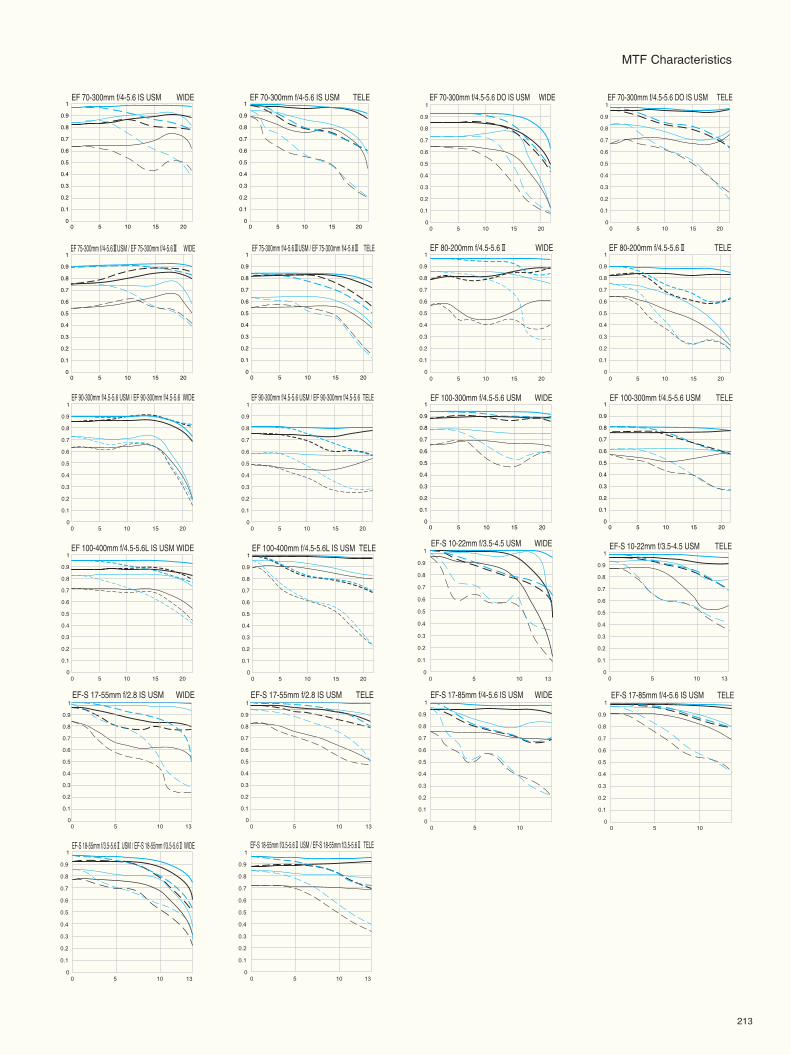
213
MTF Characteristics
EF 75-300mm f/4-5.6#USM / EF 75-300mm f/4-5.6# WIDE
0 5 10 15 20
1
0.9
0.8
0.7
0.6
0.5
0.4
0.3
0.2
0.1
0
EF 75-300mm f/4-5.6#USM / EF 75-300mm f/4-5.6# TELE
0 5 10 15 20
1
0.9
0.8
0.7
0.6
0.5
0.4
0.3
0.2
0.1
0
EF 80-200mm f/4.5-5.6@ WIDE1
0.5
0
0.4
0.3
0.2
0.1
0.6
0.7
0.8
0.9
0 5 10 15 20
EF 80-200mm f/4.5-5.6@ TELE1
0.5
0
0.4
0.3
0.2
0.1
0.6
0.7
0.8
0.9
0 5 10 15 20
EF 90-300mm f/4.5-5.6 USM / EF 90-300mm f/4.5-5.6 WIDE1
0.5
0
0.4
0.3
0.2
0.1
0.6
0.7
0.8
0.9
0 5 10 15 20
EF 90-300mm f/4.5-5.6 USM / EF 90-300mm f/4.5-5.6 TELE1
0.5
0
0.4
0.3
0.2
0.1
0.6
0.7
0.8
0.9
0 5 10 15 20
EF 100-300mm f/4.5-5.6 USM WIDE
0 5 10 15 20
1
0.9
0.8
0.7
0.6
0.5
0.4
0.3
0.2
0.1
0
EF 100-300mm f/4.5-5.6 USM TELE
0 5 10 15 20
1
0.9
0.8
0.7
0.6
0.5
0.4
0.3
0.2
0.1
0
EF 70-300mm f/4.5-5.6 DO IS USM WIDE1
0.5
0
0.4
0.3
0.2
0.1
0.6
0.7
0.8
0.9
0 5 10 15 20
EF 70-300mm f/4.5-5.6 DO IS USM TELE1
0.5
0
0.4
0.3
0.2
0.1
0.6
0.7
0.8
0.9
0 5 10 15 20
EF 100-400mm f/4.5-5.6L IS USM WIDE1
0.5
0
0.4
0.3
0.2
0.1
0.6
0.7
0.8
0.9
0 5 10 15 20
EF 100-400mm f/4.5-5.6L IS USM TELE1
0.5
0
0.4
0.3
0.2
0.1
0.6
0.7
0.8
0.9
0 5 10 15 20
EF-S 10-22mm f/3.5-4.5 USM TELE1
0.5
0
0.4
0.3
0.2
0.1
0.6
0.7
0.8
0.9
0 5 10 13
EF-S 10-22mm f/3.5-4.5 USM WIDE1
0.5
0
0.4
0.3
0.2
0.1
0.6
0.7
0.8
0.9
0 5 10 13
EF-S 18-55mm f/3.5-5.6@ USM / EF-S 18-55mm f/3.5-5.6@ WIDE1
0.5
0
0.4
0.3
0.2
0.1
0.6
0.7
0.8
0.9
0 5 10 13
EF-S 18-55mm f/3.5-5.6@ USM / EF-S 18-55mm f/3.5-5.6@ TELE1
0.5
0
0.4
0.3
0.2
0.1
0.6
0.7
0.8
0.9
0 5 10 13
EF-S 17-85mm f/4-5.6 IS USM TELE1
0.5
0
0.4
0.3
0.2
0.1
0.6
0.7
0.8
0.9
0 5 10
EF-S 17-85mm f/4-5.6 IS USM WIDEEF-S 17-55mm f/2.8 IS USM TELEEF-S 17-55mm f/2.8 IS USM WIDE1
0.5
0
0.4
0.3
0.2
0.1
0.6
0.7
0.8
0.9
0 5 10
EF 70-300mm f/4-5.6 IS USM WIDE
0 5 10 15 20
1
0.9
0.8
0.7
0.6
0.5
0.4
0.3
0.2
0.1
0
EF 70-300mm f/4-5.6 IS USM TELE
0 5 10 15 20
1
0.9
0.8
0.7
0.6
0.5
0.4
0.3
0.2
0.1
0
1
0.5
0
0.4
0.3
0.2
0.1
0.6
0.7
0.8
0.9
0 5 10 13
1
0.5
0
0.4
0.3
0.2
0.1
0.6
0.7
0.8
0.9
0 5 10 13

214
Extenders
EF 1.4x@
EF 70-200mm f/2.8L IS USM WIDE EF 70-200mm f/2.8L IS USM TELE
0 5 10 15 20
1
0.9
0.8
0.7
0.6
0.5
0.4
0.3
0.2
0.1
0
EF 70-200mm f/2.8L USM WIDE
0 5 10 15 20
1
0.9
0.8
0.7
0.6
0.5
0.4
0.3
0.2
0.1
0
EF 70-200mm f/2.8L USM TELE
0 5 10 15 20
1
0.9
0.8
0.7
0.6
0.5
0.4
0.3
0.2
0.1
0
EF 70-200mm f/4L USM WIDE
0 5 10 15 20
1
0.9
0.8
0.7
0.6
0.5
0.4
0.3
0.2
0.1
0
EF 70-200mm f/4L USM TELE
0 5 10 15 20
1
0.9
0.8
0.7
0.6
0.5
0.4
0.3
0.2
0.1
0
EF 100-400mm f/4.5-5.6L IS USM WIDE
0 5 10 15 20
1
0.9
0.8
0.7
0.6
0.5
0.4
0.3
0.2
0.1
0
EF 100-400mm f/4.5-5.6L IS USM (—:f/16) TELE
0 5 10 15 20
1
0.9
0.8
0.7
0.6
0.5
0.4
0.3
0.2
0.1
0
EF 135mm f/2L USM EF 180mm f/3.5L Macro USM
0 5 10 15 20
1
0.9
0.8
0.7
0.6
0.5
0.4
0.3
0.2
0.1
0
EF 200mm f/2.8L@USM
0 5 10 15 20
1
0.9
0.8
0.7
0.6
0.5
0.4
0.3
0.2
0.1
0
EF 300mm f/2.8L IS USM
0 5 10 15 20
1
0.9
0.8
0.7
0.6
0.5
0.4
0.3
0.2
0.1
0
EF 400mm f/2.8L IS USM
EF 400mm f/5.6L USM (—:f/16)EF 400mm f/4 DO IS USM
0 5 10 15 20
1
0.9
0.8
0.7
0.6
0.5
0.4
0.3
0.2
0.1
0
EF 500mm f/4L IS USM
0 5 10 15 20
1
0.9
0.8
0.7
0.6
0.5
0.4
0.3
0.2
0.1
0
EF 600mm f/4L IS USM
1
0.5
0
0.4
0.3
0.2
0.1
0.6
0.7
0.8
0.9
0 5 10 15 20
EF 300mm f/4L IS USM
1
0.5
0
0.4
0.3
0.2
0.1
0.6
0.7
0.8
0.9
0 5 10 15 20
1
0.5
0
0.4
0.3
0.2
0.1
0.6
0.7
0.8
0.9
0 5 10 15 20
1
0.5
0
0.4
0.3
0.2
0.1
0.6
0.7
0.8
0.9
0 5 10 15 20
1
0.5
0
0.4
0.3
0.2
0.1
0.6
0.7
0.8
0.9
0 5 10 15 20
1
0.5
0
0.4
0.3
0.2
0.1
0.6
0.7
0.8
0.9
0 5 10 15 20
EF 70-200mm f/4 IS USM WIDE EF 70-200mm f/4 IS USM TELE1
0.5
0
0.4
0.3
0.2
0.1
0.6
0.7
0.8
0.9
0 5 10 15 20
1
0.5
0
0.4
0.3
0.2
0.1
0.6
0.7
0.8
0.9
0 5 10 15 20
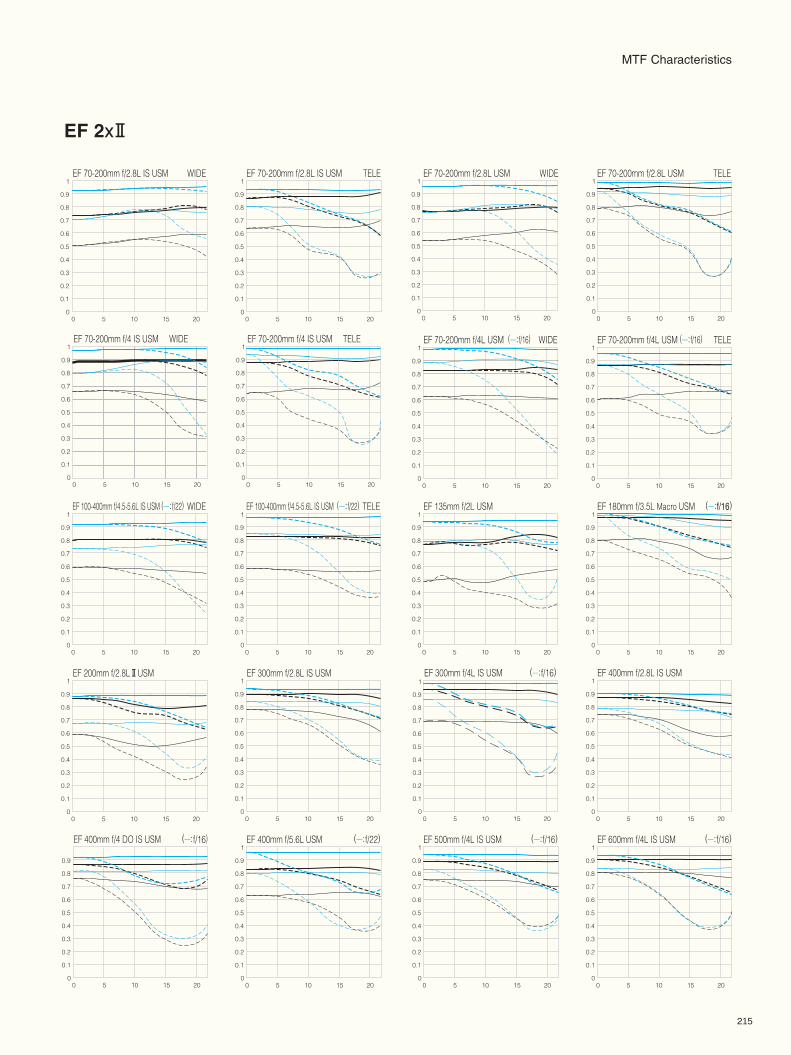
215
EF 2x@
EF 70-200mm f/2.8L USM WIDE EF 70-200mm f/2.8L USM TELEEF 70-200mm f/2.8L IS USM WIDE EF 70-200mm f/2.8L IS USM TELE
EF 70-200mm f/4L USM (—:f/16) WIDE EF 70-200mm f/4L USM (—:f/16) TELE
EF 100-400mm f/4.5-5.6L IS USM (—:f/22) WIDE EF 100-400mm f/4.5-5.6L IS USM (—:f/22) TELE EF 135mm f/2L USM EF 180mm f/3.5L Macro USM (—:f/16)
EF 200mm f/2.8L@USM EF 300mm f/2.8L IS USM EF 300mm f/4L IS USM (—:f/16) EF 400mm f/2.8L IS USM
EF 400mm f/4 DO IS USM (—:f/16) EF 400mm f/5.6L USM (—:f/22) EF 500mm f/4L IS USM (—:f/16) EF 600mm f/4L IS USM (—:f/16)
0.5
0
0.4
0.3
0.2
0.1
0.6
0.7
0.8
0.9
0 5 10 15 20
1
0.5
0
0.4
0.3
0.2
0.1
0.6
0.7
0.8
0.9
0 5 10 15 20
1
0.5
0
0.4
0.3
0.2
0.1
0.6
0.7
0.8
0.9
0 5 10 15 20
1
0.5
0
0.4
0.3
0.2
0.1
0.6
0.7
0.8
0.9
0 5 10 15 20
1
0.5
0
0.4
0.3
0.2
0.1
0.6
0.7
0.8
0.9
0 5 10 15 20
1
0.5
0
0.4
0.3
0.2
0.1
0.6
0.7
0.8
0.9
0 5 10 15 20
1
0.5
0
0.4
0.3
0.2
0.1
0.6
0.7
0.8
0.9
0 5 10 15 20
1
0.5
0
0.4
0.3
0.2
0.1
0.6
0.7
0.8
0.9
0 5 10 15 20
1
0.5
0
0.4
0.3
0.2
0.1
0.6
0.7
0.8
0.9
0 5 10 15 20
1
0.5
0
0.4
0.3
0.2
0.1
0.6
0.7
0.8
0.9
0 5 10 15 20
1
0.5
0
0.4
0.3
0.2
0.1
0.6
0.7
0.8
0.9
0 5 10 15 20
1
0.5
0
0.4
0.3
0.2
0.1
0.6
0.7
0.8
0.9
0 5 10 15 20
1
0.5
0
0.4
0.3
0.2
0.1
0.6
0.7
0.8
0.9
0 5 10 15 20
1
0.5
0
0.4
0.3
0.2
0.1
0.6
0.7
0.8
0.9
0 5 10 15 20
1
0.5
0
0.4
0.3
0.2
0.1
0.6
0.7
0.8
0.9
0 5 10 15 20
1
0.5
0
0.4
0.3
0.2
0.1
0.6
0.7
0.8
0.9
0 5 10 15 20
1
0.5
0
0.4
0.3
0.2
0.1
0.6
0.7
0.8
0.9
0 5 10 15 20
EF 70-200mm f/4 IS USM WIDE EF 70-200mm f/4 IS USM TELE1
0.5
0
0.4
0.3
0.2
0.1
0.6
0.7
0.8
0.9
0 5 10 15 20
1
0.5
0
0.4
0.3
0.2
0.1
0.6
0.7
0.8
0.9
0 5 10 15 20
1
0.5
0
0.4
0.3
0.2
0.1
0.6
0.7
0.8
0.9
0 5 10 15 20
MTF Characteristics
EF LENS WORK III The Eyes of EOS
September 2006, Eighth edition
Publisher and Planning Canon Inc. Lens Products GroupProduction and Editorial Canon Inc. Lens Products GroupPrinter Nikko Graphic Arts Co., Ltd.Thanks for the Cooperation of : Brasserie Le Solférino/Restaurant de la Maison Fouraise, Chatou/
Hippodrome de Marseille Borély/Cyrille Varet Créations, Paris/JeanPavie, artisan luthier, Paris/Participation de la Mairie de Paris/Jean-Michel OTHONIEL, sculpteur
©Canon Inc. 2003
Products and specifications are subject to change without notice.The photographs in this book are the property of Canon Inc., or used with the permission of the photographer.
CANON INC. 30-2, Shimomaruko 3-chome, Ohta-ku, Tokyo 146-8501, Japan