Opti-OWECS Final Report Vol. 1: Integrated Design ... · Integrated Design Methodology for Offshore...
102
Opti-OWECS Final Report Vol. 1: Integrated Design Methodology for Offshore Wind Energy Conversion Systems M. Kühn 1 , L.A. Harland 2 , W.A.A.M. Bierbooms 1 ,T.T. Cockerill 3 , M.C. Ferguson 4 , B. Göransson 5 , G.J.W. van Bussel 1 , J.H. Vugts 2 1 Institute for Wind Energy, Delft University of Technology, 2 Workgroup Offshore Technology, Delft University of Technology, 3 Renewable Energy Centre, University of Sunderland, 4 Kvaerner Oil & Gas Ltd., 5 Kvaerner Turbin AB Contract JOR3-CT95-0087 FINAL REPORT January 1996 to December 1997 Research funded in part by THE EUROPEAN COMMISSION in the framework of the Non Nuclear Energy Programme JOULE III
-
Upload
hoanghuong -
Category
Documents
-
view
215 -
download
0
Transcript of Opti-OWECS Final Report Vol. 1: Integrated Design ... · Integrated Design Methodology for Offshore...

Opti-OWECS Final Report Vol. 1:
Integrated Design Methodology
for Offshore Wind Energy Conversion Systems
M. Kühn 1, L.A. Harland 2, W.A.A.M. Bierbooms1,T.T. Cockerill 3, M.C. Ferguson 4,
B. Göransson 5, G.J.W. van Bussel 1, J.H. Vugts 2
1 Institute for Wind Energy, Delft University of Technology, 2 Workgroup Offshore Technology, Delft University of Technology,
3 Renewable Energy Centre, University of Sunderland, 4 Kvaerner Oil & Gas Ltd.,
5 Kvaerner Turbin AB
Contract JOR3-CT95-0087
FINAL REPORT
January 1996 to December 1997
Research funded in part by THE EUROPEAN COMMISSION
in the framework of the Non Nuclear Energy Programme
JOULE III

PUBLIC Institute for Wind Energy Faculty of Civil Engineering and Geoscience, Delft University of Technology Stevinweg 1, 2628 CN Delft, The Netherlands Report No. IW-98140R August 1998 ISBN 90-76468-02-8 Disclaimer All rights reserved.

No part of this publication may be reproduced by any means, or transmitted without written permission of the author(s). Any use or application of data, methods and/or results etc., occurring in this report will be at user's own risk. The Delft University of Technology, Faculty of Civil Engineering, Institute for Wind Energy, and the institution(s) of any other (co)author(s) accept no liability for damage suffered from the use or application. Summary In several countries of northern Europe e.g. Denmark, The Netherlands, Britain, the erection of large offshore wind farms is expected to take place by the beginning of the new millennium. The mission of this report is to propose, based upon the gained experience during the Opti-OWECS (‘Structural and Economic Optimization of Bottom-Mounted Offshore Wind Energy Converters’) project, a particular methodology, the so-called ‘integrated OWECS design approach’ in order to meet the challenge of cost-efficient and reliable offshore wind energy conversion systems (OWECS). Other suitable design methodologies undoubtedly exist, but it is expected that an OWECS design based on an ‘integrated design approach’ will most probably be nearer to optimal in both technical and economic sense. The integrated design approach considers the components of an offshore wind farm only as parts of the entire system i.e. the OWECS. Therefore interactions between sub-systems are considered as complete and practical as possible and the design solution is governed by overall criteria / aspect-systems such as: global economics, actual site conditions, entire system dynamics, structural reliability considerations, transportation / installation as well as operation and maintenance aspects. After the analysis of an OWECS system, the technologies involved and the existing experience with offshore wind farms, the approach is comprehensively described in all its details and with respect to the concerned sub-systems and phases of the design process. In addition first experience with such a methodology are presented on the background of the Opti-OWECS project and practical assistance for OWECS designer is given by means of reference appendices.

JOR3-CT95-0087 Opti-OWECS
ii
Table of contents Summary............................................................................................................................................................. iii
1. Introduction................................................................................................................................................1
1.1. Overview on the JOULE III project Opti-OWECS ..................................................1
1.2. Relation of this report to other work done within Opti-OWECS................4
1.3. Organisation of the report .....................................................................................................6
1.4. Acknowledgement........................................................................................................................7
2. OWECS life cycle ..................................................................................................................................1
3. Overall design problem..................................................................................................................1
3.1. Considerations affecting OWECS design ...................................................................1
3.1.1 Offshore wind farm system......................................................................................1
3.1.2 Social and economic factors...................................................................................2
3.1.3 Environmental and technological factors......................................................3
3.1.4 Dynamics..............................................................................................................................3
3.1.5 Structural reliability .......................................................................................................4
3.2. Design practices in wind energy and offshore technology ...........................4
3.2.1 Design of wind energy converters and wind farms................................5
3.2.2 Design of offshore structures.................................................................................5
3.3. Presently applied design approaches for OWECS...............................................6
3.3.1 Robust or traditional OWECS design approach........................................8
3.3.2 Parallel OWECS design approach .......................................................................9
3.4. Innovation by the integrated OWECS design approach.................................11
3.4.1 General principle............................................................................................................11

Integrated Design Methodology for OWECS
iii
3.4.2 Economic optimisation within the integrated approach...................12
3.4.3 Design for RAMS within the integrated approach .................................13
3.4.4 Overall OWEC dynamics within the integrated approach ...............15
3.4.5 Radical design within the integrated approach.......................................16
4. Integrated OWECS design approach...............................................................................1
4.1. Organisation of design process and design requirements ...........................1
4.2. Design process in a nutshell................................................................................................2
4.2.1 Entire design life cycle and the elementary design cycle .................2
4.2.2 Steps in the integrated OWECS design approach ...................................4
4.3. Step 0: Project identification..............................................................................................8
4.4. Step 1: Pre-selection of initial sites and design concepts...........................10
4.4.1 Step 1.1 a) Pre-selection of initial sites ........................................................10
4.4.2 Step 1.1 b) Initial selection of sub-system concepts ..........................13
4.4.3 Step 1.2: Evaluation of OWECS concepts at sites ................................13
4.4.4 Step 1.3: Selection of OWECS concepts at sites ...................................14
4.5. Step 2: Conceptual design...................................................................................................14
4.5.1 Step 2.1 a): Conceptual design of sub-systems......................................14
4.5.2 Step 2.1 b): Development of OWECS evaluation tools.......................15
4.5.3 Step 2.2: Evaluation of OWECS concepts and sites ............................15
4.5.4 Step 2.3: Selection of OWECS concepts and sites ...............................15
4.6. Step 3: Structural design ......................................................................................................16
4.6.1 Structural design of sub-systems and interaction between them........................................................................................................................................................16
4.6.2 Wind turbine design for offshore siting........................................................17
4.6.3 Design of support structure and installation procedure...................21

JOR3-CT95-0087 Opti-OWECS
iv
4.6.4 Development of grid connection ........................................................................24
4.6.5 Choice of the wind farm layout ...........................................................................26
4.6.6 Selection of operation and maintenance solution.................................28
4.7. Step 4: Design specification and preparation of construction .................29
5. First application of the integrated design approach.......................................1
6. Conclusions...............................................................................................................................................1
7. Recommendations for further development and outlook .........................1
8. References..................................................................................................................................................1
Appendix A: OWECS Terminology...........................................................................................1
Appendix B: Methods assisting the design of OWECS .....................................1
B.1. Concept analysis and cost modelling...........................................................................1
B.2. Simulation of the operational behaviour of OWECS..........................................1
B.3. Structural reliability considerations ..............................................................................2
B.4. Overall dynamics of OWEC..................................................................................................3
Appendix C: Overview on some relevant design standards and
guidelines ...........................................................................................................................................................3
Appendix D: Example database for the OWECS design process ...........1

Integrated Design Methodology for OWECS
v

JOR3-CT95-0087 Opti-OWECS
vi

Integrated Design Methodology for OWECS
-1
1. Introduction 1.1. Overview on the JOULE III project Opti-OWECS In the scope of the framework of the Non Nuclear Energy Programme JOULE III (Research and Technical Development) the European Commission supported the project 'Structural and Economic Optimisation of Bottom-Mounted Offshore Wind Energy Converters' (Opti-OWECS) under grant JOR3-CT95-0087 from January 1996 to December 1997.
Objectives of the Opti-OWECS project The particular mission of the Opti-OWECS project was to extend the state-of-the-art, to determine required methods and to demonstrate practical solutions, which significantly reduced the electricity cost. This will facilitate the commercial exploitation of true offshore sites in a medium time scale of 5 to 10 years from now. The specific objectives included:-
· A cost estimate and comparison of offshore wind energy converters of different sizes and different design concepts.
· An estimate of the cost per kWh of offshore wind energy at sites in different regions of the European Union.
· Development of methods for the simultaneous structural and economic optimisation of offshore wind energy converters with due considerations of the site characteristics.
· At least one typical design solution for a bottom-mounted offshore wind energy conversion system (OWECS).
Partnership and responsibilities
The project was an international cooperation of leading industrial engineers and researchers from the wind energy field, offshore technology and power management. The group of participants was as follows:-
· Institute for Wind Energy (IvW), Delft University of Technology(coordinator) Dutch research group active since more than 20 years in various fields of wind energy applications including major offshore wind energy research since 1992. · Kvaerner Oil & Gas, Ltd. (KOGL) Major engineering and construction company, settled in the United Kingdom, with an established track record for implementing innovative concepts for offshore oil and gas developments. · Kvaerner Turbin AB (KT)

JOR3-CT95-0087 Opti-OWECS
-2
Swedish wind turbine manufacturer with expertise in the design of multi-megawatt machines (since the 1970s) and participant in another large study on offshore wind energy (1991).
· Renewable Energy Centre, University of Sunderland (US)
British research group involved in techno-economic studies of renewable energy sources since 1978 among two major projects on wind energy costs. · Workgroup Offshore Technology (WOT), Delft University of Technology Dutch research group with particular expertise in fluid loading of offshore structures and probabilistic methods, maintaining good relations with Shell Research Rijswijk. · Energie Noord West (ENW) (sub-contractor) Dutch utility supplying 600,000 households in North-Holland and operating wind farms since more than 12 years among which the first Dutch offshore plant (Lely, 1994).
Kvaerner Oil & Gas, Ltd. and Kvaerner Turbin AB both form part of the international Kvaerner group which is organised in seven core business streams - KOGL being part of the Oil & Gas stream and KT being part of the Energy business. The role of the partners is summarised in Table 1.1-1. Partner
Role
Major scientific tasks
IvW coordinator
- general expertise on (offshore) wind energy, - overall dynamics of OWEC, - wind turbine reliability, operation & maintenance, - design of grid connection and farm layout, - assistance in the cost analysis of OWECS, - aerodynamic rotor design,
KOGL contractor
- general expertise on offshore technology, - design of support structure and installation procedure, - assistance in the cost analysis of OWECS
KT contractor
- general expertise on wind turbine technology, - adaptation of wind turbine to offshore conditions
US contractor
- concept and economic analysis of OWECS - development of cost models for OWECS, - estimate of costs of offshore wind energy at European sites
WOT contractor
- general expertise on offshore technology, - structural reliability consideration, - assistance in the cost analysis of OWECS
ENW sub- contractor
- general expertise as utility and as operator of (offshore) wind farms,

Integrated Design Methodology for OWECS
-3
(of IvW) - design of grid connection Table 1.1-1: Distribution of responsibilities among the partners

JOR3-CT95-0087 Opti-OWECS
-4
1.2. Relation of this report to other work done within Opti-OWECS
Work programme The project continued the previous work in the scope of JOUR 0072 and makes use of recent developments in wind engineering and offshore technology. The study considered the most feasible and the most probable concepts for the near future i.e. horizontal axis wind turbines rated approx. 1 - 3 MW and erected on bottom-mounted support structures in the Baltic or the North Sea. The work content of the project comprised three consecutive major tasks:-
· Task 1 Identification The main cost drivers of offshore wind energy were identified and the base case concepts and the reference sites were selected.
· Task 2 Development The economic and structural optimisation and improved design methods were developed in three parallel tasks. A cost model for manufacturing, installation and operation and maintenance of offshore wind farms was compiled. Design concepts for all main sub-systems, i.e. wind turbine, support structure, grid connection and operation and maintenance aspects, were investigated and the best combination for a certain sites was selected. Also particular design methods for OWECS such as structural reliability considerations and overall dynamics of OWEC were new developed or extended.
· Task 3 Integration In the final phase the work of the former tasks was integrated and the relationships between them were fully considered. The achieved progress was demonstrated in a typical design solution for OWECS. Moreover, energy costs at different European sites or regions were estimated in a consistent manner. The final reporting is organised in a more coherent way with a view to the subjects considered rather than in the sequence the work was carried out. Therefore the report available to the public is subdivided into six volumes:-
· Vol. 0 Executive Summary [1.1] · Vol. 1 Integrated Design Methodology for OWECS · Vol. 2 Methods Assisting the Design of OWECS [1.2] · Vol. 3 Comparison of Cost of Offshore Wind Energy at European Sites [1.3] · Vol. 4 A Typical Design Solution for an OWECS [1.4] · Vol. 5 User Guide OWECS Cost Model [1.5]
All volumes are written in such a way that is possible to review and use the volumes separately.

Integrated Design Methodology for OWECS
-5
WP 3.2 Link estimated
energy costs and European sites
WP 3.4 Final reporting
WP 2.1.3 Evaluation of
options, estimate cost of energy
WP 2.1.2 Development of the cost model
WP 2.3.2 Overall dynamics
of OWEC
WP 2.3.1 Structural reliability
considerations
WP 2.2.3 Optimisation grid connection, O&M
WP 2.2.2 Optimisation wind turbine
WP 2.2.1 Optimisation
support structure
WP 2.1.1 Full concept
analysis, data collection
WP 3.1 Link of methods
for structural and economic
optimisation
WP 3.3 Development
design solution
WP 1 Initial
concept analysis, selection of base
cases
Task 1
Task 2.1 Development of cost model, economic comparison of options
Task 3 Integration of structural and economic optimisation with design methods
Task 2.3 Improvement of design methodsTask 2.2 Structural optimisation of sub-systems
Vol. 5 User Guide for the OWECS Cost Model
Vol. 4 A Typical Design Solution for an OWECS
Vol. 3 Comparison of Cost of Offshore Wind Energy
at European Sites
Vol. 2 Methods Assisting the
Design of OWECS
Vol. 2 Methods Assisting the Design of OWECS
Vol. 1 Integrated
Design Methodology
for OWECS
WP 3.2 Link estimated
energy costs and European sites
WP 2.1.3 Evaluation of
options, estimate cost of energy
WP 2.1.2 Development of the cost model
WP 2.3.2 Overall dynamics
of OWEC
WP 2.3.1 Structural reliability
considerations
WP 2.2.3 Optimisation
grid conn., O&M
WP 2.2.2 Optimisation wind turbine
WP 2.2.1 Optimisation
support structure
WP 2.1.1 Full concept analysis, data
collection
WP 3.1 Link of methods
for structural and economic
optimisation
WP 3.3 Development
design solution
WP 1 Initial concept
analysis, selection of
base cases
Vol. 3 Comparison of Cost of Offshore Wind Energy
at European Sites

JOR3-CT95-0087 Opti-OWECS
-6
As illustrated by figure 1.2-2 the different reports cover all work packages. Since it should be possible to review and use the volumes separately, it was necessary to address some items in more than one report. However, in such a case the individual documents consider these issue from different points of view, e.g. development of cost model in Vol. 2, economic evaluation in Vol. 3 and user guide in Vol. 5. This document ‘Integrated Design Methodology for Offshore Wind Energy Conversion System’ is Volume 1 of the final report. Although this sub-report deals particularly with the work package 3.1 ‘Link of methods for structural and economic optimization’ it is the result of the two-years discussion of one of the main objectives of the entire project, i.e. to develop a methodology for the design of cost-effective and reliable offshore wind farms. The description of the OWECS design methodology in this report has been given a firm background by application of the design methodology applied for large civil works. 1.3. Organisation of the report This report comprises seven chapters and four appendices. After this introduction some remarks are given in chapter 1 on the life cycle of offshore wind energy conversion systems (OWECS). Chapter 2 analyses the design problem for OWECS and compares different solutions. This comprises a system analysis, the comparison of the design practice in offshore technology and wind energy technology, respectively and finally the description of two existing and one innovative OWECS design approach. Whilst section 3.4 introduced the novel, integrated OWECS design approach on the system level and discusses certain complementary variants, in chapter 3 the methodology is evolved in nearly all details as a kind of cook book considering also the sub-system level and all design phases. First experience with the integrated approach in a design situation is reported in chapter 4 (for more details see Vol. 4 [1.4]). Finally, conclusions and recommendations for further work are given in chapters 5 and 6, respectively. Appendix A presents an OWECS terminology developed and successfully used during the Opti-OWECS project. Next, in appendix B particular methods assisting the design of OWECS are briefly explained (full description is done by [1.2]). Appendices C and D are written as reference documents for OWECS designers including an overview of design standards (appendix C) and an example database for the OWECS design process (appendix D).
OWECS terminology Use is made of a terminology for OWECS which has been developed and successfully applied during the project (see appendix A of Vol.1 [0-2], [0-6]). In order to avoid misunderstandings there are two essential conventions that should be appreciated.

Integrated Design Methodology for OWECS
-7
Firstly, the acronym “OWECS” (standing for Offshore Wind Energy Conversion System) or its synonym “offshore wind farm” describes the entire system, that is the wind turbines, the support structures, the grid connection up to the public grid and any infrastructure for operation and maintenance. Secondly, “OWEC” (Offshore Wind Energy Converter) is used to refer to a single unit of an offshore wind farm comprising support structure (i.e. tower and foundation) and the wind turbine (i.e. aero-mechanical-electrical conversion unit on top of the tower). 1.4. Acknowledgement The comments of H.A.J. de Ridder, professor for design methodology at the Faculty of Civil Engineering of Delft University and of R. Wiecherink affiliated with Energy Noord West, Alkmaar are gratefully acknowledged.


Integrated Design Methodology for OWECS
2 - 1
2. OWECS life cycle In several countries of northern Europe e.g. Denmark, The Netherlands, Britain, the erection of large offshore wind farms is expected to take place by the beginning of the new millennium. The mission of this report is to propose a particular methodology, the so-called ‘integrated OWECS design approach’ in order to meet the challenge of cost-efficient and reliable offshore wind energy conversion systems (OWECS) (figure 2.1). Other suitable design methodologies undoubtedly exist, but it is expected that an OWECS design based on an ‘integrated design approach’ will most probably be nearer to optimal in both technical and economic sense.
Like most other products, the life cycle costs of an offshore wind farm are largely determined during the design process which itself accounts only for a relatively small portion of the investment. This obvious fact holds for an OWECS in a double manner since no fuel costs exist for this renewable energy source. Therefore the life cycle costs are mainly built up of construction and installation costs on the one hand and operation & maintenance costs on the other hand, both closely linked to the designer’s decisions. Although the rest of this report focuses on the design process, here some remarks are given on a typical life cycle of an OWECS (figure 2.2). This description is based on the evaluation of different feasibility studies and the action plans recently announced for instance in Denmark and The Netherlands [2.1], [2.2]. Moreover, experience from existing on- and offshore wind farms and offshore platforms is considered. Nonetheless, the given time scheduling (figure 2.3) especially is only of a qualitative nature due to the large influence of non-technical circumstances e.g. legal constraints, political decisions, etc.
aerodynamics
hydrodynamics
wind turbine
supportstructure
economics
wind farm
grid connection
operation & maintenance
site

JOR3-CT95-0087 Opti-OWECS
2 - 2
Between the first idea and the start of the energy generation typically some four to five years (or even more) may elapse for the three main steps: initiation, planning (i.e. design, environmental investigation and permission procedure) and building (i.e. construction, installation and commissioning). Potential delay is foreseen mainly in the permission procedure. However the site survey also may require a considerable amount of time because wind speed measurements for at least one year are required for an accurate prediction of the expected energy yield. It may also take some time before a suitably equipped vessel is available to carry out the soil investigations. The exploitation phase may typically continue for some 15 to 20 years. From an economic point of view longer periods are advantageous, however, they could be achieved even with the next generation of wind energy converters only after a refurbishment (indicated as optional in figure 2.2). In such a case the wind turbines may
Design process (incl. initiation and site selection) • Step 0: Project identification • Step 1: Feasibility study • Step 2: Conceptual design • Step 3: Structural design • Step 4: Specification
Implementation • Preparation & procurement • Construction • Installation • Commissioning
Post-Exploitation • Refurbishment (optional) • Dismantling
Permissioning • Legal constraints • Acceptance (public, interest groups) • Certification
Financing & Marketing • Financing • Power purchase negotiations
Exploitation • Operation • Maintenance
Design: Project identification Feasibility study, conceptual design Structural design, specification Site survey: desk top Site survey: in-situ ? ? ? ?Permissioning, financing, marketing ? ? ? ?Implementation: Construction Installation CommissioningExploitation (operation & maintenance)Post-Exploit.: Refurbishment (optional) Dismantlingtime 1 year 1 year 1 year 1 year 1 year 15 - 20 years 1 year 1 year 1 year
optional

Integrated Design Methodology for OWECS
2 - 3
be exchanged with a new, state-of-the-art machine whilst the support structure and the grid connection require only a major overhaul if designed for a longer lifetime. Dismantling of offshore wind energy converters, especially if based on piled steel structures, is expected to be a simple task because no major pollution or large weights are present. In case of gravity structures removing and depositing of ballast may require certain considerations. A particular property of the time scheduling that has some consequence on the design process is the seasonal dependancy of all tasks involving in-situ work i.e. site measurements, installation, commissioning, dismantling. If such activities cannot be completed within one summer season, then it will not be possible to continue until the next season.


Integrated Design Methodology for OWECS
2 - 1
3. Overall design problem 3.1. Considerations affecting OWECS design The design of an offshore wind energy conversion system should consider a number of particular properties which are characteristic to such a system. These properties will be briefly discussed in this section. 3.1.1 Offshore wind farm system
Due to high initial costs the utilization of offshore wind energy is not promising with single converter units but requires an entire offshore wind energy conversion system (OWECS). Such an offshore wind farm comprise a large number of (single) offshore wind energy converters (OWEC), the grid connection system and infrastructure facilities for operation and maintenance. Only the OWECS as one entire system can provide a considerable amount of electric power in a reliable and cost-efficient way over the projected lifetime. Therefore four objectives for an optimum OWECS design can be stated which are related to the nature of such a system:
· optimum distribution of investment and operation and maintenance (O&M) costs over the entire OWECS and its lifetime
The economics of the entire plant have to be balanced with respect to the overall operational goal, which could be the achievement of the minimum price of energy, the delivery of a certain minimum amount of energy or a combination of both. Note, such a goal cannot be reached by optimization of single sub-systems alone.
· high reliability of OWECS as a whole and of essential sub-systems A failure of a major sub-system e.g. out-of-operation of all converter units due to a design mistake or power cut-off in the grid connection system, can result in a loss of production for several months or even a longer period. Such a failure together with unfavourably high repair costs might result in a hazard for the entire project and partial loss of the high initial investments.
· adaptation to economy of scale and partial redundancy of single OWEC units A typical large offshore wind farm as regarded feasible within the next decade comprises between 40 to 100 offshore wind energy converters rated approx. 1 to 3 MW each. Thus wind turbines and especially support structures can be optimized with respect to the particular environmental and economic conditions of the site. Moreover consideration of a partial redundancy of the single OWEC units with respect to the

JOR3-CT95-0087 Opti-OWECS
2 - 2
production of the entire wind farm might be worthwhile, for instance within the operation and maintenance strategy or by the determination of a design probability of failure.
· symbioses of experience from wind energy and offshore technology An optimal OWECS design is a challenge for any engineer whether he comes from wind energy or offshore technology since particular properties exist (see following sections) that do not allow the blind application of common design practices and require a joint solution of the problem. 3.1.2 Social and economic factors
The development of renewable energies has been identified as a key issue for the next century. Moreover, ambitious national and international plans for the reduction of greenhouse gases have been announced. In this context offshore wind energy will play an important role since it has a sufficiently large potential for a considerable contribution to the energy supply. Furthermore, utilization of wind energy offshore has even less environmental constraints than on land due to large available space and relaxed noise limitations. Still, for large wind farms a considerable minimum distance from shore, between 5 to 10 km, is required with respect to visual disturbance. Generally the prospects are assessed quite positively and investment in offshore wind energy today is a preparation for a big market tomorrow.
Nonetheless, offshore wind energy competes with wind energy on land and other conventional energy sources. High investment costs for the fixed cost elements, i.e. support structures and grid connection, favour large, multi-megawatt converter units and large wind farms with a capacity of at least 100 to 120 MW. Under such conditions the cost breakdown between the major subsystems (wind turbine, support structure and grid connection) is nearly equally shared (fig. 3.1-2). Thus cost reduction has to consider all
Jade
Sw
anse
aB
ay
Ros
tock
IJm
uide
n0.0
50.0
100.0
150.0
200.0
250.0
300.0
Inve
stm
ent
Co
sts
[M E
CU
]
Jade
Sw
anse
aB
ay
Ros
tock
IJm
uide
n
Cost Breakdown Offshore Wind Farms
overhead and other
on-shoretransmission
transmission toshore)
power collectionwithin farm
support structure
wind turbine

Integrated Design Methodology for OWECS
2 - 3
of these elements simultaneously and contradictory goals have to be balanced with respect to production costs and revenue over the entire life time. For instance, it might be worthwhile to design the support structure and the grid connection for a longer e.g. double lifetime than the wind turbine. Since offshore work is between 5 to 10 times more expensive than on land, reduction of installation and maintenance efforts is essential. More accurately, the expense for providing a certain availability has to be balanced against the loss in production during downtime. 3.1.3 Environmental and technological factors
The additional loading due to waves, current and sea ice is partly offset by a smoother wind climate offshore since wind shear and turbulence, the main fatigue drivers for wind turbines, are reduced. In combination with the relaxation of the noise restriction and the lower risk for damage to the environment this enables several opportunities for optimization and weight reduction of the wind turbine. New demands are however the required extra high reliability against faults and the corrosion protection, which both probably favour simple, robust and passive controlled machines. Generally maintenance performance might be an overruling consideration in turbine design. The design of an OWEC support structure sets its own requirements in comparison to normal marine technology because of the importance of dynamics (eigenfrequencies and fatigue due to wind turbine loads), stability during installation, possibility of breaking waves, etc. The meteorological and oceanographic (met-ocean) conditions as required in the design process are strongly site dependent. Often the only opportunities for realistic data are either long term measurements or hindcasting from weather data (wind speed, air pressure, temperature). Simple models for wind generated waves or a wave atlas based on voluntary fleet observations are generally unsuited since they are not valid for relatively shallow water and under complex fetch conditions. Likewise the influence of the nearby coastline complicates the description of the wind climate i.e. mean wind speed, shear, turbulence and stability. Depending on the type of foundation of the support structure the estimation of soil stiffness (as required for the prediction of the dynamics) in addition to the bearing capacity is a challenge for geotechnical engineers. Even after site investigations inherent uncertainties remain and the design has to be insensitive or adjustable. 3.1.4 Dynamics
Dynamics play a pronounced role in the design of offshore wind energy converters. First of all, it is the objective of any wind energy converter to extract kinetic energy from the

JOR3-CT95-0087 Opti-OWECS
2 - 4
wind field by means of a rotating device which introduces its own dynamics. Secondly, the values of the eigenfrequencies of several sub-systems of an OWEC with respect to certain excitation ranges (with origin in the rotor rotation, the wave loading and the wind turbulence) are important design criteria. Finally nearly all loads except the dead weight, the mean rotor thrust and mean torque are periodic, transient or even stochastic in nature. Fatigue due to wind turbine loads and wave loads has to be considered. In wind engineering it is state-of-the-art to treat the dynamics using time domain simulations of the entire converter unit. If extreme loads are calculated quasi-statically, high safety factors have to be applied unless the proper correlation of the aero- and hydrodynamic loading and the associated dynamic response is considered. In addition, dynamic interactions exist between the environment, the offshore wind energy converter and the public grid as well as between OWEC sub-systems. For instance, aerodynamic loads interact with the structural motion of the rotor and during power production aerodynamic damping is introduced in the system. As far as known today, combined aerodynamic and hydrodynamic loading is especially important for the support structure whilst the rotor part is dominated by the wind aerodynamic loads. 3.1.5 Structural reliability
In comparison to an offshore oil and gas production platform an offshore wind energy converter is a low-risk structure. In case of a structural failure the damage to the environment will be limited and the event will, in general, only lead to a loss of direct investment and electricity production. This specific feature opens up the opportunity for the full use of structural reliability considerations and risk analysis methods recently developed in offshore engineering. Using such techniques the natural physical uncertainties in the different environmental loads (i.e. mainly wind, waves and current) and the variability in structural strength (for instance between different units of the same wind farm) can be considered in a rational way. Note however that such methods can only be applied for a particular site and a particular design of the support structure. Accurate descriptions of the environmental conditions (met-ocean data) and the structural sub-system, including its foundation, are then required as input. 3.2. Design practices in wind energy and offshore technology Obviously OWECS design should be based on the experience in wind energy as well as offshore technology. However, one has to be aware of the different backgrounds and

Integrated Design Methodology for OWECS
2 - 5
sometimes even contradictory principles in these two engineering fields. These are summarised briefly in the next section. 3.2.1 Design of wind energy converters and wind farms
Wind turbine engineering has undergone a rapid development in the last ten years and is now coming of age [3.2-1]. During this period the average size of commercial wind energy converters has increased by a factor of ten due to better understanding of the technology, funding by national and international research programmes and series production. The price-performance ratio of wind energy converters has significantly been improved among other reasons due to the introduction of more structural flexibility in the blades, the drive train and the tower which reduces dynamic loading and hence also weight and costs. Most manufacturers produce between two and four different standard machines which are often designed for a variety of different sites. Modifications of these base line machines might be considered for two site parameters only: the mean wind speed, influencing rotor diameter and tower height, and the applied extreme wind speed class used in the strength analysis. Different soil conditions are compensated by minor variations in the foundation design rather than by different towers. Wind farm design is mainly driven by the selection of the suitable machine type and size, the compatibility with the existing grid infrastructure and noise limitations. Operation and maintenance aspects are important in order to ensure long lifetime and to minimize the downtime and repair costs. 3.2.2 Design of offshore structures
There is a long experience in offshore technology with the design of large and unique fixed structures for the petroleum industries which are built ‘fit for purpose’ with respect to their particular site and function. The influence of dynamic response due to wave loading is generally limited by relatively high structural stiffness. Where dynamic response would tend to become excessive , consideration is being given to a deliberate and dramatic reduction of structural stiffness to ensure that the first natural frequency falls below the range of considerable wave excitation (‘compliant design’). Although fatigue is important, generally it takes second place to the dominant extreme event loading conditions. Transportation and installation issues are often a main design driver since these costs can be even higher than those for the manufacturing of the structure onshore. Reduction and where possible elimination of underwater inspection and maintenance is

JOR3-CT95-0087 Opti-OWECS
2 - 6
essential due to the difficult access and the high costs associated with these operations offshore. Other important design aspects concern the safety of personnel working on or travelling to the structures, environmental impact and removal/dismantling. 3.3. Presently applied design approaches for OWECS Offshore wind energy is a fairly new field; still one may think of several different design approaches for an offshore wind farm depending on the already gained experience, the project size, the design philosophy, involved parties, applied standards, etc. In the following three approaches are identified which are ordered by increasing consideration of the OWECS design aspects (sec 3.1) and the required experience. Note that the border between two successive approaches is gradual and in practice elements from different approaches will likely be combined. The given references to existing or planned OWECS should be regarded just as illustrations rather than as formal classification or even judgement of these projects. For the third approach, the so-called integrated OWECS design approach, introduced in section 3.4, the general principle as well as four complementary variants are presented. The organisation of the design approaches is explained by hierarchical diagrams1 showing the multi-level control system as developed for the design and construction of complex civil engineering systems 2. Such a treatment has been successfully applied on for instance the Storm Surge Barrier in the Nieuwe Waterweg, Rotterdam, The Netherlands or the Ekofisk Protective Barrier, Norway [3.3-1]. With some adjustments it seems also suitable for OWECS. In order to organize the design of such systems it is required on one hand to decompose the system with respect to its variables (requirements). The relation between the variables (upper left part of figure 3.3-1) represent the total friction between solution and problem. On the other hand structural control is simplified by a decomposition with respect to sub-systems (design clusters) and their elements (upper right part of figure 3.3-1). In theory the sub-systems should be governed by maximum internal and minimum external (inter-)relations. However, often practical considerations as involved disciplines, organisations, materials, etc. are of equal or even larger importance.
1 Note the diagrams in this section 3.3 only illustrate organisatoric relations rather than a sequential flow of design steps.
2 Although an OWECS comprises several elements that are not really typical for most civil engineering projects (e.g. a ‘building/structure’ part as well as ‘machinery’ part , strong interaction between both elements, large number of identical units, etc.) it seems worthwhile to apply here the experience gained in the design and construction of complex civil engineering projects.

Integrated Design Methodology for OWECS
2 - 7
A multi-level control system for simultaneous goal and structural control is facilitated by a merge of the two decompositions in an improved composite constructive diagram (lower part of figure 3.3-1). The clustering of requirements yields aspect systems3 for goal control whilst the clustering of elements results in sub-systems for structural control4. The different levels of the composite diagram are related to certain part-systems of the system i.e. system, goals, aspect-systems, sub-systems and elements (left of the diagram) as well as to certain members of the project team i.e. (order or) client, project manager, cluster leaders, engineers (right of the diagram).
3 Aspect systems refer to issues or topics of a system which are clusters of relations between elements and/or individuals. Examples of aspect-systems of a civil-engineering system are: weight, strength, stiffness, maintenance, costs, etc. A suitable set of aspect-systems represents the behaviour of the system and can be used for goal control on effectiveness. Therefore aspect systems should be chosen as specific, as independent, as equal important and as quantifiable as possible.
4 Note without structural control (on a sub-system level) no goal control (on system level) is possible.

JOR3-CT95-0087 Opti-OWECS
2 - 8
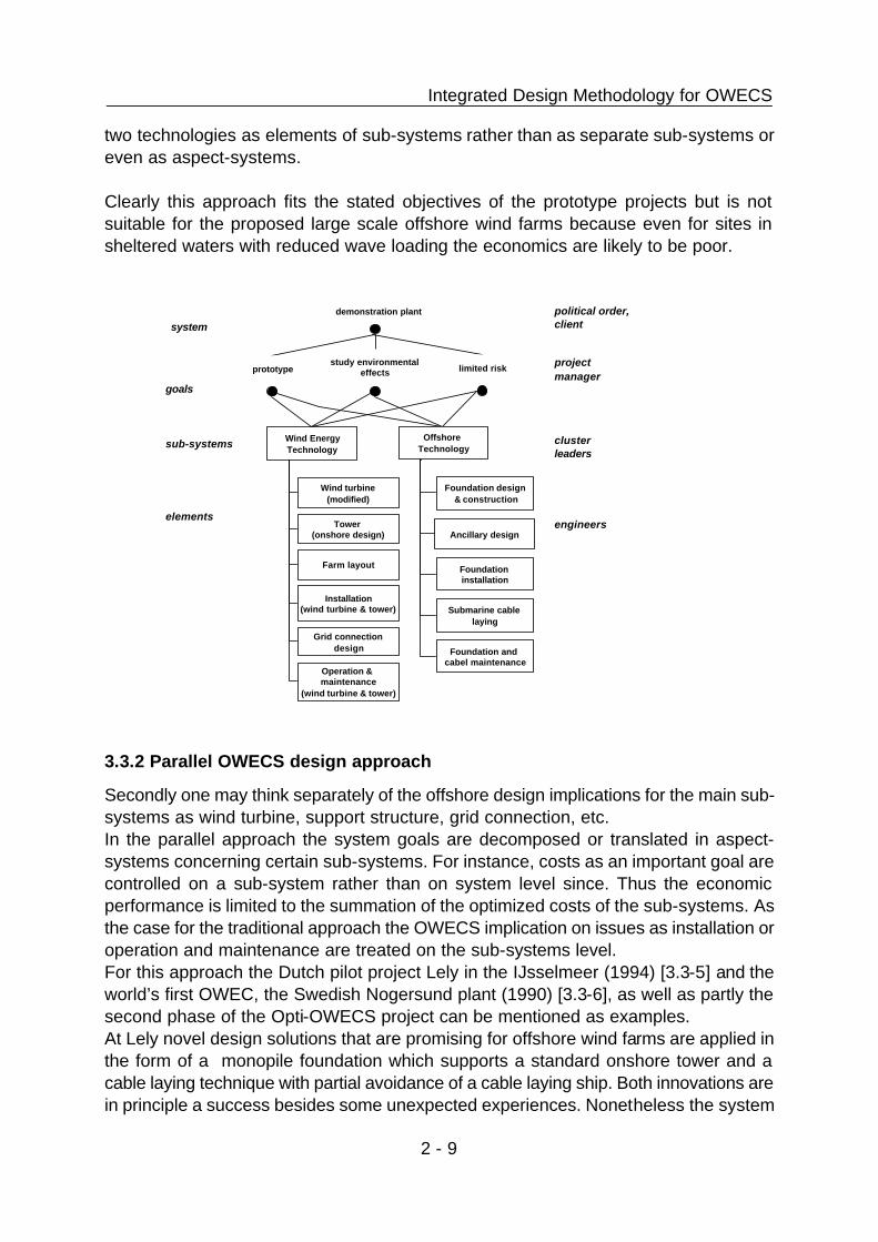
3.3.1 Robust or traditional OWECS design approach
The second Danish offshore wind farm at Tunø Knob (1995) [3.3-2,3] is a good example of a so-called ‘robust or traditional design approach’. To a lesser extent this is also true for the earlier farm at Vindeby (1991) [3.3-4]. In both cases the attribute ‘traditional’ refers to an onshore design approach applied to the offshore situation. Main objectives of both projects were the demonstration, the investigation of environmental effects and the gathering of first experience rather than high economic performance. Therefore more or less standard onshore wind turbines are applied. Wind turbines and towers out of the series production are installed in a quite similar manner as onshore (i.e. separate lifting of tower, nacelle, rotor) on a specially designed, stiff caisson which acts as a small artificial island. Furthermore, reduction of operation and maintenance costs is aimed for by well-proven onshore wind turbine designs marinised by features as for instance improved corrosion protection, air-tight nacelle, built-in lifting facilities, etc. The design process (figure 3.3-2) is organized in two main clusters according to the parent technologies i.e. wind turbine or wind farm engineering (comprising wind turbine, tower and farm layout, grid connection design) and offshore technology (comprising foundation and submarine cables). Note important aspects affecting the overall performance as installation or operation and maintenance are treated separately by the
system
sub-systems cluster leaders
project manager
engineers
(order,) client
elements
goals / aspect systems
design program
improved composite constructive diagram
diagram of concepts
requirements
coordination
conceptual solution
=
+
structure organisat ion members
Integrated Design Methodology for OWECS
2 - 9
two technologies as elements of sub-systems rather than as separate sub-systems or even as aspect-systems. Clearly this approach fits the stated objectives of the prototype projects but is not suitable for the proposed large scale offshore wind farms because even for sites in sheltered waters with reduced wave loading the economics are likely to be poor.
3.3.2 Parallel OWECS design approach
Secondly one may think separately of the offshore design implications for the main sub-systems as wind turbine, support structure, grid connection, etc. In the parallel approach the system goals are decomposed or translated in aspect-systems concerning certain sub-systems. For instance, costs as an important goal are controlled on a sub-system rather than on system level since. Thus the economic performance is limited to the summation of the optimized costs of the sub-systems. As the case for the traditional approach the OWECS implication on issues as installation or operation and maintenance are treated on the sub-systems level. For this approach the Dutch pilot project Lely in the IJsselmeer (1994) [3.3-5] and the world’s first OWEC, the Swedish Nogersund plant (1990) [3.3-6], as well as partly the second phase of the Opti-OWECS project can be mentioned as examples. At Lely novel design solutions that are promising for offshore wind farms are applied in the form of a monopile foundation which supports a standard onshore tower and a cable laying technique with partial avoidance of a cable laying ship. Both innovations are in principle a success besides some unexpected experiences. Nonetheless the system
Wind Energy Technology
Offshore Technology
Tower (onshore design) Ancillary design
Farm layout
Wind turbine (modified)
Grid connection design
Installation (wind turbine & tower)
Foundation design & construction
system
sub-systems
study environmental effectsprototype
demonstration plant
limited risk
cluster leaders
project manager
engineers
political order, client
elements
goals
Foundation installation
Foundation and cabel maintenance
Operation & maintenance
(wind turbine & tower)
Submarine cable laying

JOR3-CT95-0087 Opti-OWECS
2 - 10
aspects have not been fully considered, for instance in the investigation of the overall dynamics [3.3-7]. Again, this could be accepted because of the sheltered site and the demonstration character of the project. At Nogersund the support structure design, intended as a small scale prototype for a 3 megawatt OWEC, and the installation procedure are adapted from onshore procedures to offshore siting. The entire unit has been fully assembled and commissioned prior to towing to the final destination so that in-situ work was minimized. Within Task ‘Structural optimisation of sub-systems concepts’ of the conceptual design phase of the Opti-OWECS project this approach has been selected in order to build up expertise with the design of an OWECS and because certain advanced design methods are developed simultaneously within the other tasks i.e. economic analysis, development of design methods. This approach might be typical for demonstration or (near) commercial plants and is regarded as promising if strong experience is available at sub-system level. For instance, the application of offshore technology rather than civil or coastal engineering expertise is recommended. Moreover, management and resources are required for the communication between the design clusters and the project leader. A number of iterations in the design process might further be needed to achieve good matching of sub-system solutions and fulfilment of the system goals. Note that in the traditional as well as in the parallel design approach the OWECS is certified with respect to a wind turbine standard (whether valid for onshore or offshore) as well as a standard for offshore structures. Especially in the first approach this leads
Wind turbine Support structure Grid connection and farm layout
Ancillary design(Wind turbine installation)
Wind turbine (modified)
Operation & maintenance
(wind turbine, farm)
Installation (support structure
or OWEC)
Cable
Switch gear, transformer, etc.
Foundation & tower
Cable laying
system
sub-systems
energy yieldcosts of energy
demonstration or (near) commercial plant
lifetime
cluster leaders
project manager
engineers
order
elements
goals
costs installationstrength / stiffness costs reliabilitycosts
marinisationO & M
client
aspect-systems
Farm layout Support structure
maintenanceGrid connection
maintenance

Integrated Design Methodology for OWECS
2 - 11
to a high degree of conservatism. 3.4. Innovation by the integrated OWECS design approach 3.4.1 General principle
A considerable step further than the state-of-the-art, as described by the two already mentioned methods, is the so-called integrated OWECS design approach which tries to consider all of the particular properties of an OWECS (sec 3.1). Still, sub-system design is done in parallel based on the state-of-the-art in wind engineering and offshore technology. However, the solution is governed by overall criteria / aspect-systems such as: global economics, actual site conditions, entire system dynamics, structural reliability considerations, transportation / installation as well as operation and maintenance strategies. The design standards used are adapted to OWECS application and certification is done with respect to the particular site conditions.5 Therefore at least the site selection and a final check of the different stages of the design process (e.g. feasibility study, conceptual and final design) have to be done with respect to these global criteria. More demanding but of higher efficiency and quality is the integral consideration of the aspect systems during the design steps. The engineers in the different disciplines involved need assistance and (new) tools for judging intermediate results during the design process. This involves particular instruments e.g. overall cost model, O&M simulation tool, codes for design calculation of the entire OWEC, etc. as they are developed or extended in parallel to the conceptual design during the Opti-OWECS project (appendix B). The approach particularly applies to large-scale OWECS acting as elements in an (inter-)national energy system. Therefore in figure 3.4-1 the system objective or political order of ‘delivery of a considerable amount of substantial electricity’ is resolved in more controllable goals which typically are defined by the client e.g. a power company or investor. Note energy costs are only one (important) goal beside other as for instance power quality, quantity and persistence or lifetime. In order to achieve these requirements, aspect-systems related to the entire system are established for the goal and structural control.
5 The standards of the Germanische Lloyd [3.4-1, 2] for wind energy conversion systems and the IEC standard 1400-1 [3.4-3] provide identical design classes for onshore and offshore siting. Particular site conditions might be considered in a so-called Class S without predefined values for the environmental parameters.

JOR3-CT95-0087 Opti-OWECS
2 - 12
Note operation and maintenance is considered as a separate (structural) sub-system comprising elements of all other sub-systems. However, for convenience OWECS installation is treated as one item in the sub-system of support structure and installation. Moreover, operation and maintenance as well as installation are also established as
aspect-systems due to their particular importance. Two objectives of the Opti-OWECS project are related to this approach. Firstly, the integrated OWECS design approach is further developed and comprehensively described (chapters 4). Secondly, its first application is demonstrated in a design situation (chapter 5) [3.4-4]. In the following sub-sections the integrated OWECS design approach is evolved within four complementary variants each emphasising particular aspects of the OWECS properties e.g. economics, O&M aspects, overall dynamics and radical design solution. In practice features of all variants will be combined according to the particular requirements. 3.4.2 Economic optimisation within the integrated approach
The optimum economic performance of an OWECS can not be achieved by simple combination of individually optimised sub-systems. Moreover, a balance between capital cost, operation & maintenance costs and availability is essential. Several important design parameters influence different sub-systems / aspects and have often reversed influence on the costs of certain sub-systems.
Wind turbineSupport structure
and installationGrid connection and farm layout
Operation & maintenance (infrastructure & strategy)
Redesign wind turbine
Redesign rotor blades
Maintenance design
System reliabilityCable
Switch gear, transformer,
etc.
Support structure
Wind farm operation
system
sub-systems
power quality & quantity
( e.g. IEC, availability profile )costs of energy (e.g. < 5ECUct/kWh )
delivery of substantial electricity
lifetime ( e.g. 20 years )
economics adaptation on site installation &
commissioningdynamics &
structural reliabilityoperation & maintenance
cluster leaders
project manager
client
engineers
political order
aspect systems
elements
goals
OWECS installation
Wind farm layout

Integrated Design Methodology for OWECS
2 - 13
For instance an increased hub height results in higher energy gain but also higher support structure costs, OWEC installation costs and wind turbine maintenance costs. More exposed sites offer more wind energy but have to be payed by larger investments, higher O&M costs and potentially greater transmission losses if the distance from shore is larger. In an integrated design approach such relations are considered from the outset. Moreover, the efforts in the design work can be directed on crucial cost elements e.g. operation & maintenance costs. During the course of the design process the sophistication of the cost evaluation should increase from simple estimates of the cost-breakdown and levelised production costs (LPC) in the feasibility study, to an OWECS cost model (appendix B.1) during the conceptual design to a detailed evaluation in the final design phase. After each phase entire OWECS concepts/solutions developed for an particular site should be chosen by global considerations. The integration of structural and economic considerations is one base of the Opti-OWECS project and is therefore present in various parts of the study, particularly it has been demonstrated in the final design solution (sections 3.8 and 4.7, chapter 10 of [3.4-4]). 3.4.3 Design for RAMS within the integrated approach
Challenging design targets for RAMS (Reliability, Availability, Maintainability and Serviceability) of an optimised OWECS can only be met by an integrated design approach. Therefore this sub-section is devoted particularly to the relation between RAMS and the integrated OWECS design approach [3.4-5]. The targets with respect to the product delivered by the OWECS (i.e. the price, quantity, quality and persistence of the delivered electrical power) do not only guide the technical design but as well the design for reliability and availability (failure states and rates), and the design for maintainability and serviceability (rate, ease and costs of repair and regular service). Since there is only a limited possibility to use experience for the development of an integrated maintenance approach for OWECS, a knowledge based methodology must be applied. Likewise to the structural design, the following specific targets are set and effectively controlled in all phases of the design process.
· reliability target i.e. the probability that the OWECS is able to fulfil its functional design targets,
· availability target i.e. the fraction of time that the OWECS is able to operate as intended under given external conditions,
· maintainability target i.e. the probability that a malfunctioning OWECS can be brought back into operation within a given time,
· serviceability target i.e. the ease and costs at which regular (scheduled) service can be applied, specified the fraction of time and the costs needed for service.

JOR3-CT95-0087 Opti-OWECS
2 - 14
The principal relation and development of design targets and design specification during the different design phases is illustrated by figure 3.4-2. The specification of the functional design targets of the OWECS, its RAMS targets, and the design of the installation and maintenance concepts should first be addressed in an integrated way on the systems level during the feasibility study. Only then the optimal solution will be achieved in terms of e.g. the lowest value for the LPC. The targets on the systems level should then be translated in an consistent way to specifications on the sub-system level during the conceptual design. Next for the final design the specifications have to be determined also on component levels. Finally the sub-
components are treated analogous during the design specification phase. After the assessment of the local consequences of the specifications on a certain level of the system e.g. by a simplified calculation of reliability and availability, the results should be evaluated on the system level. Such a process of continuously evaluation and re-evaluations of the targets and specifications on all the design levels assures the most optimal design of the OWECS. With respect to the further assessment of the possibilities to achieve the RAMS targets it is worthwhile to apply design tools for reliability and availability calculations. Such design tools range from simple probabilistic techniques for simplified reliability and availability calculations based upon generic failure rates (small, inner iteration loops in figure 3.4-2), to more advanced Markov chain modelling. For complex systems such as an OWECS the most often applied technique for evaluation of the O&M process are Monte-Carlo simulations (large, outer iteration loops figure 3.4-2).
System specification
Conceptual design
Feasibility study
design specification OWECS level
RAMS targets OWECS level
simplified R&A calculation
design specification sub-system level
RAMS targets sub-system level
local R&A calculation
design specification component level
RAMS targets component level
local R&A calculation
design specification sub-component level
RAMS targets sub-component level
local R&A calculation
OWECS evaluation with
RAMS design tools
Final design
system level
sub-component level
component level
sub-system level

Integrated Design Methodology for OWECS
2 - 15
Of course it is evident that design solutions of the OWEC unit design level will have consequences on the design of the OWECS maintenance concept and vice versa. But also an integrated approach of i.e. the design of the installation process and the maintenance process will be beneficial for achieving the most optimal solution. An example is the possibility to use (general purpose or purpose build/modified installation infrastructure, such as platforms, cranes, boats etc afterwards as maintenance infrastructure, which may yield a more economic approach than considering the installation process and the maintenance concept independently. Within the development the Opti-OWECS design solution RAMS aspects have played an important role in the marinisation of the wind turbine and the choice of the maintenance hardware and O&M strategy (sections 3.6 and 4.5, chapter 8 of [3.4-4]). Nonetheless, a consistent application of the described design for RAMS was beyond the scope and is a worthwhile study of its own. 3.4.4 Overall OWEC dynamics within the integrated approach
System dynamics and dynamic interactions between sub-systems e.g. wind turbine and support structure or OWEC units, grid connection and public grid have a high importance for OWECS and should be considered in an integrated way during the different design phases. Here some examples related to OWEC dynamics are mentioned.
Feasibility study · (qualitative) compatibility of support structure and wind turbine concepts e.g. support structure stiffness, aerodynamic damping, fatigue due to wind turbine loads, · (qualitative) compatibility of support structure concepts and site specific loading
e.g. sensitivity to hydrodynamic fatigue, loads due to breaking waves or breaking ice
Conceptual design · sensitivity analysis of dynamics with respect to soil properties, · assessment of ratio between aerodynamic and hydrodynamic loading (extreme as
well as fatigue), · parameter studies on dynamic loading in frequency (or time) domain, · simultaneous optimisation of wind turbine concepts (e.g. rotor speed, blade and
drive train layout and rotor diameter) and support structure concepts (e.g. stiffness, approximate hub height),
Final design · detailed dynamic analysis of OWEC with design tools in the time domain (especially
if fatigue is governing),

JOR3-CT95-0087 Opti-OWECS
2 - 16
· fine tuning of dynamics, · investigation of effects due to the variability site parameters within the wind farm
The integration of dynamic considerations in the design process is demonstrated by the Opti-OWECS design solution (sections 3.7, 4.6, chapter 9 of [3.4-4]). 3.4.5 Radical design within the integrated approach
The use of unconventional designs for entire sub-systems might provide a major benefit for the entire OWECS under the condition that such radical design is governed entirely by the offshore requirements rather than by adapting onshore experience for the offshore situation. For instance the wind turbine would be designed consistent for offshore application rather ‘marinising’ an onshore design. Without an assessment of the feasibility and the pro and cons some further examples are listed here for illustration. In the wind turbine sub-system one may think of the ‘ultimate wind turbine’ i.e. an extremely flexible turbine with the absolute minimum of components [3.4-6], umbrella type wind turbines which adjust their shape according to the wind loading [3.4-7] or no-maintenance concepts. Unconventional support structures are proposed by the multi turbine concept [3.4-8] and the Multi Unit Floating Offshore
Wind Farm (MUFOW) concept (fig 3.4-3) [3.4-9]. Ultimately such a radical approach might be the most promising. However, unproven or just ‘big’ designs, do not lend themselves well for application in the demanding offshore environment. The experience gained during the course of the other approaches mentioned previously is necessary. Therefore, the radical approach is not considered

Integrated Design Methodology for OWECS
2 - 17
feasible at the moment but may be required for very large offshore wind farms with a capacity in the GigaWatt range [3.4-10].


Integrated Design Methodology for OWECS
2 - 1
4. Integrated OWECS design approach During the course of the Opti-OWECS project the integrated OWECS design approach (section 3.4) has been further developed. This chapter presents a comprehensive description of the steps involved in this methodology and tries to address the main issues in the involved disciplines. As a matter of fact, most remarks on the different areas are of fairly general nature and may be regarded as evident for any expert of that specific subject. However, the additional value of the documentation is seen in the overview on the various aspects and in the interrelations between them. Further explanations and first experience on its application are provided in chapter 5 by means of an example, i.e. the OWECS design solution developed during the course of the project. 4.1. Organisation of design process and design requirements The success of a design process is largely dominated by the organisation of the design team as the process and organisation can hardly be separated. In section 3.4.1 (figure 3.4-1) an organisation scheme for the goal and structural control of integrated OWECS design approach has been proposed. In this structure the management is done by a ‘team of cluster leaders’ in which every partner is represented and all major decisions which affect the design of the system are taken by the team. Each person in this group manages a design team which is responsible for the development of a particular sub-system. It should be tried to reduce the number of relations between the various sub-systems by suitable selection of the sub-systems. This will reduce potential design conflicts and will increase the flexibility of a design team 6. Decisions made by the “head design team” should be carefully and consequently be reported as they serve as “requirements” for the sub-system designs of all teams involved. As illustrated in figure 3.4-1 the subsystem design is controlled with respect to the project goals by means of five aspect systems i.e. economics, adaptation on site, dynamics & structural reliability, installation & commissioning, operation & maintenance. This will only be effective if the aspect systems are broken down into qualified and controllable criteria and if tools/procedures are available to measure the design to these requirements (see section 4.5.2, step 2.1b) of the approach) . In the figure the complex system is split-up into sub-systems each setting its design requirements. These requirements are then input for each design team to provide a satisfying solution which synthesize the requirements. If there are problems in the
6Note that this proposed organisation is very similar to the co-operation between the partners of the Opti-OWECS project.

JOR3-CT95-0087 Opti-OWECS
2 - 2
generation of such a solution the requirements should be re-evaluated by the “head design team” as the changes will influence all sub-system designs (but probably not to the same extent). 4.2. Design process in a nutshell 4.2.1 Entire design life cycle and the elementary design cycle
In this report the integrated design approach for OWECS is developed with respect to some basic principles of the modern design methodology in civil engineering [4.2-1]. Prior to the consideration of the particular features of OWECS some explanations are given of the entire design life cycle and the elementary design cycle which might be applied in the different steps of the design process. In the life cycle of the design process several activities can be identified. Ideally, as a result of the activities a solution for the given problem is obtained. During the process the vague description of the problem evolves into a detailed description of the design. This evolving description can be regarded as “requirements” for every new activity (step). Figure 4.2-1 gives the relation between the activities and requirements in the design process as a function of time. The following requirements can be identified in time:
· Problem statement As a result of the initial project identification (step 0) the problem statement defines the objectives of the design (e.g. delivery of a certain amount of electricity from offshore wind energy at a certain location and over a certain time span), the acceptable price (e.g. investment costs, costs of energy) and the demanded quality (e.g. power variation, grid influence, etc.). By this the design problem is stated.
· Overall realization plan Based upon the characterization of the design problem a feasibility study (step 1) is carried out which obtains a functional description of a solution. The requirements are refined with respect to criteria as function, technology, construction and economics.
· Preliminary or conceptual design The overall realization plan forms the input to the conceptual design (step 2). The definition of main dimensions and site result in the preliminary design and the final requirements on function, technology, construction and economics.
· Final design

Integrated Design Methodology for OWECS
2 - 3
Next materials are chosen, dimensions are fixed, structure i.e. relations between sub-systems is generated and the final design is documented as result of the structural design (step 3).
· System Specifications In the last step of the design process (step 4) detailed engineering or elaboration of the final design in the design reports, specifications and drawings for the implementation (i.e. construction, installation and commissioning) and (post-) exploitation are obtained. Further the use of resources and the data flow is planned.
Start of design process
Step 1: Feasibility study
Objectives Problem statement
System Specifications
Preliminary Design Concept
Function Overall realization plan
End of design process
Step 0: Project identification
Step 4: Elaboration / Specification
Step 3: Structural design
Step 2: Conceptual design
Final Design
Start: Problem
Analysis
Value of concepts
Concept solutions
Criteria
End: Acceptable solution
Evaluation
Simulation
Synthesize
Expected performance
Decision

JOR3-CT95-0087 Opti-OWECS
2 - 4
Within the different steps of the design process more or less explicit the elementary design cycle in civil engineering can be followed (Figure 4.2-2). Initially the problem is analysed with respect to the desired function of the solution and the required process to come to this solution. By this the criteria are defined which the solution (i.e. the ‘building’) and solution process (i.e. the implementation) have to fulfil. These requirements are stated as demands on functional and technological effectiveness and constructive and economic efficiency. Next the creativity of the designer is demanded in producing several concepts or alternatives in parallel. Here often several iterations of creation, improvement and discarding are required. The expected performance of the different concepts is simulated by calculations, visualization or (intuitional) judgement. Likewise to the common rule of brainstorming it is advantageous to separate this executive step from the previous creative phase. In the following the most promising options are evaluated with respect to the initially stated criteria and a ranking is generated which is used for the final decision on an acceptable solution. In case the remaining concepts are not convincing either new concepts have to be developed (inner right loop) or the problem analysis is repeated (outer right loop) which results in an adjustment of the criteria. For an efficient design process it is essential to apply the elementary cycle extensively but only within the different steps of the entire design rather than for the design process itself. Otherwise it will hardly be possible to stay within the project resources and time schedule. 4.2.2 Steps in the integrated OWECS design approach
In the rest of this chapter the integrated design methodology is described mainly from a scientific point of view. Firstly, emphasis is given to the sequence and interaction of the different parts of the work contents rather than to organisation, scheduling and resource management. Secondly, only the relation between the technical steps is considered here, no interaction with the ‘customer’ or the ‘public’ are taken into account. Experience has shown that such non-technical issues e.g. public acceptance, aesthetics, etc. can have a significant and sometimes unexpected impact on design processes. Typically such evaluations together with external parties should be taken place after one and prior to another step. For instance one approach to public opinion, applied recently very successful in the planning of (onshore) wind farms, is to work very openly and to bring as much information as possible to the public at a very early stage. Ultimately this implies to tell the people about the project even before the full design and layout is known to the project team. The advantage by this approach is that the people feel that they have the possibility of including changes in the project before it is too late. Further, one can promote the own plans to the public and correct misunderstandings.

Integrated Design Methodology for OWECS
2 - 5
Another approach followed during the Dutch feasibility study for a 100 MW offshore wind farm, the so-called ‘Nearshore project’, is to give an environmental organisations an active role in the site selection procedure [4.2-2].

JOR3-CT95-0087 Opti-OWECS
2 - 6
Start of design process
Step 1.1 a): Pre-selection of initial sites
Objectives Problem statement
System Specifications
Preliminary Design Concept description
Function Overall realization plan
End of design process
Step 0: Project identification
Step 4: Elaboration / Specification
Step 3: Structural design
Final Design
Step 1.2: Evaluation of OWECS concepts
and sites
Step 1.1 b): Pre-selection of initial sub-system concepts
Step 1.3: Selection of (=>2) concepts
and (>2) sites
Support structure, installation
Operation & maintenance
Wind turbine
Step 2.1 a): Conceptual sub-system design for all OWECS concepts and sites
Step 2.3: Selection of final concept
and site
Step 2.2: Evaluation of concepts and sites
Step 2: Conceptual design
Step 1: Feasibility study
Grid connection, farm layout
Step 2.1 b): Development of OWECS
evaluation tools

Integrated Design Methodology for OWECS
2 - 7

JOR3-CT95-0087 Opti-OWECS
2 - 8
In this section 4.2.2 the integrated design approach is described in a nutshell (figure 4.2-3) whilst in the sections 4.3 to 4.7) each step is successively elaborated. The process starts with the project identification (step 0, section 4.3) and the statement of the project objectives. Next in the first step (section 4.4) a feasibility study is performed which results in a selection of a number of concepts related to certain sites (step 1.3) and the overall realization plan. The choices are based on the separate pre-selection of sites and sub-system concepts (step 1.1) and the evaluation of the combination of sites and OWECS concepts (step 1.2). In the conceptual design (step 2, section 4.5) the chosen combination of sites and OWECS concepts are further developed on a sub-system level (step 2.1a). In parallel tools for the evaluation of the OWECS performance and the control of the aspect systems are developed or updated (step 2.1b) Again an evaluation (step 2.2) and selection of the final concept at the final site (step 2.3) takes place. Once the outcome of this phase is given the client does not have opportunities to change concepts or scope of work without incurring substantial delay and extra costs [4.2-1]. Therefore the outer right loop from the conceptual design to the problem identification is indicated only as a dashed line. In the structural design in step 3 (section 4.6) the ‘dimensions’ of the design are fixed and the relation between the sub-systems is generated. System specifications are worked out in the final, fourth step (section 4.7). In the following sections emphasis is put on the problem identification, the feasibility study and the structural design since here the aspect of integrated design is most obvious and important; moreover, here the base for the success of the project is founded. Appendix C presents a check list with attention points for an OWECS designer which might be used as a reference. 4.3. Step 0: Project identification The entire design process starts with the project identification and the statement of the project objectives. Often the client (a utility, a private or public organisation) will define some pre-conditions or demands that have to be considered in the definition of the

Integrated Design Methodology for OWECS
2 - 9
project objectives. One of the most important objectives is the operational goal of the OWECS e.g. demonstration or commercial plant, lowest energy costs, certain minimum amount of power, limitations of short term and long term power variations, etc. since this will have a large impact on the optimum design. After client’s approval the objectives should be documented as a reference document for the further development.
Start
Technological condit ions • state of technology (e.g. proven, state-of-the-art or innovative ) • design approach (e.g. integrated OWECS design approach ) • design standard • approx. size of OWECS and OWEC units • design lifetime
Objectives Project identif ication
End
Pre-conditions (if any), Cl ient 's demand
Definit ion of OWECS objectives • demonstration or commercial plant, • social and political conditions, • identification of 'operator' and 'customer', • operational goal (e.g. lowest energy costs, base level power, l imited power variations, etc. )
Socio-economic condit ions • economic parameters, green taxes, subsidies, • power purchase conditions, • public acceptance, • (inter-)national legal constraints, • environmental constraints
Geographical and site condit ions • territory to be considered for wind farm • territory for power delivery • a priori site conditions (if any) (e.g. range of water depth, distance from shore )
Evaluation w.r.t . c l ient 's demands
Evaluation w.r.t . c l ient 's demands

JOR3-CT95-0087 Opti-OWECS
2 - 10
Next some main project constraints as the order of magnitude of the project resources and the available time span should be identified. Moreover, a check on a possible lack of experience inside the team7 is worthwhile prior to the start of further investigations. In the following a list on the conditions related to various aspects should be compiled. For instance, one may consider the three areas of socio-economic conditions, technological conditions and geographical site conditions, respectively (Figure 4.3-1). Again these requirements should be evaluated with respect to the client’s demands and finally be documented in a reference document which should carefully be updated in order to become more specific during the course of the project. 4.4. Step 1: Pre-selection of initial sites and design concepts 4.4.1 Step 1.1 a) Pre-selection of initial sites
The starting point for the pre-selection of initial sites are the objectives and the project identification from step 0. It is envisaged that here one or more territories are mentioned (e.g. Dutch North Sea, southern Belgium coast, etc. ). The next step is to identify site criteria. These criteria can be split into restrictions, favoured site parameters and required area. The restrictions directly exclude areas within the territory which are prohibited to locate OWECS due to other users (e.g. military, recreation, conservation, traffic, exploitation of resources, etc. ), other offshore installations (e.g. platforms, pipelines, etc.) or legal aspects. Examples of site parameters are e.g. minimum mean wind speed, minimum / maximum water depth, minimum / maximum distance to shore / infrastructure, maximum seabed slope, minimum soil bearing capacity, etc. The final criteria, available area, should reveal if it is possible to locate an OWECS of a certain installed power via rules-of-thumb (e.g. 0.08 - 0.3 km2/MW). Gathering of consistent information for the different territories or even within one territory will be a major and time consuming task which probably can only be managed if estimations, extrapolations and manual corrections are applied on the rough data. [4.4-1]. Successive evaluation of the territories with respect to the criteria reveal a number of ‘sites’ within the territory which are interesting to locate OWECS (e.g. the NL-1, NL-2,
7 In such an early stage the project team will probably comprise only very few people and organisations. Thus, adequate know-how is essential especially now in order to avoid an incomplete or weak statement of the objectives and conditions.

Integrated Design Methodology for OWECS
2 - 11
…, NL-7 sites in the Opti-OWECS study). For each site in each territory the performance is estimated by looking at the expected energy yield, required capital costs, risk, etc. By comparing the preliminary performances of all the sites several ‘potential sites’ are selected. Due to neglecting the relation between sites and concepts and the simplicity of the evaluation based upon engineering intuition and ‘back-of-the-envelope’ type calculations the selection should not be too strict and several sites should remain for further investigation. Even one may state that the sites should be distinctly different in order to learn more about the pro and cons of the different concepts and the influence of the site parameters.

JOR3-CT95-0087 Opti-OWECS
2 - 12
O b j e c t i v e s Pro jec t ident i f ica t ion
Ident i f icat ion of s i te cr i ter ia - res t r ic t ions ,
- f a v o u r e d s i t e p a r a m e t e r s , - r e q u i r e d a r e a
Evaluate ter r i tory w. r . t . c r i te r ia
O b t a i n i n f o r m a t i o n
Eva lua t ion o f te r r i to r ies : j = 1 . . m
Ident i f ica t ion of m terr i tor ies
Cr i te r ia fo r p romis ing s i tes
D e c i s i o n o n f u r t h e r cons idera t ion o f s i te i
E s t i m a t e p e r f o r m a n c e o f s i t e i
Eva lua t ion o f s i tes : i = 1 . . n
I den t i f i ca t ion o f n s i tes w i th in te r i tory j
Parameters o f in i t i a l s i tes ( e .g . mean w ind speed , d is tance to
shore / in f rast ructure , range of wa te r dep ths , wave and ice c l imate ,
max . seabed s lope )
S t a r t
E n d

Integrated Design Methodology for OWECS
2 - 13
4.4.2 Step 1.1 b) Initial selection of sub-system concepts
In parallel to the initial selection of sites in step 1.1 a) a number of sub-systems concepts are chosen. First ‘many’ of the generic options for the different sub-systems (e.g. support structure options: single or multi unit, piled or gravity based, lifted or floated installation, monotower or braced/lattice tower) are compared qualitatively on a sub-system level. Relation to the territories/sites and the other sub-systems are only considered globally. For instance, the lattice tower option is ruled out if only ice loaded sites are considered. For each sub-system at least two to three options should remain for which the gross data and particular features are compiled and documented in order to facilitate the comparison on system and site level in step 1.2 4.4.3 Step 1.2: Evaluation of OWECS concepts at sites
The evaluation of concepts begins with a broad qualitative examination of the advantages and disadvantages of the identified concepts, focusing on how well the sub-system concepts of step 1.1b) can be coupled - e.g. how well do the preferred wind turbine concepts fit with the preferred support structure concepts. Despite being only qualitative, this may involve a considerable amount of work. This time, however, will be well spent as it will avoid effort being wasted in the detailed evaluation of flawed concept combinations. Part of this work should also identify areas in which the consortium has insufficient knowledge to make decisions, and attempt to rectify the situation through the collection of information. At the end of this stage, everyone involved should have a good understanding of the broad advantages and disadvantages of the concepts. Next, a first step should be made at coupling the results of the pre-selection of sites (step 1.1a) with the pre-selection of concepts (step 1.1b). These two tasks will, most likely, have been undertaken by different groups/individuals without a full appreciation of the implications of their decisions. It is thus important that which concepts are most suitable for which sites is established at an early stage. The nature of the available sites will have an important influence on the design of the concepts, and, therefore, the economic and technical viability of each site/design concept combination. Some weight should be given to any social or political obstacles (e.g. protests from conservationists) or encouragement (e.g. government grants) that might be encountered with the decisions to develop particular sites in a particular manner. Assuming, as is likely, that economics is an important factor in the design of the OWECS, the next stage is to carry out a short ‘back of the envelope’ style economic evaluation of the concepts and sites. This should allow the rapid elimination of any severely un-economic concepts, and ensure that economically promising options are not eliminated simply because they present substantial technical or political challenges.

JOR3-CT95-0087 Opti-OWECS
2 - 14
4.4.4 Step 1.3: Selection of OWECS concepts at sites
In the light of the information produced by the above, a decision should be made as to which concepts, sites and combinations warrant more detailed development during the conceptual design in step 2. 4.5. Step 2: Conceptual design 4.5.1 Step 2.1 a): Conceptual design of sub-systems
The conceptual design of the sub-systems is done in parallel under consideration of major interactions in a simplified manner8. Also the relation between the site conditions and the design is taken (although simplified) into account. The procedures followed within the different components is similar to those described in much more detail in section 4.6 on the structural design. However, now the emphasis lays on generating the functional relations and the overall dimensions rather than in designing all components and solving detail problems.
8 For instance, the loads transmitted from the wind turbine to the support structure are also depending on the support structure properties (e.g. eigenfrequencies). Here it is assumed that a certain set of equivalent fatigue loads at the tower top is valid for a range of support structure concepts.
Start
Comparison of 'many' sub-systems concepts
Wind turbine • power range, • basic concepts (e.g. rotor, control, speed, transmission, etc. ), • existing base case designs, • qualitative reliability
Description of initial sub-system concepts
End
Objectives and project identification
Farm layout • approx. farm capacity, • approx. number of OWEC units
Grid connection • power transmission type (AC or DC) • cable or overhead line • onshore voltage level
Support structure (bottom-mounted) • single or multi unit, • piled or gravity based, • lifted or floated installation, • monotower or braced/lattice tower
Operation & Maintenance • O&M approaches • O&M hardware • O&M strategies
Selection of 'several' initial sub-systems concepts (based on (sub-)system considerations, engineering intuition,
experience, literature, etc.)
Compilation of gross data (preparation of concept and site evaluation )
Evaluation of sub-system concepts

Integrated Design Methodology for OWECS
2 - 15
4.5.2 Step 2.1 b): Development of OWECS evaluation tools
For the evaluation of the OWECS performance on a system level e.g. overall economics, structural reliability consideration, overall dynamics, operation & maintenance behaviour, etc. particular tools are required which are (often) not available by the parties concerned with the sub-system development. Within the Opti-OWECS project such tools (i.e. OWECS cost model, OWEC design tool, O&M simulation tool) have been developed or extended [4.5-1]. Even if these particular tools would be used in another project adjustment of the models implemented, update of the considered reference data and conditions, etc. will be required due to the complexity of an OWECS (There would not be two identical OWECS.). Thus the step of the development of such tools is considered also to be a part of the integrated design methodology, in general. The objective of this task is twofold, preparation of the evaluation of the OWECS concepts in relation to the selected sites (step 2.2) as well as assistance during the conceptual development (step 2.1 a) ) which will be most effective if some intermediate evaluations are done. Moreover, one may think of investigation of certain issues as for instance determination of the promising ranges for the hub height, support structure stiffness, etc. 4.5.3 Step 2.2: Evaluation of OWECS concepts and sites
It is essential that the evaluation procedures are closely coupled with the preliminary design work. It is unlikely that the options can be adequately compared without some steps being taken toward developing a design, as, without some design effort, the important features of the concepts will not be revealed. If performed properly, the concept evaluation should have a significant impact on the design work, as indeed should the design work on the evaluation. 4.5.4 Step 2.3: Selection of OWECS concepts and sites
Once the preliminary designs are relatively fixed, the design tools can be completed or ‘tuned’ and any other necessary information has been collected, a final decision can be made as to which option or options can be taken forward to the detailed design stages. The final decision process is likely to highlight some minor factors which have been overlooked, and thus some allowance must be made in the planning for last minute changes in the preliminary specifications and consequent re-evaluation. For the selection the application of a cost model (valid for the considered concepts) developed within step 2.1b) (previous section) can be very valuable. For instance different sites with distinct wind conditions and site parameters can be compared.

JOR3-CT95-0087 Opti-OWECS
2 - 16
Moreover the effect of changes of design and site parameters for a certain OWECS can be estimated. The process finishes with the specification of one preliminary design9 to be investigated in detail in step 3. 4.6. Step 3: Structural design 4.6.1 Structural design of sub-systems and interaction between them
The structural design phase yields the solution for the problem of the client based on the concept and the site chosen at the end of the conceptual design phase (step 2). Again the design work of the sub-systems is done in parallel. However, now the interactions between the subsystems are taken into account as complete as possible (Figure 4.6-1). For instance, between wind turbine and support structure design a number of iterations might be necessary until the design solution has converged. In the next subsections one possible approach for the design of each sub-system is comprehensively described. By this, support structure and installation procedure are treated as one sub-system whilst grid connection and farm layout are treated
separately.
9 It is likely that the structural design will be done only for one particular concept at one site.
Wind turbine
Farm layout
Grid connection
Support structure
Operation & Maintenance
Installation procedure
Interactions and global criteria
• performance of OWECS (e.g. cost of energy, investment, energy yield, power variation, etc.)
• dynamics of integrated system
• structural reliability considerations
• operational behaviour
• installation and commissioning
• time scheduling
OWECS sub-systems
major interaction minor interaction

Integrated Design Methodology for OWECS
2 - 17
4.6.2 Wind turbine design for offshore siting
In the design of the wind turbine for the offshore siting two fundamental approaches exists: Firstly, the so-called ‘marinisation approach’ i.e. the adaptation of a more or less existing (onshore) wind turbine design for the offshore situation. This way is followed by all existing offshore wind farms so far and will also likely be followed in the near future. Secondly, the ‘design for RAMS (Reliability Availability Maintainability Safety) approach’ which considers the RAMS requirements of the wind turbine, as crucial part of the system OWECS, as governing criterium for the design. For instance improvement of wind turbine reliability and availability may overrule (aerodynamic) efficiency considerations. The RAMS approach has not be followed so far but it might be required if the full potential of a large-scale exploitation of offshore wind energy should be used. • Marinisation approach This approach is directly based on the experience build up in the wind turbine industry over the last two decades and comprises the consideration of the offshore requirements in six common design steps i.e. establish design requirements, overall concept selection, aerodynamic design, design of the load carrying structure, design of assisting components (including reliability, maintainability and installation aspects) and economic and technical evaluation. Offshore considerations take place at various points. The design requirements on e.g. efficiency, availability, power quality, economics, safety, etc. are defined by the OWECS objectives (step 0) or directly by the client. Furthermore the concept solution might be taken with respect to robustness and reliability e.g. favouring more simple, passive controlled designs. Also the choice between a two- and three bladed rotor might have offshore a different result than onshore. The aerodynamic design may be adopted to the harder wind regime, lower turbulence and wind shear as well as relaxed noise limitations. Typically this will yield in higher tip speed and more slender blades. Next the design of the load carrying structure has to take into account the different wind regime, the (probably lower) dynamic stiffness of the support structure and generally the differences between onshore and offshore design standards. As far as it is known today it can be assumed that the hydrodynamic excitation of the support structure does not have a considerable effect on the wind turbine itself [4.6-1, 2]. Next, in the design of the assisting components especially the corrosion protection and the reliability of the control & safety system, sensors, etc. and enhanced safety and remote control are particular consideration.

JOR3-CT95-0087 Opti-OWECS
2 - 18
Start
Quantitative calculation of energy yield and noise
Qualitative calculation of rotor loading
Design of assisting components (e.g. control & safety system, housing, etc.)
Maintainability improvement (PM intervals, PM efforts, CM effort,
modularity, permanent / temporary aids)
Wind turbine design
End
Installation design (e.g. modularity, lifting requirements,
commissioning at factory, etc.)
Establish overall configuration (largely defined by reference wind turbine (if any) ) control type: pitch, stall, assisted stall speed concept: fixed, limited or full variable drive train concept: geared, direct drive hub concept: fixed, teetered rotor concept: blade number, speed, diameter, power yaw system: rigid, flexible, free electrical system: generator concept safety system: brakes, etc.
Establish aerodynamic rotor design
Reliability, maintainability,
installation adequate ?
Economic and technical evaluation
Intermediate OWECS concept(s)
and site(s) from step 2
Aerodynamic re-design adequate ?
Evaluation of aerodynamic and operational loads
with dynamic simulations of wind turbine and tower
(fatigue, extreme events)
Establish design of load carrying structure
Structural re-design adequate ?
Establish behaviour of control system and electrical system
Reliability improvement of components
(by over-specification, redundancy, protection, capsulation, condition
monitoring, etc.)
Establish design requirements e.g. efficiency, availability,
power quality, economics, etc. derived from OWECS objectives

Integrated Design Methodology for OWECS
2 - 19
The aggressive sea climate is tackled by capsulation, heating and/or internal overpressure of the nacelle, increased insulation of electrical equipment (can be necessary even for a closed nacelle). Reliability improvements of components are achieved by over-specification, redundancy, corrosion protection, condition monitoring, de-icing of wind sensors, battery backup, passive redundant parking brake equipment, redundant feeding of local power, etc. Safety and remote control features are increased by automatic fire protection system, radio link for communication (alternatively optical fibre connection inside the power cables), control system changes, etc. Further, the maintainability will be enhanced though lengthening of preventive maintenance intervals e.g. self-lubricating bearings and reduction of efforts for preventive (PM) and corrective maintenance (CM) due to modularity and permanent or temporary aids (e.g. cranage facilities). The installation design has to face that as less as possible work should be required offshore favouring commissioning in the harbour or at least throughout testing at the factory. Moreover lifting requirements of offshore cranes have to be considered. Finally a throughout economic and technical evaluation of the design is carried out which has to incorporate important OWECS aspects. Due to the complexity of the wind turbine system the design process requires even for large wind turbine manufacturers cooperation with sub-suppliers, manufacturers, certification authorities, etc. Important decisions should be taken in accordance with all of these parties and the client. Interactions between the design of the wind turbine and of the other sub-systems exists mainly between aerodynamic design and energy yield/economic performance, between aerodynamic as well as structural wind turbine design and support structure design [4.6-3], wind turbine generator and grid connection, wind turbine design and operation & maintenance design. • Design for RAMS approach An optimal design of a wind turbine for offshore application may require a radical change in the design philosophy followed for onshore application. It is evidently so that a marinisation scheme has to be followed in order to establish onshore failure rates in an offshore environment, but a design for RAMS starts in fact from the other direction. From the integral design approach for the OWECS targets for the wind turbine RAMS targets are derived. These targets, together with the other technical and economic targets determine the wind turbine hardware design. It may well be that such a combined approach leads to an offshore design which is so significantly different from an onshore wind turbine design, that the design will never be economic and may not

JOR3-CT95-0087 Opti-OWECS
2 - 20
even admitted for onshore location, e.g. because of excessive noise or because of inconsistency with onshore regulations regarding public safety. It is impossible to make firm statements about the lay out of a wind turbine designed according to the RAMS approach. A clear condition is however a significant reduction of the number and the endurance of visits to be paid to the OWEC for service and repair purposes compared to the state-of-the-art onshore designs. Taking this into account a number of promising design lines can be described in some more detail.10 One design philosophy may be to reduce the number of components to a minimum. This will reduce the number of possible failure modes and therefore lead to a more reliable turbine which is also easier to maintain and service. A two bladed fixed pitch direct drive wind turbine would be a good choice within such a philosophy. A second approach may be to adopt a modular design line. In such case the modules should be designed and located such that easy maintenance and service is assured. Furthermore the exchange of faulted modules must be possible in a quick and easy way, in order to keep downtime low, and thus keep the availability on the required level. A third possibility is a design line using integrated components provided these integrated components are easy to service. However their maintenance will probably be difficult and long lasting. Therefore such integrated component approach should make use of highly reliable components resulting in low failure rates. The fourth design line described here adopts an integral exchange philosophy. As soon as a failure is detected an integral part of the wind turbine, which may well be a complete nacelle including blades is replaced. Repair can then take place at a location with a (better) controlled environment and provided with all necessary repair equipment. A repaired nacelle may then be used as exchange unit for the next OWEC failure detected in the offshore wind farm. Such repair base can be located onshore as well as offshore. In the latter situation the repair base is most probably located aboard a (jack up) platform as a part of the OWECS infrastructure. No matter what design philosophy is followed the actual detailing of the design will require a marinisation scheme for all the components. As said before the number of scheduled (preventive) maintenance visits and repair visits should be reduced to a minimum. Application of SCADA monitoring equipment may support decisions regarding the service need of a specific machine or component. By implementing redundancy into the design, e.g. by duplication of components or systems the number of visits to a turbine can be further decreased.
10 A more comprehensive description of such wind turbine concepts defined with respect to their RAMS features is provided by Appendix B of Volume 4 [4.6-3].

Integrated Design Methodology for OWECS
2 - 21
The ultimate challenge is of course to find the right balance between the RAMS targets and the financial targets of the chosen design line for the turbine within the restrictions opposed by the other aspects. Literature:
· Kouwenhoven, H.J. et.al., Wind farm Lely - The First Offshore Wind Farm in the Netherlands. Proc. EWEC '94. 1994
· Madsen, P.S. Tunø Knob Offshore Wind Farm. Proc. EUWEC ‘96. 1996. · Olsen, F., Ramussen, K. Experience from the Construction and Operation of
Vindeby Offshore Wind Farm. Proc. OWEMES ‘94 Seminar. Rome, Italy. 1994. · Quarton, D.C., et.al. Wind Turbine Design Calculations - The State of the Art. Proc.
EUWEC ‘96. 1996. · Grievink, J., Smit, K., Dekker, R., Rijn, C.F.H. van, Managing Reliability and
Maintenance in the Process Industry. Proc. 2nd Int. Conf. On Foundations of Computer-Aided Process Operations. Rippin, D.W.T.; Halle, J.C., Davis, J.F. (editors). Crested Butte, Colorado, July 18-23 1993, pp133-158. 1993.
4.6.3 Design of support structure and installation procedure
The development of the support structure and the installation procedure starts with the input of the concept(s) and site(s) which have been selected in step 2. Next the design data (turbine characteristics, environmental and soil data) are established and can immediately be used to state the minimum overall height with respect to clearance between extreme crest level and walkway on one hand and platform and blade tip on the other hand. In addition, the lateral outstand of the support structure in the region of the blade passage and the dimensions of the tower top interface are fixed. As far as not already done in the concept evaluation the overall support structure configuration is established. Note the choice of a certain structural configuration implies (partly) a particular material and installation procedure and vice versa. Prior to the first generation of the loads initial structural properties have to be defined. Now, one enters the iterative kernel of the design process comprising modification of the structural properties and three loops on stiffness requirement, load generation, strength and stability condition, respectively. Care has to be taken on the dependency of the (dynamic) loads on the design which may require repeated generation of the load sets. Sophisticated analyses as structural reliability methods or integrated system dynamics are important but can only be used indirectly i.e. as a check of a particular design rather than for determining the optimum configuration. After the development of the primary structure ancillary and installation design takes place. Although this is a logical sequence some essential issues e.g. weight control, access option, room for equipment, field splice (if any) have to be kept in mind in a more implicit way even during the design of the main structure. Due to the large cost

JOR3-CT95-0087 Opti-OWECS
2 - 22
contribution of the installation procedure this issue should form an integral feature of the design solution. In other words structural optimization is senseless if it does not fit to the approach of installation. After the design work a throughout economic and technical evaluation is required which may imply a restart of the process at the establishment of the overall configuration. At several stages of the support structure design process interactions occur with the other sub-systems of the OWECS mainly with the wind turbine and to a lesser extent with the operation and maintenance aspects. By establishing the design data the wind turbine characteristics is one of the most important issues.

Integrated Design Methodology for OWECS
2 - 23
During the load generation static and dynamic loading, respectively, from the wind turbine have to be considered. Moreover, dynamic loads with origin in the wind turbine systems are significantly influenced by the support structure stiffness and the
Start
Generate loading (aerodynamic, hydrodynamic, hydrostatic,
gravity, operational)
Establish structural properties (overall height, section properties, ballast (GBS), foundation stiffness)
natural frequency analysis
In-place analysis (extreme & fatigue)
Support structure design
and installation procedure
End
Establish design data: (turbine characteristics,
environmental and soil data)
Free of rotor and blade resonance ?
Establish overall configuration (gravity based (GBS) or piled foundation,
braced/lattice tower or monotower, lifted or floated installation,
steel, concrete or hybrid material, concept for ancillary design)
Initial structural properties
Fulfill strength and stability requirements ?
Loading still valid ?
Installation design & analysis (installation scheme, motion & stability
analysis, temporary aid design, field splice design
Ancillary design (accessways, boat loading,
cable conduits, corrosion protection)
Economic and technical evaluation
Intermediate OWECS concept(s)
and site(s) from step 2
Establish clearance condition (minimum overall height,
maximum lateral outstand )

JOR3-CT95-0087 Opti-OWECS
2 - 24
aerodynamic damping of the tower damping (which again is a result of wind turbine and support structure properties). Aerodynamic and hydrodynamic fatigue loads on the support structure cannot be simply superposed and must be therefore generated by an integrated dynamic model of the OWEC (including wind turbine, support structure and environment i.e. wind, wave and soil conditions). The extent of the forbidden resonance bands for the support structure eigenfrequencies depends on the wind turbine (rotor speed (range), number of blades, rotor imbalance, etc.) and the uncertainty of the foundation stiffness. Furthermore, for a large offshore wind farm it would be possible to apply a cost-optimization to the rotor speed (range) and overall height which influences support structure stiffness, energy yield, blade and drive train design. Next, ancillary design has a clear relation to O&M aspects and the installation design interacts again with the wind turbine (e.g. loads during installation, wind turbine installed at construction site) and the operation and maintenance issues. Finally, the economic and technical evaluation has to consider the support structure and the installation procedure as important components of the OWECS and its life cycle. Literature
· Ferguson, M.C. Structural and Economic Optimisation of OWEC Support Structures. Proc. European Seminar OWEMES ‘97. 10 - 11 April 1997, Sardinia, Italy.
· Kühn, M. Soft or Stiff - A Fundamental Question for Designers of Offshore Wind Energy Converters. Proc. European Wind Energy Conference EWEC ‘97, Dublin, 1997.
4.6.4 Development of grid connection
Generally the same expertise as for onshore grid connection may be applied for OWECS. The only main difference lays in the higher costs for the submarine cables and especially their laying. The grid connection consist normally out of clusters, collecting the power of several wind turbines, and a transmission to shore for the total farm. The choices between the several options should be based on the technical constraints, e.g. conditions at the feed-in point (required cos phi, voltage level, maximum power), and economic considerations. The main choice concerns the voltage type (AC or DC) of both the transmission to shore as the power collection inside the farm. For limited distances to shore AC transmission is preferable compared to DC. For the clusters it is common to use AC. Next it should be decided to use cables (common choice) or overhead lines.

Integrated Design Methodology for OWECS
2 - 25
The determination of the voltage levels, the transformers and cable cross section will be mainly based on technical and economic considerations. The use of switches and choice between circuit and chain connection will depend on the required reliability by the owner of the wind farm and the costs involved. For the optimal farm layout (next section) the
Start
Determination of intermediate voltage levels and number of
OWEC per cluster
Determination of cluster layout ( chain, circuit, star )
optimization of cable cross section (for given cluster layout)
Load flow calculation, short circuit calculation
Design of grid connection
End
Power and layout of wind farm, onshore feed-in point,
soil properties, electrical wind turbine data
optimization of cluster and farm design
Choice between AC and DC
Choice between cable and overhead line
economic and technical evaluation

JOR3-CT95-0087 Opti-OWECS
2 - 26
farm efficiency should be balanced with the cable costs (including laying costs; this evaluation can be convenient performed with the aid of a cost model. Finally, load flow and short circuit calculations, have to be carried out to check the technical feasibility of the chosen grid connection; for these kind of calculations standard software is available. For the future improvements and cost reduction of power electronics and DC transmission cables are foreseen. Beside the issue of the wind turbine spacing the specific grid connection has not so much interference with the design of the other aspects of an OWECS. The most important consequence is that a suitable place should be found to install the transformer for each wind turbine. Furthermore a special designed support structure might be necessary for the main nodal point. 4.6.5 Choice of the wind farm layout
Recently computer programs have become available for the design and optimization of the layout of a wind farm. So far no special adaption are foreseen for an offshore wind farm. The power and thrust curve of the used wind turbines is needed as input. The wind regime must usually be specified in terms of the parameters k (shape factor) and A (scale parameter) of the Weibull distribution of the hourly mean wind speed for each wind direction. Data can be obtained from a wind atlas, e.g. with the aid of the program WAsP, or from site measurements. It should be noted that a long-term mean wind speed is required. For the determination of prohibited areas navigational and other available charts should be consulted. Furthermore the areas should be excluded (e.g. with a large water depth) which are not suitable for the chosen OWEC design option. For some basic configurations with different spacings and orientation the farm efficiencies should be determined. Based upon these results the most promising option should be investigated in more detail. Next, the noise contours of the wind farm should be determined; for offshore farms noise will normally form no problem. As already stated in the previous section, for the optimal farm layout the cable cost should be taken into account. For special situations (e.g. wind farms consisting out of different type of wind turbines or different hub heights) it may be beneficial to perform a farm layout optimization. The consequences for a different layout of the wind farm on the design of other aspects of the OWECS is limited. The range of suitable water depths is governed by the choice of the design option of the support structure. A small spacing will increase the fatigue loads for the wind turbines situated in the wake(s) of other turbines and thus may

Integrated Design Methodology for OWECS
2 - 27
influence the design of the OWEC. A larger spacing will increase the costs for the cable connections inside the farm.
Start
Considerations of : - different configurations, - different spacings, - etc.
Determination of wind farm noise (for promising layouts)
Farm layout optimization and fine tuning
(e.g. honey comb layout instead of rectangular rows )
Wind farm layout
End
Wind regime (A, k, wind rose ),
available space and restrictions, wind turbine data
(power and thrust curve)
Choice of some basic configuration
(e.g. line, rectangular, square )
Determination of farm efficiencies
Evaluation
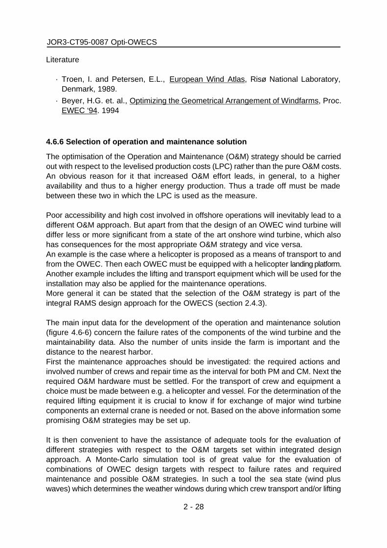
JOR3-CT95-0087 Opti-OWECS
2 - 28
Literature
· Troen, I. and Petersen, E.L., European Wind Atlas, Risø National Laboratory, Denmark, 1989.
· Beyer, H.G. et. al., Optimizing the Geometrical Arrangement of Windfarms, Proc. EWEC ‘94. 1994
4.6.6 Selection of operation and maintenance solution
The optimisation of the Operation and Maintenance (O&M) strategy should be carried out with respect to the levelised production costs (LPC) rather than the pure O&M costs. An obvious reason for it that increased O&M effort leads, in general, to a higher availability and thus to a higher energy production. Thus a trade off must be made between these two in which the LPC is used as the measure. Poor accessibility and high cost involved in offshore operations will inevitably lead to a different O&M approach. But apart from that the design of an OWEC wind turbine will differ less or more significant from a state of the art onshore wind turbine, which also has consequences for the most appropriate O&M strategy and vice versa. An example is the case where a helicopter is proposed as a means of transport to and from the OWEC. Then each OWEC must be equipped with a helicopter landing platform. Another example includes the lifting and transport equipment which will be used for the installation may also be applied for the maintenance operations. More general it can be stated that the selection of the O&M strategy is part of the integral RAMS design approach for the OWECS (section 2.4.3). The main input data for the development of the operation and maintenance solution (figure 4.6-6) concern the failure rates of the components of the wind turbine and the maintainability data. Also the number of units inside the farm is important and the distance to the nearest harbor. First the maintenance approaches should be investigated: the required actions and involved number of crews and repair time as the interval for both PM and CM. Next the required O&M hardware must be settled. For the transport of crew and equipment a choice must be made between e.g. a helicopter and vessel. For the determination of the required lifting equipment it is crucial to know if for exchange of major wind turbine components an external crane is needed or not. Based on the above information some promising O&M strategies may be set up. It is then convenient to have the assistance of adequate tools for the evaluation of different strategies with respect to the O&M targets set within integrated design approach. A Monte-Carlo simulation tool is of great value for the evaluation of combinations of OWEC design targets with respect to failure rates and required maintenance and possible O&M strategies. In such a tool the sea state (wind plus waves) which determines the weather windows during which crew transport and/or lifting

Integrated Design Methodology for OWECS
2 - 29
operations is possible and also the different failures of the all OWEC's in the offshore wind farm are simulated according to a stochastic process based upon the reliability data of the OWEC components and the site characteristics. The results of the O&M simulation are the involved O&M costs and an estimate of the costs of energy. Based on the outcome of evaluation of the O&M strategies the wind turbine design may be reconsidered, especially the reliability data and the maintenance intervals.
Literature
· Bussel, van G.J.W., Schöntag, C., Operation and maintenance aspects of large offshore windfarms, Proc. EWEC '97. 1997.
4.7. Step 4: Design specification and preparation of construction
Star t
C o n s i d e r a t i o n o f m a i n t e n a n c e a p p r o a c h ( e . g . P M & C M , o n l y P M , o n l y C M )
C o n s i d e r a t i o n o f O & M h a r d w a r e • t r a n s p o r t e q u i p m e n t • l i f t i n g a n d m a i n t e n a n c e e q u i p m e n t
E v a l u a t i o n o f O & M b e h a v i o u r • a v a i l i b i l i t y , e n e r g y y i e l d , • l o a d i n g o f c r e w s a n d e q u i p m e n t , • O & M c o s t s
C o n s i d e r a t i o n o f O & M s t r a t e g y ( e . g . O p p o r t u n i t y b a s e d )
O & M s t r a t e g y a n d h a r d w a r e
E n d
W i n d t u r b i n e d e s i g n ( re l iab i l i ty , mainta in ib i l i ty data )
O W E C S d a t a ( s i t e , f a r m a n d e c o n o m i c d a t a )

JOR3-CT95-0087 Opti-OWECS
2 - 30
In the final step of the design process the procurement, construction, installation and commissioning is prepared. Interactions between sub-systems is limited since design loads, dimensions and interfaces are specified. Control focuses on following of these directives and on the organisation of the implementation phase (‘Who does what, when, where and together with whom?’). Since an large OWECS comprises a considerable number of (nearly) identical units the management of the procurement and manufacturing aspects involves a significant potential for cost reduction. The step is not further elaborated here since much experience in the different fields of the sub-systems already exists and should be followed.

Integrated Design Methodology for OWECS
2 - 1
5. First application of the integrated design approach Although the integrated OWECS design approach described in section 3.4 and chapter 3 is one final result of the Opti-OWECS project most of its essentials have already been considered during the design work carried out in the two years course of the project. Here a brief review on this first application is given with the intention to demonstrate its feasibility and its prospects for future applications. In contrast to the comprehensive documentation of the design process and its solution in [5.1] here the procedure and some main experiences are mentioned.
Project identification The initial phase of the project identification has comprised three aspects, the establishment of the project group and the determination of project conditions (i.e. objectives and work programme) and of particular design conditions. One key issue is seen in the group of participants which provides knowledge on all necessary aspects:
· engineering experience in the fields of wind energy, offshore technology and offshore wind energy,
· cost optimisation of wind turbines, · projects on (offshore) wind farms, · operation of power plants and energy distribution.
In addition, the partners have been selected with respect to their complementary roles e.g. the background of manufacturers and designers is linked with that of researchers. Next, the project objectives and work programme have been formulated carefully not only to convince the client, i.e. the European Commission, but also to state realistic goals. For instance, both the integration of economic and structural optimisation and the simultaneous consideration of wind turbine and support structure has only been proposed for the second year of the project when sufficient experience from the separate treatment of the sub-systems during the first year had become available. During the project kick-off the design objectives have been agreed upon:
· demonstration of a practical design solution for commercial, large-scale OWECS to be built 5 - 10 years from now,
· minimum levelised production costs as operational goal of the OWECS, · application of an integrated design approach.
In addition, a number of particular design conditions have been determined, e.g. wind turbine size ≥ 3 MW, neglecting of onshore grid connection aspects, etc.

JOR3-CT95-0087 Opti-OWECS
2 - 2
Feasibility study During the first project phase, which was in fact a feasibility study (figure 5.1), a broad inventory of all relevant aspects/concepts has been performed and selections for the conceptual design have been made. The results have been assembled in a reference document and are presented in [5.2]. Furthermore, a particular terminology appropriate to OWECS has been established in order to effect a smooth communication (appendix A).
The identification of distinctly different reference sites in northern European waters has been carried out in parallel to the investigation of sub-system concepts and of essentials of overall dynamics and operation and maintenance aspects. Based upon a qualitative OWECS evaluation the sub-system concepts for the further development have been selected:
· wind turbine concepts (geared - fixed speed, direct-drive - variable speed), · rotor variants with diameters between 80 and 100 m and different rotor speeds, · distinctly different combinations of support structure configuration, dynamic
characteristics, installation procedure and site, · base cases for grid connection and wind farm layout
Conceptual design The conceptual design phase (figure 5.2) has been largely carried out as parallel work on sub-systems and development/extension of OWECS tools, i.e. cost model, O&M
Start: Feasibi l i ty study
4 suppor t structure &
2 instal lat ion types
Essentials of O & M
1 w i n d turb ine
base case
Pre-se lect ion of OWECS sub-system concepts
Essentials of gr id
connect ion & fa rm layout
Pre-select ion of 6 European
sites
Essentials of dynamics
Qual i ta t ive OWECS evaluat ion
End: Feasibi l i ty study
Select ion: 2 turbine concepts & rotor var iants,
several combinat ions of : support structure, insta l la t ion procedure,
dynamic characterist ics & site

Integrated Design Methodology for OWECS
2 - 3
simulation, structural reliability considerations and overall dynamics. Improved knowledge on particular OWEC aspects gained during the phase, i.e. combined wind and wave loading, extreme wave loads on gravity based support structures in shallow waters have led to the consideration of a third support structure concept distinctly different from the two other ones.
Particular innovations directly related to the integrated approach include:
· integrated development of support structure concepts and installation procedure, · simultaneous optimisation of wind turbine (rotor speed, blade layout) and support
(i.e. structure stiffness) with the main goal of reduction of aerodynamic fatigue loads,
· consideration of overall dynamics of OWEC in the support structure design, · development of O&M strategies based on Monte-Carlo simulations, · development of structural reliability analysis for an OWEC support structure.
Most results of the parallel work are presented by [5.3]. Next, the novel OWECS cost model has been used to evaluate different OWECS assembled from the developed sub-systems concepts (see conceptual design) and the six pre-selected sites (see feasibility study) with respect to the quantitative design objectives, i.e. minimum levelised production costs. The economic performance together with some other criteria has led to the selection of the final OWECS concept and the related site.
Structural design During the structural design phase the selected concept has further been worked out and interactions between sub-systems have been fully considered (figure 5.3).
Conceptual sub-system
design
Selection of final concept and site
Development of OWECS cost model
Extension of overall dynamics of
OWEC
OWECS evaluation (cost model & other criteria):
comparison of various concepts at 6 sites
Development of O&M
simulation
Start: Conceptual design
End: Conceptual design
Development of structural reliability for OWEC support
structure

JOR3-CT95-0087 Opti-OWECS
2 - 4
This integration facilitated several achievements: · improvements on reliability, availability, maintainability and serviceability of the wind
turbine simultaneously to the development of the operation and maintenance strategy,
· further significant cost reduction of the support structure and the installation procedure due to close cooperation between structural design and dynamic simulations of the OWEC,
· balance of aerodynamic efficiency of the wind farm and cable cost of the grid connection,
· optimum placement of the OWEC transformer based on consideration of wind turbine, support structure and grid connection aspects.
The structural design phase has been concluded with a detailed economic analysis and parameter study on important cost drivers which confirmed the potential of the solution.
It should be noted that neither during the structural design phase nor after the final evaluation of the design solution major design changes were required because the conceptual design has already been checked in detail with respect to technical feasibility and economic performance.
Design specification No establishment of tender documents has been carried out since this was beyond the scope of the project.
Concluding remarks Essential aspects of the integrated OWECS design approach have been applied successfully within a design situation during the Opti-OWECS project. Beside the technical feasibility and economic prospects it has also been demonstrated that such a methodology can be managed within an international cooperation of scientists and industry engineers from wind energy technology, offshore technology and energy management.
Final sub-system
design
O W E C S economics
Overall dynamics o f O W E C
Economic assessment & parameter study
O&M simulation
Start: Final design
End: Final design

Integrated Design Methodology for OWECS
2 - 5


Integrated Design Methodology for OWECS
2 - 1
6. Conclusions
Offshore wind farm system Only the OWECS as one entire system can provide a considerable amount of electric power in a reliable and cost-efficient way over the projected lifetime and with the demanded quality and persistence. Therefore four objectives for an optimum OWECS design can be stated which are related to the nature of such a system:
· optimum distribution of investment and operation and maintenance (O&M) costs over the entire OWECS and its lifetime
· high reliability of OWECS as a whole and of essential sub-systems · adaptation to economy of scale and partial redundancy of single OWEC units · symbioses of experience from wind energy and offshore technology
Design practices in wind energy and offshore technology Obviously OWECS design should be based on the experience in wind energy as well as offshore technology. However, one has to be aware of the different backgrounds and sometimes even contradictory principles in these two engineering fields. Apart from the different expertise on aerodynamics and hydrodynamics, respectively, the parent technologies are offering opportunities for a symbiosis in offshore wind energy application. As there are by the wind energy technology
· cost-reduction due to series production · importance of dynamics especially fatigue · weight reduction due to structural flexibility and dynamic response
and by the offshore technology
· fit-for-purpose design due to adaptation on the particular site conditions · transportation, installation and operation & maintenance as main cost drivers · probabilistic design methods e.g. structural reliability considerations · experience with and financial resources for large projects in the billion ECU range
OWECS design approaches Three different, exemplary OWECS design approaches have been identified: the traditional or robust, the parallel and finally the integrated approach. There is no free choice between them because the approaches are ordered by increasing complexity and understanding of OWECS and they depend on the experience gained with their predecessor.

JOR3-CT95-0087 Opti-OWECS
2 - 2
The traditional or robust approach fits the objectives of the prototype projects but is not suitable for the proposed large scale offshore wind farms because even for sites in sheltered waters with reduced wave loading the economics are likely to be poor. The parallel approach might be typically adopted for the design of demonstration or (near) commercial plants and is regarded as promising if strong experience is available at sub-system level. The integrated design approach is seen as the required solution for the first commercial, large offshore wind farms to be erected by the beginning of the new millennium.
Integrated OWECS design approach Other suitable design methodologies undoubtedly exist, but it is expected that an OWECS design based on an ‘integrated design approach’ will most probably be nearer to optimal in both technical and economic sense. The integrated design approach considers the components of an offshore wind farm only as parts of the entire system i.e. the OWECS. Therefore interactions between sub-systems are considered as complete and practical as possible and the design solution is governed by overall criteria / aspect-systems such as: global economics, actual site conditions, entire system dynamics, structural reliability considerations, transportation / installation as well as operation and maintenance strategies. Within the proposed variants of the integrated approach the ‘design for RAMS’ (Reliability, Availability, Maintainability and Serviceability) and the ‘radical design’ have particular prospects. The former offers double benefits by increasing energy yield and cutting down operation & maintenance costs. Ultimately radical design might facilitate further significant reduction of capital costs and/or O&M costs. However, unproven or just ‘big’ designs, do not lend themselves well for application in the demanding offshore environment. Although the radical approach may be needed for very large offshore wind farms with capacities up to the gigawatt range it is not considered feasible at the moment. It is believed that this step can only be taken if there is enough experience with the integrated approach in general. A first and quite successful application of the integrated OWECS design approach has been demonstrated by the development of the OWECS design solution within the Opti-OWECS project.

Integrated Design Methodology for OWECS
2 - 1
7. Recommendations for further development and outlook Although first experience with an integrated approach on OWECS design has been gained during Opti-OWECS obviously such a methodology needs continuous further development by usage in desk-top studies as well as implementation projects. Under the conditions and constraints of large ‘real’ projects it has to be found out in which form the integrated approach is suitable to the complexity of the OWECS as well of the organisation and process of the design. Moreover it has to be realised that the proposed design approach is only the shell around the interaction of various activities, tools and expertise rather than a goal for its own. The incorporation of legal constraints, political decision points and interaction with public opinion should be considered. The proposed wind turbine design approach ‘Design for RAMS approach’ has not been followed so far and its procedural as well as scientific development is a worthwhile study for its own.


Integrated Design Methodology for OWECS
2 - 1
8. References [1.1] Kühn, M.; Bierbooms, W.A.A.M.; van Bussel, G.J.W.; Ferguson, M.C.;
Göransson, B.; Cockerill, T.T; Harrison, R.; Harland, L.A.; Vugts, J.H.; Wiecherink, R. Opti-OWECS Final Report Vol. 0: Executive Summary. Institute for Wind Energy, Delft University of Technology, 1998.
[1.2] Kühn, M. (editor), Cockerill, T.T; Harland, L.A.; Harrison, R.; Schöntag, C.; van
Bussel, G.J.W.; Vugts, J.H. Opti-OWECS Final Report Vol. 2: Methods Assisting the Design of Offshore Wind Energy Conversion Systems. Institute for Wind Energy, Delft University of Technology, 1998.
[1.3] Cockerill, T.T.; Harrison, R.; Kühn, M.; van Bussel, G.J.W.; Opti-OWECS Final
Report Vol. 3: Estimate of Costs of Offshore Wind Energy at European Sites. Institute for Wind Energy, Delft University of Technology, 1998.
[1.4] Ferguson, M.C. (editor); Kühn, M.; Bierbooms, W.A.A.M.; Cockerill, T.T;
Göransson, B.; Harland, L.A.; van Bussel, G.J.W.; Vugts, J.H.; Hes, R. Opti-OWECS Final Report Vol. 4: A Typical Design Solution for an Offshore Wind Energy Conversion System. Institute for Wind Energy, Delft University of Technology, 1998.
[1.5] T.T. Cockerill, Opti-OWECS Final Report Vol. 5: User Guide OWECS Cost
Model. Institute for Wind Energy, Delft University of Technology, 1998. [1.6] Kühn, M.; Terminology, Reference Systems and Conventions to be used within
the Opti-OWECS Project.; Institute for Wind Energy IW96.097R, Delft University of Technology, 1996.
[2.1] Lenning, J., The Danish 4000 MW Offshore Programme. Proc. EWEC’97. [2.2] Bruijne, de R., The Netherlands Market: A Trend towards Large Scale
Applications. Proc. EWEC ‘97. [3.1-1] Kühn, M., Pauling, T., Köhler, S. Cost Analysis and Optimization of Offshore
Wind Farms. Proc. EUWEC‘96 [3.2-1] Quarton, D.C., et.al. Wind Turbine Design Calculations - The State of the Art.
Proc. EUWEC ‘96. [3.3-1] Ridder, de H.A.J., “Design and Construct” of Complex Civil Engineering
Systems; a New Approach to Organisation and Contracts. Delft University Press, Delft, 1994.

JOR3-CT95-0087 Opti-OWECS
2 - 2
[3.3-2] Madsen, P.S. Tunø Knob Offshore Wind Farm. Proc. EUWEC ‘96. [3.3-3] Annon. I/S Midtkraft, Arhus, 10 x Vestas V 39 off-shore. In: Wind-Kraft Journal
Vol. 15, 4/95. pp.10 -14. 1995. [3.3-4] Olsen, F., Ramussen, K. Experience from the Construction and Operation of
Vindeby Offshore Wind Farm. Proc. OWEMES ‘94 Seminar Rome, Italy. 1994. [3.3-5] Kouwenhoven, H.J. et.al., Wind farm Lely - The first offshore wind farm in the
Netherlands. Proc. EWEC '94. [3.3-6] Månsson, K.J. Pilot Plant for Offshore Windpower. Proc. EWEC, 91. Van
Hülle, Smulders, Dragt ( eds.); Elsevier Science Publishers B.V., pp. 446-448. 1991.
[3.3-7] Kühn, M., Dynamics of Offshore Wind Energy Converters on a Monopile
Foundation - Design Study based on the First Dutch Offshore Wind Farm. Institute for Wind Energy (IW96.093R), Delft University of Technology, 1996.
[3.4-1] Germanischer Lloyd. Regulations for the Certification of Wind Energy Conversion Systems. German. Lloyd, Hamburg, Edition 1993, modified 1995.
[3.4-2] Germanischer Lloyd. Regulations for the Certification of Offshore Wind
Energy Conversion Systems. German. Lloyd, Hamburg. 1995. [3.4-3] IEC. IEC 1400-1 Safety of Wind Energy Generator Systems. 1994. [3.4-4] see [1-4] [3.4-5] Grievink, J., Smit, K., Dekker, R., Rijn, C.F.H. van, Managing Reliability and
Maintenance in the Process Industry. Proc. 2nd Int. Conf. On Foundations of Computer-Aided Process Operations. Rippin, D.W.T.; Halle, J.C., Davis, J.F. (editors). Crested Butte, Colorado, July 18-23 1993, pp133-158. 1993.
[3.4-6] Kuik, van, G., Sherwin, R.W. The Ultimate Wind Turbine: A Minimum Cost
and Maintenance Turbine. Proc. EUWEC ‘96.
[3.4-7] Jamieson, P., et.al. Advanced Wind Turbine Design. Proc. EWEC ‘94. [3.4-8] Deijl, van T.J., Vries, de E., MultiWind Turbine; Energiecentrale voor de 21ste
eeuw. (In Dutch, with English summary). 1996

Integrated Design Methodology for OWECS
2 - 3
[3.4-9] Halfpenny, A., et.al. A Technical Feasibility Study and Economic Assessment of n Offshore Floating Wind Farm. Proc. BWEA ‘95. 1995.
[3.4-10] Bakker, C.; Coelingh, J.P.; Arkesteijn, L.A.G. Winds of Change - A Feasibility Study of 10,000 MW Offshore Wind Energy in the North Sea. Adviesbureau E-Connection BV. Delft. Rep. E66-REP5.NOX. May 1997.
[4.2-1] see [3.3-1] [4.2-2] NOVEM. Haalbaarheidsstudie demonstratieproject nearshore wind park.
Executive Summary. NOVEM. 1997 (in Dutch) [4.4-1] Matthies, H.G., et.al. Study of Offshore Wind Energy in the EU. Bristol,
Hamburg, Verlag Natürliche Energien, 1995. [4.5-1] Kühn, M. (editor), et. al., Opti-OWECS Final Report Vol. 2: Methods Assisting
the Design of Offshore Wind Energy Conversion Systems. Institute for Wind Energy, Delft University of Technology, 1998.
[4.6-1] Quarton, D. C.; Wastling, M. A. Wind and Wave Loading of Offshore Wind
Turbines. Proc. EUWEC '93 Bedford, H.S. Stephens & Associates, 1993, pp.575 - 578.
[4.6-2] Kühn, M., Simulation of Offshore Wind Turbines under Stochastic Loading.
Proc. EWEC ‘94. [4.6-3] see [1-4] [5.1] see [1-4] [5.2] Kühn, M., et.al. Structural and Economic Optimization of Offshore Wind
Energy Converters - Overview and Results of the First Phase. Proc. EUWEC ‘96. Göteborg, Sweden. 1996.
[5.3] Kühn, M., et.al. Structural and Economic Optimization of Offshore Wind
Energy Converters - Overview on Progress in the Joule III Project Opti-OWECS. Proc. OWEMES '97 Conference, La Maddalena (Sardinia), Italy.
idem: Wind Engineering, Vol. 21, Nr. 4, 1997. [A.1] Kühn, M. Terminology, Reference Systems and Conventions to be used within
the Opti-OWECS Project. Delft Univ. of Technology, Institute for Wind Energy. Report IW 96.097R. 1996.

JOR3-CT95-0087 Opti-OWECS
2 - 4
[B.1] Cockerill, T.T., et.al. , Part A - Economic Comparison of Design Options. In: Kühn, M. (editor), et. al., Opti-OWECS Final Report Vol. 2: Methods Assisting the Design of Offshore Wind Energy Conversion Systems. Institute for Wind Energy, Delft University of Technology, 1998.
[B.2] Schöntag, C., Bussel, van G.J.W. Part B - Optimization of Operation and
Maintenance. In: Kühn, M. (editor), et. al., Opti-OWECS Final Report Vol. 2: Methods Assisting the Design of Offshore Wind Energy Conversion Systems. Institute for Wind Energy, Delft University of Technology, 1998.
[B.3] Graaf, van de, J.W., Tromans, P.S. Statistical Verification of Predicted Loading
and Ultimate Strength against Observed Storm Damage from an Offshore Structure. Proc. Offshore Technology Conference 1991, Paper OTC 6573, Houston, USA, 1991.
[B.4] Tromans, P.S., Graaf, van de, J.W. A Substantial Risk Assessment of an Jacket Structure. Proc. Offshore Technology Conference 1992, Paper OTC 7075, Houston, USA, 1992.
[B.5] Tromans, P.S., Vanderschuren, L. Response based Design Conditions in the North Sea: Application of a New Method. Proc. Offshore Technology Conference 1995, Paper OTC 7683, Houston, USA, 1995.
[B.6] Harland, L.A., Vugts, J.H., Part C - Reliability Methods. In: Kühn, M. (editor),
et. al., Opti-OWECS Final Report Vol. 2: Methods Assisting the Design of Offshore Wind Energy Conversion Systems. Institute for Wind Energy, Delft University of Technology, 1998.
[B.7] Kühn, M., Part D - Overall Dynamics of OWECS. In: Kühn, M. (editor), et. al.,
Opti-OWECS Final Report Vol. 2: Methods Assisting the Design of Offshore Wind Energy Conversion Systems. Institute for Wind Energy, Delft University of Technology, 1998.

Integrated Design Methodology for OWECS
2 - 1
Appendix A: OWECS Terminology Offshore wind energy is a fairly new and multi-discipline field. Unfortunately no uniform terminology exist and and misunderstandings can occur quite easily. Therefore within the Opti-OWECS project one has agreed upon a particular terminology, conventions and reference systems in order to make the internal and external communication more effective. Here only the shortened version of more complete document is precented [A.1]. Preface In principle, the common practice concerning notation and convention within the considered disciplines i.e. wind engineering, offshore technology and engineering economics should be used. However, harmonisation is required in the description of the entire system and its components, the interfaces between sub-systems and the structural design. The two former aspects are treated in this paper. 1 Offshore wind energy conversion system (OWECS) offshore wind energy conversion system (OWECS)
Entire system, comprising (usually) several wind energy converter units, for conversion of wind energy into electric power including the wind turbines, the support structures, the grid connection to the power delivery point and operation and maintenance aspects. Note that the environment i.e. air, water and soil as well as the utility grid are not considered as a part of the OWECS.
offshore wind farm
synonym for OWECS 2 Main OWECS components offshore wind energy converter (OWEC)
single unit of the OWECS comprising electro-aeromechanical conversion system (wind turbine) and support structure 11
11 No plural of the abbreviation ‘OWEC’ should not be used instead one may use ‘OWEC units’, full out spelling or the singular form ‘OWEC’, if possible.

JOR3-CT95-0087 Opti-OWECS
2 - 2
wind turbine (WT) Component of an offshore wind energy converter that transforms wind energy into electric power on generator voltage or AC-rectifier voltage, comprising rotor, nacelle with entire interior, control and safety system and electrical turbine system.12
support structure (bottom-mounted)
Structure that supports the wind turbine and transfers the loading into the soil. Hence, the support structure comprises both the tower and the foundation.
grid connection
Electrical system that takes the power provided at the turbine connection points and collects it at the wind farm collection point(s) and successively transmits it to the onshore connection point with the public grid.
operation and maintenance aspects
auxiliary facilities, equipment and strategy required for operation, maintenance, control and administration of an OWECS
12 Note the term 'wind turbine' should be used with care since it is often also used with a wider meaning i.e. rotor and nacelle together with the tower, foundation and sometimes even the transformer from the generator to the collection voltage. In external communication one should be sure that the audience is aware of the above mentioned definition. The term 'offshore wind turbine(s)' should not be used in order to avoid confusion whether one refers to an offshore wind energy converter system (OWECS), an offshore wind energy converter (OWEC) or even only the electro-aeromechanical conversion system.
offshore wind energy conversion system (OWECS) +- offshore wind energy converter (OWEC) ¦ +- wind turbine (WT) ¦ +- support structure +- grid connection +- operation and maintenance aspects

Integrated Design Methodology for OWECS
2 - 3
3 Boundaries of OWECS components wind turbine and support structure
The fixed end of the yaw mechanism of the nacelle is defined as boundary between the (horizontal axis) wind turbine and the support structure. All geometric and dynamic conditions are expressed with respect to the reference frame of the support structure.
wind turbine and grid connection
The turbine switch gear or circuit breaker at the tower base is defined as boundary between electrical system of the turbine and the grid connection. The voltage at the connection point corresponds to the generator or the inverter (if any). Although a transformer might be installed at the wind energy converter unit it is regarded as part of the grid connection.
grid connection and utility grid
The power of the OWECS is provided as three-phase AC at the voltage level of the utility grid to which the wind farm is connected. In absence of other explicit conventions the connection point is situated at the first dry location onshore regardless the actual grid infrastructure on land.
4 OWECS sub-components and boundaries between them The sub-components of the main parts of an OWECS are defined by figure A.2. Tower and foundation
The separation of the support structure into the tower and the foundation depends on the kind of foundation which is either of the piled, gravity or skirted type and might also be influenced by manufacturing and installations consideration. For certain integrated designs (e.g. an integrated monopile) a separation into tower and foundation might not be applicable. As a general rule for piled designs only the actual piles are denoted as foundation. For the gravity type, the foundation consists of the structural part(s) which transfer(s) the loading into the soil and that obtain resistance against the overturning moment i.e. usually the caisson.
OWECS +- wind turbine (WT) ¦ +- rotor ¦ +- (mechanical) drive train ¦ +- nacelle ¦ +- control and safety system ¦ +- electrical turbine system +- support structure ¦ +- tower ¦ +- foundation +- grid connection ¦ +- power collection ¦ +- power transmission +- operation and maintenance aspects
+- maintenance facilities and equipment +- control, safety and
administration facilities +- operation and maintenance strategy

JOR3-CT95-0087 Opti-OWECS
2 - 4
Power collection and power transmission The boundary between the power collection and power transmission is located at the point where the total power is collected that is transmitted by one transmission line to shore. The voltage level at the connection point is that of the power collection lines.

Integrated Design Methodology for OWECS
2 - 5


Integrated Design Methodology for OWECS
2 - 1
Appendix B: Methods assisting the design of OWECS In the section 2.4 the integrated OWECS design approach has been recognized as a promising method. However, the development of certain ‘building blocks’ is required to enable the desired step beyond the state-of-the-art. In the following four of such contributions are briefly reviewed while other relevant issues like optimisation of installation and verification of OWECS design methods, etc. will not be treated here. The complete description of these methods is provide by the different parts of Vol. 2 of the final Opti-OWECS report. B.1. Concept analysis and cost modelling In contrast to land based wind farms, at offshore locations the main sub-systems i.e. wind turbine, support structure and grid connection contribute in approximately equal shares to the investment. Moreover, the interaction between capital costs and maintenance costs is likely to result in different overall configurations that are optimal offshore, probably favouring simple robust systems with the minimum of complex mechanisms. Interaction between machine costs and support structural and electrical transmission costs will favour optimal solutions with large multi-megawatt machines. Different wind regimes offshore, different wind shear and other extreme wind speeds will affect optimal tower height and other aspects of machine design. Generally a certain OWECS design will be optimum only with respect to a particular site. All these aspects can neither be considered prior to the design process nor on a level of detail engineering. Therefore, a concept analysis including an economic optimization of the preliminary design, as developed in Opti-OWECS Task 2.1 [B.1], is an important part of the entire design process. Furthermore an OWECS cost model can be used for a pre-selection of promising sites and to judge the prospects of modifications of sub-systems with respect to the overall performance. One particular advantage is the capability of balancing conflicting goals e.g. high availability / production versus low O&M costs. B.2. Simulation of the operational behaviour of OWECS With respect to the evaluation of the O&M behaviour of OWECS and certainly if the design should met stated targets for RAMS (Reliability, Availability, Maintainability and Serviceability) it is appropiate to apply design tools for reliability and availability calculations. Such design tools range from simple probabilistic techniques for simplified reliability and availability calculations based upon generic failure rates, to more advanced

JOR3-CT95-0087 Opti-OWECS
2 - 2
Markov chain modelling. Exact calculations are however only possible for simplified systems. For complex systems such as an OWECS the most often applied technique for evaluation of the O&M process are Monte-Carlo simulations. The input for such calculations is taken from the conceived technical design of the OWEC unit, the available OWECS infrastructure and with it the impact of the conceived maintenance concept can be investigated. With such O&M simulations it is possible to verify the targets with respect to reliability and availability of the OWECS, which have a direct impact on the possibility to achieve the product targets at the required cost. It is then possible and necessary to evaluate this targets (on the systems level), and if needed subsequently modify the specifications on the sub-systems level. In the course of the Opti-OWECS project a simulation tools for O&M behaviour of OWECS has been developed and used successfully [B.2]. B.3. Structural reliability considerations To optimize structural design the correlation of wind and wave (and current) loads is essential in the analysis of the behaviour of an OWEC support structure under survival conditions. Obviously the conventional superposition of the extreme load components, each with the same return period (e.g. 50 or 100 years), is far too conservative. In recent years probabilistic methods have been developed for the assessment of offshore structures for the petroleum industry, that are based on the statistics of the extreme response over the lifetime in combination with a desired minimum reliability against failure [B.3, 4, 5]. Inherently such an approach provides a design adaptation with respect to the site conditions since it is based on large databases with information about all relevant environmental parameters e.g. hindcasted met-ocean data13, valid for the actually considered location. In combination with an OWECS cost model (see previous section) the failure costs including loss in production can be balanced against capital costs. In the Opti-OWECS project such novel structural reliability methods have been used for the very first time in an (offshore) wind energy project [B.6]. Therefore the application will be used for to the support structure only; however, in principle it seems to be possible to adapt the treatment also to the wind turbine sub-system. B.4. Overall dynamics of OWEC
13A met-ocean database is a set of wave, current and wind data (magnitudes and directions) representing the local environment over a period of time, for example 25 years, that is derived from meteorological data using hindcast techniques. The oceanographic data have been computed using wind fields derived from atmospheric pressure distributions. Field measurements have been used to calibrate the models.

Integrated Design Methodology for OWECS
2 - 3
The dynamic properties of an OWEC and its complex loading results in interactions between several sub-systems. Certain phenomena e.g. drive train dynamics are restricted to only some components while other e.g. support structure fatigue, aerodynamic damping, controller and generator behaviour require a model of the entire OWEC or even inclusion of certain OWECS aspects (e.g. wake or electrical interactions within the wind farm). Therefore, the dynamics of the overall system should be investigated by modal analysis as well as by dynamic response analysis [B.7]. In the latter case time domain simulations capable are used which are in principle well-suited to include unsteady and non-linear effects. Appendix C: Overview on some relevant design standards and guidelines In order to provide a better orientation within the different technologies relevant for OWECS here a incomplete list of design standards and guidelines is given. Comments given to certain documents reflect the subjective meaning of the author.
Offshore wind energy technology · Germanischer Lloyd. Regulations for the Certification of Offshore Wind Energy
Conversion Systems. German. Lloyd, Hamburg. 1995. The only OWECS standard so far, developed during a previous European project on offshore wind energy JOUR 0072.
Wind energy technology (International) · IEC. IEC 1400-1 ed. 2 Safety of Wind Energy Generator Systems. 1998. The only international standard for wind energy conversion systems. Widely used by the industry. Note ed 2 is yet only in a final draft mode. IEC 1400-1 ed 1 is a IEC standard but not accepted as a standrad within Europe (CENELEC-area).
· Tande, O.J. , Hunter R. (editors), Recommended Practices for Wind Turbine
Testing and Evaluation. Vol. 2: Estimation of Cost of Energy from Wind Energy Conversion Systems. Risø National Laboratory, Denmark and Renewable Energy Unit, UK. 1994.
Although this document is no design standard is comprises quite useful information on economic aspects of wind energy conversion systems.
Wind energy technology (Denmark)

JOR3-CT95-0087 Opti-OWECS
2 - 2
· The Danish Society of Engineers and the Federation of Engineers. Loads and Safety of Wind Turbine Construction - Danish Standard DS 472. 1st edition. Secretariat for Type-Approval Risø, Denmark. May 1992.
Wind energy technology (Germany) · Germanischer Lloyd. Regulations for the Certification of Wind Energy Conversion
Systems. German. Lloyd, Hamburg, Edition 1993, modified 1995. German wind turbine standard (excluding tower design) largely compatible with IEC 1400-1.
· DIBt (Deutsches Institut für Bautechnik). Richtlinie für Windkraftanlagen -
Einwirkungen und Standsicherheitsnachweise für Turm und Gründung. edition June 1993. DIBt, Berlin.
German standard valid for tower and foundation which included simplified fatigue load description and a gust response factor. · DIN 4133 Schornsteine aus Stahl (Steel stacks). Nov. 1991 Useful for the establishment of aerodynamic drag coefficients and of particular details of the tower design e.g. door entry.
· DIN 4131 Antennentragwerke aus Stahl (Steel radio towers and masts). Nov. 1991 Useful for the establishment of detail categories (fatigue reference stress) of steel tower, etc..
Wind energy technology (The Netherlands) · Rademakers, L.W.M.M., Regulations for the type-certification of wind turbines:
Technical Criteria Ontwerp NVN 11400/0 (Draft). ECN. ECN-R--97-005. 1997. Compatible with IEC 1400-1 ed.1 but also used for type-certification in the Netherlands and contains requirements for noise, energy production, type testing , etc.
Offshore Technology · API RP2A-LRFD, API Recommended Practices for Planning, Designing and
Constructing Fixed Offshore Platforms - Load and Resistance Factor Design. First Edition, July 1, 1993.
Widely used standard which includes various guidelines. Often applied for foundation design e.g. pile-soil interaction. Less conservative partial safety factors on material related to soil data than compared with the OWECS guidelines of GL.
· Det Norske Veritas. Rules for Classification - Rules for Fixed Offshore Structures
(DNV Rules). Det Norske Veritas Classification A/S. Høvik. July 1995. Widely used standard.

Integrated Design Methodology for OWECS
2 - 3
· Germanische Lloyd. Rules for Classification and Construction - Offshore Technology, Part 2 Offshore Installations, 2 Volumes, Hamburg 1990.
· Department of Energy. Offshore Installations: Guidance on Design, Construction
and Certification. London. HMSO, 4th edition, 1990. Guidelines which provide a comprehensive hints on application of design methods, load assumption, terminology, etc.
· Department of Energy. Fluid Loading on Fixed Offshore Structures. WS Atkins,
Epson, Surrey, 1987.
· API RP2N, API Recommended Practices for Planning, Designing and Constructing Structures for Arctic Conditions. Second Edition, December 1, 1995.
Provides a comprehensive description of ice loads (especially by first edition).

JOR3-CT95-0087 Opti-OWECS
2 - 4
Power engineering
· IEC. IEC Standard Voltages. IEC 38. 1983.
· IEC. Power quality requirements for Grid Connected Wind Turbines (Working Draft
#6 230697). International Electrotechnical Commission. TC 88: Wind Turbine Generator Systems. Working Group 10.
· Richtlijnen voor harmonische stromen geproduceert door apparatuur met een
vermogen groter dan 11 kVA. Uitgave EnergieNed Jan. 1996.

Integrated Design Methodology for OWECS
2 - 5


Integrated Design Methodology for OWECS
2 - 1
Appendix D: Example database for the OWECS design process The conceptual as well as the structural design of an OWECS is done in parallel for the different sub-systems. During this process data of certain sub-systems (e.g. dimensions, weight, qualities, interface definitions, loads, etc.) are required for the design of other sub-systems. However, at the same time the properties of the sub-systems designs are often altered as a fact of the process. Likewise sites are changed and the rough description of the considered site(s) becomes more specific. Therefore for a smooth design process it is essential to ensure a proper up-date and prompt distribution of the OWECS data to all participants. A database for the OWECS design process maintained by the project coordinator is a convenient solution for this problem. In the following an example of such a data collection is given. It should be noted that the extent of the database will increase over time. Furthermore that tables should included only the data which are of importance to the parallel design of other sub-systems rather than ‘all’ design data.
Table D1: Economic and other general parameters
Scenario 1
Scenario 2
Scenario 3
interest rate
economic life time
N.N.
Table D2: Site data
Site 1
Site 2
Site 3
Name
Geographical coordinates
Available area [km x km]
Annual mean wind speed [m/s]
Water depth (LAT) range [m]
Distance from shore [km]
Owner of site
Wind speed distribution (reference) - (directional) Weibull parameter

JOR3-CT95-0087 Opti-OWECS
2 - 2
- wind rose Extreme wind speed [m/s] - annual 5 s gust - annual 1 min gust - 50 years 5 s gust - 50 years 1 min gust
Wind shear parameter - normal - extreme
Extreme surge [m]
Tidal range [m]
Significant wave height [m] - return period 1 a - return period 50 a - at rated wind speed e.g. 15 m/s - at cut-out wind speed e.g. 25 m/s
Wave scatter diagram (reference)
Design current [m/s] - tidal current - wind current
Design ice - thickness [m] -properties
Soil type and profile
Soil properties e.g. - P-y curves (reference) - mechanical properties
Scour
Distance to infrastructure - grid connection point - harbour, etc.
Specification grid connection point - voltage - maximum acceptable short circuit current
N.N.

Integrated Design Methodology for OWECS
2 - 3
Table D3: Wind turbine data
Design 1
Design 2
Design 3
Type, version
Rotor diameter [m]
No. of blades [-]
Rotor speed(s) (range) [rpm]
Rated electrical power [kW]
Rotor and nacelle weight [t]
Centre of gravity (x, y, z) [m]
Tilt angle [deg]
Rotor overhang [m] (tower centre to hub centre along rotor axis)
(Vertical) nacelle offset [m] (tower top centre to rotor axis)
Max. lateral outstand of support structure for clearance of blade tip [m]
Min. vertical clearance between walkway and obstacles and blade tip [m]
Specification tower top interface - dimension - max. allowed inclination
CP-? curve, P-v curve (reference)
Drive train efficiency (partial/ full load)
CDax-? curve, thrust curve (reference)
Tower top loads at stand-still - normal - failure
Equivalent tower top fatigue loads
Generator voltage [V] - rated value - acceptable tolerance
cos f [-]
short circuit current [A]
MTBF (Mean Time Between Failure) [h]

JOR3-CT95-0087 Opti-OWECS
2 - 4
Preventive Maintenance interval [h] Noise emission
N.N.
Table D4: Support structure data
Design 1
Design 2
Design 3
Type, version
Overall height above mudline [m]
Penetration depth [m]
Gross dimensions
Eigenfrequencies (rotor horizontally resp. vertically)
Structural damping
Tower top stiffness matrix
Tower dimensions for tower shadow effects
Tower dimensions for internal equipment
N.N.
Table D5: Installation procedure data
Design 1
Design 2
Design 3
max. allowed inclination of nacelle
max. allowed acceleration of nacelle/rotor
gross dimensions of modules e.g. wind turbine, tower, pile, etc.
design environmental conditions (for installation)
N.N.

Integrated Design Methodology for OWECS
2 - 5
Table C5: Grid connection data
Design 1
Design 2
Design 3
Type, version
Total no. of OWEC
Configuration (star, circuit, line, etc.)
Voltage levels [kV]
Cluster size [-]
Transformer dimension and weight - OWEC transformer (if any) - Cluster transformer (if any) - Central transformer (if any)
Switch gear, etc. dimension and weight - OWEC - Cluster - Central
Cables - rated power - maximum current
Transmission efficiency - partial load - full load
N.N.
Table D6: Wind farm layout data
Design 1
Design 2
Design 3
Type, version
Configuration
Turbine spacing
Efficiency
Wake effect (increase in turbulence)
N.N.

JOR3-CT95-0087 Opti-OWECS
2 - 6
Table D7: Operation & Maintenance data
Design 1
Design 2
Design 3
Type, version
Assumed reliability data of OWECS
PM schedule
lifting equipment (might be also suitable for installation)
Typical range of OWEC availability