Operator’s/Parts Manual: TD1 Transfer Deck Option (Master)
20
Transfer Deck Safety, Operation, Maintenance & Parts Manual TD1 rev. A1.00 - A4.00 Safety is our #1 concern! Read and understand all safety information and instructions before oper- ating, setting up or maintaining this machine. Form #1062 !
Transcript of Operator’s/Parts Manual: TD1 Transfer Deck Option (Master)

Transfer DeckSafety, Operation,
Maintenance & Parts Manual
TD1 rev. A1.00 - A4.00
Safety is our #1 concern! Read and understandall safety information and instructions before oper-ating, setting up or maintaining this machine.
Form #1062
!

Table of Contents Section-Page
SECTION 1 SAFETY 1-11.1 Safety Symbols.......................................................................................1-11.2 Safety Instructions ..................................................................................1-2
SECTION 2 GENERAL INFORMATION 2-1
2.1 Transfer Deck Components....................................................................2-1
SECTION 3 PNEUMATIC CONTROL BOX 3-1
3.1 Technical Data........................................................................................3-13.2 Connecting The Control Box..................................................................3-13.3 Maintenance ...........................................................................................3-23.4 Quickly-Wearing Components...............................................................3-23.5 Control Box Components .......................................................................3-33.6 Pneumatics Diagram...............................................................................3-5
SECTION 4 REPLACEMENT PARTS 4-1
4.1 Table Assembly ......................................................................................4-14.2 Board Stop/Air Bag Assembly ...............................................................4-24.3 Kicker & Air Cylinder............................................................................4-44.4 Lower Frame ..........................................................................................4-5
SECTION 5 ELECTRICAL INFORMATION 5-1
5.1 Electrical Symbol Diagram ....................................................................5-15.2 Electrical Component List ......................................................................5-2
ii TD02doc071805 Table of Contents

SafetySafety Symbols
Safety TD02doc071805 1-1
1SECTION 1 SAFETY
1.1 Safety Symbols
The following symbols and signal words call your attention to instructions concerning yourpersonal safety. Be sure to observe and follow these instructions.
DANGER! indicates an imminently hazardous situationwhich, if not avoided, will result in death or serious injury.
WARNING! suggests a potentially hazardous situationwhich, if not avoided, could result in death or serious injury.
CAUTION! refers to potentially hazardous situations which,if not avoided, may result in minor or moderate injury ordamage to equipment.
IMPORTANT! indicates vital information.
NOTE: gives helpful information.
Warning stripes are placed on areas where a single decalwould be insufficient. To avoid serious injury, keep out ofthe path of any equipment marked with warning stripes.
!

SafetySafety Instructions1
1.2 Safety Instructions
NOTE: ONLY safety instructions regarding personal injury are listed in this section. Cau-tion statements regarding only equipment damage appear where applicable throughoutthe manual.
OBSERVE SAFETY INSTRUCTIONS
IMPORTANT! Read the entire Operator's Manual before operatingthe transfer deck. Take notice of all safety warnings throughout thismanual and those posted on the machine. Keep this manual withthis machine at all times, regardless of ownership.
Also read any additional manufacturer’s manuals and observe anyapplicable safety instructions including dangers, warnings, andcautions.
Only persons who have read and understood the entire operator'smanual should operate the transfer deck. The transfer deck is notintended for use by or around children.
IMPORTANT! It is always the owner's responsibility to comply withall applicable federal, state and local laws, rules and regulationsregarding the ownership, operation of your Wood-Mizer products.All Wood-Mizer product owners are encouraged to become thor-oughly familiar with these applicable laws and comply with themfully while using the machine.
!
1-2 TD02doc071805 Safety

SafetySafety Instructions 1
KEEP TRANSFER DECK AND AREA AROUND TRANSFER DECK CLEAN
DANGER! Maintain a clean and clear path for all necessary move-ment around the machine and lumber stacking areas. Failure to doso will result in serious injury.
CAUTIONS FOR TRANSFER DECK SETUP
WARNING! Securely fasten the feet of the transfer deck to the floorbefore operating the machine. Failure to do so may result in seri-ous injury or death.
Safety TD02doc071805 1-3
SafetySafety Instructions1
CHECK TRANSFER DECK BEFORE OPERATION
DANGER! Make sure all guards and covers are in place andsecured before operating the transfer deck. Failure to do so mayresult in serious injury.
KEEP PERSONS AWAY
WARNING! Keep all persons out of the path of movingequipment and boards while operating transfer deck. Fail-ure to do so may result in serious injury or death.
1-4 TD02doc071805 Safety

SafetySafety Instructions 1
USE PROPER PROCEDURE WHEN CONDUCTING ELECTRICAL SAFETY CHECKSAND MAINTENANCE
DANGER! Make sure all electrical installation, service and/ormaintenance work is performed by a qualified electrician and is inaccordance with applicable electrical codes.
WARNING! Consider all electrical circuits energized and danger-ous.
WARNING! Never assume or take the word of another person thatthe power is off; check it out and lock it out.
WARNING! Do not wear rings, watches, or other jewelry whileworking around an open electrical circuit.
Safety TD02doc071805 1-5
General InformationTransfer Deck Components2
2-1 TD02doc071805 General Information
SECTION 2 GENERAL INFORMATION
2.1 Transfer Deck Components
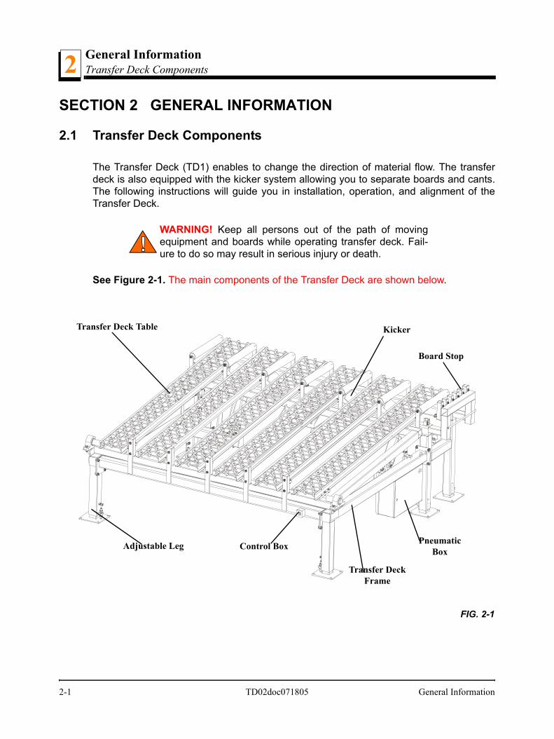
The Transfer Deck (TD1) enables to change the direction of material flow. The transferdeck is also equipped with the kicker system allowing you to separate boards and cants.The following instructions will guide you in installation, operation, and alignment of theTransfer Deck.
WARNING! Keep all persons out of the path of movingequipment and boards while operating transfer deck. Fail-ure to do so may result in serious injury or death.
See Figure 2-1. The main components of the Transfer Deck are shown below.
FIG. 2-1
Transfer Deck Table
Board Stop
Kicker
Control BoxAdjustable Leg
Transfer DeckFrame
PneumaticBox

Technical Data 3
SECTION 3 PNEUMATIC CONTROL BOX3.1 Technical Data
See Table 3-1.
3.2 Connecting The Control Box
When delivered, the control box is completely assembled and tested for air tightnessand electrical connection.
Perform the following steps to get the control box ready for work:
connect compressed air to the ball valve,
connect the control box to the pneumatic system,
connect the control system to the terminal block,
open the ball valve and set the working pressure to .6 MPa,
fill the lubricator with oil (insert the end of the lubricator hose into a container withoil, push the red button, fill the lubricator up to the line marked on it and release thered button).
Duty Cycle Continuous operation
Weight 17 kg
Working Medium Compressed air
Maximum Pressure 0,9 MPa
Working Pressure 0,6 MPa
Filter Porosity 40 m
Temperature 0oC do +50oC
Supply Voltage For Solenoid Valves 24 V DC +/- 10%
TABLE 3-1
µ
TD02doc071805 3-1

Maintenance3
3.3 MaintenanceFollow the following instructions to ensure proper control box functioning:
Check the lubricator oli level every month. Add oil as necessary.
Always check the working pressure after connecting the control box. If necessary,adjust it with the knob on the filter regulator.
Every month make sure the filter cartridge is clean. Replace the cartridge if it is verydirty.
3.4 Quickly-Wearing Components
Filter Cartridge
3-2 TD02doc071805

Control Box Components 3
3.5 Control Box ComponentsTD02doc071805 3-3

Control Box Components3
1 - Ball Valve,2 - Air Service Assembly,
3 - Lubricator,
4 - Time Relay,
5 - Coil, 24V DC,
6 - Electrical Connector,
7 - Mechanical Pressure Switch,
8 - Solenoid Valve, 3/2 G1/4” 24V DC Monostable,
9 - Solenoid Valve, 5/2 G1/2” 24V DC Monostable,
10 - Connector,
11 - Choke Valve,
12 - Silencer,
13 - Metal Box,
14 - Pressure Gauge (located on the box door),
15 - Terminal Block,
16 - Fitting For Air Cylinder Manifolds,
17 - Fitting For Air Bag.
18- Control Console (WM# 095006)
3-4 TD02doc071805

Pneumatics Diagram 3
3.6 Pneumatics DiagramThe transfer deck air system is shown below.
Air Bag
23A
B
EX
INAir Supply 70-90PSIFilter to 40 Micron
Air Cyliners
1
TD02doc071805 3-5

Table Assembly4
4-1 TDdoc071805
SECTION 4 REPLACEMENT PARTS
4.1 Table Assembly
REF DESCRIPTION ( Indicates Parts Available In Assemblies Only) PART # QTY.
TABLE ASSEMBLY, TRANSFER DECK 089760 1
1 Conveyor, Roller 034150 6
2 Tube Weldment, Transfer Deck Table 089721-1 1
3 Bolt, M8x35 -8.8 Hex Head Full Thread Zinc F81002-13 36
4 Nut, M8-8-B Zinc Hex F81032-1 44
5 Washer, 8.4 Zinc Flat F81054-1 80
6 PLATE, LOWER TABLE STOP 089778 2
7 BUMPER, MET-GUM RUBBER 089728 4
8 BOLT, M8x25-8.8-B HEX HEAD FULL THREAD ZINC F81002-5 4
9 BEARING, UCP 210 CX 089041 2
10 BOLT, M12x55-8.8 HEX HEAD ZINC F81004-12 4
11 WASHER, 13 ZINC FLAT F81056-1 8
12 NUT, M12-8 HEX NYLON ZINC LOCK F81034-2 4
td0006c
1
2
3
45
1011
12
4
5
6
7
8
4
4

Replacement PartsBoard Stop/Air Bag Assembly 4
4.2 Board Stop/Air Bag Assembly
REF DESCRIPTION ( Indicates Parts Available In Assemblies Only) PART # QTY.
1 FRAME WELDMENT, ROLLER 089725-1 1
2 Spring, 21D.x38x2 Zinc-Plated 087040 4
3 Pin, Outrigger Pull Zinc-Plated 087012-1 4
4 Pin, 4x50 Roll Zinc F81044-6 4
5 Pin, 8x65 Roll Zinc F81046-1 4
6 Washer, 20.5 Split Lock Zinc F81059-1 4
7 ROLLER, 76,L=600,L1=663 W/M12 THREADED ROD 095160 7
8 WASHER, 13 FLAT ZINC F81056-1 14
9 NUT, M12-8-B HEX NYLON ZINC LOCK F81034-2 14
td0031-4
1
2
3456
78
9
10
11
12
13
14
15 16
17
1819
20
2122
2024
2526
23
27
Replacement Parts TDdoc071805 4-2

Replacement PartsBoard Stop/Air Bag Assembly4
10 BUMPER, MET-GUM RUBBER 089728 8
11 NUT, M8-8-B HEX ZINC F81032-1 8
12 STOP WELDMENT, BOARD 089746-1 1
13 BUMPER, #054B RUBBER 089717 6
14 BOLT, M10x40-8.8 HEX HEAD FULL THREAD ZINC F81003-16 12
15 WASHER, 10.5 FLAT ZINC F81055-1 12
16 NUT, M10-8-B HEX NYLON ZINC LOCK F81033-1 12
17 BAG, 192 308 100 0 AIR 088576 1
18 FITTING, G1/4XG3/4 088572 1
19 BOLT, M12x170-8.8 HEX HEAD ZINC F81004-7 2
20 NUT, M12-8-B HEX ZINC F81034-1 6
21 WASHER, 10.5 FLAT ZINC F81055-1 2
22 NUT, M12-8 HEX NYLON ZINC LOCK F81034-2 2
23 LEG WELDMENT, TD BASE 089766-1 4
24 BOLT, M12x40-8.8 HEX HEAD FULL THREAD ZINC F81004-4 4
25 WASHER, 20.5 SPLIT LOCK ZINC F81059-1 4
26 NUT, M20-8 HEX ZINC F81037-1 8
27 CONTROL BOX, TRANSFER DECK 091532 1
PNEUMATIC COMPONENTS (EXCEPT CONTROL BOX) 091353 1
4-3 TDdoc071805 Replacement Parts

Replacement PartsKicker & Air Cylinder
Replacement Parts TDdoc071805 4-4
44.3 Kicker & Air Cylinder
REF DESCRIPTION ( Indicates Parts Available In Assemblies Only) PART # QTY.
1 TUBE WELDMENT, KICKER 089737-1 1
2 BEARING, UCP211 CX PILLOW BLOCK 089738 2
3 BOLT, M16x60 8.8 HEX HEAD FULL THREAD ZINC F81006-12 4
4 WASHER, 17 FLAT ZINC F81058-1 8
5 NUT, M16-8 HEX NYLON ZINC LOCK F81036-2 4
6 CYLINDER, AIR 091497 2
7 BOLT, M10x140-8.8 HEX HEAD ZINC F81003-5 8
8 WASHER, 10.5 FLAT ZINC F81055-1 16
9 NUT, M10-8-B HEX NYLON ZINC LOCK F81033-1 8
td0003b
1
3
4
2
5
6
7
8
9
3
4
2
5
6
7
8
9

Replacement PartsLower Frame4
4-5 TDdoc071805 Replacement Parts
4.4 Lower Frame
REF DESCRIPTION ( Indicates Parts Available In Assemblies Only) PART # QTY.
1 TUBE WELDMENT, FRAME LEFT SIDE 089753-1 1
2 TUBE WELDMENT, FRAME RIGHT SIDE 089749-1 1
3 TUBE WELDMENT, FRAME CROSS 089715 1
4 BUMPER, #054B RUBBER 089717 5
5 BOLT, M10x60-8.8 HEX HEAD ZINC F81003-10 10
6 WASHER, 10.5 FLAT ZINC F81055-1 10
7 NUT, M10-8-B HEX NYLON ZINC LOCK F81033-1 10
8 BOLT, M12X35-8.8 HEX HEAD FULL THREAD ZINC F81004-24 16
9 WASHER, 13 FLAT ZINC F81056-1 32
10 NUT, M12-8 HEX NYLON ZINC LOCK F81034-2 16
11 BOLT, M12X40-8.8 HEX HEAD FULL THREAD ZINC F81004-4 2
12 NUT, M12-8-B HEX ZINC F81034-1 2
13 LEG WELDMENT, TD BASE 089766-1 2
14 WASHER, 20.5 SPLIT LOCK ZINC F81059-1 2
15 NUT, M20-8 HEX ZINC F81037-1 4
td0031-2c
8 910
1
2
345
6
7
8 9
10
1112
131415

Electrical InformationElectrical Symbol Diagram
Electrical Information TDdoc071805 5-1
5SECTION 5 ELECTRICAL INFORMATION
5.1 Electrical Symbol Diagram
FIG. 5-1
1112
A2
A1
P1
El1
El 2
XUK
-24V
DC
(53
)
ŻÓŁTY
BRĄZOWY
ZIELONY
AU
TO
PR
MAN
UA
L
53 A
Wid
ok złą
cza
czuj
nika
XU
K
12 3
4
BRĄ
ZOW
Y
ŻÓŁT
YZI
ELO
NY
BIAŁY
+24V
DC
(55
)

Electrical InformationElectrical Component List4
4-2 TDdoc071805 Electrical Information
5.2 Electrical Component List
Component Manufacturer Wood-Mizer Part No.
Description
PR Switch, Operation ModeXUK 093169 Sensor, Photo TransmitterP1 090515 Relay, AuxiliaryEl1 Valve, Air Bag SolenoidEl2 Solenoid Valve, Air Cylinders
TABELA 5-1