
Operator's Manual Second Edition • Third Printing...Operator's Manual Second Edition · Third...
68
Transcript of Operator's Manual Second Edition • Third Printing...Operator's Manual Second Edition · Third...


Operator's Manual Second Edition • Third Printing
Z-135/70 Part No. 114474
Copyright © 2005 by Terex Corporation
Second Edition: Third Printing, January 2013
"Genie" and "Z" are registered trademarks ofTerex South Dakota in the U.S.A. and manyother countries.
These machines comply withANSI/SIA 92.5CAN B.354.4
Printed on recycled paper
Printed in U.S.A.
ImportantRead, understand and obey these safety rules andoperating instructions before operating this machine.Only trained and authorized personnel shall bepermitted to operate this machine. This manualshould be considered a permanent part of yourmachine and should remain with the machine at alltimes. If you have any questions, call us.
ContentsPage
Introduction ................................................................ 1Symbols and Hazard Pictorials Definitions ................. 3General Safety ........................................................... 5Personal Safety ........................................................ 11Work Area Safety...................................................... 12Legend ...................................................................... 20Controls .................................................................... 21Inspections ............................................................... 29Operating Instructions ............................................... 46Transport and Lifting Instructions .............................. 57Maintenance ............................................................. 60Specifications ........................................................... 63
Contact us:Internet: http://www.genielift.come-mail: [email protected]

Operator's ManualSecond Edition · Third Printing
Part No. 114474 Z-135/70 1
Introduction
DangerFailure to obey the instructions andsafety rules in this manual willresult in death or serious injury.
Do Not Operate Unless:You learn and practice the principles of safemachine operation contained in this operator'smanual.
1 Avoid hazardous situations.Know and understand the safety rules beforegoing on to the next section.2 Always perform a pre-operation inspection.
3 Always perform function tests prior to use.
4 Inspect the workplace.
5 Only use the machine as it was intended.
You read, understand and obey themanufacturer's instructions and safety rules—safety and operator's manuals and machinedecals.
You read, understand and obey employer'ssafety rules and work site regulations.
You read, understand and obey all applicablegovernmental regulations.
You are properly trained to safely operate themachine.
Owners, Users and Operators:Genie appreciates your choice of our machine foryour application. Our number one priority is usersafety, which is best achieved by our joint efforts.We feel that you make a major contribution tosafety if you, as the equipment users andoperators:
1 Comply with employer, job site andgovernmental rules.
2 Read, understand and follow the instructionsin this and other manuals supplied with thismachine.
3 Use good safe work practices in acommonsense way.
4 Only have trained/certified operators, directedby informed and knowledgeable supervision,running the machine.
If there is anything in this manual that is not clearor which you believe should be added, pleasecontact us.

Operator's Manual Second Edition · Third Printing
2 Z-135/70 Part No. 114474
Intended UseThis machine is intended to be used only to liftpersonnel, along with their tools and materials to anaerial work site.
Introduction
Safety Sign MaintenanceReplace any missing or damaged safety signs.Keep operator safety in mind at all times. Use mildsoap and water to clean safety signs. Do not usesolvent-based cleaners because they may damagethe safety sign material.
Hazard ClassificationGenie uses symbols, color coding and signal wordsto identify the following:
Safety alert symbol—used to alertyou to potential personal injuryhazards. Obey all safetymessages that follow this symbolto avoid possible injury or death.
Indicates a hazardous situationwhich, if not avoided, will result indeath or serious injury.
Indicates a hazardous situationwhich, if not avoided, could resultin death or serious injury.
Indicates a hazardous situationwhich, if not avoided, could resultin minor or moderate injury.
Indicates a hazardous situationwhich, if not avoided, could resultin property damage.
Red
Orange
Yellow
Blue

Operator's ManualSecond Edition · Third Printing
Part No. 114474 Z-135/70 3
Symbol and Hazard Pictorials Definitions
Explosion Hazard
ElectrocutionHazard
Fall Hazard
Crush Hazard
Tip-over Hazard
Tip-over Hazard
Tip-over Hazard ElectrocutionHazard
Maintain requiredclearance.
Read the operator’smanual.
Keep off thissurface.
Keep away frompath of movingplatform.
No smoking.No flame.Stop engine.
Do not use etheror other highenergy startingaids on machinesequipped withglow plugs.
Read servicemanual
Rated platformcapacity
Platform uphill:1 Lower primary2 Retract/lower
secondary3 Retract primary
Platform downhill:1 Retract primary2 Retract/lower
secondary3 Lower primary
3
3
Recovery procedure if tilt alarm soundswhile elevated.
Only trainedmaintenancepersonnel shouldaccesscompartments
Crush Hazard Keep away frommoving parts.
Explosion Hazard
Disconnect battery.
Operator's Manual Second Edition · Third Printing
4 Z-135/70 Part No. 114474
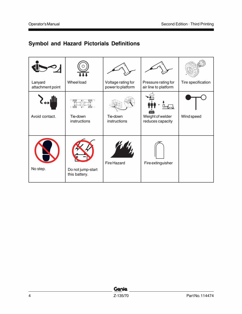
Symbol and Hazard Pictorials Definitions
Lanyardattachment point
Wheel load Voltage rating forpower to platform
Pressure rating forair line to platform
Avoid contact. Tie-downinstructions
Tie-downinstructions
Fire extinguisher
Weight of welderreduces capacity
Wind speed
No step. Do not jump-startthis battery.
Fire Hazard
Tire specification

Operator's ManualSecond Edition · Third Printing
Part No. 114474 Z-135/70 5
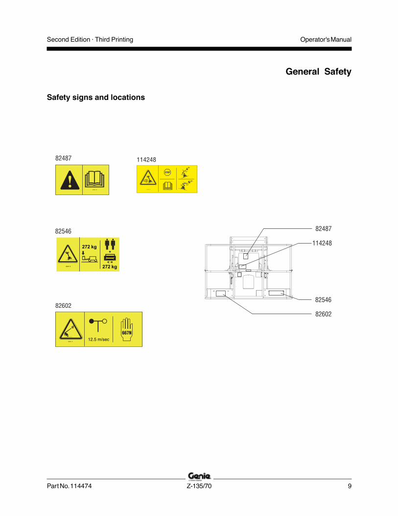
Safety signs andlocations
General Safety
Lug Nut TorqueDry bolts:
420 ft-lbs /569.5 Nm
Lubricated bolts:320 ft-lbs /433.9 Nm
Tip-over HazardFailure to replace tires with tiresof same specification will resultin death or serious injury.
Do not use air-filled tires.Foam-filled tires are critical tomachine stability.
Do not replace factory-installedtires with tires of differentspecification or ply rating.Tire Size445/65 D22.5, 18 ply Foam-filled
DANGER
97715 B
Electrocution/Burn HazardFailure to disconnect allthe batteries beforeperforming service on thismachine may result indeath or serious injury.
Disconnect all the batteriesbefore performing service onthis machine.
WARNING
97865 B

Operator's Manual Second Edition · Third Printing
6 Z-135/70 Part No. 114474
General Safety
Safety signs and locations
Bodily Injury HazardFailure to use pipe cradle assembly according to instructions and safety rulesbelow and in operator's and responsibilities manual could result in death orserious injury.Do not exceed rated platform capacity.Pipe cradle assembly and weight in pipecradles will reduce rated platform capacityand must be factored into total platformload.
Pipe cradle assembly weighs 25 lbs (11kg).
Maximum capacity of pipe cradle assemblyis 200 lbs (91 kg).
Weight of pipe cradle assembly and load inpipe cradles may limit maximum number ofoccupants in platform.
Center load within perimeter of platform.
Secure load to platform.
Do not obstruct entrance/exit of platform.
Do not obstruct ability to operate platformcontrols or Emergency Stop button.
Do not operate unless you are adequatelyinstructed and are aware of all hazardsassociated with movement of platformwith overhanging load.
Do not cause a horizontal force or sideload to machine by raising or lowering afixed or overhanging load.
!"#$%$&
72875 C
Do not cause a horizontal forceor side load to machine byraising or lowering a fixed oroverhanging load.
Maximum vertical height ofpanels: 4 ft / 1.2 m
Maximum wind speed:15 mph / 6.7 m/sec
Maximum panel area:32 sq. ft / 3 m2
Do not exceed rated platformcapacity. Combined weightof cradles, panels,occupants, tools and anyother equipment must notexceed rated capacity.
Panel cradle assemblyweighs 30 lbs / 13.6 kg.
Maximum capacity of panelcradles is 250 lbs / 113 kg.
Weight of panel cradles and loadin panel cradles may limitmaximum number of occupantsin platform to one person.
Secure cradles to platform.Secure panel(s) to platformrailing using straps provided.
Do not operate unless you areadequately instructed and areaware of all hazards associatedwith lifting panels.
WARNING
82410 C
Bodily InjuryHazard
Failure to use panel cradles according to instructions and safety rulesbelow and in operator's and responsibilities manual could result in deathor serious injury.
Tip-over HazardIf tilt-alarmsounds, unit is ona severe slope.Death or seriousinjury will result.
133236 A
DANGER
Platform uphill:1 Lower primary boom.2 Retract/lower secondary boom.3 Retract primary boom.
Platform downhill:1 Retract primary boom.2 Retract/lower secondary boom.3 Lower primary boom.
3
3
• Read operator'smanual beforeattempting to movemachine.
• Stop all movement.

Operator's ManualSecond Edition · Third Printing
Part No. 114474 Z-135/70 7
Safety signs and locations
General Safety
Electrocution/Burn HazardFailure to disconnect allthe batteries beforeperforming service on thismachine may result indeath or serious injury.
Disconnect all the batteriesbefore performing service onthis machine.
WARNING
97865 B
Tip-over HazardAltering or disabling angle sensorcan result in machine tip-over.Machine tip-over will result indeath or serious injury.
DANGER
Do not move, alter or disableangle sensor.
82314 B
Lug Nut TorqueDry bolts:
420 ft-lbs /569.5 Nm
Lubricated bolts:320 ft-lbs /433.9 Nm
Tip-over HazardFailure to replace tires with tiresof same specification will resultin death or serious injury.
Do not use air-filled tires.Foam-filled tires are critical tomachine stability.
Do not replace factory-installedtires with tires of differentspecification or ply rating.Tire Size445/65 D22.5, 18 ply Foam-filled
DANGER
97715 B

Operator's Manual Second Edition · Third Printing
8 Z-135/70 Part No. 114474
General Safety
Safety signs and locations
133179 A
Operator's ManualSecond Edition · Third Printing
Part No. 114474 Z-135/70 9
General Safety
Safety signs and locations
82546 B
272 kg+
< =272 kg

Operator's Manual Second Edition · Third Printing
10 Z-135/70 Part No. 114474
General Safety
Safety signs and locations
133179 A
133180 A

Operator's ManualSecond Edition · Third Printing
Part No. 114474 Z-135/70 11
Personal Safety
Fall ProtectionPersonal fall protection equipment (PFPE) isrequired when operating this machine.
Occupants must wear a safety belt or harness inaccordance with governmental regulations. Attachthe lanyard to the anchor provided in the platform.
Operators must comply with employer, job site andgovernmental rules regarding the use of personalprotective equipment.
All PFPE must comply with applicablegovernmental regulations, and must be inspectedand used in accordance with the PFPEmanufacturer’s instructions.

Operator's Manual Second Edition · Third Printing
12 Z-135/70 Part No. 114474
Work Area Safety
Electrocution HazardsThis machine is notelectrically insulatedand will not provideprotection from contactwith or proximity toelectrical current.
Maintain safe distancesfrom electrical powerlines and apparatus inaccordance withapplicablegovernmentalregulations and thefollowing chart.
Line Voltage Required Clearance
0 to 50KV 10 ft 3.0 m
50 to 200KV 15 ft 4.6 m
200 to 350KV 20 ft 6.1 m
350 to 500KV 25 ft 7.6 m
500 to 750KV 35 ft 10.6 m
750 to 1000KV 45 ft 13.7 m
Allow for platform movement, electrical line sway orsag and beware of strong or gusty winds.
Keep away from the machine if it contactsenergized power lines. Personnel on the ground orin the platform must not touch or operate themachine until energized power lines are shut off.
Do not use the machine as a ground for welding.
Do not operate the machine during lightning orstorms.
Before performing service on this machine,disconnect the batteries under both turntablecovers.
Tip-over HazardsOccupants, equipment and materials shall notexceed the maximum platform capacity.
Maximum platform capacity 600 lbs 272 kg
Maximum occupants 2
The weight of options and accessories, such aspipe cradles, panel cradles and welders, will reducethe rated platform capacity and must be subtractedfrom the platform capacity. See the decals with theoptions and accessories.
If using accessories, read, understand and obeythe decals, manuals and instructions with theaccessory.
Operator's ManualSecond Edition · Third Printing
Part No. 114474 Z-135/70 13
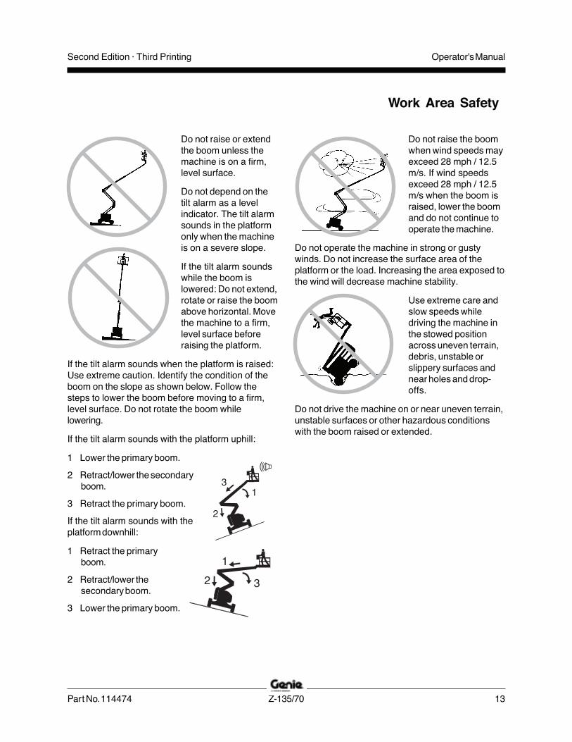
Do not raise or extendthe boom unless themachine is on a firm,level surface.
Do not depend on thetilt alarm as a levelindicator. The tilt alarmsounds in the platformonly when the machineis on a severe slope.
If the tilt alarm soundswhile the boom islowered: Do not extend,rotate or raise the boomabove horizontal. Movethe machine to a firm,level surface beforeraising the platform.
If the tilt alarm sounds when the platform is raised:Use extreme caution. Identify the condition of theboom on the slope as shown below. Follow thesteps to lower the boom before moving to a firm,level surface. Do not rotate the boom whilelowering.
If the tilt alarm sounds with the platform uphill:
1 Lower the primary boom.
2 Retract/lower the secondaryboom.
3 Retract the primary boom.
If the tilt alarm sounds with theplatform downhill:
1 Retract the primaryboom.
2 Retract/lower thesecondary boom.
3 Lower the primary boom.
Do not raise the boomwhen wind speeds mayexceed 28 mph / 12.5m/s. If wind speedsexceed 28 mph / 12.5m/s when the boom israised, lower the boomand do not continue tooperate the machine.
Do not operate the machine in strong or gustywinds. Do not increase the surface area of theplatform or the load. Increasing the area exposed tothe wind will decrease machine stability.
Use extreme care andslow speeds whiledriving the machine inthe stowed positionacross uneven terrain,debris, unstable orslippery surfaces andnear holes and drop-offs.
Do not drive the machine on or near uneven terrain,unstable surfaces or other hazardous conditionswith the boom raised or extended.
Work Area Safety
Operator's Manual Second Edition · Third Printing
14 Z-135/70 Part No. 114474
Work Area Safety
Do not use air-filled tires. These machines areequipped with foam-filled tires. Wheel weight iscritical to stability.
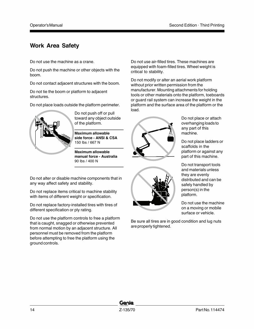
Do not modify or alter an aerial work platformwithout prior written permission from themanufacturer. Mounting attachments for holdingtools or other materials onto the platform, toeboardsor guard rail system can increase the weight in theplatform and the surface area of the platform or theload.
Do not place or attachoverhanging loads toany part of thismachine.
Do not place ladders orscaffolds in theplatform or against anypart of this machine.
Do not transport toolsand materials unlessthey are evenlydistributed and can besafely handled byperson(s) in theplatform.
Do not use the machineon a moving or mobilesurface or vehicle.
Be sure all tires are in good condition and lug nutsare properly tightened.
Do not use the machine as a crane.
Do not push the machine or other objects with theboom.
Do not contact adjacent structures with the boom.
Do not tie the boom or platform to adjacentstructures.
Do not place loads outside the platform perimeter.
Do not push off or pulltoward any object outsideof the platform.
Maximum allowableside force - ANSI & CSA150 lbs / 667 N
Maximum allowablemanual force - Australia90 lbs / 400 N
Do not alter or disable machine components that inany way affect safety and stability.
Do not replace items critical to machine stabilitywith items of different weight or specification.
Do not replace factory-installed tires with tires ofdifferent specification or ply rating.
Do not use the platform controls to free a platformthat is caught, snagged or otherwise preventedfrom normal motion by an adjacent structure. Allpersonnel must be removed from the platformbefore attempting to free the platform using theground controls.
Operator's ManualSecond Edition · Third Printing
Part No. 114474 Z-135/70 15
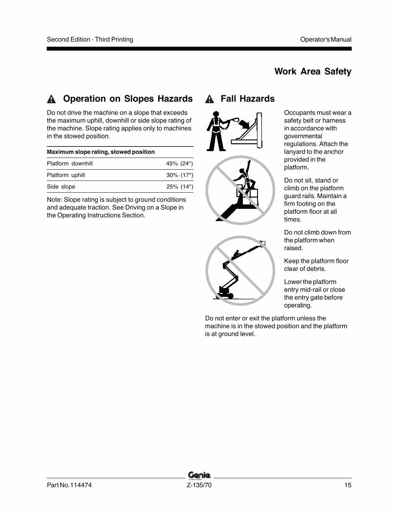
Fall HazardsOccupants must wear asafety belt or harnessin accordance withgovernmentalregulations. Attach thelanyard to the anchorprovided in theplatform.
Do not sit, stand orclimb on the platformguard rails. Maintain afirm footing on theplatform floor at alltimes.
Do not climb down fromthe platform whenraised.
Keep the platform floorclear of debris.
Lower the platformentry mid-rail or closethe entry gate beforeoperating.
Do not enter or exit the platform unless themachine is in the stowed position and the platformis at ground level.
Operation on Slopes HazardsDo not drive the machine on a slope that exceedsthe maximum uphill, downhill or side slope rating ofthe machine. Slope rating applies only to machinesin the stowed position.
Maximum slope rating, stowed position
Platform downhill 45% (24°)
Platform uphill 30% (17°)
Side slope 25% (14°)
Note: Slope rating is subject to ground conditionsand adequate traction. See Driving on a Slope inthe Operating Instructions Section.
Work Area Safety

Operator's Manual Second Edition · Third Printing
16 Z-135/70 Part No. 114474
Collision Hazards
Be aware of limited sight distance and blind spotswhen driving or operating.
Be aware of the boom position and tailswing whenrotating the turntable.
Be aware of machine length when operating. Themachine is 42 ft 5 inches / 12.9 m long.
Check the work area foroverhead obstructionsor other possiblehazards.
Be aware of crushinghazards when graspingthe platform guard rail.
Operators must complywith employer, job siteand governmental rulesregarding the use ofpersonal protectiveequipment.
Observe and use thecolor-coded directionarrows on the platformcontrols and drivechassis for drive andsteer functions.
Do not operate a boom in the path of any craneunless the controls of the crane have been lockedout and/or precautions have been taken to preventany potential collision.
No stunt driving orhorseplay whileoperating a machine.
Do not lower the boomunless the area belowis clear of personneland obstructions.
Limit travel speedaccording to thecondition of the groundsurface, congestion,slope, location ofpersonnel, and anyother factors whichmay cause collision.
Bodily Injury HazardDo not operate the machine with a hydraulic oil orair leak. An air leak or hydraulic leak can penetrateand/or burn skin.
Always operate the machine in a well-ventilatedarea to avoid carbon monoxide poisoning.
Improper contact with components under any coverwill cause serious injury. Only trained maintenancepersonnel should access compartments. Accessby the operator is only advised when performing apre-operation inspection. All compartments mustremain closed and secured during operation.
Work Area Safety

Operator's ManualSecond Edition · Third Printing
Part No. 114474 Z-135/70 17
Work Area Safety
Explosion and Fire HazardsDo not start the engine if you smell or detect liquidpetroleum gas (LPG), gasoline, diesel fuel or otherexplosive substances.
Do not refuel the machine with the engine running.
Refuel the machine and charge the battery only inan open, well-ventilated area away from sparks,flames and lighted tobacco.
Do not operate the machine in hazardous locationsor locations where potentially flammable orexplosive gases or particles may be present.
Do not spray ether into engines equipped with glowplugs.
Damaged Machine HazardsDo not use a damaged or malfunctioning machine.
Conduct a thorough pre-operation inspection of themachine and test all functions before each workshift. Immediately tag and remove from service adamaged or malfunctioning machine.
Be sure all maintenance has been performed asspecified in this manual and the appropriate Genieservice manual.
Be sure all decals are in place and legible.
Be sure the operator’s, safety and responsibilitiesmanuals are complete, legible and in the storagecontainer located on the platform.
Component Damage HazardsDo not use any battery or charger greater than 12Vto jump-start the engine. Apply jumper cables to thestarter and controls battery, not the auxiliary powerbatteries.
Do not use the machine as a ground for weldingunless the machine is equipped with the weld lineto platform option and it is properly connected.
Battery Safety
Burn HazardsBatteries contain acid.Always wear protectiveclothing and eye wearwhen working withbatteries.
Avoid spilling orcontacting battery acid.Neutralize battery acidspills with baking sodaand water.
Explosion Hazard
Keep sparks, flamesand lighted tobaccoaway from batteries.Batteries emitexplosive gas.
Electrocution HazardAvoid contact with electrical terminals.

Operator's Manual Second Edition · Third Printing
18 Z-135/70 Part No. 114474
Pipe Cradle Safety
Read, understand and obey all warnings andinstructions provided with the pipe cradles.
Do not exceed the rated platform capacity. Thepipe cradle assembly and the weight in the pipecradles will reduce rated platform capacity andmust be factored into total platform load.
The pipe cradle assembly weighs 21 lbs / 9.5 kg.
The maximum capacity of the pipe cradle assemblyis 200 lbs / 91 kg.
The weight of the pipe cradle assembly and theload in the pipe cradles may limit the maximumnumber of occupants in platform.
Center the load within the perimeter of the platform.
Secure the load to the platform.
Do not obstruct the entrance or the exit of theplatform.
Do not obstruct the ability to operate the platformcontrols or the red Emergency Stop button.
Do not operate unless you are adequatelyinstructed and are aware of all of the hazardsassociated with movement of the platform with anoverhanging load.
Do not cause a horizontal force or side load to themachine by raising or lowering a fixed oroverhanging load.
Electrocution Hazard: Keep pipes away from allenergized electrical conductors.
Panel Cradle Safety
Read, understand and obey all warnings andinstructions provided with the panel cradles.
Do not exceed the rated platform capacity. Thecombined weight of the cradles, panels, occupants,tools and any other equipment must not exceedrated capacity.
The panel cradle assembly weighs 30 lbs / 13.6 kg.
The maximum capacity of the panel cradles is250 lbs / 113 kg.
The weight of the panel cradles and the load in thepanel cradles may limit the maximum number ofoccupants in platform to one person.
Secure the cradles to the platform. Secure thepanel(s) to the platform railing using the strapsprovided.
Do not operate unless you are adequatelyinstructed and are aware of all hazards associatedwith lifting panels.
Do not cause a horizontal force or side load tomachine by raising or lowering a fixed oroverhanging load.
Maximum vertical height of panels: 4 ft / 1.2 m
Maximum wind speed: 15 mph / 6.7 m/sec
Maximum panel area: 32 sq. ft / 3 m2
Work Area Safety

Operator's ManualSecond Edition · Third Printing
Part No. 114474 Z-135/70 19
Work Area Safety
Lockout After Each Use1 Select a safe parking location—firm level
surface, clear of obstruction and traffic.
2 Retract and lower the boom to the stowedposition.
3 Rotate the turntable so that the boom is betweenthe non-steer wheels.
4 Turn the key switch to the off position andremove the key to secure from unauthorizeduse.
5 Chock the wheels.
Welder Safety
Read, understand and obey all warnings andinstructions provided with the welding power unit.
Do not connect weld leads or cables unless thewelding power unit is turned off at the platformcontrols.
Do not operate unless the weld cables are properlyconnected and the welder is properly grounded.
The weight of the welder will reduce the ratedplatform capacity and must be factored into thetotal platform load. The welder power supply weighs75 lbs / 34 kg.
Do not operate the welder unless a fire extinguisheris immediately available for instant use, per OSHAregulation 1926.352(d).
Weld Line to Platform Safety
Read, understand and obey all warnings andinstructions provided with the welding power unit.
Do not connect weld leads or cables unless thewelding power unit is turned off at the platformcontrols.
Do not operate unless the weld cables are properlyconnected.
Connect the positive lead to the twist-lockconnector at the turntable and platform.
Clamp the negative lead to the ground post at theturntable and platform.

Operator's Manual Second Edition · Third Printing
20 Z-135/70 Part No. 114474
Legend
1 Square-end tire
2 Ground controls
3 Secondary boom
4 Primary boom
5 Jib boom
6 Platform
7 Platform controls
8 Sliding mid-rail
9 Manual storage container
10 Lanyard anchorage point
11 Foot switch

Operator's ManualSecond Edition · Third Printing
Part No. 114474 Z-135/70 21
Controls
Z-135 machines willhave one of thesetwo styles of groundcontrol panel. Thedescriptions in thissection and theinstructions in theFunction Test andOperatingInstructions sectionsapply to both panels,unless specificallynoted.

Operator's Manual Second Edition · Third Printing
22 Z-135/70 Part No. 114474
Controls
Ground Control Panel
1 LCD readout screen
a low fuel indicatorb engine oil pressure indicatorc water temperature indicatord auxiliary power indicatore high engine rpm indicatorf hour meter
2 Red Emergency Stop buttonPush in red Emergency Stop button to the offposition to stop all functions and turn the engineoff. Pull out the red Emergency Stop button tothe on position to operate the machine.
3 Glow plug buttonPush the glow plug button and hold for 3 to 5seconds.
4 Key switch for off/ground/platform selectionTurn the key switch to the off position and themachine will be off. Turn the key switch to theground position and the ground controls willoperate. Turn the key switch to the platformposition and the platform controls will operate.
5 Engine start buttonPush the engine start button and the engine willstart.
6 Jib boom up/down buttonsPush the jib boom up button and the jib boomwill raise. Push the jib boom down button andthe jib boom will lower.
7 Platform level up/down buttonsPush the platform level up button and the levelof the platform will raise. Push the platform leveldown button and the level of the platform willlower.
8 Primary boom extend/retract buttonsPush the primary boom extend button and theprimary boom will extend. Push the primaryboom retract button and the primary boom willretract.
9 20A circuit breaker for system circuit10 Alarm11 Platform rotate left/right buttons
Push the platform rotate left button and theplatform will rotate to the left. Push the platformrotate right button and the platform will rotate tothe right.
12 Jib boom extend/retract buttonsPush the jib boom extend button and the jibboom will extend. Push the jib boom retractbutton and the jib boom will retract.
13 High speed function enable buttonPush the high speed function enable switch toenable the functions on the ground control panelto operate at high speed.
14 Low speed function enable buttonPush the low speed function enable switch toenable the functions on the ground control panelto operate at low speed.
15 Emergency/Auxiliary power buttonUse emergency/auxiliary power if the primarypower source (engine) fails.Simultaneously push the emergency/auxiliarypower button and activate the desired function.
a b c d e f

Operator's ManualSecond Edition · Third Printing
Part No. 114474 Z-135/70 23
Controls
16 Turntable rotate left/right buttonsPush the turntable rotate left button and theturntable will rotate to the left. Push theturntable rotate right button and the turntable willrotate to the right.
17 Secondary boom up/extend and down/retractbuttonsPush the secondary boom up/extend button andthe secondary boom will raise and then extend.Push the secondary boom down/retract buttonand the secondary boom will retract and thenlower.
18 Primary boom up/down buttonsPush the primary boom up button and theprimary boom will raise. Push the primary boomdown button and the primary boom will lower.
19 LCD screen control buttons20 Engine speed select button
Push the engine speed select button to selectthe engine speed. When the arrow above therabbit is lit, the engine is in high idle speed.When the arrow above the turtle is lit, the engineis in low idle speed.
21 Primary boom down buttonPush the primary boom down button and theprimary boom will lower.
22 Primary boom up buttonPush the primary boom up button and theprimary boom will raise.
Operator's Manual Second Edition · Third Printing
24 Z-135/70 Part No. 114474
Controls
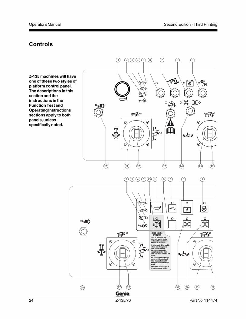
Z-135 machines will haveone of these two styles ofplatform control panel.The descriptions in thissection and theinstructions in theFunction Test andOperating Instructionssections apply to bothpanels, unlessspecifically noted.
Operator's ManualSecond Edition · Third Printing
Part No. 114474 Z-135/70 25
Controls
Operator's Manual Second Edition · Third Printing
26 Z-135/70 Part No. 114474
Controls
Platform Control Panel
1 Horn button
Press the button and the horn will sound.Release the button and the horn will stop.
2 Platform not level indicator light
Level the platform until the light is off. Theswitch will only work in the direction that willlevel the platform.
3 Machine on incline indicator light
Light on indicates all functions have stopped.See the instructions in the OperatingInstructions section.
4 Lower primary boom indicator light
Lower the primary boom until the light is off.
5 Lower / retract secondary boom indicator light
Lower/retract the secondary boom until the lightis off.
6 Used for optional equipment
7 Generator control with indicator light(if equipped)
Move the switch or push the button to turn thegenerator on. Move the switch again or releasethe button to turn the generator off.
8 Emergency/Auxiliary power control with indicatorlight
Use emergency/auxiliary power if the primarypower source (engine) fails.
Move and hold the switch, or push and hold thebutton. Activate the desired function. Theindicator light will be on when emergency/auxiliary power is being used.
9 Glow plug control with indicator light
Move the switch or push the button to activatethe glow plugs.
10 Engine start control with indicator light
Move the switch or push the button and theengine will start. The indicator light will be onwhen the switch is moved or the button ispushed.
11 Engine idle control with indicator light
Move the switch or push the button to selectengine idle setting. The indicator light next tothe current engine idle setting will be on.
12 Not used
13 Power indicator light
Light on indicates the machine is on.
14 Check engine indicator light
Light on indicates an engine fault.
15 Low fuel indicator light
Light on indicates the machine is low on fuel.
16 Fault indicator light
Light on indicates a system fault.
17 Red Emergency Stop button
Push in the red Emergency Stop button to theoff position to stop all functions and turn theengine off. Pull out the red Emergency Stopbutton to the on position to operate themachine.

Operator's ManualSecond Edition · Third Printing
Part No. 114474 Z-135/70 27
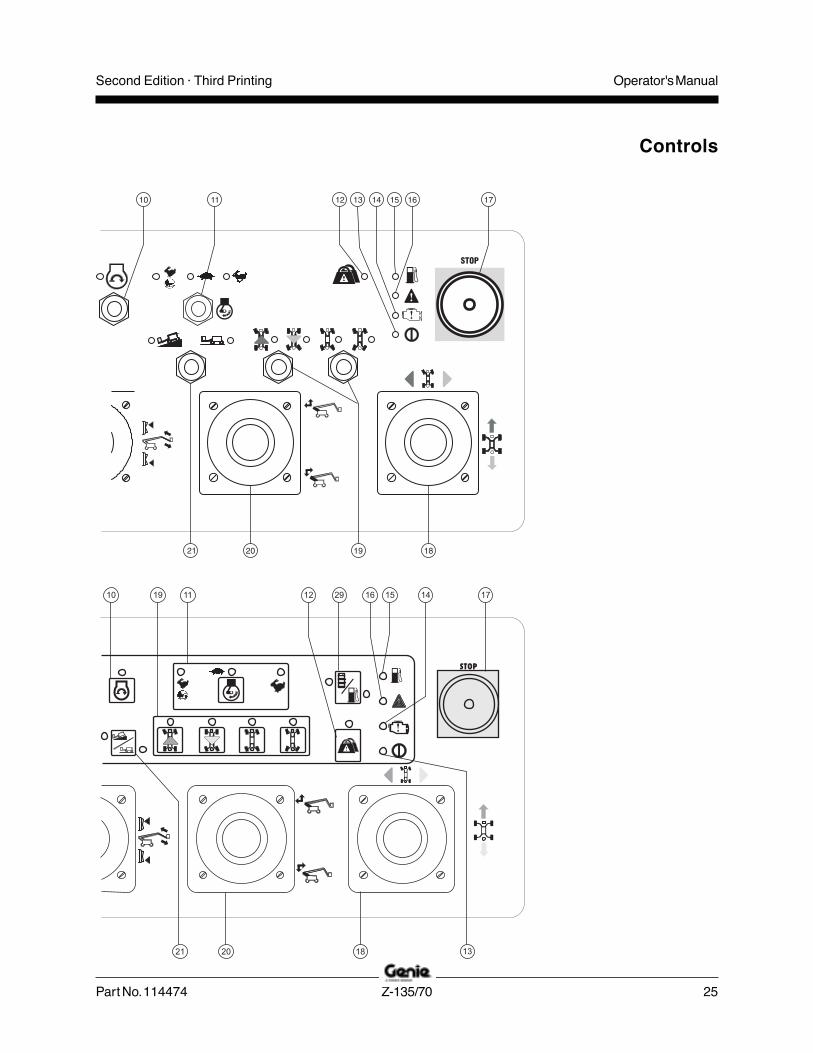
21 Drive control with indicator lights
Move the switch or push the button to choosethe drive setting. The indicator light next to thecurrent setting will be on.
22 Thumb rocker for jib boom extend/retractfunction
Push the top of the rocker switch and the jibboom will retract. Push the bottom of the rockerswitch and the jib boom will extend.
23 Dual axis proportional control handle for jib boomup/down and platform rotate left/right functions
Move the control handle up and the jib boom willraise. Move the control handle down and the jibboom will lower. Move the control handle to theleft and the platform will rotate to the left. Movethe control handle to the right and the platformwill rotate to the right.
24 Axle extend/retract switch with indicator lights
Move the axle select switch to chose an axlesetting. The indicator light will flash while theaxles are extending and stay on when the axlesare fully extended. The indicator light will flashwhile the axles are retracting and stay on whenthe axles are fully retracted.
25 Drive enable control with indicator light
Light on indicates that the primary boom hasmoved past either circle-end wheel and the drivefunction is turned off. To drive, move the driveenable switch or push the drive enable buttonand slowly move the drive/steer control handleoff center.
18 Dual axis proportional control handle for driveand steer functions OR Proportional controlhandle for drive function and thumb rocker forsteer function.
Move the control handle in the directionindicated by the blue arrow on the control paneland the machine will drive forward. Move thecontrol handle in the direction indicated by theyellow arrow and the machine will drivebackwards. Move the control handle in thedirection indicated by the blue triangle and themachine will steer to the left. Move the controlhandle in the direction indicated by the yellowtriangle and the machine will steer to the right.
OR
Move the control handle in the directionindicated by the blue arrow on the control paneland the machine will drive forward. Move thecontrol handle in the direction indicated by theyellow arrow and the machine will drivebackwards. Press the left side of the thumbrocker and the machine will steer to the left.Press the right side of the thumb rocker and themachine will steer to the right.
19 Steer mode control with indicator lights
Move the switch or push the button to choosesteer mode.
The indicator light next to the current steer modewill be on.
20 Single axis proportional control handle forsecondary boom up/extend and down/retractfunction
Move the control handle up and the secondaryboom will raise and then extend. Move thecontrol handle down and the secondary boomwill retract and then lower.
Controls
Operator's Manual Second Edition · Third Printing
28 Z-135/70 Part No. 114474
26 Thumb rocker switch for primary boom extend/retract function
Push the top of the rocker switch and primaryboom will retract. Push the bottom of the rockerswitch and the primary boom will extend.
27 Dual axis proportional control handle for primaryboom up/down and turntable rotate left/rightfunctions
Move the control handle up and the primaryboom will raise. Move the control handle downand the primary boom will lower. Move thecontrol handle to the left and the turntable willrotate to the left. Move the control handle to theright and the turntable will rotate to the right.
28 Platform level switch
Move the switch up and the level of the platformwill raise. Move the switch down and the level ofthe platform will lower.
29 Not used
30 Axle extend button with indicator light
Push the axle extend button to extend the axles.The indicator light will flash while the axles areextending and stay on when the axles are fullyextended.
31 Axle retract button with indicator light
Push the axle retract button to retract the axles.The indicator light will flash while the axles areretracting and stay on when the axles are fullyretracted.
Controls
Operator's ManualSecond Edition · Third Printing
Part No. 114474 Z-135/70 29
Inspections
Do Not Operate Unless:You learn and practice the principles of safemachine operation contained in this operator'smanual.
1 Avoid hazardous situations.
2 Always perform a pre-operationinspection.
Know and understand the pre-operationinspection before going on to the nextsection.3 Always perform function tests prior to use.
4 Inspect the workplace.
5 Only use the machine as it was intended.
Pre-operation InspectionFundamentalsIt is the responsibility of the operator to perform apre-operation inspection and routine maintenance.
The pre-operation inspection is a visual inspectionperformed by the operator prior to each work shift.The inspection is designed to discover if anythingis apparently wrong with a machine before theoperator performs the function tests.
The pre-operation inspection also serves todetermine if routine maintenance procedures arerequired. Only routine maintenance items specifiedin this manual may be performed by the operator.
Refer to the list on the next page and check eachof the items.
If damage or any unauthorized variation fromfactory delivered condition is discovered, themachine must be tagged and removed fromservice.
Repairs to the machine may only be made by aqualified service technician, according to themanufacturer's specifications. After repairs arecompleted, the operator must perform apre-operation inspection again before going on tothe function tests.
Scheduled maintenance inspections shall beperformed by qualified service technicians,according to the manufacturer's specifications andthe requirements listed in the responsibilitiesmanual.

Operator's Manual Second Edition · Third Printing
30 Z-135/70 Part No. 114474
Inspections
Pre-operation InspectionR Be sure that the operator’s, safety and
responsibilities manuals are complete, legibleand in the storage container located in theplatform.
R Be sure that all decals are legible and in place.See Inspections for Decals section.
R Check for engine oil leaks and proper oil level.Add oil if needed. See Maintenance section.
R Check for hydraulic oil leaks and proper oil level.Add oil if needed. See Maintenance section.
R Check for engine coolant leaks and proper levelof coolant. Add coolant if needed. SeeMaintenance section.
R Check for battery fluid leaks and proper fluidlevel. Add distilled water if needed. SeeMaintenance section.
Check the following components or areas fordamage, improperly installed or missing parts andunauthorized modifications:
R Electrical components, wiring andelectrical cables
R Hydraulic hoses, fittings, cylinders andmanifolds
R Fuel and hydraulic tanksR Drive and turntable motors and drive hubsR Boom wear padsR Tires and wheelsR Engine and related componentsR Limit switches and hornR Rotation sensors
R Steer and axle sensorsR Alarms and beacons (if equipped)R Nuts, bolts and other fastenersR Platform entry mid-rail or gate
Check entire machine for:R Cracks in welds or structural componentsR Dents or damage to machineR Excessive rust, corrosion or oxidation
R Be sure that all structural and other criticalcomponents are present and all associatedfasteners and pins are in place and properlytightened.
R After you complete your inspection, be sure thatall compartment covers are in place andlatched.

Operator's ManualSecond Edition · Third Printing
Part No. 114474 Z-135/70 31
Function Test FundamentalsThe function tests are designed to discover anymalfunctions before the machine is put into service.The operator must follow the step-by-stepinstructions to test all machine functions.
A malfunctioning machine must never be used. Ifmalfunctions are discovered, the machine must betagged and removed from service. Repairs to themachine may only be made by a qualified servicetechnician, according to the manufacturer'sspecifications.
After repairs are completed, the operator mustperform a pre-operation inspection and functiontests again before putting the machine into service.
Inspections
1 Select a test area that is firm, level and free ofobstruction.
At the Ground Controls2 Turn the key switch to ground control.
3 Pull out the red Emergency Stop button tothe on position.
Result: The LCD screen will come on anddisplay no error messages. The beacon (ifequipped) should flash.
Note: In cold climates, the LCD readout screen willneed to warm up before the display appears.
4 Start the engine. See Operating Instructionssection.
Test Emergency Stop
5 Push in the red Emergency Stop button to theoff position.
Result: The engine should turn off and nofunctions should operate.
6 Pull out the red Emergency Stop button tothe on position and restart the engine.
Test the Extendable Axles
Note: Start this test with the axles retracted.
7 At the ground controls, push and hold a functionenable/speed select button and push theprimary boom up button.
Result: The primary boom should not raise. Onthe LCD screen, the arrow next to the extendaxle symbol will flash. The boom should notraise unless the axles are extended.
Do Not Operate Unless:You learn and practice the principles of safemachine operation contained in this operator'smanual.
1 Avoid hazardous situations.
2 Always perform a pre-operationinspection.
3 Always perform function tests prior touse.
Know and understand the function testsbefore going on to the next section.4 Inspect the workplace.
5 Only use the machine as it was intended.

Operator's Manual Second Edition · Third Printing
32 Z-135/70 Part No. 114474
Inspections
8 Push and hold a function enable/speed selectbutton and press the secondary boom raise/extend button.
Result: The secondary boom should not raise.On the LCD screen, the arrow next to theextend axle symbol will flash. The secondaryboom should not raise unless the axles areextended.
9 Push and hold a function enable/speed selectbutton and press the primary boom extendbutton.
Result: The primary boom should not extend. Onthe LCD screen, the arrow next to the extendaxle symbol will flash. The primary boom shouldnot extend unless the axles are extended.
10 Push and hold a function enable/speed selectbutton and push the turntable rotate left button.
Result: The turntable should rotate 15° and thenstop. The turntable should not rotate more than15° unless the axles are extended.
11 Push and hold a function enable/speed selectbutton and push the turntable rotate right button.
Result: The turntable should return to center,rotate 15° to the right and then stop. Theturntable should not rotate more than 15° unlessthe axles are extended.
12 Turn the key switch to platform control. At theplatform controls, press and hold the foot switchand move the drive control handle in the forwarddirection.
13 Activate the extend axle function.
Result: The machine should drive and the axlesshould extend. The indicator light will flash whilethe axles are moving and stay on when theaxles are fully extended.
14 Return to the ground controls. Turn the keyswitch to ground control.
15 Push and hold a function enable/speed selectbutton and push the primary boom up buttonand then the primary boom down button.
Result: The primary boom should raise andlower normally.
16 Push and hold a function enable/speed selectbutton and push the secondary boom raise/extend button and then the secondary boomlower/retract button.
Result: The secondary boom should raise andextend and retract and lower normally.
17 Push and hold a function enable/speed selectbutton and push the primary boom extendbutton and then the primary boom retract button.
Result: The primary boom should extend andretract normally.
18 Push and hold a function enable/speed selectbutton and push the turntable rotate left buttonand then the turntable rotate right button.
Result: The turntable should rotate normally.

Operator's ManualSecond Edition · Third Printing
Part No. 114474 Z-135/70 33
Inspections
Test the Machine Functions
19 Do not press and hold a function enable/speedselect button. Attempt to activate each boomand platform function button.
Result: No boom and platform functions shouldoperate.
20 Press and hold a function enable /speed selectbutton and activate each boom and platformfunction button.
Result: All boom and platform functions shouldoperate through a full cycle. The descent alarm(if equipped) should sound while the boom islowering.
Test Emergency/Auxiliary Controls
21 Push in the red Emergency Stop button to theoff position to turn off the engine.
22 Pull out the red Emergency Stop button to theon position.
23 Simultaneously push and hold theemergency/auxiliary power buttonand push each boom function button.
Note: To conserve battery power, testeach function through a partial cycle.
Result: All boom functions should operate.
24 Start the engine.
Test the Tilt Sensor
25 Push one of the LCDscreen control buttons untilTURNTABLE LEVELSENSOR X-DIRECTIONappears.
Result: The LCD screen should display theangle in degrees.
26 Push one of the LCD screen control buttons untilTURNTABLE LEVEL SENSOR Y-DIRECTIONappears.
Result: The LCD screen should display theangle in degrees.
27 Push one of the LCD screen control buttons untilPLATFORM LEVEL SENSOR DEGREESappears.
Result: The LCD screen should display theangle in degrees.

Operator's Manual Second Edition · Third Printing
34 Z-135/70 Part No. 114474
Inspections
Test the Operating Envelope
28 Push one of the LCD screencontrol buttons shown untilPRI BOOM ANGLE TOGRAVITY is displayed.
29 Raise the primary boom and observe the LCDscreen.
Result: The primary boom should raise and theLCD screen should display the primary boomangle in degrees.
30 Lower the primary boom.
31 Simultaneously push the 2LCD screen control buttonsshown to activate statusmode.
32 Push one of the LCD screencontrol buttons shown untilSEC BOOM ANGLE isdisplayed.
33 Push and hold the secondary boom up/extendbutton.
Result: The secondary boom should raise andthe LCD screen should display the secondaryboom angle in degrees.
The secondary boom should raise and thenextend. The secondary boom should not extenduntil it is fully raised.
34 Push and hold the secondary boom down/retractbutton.
Result: The secondary boom should fully retractand then lower. The secondary boom should notlower unless it is fully retracted.
At the Platform ControlsTest Emergency Stop
35 Turn the key switch to platform control.
36 Push in the platform red Emergency Stop buttonto the off position.
Result: The engine should turn off and nofunctions should operate.
37 Pull out the red Emergency Stop button andrestart the engine.
Test the Horn
38 Push the horn button.
Result: The horn should sound.
Test the Tilt Sensor Alarm
39 Push a button or move a switch, such as theengine idle control.
Result: The alarm should sound at the platformcontrols.

Operator's ManualSecond Edition · Third Printing
Part No. 114474 Z-135/70 35
Inspections
Test the Foot Switch
40 Push in the platform red Emergency Stop buttonto the off position.
41 Pull out the red Emergency Stop button tothe on position but do not start the engine.
42 Press down the foot switch and attempt to startthe engine.
Result: The engine should not start.
43 Do not press down the foot switch and restartthe engine.
44 Do not press down the foot switch and test eachmachine function.
Result: No machine functions should operate.
Test Machine Functions
45 Press down the foot switch.
46 Activate each machine function control handle,toggle switch or button.
Result: All functions should operate through afull cycle.
Test the Steering
47 Select square-end (blue arrow) steer.Push the square-end (blue arrow)steer button or move the steer modeswitch.
48 Press down the foot switch.
49 Slowly move the drive/steer control handle inthe direction indicated by the blue triangle onthe control panel OR press the thumb rockerswitch in the direction indicated by the bluetriangle.
Result: The square-end wheels should turn inthe direction that the blue triangles point on thedrive chassis.
50 Slowly move the drive/steer control handle inthe direction indicated by the yellow triangle onthe control panel OR press the thumb rockerswitch in the direction indicated by the yellowtriangle.
Result: The square-end wheels should turn inthe direction that the yellow triangles point onthe drive chassis.
51 Select circle-end (yellow arrow) steer.Push the circle-end (yellow arrow) steerbutton or move the steer mode switch.
52 Press down the foot switch.
53 Slowly move the drive/steer control handle inthe direction indicated by the yellow triangle onthe control panel OR press the thumb rockerswitch in the direction indicated by the yellowtriangle.
Result: The circle-end wheels should turn in thedirection that the blue triangles point on thedrive chassis.

Operator's Manual Second Edition · Third Printing
36 Z-135/70 Part No. 114474
Inspections
54 Slowly move the drive/steer control handle inthe direction indicated by the blue triangle onthe control panel OR press the thumb rockerswitch in the direction indicated by the blue triangle.
Result: The circle-end wheels should turn in thedirection that the yellow triangles point on thedrive chassis.
55 Select crab steer. Push the crab steerbutton or move the steer mode switch.
56 Press down the foot switch.
57 Slowly move the drive/steer control handle inthe direction indicated by the blue triangle onthe control panel OR press the thumb rockerswitch in the direction indicated by the blue triangle.
Result: All wheels should turn in the directionthat the blue triangles point on the drivechassis.
58 Slowly move the drive/steer control handle inthe direction indicated by the yellow triangle onthe control panel OR press the thumb rockerswitch in the direction indicated by the yellowtriangle.
Result: All wheels should turn in the directionthat the yellow triangles point on the drivechassis.
59 Select coordinated steer. Push thecoordinated steer button or move thesteer mode switch.
60 Press down the foot switch.
61 Slowly move the drive/steer control handle in thedirection indicated by the blue triangle on thecontrol panel OR press the thumb rocker switchin the direction indicated by the blue triangle.
Result: The square-end wheels should turn inthe direction that the blue triangles point on thedrive chassis. The circle-end wheels should turnin the direction that the yellow triangles point onthe drive chassis.
62 Slowly move the drive/steer control handle in thedirection indicated by the yellow triangle on thecontrol panel OR press the thumb rocker switchin the direction indicated by the yellow triangle.
Result: The square-end wheels should turn inthe direction that the yellow triangles point onthe drive chassis. The circle-end wheels shouldturn in the direction that the blue triangles pointon the drive chassis.
Operator's ManualSecond Edition · Third Printing
Part No. 114474 Z-135/70 37
Test Drive and Braking
63 Press down the foot switch.
64 Slowly move the drive/steer control handle in thedirection indicated by the blue arrow on thecontrol panel until the machine begins to move,then return the handle to the center position.
Result: The machine should move in thedirection that the blue arrow points on the drivechassis, then come to an abrupt stop.
65 Slowly move the drive/steer control handle in thedirection indicated by the yellow arrow on thecontrol panel until the machine begins to move,then return the handle to the center position.
Result: The machine should move in thedirection that the yellow arrow points on thedrive chassis, then come to an abrupt stop.
Note: The brakes must be able to hold the machineon any slope it is able to climb.
Test the Drive Enable System
66 Press down the foot switch and lower the boomsto the stowed position.
67 Rotate the turntable until the primary boommoves past one of the circle-end tires.
Result: The drive enableindicator light should comeon while the boom isanywhere in the rangeshown.
68 Move the drive/steer control handle off center.
Result: No drive function should operate.
69 Push the drive enable button or move the driveenable switch, and slowly move the drive/steercontrol handle off center.
Result: The drive function should operate.
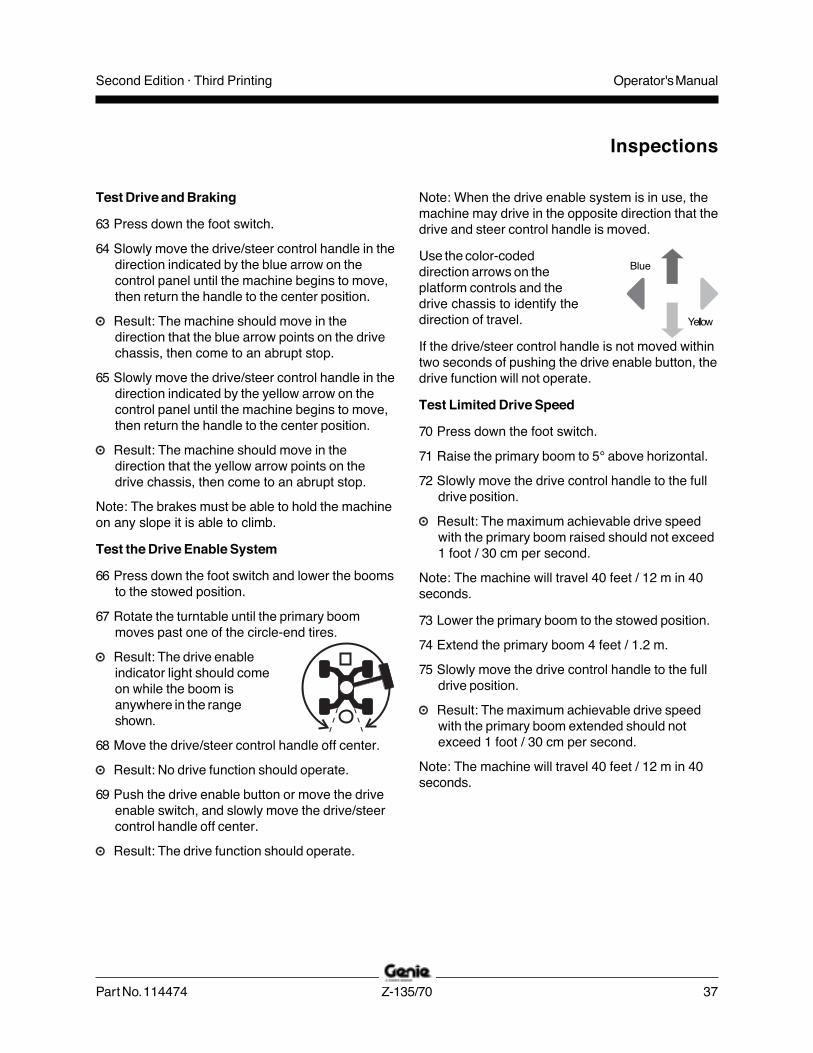
Note: When the drive enable system is in use, themachine may drive in the opposite direction that thedrive and steer control handle is moved.
Use the color-codeddirection arrows on theplatform controls and thedrive chassis to identify thedirection of travel.
If the drive/steer control handle is not moved withintwo seconds of pushing the drive enable button, thedrive function will not operate.
Test Limited Drive Speed
70 Press down the foot switch.
71 Raise the primary boom to 5° above horizontal.
72 Slowly move the drive control handle to the fulldrive position.
Result: The maximum achievable drive speedwith the primary boom raised should not exceed1 foot / 30 cm per second.
Note: The machine will travel 40 feet / 12 m in 40seconds.
73 Lower the primary boom to the stowed position.
74 Extend the primary boom 4 feet / 1.2 m.
75 Slowly move the drive control handle to the fulldrive position.
Result: The maximum achievable drive speedwith the primary boom extended should notexceed 1 foot / 30 cm per second.
Note: The machine will travel 40 feet / 12 m in 40seconds.
Inspections
Blue
Yellow

Operator's Manual Second Edition · Third Printing
38 Z-135/70 Part No. 114474
76 Retract the primary boom to the stowed position.
77 Raise the secondary boom to 5° abovehorizontal.
78 Slowly move the drive control handle to the fulldrive position.
Result: The maximum achievable drive speedwith the secondary boom raised should notexceed 1 foot / 30 cm per second.
Note: The machine will travel 40 feet / 12 m in 40seconds.
79 Lower the secondary boom to the stowedposition.
80 Extend the jib boom 1 foot / 30 cm.
81 Slowly move the drive control handle to the fulldrive position.
Result: The maximum achievable drive speedwith the jib boom extended should not exceed 1foot / 30 cm per second.
If the drive speed with the primary or secondaryboom raised or extended or the jib boom extendedexceeds 1 foot / 30 cm per second, immediatelytag and remove the machine from service.
82 Extend the primary boom 4 feet / 1.2 m.
83 Slowly move the drive control handle to the fulldrive position.
Result: The maximum achievable drive speedwith the jib boom extended and the primaryboom extended should not exceed 6 inches / 15cm per second.
If the drive speed with the jib boom extended andthe primary boom extended exceeds 6 inches /15 cm per second, immediately tag and remove themachine from service.
84 Retract the primary boom and the jib boom.
Test Emergency/Auxiliary Controls
85 Push in the red Emergency Stop button to theoff position to shut off the engine.
86 Pull out the red Emergency Stop button tothe on position.
87 Press down the foot switch.
88 Activate the emergency/auxiliary controls. Moveand hold the switch or push and hold the button.Activate each function control handle, switch orbutton.
Note: To conserve battery power, test eachfunction through a partial cycle.
Result: All boom and steer functions shouldoperate.
Test Aircraft Protection Package (if equipped)
89 Move the gray bumper at the bottom of theplatform 4 inches / 10 cm in any direction.
90 Activate each function control handle or toggleswitch or button.
Result: All boom and steer functions should notoperate.
91 Activate the function override. Move and holdthe switch or push and hold the button.
92 Activate each function control handle or toggleswitch or button.
Result: All boom and steer functions shouldoperate.
Inspections

Operator's ManualSecond Edition · Third Printing
Part No. 114474 Z-135/70 39
Workplace InspectionBe aware of and avoid the following hazardoussituations:
· drop-offs or holes
· bumps, floor obstructions or debris
· sloped surfaces
· unstable or slippery surfaces
· overhead obstructions and high voltageconductors
· hazardous locations
· inadequate surface support to withstand all loadforces imposed by the machine
· wind and weather conditions
· the presence of unauthorized personnel
· other possible unsafe conditions
Do Not Operate Unless:You learn and practice the principles of safemachine operation contained in this operator'smanual.
1 Avoid hazardous situations.
2 Always perform a pre-operationinspection.
3 Always perform function tests prior to use.
4 Inspect the workplace.Know and understand the workplaceinspection before going on to the nextsection.
5 Only use the machine as it was intended.
FundamentalsThe workplace inspection helps the operatordetermine if the workplace is suitable for safemachine operation. It should be performed by theoperator prior to moving the machine to theworkplace.
It is the operator's responsibility to read andremember the workplace hazards, then watch forand avoid them while moving, setting up andoperating the machine.
Inspections

Operator's Manual Second Edition · Third Printing
40 Z-135/70 Part No. 114474
Inspection for Decals with WordsDetermine whether the decals on your machinehave words or symbols. Use the appropriateinspection to verify that all decals are legible and inplace.
Inspections
Shading indicates decal is hidden from view, i.e.under covers.
Part No. Description Quantity
25994 Caution - Component Damage Hazard 1
27204 Arrow - Blue 2
27205 Arrow - Yellow 2
27206 Triangle - Blue 2
27207 Triangle - Yellow 2
28159 Label - Diesel 1
28161 Warning - Crushing Hazard 2
28165 Notice - Foot Switch 1
28174 Label - Power to Platform, 230V 2
28175 Caution - Compartment Access 2
28176 Notice - Missing Manuals 1
28177 Warning - Collision Hazard 2
28181 Warning - No Step or Ride 1
28235 Label - Power to Platform, 115V 2
28236 Warning - Failure To Read . . . 1
31060 Danger - Tip-over Hazard 2
31788 Danger - Battery Safety 1
32998 Notice - Max. Capacity, 600 lbs / 272 kg 1
40434 Label - Lanyard Anchorage 3
44981 Label - Air Line to Platform (option) 2
44986 Notice - Max. Manual Force,90 lbs / 400 N, Australia 1
Part No. Description Quantity
52865 Warning - Annual Inspection 1
65278 Caution - No Step 2
72875 Warning - Pipe Cradle (option) 1
82237 Danger - Electrocution Hazard (option) 4
82314 Danger - Tip-over Hazard 1
82366 Label - Chevron Rykon 1
82410 Warning - Panel Cradle (option) 2
82422 Label - Driving Lights 1
82840 Ground Control Panel 1
82841 Platform Control Panel 1
82862 Danger - Fire Hazard (welder) 1
97576 Notice - Engine Specifications, Deutz 1
97579 Danger - Tip-over Hazard (welder) 1
97602 Warning - Explosion Hazard 1
97603 Notice - Engine Specifications, Perkins 1
97705 Cosmetic - Genie Z-135/70 1
97708 Label - Fuse and Relay Panel Layout 1
97715 Danger/Notice - Tire Specifications 4
97716 Label - Wheel Load 4
97757 Label - Hydraulic Oil Level 1
Decal inspection continues on following page.

Operator's ManualSecond Edition · Third Printing
Part No. 114474 Z-135/70 41
Inspections

Operator's Manual Second Edition · Third Printing
42 Z-135/70 Part No. 114474
Inspection for Decals with WordsDetermine whether the decals on your machinehave words or symbols. Use the appropriateinspection to verify that all decals are legible and inplace.
Inspections
Part No. Description Quantity
97815 Label - Lower Mid-rail 1
97865 Warning - Electrocution Hazard 2
97875 Warning - Weld Lines to Platform 2
97885 Notice - Operating Instructions 2
97887 Notice - Max. Side Force, 150 lbs / 667 N,ANSI & CSA 1
97889 Cosmetic - Z-135 2
97891 Cosmetic - Genie Z-135 1
102188 Notice - Engine Specifications, Cummins 1
114258 Label - No Smoking 1
114389 Danger - General Safety 2
114390 Danger - Electrocution Hazard 2
122043 Instructions - Cummins Specifications 1
128953 Instructions - Deutz Specifications 1
128974 Instructions - Perkins Specifications 1
Shading indicates decal is hidden from view, i.e.under covers.
Decal inspection continued from precedingpage.
Part No. Description Quantity
133163 Label - Function Override(Aircraft Protection Package) 1
133236 Danger - Tip-over Hazard 1
229356 Danger - Tire Specifications, Low Profile 4
230977 Danger - Tire Specifications, Solid Rubber 4
230985 Ground Control Panel 1
230987 Ground Control Panel Key Switch 1
233130 Platform Control Panel 1
1000083 Notice - Start and Controls Battery 1
1000084 Caution - Auxiliary Batteries 1
1000257 Label - Transport Diagram 2

Operator's ManualSecond Edition · Third Printing
Part No. 114474 Z-135/70 43
Inspections

Operator's Manual Second Edition · Third Printing
44 Z-135/70 Part No. 114474
Shading indicates decal is hidden from view, i.e.under covers.
Inspection for Decals withSymbolsDetermine whether the decals on your machinehave words or symbols. Use the appropriateinspection to verify that all decals are legible and inplace.
Inspections
Part No. Description Quantity
27204 Arrow - Blue 2
27205 Arrow - Yellow 2
27206 Triangle - Blue 2
27207 Triangle - Yellow 2
28159 Label - Diesel 1
28174 Label - Power to Platform, 230V 2
28235 Label - Power to Platform, 115V 2
40434 Label - Lanyard Anchorage 3
44981 Label - Air Line to Platform 2
65278 Label - No Step 2
82422 Label - Driving Lights 1
82472 Label - Crushing Hazard 2
82473 Label - Compartment Access 2
82481 Label - Battery Safety 1
82487 Label - Read the Manual 2
82487 Label - Read the Manual, Pipe Cradle 1
82487 Label - Read the Manual, Panel Cradle 1
82546 Notice - Max. Capacity, 272 kg 1
82548 Label - Platform Rotate 2
82602 Label - Max. Side Force, 667 N, ANSI 1
Part No. Description Quantity
82840 Ground Control Panel 1
82841 Platform Control Panel 1
97705 Cosmetic - Genie Z-135/70 1
97716 Label - Wheel Load 4
97757 Label - Hydraulic Oil Level 1
97815 Label - Lower Mid-Rail 1
97889 Cosmetic - Z-135 2
97891 Cosmetic - Genie Z-135 1
114247 Label - Fall Hazard 1
114248 Label - Tip-over Hazard 1
114249 Label - Tire Specifications 4
114251 Label - No Smoking 1
114252 Label - Tip-over Hazard 3
133067 Label - Electrocution Hazard 2
133180 Label - Battery Damage 1
133205 Label - Electrocution/Burn Hazard 2
230985 Ground Control Panel 1
230987 Ground Control Panel Key Switch 1
233130 Platform Control Panel 1
1000054 Label - Drive Enable Patch 1
1000257 Label - Transport Diagram 2

Operator's ManualSecond Edition · Third Printing
Part No. 114474 Z-135/70 45
Inspections

Operator's Manual Second Edition · Third Printing
46 Z-135/70 Part No. 114474
Operating Instructions
Do Not Operate Unless:You learn and practice the principles of safemachine operation contained in this operator'smanual.
1 Avoid hazardous situations.
2 Always perform a pre-operationinspection.
3 Always perform function tests prior to use.
4 Inspect the workplace.
5 Only use the machine as it was intended.
FundamentalsThe Operating Instructions section providesinstructions for each aspect of machine operation.It is the operator's responsibility to follow all thesafety rules and instructions in the operator's,safety and responsibilities manuals.
Using the machine for anything other than liftingpersonnel, along with their tools and materials, toan aerial work site is unsafe and dangerous.
Only trained and authorized personnel should bepermitted to operate a machine. If more than oneoperator is expected to use a machine at differenttimes in the same work shift, they must all bequalified operators and are all expected to follow allsafety rules and instructions in the operator's,safety and responsibilities manuals. That meansevery new operator should perform a pre-operationinspection, function tests, and a workplaceinspection before using the machine.

Operator's ManualSecond Edition · Third Printing
Part No. 114474 Z-135/70 47
Operating Instructions
Starting the Engine1 At the ground controls, turn the key switch to
the desired position.
Deutz models
2 Activate the glow plugs. Push the button ormove the switch. The glow plugs will turn on for30 seconds.
3 Start the engine. Press the buttonor move the switch.
The engine start button can bepressed at any time while the glowplugs are on.
Perkins and Cummins models
2 Activate the glow plugs for 3-5 seconds. Pushand hold the button or move and hold theswitch.
3 Start the engine. Press the button or move andhold the switch.
If the engine fails to start or dies, the restart delaywill disable the start switch for 3 seconds.
If the engine fails to start after 15 seconds ofcranking, determine the cause and repair anymalfunction. Wait 60 seconds before trying to startagain.
In cold conditions, 20°F / -6°C and below, warm theengine for 5 minutes before operating to preventhydraulic system damage.
In extreme cold conditions, 0°F / -18°C and below,machines should be equipped with optional coldstart kits. Attempting to start the engine whentemperatures are below 0°F / -18°C may require theuse of a booster battery.
If the machine is stored for longperiods of time in low temperatures(below 32°F / 0°C) with thesecondary boom raised andextended, the engine may not startdue to a system fault.
To remove the fault, use the emergency controlsand raise the secondary boom up until thesecondary boom begins extending.
Emergency StopPush in either the ground or platform redEmergency Stop button to the off position to stopall functions and turn the engine off.
Repair any function that operates when the redEmergency Stop button is pushed in to the offposition.
Selecting and operating the ground controls willoverride the platform red Emergency Stop button.
Emergency/Auxiliary PowerUse emergency/auxiliary power if the primary powersource (engine) fails.
1 Turn the key switch to ground or platformcontrol.
2 Pull out the red Emergency Stop button to theon position.
3 Press down the foot switch when operating theemergency/auxiliary controls from the platform.
4 Move and hold the switch or pushand hold the button. Activate thedesired function. The indicator lightwill be on when emergency poweris being used.

Operator's Manual Second Edition · Third Printing
48 Z-135/70 Part No. 114474
Operating Instructions
To Position Platform
1 Push and hold a function enable/speed selectbutton.
2 Push the appropriate function button accordingto the markings on the control panel.
Drive, steer and axle functions are not availablefrom the ground controls.
Operation from Platform1 Turn the key switch to platform control.
2 Pull out both ground and platform redEmergency Stop buttons to the on position.
3 Start the engine. Do not press down the footswitch when starting the engine.
To Position Platform
1 Press down the foot switch.
2 Slowly move the appropriate function control
To Extend and Retract Axles1 Turn the key switch to platform control.
2 At the platform controls, press down the footswitch and move the drive control handle ineither direction. Activate the extend axlefunction or the retract axle function. Move theswitch or push the button.
The indicator light will flash while the axles aremoving and stay on when the axles are fullyextended or retracted.
The axles can only be retracted if the primary andsecondary booms are fully lowered and retractedand the platform is between the circle-end wheels.
Operation from Ground1 Turn the key switch to ground control.
2 Pull out the red Emergency Stop button tothe on position.
3 Start the engine.

Operator's ManualSecond Edition · Third Printing
Part No. 114474 Z-135/70 49
Operating Instructions
handle or toggle switch or press the appropriatebutton according to the markings on the controlpanel.
To Steer
1 Press down the foot switch.
2 Select the steer mode. Move theswitch or push the button. Theindicator light next to the current steer mode willbe on.
3 Slowly move the drive/steer control handle in thedirection indicated by the blue or yellowtriangles OR press the thumb rocker switchlocated on top of the drive control handle.
Use the color-coded direction arrows onthe platform controls and the drive chassisto identify the direction the wheels willturn.
To Drive
1 Press down the foot switch.
2 Increase speed: Slowly move the drive/steercontrol handle in the direction indicated by theblue or yellow arrows.
Decrease speed: Slowly move the drive/steercontrol handle toward center.
Stop: Return the drive/steer control handle tocenter or release the foot switch.
Use the color-coded direction arrows on the
platform controls and the drive chassis to identifythe direction the machine will travel.
Machine travel speed is restricted when the boomis raised or extended.
Driving on a slope
Determine the uphill, downhill andside slope ratings for the machineand determine the slope grade.
Maximum slope rating,counterweight uphill (gradeability):45% (24°)
Maximum slope rating,counterweight downhill:30% (17°)
Maximum side slope rating:25% (14°)
Note: Slope rating is subject to ground conditionsand adequate traction. The term gradeability appliesto the counterweight uphill configuration only.
Be sure the boom is below horizontal and theplatform is between the circle-end wheels.
Select the machine on incline drive setting.

Operator's Manual Second Edition · Third Printing
50 Z-135/70 Part No. 114474
Operating Instructions
To determine the slope grade:
Measure the slope with a digital inclinometer ORuse the following procedure.
You will need:
carpenter’s level
straight piece of wood, at least 3 feet / 1 m long
tape measure
Lay the piece of wood on the slope.
At the downhill end, lay the level on the top edge ofthe piece of wood and lift the end until the piece ofwood is level.
While holding the piece of wood level, measure thevertical distance from the bottom of the piece ofwood to the ground.
Divide the tape measure distance (rise) by thelength of the piece of wood (run) and multiply by100.
Example:
Piece of wood = 144 inches (3.6 m)
Run = 144 inches (3.6 m)
Rise = 12 inches (0.3 m)
12 in y 144 in = 0.083 x 100 = 8.3% grade
0.3 m y 3.6 m = 0.083 x 100 = 8.3% grade
If the slope exceeds the maximum uphill, downhillor side slope rating, then the machine must bewinched or transported up or down the slope. Seethe Transport and Lifting section.
Drive EnableLight on indicates that theprimary boom has moved pasteither circle-end wheel and thedrive function is turned off.
To drive, activate the drive enable function andslowly move the drive/steer control handle offcenter. Push the drive enable button or move thedrive enable switch.
If the drive/steer control handle is not moved withintwo seconds of activating the drive enable function,the drive function will not operate. Release andactivate the drive enable function again.
Be aware that the machine may move in theopposite direction that the drive and steer controlsare moved.
Always use the color-coded direction arrows on theplatform controls and the drive chassis to identifythe direction the machine will travel.
When the drive enable light is on, the axles cannotretract.run
rise

Operator's ManualSecond Edition · Third Printing
Part No. 114474 Z-135/70 51
Operating Instructions
Engine Idle Select (rpm)Select the engine idle (rpm) setting. Move theswitch or push the button. The indicator light nextto the current setting will be on.
· Rabbit and foot switch symbol:foot switch activated high idle
· Turtle symbol: low idle
· Rabbit symbol: high idle
Check Engine Light
Light on and engine stopped: Tagthe machine and remove fromservice.
Light on and engine still running:Contact service personnel within 24hours.
Operating Envelope IndicatorLightsThe operating envelope indicator lights will come onto notify the operator that a function has beeninterrupted and/or an action is required by theoperator.
Lower/Retract Secondary Boomindicator light flashing: Lower/retract the secondary boom untilthe indicator light is off.
Lower Primary Boom indicatorlight flashing: Lower the primaryboom until the indicator light isoff.
Machine Not Level indicator lightflashing: The tilt alarm will besounding when this light isflashing. Move the machine to afirm, level surface.
Platform Not Level indicator lightflashing: The tilt alarm will besounding when this light isflashing. The Platform Leveltoggle switch will only work in thedirection that will level theplatform. Level the platform untilthe indicator light is off.
Out of Operational EnvelopeRecoveryIf all functions stop operating, you may haveexceeded the operational envelope. A trainedoperator on the ground will need to lower theplatform from the ground controls. Please see theService Bypass / Recovery Key Switch section inthe service manual.

Operator's Manual Second Edition · Third Printing
52 Z-135/70 Part No. 114474
Generator (if equipped)To operate the generator, press the generatorbutton or move the generator switch. The indicatorlight will come on and the engine will continue torun.
Plug power tools into the power to platform GFCIoutlet.
To turn off the generator, push the generator buttonor move the switch. The indicator light will turn off.
Aircraft Protection Package(if equipped)If the platform bumpers come in contact withaircraft components, the machine will shut downand no functions will operate.
Move the function override toggle switch to eitherside to operate the machine.
After Each Use1 Select a safe parking location—firm level
surface, clear of obstruction and traffic.
2 Retract and lower the boom to the stowedposition.
3 Rotate the turntable so that the boom is betweenthe circle-end wheels.
4 Turn the key switch to the off position andremove the key to secure from unauthorizeduse.
5 Chock the wheels.
Operating Instructions
Operator's ManualSecond Edition · Third Printing
Part No. 114474 Z-135/70 53
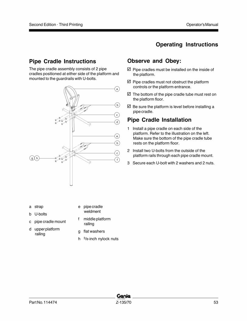
Observe and Obey:Pipe cradles must be installed on the inside ofthe platform.
Pipe cradles must not obstruct the platformcontrols or the platform entrance.
The bottom of the pipe cradle tube must rest onthe platform floor.
Be sure the platform is level before installing apipe cradle.
Pipe Cradle Installation1 Install a pipe cradle on each side of the
platform. Refer to the illustration on the left.Make sure the bottom of the pipe cradle tuberests on the platform floor.
2 Install two U-bolts from the outside of theplatform rails through each pipe cradle mount.
3 Secure each U-bolt with 2 washers and 2 nuts.
The pipe cradle assembly consists of 2 pipecradles positioned at either side of the platform andmounted to the guardrails with U-bolts.
a strap
b U-bolts
c pipe cradle mount
d upper platformrailing
e pipe cradleweldment
f middle platformrailing
g flat washers
h 3/8-inch nylock nuts
Pipe Cradle Instructions
Operating Instructions

Operator's Manual Second Edition · Third Printing
54 Z-135/70 Part No. 114474
Pipe Cradle Operation1 Be sure the pipe cradle assembly and
installation instructions have been followedproperly and that the pipe cradles are secured tothe platform railings.
2 Place the load so that it rests in both pipecradles. The length of the load should beparallel with the length of the platform.
3 Center the load in the pipe cradles.4 Secure the load to each pipe cradle. Pass the
nylon strap over the load. Depress the buckleand slide the strap through. Tighten the strap.
5 Gently push and pull on the load to make surethe pipe cradles and load are secure.
6 Keep the load secured when the machine ismoving. Tip-over hazard. The weight of the pipe cradleassembly and the load in the pipe cradles willreduce the rated platform capacity of themachine and must be factored into the totalplatform load.
Tip-over hazard. The weight of the pipe cradleassembly and the load in the pipe cradles maylimit the maximum number of occupants in theplatform.
Maximum Pipe Cradle Capacity
All models 200 lbs90.7 kg
Pipe Cradle Assembly Weight 21 lbs9.5 kg
Operating Instructions

Operator's ManualSecond Edition · Third Printing
Part No. 114474 Z-135/70 55
Panel Cradle Assembly1 Apply the warning decal to the front of each
panel cradle (if needed).
2 Install rubber bumper 1 in the panel cradle base.See the illustration.
3 Secure the bumper with 2 high profile lock nutsand 2 washers.
Panel Cradle Installation1 Insert the hook piece through the slots in the
panel cradle base.
2 Hook the panel cradle to the bottom platformtube in the desired location.
3 Install rubber bumper 2 through the panel cradlebase and the hook piece. See the illustration.
4 Secure with 2 low profile lock nuts.
5 If the panel cradle is installed at a platform floorsupport tube, insert the U-bolt through the floor,around the tube and into the panel cradle base.
6 Secure the U-bolt with 2 nuts and 2 washers.Proceed to step 9.
7 If the panel cradle is not installed at a platformfloor support tube, use the aluminum tubeprovided.
8 Place the tube between the panel cradle and theplatform floor. Insert the U-bolt through the floor,around the tube and into the panel cradle base.
9 Repeat above for the second set of parts.
Installation of Padding1 Install the 2 pieces of padding on the platform
rails. Position the padding to protect the panelsfrom contact with the platform rails.
Installation of Strap1 Open the clamp and install it around a vertical
platform rail tube.
2 Insert a bolt with a washer through one side ofthe clamp.
3 Install the strap assembly end plate onto thebolt.
4 Insert the bolt through the other side of theclamp.
5 Secure with a washer and a nut. Do not over-tighten. The strap assembly end plate should beable to slide on the platform rail.
Operating Instructions

Operator's Manual Second Edition · Third Printing
56 Z-135/70 Part No. 114474
rubberbumper 1
rubberbumper 2
panelcradlebase
hookpiece
decal
U-boltmounting
slots
padding
clamp
hook
Panel Cradle Operation1 Secure both panel cradles to the platform.
2 Place the load so that it rests in both panelcradles.
3 Center the load on the platform.
4 Secure the load to the platform using the strap.Tighten the strap.
Operating Instructions
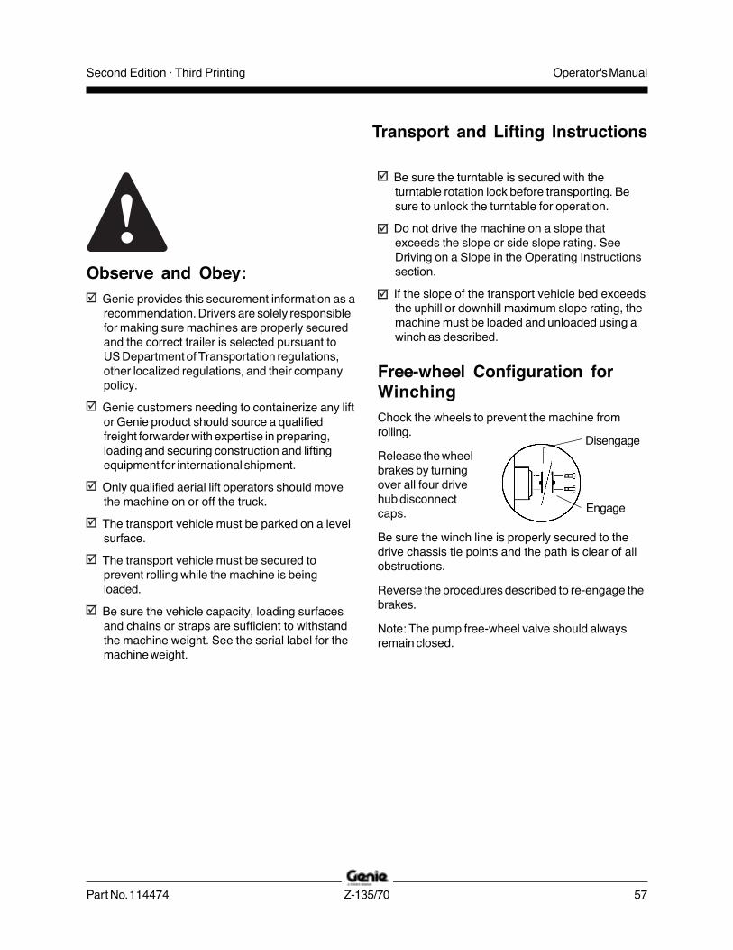
Operator's ManualSecond Edition · Third Printing
Part No. 114474 Z-135/70 57
Transport and Lifting Instructions
Free-wheel Configuration forWinchingChock the wheels to prevent the machine fromrolling.
Release the wheelbrakes by turningover all four drivehub disconnectcaps.
Be sure the winch line is properly secured to thedrive chassis tie points and the path is clear of allobstructions.
Reverse the procedures described to re-engage thebrakes.
Note: The pump free-wheel valve should alwaysremain closed.
Disengage
Engage
Observe and Obey:Genie provides this securement information as arecommendation. Drivers are solely responsiblefor making sure machines are properly securedand the correct trailer is selected pursuant toUS Department of Transportation regulations,other localized regulations, and their companypolicy.
Genie customers needing to containerize any liftor Genie product should source a qualifiedfreight forwarder with expertise in preparing,loading and securing construction and liftingequipment for international shipment.
Only qualified aerial lift operators should movethe machine on or off the truck.
The transport vehicle must be parked on a levelsurface.
The transport vehicle must be secured toprevent rolling while the machine is beingloaded.
Be sure the vehicle capacity, loading surfacesand chains or straps are sufficient to withstandthe machine weight. See the serial label for themachine weight.
Be sure the turntable is secured with theturntable rotation lock before transporting. Besure to unlock the turntable for operation.
Do not drive the machine on a slope thatexceeds the slope or side slope rating. SeeDriving on a Slope in the Operating Instructionssection.
If the slope of the transport vehicle bed exceedsthe uphill or downhill maximum slope rating, themachine must be loaded and unloaded using awinch as described.

Operator's Manual Second Edition · Third Printing
58 Z-135/70 Part No. 114474
Transport and Lifting Instructions
Securing to Truck or Trailer forTransitAlways use the turntable rotation lock pin each timethe machine is transported.
Turn the key switch to the off position and removethe key before transporting.
Inspect the entire machine for loose or unsecureditems.
Securing the Chassis
Use chains of ample load capacity.
Use a minimum of 6 chains.
Adjust the rigging to prevent damage to the chains.
Securing the Platform
Place a block under the platform rotator. Do notallow the block to contact the platform cylinder.
Secure the platform with a nylon strap placedthrough the lower platform support. Do not useexcessive downward force when securing the boomsection.
42 ft 5 in12.97 m
10 ft 10 in3.3 m
4 ft 4 in1.31 m
19 ft 2 in5.84 m
25 ft 1 in7.65 m
14 ft4.25 m
10 ft3.07 m
Secondary boom width:26 in66 cm
Jib boom width:16 in
41 cm
Truck Bed

Operator's ManualSecond Edition · Third Printing
Part No. 114474 Z-135/70 59
Transport and Lifting Instructions
Observe and Obey:Only qualified riggers should rig and lift themachine.
Be sure the crane capacity, loading surfacesand straps or lines are sufficient to withstandthe machine weight. See the serial label for themachine weight.
Lifting InstructionsFully lower and retract the primary and secondaryboom. Fully lower and retract the jib boom. Removeall loose items on the machine.
Determine the center of gravity of your machineusing the picture on this page.
Attach the rigging only to the designated liftingpoints on the machine. There are four lifting pointson the chassis.
Adjust the rigging to prevent damage to themachine and to keep the machine level.
56 in1.4 m
59.5 in1.5 m

Operator's Manual Second Edition · Third Printing
60 Z-135/70 Part No. 114474
Maintenance
Observe and Obey:Only routine maintenance items specified in thismanual shall be performed by the operator.
Scheduled maintenance inspections shall becompleted by qualified service technicians,according to the manufacturer's specificationsand the requirements specified in theresponsibilities manual.
Use only Genie approved replacement parts.
Maintenance Symbols Legend
The following symbols have been used in thismanual to help communicate the intent of theinstructions. When one or more of the symbolsappear at the beginning of a maintenanceprocedure, it conveys the meaning below.
Indicates that tools will be required toperform this procedure.
Indicates that new parts will be required toperform this procedure.
Indicates that a cold engine is requiredbefore performing this procedure.
Check the Engine Oil Level
Maintaining the proper engine oil level is essentialto good engine performance and service life.Operating the machine with an improper oil levelcan damage engine components.
Note: Check the oil level with the engine off.
1 Check the engine oil dipstick. Add oil asneeded.
Perkins 1104C-44 and 804D-33T Engine
Oil type 15W-40
Oil type - cold conditions, 1104C 10W-30
Oil type - cold conditions, 804D 5W-40
Deutz BF4L2011 and TD2011L04i Engine
Oil type 15W-40
Oil type - cold conditions 5W-30
Cummins B4.5C80 and B3.3C80 Engine
Oil type 15W-40
Oil type - cold conditions 10W-30

Operator's ManualSecond Edition · Third Printing
Part No. 114474 Z-135/70 61
Maintenance
Check the Hydraulic Oil Level
Maintaining the hydraulic oil at the proper level isessential to machine operation. Improper hydraulicoil levels can damage hydraulic components. Dailychecks allow the inspector to identify changes inthe oil level that might indicate the presence ofhydraulic system problems.
1 Be sure that the engine is off and the boom is inthe stowed position.
2 Visually inspect the sight gauge located on theside of the hydraulic oil tank.
Result: The hydraulic oil level should bebetween the two marks on the decal next to thesight gauge. Add oil as needed.
Hydraulic oil specifications
Hydraulic oil type Chevron Rykon®Premium MV equivalent
Check the Batteries
Proper battery condition is essential to good engineperformance and operational safety. Improper fluidlevels or damaged cables and connections canresult in engine component damage and hazardousconditions.
Electrocution hazard. Contact with hot or livecircuits may result in death or serious injury.Remove all rings, watches and other jewelry.
Bodily injury hazard. Batteries contain acid.Avoid spilling or contacting battery acid.Neutralize battery acid spills with baking sodaand water.
1 Put on protective clothing and eye wear.
2 Be sure that the battery cable connections aretight and free of corrosion.
3 Be sure that the battery hold-down bar is inplace and secure.
4 Remove the battery vent caps.
5 Check the battery acid level. If needed,replenish with distilled water to the bottom of thebattery fill tube. Do not overfill.
6 Install the vent caps.
Note: Adding terminal protectors and a corrosionpreventative sealant will help eliminate corrosion onthe battery terminals and cables.
Maximum oil level
Minimum oil level

Operator's Manual Second Edition · Third Printing
62 Z-135/70 Part No. 114474
Maintenance
Check the Engine Coolant Level- Liquid Cooled Models
Maintaining the engine coolant at the proper level isessential to engine service life. An improper coolantlevel will affect the engine's cooling capability anddamage engine components. Daily checks willallow the inspector to identify changes in coolantlevel that might indicate cooling system problems.
1 Check the fluid level in the coolant recoverytank. Add fluid as needed.
Result: The fluid level should be in theNORMAL range.
Bodily injury hazard. Fluids in the radiator areunder pressure and extremely hot. Use cautionwhen removing cap and adding fluids.
Scheduled MaintenanceMaintenance performed quarterly, annually andevery two years must be completed by a persontrained and qualified to perform maintenance on thismachine according to the procedures found in theservice manual for this machine.
Machines that have been out of service for morethan three months must receive the quarterlyinspection before they are put back into service.

Operator's ManualSecond Edition · Third Printing
Part No. 114474 Z-135/70 63
Specifications
Z-135/70
Height, working maximum 141 ft 42.9 m
Height, platform maximum 135 ft 41.1 m
Height, stowed maximum 10 ft 1 in 3.1 m
Horizontal reach, maximum 69 ft 9 in 21.3 m
Width, axles retracted 8 ft 1 in 2.5 m
Width, axles extended 12 ft 11 in 3.9 m
Length, stowed 42 ft 5 in 12.9 m
Maximum load capacity 600 lbs 272 kg
Maximum wind speed 28 mph 12.5 m/s
Wheelbase, axles extended 13 ft 6 in 4.1 m
Wheelbase, axles retracted 15 ft 6 in 4.7 m
Ground clearance 20 in 51 cm
Turning radius, axles extendedinside 7 ft 6 in 2.3 moutside 18 ft 6 in 5.6 m
Turning radius, axles retractedinside 18 ft 1 in 5.5 moutside 25 ft 6 in 7.8 m
Turntable rotation 360° continuous
Turntable tailswing,secondary boom lowered 14 ft 4.3 m
Turntable tailswing,secondary boom raised 2 ft 7 in 78 cm
Drive speed, stowed 3.0 mph 4.8 km/h40 ft/9.1 sec 12.2 m/9.1 sec
Drive speed, 0.7 mph 1.1 km/hraised or extended 40 ft/40 sec 12.2 m/40 sec
Drive speed, 0.4 mph 0.6 km/hraised and extended 40 ft/68 sec 12.2 m/68 sec
Controls 12V DC proportional
Platform dimensions, 6 foot 72 in x 30 in(length x width) 1.8 m x 76 cm
Platform dimensions, 8 foot 96 in x 36 in(length x width) 2.4 m x 91 cm Continuous improvement of our products is a Genie
policy. Product specifications are subject to changewithout notice or obligation.
Platform leveling self-leveling
Platform rotation 160°
AC outlet in platform standard
Hydraulic pressure, maximum 2900 psi(boom functions) 203 bar
Hydraulic pressure, maximum 3100 psi(auxiliary power unit) 218 bar
System voltage 12V
Tire size 18-22.5, 18 ply FFor 445D50/710, 18 ply FF
Fuel tank capacity 40 gallons 151 liters
Weight See Serial Label(Machine weights vary with option configurations)
Maximum slope rating, stowed position
Counterweight uphill 45% (24°)
Counterweight downhill 30% (17°)
Side slope 25% (14°)
Note: Slope rating is subject to ground conditions andadequate traction.
Floor loading information
Tire load, maximum 25,000 lbs 11,336 kg
Tire contact pressure 130 psi 9.14 kg/cm2
896 kPa
Occupied floor pressure 204 psf 996 kg/m2
9.76 kPa
Note: Floor loading information is approximate anddoes not incorporate different option configurations. Itshould be used only with adequate safety factors.

Operator's Manual Second Edition · Third Printing
64 Z-135/70 Part No. 114474
Specifications
Z-135/70 Range of Motion


![133571 53 GR [ANSICSA] - Genieliftmanuals.gogenielift.com/Operators/English/133571.pdfFifth Edition † Third Printing Operator's Manual Introduction Part No. 133571 GR-12 † GR-15](https://static.fdocuments.us/doc/165x107/5f0fade57e708231d4455a07/133571-53-gr-ansicsa-fifth-edition-a-third-printing-operators-manual-introduction.jpg)