OPERATORS MANUAL - westerbeke.coms manual/48009 3.0 bpmg-bcg... · NFPA (National Fire Protection...
52
OPERATORS MANUAL Single Phase I 60Hz and 50Hz · GASOL:IN.E G.ENERATORS 3 OBP . MG. Fresh·Waterand • ·•· · · · .. Ra·w Water Cooled Models Fresh·Water Cooled Model . PUBLICATION NO. 48009 ·]. REVISION 7 APRIL2018 • WESTERB£KE CORPORATION• MYLES STANDISH INDUSTRIAL PARK JI 150 JOHN HANCOCK ROAD, TAUNTON, MA 02780-7310 U.S.A. . ""!f:Td..., .,4;,.,};J Member National lltlarinc Manufacturers Associati<m ··--·
Transcript of OPERATORS MANUAL - westerbeke.coms manual/48009 3.0 bpmg-bcg... · NFPA (National Fire Protection...

OPERATORS MANUAL Single Phase I 60Hz and 50Hz
· GASOL:IN.E G.ENERATORS 3 OBP. MG. Fresh·Waterand
• ·•· · · · .. Ra·w Water Cooled Models
Fresh·Water Cooled Model
. PUBLICATION NO. 48009 ·]. REVISION 7
APRIL2018
J'~'WESTERBEKE • WESTERB£KE CORPORATION• MYLES STANDISH INDUSTRIAL PARK JI 150 JOHN HANCOCK ROAD, TAUNTON, MA 02780-7310 U.S.A.
. ""!f:Td..., .,4;,.,};J Member National lltlarinc Manufacturers Associati<m
··--·

CALIFORNIA PROPOSITION 65 WARNING
Marine diesel and gBSC)line engine exhaust and some of its constituents are known to the State of California
to cause cancer, birth defects, and other reproductive harm.
AwARNING: Exhaust gasses contain Carbon Monoxide, an odorless and colorless gas. Carbon Monoxide is poisonous and can cause unconsciousness and death. Symptoms of Carbon Monoxide exposure can Include: •Dizziness •Nausea •Headache
. • Throbbing in Temples ·•Muscular Twitching •Vomiting
• Weakness and Sleepiness •Inability to Think Coherently
IF YOU OR ANYONE ELSE EXPERIENCE ANY OF THESE SYMPTOMS, ·, GET OUT INTO THE FRESH AIR IMMEDIATELY. If symptoms persist,
seek medical attention. Shut down the unit and do not restart until It has been inspected and repaired.
This WARNING DECAL Is provided by WES'fERBEKE and should be fixed to a bulkhead neat iour engine or generator.
WE81ERBEKE·alsa recommends installing CARBON MONOXIDE DETECTORS in the /Milg/sleeplng quartets of your vessel •
. Tlley are lnexpenstve and easily · obtainable at your local marine store.

Gasoline with an ETHANOL content higher than 10°/o (E10) is not allowed
· and may void warranty.
TM
Engines & Generators

page

SAFETY INSTRUCTIONS 'INTRODUCTION Read this safety manual carefully. Most accidents are caused by failure to follow fundamental rules and precautions. Know when dangerous conditions exist and take the necessary precautions to protect yourself, your personnel, and your machin"J_. . __ .. . _ _ _ _
As the.dwner or ope(&loF, always 00.selW the following.Bafety rules and advisories provided for your convenience. This safety lnfonnation is in alignment witfl tbe'lftTlerican Boat and Yacht Council ( ABYC) · stanilalUB; however, satef;y riSl(s are not limited to the infomlation in the followfng pages. The responsibility for the ldentiticatioo of potential and 8(iual risks for compliance with all safely ~Hes, mfiitdemit1ce·ai:tivilies. and other condilions belong exclushlely to theQWf18ffoperatm:
, PREVENT ELECTRIC SHOCK
A WARNING: Do not.taudl Ai: electrical canDet:tions while eagiae is m11aiag, or when connBctrid to sho,.,, power. Lethal voltage is jJresellt at th~ connections!
111 Do not operate this machinery without electrical enclosures and covers in place.
B Shut off electrical ,power before accessing electrical equipment
• Use insulated mats whenever working on electrical equipment
• Make sure your clothing and skin are dry, not damp (particularly shoes) when handling electrical equipment
• Remove wristwatch and all jewelry when working on electrical equipment
PREVENT BURNS- HOT ENGINE
A WARNING: Do not·tout:h hot engine parts or exhaust system components. A running engine gets very hot!
• Monitor engine antifreeze coolant level at the plastic coolant recovery tank and periodically at the filler cap location on the water jacketed exhaust manifold, but only when the engine is COLD.
A WARNING: Steam can cause injury or death!
Ill In case of an engine overheat, allow the engine to cool before touching the engine or checking the coolant.
PREVENT BURNS - FIRE
I A WAlllllNG: Flm IBll """""*' ar tlmllll
• Prevent :Bash fires. Do not smoke or pennit flames or sparks to occur near the carburetor, fuel line, filter, fuel pump, or other potential sources of spilled fuel or fuel vapors. Use a suitable container to catch all fuel when removing the fuel line, carburetor, or fuel filters.
• Do not operate with the air cleaner/silencer removeid. Backfire can cause severe injury or death.
• Do not smoke or pennit flames or sparks to occur near the fuel system. Keep the compartment and the engine/generator clean and free of debris to miniurire the chances of fire'. Wipe up all spilled fuel and engine oil.
II Be aware - diesel fuel will burn.
PREVENT BURNS - EXPLOSION
. A WARNING: Explosions from fas/ rapotS t:an tJllllSB
injury or death!
• •Follow re-fueling safety instructi.OllS. Keep the vessel's hatches clOsed when fueling. Open and ventilate cabin after fueling. Check below for fumes/vapor before running the blower. Run the blow~ for four minutes before starting your engine. · ·
ii All fuel vapors are highly explosive. Use extreme care when handling and storing fuels. Store fuel in a wellventilated area away from spark-producing equipment· and out of the reach of children. -
• Do not fill the fuel tank(s) while the engine is running. .. '· • Shut off the fuel service valve at the engine when servicing the fu~ system. Tuke care in catc~ any fuel that might spill. DO Nor allow any smolmig, open :flames, or other sources of fire near the fuel system or engine when servicing. Ensure proper ventilation exists when servicing the fuel system.
1111 Do not alter or modify the fuel system. Ill Be sure all fuel supplies have a positive shutoff valve. II Be certain fuel line fittings are adequately tightened and
free of leaks. II Make sure a fire extinguisher is installed nearby and is
properly maintained. Be familiar with its proper use. Extinguishers rated ABC by the NFPA are appropriate for all applications encountered in Uiis environment.
Engines & Generators
i

SAFETY INSTRUCTIONS ACCIDENTAL STARTING
A WARNING: Accidental starting can cause injury or death!
• Disconnect the battery cables before servicing the engine/ generator. Remove the negative lead first and reconnect it last.
• Make certain all personnel are clear of the engine before starting.
• Make certain all covers, guards, and hatches are reinstalled before starting the engine.
BATTERY EXPLOSION
A WARNING: Battery explosion can cause injury or death!
• Do not smoke or allow an open flame near the battery being serviced. Lead acid batteries emit hydrogen, a highly explosive gas, which can be ignited by electrical arcing or by lit tobacco products. Shut off all electrical equipment in the vicinity to prevent electrical arcing during servicing.
• Never connect the negative(-) battery cable to the positive(+) connection terminal of the starter solenoid. Do not test the battery condition by shorting the terminals together. Sparks could ignite battery gases or fuel vapors. Ventilate any compartment containing batteries to prevent accumulation of explosive gases. To avoid sparks, do not disturb the battery charger connections while the battery is being charged.
• Avoid contacting the terminals with tools, etc., to prevent bums or sparks that could cause an explosion. Remove wristwatch, rings, and any other jewelry before handling the battery.
• Always tum the battery charger off before disconnecting the battery connections. Remove the negative lead first and reconnect it last when disconnecting the battery.
BATTERY ACID
A WARNING: Sulfuric acid in batteries can cause severe injury or death!
• When servicing the battery or checking the electrolyte level, wear rubber gloves, a rubber apron, and eye protection. Batteries contain sulfuric acid which is destructive. If it comes in contact with your skin, wash it off at once with water. Acid may splash on the skin or into the eyes inadvertently when removing electrolyte caps.
TOXIC EXHAUST GASES
A WARNING: Carbon monoxide (CO} is a deadly gas!
• Ensure that the exhaust system is adequate to expel gases discharged from the engine. Check the exhaust system regularly for leaks and make sure the exhaust manifolds are securely attached and no warping exists. Pay close attention to the manifold, water injection elbow, and exhaust pipe nipple.
• Be sure the unit and its surroundings are well ventilated.
• In addition to routine inspection of the exhaust system, install a carbon monoxide detector. Consult your boat builder or dealer for installation of approved detectors.
• For additional information refer to ABYC T-22 (educational information on Carbon Monoxide).
A WARNING: Carbon monoxide (CO} is an invisible odorless gas. Inhalation produces flu-like symptoms, nausea or death!
• Do not use copper tubing in diesel exhaust systems. Diesel fumes can rapidly destroy copper tubing in exhaust systems. Exhaust sulfur causes rapid deterioration of copper tubing resulting in exhaust/water leakage.
• Do not install exhaust outlet where exhaust can be drawn through portholes, vents, or air conditioners. If the engine exhaust discharge outlet is near the waterline, water could enter the exhaust discharge outlet and close or restrict the flow of exhaust. Avoid overloading the craft.
• Although diesel engine exhaust gases are not as toxic as exhaust fumes from gasoline engines, carbon monoxide gas is present in diesel exhaust fumes. Some of the symptoms or signs of carbon monoxide inhalation or poisoning are:
Vomiting Muscular twitching
Dizziness Intense headache
Throbbing in temples Weakness and sleepiness
AVOID MOVING PARTS
A WARNING: Rotating parts can cause injury or death!
• Do not service the engine while it is running. If a situation arises in which it is absolutely necessary to make operating adjustments, use extreme care to avoid touching moving parts and hot exhaust system components.
Engines & Generators
ii

SAFETY INSTRUCTIONS • Do not wear loose clothing or jewelry when servicing
equipment; tie back long hair and avoid wearing loose jackets, shirts, sleeves, rings, necklaces or bracelets that could be caught in moving parts.
• Make sure all attaching hardware is properly tightened. Keep protective shields and guards in their respective places at all times.
• Do not check fluid levels or the drive belt's tension while the engine is operating.
• Stay clear of the drive shaft and the transmission coupling when the engine is running; hair and clothing can easily be caught in these rotating parts.
HAZARDOUS NOISE
A WAR~ING: High noise levels can cause hearing loss!
• Never operate an engine without its muffler installed. • Do not run an engine with the air intake (silencer)
removed. • Do not run engines for long periods with their enclosures
open.
A WARNING: Do not work on machinery when you are mentally or physically incapacitated by fatigue!
OPERATORS MANUAL Many of the preceding safety tips and warnings are repeated in your Operators Manual along with other cautions and notes to highlight critical information. Read your manual carefully, maintain your equipment, and follow all safety procedures.
GASOLINE ENGINE AND GENERATOR INSTALLATIONS Preparations to install a gasoline engine or generator should begin with a thorough examination of the American Boat and Yacht Council's (ABYC) standards. These standards are from a combination of sources including the USCG and the NFPA. Sections of the ABYC standards of particular interest are: H-2 Ventilation H-24 Gasoline Fuel Systems P-1 Exhaust Systems P-4 Inboard Engines E-9 DC Electrical Systems All installations must comply with the Federal Code of Regulations (FCR).
ABYC, NFPA AND USCG PUBLICATIONS FOR INSTALLING DIESEL ENGINES Read the following ABYC, NFPA and USCG publications for safety codes and standards. Follow their recommendations when installing your engine. ABYC (American Boat and Yacht Council) "Safety Standards for Small Craft" Order from:
ABYC 3069 Solomon's Island Rd. Edgewater, MD 21037
NFPA (National Fire Protection Association) "Fire Protection Standard for Motor Craft'' Order from:
NFPA 11 Tracy Drive Avon Industrial Park Avon, MA 02322
USCG (United States Coast Guard) "USCG 33CFR183" Order from:
U.S. Government Printing Office Washington, D.C. 20404
Engines & Generators
iii

INSTALLATION
When installing WESTERBEKE engines and generators it is important that strict attention be paid to the following information:
CODES AND REGULATIONS Strict federal regulations, ABYC guidelines, and safety codes must be complied with when installing engines and generators in a marine environment.
SIPHON-BREAK For installations where the exhaust manifold/water injected.exhaust elbow is close to or will be below the vessel's waterline, provisions must be made to install a siphonbreak in the raw water supply hose to the exhaust elbow. This hose must be looped a minimum of 20" above the vessel's waterline. Failure to use a siphon-break when the exhaust manifold/water injected exhaust elbow is near or below the loaded water line of the vessel will result in raw water damage to the engine and possible flooding of the vessel. If you have any doubt about the position of the water-injected exhaust elbow relative to the vessel's waterline under the vessel's various operating conditions, install a siphon-break. NOTE: A siphon-break requires periodic inspection and cleaning to ensure proper operation. Failure to properly maintain a siphon-break can result in catastrophic engine damage. Consult the siphon-break manufacturer for proper maintenance.
EXHAUST SYSTEM The exhaust system's hose MUST be ce1tified for marine use. Conugated Mmine Exhaust Hose is reconunended. The use of this type of hose allows for extreme bends and turns without the need of additiinal fitting and clamps to accomplish these bends and turns .In this regard, a single length of corrugated exhaust hose can be used. The system MUST be designed to prevent the entry of water into the exhaust system under any sea conditions and at any angle of vessels heal.
A detailed Marine Installation Manual covering gasoline and diesel engines and generators is supplied with every unit sold. This manual .is also available in pdf format on our website to download Website: www.westerbeke.com
Engines & Generators
iv
AVAILABLE FROM YOUR WESTERBEKE DEALER
SIPHON-BREAK WITH STAINLESS LOOP FOR 1" HOSE PART NO. 044010

TABLE OF CONTENTS
Parts Identification BCG ................................................. 2
Parts Identification BPMG .............................................. 3
Introduction ...................................................................... .4
Installation ........................................................................ 6 Rigging and Lifting ...................................................... 6 Location and Mounting ................................................ 6 Raw Water Discharge ................................................... 7 Raw Water Supply Hose .............................................. 7
Fuel, Engine Oil and Engine Coolant.. .......................... 8 Fresh Water Cooled Models ......................................... 8
Control Panels • Starting/Stopping Procedure ........... 9 Remote Panel ............................................................... 9
Preparations for Initial Start-Up ................................. 10 Pre-start Inspection ..................................................... 10 Fresh Water Cooled Models ....................................... 10
Safety Shutdown Switches ........................................... 11 Overspeed Switch ....................................................... 11 Main Circuit Breaker .................................................. 11 Fuses ........................................................................... 11 Exhaust Temperature Switch ...................................... 11 Low Oil Switch .......................................................... 11 High Exhaust Temperature Switch ............................. 11
Maintenance Schedule .................................................. 12 Engine Lubricating Oil ................................................... 14
Changing the Oil Filter .............................................. 14
Fuel System ..................................................................... 15 Changing the Fuel Filter ............................................ 15 Fuel Pump ................................................................. 15
Cooling System ............................................................... 16 Water Pump ................................................................ 16 Water Intake Strainer .................................................. 16 Changing the Impeller ................................................ 16
Cooling System [Fresh Water Cooled Modelst ............. .17 Raw Water Pumps [Overhaul) ........................................ .18
Re-Assembly .............................................................. 19
Cooling System ............................................................... 20 Thermostat. ................................................................. 21 Heat Exchanger ......................................................... .21
Carburetor ........................................................................ 22
DC Circuit/Battery .......................................................... 23
Shore Power Transfer Switch ....................................... 23
Electronic Governor ....................................................... 24
Engine Adjustments ....................................................... 25 Adjusting the Drive Belt ............................................ 25 Oil Pressure ................................................................ 25 Engine Compression Test ........................................... 26 Water Pump Belt ........................................................ 26 Ignition Timing ........................................................... 26 Spark Plug .................................................................. 27 Thermostat [Raw Water Cooled Model] .................... 27 Valve Clearance .......................................................... 28 Replacing the Timing Belt ......................................... 29
Troubleshooting Guide ................................................... 30 Wiring Diagram ............................................................... 32 Generator Information ................................................... 33 BCG/BPMG Troubleshooting ......................................... .34 BCG Internal Wiring Diagram ....................................... 35 lay-Up and Recommissioning ...................................... 36 Flushing The Cooling System ....................................... 37 Generator Specifications ............................................. .38 Metric Conversions ........................................................ 39 Suggested Spare Parts ................................................. ~40
*Models manufactured with heat exchangers for cooling with fresh water/coolant or raw water cooled models that have been converted to . fresh cooling via WESTERBEKE'S FRESH WATER COOLING KIT.
Engines & Generators
1

EXHAUST". HOSE CONNECTION'
3.0KW BC1G GENERATOR . .
PARTS 10-ENTIFICATION IGNITION CONTROL MODULE
1_DA FU$J
GROUNDk°fRAP
AC CIRCUIT BREAKER .
ENGINE SERIAL · _Nl,IJA~ER
RIGHT SIDE
Engines & Generators
2
LEFT SIDE
...--ACTUATOR
COOLANT TEMPERATURE SWITCH
· CO~LANT PRESSURE CAP
SERVICE SIDE DRIP PAN

1IGNITION CONTROL ,MODULE
GENERATOR TECHNICAL DATA LABEL
IGNITION COi
EXHAUST
FUEL PUMP
3.0 KW BPMG GENERATOR PARTS IDENTIFICATION
IGNITION COIL
ENGINE SERIAL NUMBER
MAGNETIC PICK-UP
SERVICE SIDE
DRIP·PAN
FRESHWATER (COOLANT) MODEL
10AFUSE
ENGINE SERIAL\;:
, HOUR·· ~ METER'~
NUMBER \
,....., ...... --t.._ GENERATOR
IPHONBREAK •CONNECTION
COOLANT PUMP
ACTUATOR
LEFT SIDE
ARBURETOR
Engin~t;; & Generators
3
WATER INJECTED EXHAUST ELBOW
ZINC ANODE
SERVICE SIDE.·
RAW WATER PUMP
INTRODUCTION These high performance marine engines are products of WESTERBEKE's long years of experience and advanced technology. We take great pride in the superior durability and dependable performance of our_ engines and generators. Thank you for selecting WESTERBEKE. In order to get the full use and benefit from your generator, it is important that you operate and maintain it correctly. Th.is manual is designed to help you do this. Please read this manual carefully and observe all the safety precautions throughout. Should your engine require servicing, contact your nearest WESTERBEKE dealer for assistance.
This is your operators manual. A parts catalog is also provided and a technical manual_ is available from your WESTERBEKE dealer. If you are planning to install this equipment, contact your WESTERBEKE dealer for WESTERBEKE' S installation manual.
WARRANTY PROCEDURES Your WESTERBEKE Warranty is included in a separate folder. If, after 60 days of submitting the Warranty Registry form you have not received a customer identification card registering your warranty, please contact the factory in writing with model information, including the unit's serial number and commission date.
Customer Identification Card
lw/WESTERBEKE Customer Identification
MR. WESTERBEKE OWNER
MAIN STREET HOMETOWN, USA
Model
Expires
PRODUCT SOFTWARE
Ser.#
Product software, (technical data, parts lists, manuals, brochures and catalogs), provided from sources other than WESTERBEKE are not within WESTERBEKE's control. WESTERBEKE CANNOT BE RESPONSIBLE FOR THE CONTENT OF SUCH SOFTWARE, MAKES NO WARRANTIES OR REPRESENTATIONS WITH RESPECT THERETO, INCLUDING ACCURACY, TIMEUNESS OR COMPLETENESS THEREOF AND WILL IN NO EVENT BE UABLE FOR ANY TYPE OF DAMAGE OR INJURY INCURRED IN CONNECTION WITH OR ARISING OUT OF THE FURNISHING OR USE OF SUCH SOFTWARE.
WESTERBEKE customers should keep in mind the time span between printings of WESTERBEKE product software and the unavoidable existence of earlier WESTERBEKE product software. The product software provided with WESTERBEKE products, whether from WESTERBEKE or other suppliers, must not and cannot be relied upon exclusively as the definitive authority on the respective product.
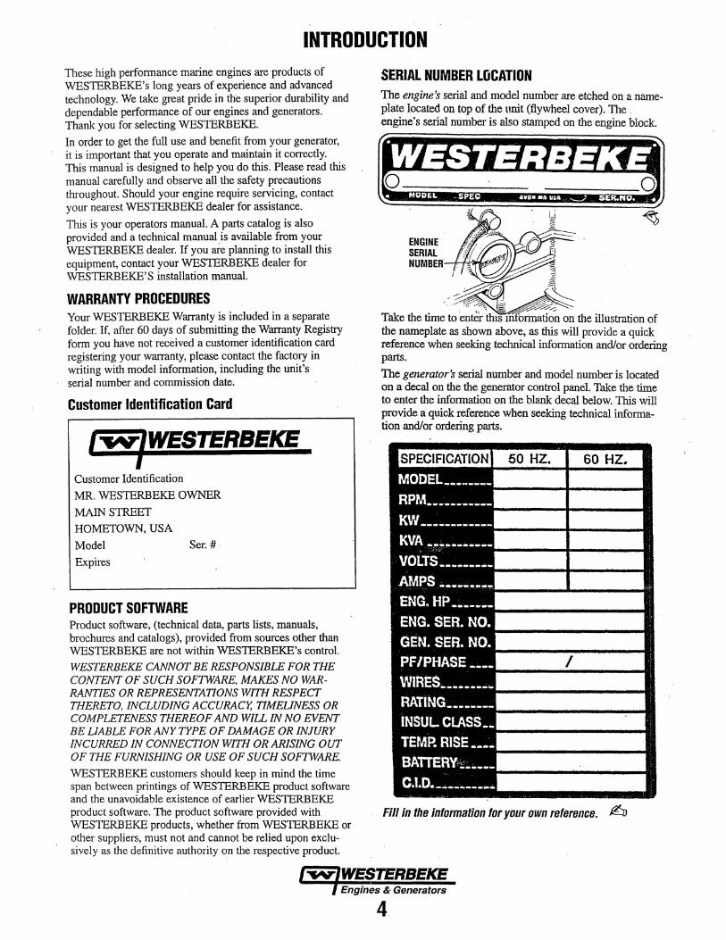
SERIAL NUMBER LOCATION The engine's serial and model number are etched on a nameplate located on top of the unit (flywheel cover). The . engine's serial number is also stamped on the engine block.
ENGINE SERIAL NUMBEK-ll--ftti~roi··
-~a- L ~ .. ..--~·-~ g~~ -
Take the time to enter this ~ation on the illustration of the nameplate as shown above, as this will provide a quick reference when seeking technical information and/or ordering parts.
The generator's serial number and model number is located on a decal on the the generator control panel. Take the time. to enter the infonnation on the blank decal below. This will provide a quick reference when seeking technical information and/or ordering parts.
SPECIFICATION
MODEL---~----RPNI __________ _
KW ___________ _
KVA -----------.:·_:,__,·
VOLTS ________ _
AMPS ---~----ENG. HP------ENG. SER. NO.
GEN. SER. NO.
PF/PHASE ----WIRES ________ .. RATING _______ _
INSUL CLASS __
TEMP. RISE ----BATTERY;,; ____ _
C.1.0. ----------
50 HZ. 60 HZ.
I
Fill in the information for your own reference. $:JJ
4.
INTRODUCTION ORDERING PARTS Whenever replacement parts are needed, always provide the generator and engine model and serial numbers. In addition, include a complete part description and part number for each part needed (see the separately furnished Parts Catalog). Also insist upon WESTERBEKE packaged parts because will fit or generic parts are frequently not made to the same specifications as original equipment.
NOTES, CAUTIONS AND WARNINGS As this manual takes you through the operating procedures, maintenance schedules, and troubleshooting of your generator, critical information will be highlighted by NOTES, CAUTIONS, and WARNINGS. An explanation follows:
NOTE: An operating procedure essential to note.
A CAUTION: Procedures, which if not strictly observed, can result in the damage or destruction of the engine or·generatar.
A WARNING: Procedures, which if not properly ·, followed, can result In personal injury or loss of life.
NOTE: A carbon monoxide warning decal has been provided by WESTERBEKE. Affix this decal in a visible location in the e1J.gine room.
SPARES AND ACCESSORIES Certain spare parts will be needed to support and maintafu your WESTERBEKE generator or engine when cruising (see SUGGESTED SPARE PARTS). Often even simple items s:Uch as proper fuel and oil filters can be difficult to obtain alort.g the way. WESTERBEKE will provide you with a suggested spares and accessories brochure to assist you in preparing an on-board inventory of the proper WESTERBEKE parts.
PROTECTING YOUR INVESTMENT Care at the factory during assembly and thorough testing have resulted in a WESTERBEKE generator capable of many thousands of hours of dependable service. However the manufacturer cannot control how or where the generator is installed in the vessel or the manner in which the unit is operated and serviced in the field. This is up to the buyer/owner-operator.
NOTE: Seven important steps to ensure long generator life:
• Proper engine and generator installation.
• An efficient well-designed exhaust system that includes an anti-siphon break to prevent water from entering the engine.
• Chang;.ng the engine oil and oil filters every 100 operating hours.
• Proper maintenance of all engine and generator components according to the maintenance schedule in this manual.
• Use clean, filtered unleaded fuel. ,.
• Winterize your engine according to the "Lay-up and Recommissioning" section in this manual.
• Raw Water Cooled Model - Flush the engine cooling system according to the procedures found in this manual.
UNDERSTANDING THE GASOLINE GENERATOR TQe gasoline engine driving an AC generator is in many ways similar to a gasoline automobile engine. The cylinders are in-line, and the engine's cylinder head has an overhead camshaft which is belt-driven. The engine incorporates a pressure type lubrication system, and a water-cooled engine block.
To a large degree, the generator's engine requires the same preventive maintenance that is required of a gasoline automobile engine. The most important factors to the generator's longevity are proper ventilation, maintenance of the fuel system, ignition system, and cooling system.
CARBON MONOXIDE DETECTOR WESTERBEKE recommends mounting a carbon monoxide detector in the vessels living quarters. Carbon monoxide, even in small amounts, is deadly. The presence of carbon monoxide indicated an exhaust leak from the engine or generator or from the exhaust elbow/exhaust hose, or the fumes from a nearby vessel are entering your boat. If carbon monoxide is present, ventilate the area with clean air and correct the problem immediately!
Engines & Generate>.rs
5

INSTALLATION RIGGING AND LIFTING The engine/generator is fitted with~lifting eyes~ Attach wire rope or chain slings capable of supporting the engine/generators weight to the eyes and lift the engine/generator by means of tackle attached to these slings. The lifting eyes have been designed to carry the full weight: auxiliary slings are not necessary.
NOTE: Rigging work is best done by someone experienced and competent in handling mo.chin(!ry.
LOCATION AND MOUNTING A solid, level mounting platform is very important for the proper operation of your generator. Select a location that will allow adequate space on all sides for ventilation and servicing. Locate the generator away from living quarters, and away from bilge splash and vapors. Refer to WESTERBEKE'S installation manual for detailed information on iflStalling a Marine Generator in a boat.
. 314n PLYWOOD-BOLTED/FIBERGLASSED
. IN PLACE
BATTERY ATTACHMENTS .. TO STARTER MOTOR REFER TO THE WIRING DIAGRAM IN THIS MANUAL
(·)NEGATIVE LEAD
USE THE PAN AS A TEMPLATE-FOR LOCATING THE PROPER MOUNTING HOLES TO THE PLYWOOD BASE
(+)POSmVE LEAD
AC CONNECTIOM
SIDE VIEW
-RAW WATER INLET 0.51n (2.7mml t,D, HOSE
DIMENSIONAL DRAWINGS
WATER OllTI.ET ANo DISCHARGE HOSES D.5in (2.7mm) l.D.
For dimensional drawings. View the drawings on the Westerbeke website www.westerbeke.com for the most current drawings with dimensions.
Engines & Generators
6

INSTALLATION RAW WATER DISCHARGE The raw water cooled 3.0KW Generator is cooled internally by a continuous flow of raw water.
The fresh water cooled model is cooled internally by fresh water (coolant). This coolant is cooled by a continuous flow of raw water (via the heat exchanger).
Both model generators use the engine cooling raw water to cool the exhaust system as it is discharged overboard. A raw water supply hose delivers the raw water from the engine to the water injected exhaust elbow.
RAW WATER SUPPLY HOSE The raw water supply hose from the discharge connection on the engines cooling system to the inlet connection of the water injected exhaust elbow must be looped a minimum of 12 inches (30cm) above the vessels loaded water line.
On installations where the water injected exhaust is close to or below the vessels loaded water line, provisions must be made to install a syphon break in the raw water supply hose.
The function of the syphon break is to stop the raw water flow after the engine is shutdown. This flow, if not stopped, will fill the exhaust system a?d possibly the engine as well.
The raw water supply hose must be looped well above the loaded water line to allow the syphon break to function during all attitudes of vessel operation to prevent syphoning when the generator is not operating.
~<er>~--'RAW WATER ;DRAIN
HEAT EXCHANGER
When the generators location is above the loaded waterline of the vessel during all attitudes of vessel operation, it is still advisable to loop the raw water discharge hose at least 6 inches or more above the generator and then down to the inlet connection on the water injected exhaust elbow.
NOTE: Always use quality hose with good wall integrity or wire reinforced hose so it will maintain its shape when looped and also provide proper mechanical support for the hose.
#053499 WHEN A SIPHON BREAK SIPHON BREAK IS NOT REQUIRED AVAILABLE FROM RAW WATER ,,,, .. - - ' YOUR WESTERBEKE SUPPLY HOSE // .... ~-"' "\
D~R- /~////' \\\\ ~ ... "·· I I ·i;j}i: - I I I I ..... ~ .... ~ ,,,,... ,,.,...... '\ I I . ... , ... ,,.,,:.... \ I f I I :!." '\ -· ""'' \ I ,' I I ... ,,,..,,.,.,,.. \. I I I
,....-<- ,... I I I I I /- ).,.................... I I l J I i
/ .--~ : I I ! ! I
//~·I:: 1: i ' ' I I I I : ; I ~,_ ~ I I : i ' I . I I I I
I I I I I I 1
WATER I 1 ·1
INJECTED ' : EXHAUST 1
EXHAUST OVERBOARD
EXHAUST SYSTEM
OIL DRAIN HOSE
Engines & Generators
7

FUEL, ENGINE OIL AND ENGINE COOLANT GASOLINE , : A CAUTION:~-----------'-----.
Use unleaded 89 Octane gasoline or higher. Ethanol gasoline must not exceed ElO (10%). Gasoline with higher percentages of Ethanol are not acceptable for use in these models
, _and can void the warrenty.
Care Of The Fuel Supply Use only clean fuel! The clearance of the components in your fuel injection pump is very ctitical; invisible dirt particles which might pass through the filter can damage these finely finished parts. It is important to buy clean fuel, and keep it clean. The best fuel can be rendered unsatisfactory by careless handling or improper storage facilities. To assure that the fuel going into the tank for your engine's daily use is clean and pure, the following practice is advisable:
_ Purchase a well-known brand of fuel.
Install and regularly service a good, Coast Guard approved metal bowl type filter/water separator between the fuel tank and the engine.
ENGINE OIL Use a good brand of engine oil, with an API classification and SAE as stated in the SPECIFICATIONS section of this manual.Change the engine oil and oil filter after the initial 50 hours Of engine break-in operation and then every 100 hours of operation thereafter. -
Westerbeke Corporation does not approve or disapprove of the use of synthetic oil; If synthetic oil is used, engine . break-in must be performed using Conventional oil. Oil change intervals must be as listed in the MAINTENANCE SCHEDULE-'section of this manual and not to be extended if synthetic oil is used. · -
NOTE: The itiformation above supersedes all previous statements regarding synthetic oil.
NOTE: Be very careful not to overfill the oil sump. Overfilling of t~ie oil sump will result in erratic operation of the engine, white-smokeyloil laden exhaust discharge, possible hard starting or no start andfouled spark plugs. Reference Service Bulletin #256.
ENGINE COOLANT . WESTERBEKE recommends a mixture of 50% antifreeze and 50% distilled water. Distilled water is free from the chemicals that can corrode internal engine surfaces. The antifreeze perfonns double duty. It allows the engine to run at proper temperatures by transferring heat away from the engine to the coolant, and lubricates and protects the cooling circuit from rust and corrosion. Look for a good quality antifreeze that contains Supplemental Cooling Additives (SCAs) that keep the antifreeze chemically balanced, crucial to long term protection. The distilled water and antifreeze should be premixed before being poured into the cooling circuit
NOTE: Look for the new environmentally-friendly long lasting antifreeze that is 110W available.
MAINTENANCE Change the engine coolant every five years regardless of the number of operating hours as the chemical additives that ptotect and lubricate the engine have a limited life.
COOLANT RECOVERY TANK The coolant recovery allows for the expansion and
_ contraction of the engines coolant during engine operation without introducing air into the system. This recovery tank is provided with fresh water cooled models and with the fresh water coolant conversion kit and must be installed before operating the engine.
NOTE: T11is tank, with its short run of plastic hose, 1.s best located at or above the level of the engine's manifold, but it can be located below the level of the engine's manifold if the particular installation makes this necessary.
Engines & Generators
8

CONTROL PANEL· START/STOP PROCEDURE DESCRIPTION The control panel provides the operator with a simple stop/start rocker switch and a hourmeter. The plug-in connections for the engine wiring harness, go:vemor sensor and remote panel are located on the side of th~ control panel along with a 10 amp fuse. The ignition control module with it's plug-in wiring is mounted on the top of the panel.
A CAUTION: All AC loads must be switched off before starting. This precaution will prevent damage caused by unanticipated operation o~ AC machinery and will prevent a cold engine from starting
STARTING The engitw has a 12 VDC electric starter: ·
To Start: Press the rocker switch to the start position and release. The engine will crank and start electronically and the switch will show a RED light to indicate the engine is running. Apply a light load to the generator and allow the engine to warm up to operating temperature before applying heavy loads.
NOTE: Some unstable running may occur in a cold engine . condition. This should smooth out as the engine warms up and the generator loads are applied.
A CAUTION: Never operate the engine for Ion~ periods of time without an amperage load being applied, otherwise carbon build·up may occur which can cause severe 'damage to the engine.
STOPPING To Stop: Press the rocker switch to stop and release. The engine will shutdown and the LED light will tum off.
GENERATOR OPERATION
STAR1: Depress switch to START position. START LEO will I ite, engine wil I crank. RUN LEO will remain on when engine is running.
STOP; Depress switch to STOP posi I ion. Engine wi 11 stop, RUN LEO wi II turn orr.
~STERBEKE
ENOiNE Sn>PJST.ART DECAi.
Abnormal Stop (refer to SAFETY SHUTDOWN SWITCHES)
. An abnonnal stop is one in which the generator ceases to run and comes to a stop as a result of an operating fault which may cause damage to the engine, the generator, or create an unsafe operating condition. · · .
START/STOP SWITCH
! MAIN CIRCUIT BREAKER
A WARNING: Should the engine fail to start once the start switch has been depressed, a crank limit circuit will disengage the starter and stop the starting cycle. This will occur after approximately 15 seconds of cranking with no start. This is ta prevent prplonged cranking without the engine starting which can result in the exhaust system filling with water and backing into the engine.
REMOTE PANEL A remote panel is available that allows for remote operation of the generator. The panel comes with either a 15' or 30' plug-in extension harness. The start/stop sequence is identical. Once installed, the engine can be operated by either panel.
(V\Tl WESTERBEKE" I
START ?=' ~
0 I 0
NOTE: Holding the start button depressed will keep the start circuit engaged. . ' - -· ·-
..
l STOP
Engines & Generators
g

PREPARATIONS FOR, INITIAL START-UP PRESTART INSPECTION Before starting your generator set for the first time or after a prolonged layoff, check the following items: • Make certain the cooling water thru-hull petcock is open. •, Check the engine oil level: add oil to maintain the level at
the full mark on the dipstick. • Check the fuel supply and exarriine the fuel filter/separator
bowls for contaminant's. • Check the DC electrical system. Inspect wire connections
and battery cable connections. • Check load leads for correct connection as specified in the
, wiring diagrams. • Examine air inlet anµ outlet for air flow obstructions. • Be sure no other generator or utility power is connected to
load lines. • Be sure that in power systems with a neutral line that
the neutral is properly grounded (or ungrounded) as the system requires, and that the generator neutral is properly connected to the load neutral. In single phase systems ati incomplete or open neutral can supply the wrong line-toneutral voltage on unbalanced loads.
• Visually examine the unit Look for loose or missing parts, disconnected wires, unattached hoses, and check threaded connections. Search for any gasoline leaks.
• Check the coolant level in bott1 the plastic recovery tank and at the manifold.
SPIN-ON OILFILTER',
NOTE: After the initial running of the generator, the air in the engine's cooling system will be purged to the coolant recovery tank. Open the air bleed petcock to ensure that the cooling system is purged of air. After shutdown and
. after the engine has cooled, the coolant from the recovery tank will be drawn into the engine's cooling system to replace the pflrged air.
Before subsequent operation of the g~erator, the engine's manifold should be topped off. and the coolant recovery tank_m_ay need to be filled to the MAX level.
A CAUTION: When starting the genera.tor, it is recommended that all AC loads, especially large motors, be switched OFF until the engine has come up to speed and, in cold climates, starts to warm up. This precaution wfll prevent damage caused by u11anticipated operation of the AC machinery and will prevent a cold engine from stalling.
THERMOSTAT HOUSING
·. COOLANT PRESSURE CAP
~. TO COOLANT t.· RECOVERY
TANK
COOLANT TEMPERATURE SWITCH
COOLING WATER BY-PASS INSPECT PERIODICALLY
Engines & Generators
10

SAFETY SHUTDOWN SWITCHES
SAFETY SHUmOWN SWITCHES This engine is protected by three shutdown switches and two fuseS. Should a shutdown occur, do not attempt to restart without_jUulin,g and correcting the cause. Refer to
· the heading Engine Siarts, runs .and then shuts down in the ENGINE TR.OUBLESHOarING s;ection of this manual.
OVERSPEED PC BO~ The overspee1:i"PC ~ard inside th~ control panel will shut · the engine down "if the engine speed (RPM'S) exceeds the ,operating speed required to run the generator. The overspeed PC board will reset itself once the engine shuts down. ·
10AfUSE
OVERSPEED PC BOARD
MAIN AC CIRCUIT BOARD
MAIN CIRCUIT BREAKER AC The mam circuit breaker at the control panel will automatically disc;:onnect the AC power if there is an electrical overload. Tum off the AC breaker and remove the 10 amp panel fuse when servicing the unit as a safety precaution.
FU$ES A JOA fuse lOca.t.ed on the side of the control panel protects the DC el~trical wiring. If an .electrical overload occurs the fuse will blow and shut the engine down. An 20A in-line fuse protects the battery .charging circuit If this fuse fails, .the engine will continue to run but the battery will .IJ.~t be charging.
10AFUSE .2DAFUSE BATTERY CHARGING
11
EXHAUST TEMPERATURE SWITCH An exhaust temperature switch located at the base of the exhaust elbow sensors an excessive exhaust temperature (an inadequate supply of cooling water). A temperature above 240° F will shut the engine down. Inspect the cooling system, wat.er pump, pump belt, seacock, water strainer, water hoses, etc. This switch will reset itself when the exhaust cools.
LOW Oil SWITCH
EXHAUST 8.BOW
Located just to the right of the oil :filt.er, this switch ~ the engine's oil pressure if the oil pressure falls to below 5 psi. This switch will shut the engine down. Check the angle of operation, dipstick oil level and oil filter. The switch will reset itself.
LOW OIL PRESSURE SWITCH
67 OJt FIL1tH {); J
HIGH WATER TEMPERATURE SWltcH (Fresh Water :Cooled :Model)
-·~
\. \
A high water temperature switch is located at the thermostat housing, Normally closed, this switch, should the fresh water coolant's operating temperature reach approximately 210"F (99°C), will open and shut the engine down. This switch resets itself at l95"F (107°C). ·
--~==~
· THERMQSTAT HOUSING

MAINTENANCE SCHEDULE WARNING: Never attempt to pertonn any service while the engine is mnning. Wear the proper safety equipment such as goggles and gloves, and use the correct.tools for each job. When servicing/replacing DC components, tum off the 20 amp DC circuit breaker an the control panel, or disconnect the battery terminals.
SCHEDULED MAINTENANCE Maintenance procedures are all detailed in this manual.
I DAILY CHECK BEFO!lE START-UP
Coolant Level
Engine Oil Level
Fuel/Water Separator (owner installed)
Fuel Supply
Visual Inspection of Engine
I INITIAL 50 HOURS OF OPERATION
Valve Clearance
Generator Drive BeH
Engine Oil and Filter
Exhaust System
Zinc Anode
Fuel Fitter
Inlet Fuel Fitter
Spark Plugs
Rame Arrester Screen
Water Pump
I EVERY 50 OPERATING HOURS OR MONTHLY
Starting Batteries (and House Batteries)
Fuel Pump
Zinc Anode
I EVERY 100 OPERATING HOURS OR YEARLY
Engine Oil and Filter
Air Intake and Filter
Timing Bell
Spark Plugs lmpeller(s)
EXPLANATION OF SCHEDULED MAINTENANCE
Check at recovery tank, if empty, check at manifold. Add coolant if needed.
Oil level should indicate between MAX and LOW on dipstick. Do not overfill! CAUTION: The oil sump on this generators engine can unintentionally be over-mledl }\fter sht.it-down, the oil in the engines internal passag~s can linger and take a number of hours to drain back into the oil sump. Allow at least a few hours for the oil to settle back into the sump before checking the dipstick. An overnight period will provide an even more accurate dipstick reading. (Re-starting the engine is not a problem as the engine's internal passages are well lubricated).Over-filling the engines sump will result in erratic operation, and/or smokey white oil laden exhaust, hard starting and possibly no start.
Check for water and dirt in fuel. Drain filter if necessary. Repla~e filter every 250 operating hours or once a year,
Fresh unleaded gasoline with an octane rating of 89 or higher.
Check for fuel, oil and water and exhaust leaks. Check for rust or corrosion. Inspect wiring and electrical connections. Ensure that bolts and nuts are tight. Surface of engine should be kept clean.
Initial adjustment (engine cold).
Measure spring length. Inspect belt condition. Adjust spring length as needed.
Initial engine oil and filter change at 50 hours, then change both every 100 hours.
Initial check at 50 hours, then every 250 hours or once a year. Carefully inspect for leaks. Check anti-siphon valve operation. Check that the exhaust elbow for carbon and/or corrosion buildup on inside passages: clean and replace as necessary.
Inspect/clean.
Initial change.
Initial change.
Check gap (0.035in (0.8 - 0.9mm).
Initial cleaning of screen.
Adjust belt tension (3/8 -1/2 deflection).
Check electrolyte levels Make sure cables and connections are in good order. Clean off corrosion if needed. Apply petroleum jelly to terminals for corrosion protection.
Inspect for leaks, ensure fuel and electrical connections are clean and tight.
NOTE: Work out your own schedule, boats location, use of s/'tore power can make a difference. Inspect monthly to determine schedule.
Change engine oil and filter.
Remove, clean and re-install screen pack.
Check for wear, cracks and stretching.
Inspect plug gap. AdjusVreplace as .needed.
Inspect impeller(s) for condition. Rep~ce as needed.
NOTE: Refer to Service Bulletin #276 dated 6 May 2015 when performing generator drive belt adjustment.
Engines & Generators
12

MAINTENANCE SCHEDULE NOTE: Use the engine hounneter gauge to log your engine hours or record your engune hours running time.
SCHEDULED MAINTENANCE EXPLANATION OF SCHEDULED MAINTENANCE
I EVERY 250 OPERATING HOURS OR YEARLY
Valve Clearance Adjust valves. ·-------------------·---~-
Generator Wipe generator clean of dust and engine exhaust. Remove vent cover and inspect for loose connections and overheated wires or windings. Make certain vents are clear and unobstructed.
*Exhaust CO level Sample exhaust with CO analyzer. ·-----------------------------------------~
*Exhaust Elbow Check exhaust elbow for structural integrity. Replace if elbow is corroded or deteriorated.
Exhaust System
*Exhaust System Back Pressure
Fuel Filter and O·Rings
Inlet Fuel Filter
Generator
Hoses
Always use a new gasket. NOTE: A leaking exhaust elbow or gasket can cause exposure to carbon monoxide!
Carefully inspect for leaks. Check anti-siphon valve operation. Check the exhaust elbow for carbon and/or corrosion build-up on inside passages. Clean and replace as necessary.
·----Perform back pressure test to ensure has not developed restrictions that will increase pressure above 1.5 psi or 41 inches of water column at full opera~ing amperage load. Correct as needed.
Remove and replace fuel filter and all sealing 0-rings.
Remove and replace inlet fuel filter.
Check that AC connections are clean and secure. Ensure wires have no chafing. See GENERATOR INFORMATION.
Engine hoses should be firm and tight. Replace if hoses become spongy, brittle or delaminated. Check and tighten all hose clamps as needed.
·~---~~---~--~-~-------- --------~----~
Vibration Isolators/Engine Mounts ·~-----·~~~--~~
Zinc Anode
Generator Drive Bell
I EVERY 500 OPERATING HOURS OR YEARLY
R11w Waler Pump
I EVERY 500 OPERATING HOURS OR EVERY TWO YEARS
Coolant System
Valve Clearances ----
Starter Motor
Dlverter Valve
Check vibration isolators, brackets and mounting brackets. -~-~~---~--~----
Remove and replace zinc anode. Open heat exchanger and cap(s) and clean out debris. Replace gasket and 0-rings if needed. "
Measure spring length, inspect belt condition. Adjust spring length as needed. NOTE: Refer to Service Bulletin 276 dated May 6, 2015.
Remove the dual pumps. Follow the instructions in this manual and disassemble both pumps. Inspect and replace any worn parts. Lubricate, reassemble and install. With engine running, check for leaks and for proper pumping action.
Drain, flush and re-fill the cooling system with appropriate antifreeze mix. Replace the thermostat and coolant pressure cap.
Incorrect valve clearance will result in poor engine pertormance Adjust valves engine cold.
Check solenoid and motor for corrosion. Remove and lubricate. Clean and lubricate the starter motor pinion drive.
Replace.
EVERY 1000 OPERATING HOURS OR OR EVERY FIVE YEARS
Heat Exchanger
I EVERY 2000 OPERATING HOURS
•oxygen Sensor ·-----
•catalyst
*WESTERBEKE recommends this service be performed by an knowledgeable mechanic.
Remove the heat exchanger for professional cleaning and pressure testing.
Remove and replace exhaust oxygen sensor. Inspect every 1000 hours
Remove and replace exhaust catalyst.
NOTE: The operation of the unit's "Low-CO" system must be monitored at least once an operating system. 11iis is to help ensure that the system is operating properly. Contact your Westerbeke dealer to have this service pelfonned on your generator.
En_qlnes & Generators
13

ENGINE LUBRICATING Oil
!ENGINE OIL Use a good brand of engine oil with an API ~ SAE designations as listed in the SPECIFICATION Section of this manual. Change the engine oil ~filter after an initia1•50 hours of engine l>:reak-in operation. Then follow the oil and filter change interval as specified in the MAJNTENANCE SCHEDULE in this manual.
Westerbeke Corporation does not approve pr disapprove the use of synthetic oils. If synthetic oils are used, engine breakin must be performed using conventional oil Oil change intervals must be as listed in the MAINTENANCE SCHEDULE section of this·mailual and not be extended if synthetic oils are used. NOTE: The information above supersedes all previous statements reganii.ng synthetic oiL ·
CHANGING THE ENGINE OIL The engine oil should be warm. Remove the oil drain hose from its attachment bracket and lower it into a container and allow the oil to ililirl, or attach a pump to the end of the drain hose and pump the old oil out. Make sure the oil drain hose is properly secured in its holder after all of the old oil has been drained. ~-~.':;r:1'''':·.:··-..
I A WARNING: Used engine oil contains harmful contaminants. Avoid prolonged skin contact. Clean skin and nails thoroughly using soap and water. Launder or discard clothing or rags containing used oil. Discard used oil properly.
Always observe the old oil as it is removed. A yellow/gray emulsion indicates the presence of water in the oil. Although this condition is rare, it does require prompt attention t<;> prevent serious damage. Call a competent mechanic if water is present in the oil. Water present in the oil can be the result of a fault in the exhaust system attached to the engine and/or a siphoning through the water cooling circuit into the exhaust, filling it up into the engine.
INLET FUEL FILTER To ensure clean fuel into the fuel lift pump, there is a small in-line fuel filter connected to the fuel module. This filter should be replaced every 250 hours of operation.
WIPE THIS SURFACE CLEAN BEFORE INSTALLING FILTER
CHANGING THE Oil FILTER
OIL FILTER ASSEMBLY
.OIL PRESSURE SWITCH
OIL FILTER •WRENCH
When removing the used oil filter, you may find it helpful to punch a hole in the upper and lower portion of the old filter to drain the oil into a container before removing it. This helps to lessen spillage. An automotive filter wrench should be helpful in removing the old oil filter. Place some pll,per towels and a plastic bag around the filter when unscrewing it to catch any oil that's in the filter. Inspect the old oil filter as it is removed to make sure that the rubber sealing gasket comes off with the old oil filter. If this rubber sealing gasket remains sealed against tlie oil filter adapter, gently remove it. When installing the new oil filter element, wipe the filter gasket's sealing surface on the oil filter adapter free of oil and apply a thin coat of clean engine oil to the rubber sealing gasket on the oil filter. Screw the filter onto the threaded oil filter stub, and tighten the filter firmly by hand.
NOTE: Use genuine WESTERBEKE oil.filters. Generic.filters are not recommended.
REFILLING THE OIL SiJMP Add fresh oil through the valve cover. After refilling the oil, run the,engip~ for a few moments while checking the engine's oil presslire. Make.•sure there is no leakage around the new oil filter or from the oil drain system, and then stop the engine. Then check the quantity of oil with the lube oil dipstick. Fill to the FUlL mark on the dipstick.
OVER-FILLING CAUTION: The oil sump on this generator's engine can unintentionally be over-filled! After shutdown, the oil in the engines internal passages can linger and take a number of hours to drain back into the oil sump. Allow at least a few hours for the oil to settle back into the sump before checking the dipstick. An overnight pe1iod will provide an even more accurate dipstick reading.
(Re-starting the engine is not a problem as the engine's internal passages are well lubricated).
Over-filling the engine's sump will result in erratic operation, and/or a smokey white oil laden exhaust, hard starting and possible no start.
Engines & Generators
14

FUEL SYSTEM GASOLINE
A CAUTION: Use unleaded 89 Octane gasoline or higher. Ethanol gasoline must not exceed must not exceed E1D(itJ%}. Gasoline with higher percenf!Jges of· Ethanol are not acceptable far use in. these models and can void the warranty.
OWNER INSTALLED FUEL WATER SEPERATOR (WESTERBEKE PART #49602}
. . -GASOLINE/WATER SEPARATOR A primary fuel filter of the water separating tjpe must be installed between the fuel tank and the engine to remove water and other contaminan(s from the fuel before they can be carried to the fuel system on the engine.
These gasoline filters must have metal bowls (not "seethrough") to meet U.S .. Coats Guard requirements. The metal bowls have drilin valves to use when checking for water and impurities.
Care Of The Fuel Supply Use only clean fuel! The clearance of the components in your fuel injection pump is very critical; invisible dirt ' particles which might pass through the filter can damage th~e finely finished P.arts. It is important to buy clean fuel, .
1 A WARNING: Shut a" the fuel valve at the tank when servic.ing the fuel system. Take care in catching any fuel that may spill. DO NOT allow any smoking, open names or'other sources of fire near the fuel system when servicing. Ensur~ proper ventilation exists when servicing the fuel system.
FUEL PUMP Periodically che.Ck the fuel connections to and out of the pump and make sure that nQ leakage is present.and that the fittings . are tight and secure. The engine mounted fuel pump is maintenance free.
A WARNING: Fuel leakage at the fuel pump or its connections Is a fire hazard and should be corrected. Make sure proper ventilation exists whenever Sf!rvicing. fuel system co_mponents.
NOTE: The generator compartment should have a gasoline fume detector/alarm properly installed and working.
. ':,:"· -: . INCOMING FUEL ENGINE FUEL FILTER~ . . Periodically check the fuel connections ~- the filter bowl for leakage. Change the filter element after the first 50 hours. s~ the MAJ!fTENANCE SC.HEDUIE.
Changing the Filter Element 1. Shut off the fuel supply. · 2. . Unscrew tile filter bowl from the housing and allow bowl
· to come away from the housing.Remove and replace the filter element and clean the bowl.
3. Remove and replace the filter element and clean the bowl 4. Inspect both 0-rings. Replace,: 5. Press on a new filter and replace the filter bowl.
A WARNING: Fuel Is present In the hosing and lines. Use extreme care to prevent spillage
ENGINE FUEL FILTER
REPLACE BOTH 0-RINGS
LUBRICATE WITH CL£4N FUEL AND PRESS THE FILTER . ON OVER THE 0-RING
. -.·w-WESTERBEKE Engines & Gene(ators
15
COOLING SYSTEM
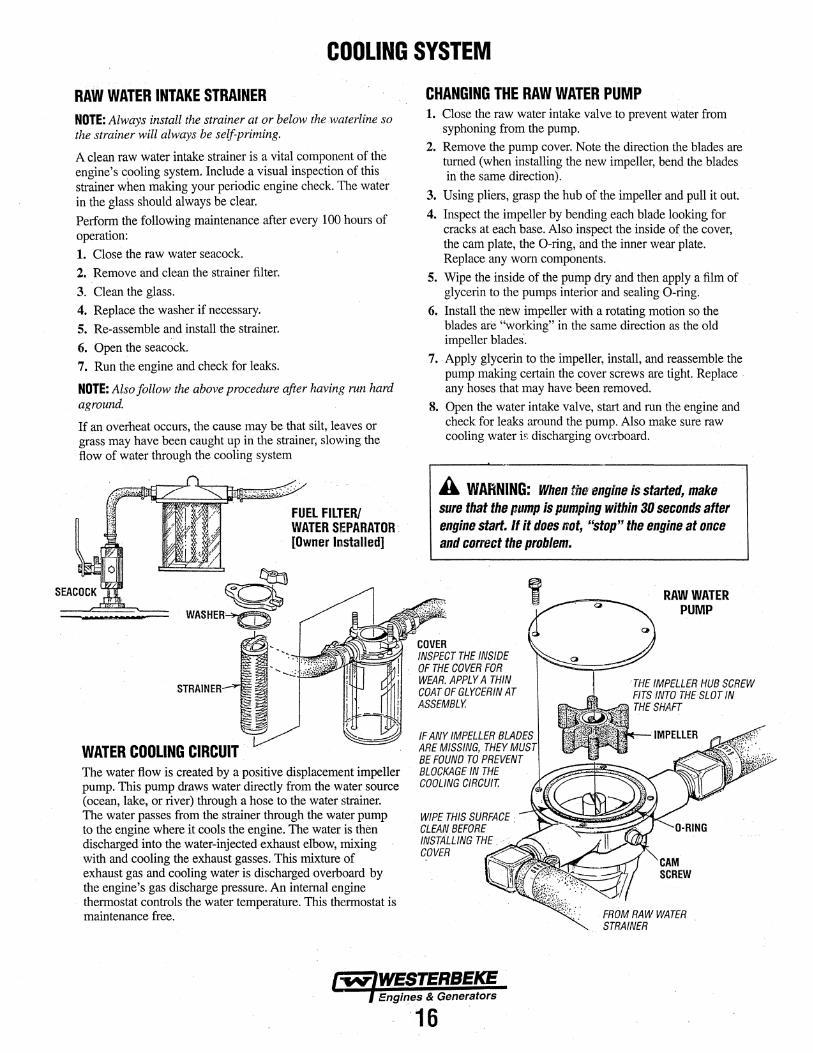
RAW WATER INTAKE STRAINER NOTE: Always install the strainer at or below the waterline so the strainer will always be self-priming.
A clean raw water intake strainer is a vital component of the engine's c.ooling system. Include a visual inspection of this strainer when making your periodic engine check. The water in the glass should always be clear. Perform the following maintenance after every 100 hours of operation: 1. Close the raw water seacock. 2. Remove and clean the strainer filter.
3. Clean the glass. 4. Replace the washer if necessary. 5. Re-assemble and install the strainer. 6. Open the seacock. 7. Run the engine and check for leaks.
NOTE: Also follow the above procedure after having run hard aground.
If an overheat occurs, the cause may be that silt, leaves or grass may have been caught up in the strainer, slowing the flow of water through the cooling system
~ Q
WASHER >(j)
STRAINER
WATER COOLING CIRCUIT .
FUEL FILTER/ WATER SEPARATOR· [Owner Installed]
The water flow is created by a positive displacement impeller pump. This pump draws water directly from the water source (ocean, lake, or river) through a hose to the water strainer. The water passes from the strainer through the water pump to the engine where it cools the engine. The water is then discharged into the water-injected exhaust elbow, mixing with and cooling the exhaust gasses. This mixture of exhaust gas and cooling water is discharged overboard by the engine's gas discharge pressure. An internal engine
· thermostat controls the water temperature. This thermostat is maintenance free.
CHANGING THE RAW WATER PUMP 1. Close the raw water intake valve to prevent water from
syphoning from the pump. 2. Remove the pump cover. Note the direction the blades are
turned (when installing the new impeller, bend the blades in the same direction).
3. Using pliers, grasp the hub of the impeller and pull it out.
4. Inspect the impeller by bending each blade looking for cracks at each base. Also inspect the inside of the cover, the cam plate, the 0-ring, and the inner wear plate. Replace any worn components.
5. Wipe the inside of the pump dry and then apply a film of glycerin to the pumps interior and sealing 0-ring.
6; Install the new impeller with a rotating motion so the blades are "working" in the same direction as the old impeller blades·.
7 •. Apply glycerin to the impeller, install, and reassemble the pump making certain the cover screws are tight. Replace . any hoses that may have Been removed.
8. Open the water intake valve, start and run the engine and check for leaks around the pump. Also make sure raw cooling water is discharging overboard.
A WARNING: When the engine is started, make sure that the pump is pumping within 30 seconds after engine start. If it does not, "stop" the engine at once and co«ect the problem~ ·
COVER INSPECT THE INSIDE OF THE COVER FOR WEAR. APPLY A THIN COAT OF GLYCERIN AT ASSEMBLY.
IF ANY IMPELLER BLADES ARE MISSING, THEY MUST BE FOUND TO PREVENT BLOCKAGE IN THE COOLING CIRCUIT.
WIPE THIS SURFACE CLEAN BEFORE INSTALLING THE ... : COVER .--..--.-~""
RAW WATER PUMP
CAM SCREW
FROM RAW WATER STRAINER
Engines & Generators
'16

COOLING SYSTEM [FRESH WATER COOLED MODELS]
RAW WATER PUMP (Fresh Water Pump) The fresh water cooled model has the raw water pump mounted above the fresh water (coolant) pump as illustrated. This pump is a self-priming, rotary pump with a non-ferrous housing and a Neoprene impeller. The impeller has flexible blades that wipe against a curved cam plate within the impeller housing, producing the pumping action. Qn..nQ account should this. pump be run dry. There should al ways be a spare impeller and impeller cover gasket aboard (an impeller kit). Raw water pump impeller failures occur when lubricant (water) is not present during engine operation. Such failures are not warrantable, and operators are cautioned to make sure water flow is present at start-up. The raw water pump should be inspected periodically for broken or tom impeller blades. See MAINTENANCE SCHEDULE.
NOTE: Should a failure occur with the pumps internal parts . (seals and bearings) it may be more dJst efficient to purchase a new pump and rebuild the original pump as a spare.
DUAL PUMPS (FRESH WATER COOLED MODELS)
0-RING
PUMP C"OVER INSPECT THE INSIDE SURFACE FOR WEAR.
IMPELLER FIT THE HUB SCREW INTO THE SHAFT SLOT
WHEN ASSEMBLING, COAT . THE IMPELLER AND 0-RING WITH GLYCERIN
' WIPE THIS SURFACE CLEAN BEFORE INSTALLING THE 'COVER
DRAIN TUBE
CHANGING THE WATER (Pump) IMPELLERS Remove the cover screws and the cover will separate the upper pump (raw water) from the fresh water (coolant) pump as shown in the illustration. Close the raw water thru hull seacock. This will prevent water syphoning out of the pump while the impeller is being changed. 1. Remove the wear plate to expose the impeller. Notice the
direction the impeller blades are working in so as to install the replacement impeller with blades working in the same direction.
2. Using pliers, grab the impeller hub and withdraw the impeller from the pump. Inspect the inside of the pump, the cam, the inner wear plate, and the inside surface of the cover plate for wear. Replace any worn components.
3. Wipe the inside surface of the pump dry. Apply a film of glycerin supplied in the impeller kit to the inside pump surfaces and to the exposed area of the shaft lip seal.
4. Install the new impellers with a rotating motion so the blades are working in the same direction as those of the removed impeller.
5.. Apply glycerin to the 0-ring, impeller, gasket, the wear plate and assemble into the pump housing. Reassemble the lipper pump (raw water) making certain the fasteners are tight: Re-install any hoses that were removed.
6. Ru~ the engine to make certain both pumps are operating properly. The engine should run at proper temperature. raw.water should discharge from the exhaust and there should not be any leaks around the pumps.
A WARNING: When the engine is started, make sure that the pump is pumping within 30 seconds after engine start. If it does not, "stop" the engine at once and correct the problem.
To increase the service life of the impeller, do not install the impeller in the pump if the engine will be in storage for longer than 3 months. Store the impeller in a dark, cool, and
... dry location. Replace the cover plate on the pump securely ·'' and ensure the thru hull seacock is closed.
WATER INTAKE STRAINER A water intake strainer (raw water) is a required component when the generator is installed. Refer to the previous page for details.
NOTE: Shouid a pump shaft water seal leak occur, this drain tube will allow the leak to drain away from the unit. Keep this drain tube clear of obstructions.
Engines & Generators
17

, RAW WATER PUMP IMPELLER
DESCRIPTION Coolant (fresh water) cooled generators have dual water pumps while the raw water cooled models use a single water pump. The pumps are essentially the same. The upper pump mounts to the top of the lower pump and has a tang on the shaft that fits into the shaft of the lower pump. Both pumps are driven simultaneously by the engines drive belt.
The following instructions apply to either pump.
PUMP OVERHAUL Disassembly The pump, when removed from the engine will have the hose attachment nipple threaded into the inlet and outlet ports of the pump along with a drive pulley attached to the shaft of the pump. Remove these attachments noting their positions before starting the pump disassembly.
1. Remove the four cover plate screws, cover plate, and sealing 0-ring.
Dual Pumps Remove the cover screws and the cover will separate the upper pump (raw water) from the fresh water (coolant) pump as shown in the illustration
Remove the wear plate to expose the impeller. Notice the direction the impeller blades are working in so as to install the replacement impeller with blades working in the same direction.
2. Remove the impeller using a pair of pliers, grasping the hub and pulling it out of t11e pump with a twisting motion.
3. · Remove the screw and sealing washer that hold the cam in place. Remove the cam and inner wear. plate behind it.
4. Remove the brass circlip A and brass plate found behind the wear plate.
5. ·Remove the dust pla,te and circlip B.
6. Support the pump body on an arbor press and with a drift, carefully press the shaft and bearing assembly out of fue pump body out fue pulley end.
7. Remove fue slinger 0-ring from the shaft.
8. Support fue outer bearing and push the shaft out of the bearing. ·
9. Remove the spacer and circlip C.
IO.Support the inner bearing and push the shaft out of the bearing.
11.Remove the two piece ceramic shaft water seal.
Inspection Inspect all parts and replace those showing wear and corrosion.
INSPECTION: CHECK AT THE BASE OF EACH BLADE BY BENDING VIGOROUSLY. REPLACE THE IMPELLER IFTHERE
"" ARE ANY CRACKS.
~°' COVER
INSPECT THE 0-RING ANO IMPELLER. REPLACE IF ANY SIGNS OF WEAR OR TEARING
DUST
IMRELLER PIN FITS INTO SHAFT
SHAFT
SLINGER 0-RING
l~NER BEARING
SPACER
OUTER BEARING
° CIRCLIP c
PLATE ~.· t'~~'cjf
LIGHTLY GREASE THE PUMP CHAMBER WITH GLYCERIN
PULLEY
Engines & Gener~tors
18

RAW WATER PUMP Reassembly Wipe the inside surface of the pump dry. Apply a film of · glycerin supplied in the impeller kit to the inside pump surfaces and to the exposed area of the shaft lip seal.
1. Install a new shaft seal in the pump body. Apply some glycerin to the lip of the seal.
2. Install the circlip shaft. Support the outer bearing and push the shaft into the bearing until the bearing contacts the circlip.
3. Install the spacer against the circlip. Support the inner bearing and push the shaft into the bearing until it contacts the spacer.
4. Warming the pump body should aid in installing the shaft and bearing assembly. Support the pump body on an arbor press. With a twisting motion, install the shaft and bearing assembly into the pump until the inner bearing seats and the outer bearing should just clear the boss for circlip B. Rotate the shaft. It should turn freely.
5. Install circlip B and push the shaft assembly until the outer bearing just contacts circlip B and install the dust plate. Rotate the shaft. It should turn freely.
6. Put some glycerin on the outer surface of the ceramic seal seat and slide it over the shaft white ceramic facing out and seat it in the body of the pump. Place some glycerin on the inner area and with a twisting motion slide it over the shaft until the ceramic of the spring seal touches the white ceramic face.
7. Install the brass plate and circlip A. 8. Install the wear plate, locking it in position on the dowel
pin.
Dual Pumps The wear plate is assembled above the impeller.
9. Install the cam and place some gasket cement on the threads of the screw that secures it in place.
10.Place some glycerin on the inner surface of the pump, the inner surface of the cover and the cover sealing 0-ring and with a twisting motion install the impeller on the shaft of the pump. Install the covers 0-ring and cover and secure the cover with the four cover screws.
NOTE: Install the new impellers with a rotating motion so the blades are working in the same direction of those of the removed impeller.
Dual Pumps Assemble the upper pump to the lower pump as illustrated making sure the mounting screws are tight.
UPPER. PUMP SHAFT
THE TANG Off THE END OF THE UPPER SHAFT FITS INTO THE SLOT IN THE LOWER SHAFI
~
PULLEY
Engines & Generators
19
SCREWS (}11 FASTENS rHE · ilJ UPPERPUMP
BODYTOmE LOWER PUMP
THE O·RING!GASKET . ONLY NEtos TO BE REPLACES IF IT SHOWS SIGNS OF AGING.
DUAL PUMPS ASSEMBLY

COOLING SYSTEM [FRESH WATER COOLED MODELS] FRESH WATER COOLING CIRCUIT Fresh water coolant is pumped through the engine by a circulating pump, absorbing heat from the engine. The coolant then passes through the thermostat into the manifold, to the heat exchanger where it is cooled and returned to the engine block via the suction side of the circulating pump. When the engine is started cold, external coolant flow is prevented by the closed thermostat (although some coolant flow is bypassed around the thermostat to provide coolant circulation in the engine block). As the engine warms up, the thermostat gradually opens, allowing full flow of the engine's coolant to flow unrestricted to the external portion of the cooling system.
ENGINE COOLANT WESTERBEKE recommends a mixture of 50% antifreeze and 50% distilled water. Distilled water is free from the chemicals that can corrode internal engine surfaces.
The antifreeze perfonns a double duty. It allows the engine to run at proper temperatures by transfening heat away from the engine to the coolant and lubricates and protects the cooling circuit from rust and corrosion. Look for a good quality antifreeze that contains Supplemental Cooling Additives (SCA' S) that keep the antifreeze chemically balanced, crucial to long term protection.
NOTE: Look for the new environmentally friendly long lasting antifreeze that is now available.
The recommended 50/50 mixture will protect the engine against the most extreme temperature. The antifreeze mixture will also retard rust within the engine and add to the life of the circulating pump impeller and seals.
A proper 50/50 mixture as recommended will protect the engine coolant to temperatures of - 40°F.
Coolant Recovery Tank The coolant recovery tank allows for the expansion and contraction of the engines coolant during engine operation without introducing air into the system. This recovery tank is provided with fresh water cooled models and with the fresh water coolant conversion kit and must be installed before operating the engine.
NOTE: This tank, with its short run of plastic hose, is best located at or above the level of the engine's manifold.
NOTE: Periodically check the condition of the pressure cap. Ensure that the upper and lower rubber seals are in good condition and check that the vacuum valve opens and closes tightly. Carry a spare cap.
CHANGING COOLANT The engine's coolant must be changed according to the MAINTENANCE SCHEDULE. If the coolant is allowed to become contaminated, it can lead to overheating problems.
A CAUTION: Proper cooling system maintenance is critical; a substantial number of engine failures can be traced back to cooling system corrosion.
Drain the engine coolant by loosening the drain plug on the heat exchanger and opening pressure cap. Also loosen the air bleed petcock on the top of the heat exchanger
A WARNING: Beware of the hot engine coolant. Wear protective gloves.
Refilling the Coolant Tighten the heat exchanger drain plug and slowly pour clean, premixed coolant in thru the coolant fill. Leave the heat exchanger air bleed petcock loose to allow trapped air to escape. As the filling continues, start and run the engine. Close the air bleed petcock and fill until coolant tops off at the coolant fill. Install the pressure cap.
Remove the cap on the coolant recovery tank and fill with coolant mix to halfway between LOW and MAX and replace the cap. Run the engine and observe the coolant expansion flow into the recovery tank.
After checking for leaks, stop the engine and allow it to cool. Coolant should draw back into the cooling system as the engine cools down. Add coolant to the recovery tank if needed and make certain the coolant is topped off at the pressure cap. Clean up any spilled coolant.
lw/WESTERBEKE / Engines & Generators
20

COOLING SYSTEM [FRESH WATER COOLED MODELS] TO WATER COOLED
THERMOSTAT· Fresh water cooled 3;0KW generators have a thermostat that, controls the coolant temperature as the coolant continuously flows through the closed cooling circuit. When the engine is first started~ the closed thermostat prevents coolant from flowing (some coolant is around the thermostat to provide coolant circulation in the engine block). AB the engine warms up, the thermostat gradually opens. The thermostat is accessible and can be checked, cleaned, or replaced easily. Carry a spare thermostat and gasket
Replacing the Thermostat Remove the cap screws and disassemble the thermostat housing as shown. When installing the new thermostat and. ~ gasket, apply a thin coat of sealant on both sides of the \J;r"" gasket before pressing it into place.
GASKET ADD SEALANT. AT ASSEMBLY
THERMOSTAT HOUSING
HEAT EXCHANGER Cool raw water flows through the inner tubes of the heat exchanger. As the engine coolant passes around these tubes, .the heat of the internal engine is conducted to the raw water which is then pumped into the exhaust system and discharged. The engine coolant (now cooled) flows back through the engine and the circuit repe:'l.ts itself. The engine coolant and raw water are independent of each other; this keeps the engine's water passages clean from the hannful deposits found in raw water.
Heat Exchanger Service After approximately 1000 hours of operation, remove; dean and pressure test the engine's heat exchanger. (A local automotive radiator shop should be able to clean and test the heat exchanger.)
NOTE: Operating in silty and/pr tropical waters may require that a heat exchanger cleaning be perfonned more often than every 1000 hours.
EXHAUST
~a..1-----~ COOLANT DRAIN
H?<------RAW WATER DRAIN
~ CLEAN OUT DEBRIS . O·RING AND GASKET
ZINC ANODE A zinc anode, or pencil, is located in the raw water cooling circuit within the heat exchanger. The purpose of the zinc anode is to sacrifice itself to electrolysis action taking place in the 'raw water cooling circuit, thereby reducing the effects of electrolysis on other components of the system. The condition of the zinc anode should be checked monthly and the anode cleaned or replaced as required. Spare anodes should be carried on board.
NOTE: Electrolysis is the result of each particular installation and vessel location; not that of the engine.
NEW REPLACE CLEAN & REUSE
If the zinc pencil needs replacement, hold the hex boss into which the zinc pencil is threaded with a wrench while loosening the anode with another wrench. This prevents the hex boss from possibly tearing off the exchanger shell. After removing the zinc, note. the condition of it. If the zinc is in poor condition, there are probably zinc flakes within the exchanger. Remove the end of the heat exchanger and clean the inside of all zinc debris. Always have a spare heat exchanger end gasket in case the present one becomes damaged when removing the end cover. Replace the gasket (refer to your engine model's heat exchanger end gasket part number), o-ring, cover, and install a new zinc anode.
NOTE: The threads of the zinc anodes are pipe threads and do not require sealant. Sealant should not be used as it may insulate the zinc from the metal of the heat exchanger housing preventing electrolysis action on the zinc.
21

CARBURETOR
DC REGULATOR.
CARBURETOR WITH SPEED ACTUATOR
CARBURETOR The carburetor is a single barrel, side draft type with a cleanable metal screen air intake filter/spark arrester.
The de-richening valve is operated by 12VDC. Its purpose is to close off a fuel port reducing the fuel mixture going into the engine after a cold start. The valve will be hot to touch during engine operation.
The air screen can easily be removed. Clean after the first 50 hours of operation and every 100 hours from then on. Clean the air screen in a water soluble cleaner such as GUNK.
Fuel Overflow Chamber Excess fuel drains into the fuel overflow chamber but is drawn out again at start-up. This chamber should be kept free of contaminates. Cleaning every 250 operating hours should be sufficient unless there is a fuel problem.
Idle Mixture Jet The idler mixture jet is factory adjusted and plugged.
De-Richening Valve The de-richening valve closes off a fuel port that is supplying additional fuel on a cold stmt after start-up. This is a thennal electric device that slowly moves a needle outward when AC is applied to the device after start-up to close this fuel port. To check this device, with the engine running, measure the AC voltage across the two connections. It will be a low AC voltage in the 25VAC rm1ge. The device will get warm/hot to the touch as the engine operates as voltage is. continually being sent to the device.
WINDING OHM VALVE: 20 OHM (APPROXIMATELY)
Carburetor Bowl Drain A bowl drain slotted plug is located on the lower right corner of the carburetor bowl. This is located just inboard of the actuators ball joint/clevis.
NOTE: Ball joint linkage between actuator and throttle. Lube periodically (use graphite lubricant) to maintain smooth operation.
Engines & Generators
22

DC CIRCUIT /BATTERY DESCRIPTION The DC Circuit functions to start, operate and stop the generator's engine. The circuit is best understood by reviewing the DC Wiring Diagram and Wiring Schematic. The engine's DC wiring is designed with three simple basic circuits: start, run, and stop.
The engine has a 12 volt DC electrical control circuit that is shown on the Wiring Diagrams. Refer to these diagrams when troubleshooting or when servicing the DC electrical system on the engine.
A CAUTION: To avoid damage to the battery charging circuit, never shut off the engine battery switch while the engine is running. Shut off the engine battery switch, however, to avoid electrical shorts when working on the engine's electrical circuit.
Specifications The minimum recommended capacity of the battery used in the engine's 12-volt DC control circuit is 600-900 (CCA).
Battery Charging Circuit The engine has a flywheel mounted magneto and ari external DC voltage regulator. The system provides 9.5 amps at 13.5 volts approximately. The system is protected by a 20 amp buss type fuse.
Testing the Circuit If the battery is not charging, check the fuse. To test the circuit, remove the fuse and test with a voltmeter between the fuse holder connection and ground. With the engine running, it should indicate 13-14 volts. If only battery voltage is indicated, check the terminal connections at the battery.
Battery Maintenance Review the manufacturer's recommendations and then establish a systematic maintenance schedule for your engine's starting batteries and house batteries.
• Check the electrolyte level and specific gravity with a hydrometer.
• Use only distilled water to bring electrolytes to a proper level.
• Make certain that battery cable connections are clean and tight to the battery posts (and to your engine).
• Keep your batteries clean and free of corrosion.
SHORE POWER TRANSFER SWITCH DESCRIPTION If the installer connects shore power to the vessel's AC circuit, this must be done by means of the Shore Power Transfer Switch. Set the transfer switch shown in the diagrams to the OFF position. This switch prevents simultaneous connection of shore power to generator output.
Generator
~ SINGLE LINE 120 VOLT SYSTEM 1 =
A CAUTION: Damage to the generator can result if utility shore power and generator output are connected at the same time. This type of generator damage is not covered under the warranty; it is the installer's responsibility to make sure all AC connections are correct.
enerat& Ground
N L1
ti Generator/Shore ,Jg Switch Ill
'-----'"i"$;J-~> . N <Neutral> I I ___ __...,:, . ,
' , ... _ ...
l L1 NI _ Shore - Ground
f
Shore Power
~."'~ .~~ ''<.I ~w. ~ \~~ '1 '
~ . : Ship-To-Shore Switch
Ship's LOAD
Ship's Ground
230 VOLT/50 HERTZ TWO WIRE CONFIGURATION SYSTEM
Engines & Generators
23

ELECTRONIC GOVERNOR DESCRIPTION The system is composed if three basic components. 1. Controller. The PC board that governs the system is Jocate,d in the control panel. · 2. Sensor. Mounted on the flywheel cover, the sensor measures the speed of the engine (via the ring gear). 3. Actuator. Electronically controls the carburetor throttle. Tue sensor and actuator are wired thru the wiring harness to· the controller (PC board).
.SENSOR
CONTROLLER GOVERNOR PG BOARD
GAIN (P3}
'-STABILITY (P2}
SPEED (P1) ; .@~li30in (0;762mm}
.CONTROL PANEL (INTERIOR VIEW)
'/Magnetic Pick-up (MPU) po 048057
950-1000 Ohm FLYW EEL RING GEAR
~~Wt/lb.
INSTALLING THE SENSOR THREAD THE SENSOR IN TO CONTACT THE Fl.AT ON THE RING GEAR TOOTH. BACK OUT THE SENSOR ONE TURN AND TIGHTEN THE JAM NUT TO SECURE.
,SPEED ACTUATOR ~-. . . 'i\-ctuATlifi LEVER
'· 'KEEP THE LINKAGE . WELL LUBRICATED
ADJUSTMENT PROCEDURE Speed. This adjustment is used to raise or lower the engine's speed. This generator engine is set to run at 2200RPM. Gain. Adjusts the overall set of the engine. If too low, the engine seems sluggish, to high causes the engine to hunt.
Stability. Adjusts the engine's response to generator load changes. . · AlternatQr.Feedback. Adjusts the stability of the speed signal to the throttle actuator. NOTE: Tliese adjustments are extremely delicate and require proper meters for measuring voltage and RPM' S.
ADJUSTING THE·CONTROLLER PODS Following are the basic procedures for adjusting the speed (Pl). stability (P2), gain (P3), and actuator feedback (P4) pots ..
The adjt1sting pots (except speed) have physical internal stops. Tum tp the right (clockwise) to increase, tum to the left (counter-clockwise) to decrease.
Before starting the engine
ACTUATOR FEEDBACK (P4)
Ill Remove all loads and tum off the AC circuit breaker to insure that loads will not be subjected to voltage variations while these adjustment are made.
Ill Decrease the speed pot to prevent overspeed at start up. IB Tum the other adjustment pots to the middle position.
Start. th~ engix,>.e, monitor speed and adjust to the hek rating of the unit by adjusting the. SPEEO (Pl) as needed. Verify that the AC voltage output is in the correct range. Decreasing the gain (P3) damp~ no load hunting. With the engine running at no load and proper speed, manually bump the throttle lever to cause hunting. If necessary, decrease the gain in small increments to eliminate hunting .
. After the engine's no load speed and gain are set correctly, the AC circuit breaker can be turned on and the ships load applied. In the event of speed variations with loads applied,
· the stability (P2) pot may need a,djustment. This adjustment also changes how the engine respom;ls to generator load
24
changes. · ·
If the range of adjustment of eithe:t: ga:i:Q (P3) or stability (P2) pots do ,iot correct engine hunting, the actuator feedback (P4) pot can be increased. This adjustment dampens the signals to the throttle ·control actuator. Increasing this. adjustment will deci:ease the amount of throttle 'control resolution. Because of this, it is recommended the aojustment be made in very small increments. The gain and itability pots may now need to be readjusted. Most hunting problems oceur because of mechanical problems with the linkage between the actl.lator and the carburetor. Insure that the linkage is free of any debris or corrosion ·and that it moves freely. It is recoIIllJilended that !:}le linkage be lubricated with a graphite lubricant. Do not use oil because it tends to collect dirt and dust.
NOTE: Adjustments to one parameter may affect others, such as speed. /i"inp.y be necessary to readjust some pots throughout this process.

ENGINE ADJUSTMENTS ADJUSTING THE DRIVE. BELT The engine's drive belt is located under the engine. To access the belt, for inspection and/or adjustment, remove the cover as shown. Inspect the belt for wear along the edges and for proper belt tension (belt should be tight).
The belt tension can be checked by meassming the
spling length. 11/4ln (31.79mm)
r-~ -r->=:::::::µ..
To set the spring tension at 1-1/4", release the jam nut and use a rod such as an allen wrench to tum the adjusting: nut (as shown) to tighten or loosen the spring tension, which in tum adjusts the tension on the belt.
COVER
. IT IS NORMAL FOR SOME BELT DUST TO ACCUMULATE IN THE ENGINE PAN, SIMPLY WIPE CLEAN
BElT ASSEMBi:.Y VIEWED FROM BELOW
* IMPORTANT: REFER TO THE WESTERBEKE SERVICE BULLETIN (LAST PAGE IN THIS MANUAL) FOR THE ADDITION OF A SPACER ON THE 3.0BCG MODEL.
SHEAVE ARRANGEMENT VIEW FROM UNDER BASE FRAME
The Iub1icating system is a pressure feeding system using an oil pump. The engine oil is drawn from the oil sump by the oil pump, which drives the oil, under pressure, through the oil filter and various lubricating paits in the engine. The oil then returns to the oil sump to repeat the continuous cycle. When the oil pressure exceeds the specified prei;sure, the oil pushes open the relief valve in the oil pump and returns to the oil sump, keeping the oil pressure within it's specified range.
TESTING OIL PRESSURE To test the. oil pressure, remove the oil switch and install a mechanical oil pressure gauge in it's place, it will be necessary to ·connect the two switch wires -together for the engine to run. After warming up the engine, with tlie engine speed at 2200 rpm, read the oil pressure gauge.
Oil PRESSURE: between 30 and 40 psi at 2200 rpm
NOTE: A newly starter (cold) engine may have an oil pressure up to 40 psi. A wanned engine can have an oil pressure as low as 30 psi. Oil pressure will Val)I depending on the load placed on the generator.
OIL PRESSURE SWITCH/SENSOR The generator is fitted with an oil pressure shutdown switch. Should the engine's oil pressure drop below the safe minimum, the switch will shut the engine down to prevent damage by interrupting the DC voltage to the ignition coil.
NOTE: 77w specified minimum oil pressure is 5 psi. A gradual loss of oil pressure usually indicates worn bearings. For additional information on low oil pressure reading.1~ see the ENGINE TROUBLESHOOTING chart.
lw,WESTERBEKE Enaines & Generators
'25.

ENGINE ADJUSTMENTS ENGINE COMPRESSION TEST To check the engine's compression pressure, warm up the engine, then shut it down.
1. Remove both spark plug caps and both spark plugs.
2. Install a compression adapter and gauge in a spark plug hole.
3. Close the tlu·u hull valve (seacock). 4. Crank the engine several times quickly so ~hat the gauge
pointer reaches it's maximum.
STANDARD COMPRESSION PRESSURE AT 500 RPM: 71 psi, (5 .1 kgf/CM ) ,(0.50 MPa) with decompressor 186 psi, (13.8 kgf/cm ), (l.35 MPa) without decompressor
5. Test the compression pressure on the other cylinder. If either cylinder is below the standard tTy adding a small amount of engine oil tlu·ough the spark plug hole and repeat the test. (a) If additional oil causes an increase of pressl.Jre,
the piston ring and/or cylinder nmy be worn or damaged.
(b) If additional oil does not increase compression pressure suspect poor valve contact, valve seizure or valve wear.
6. Reinstall the two plugs, connect the wires and open the· thru hull valve (seacock).
IGNITION TIMING The magneto employs the electric ignition advance system that advances ignition timing with an increase of engine speed. While mnning the engine, check the ignition tinting with a timing light. There are nine (9) markings (fDC, ATDC 5° and BTDC 5°, 10°, 15°, 20°, 25°, 30i0 , 35) on the flywheel cup.
Check the timing while observing the position of the carved marking on the starter case.
WATER PUMP BELT To remove, replace or aojust the belt, loosen the pivot bolt and release the adjusting bolt. Slide the water pump bracket to slacken the belt for removal. When replacing and adjusting the belt, set tl1e belt very tight and tighten the bolt and nut
The dual water pumps on the FRESH WATER COOLED . MODELS use the saine drive belt and the adjustment is the Bame.
'... '·, WATER PUMP BRACKET
'V'" ''II-,,.:;....
'/;'~; ==-=M--< -·-·--=~ I~ @:
NOTE: The a.djus~~ient is the same for the FRESH WATER COOLED MODEL dual pumps.
BTDC IGNITION TIMING IN DEGREES
30 ·25-1----+~.::;;.... ___ ,
20
10
5
0 ""--"'---1+-,f-_..___..___.____,
I .1
FLYWHEEL 0 3 4 5 6 x 10³
Engine speed rpm
Engines & Generators
26

ENGINE ADJUSTMENTS SPARK PLUGS The spark plugs should be cleaned and re-gapped after the first 50 hour break-in period, then inspected every 250 hours thereafter and replaced as needed.
A WARNING: Do not remove the spark plugs while the engine is hot. Allow the engine to cool before removing them.
SPARK PLUG GAP: D.032 - 0.035in. (0.8 - 0.9mm).
SPARK PLUG TORQUE: 11 -15 lb-ft (15 - 26 Nm).
NOTE: Loctite Anti-Seize applied to the threaded portion of the spark plugs will retard corrosion, making future removal of the spark plugs easier. ·
INSPECT FOR WEAR & CARBON
. INSPECTl.NG THE SPARK PLUGS
t
USE A 518" FLEX-SOCKET TO REMOVE & INSTALL SPARK PLUGS
~CHECK FDR DETERIORATION AND DAMAGE
ZINC ANODE [Raw Water Cooled Models] The zinc anode is located just below the thennostat cover and next to the oil filter.The purpose of the zinc anode is to sacrifice itself to electrolysis action taking place in the raw water cooling circuit, th~reby reducing the effects of electrolysis on other components of the system. The condition of the zinc anode should be checked monthly and the anode cleaned or replaceq as required. Spare anodes should be carried on board.
NOTE: Refer to the Cooling Syste1it pages jot Fresh Water Cooled Thennostat and Zinc Anode assemblies.
THERMOSTAT [Raw Water Cooled Models] A thermostat controls the coolant temperature as the raw water continuously fiows through the closed cooling circuit. When the engine is first started, the closed thermostat prevents the water from fiowing (some water is by-passed around the thermostat to provide coolant circulation in the engine block). As the engine warms up, the thermostat gradually opens. The thermostat is accessible and can be checked, cleaned, or replaced easily. Carry a spare thermostat and gasket.
If you suspect a faulty thermostat, place it in a pan of water and bring to a boil. A working thermostat should open when heated and close when cold.
ZINC ANODE
THE GASKET IS SEALED TD THE CASTING AND, UNLESS DAMAGED, CAN BE LEH IN POSITION. ADD SEALANT TD THE GASKET SURFACE WHEN REASSEMBLING THE COVER.
GASKET (PN.048150) APPLY SEALANT . WHEN INSTALLING · ·
·THERMOSTAT ASSEMBLY
ZINC ANODE AND GASKET (PN.048017)
Engines & Generators
27

ENGINE ADJUSTMENTS NOTE: WESTERBEKE recommends that the following engine adjust
VALVE CLEARANCE ments be performed ~-a competent engine mechanic.
It is routine mainterni.nce to adjust the valve clearance after the first fifty hours of operation. Valve clearance adjustment must be performed when the engine is cool and the piston must be the top dead center of the compression stroke. Perform the following adjustment steps:
FLYWHEEL COVER BOLTS
1.' Remove the fuel pump and fuel filter from the cylinder head cover. This assembly can be set aside without removing the hoses. Disconnect the two ignition wires.
2. Remove the cylinder head cover.
FLYWHEEL
NOTE: The governor sensor (mag pick-up) wires can be disconnected at the side of the control panel.
4. Tum the driven gear and align the "I and O" mark on the driven pulley with the " V" mark on the cylinder head.
EXHAUST SIDE
FEELER GAUGE
5. Adjust the intake and exhaust valve clearance for rYlitider # i. a. Loosen the lock nut.
INTAKE. SIDE
b. Insert a·feeler gauge between the valve end and the adjusting screw.
c. Set the valve clearance by the adjusting screw. ~ALVE CLEARANCE: INTAKE: 0.13 - 0.17mm (0.005 • 0.007in)
E EXHAUST: 0.18 - 0.22mm (0.007 - 0.0091n)
d. Tighten the lock nut. e. Again, check the valve clearance.
6. Tum the driven gear and align the "2 and O" mark ori the driven pulley with the " V" mark on the cylinder head.
7. Adjust the intake and exhaust valve clearance fot cylinder #2 using the same sequence.
NOTE: When loosening and tightening the lock ri.'ut, hold the adjusting screw ·with a valve clearance driver to pre vent it from moving:_ '
VALVE CLEARANCE DRIVER
8. Install the cylinder head cover'. Apply sealant to the inside rim of the cover as indicated by the shaded area of the drawing. · · · · · ·
9. Install the flywheel cover and re-attach the sensor Wires BOLTTORQUE: . . . . .. . . •
8 - 10 Nm (0.8 -1.0 kg-m) 5.8 - 7 .2 lb-ft
BACKSIDE SEAL THIS AREA WITH LOCTltE
OJJl=ii===l~::;;::!!;::ttlc
Engines & Generators BLACK SIL/CONE':""..~-&+-41---11-1.))
28

ENGINE ADJUSTMENTS INSPECTION/REPLACING OF THE TIMING BELT If cracks, wear, lengthening or other damage is found, replace the timing belt
LIMIT OF ELONGATION: MORE THAN 1Dmm (0.4 IN) DEFLECTION BY PUSHING WITH YOUR FINGER
Replacement of the Timing Belt · 1. Remove the parts in the following order:
a. Spark Plugs
b. Voltage Regulator
c. Unplug MPU
d. Unplug Cam Sensor
e. Flywheel Housing
f. Flywheel assembly
g. Altemafor Bracket
2. Turn the crru:ikshaft aild align "O" mark on: the drive pulley and the "O" :inark on the'cylinder bead.
3. Remove the timing belt from the driven pulley side. 4. Install the timing belt froni the drive pulley side.
·NOTE: After installing the timing belt, when the aligning "O" ino.rk on the drive pulley with "O" on the cylinder block. Please confirm that the "1 & O" or ''2 & 0" mark on the driven pulley are aligned with the ''\!"mark on the cylinder head.
NOTE: Always keep the timing belt away from any oil and grea.se.
TIMING BELT
29
··o 0.4" DEFLECTION W/FINGER
FLYWHEEL ·ASSEMBLY
ALTERNATOR BRACKET \

TROUBLESHOOTING GUIDE 3.0 KW When toubleshooting indicates an electrical problem, see the ELECTRICAL SYSTEM WIRING DIAGRAM, as this may reveal other possible causes of the problem which are not listed below.
PROBLEM PROBABLE CAUSE
Engine does not 1. Voltage drop at starter solenoid crank. terminal.
2. Main 10 amp fuse blown. 3. Battery is low or dead. 4. Loose battery connections. 5. Faulty wire connection. 6. Faulty start switch. 7. Faulty pc board 8. Faulty starter solenoid 9. Water filled cylinders.
Engine starts, runs 1. Faulty shutdown switcll,(oil pressure, and then shuts or exhaust temperature). down. 2. Faulty overspeed PC board. (Runs for 10·15 3. Dirty fuel/water separator filter. seconds) 4. Clogged fuel line.
5. Low oil level in sump. 6. Faulty fuel pump. 7. No fuel 8. Clogged fuel filter
Engine starts, runs 1. Faulty mag-pickup sensor. but does not come 2. Electronic governor controller faulty, up to speed. 3. Fuel pump.
4. Fuel supply to engine restricted. 5. Actuator linkage bimJing. 6. Actuator or electrical connections
faulty. 7. Air intake restricted. 8. Exhaust restricted.
Engine cranks hut 1. Out of fuel. fails to stmt 2. Engine is flooded.
3. Faulty carburetor. (See Carburetor page) (Engine will crank 4. Faulty choke solenoid for 15 seconds) 5. Faulty ignition coil.
6. Bad spark plugs Engine hunts. 1. Controller gain adjustment needed.
2. Faulty fuel pump. 3. Fau!ty PC board. 4. Improper drive belt tension. 5. Low DC battery voltage. 6. High exhaust back pressure. 7. Dirty fuel filter 8. Generator overload. 9. Valves need adjustment.
The following troubleshooting tables are based upon certain engine problem indicators and the most likely causes of the problems
PROBLEM PROBABLE CAUSE
Engine misfires. 1. Poor quality fuel. 2. Faulty ignition control module. 3. Dirty flame arrester. 4. Faulty ignition wires. 5. Spark plugs are worn. 6. Binding actuator linkage. 7. High exhaust back-pressure. 8. Valve clearances' are incorrect. 9. Valve clearances are incorrect.
Engine backfires. 1. Faulty ignition control module. 2. Incorrect timing. 3. Engine is flooded. See Engine is
flooded uncler Engine cranks but tails to start.
4. Dirty flame arrester. 5. Faulty ignition coil. 6. High exhaust back-pressure.
Engine overheats. 1. Blockage in cooling water flow: inspect the raw water intake, intake strainer, pump impellers, and look for broken or seperated hoses.
2. Belts may be loose or broken. 3. Obstructed by-pass hose. 4. Obstruction in engine cooling system.
Low oil pressure. 1. Low oil level. 2. Wrong SAE type oil in the engine. 3. Oil diluted with fuel. 4. Relief valve is stuck. 5. Faulty oil pump. 6. Faulty engine bearings. 7. Boat heeled over too much. 8. Faulty oil filter.
High oil pressure. 1. Dirty oil or wrong SAE type oil in the engine.
2. Relief valve is stuck.
No DC charge to the 1. Faulty connections to magneto. starting battery. 2. 20 amp fuse blown/faulty.
3. Faulty voltage regulator. 4. Faulty magneto.
--
Engines & Generators
30
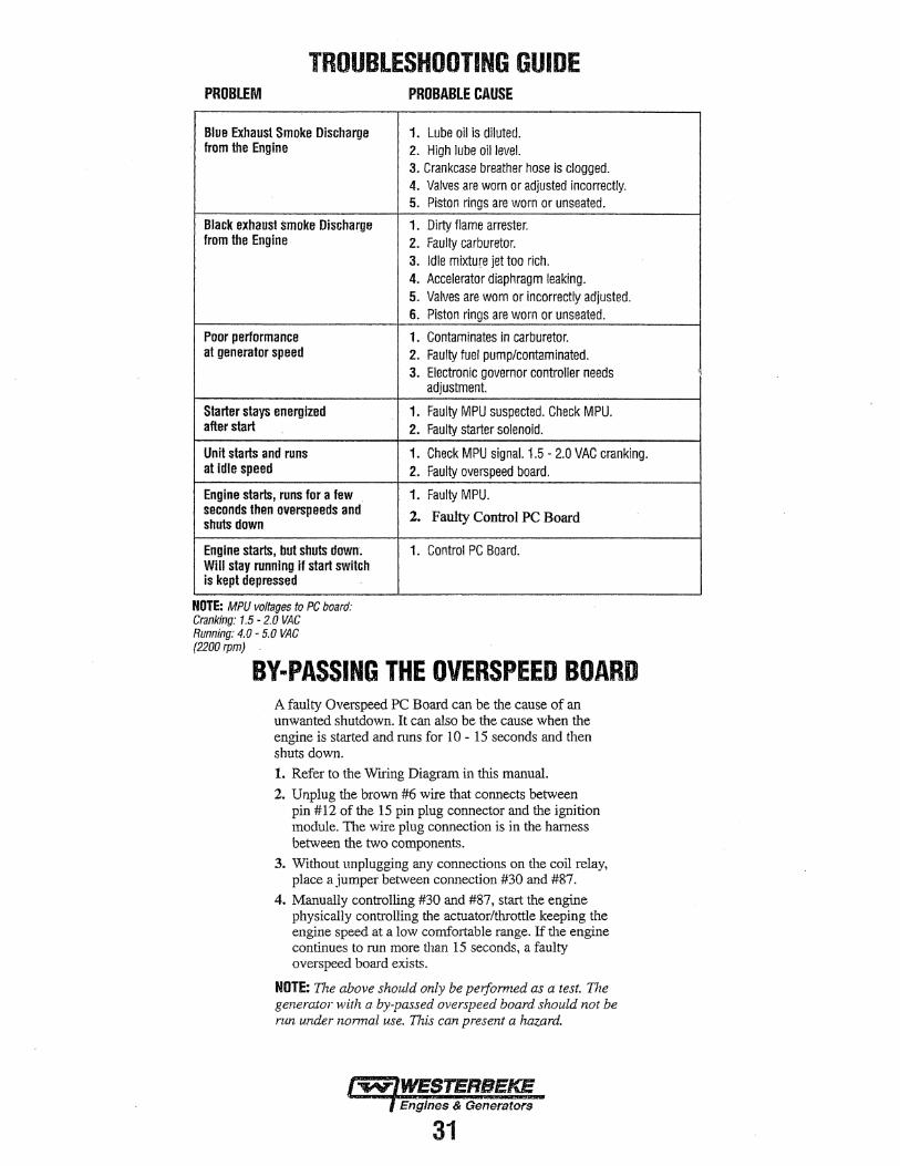
TROUBLESHOOTING GUIDE PROBLEM PROBABLE CAUSE
Blue EXhaust Smoke Discharge 1. Lube oil is diluted. from the Engine 2. High lube oil level.
3. Crankcase breather hose is clogged. 4. Valves are worn or adjusted incorrectly. 5. Piston rings are worn or unseated.
Black exhaust smoke Discharge 1. Dirty flame arrester. from the Engine 2. Faulty carburetor.
3. Idle mixture jet too rich. 4. Accelerator diaphragm leaking. 5. Valves are worn or incorrectly adjusted. 6. Piston rings are worn or unseated.
Poor performance 1. Contaminates in carburetor. at generator speed 2. Faulty fuel pump/contaminated.
3. Electronic governor controller needs adjustment.
Starter stays energized 1. Faulty MPU suspected. Check MPU. after start 2. Faulty starter solenoid.
Unit starts and runs 1. Check MPU signal. 1.5 - 2.0 VAC cranking. at idle speed 2. Faulty overspeed board.
Engine starts, runs for a few 1. Faulty MPU. seconds then overspeeds and 2. Faulty Control PC Board shuts down
Engine starts, but shuts down. 1. Control PC Board. Will stay running if start switch is kept depressed
NOTE: MPU voltages to PC board: Cranking: 1.5 - 2.0 VAC Running: 4.0 - 5.0 VAC (2200rpm)
BY-PASSING THE OVERSPEED BOARD A faulty Overspeed PC Board can be the cause of an unwanted shutdown. It can also be the cause when the engine is started and runs for 10 - 15 seconds and then shuts down.
1. Refer to the Wiring Diagram in this manual.
2. Unplug the brown #6 wire that connects between pin #12 of the 15 pin plug connector and the ignition module. The wire plug connection is in the harness between the two components.
3. Without unplugging any connections on the coil relay, place a jumper between connection #30 and #87.
4. Manually controlling #30 and #87, start the engine physically controlling the actuator/throttle keeping the engine speed at a low comfortable range. If the engine continues to run more than 15 seconds, a faulty overspeed board exists.
NOTE: 17ie above should only be pe1f ormed as a test. 17ie generator with a by-passed overspeed board should not be nm under nonnal use. 17iis can present a hazard.
31
!

MAG.PICK-UP 950-10000
SH\E:LO(D
n T4
GENERATOR WIRING DIAGRAM RESISTANCE VALUES IN OHMS IN BLACK ITALIC
12.5 • 18.511 1.4 • 2. tfl ~-~EXCITER COIL
...... ~·'~·~s~L·~'~···~·-----~f!!AG.CO_t_l--1,....,-=>-··~"'~·~a~LK~I~··~·------------. ---~f~-----c:J i 16 YH/REQ
1t1s au tl6 BLK
r 1'18 - 222 fl IGNlllON PULSER COIL MODULE
ft,. R(D/ HT ~---+--~ ~~~~-------~-----+-----+--~
~~ 12.5 - 18.Sfl EXCITER COIL
CARBURETOR SOLENOIO
ltl6 AEO
IGNITION COIL
0.27 • 0.41{) ~ ALT. COIL
JIG REDfVIO
VOLTAGE REGULATOR
RESISTANCE VALUES IN OHMS MAGNETO COIL.. ................... 1.4 • 2.1
EXCITER COIL ....................... 12.5·18.8
PULSER COIL ........................ 148 • 22·2
ALTERNATOR COIL .................. 0.27 • 0.41
IGNITION COIL.. ..................... 0.26 - 0.35 (Primary)
MAGNETIC PICK-UP •.•..••.••••••• 950-1000. START SOLENOID ................... 4.7 HIGH TENSION LEADS .............. 6.800·10.DOO
DE·RICH VALVE _ _. .................. 20
ACTUATOR ........................... 3.0 ·3.1
NOlE: TESTER USED· FLUKE MULTIMETER TOLERANCE :l: 20%
BATTERY I Z VDC
ll8 Blk
STARTER SOLENOID
4.7fl START SOLENOfO
FUSE'. IOA
R£MOT£ SHUTDOWN TERMINAL UNIT CAN I: POSITIVE !+I RESTART 2: AUX. SHUTDOWN
UNIT CAN 3: ENERGEHCY STOP NOT RESORT 4: GROUND C·l .
JUMPER< SI MUST 6( REMOVED
OVERSPEED PC BOARD (PN #0453'17) CONTROL PC BOARD (PN # 045369)
TERMlllA.LS 1 I\ 2 ARE FOR "FlRESOY" CONNECTION
.TERMINALS 3 & 4 ARE FOR "EMERGENCY STOP SWITCH"
ti S GRN/REO
COIL RELAY
ENGINE CONNECTOR
CONTROL PC BOARD
116 REO/\'IHT
t 16 BLK
t 16 ORG
# 16 YEL
# 16 R£
t 16 GRN
PANEL/REMOTE CONNECTOR
CONTROL PC BOARD
PART NUMBERS: REMOTE STOP/START PANEL #048056 PANEL EXTENSION HARNESS 15FT #048200, 30 FT #048201
l
+
GREEN TO STARTER GROUND RED ISOLATION POST RED ISOLATION POST
220V·50HZ WHITE 0 0 GREEN
CONNECTIONS FOR Q
230V50Hz 0 AC OUTPUT CONNECTIONS 120V 60Hz
L N LOAD
Engines & Generators
32
SPARK PLUGS
OIL PRESS SWITCH
It WA~T~
EXHAUST TEMPERA11JRE
SWITCH
~ ..
HOUR METER
START/STOP SWITCH

GENERATOR INFORMATION
USE OF ELECTRIC MOTORS The power required to start an electric motor is considerably more than is required to keep it running after it is started. Some motors require much more current to strut them than others. Split-phase (AC) motors require more cmTent to start, under similar circumstances, than other types. They are commonly used on easy-starting loads, such as washing machines, or where loads are applied after the motor is started, .such as small power tools. Because they require 5 to 7 times as much current to start as to run, their use should be avoided, whenever possible, if the electric motor is to be driven by a small generator. Capacitor and repulsioninduction motors require from 2 to 4 times as much current to start as to run. The current required to start any motor varies with the load connected to-it. An electric motor connected to an air compressor, for example, will require more current than a motor to which no load is connected.
In general, the current required to start 115-Volt motors connected to medium starting loads will be approximately as follows:
MOTOR SIZE AMPS FOR AMPS FOR (HP) RUNNING STARTING
(AMPERES) (AMPERES) 1/6 3.2 6.4 to 22.4~ -1/4 4.6 ' 9.2 to 32.2* 1/3 5.2 10.4 to 72.8 * 1/2 7.2 14.4 to 29.2* 3/4 10.2 20.4 to 40.8* 1 13 26 to 52 '
*NOTE: In the above table the maximum Amps for Starting is more for some small motors than for larger ones. The reason for this is that the hardest starting types (split-phase) are not made in larger sizes.
Because the heavy surge of current needed for starting motors is required for only an instant, the generator will not be damaged if it can bring the motor up to speed in a few seconds. If difficulty is experienced in starting motors, turn off all other electrical loads and, if possible, reduce the load on the electric motor.
Required Operating Speed Run the generator first with no load applied, then at half the generator's capacity, and finally loaded to its full capacity as indicted on the generators data plate. The output voltage should be checked periodically to ensure proper operation of the generating plant and the appliances it supplies. To monitor voltage and load, check it with a portable meter and amp probe.
Generator Maintenance Maintaining reasonable cleanliness is important. Connections of terminal boards and rectifiers may become corroded, and insulation surfaces may start conducting if salts, dust, engine exhaust, carbon, etc. are allowed to build up. Clogged ventilation openings may cause excessive heating and reduced life of windings.
In addition to periodic cleaning, the generator should be inspected for tightness of all connections, evidence of overheated terminals andloose or damaged wires.
Generator Failure BPMGModel
Should a failure occur in a permanent magnet - BPMG Model (no AC output). do not attempt to make repairs or adjustments to the generator. The generator is maintenance free. Contact you WESTERBEKE dealer or distributor.
NOTE: It would be important first to inspect the pulley and drive belt under the generator base frame.
BC Model
Refer to BCG Troubleshooting in the following pages.
Engines & Generators
33

BCG/BPMG DESCRIPTION and .TROUBLESHOOTING - . • I ' . • . '
REFER ALSO TO THE SPECIFICATION PAGE
BRUSHLESS CAPACITOR GENERATOR (BCG)
Engine RPM at 2200 generator turns at 3600 (60Hz) 3000 (50Hz) 60Hz 120 Volts/25 Amps 50Hz 230 Volts/13 Amps
NOTE: Refer to the following page for the BCG Internal Wiring Schematic and BCG Winding Resistances.
DIAGRAMS ARE FOR BOTH MODELS
RED ISOLATIOU POST
WHlTE N
120V/60Hz
BLACK
0 AC CIRCUIT BREAKER
BCG/BPMG AC OUTPUT CONNECTIONS DIAGRAM l1
GREEN TO STARTERllROIJND
WHITE Atf>-----~ -"'<:rf-----,-~
BLACK 220V·50HZ
230V/50Hz AC
o CIRCUIT BREAKER
PERMANENT MAGNET IR GENERATOR (BPMG) Engine RPM at 2200 generator turns at 3600 (60Hz) 3000 (50Hz) 60Hz 120 Volts/25 Amps 50Hz 230 Volts/13 Amps
TROUBLESHOOTING CHART (BCG) CAUSE FAULT
No AC Output Voltage
Residual Voltage Line - Neutral at No Load
Low AC Output Voltage 60 - 100 Volts
1. Shorted Stator. 2. Open Stator. 3. Shorted Rotor Diode. 4. Shorted Rotor Thermister. 5. Shorted Rotor Capacitor. 6. Open Rotor Diode.
1. Faulty Capacitor. 2. Open Exciter Winding. 3. Shorted Exciter Winding.
1. Faulty Rotor Diode. 2. Faulty Rotor Winding. 3. Faulty Ex~iter Capacitor.
AC Voltage Drop with 1. Faulty Rotor Diode. Inductive Load 2. Faulty Exciter Capacitor.
3. Amperage Overload.
Refer to the following page for the BCG Internal Wiring Schematic and the BCG Winding Resistances.
TROUBLESHOOTING CHART (BPMG) CAUSE FAULT
No AC Output Voltage 1. Shorted Stator Winding. Open Stator Winding.
Low AC Output 1. Faulty Rotor. Voltage 60 - 100 Volts
Vortage Drop 1. Generator Overload. Under load
WINDING RESISTANCE (Measured at 20°C/68°F) PM (Permanent Magnet) stator winding resistance 0.4 ohm he1tz model resistance is measured between line and neutral. 50 hertz models is 0.8 ohm.
NOTE: The permanent magnet style generator can not be disassembled. If an electrical fault should occur, the generator must be replaced.
NOTE: It would be important to inspect the pulley and drive belt under the generator base frame.
Engines & Generators
34

BCGBACKEND COMPONENTS (TOP VIEW)
. GROOND~ · .
.CAPACITOR
IBESE COMPONENTS ARE LOCATED ON THE
. ROTOR .
. AC TERMINAL BLOCK
-$;i WllllJINtl RESISTAflCE (Measured at 200C/68'F) . .
60 Hertz Models : Stator Winding 0.93 Ohm/winding. 50 Hertz Models : Stator Winding 1.35 Ohm/winding. Rotor Winding - 4~0 Ohm Rotor Winding - 4.0 Ohm Excitor Winding - 2.0 Qhm Excitor Winding .. 2.5 Ohm Capacitor Rating - 34 uF Capacitor Rating - 31.55 uF
BCG INTERNAL.WIRING DIAGRAM ·GREEN
ROTOR STATOR ·YELLOW EXCITOR OR
I BROWN I •N.WHITE WHITE
I - . ri '12ov· 1· - . • THERMISTER . I
!i RED RED
luiA K.
61~ ' .
I :1
, BLACK :I I BLUE :I CAPACITOR
;1
,I! ' . '' ·. .
BY-PASSING THE OVERSPEED BOARD An unwanted shutdown or if the engine runs 10-15 seconds and then shuts down can be caused by a faulty over-speed board. 1. Refer to the Wtting Diagram in this manual. 2. Unplug the brown #6 wire that connects between pin #12
of the 15 pin plug connector and the ignition module. The wire plug connection is in the harness between the two components.
3. Without unplugging any connections on the coil relay, · place a jumper between connection #30 and #87.
4. Manually controlling #30 and #87, start the engine physically controlling the actuator/throttle keeping the engine speed at a low comfortable range. H the engine continues to run more than 15 seconds, a faulty overspeed board exists.
NOTE: The above should only be perfonned as a test. The generator with a by-passed overspeed board should not be run under nonnal use. This can present a hazard.
Engines & Generators
-35'

LAY-UP AND RECOMMISSIONING GENERAL Many owners rely on their boatyards to prepare their craft, including engines and generators, for lay-up during the off-season or for long periods of inactivity. Others prefer to accomplish lay-up preparation themselves. The procedures which follow will allow you to perform your own lay-up and recommissioning, or to use as a check list if others do the procedures. These procedures should afford your engine protection during a lay-up and also help familiarize you with the maintenance needs of your engine. If you have any questions regarding lay-up procedures, call your local servicing dealer; he will be more than willing to provide assistance.
ENGINE COOLING (Raw Water Cooled Models) If the engine will be out of commission for 3 months or more, the engine's cooling passages should be flushed with fresh water. Also the water pump(s) should be disassembled and the impellers stowed in a cool, dark area. Instructions for flushing the cooling system are shown on the next page.
LUBRICATION SYSTEM With the engine warm, drain all the lubricating oil from Qie oil sump. Remove and replace the oil filter and fill the sump with new oil. Use the correct grade of oil. refer to the ENGINE LUBRICATING OIL pages in this manual for the oil changing procedure. Run the engine and make sure there are no leaks.
A CAUTION: Do not leave the engine's old lubricating oil in the sump ovet the lay"'up period •. Lubricatlng·oil and combustion,deposits combine to produce hannful chemicals whicb can reduce the life of
· your engine's intemal parts.
INTAKE MANIFOLD Clean the filter screen in the flame arrester, and place a clean cloth lightly soaked in lube oil around the flame arrester to block any opening. Also place an oil-soaked cloth in the thru-hull exhaust port. Make note to remove cloths prior to start-up!
FUEL SYSTEM Top off your fuel tanks with unleaded ~oline of.~9 oc~e or higher. A fuel conditioner such as mann~ sta~il gasohne should be added. Change the element in your gasoline/water separator and clean the metal bowl. Re-install and make certain there are no leaks. Clean up any spilled fuel.
STARTER MOTOR Lubrication and cleaning of the starter drive pinion is advisable, the pinion is accessible when the flywheel cover is removed. Make sure the battery connections are shut off before attempting to remove the starter. Take care m properly replacing any electrical connections removed from the starter.
SPARES Lay-up time provid~ a good opportunity to inspect your WESTERBEKE engine to see if external items such as drive belts or coolant hoses need replacement. Check your basic spares kit and order items not on hand, or replace those items used during the lay-up, such as filters and zinc anodes. Refer to the SPARE PARTS section of this manual.
BATIERIES If batteries are to be left; on board during the lay-up period, make sure they are fully charged, and will ~~ that way, to prevent them from freezing. If there exists any doubt that the batteries will not remain fully charged, or that they will be subjected to severe environmental conditions, remove the batteries and store them in a warmer; more compatible environment.
Engines & Generators . - 36 .

· FLUSHING THE ENGINES COOLING SYSTE~ Engine flushing should be performed a minimum of at least t.W,ice per operating season, more often in those areas \Vhere the unit may not.be s1,1bjectto winter storage. Int?ose . locations where the unit is used year round, flushing the unit once every 4 months is recommended. This procedure is best accomplished by disconnecting the water intake hose from the vessel's thru-hull fitting. Insert the hose end into a large container of fresh water. Close the thru-hull intake valve before disconnecting the hose. Before starting the engine, remove the engine thermostat (replace the gasket and cover). This will ensure a full flow of water thru the engine. Re·install the thermostat once
Run the unit for 10 minutes or longer to adequately flush the cooling system. The fresh water will flush out the engine's water passages and exhaust lines: If the engine is being stored and there is a probability of freezing, flush the engine with fresh water and then prior to shutting the unit dowp. Substitute the fresh water supply with a concentrated antifreeze mixture and run this through the engine to provide freeze and corrosion protection for both the engine and exhaust system. When recommissioning, make certain the thru-hull intake valve is open so the engine will quickly receive cooling water.
flushing is complete. A NOTE: Prior to flushing the engine, inspect the coolant by- CAUTION: Do not connect an external fresh water pass hose and its attachment fittings to insure that there are supply directly to the engine's coaling system. This can no obstructions occurring in the fittings or the hose. cause naading of the engine resulting in internal Provide an external fresh water supply for the container to maintain the water level in the container while the unit is being i"ll:::r--,da~_ma ___ ige. v '----------------operated during the flushing process.
. . RAW WATER ALTER EXTERNAL FRESH {\ WATER SUPPLY
.RAW WATER PUMP
FRESHWATER
Engines & Generators
37
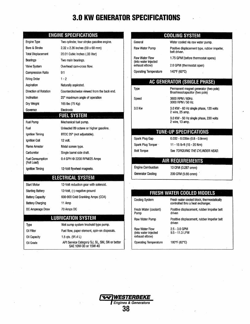
3.0 KW GENERATOR SPECIFICATIONS
ENGINE SPECIFICATIONS COOLING SYSTEM Engine Type
Bore & Stroke
Total Displacement
Beatings· ·
Valve System
Compression Ratio
Firing Order
Aspiration
Direction of Rotation
Inclination
Dry Weight
Governor
Fuel Pump
Fuel
Ignition Timing
Ignition Coil
Flame Arrester
Carburetor
Fuel Consumption (Full Load)
Ignition Timing
Start Motor
Starting Battery
Battery Capacity
Battery Charging
DC Amperage Draw
Type
Oil Filter
Oil Capacity
Oil Grade
Two cylinder. four str()ke gasoline engine.
2.32 x 2.36 inches (59 x 60 mm)
20.01 Cubic Inches (.33 liter)
Two main beatings.
Overhead cam-cross flow.
9:1
1 -2
Naturally aspirated.
Counterclockwise viewed from the back end.
25° maximum angle of operation
165 lbs (75 Kg)
Electronic
FUEL SYSTEM Mechanical fuel pump.
Unleaded 89 octane or higher gasoline.
BTDC 25° (not adjustable).
12 volt.
Metal screen type.
Single barrel side draft.
0.4 GPH @ 2200 RPM/25 Amps
12-Volt flywheel magneto.
ELECTRICAL SYSTEM 12-Volt reduction gear with solenoid.
12-Volt, (-)negative ground
600-900 Cold Cranking Amps (CCA)
11 Amp
70 Amps DC
LUBRICATION SYSTEM Wet sump system trochoid type pump.
Fuel flow, paper element. spin-on disposals.
1.5 qts. (91.4 L)
API Service Categor}' SJ, SL, SM, SN or better SAE 10W-30or15W-40
General
Raw Water Pump
Raw Water Flow (into water injected exhaust elbow)
Operating Temperature
Water cooled via raw water pump.
Positive displacement type, rubber impeller, belt driven.
1.75 GPM'(before thermostat opens)
2.0 GPM (thermostat open)
140°F (60°C)
AC GENERATOR (SINGLE PHASE) Type
Speed
3.0Kw
Permanent magnet generator (two pole) Brushless/capacitor (two pole)
3600 RPM / 60Hz. 3000 RPM I 50 Hz.
3.0 KW - 60 Hz single phase, 120 volts 2 wire, 25 amp.
3.0 KW - 50 Hz single phase, 230 volts 2 wire, 13 amp.
TUNE-UP SPECIFICATIONS Spark Plug Gap
Spark Plug Torque
Bolt Torque
0.032 - 0.035in (0.8 - 0.9mm)
11 -15 lb-ft (15- 20 Nm)
See TORQUING THE CYLINDER HEAD.
AIR REQUIREMENTS Engine Combustion
Generator Cooling
13 CFM (0.287 cmm)
200 CFM (5.66 cmm) ·
FRESH WATER COOLED MODELS Cooling System
Fresh Water (coolant) Pump
Raw Water Pump
Raw Water Row (into water injected exhaust elbow)
Operating Temperature
Fresh water cooled block, thermostatically controlled thru a heat exchanger.
Positive displacement. rubber impeller belt driven
Positive displacement, rubber impeller belt driven
2.5-3.0GPM 9.5 - 11.3 LPM
180°F (82°C)
Engines & Generators
38

DECIMAL TO METRIC EQUIVALENT CHART
Fractions of Decimal (in.) Metric (mm)
Fractions of Decimal (in.) Metric (mm)
an inch an Inch
1/64 0.015625 0.39688 33/64 0.515625 13.09687
1/32 0.03125 0.79375 17/32 0.53125 13.49375
3/64 0.046875 1.19062 35/64 0.546875 13.89062
1/16 0.0625 1.58750 9/16 0.5625 14.28750
5/64 0.078125 1.98437 37/64 0.578125 14.68437
3/32 0.09375 2.38125 19/32 0.59375 15.08125
7164 0.109375 2.77812 39/64 0.609375 15.47812
1/8 0.125 3.175 5/8 0.625 15.87500
9/64 0.140625 3.57187 41/64 0.640625 16.27187
5/32 0.15625 3.96875 21/32 ' 0.65625 16.66875
11/64 0.171875 4.36562 43/64 0.671875 17.06562
3/16 0.1875 4.76250 11/16 0.6875 17.46250
13/64 0.203125 5.15937 45164 0.703125 17.85937
7/32 0.21875 5.55625 23/32 0.71875 18.25625
15/64 0.234375 5.95312 47164 0.734375 18~65312 . ' 1/4 0.250 6.35000 3/4 0.750 19.05000.
17/64 0.265625 6.74687 49/64 0.765625 ·19.44687
9/32 0.28125 7.14375 25/32 0.78125 19.84375
19/64 0.296875 7.54062 51/64 0.796875 20.24062
5/16 0.3125 7.93750 13/16 0.8125 20.63750
21/64 0.328125 8.33437 53/64 . 0.828125 21.03437
11/32 0.34375 8.73125 27/32 0.84375 21.43125
23/64 .0.359375 9.12812 55/64 0.859375 21.82812
3/8 0.375 9.52500 7/8 0.875 22.22500 ' 25/64 0.390625 9.92187 57164 0.890625 22.62187
·13/32 0.40625 10.31875 29/32 0.90625 23.01875
27/64 0.421875 10.71562 59/64 0.921875 23.41562
7/16 0.4375 11.11250 15/16 0.9375 23.81250
29/64 0.453125 11.50937 61/64 0.953125 24.20937
15/32 0.46875 11.90625 31/32 0.96875 24.60625
31/64 0.484375 12.30312 63/64 0.984375 25.00312
,1/2 0.500 12.70000 1 1.00 25.40000
Engines & Generators
39

SUGGESTED SPARE PARTS WESTERBEKE MARINE GASOLINE GENERATORS
CONTACT YOUR WESTERBEKE DEALER FOR SUGGESTIONS AND ADDITIONAL INFORMATION
SPARK PLUGS
WATER PUMP IMPEllERS, O·RINGS · AND GLYCERIN TUBE.
THERMOSTAT ·AND GASKET
WESTERBEKE ALSO RECOMMENDS HAVING ENOUGH OIL ON-BOARD FOR AT LEAST ONE OIL CHANGE
10AfuSE (ONSIDEOF ~
CONTROL PANELF
ENGINE BELT 'WATER PUMP .BELT
.,GASOLINE I
FUELJWATER. : FILTERS
'ZINC . ANODE.
HEA EXCHANGER END GASK~T A.ND o-mNG
___ ___;_ ____ SPARE PARTS KITS-----'--------WESTERBEKE also offers two Spare Parts·Kits, each packaged in a rugged hinged toolbox. Kit A includes the basic spares. Kit B is for more extensive off-shore cruising.
KIT A IMPELLER KIT OIL FILTER GENERATOR DRIVE BELT ZINC ANODES WITH GASKET SPARK PLUGS 20A FUSE WATER PUMP BELT FUEL FILTER KIT 10A FUSE HEAT EXCHANGER ZINC
Engines & Generators
40
KIT B · IMPELLER KIT OIL FILTER GENERATOR DRIVE BELT ZINC ANODES WITH GASKET SPARK PLUGS 20A FUSE WATER PUMP BELT FUEL FILTER KIT 10A FUSE COMPLETE GASKET SET THERMOSTAT KIT WATER PUMP REPAIR KIT · OIL PRESSURE SWITCH HEAT EXCHANGER ZINC

Engines & Generators
SERVICE BULLETIN
DATE: __ 24-Apr-1_5 __ BULLETIN NUMBER: ----276
SUB.JECT: Generator Drive Belt Performance
MODELS AFFECTED: 3.5 SBCG and 3.0 BCG Gasoline Generators
DETAIL: Generator drive belt life performance improvements include a belt tension adjustment change, the addition of a spring spacer, and a new idler pulley. 3.5 SBCG generators produced on or after manufacturing date code OD (April 2015) will have these changes. Changes made are enhancements, modification to existing products in the field is not covered under warranty.
Manufacturing of new products includes. for optimum belt break in, adjusting the belt to a dimension of 1" in our assembly process as illustrated below. After the first hour of run time if necessary, it is adjusted again to 1" prior to releasing the unit for shipment.
Important Note: Maximum performance of the drive belt and prevention of potential failure due to incorrect tension requires the belt be to adjusted to 1" at the recommended 50 hour maintenance service.
Generator drive belts for regular maintenance replacement (part numbers remain the same) wlll be sold as a k.it with instructions that includes the required spring spacer. Replacing the pulley is not required. Initial adjustment of the belt with the spacer installed is 1 ". After running the unit for 1 hour. varying AC loads in the process, the belt must be adjusted again to 1". After 50 hours run time, or during the next scheduled service, inspection and adjustment to 1" is required to ensure proper belt tension.
Add 1 !8" Spacer Here
WEST~RB[!(E COR!"OR ~T>ON
My!J?~, St0riDi~,h lndu"'.iri~_·d P,;1r'<. JSn !o11n H;:w1cocf< Ro;id, T;:iunton, f\11/\ 02780-73:19 1) Tel: 508.823.7677 1t F;.)'('. ::io8.88<'l.9(\~p,
www.westerbeke.com


Engines & Generators
125015-2018