Operators manual Models - YAZOO/ · PDF fileOperators manual ZVKH61271 ZVKH72271 ZVKHL61231...
30
Operators manual ZVKH61271 ZVKH72271 ZVKHL61231 ZVKW52251 ZVKW61251 ZVHO61241 Models: Please read these instructions carefully and make sure you understand them before using the machine. MANUAL NO. 109206 REV. IR (09/01/03) For Serial No. 033600000 & Higher
Transcript of Operators manual Models - YAZOO/ · PDF fileOperators manual ZVKH61271 ZVKH72271 ZVKHL61231...

Operators manualZVKH61271ZVKH72271ZVKHL61231ZVKW52251ZVKW61251ZVHO61241
Models:
Please read these instructions carefully and makesure you understand them before using the machine.
MANUAL NO. 109206 REV. IR (09/01/03)
For Serial No. 033600000 & Higher

2
©2003 Yazoo/Kees Power Equipment. All Rights Reserved.Beatrice, NE. Printed in U.S.A.

3
CONTENTS
INTRODUCTION .................................. 4-5
SYMBOLS & DECALS ......................... 6
SAFETY INSTRUCTIONS.................... 7
General use and safety rules ...... 7-8
Driving on slopes ........................ 9
Children safety............................ 10
Service safety ............................. 10-12
Transportation ............................ 12
PRESENTATION................................... 13
SETUP AND ADJUSTMENTS .............. 14
Setup .......................................... 14
Cutting height ............................. 14
Mower deck leveling ................... 15
Throttle lever tension .................. 15
Reverse spring detent adj. .......... 15
Park brake adj. ............................ 16
Motion control lever adj. .............. 16
OPERATING INSTRUCTIONS ............ 17
Starting and operation ................. 17
Controls ...................................... 17-19
MAINTENANCE .................................... 19
Engine oil .................................... 19
Mower blades ............................. 19
Safety interlock system .............. 19
Cutter housings .......................... 19
Hardware .................................... 20
Air filter ........................................ 20
Hydraulic system ........................ 20
Deck belt .................................... 20
Pump belt ................................... 21
Lubrication .................................. 21
Tire pressure .............................. 21
Caster wheels ............................ 21
Fuel filter ..................................... 21
Winter storage ............................ 21
TORQUE SPECIFICATIONS ............... 22
MAINTENANCE SCHEDULE ............... 23
TROUBLE SHOOTING ........................ 24
WIRING DIAGRAMS ............................. 25-28

4
Introduction
Congratulations
Thank you for purchasing a Yazoo/Kees ride-on mower. This machine is built for the greatest effi-ciency and rapid mowing of large areas. Convenient controls and a hydrostatic transmission regu-lated by steering levers also contribute to the machine’s performance.
This manual is a valuable document. Following the instructions (use, service, maintenance, etc.)can considerably increase the life-span of your machine and even increase its resale value.
If you sell your machine, be sure to give the operator’s manual to the new owner.
The final chapter of this operator’s manual comprises a Service Journal. Ensure that service andrepair work is documented. A well kept service journal reduces service costs of the season-basedmaintenance and affects the machine’s resale value. Take the operator’s manual along when themachine is left at the service center for service.
General
In this operator’s manual, left and right, backward and forward are used in relation to the machine’snormal driving direction.
Driving and Transport on Public Roads
Check applicable road traffic regulations before driving and transporting on public roads. If themachine is transported, you should always use approved fastening equipment and ensure that themachine is well anchored.
Operating
This machine is constructed only for mowing grass on lawns and other free and even ground with-out obstacles such as stones, tree stubs, etc. The machine can also be used for other tasks whenequipped with special accessories provided by the manufacturer, for which the operating instruc-tions are provided in conjunction with delivery. All other types of use are incorrect. Themanufacturer’s directions concerning operation, maintenance, and repairs must be carefully fol-lowed.
The machine must only be operated, maintained, and repaired by persons that are familiar with themachine’s special characteristics and who are well versed in the safety instructions.
Accident prevention regulations, other general safety regulations, occupational safety rules, andtraffic regulations must be followed without fail.
Unauthorized modifications to the design of the machine may absolve the manufacturer from liabilityfor any resulting personal injury or property damage.
INTRODUCTION

5
INTRODUCTIONGood ServiceYazoo/Kees products are sold all over the world and only in specialized retail stores with completeservice. This ensures that you as a customer receive only the best support and service. Before theproduct is delivered, the machine has, for example, been inspected and adjusted by your retailer,see the certificate in the Service Journal in this operator’s manual.
When you need spare parts or support in service questions, warranty issues, etc., please consultthe following professional:
This Operator’s Manual belongs to themachine with manufacturing number:
Engine Transmission
Manufacturing Number
The machine’s manufacturing number can be found on the printed decal affixed to the left side of theframe under the seat.
• The machine’s type designation (I.D.).• The manufacturer’s type number (Model).• The machine’s serial number (Serial no.)
Please state the type designation and serial number when ordering spare parts.
The engine’s manufacturing number is stated on a decal. This is placed on the right side on the topof the engine.
• The engine’s serial number (E/NO).• The engine’s type designation (Code).
Please state these when ordering spare parts.
The hydraulic pump’s manufacturing number is stated on a barcode decal affixed to the left side ofthe pump housing. The plate states:
• The pump’s type designation.• The pump’s serial number.
The hydraulic motor’s manufacturing number is stated on a round metal plate. This is placed on thegable inside the motor. The plate states:
• The hydraulic motor’s type designation and design version.• The hydraulic motor’s serial number.

6
SYMBOLS AND DECALS
Symbols and DecalsThese symbols are found on the machine and in the operator’s manual.Study them carefully so that you know what they mean.
WARNING!Xxxxxxx xxxx xxxxxxxx xxx xXxxxx xxxxxx xx.xx xxxxxxxx xxxxx xxx xx.
Used in this publication to notify the reader of a risk of personal injury, particularly if the readershould neglect to follow instructions given in the manual.
IMPORTANT INFORMATIONXxxxxxx xxxx xxxxxxxx xxx xxxxxxx xxxxxx xx.
Used in this publication to notify the reader of a risk of material damage, particularly if the readershould neglect to follow instructions given in the manual. Used also when there is a potential formisuse or misassembly.
R NReverse Neutral Fast Slow
Fuel
Ignition
Stop Run Start WarningDangerCaution
Parking brake
Do not stand here
Warning! Rotatingblades, keep away fromthe discharge deck Do not touch rotating parts
Battery acid is corrosive,explosive, and flammable
Use on a slope no greaterthan 10°.
Nopassengers
Careful goingforward, watchfor other people.
Careful backingup, watch forother people. Shut off engine and remove key before
performing any maintenace or repair work.
ReadOperatorsManual.
Whole bodyexposure tothrown objects. Severing of fingers and toes.
Do not openor removesafety shieldswhile engineis running.
Keep a safedistance fromthe machine.

7
SAFETY INSTRUCTIONSSafety InstructionsThese instructions are for your safety. Read them carefully.
WARNING!This symbol means that important safety instructions need to be emphasized. Itconcerns your safety.
General Use• Read all instructions in this operator’s manual
and on the machine before starting it. Ensurethat you understand them and then abide bythem.
• Learn how to use the machine and its con-trols safely and learn how to stop quickly. Alsolearn to recognize the safety decals.
• Only allow the machine to be used by adultswho are familiar with its use.
• Make sure nobody else is in the vicinity of themachine when you start the engine, engagethe drive, or run the machine.
• Make sure animals and people maintain a safedistance from the machine.
• Stop the machine if someone enters the workarea.
• Clear the area of objects such as stones, toys,steel wire, etc. that may become caught inthe blades and thrown out.
• Beware of the discharge deck and do not pointit at any one. Do not use the machine withoutthe discharge deck in place.
• Stop the engine and prevent it from startingbefore you clean the discharge deck.
• Remember that the operator is responsiblefor dangers or accidents.
• Never take passengers. The machine is onlyintended for use by one person.
• Always look down and behind before and dur-ing reversing maneuvers. Keep a look out forboth large and small obstacles.
• Slow down before turning.
• Shut down the blades when not mowing.
8011-512
Read the operator’s manual before starting the machine.
8011-513Clear the area of objects before mowing.
8011-520Never take passengers.

8
SAFETY INSTRUCTIONS• Be careful when rounding fixed objects, so that
the blades do not hit them. Never drive overforeign objects.
• Only use the machine in daylight or in otherwell-lit conditions. Keep the machine a safedistance from holes or other irregularities inthe ground. Pay attention to other possiblerisks.
• Never use the machine if you are tired, if youhave consumed alcohol, or if you are takingother drugs or medication that can affect yourvision, judgement, or coordination.
• Beware of traffic when working near or cross-ing a road.
• Never leave the machine unsupervised withthe engine running. Always shut down theblades, pull back the parking brake, stop theengine, and remove the ignition key beforeleaving the machine.
• Never allow children or other persons nottrained in the use of the machine to use orservice it. Local laws may regulate the age ofthe user.
Engine exhaust and certain vehiclecomponents contain or emit chemi-cals considered to cause cancer,birth defects, or other reproductivesystem damage. The engine ex-haust contains carbon monoxide,which is colorless, poisonous gas.Do not use the machine in en-closed spaces.
WARNING!
WARNING!When using the machine, approved personal protective equipment shall be used.Personal protective equipment cannot eliminate the risk of injury but it will reducethe degree of injury if an accident does happen. Ask your retailer for help in choosingthe right equipment.
• Make sure that you have first aid equipmentclose at hand when using the machine.
• Never use the machine when barefoot. Alwayswear protective shoes or boots, preferably withsteel toecaps.
• Always wear approved protective glasses ora full visor when assembling or driving.
• Never wear loose clothing that can get caughtin moving parts.
8011-292Personal protective equipment.
8011-518Keep children away from the work area.

9
6003-004
Mow up and down, not side-to-side.
Driving on SlopesSAFETY INSTRUCTIONS
Driving on slopes is one of the operations wherethe risk is greatest that the driver will lose controlor the machine will tip over, which can result inserious injury or death. All slopes require extracaution. If you cannot reverse up a slope or if feelunsure, do not mow the slope.
Do as follows:• Remove obstacles such as stones, tree
branches, etc.
• Mow up and down, not side-to-side.• Never drive the rider on terrain that slopes
more than 10°.
• Avoid starting or stopping on a slope, If thetires begin to slip, shut down the blades anddrive slowly down the slope.
• Always drive evenly and slowly on slopes.
• Make no sudden changes in speed or direc-tion.
• Avoid unnecessary turns on slopes, and if itproves necessary, turn slowly and graduallydownward, if possible.
• Watch out for and avoid driving over furrows,holes, and bumps. On uneven terrain, themachine can tip more easily. Long grass canhide obstacles.
• Drive slowly. Use small movements of thesteering controls.
• Be extra cautious with any additional equip-ment, which can alter the machine’s stability.
• Do not mow near verges, ditches, or banks.The machine can suddenly spin around if awheel goes over the edge of a drop or ditch,or if an edge gives way.
• Do not mow wet grass. It is slippery, and thetires can lose their grip, so that the machineslides.
• Try not to stabilize the machine by putting afoot on the ground.
• When cleaning the chassis, the machine maynever be driven near verges or ditches.
8011-519
Be extra cautious when driving on slopes.

10
SAFETY INSTRUCTIONSChildren:• Serious accidents may occur if you fail to be
on guard for children in the vicinity of the ma-chine. Children are often attracted to the ma-chine and mowing work. Never assume thatchildren will stay put where you last saw them.
• Keep children away from the mowing area andunder close supervision by another adult.
• Keep an eye out and shut off the machine ifchildren enter the work area.
• Before and during a reversing maneuver, lookbackward and downward for small children.
• Never allow a child to ride with you. They canfall off and injure themselves seriously or pre-vent risk-free maneuvering of the machine.
• Never allow children to operate the machine.
• Be particularly cautious near corners, bushes,trees, or other objects that block your view.
WARNING!The engine must not be started when the driver’s floor plate or any protectiveplate for the mower deck’s drive belt is removed.
• Stop the engine. Prevent the engine from start-ing by removing the ignition key before mak-ing any adjustments or performing mainte-nance.
• Never fill the fuel tank indoors.
• Fuel and fuel fumes are poisonous and ex-tremely flammable. Be especially cautiouswhen handling fuel, as carelessness can re-sult in personal injury or fire.
• Only store fuel in containers approved for thepurpose.
• Never remove the fuel tank cap and never fillthe fuel tank while the engine is running.
Maintenance:
8011-517
Never allow children to operate the machine.
8011-516
Never fill the fuel tank indoors.

11
• Allow the engine to cool before refueling. Donot smoke. Do not fill fuel in the vicinity ofsparks or open flames.
• If leaks arise in the fuel system, the enginemust not be started until the problem has beenresolved.
• Store the machine and fuel in such a way thatthere is no risk of leaking fuel or fuel vaporleading to damages.
• Check the fuel level before each use and leavespace for the fuel to expand, because the heatfrom the engine and the sun may otherwisecause the fuel to expand and overflow.
• Avoid overfilling. If you spill fuel on the machine,wipe up the spill and wait until it has evapo-rated before starting the engine. If you havespilled fuel on your clothing, change yourclothing.
• Allow the machine to cool before taking anyactions in the engine compartment.
• Be very careful when handling battery acid.Acid on skin can cause serious corrosiveburns. If you spill battery acid on your skin,rinse immediately with water.
• Acid in the eyes can cause blindness, con-tact a doctor immediately.
• Be careful when servicing the battery. Explo-sive gases form in the battery. Never performmaintenance on the battery when smoking ornear open flames or sparks. The battery canexplode and cause serious injury/damage.
• Ensure that nuts and bolts, especially the fas-tening bolts for the blade attachments, areproperly tightened and that the equipment isin good condition.
• Do not modify safety equipment. Check regu-larly to be sure it works properly. The machinemust not be driven with defective or un-mounted protective plates, protective cowl-ings, safety switches, or other protective de-vices.
• Do not change the settings of governors andavoid running the engine with overly high en-gine speed. If you run the engine too fast, yourisk damaging the machine components.
The engine, the exhaust system,and the hydraulic system’s compo-nents become very warm duringoperation.Risk for burns if touched.
WARNING!
The battery contains lead and leadcompounds, chemicals that areconsidered to cause cancer, birthdefects, and other reproductivesystem damage.Wash your hands after touching thebattery.
WARNING!
8011-563
Do not smoke when performing maintenance on thebattery. The battery can explode and cause seriousinjury/damage.
SAFETY INSTRUCTIONS
12
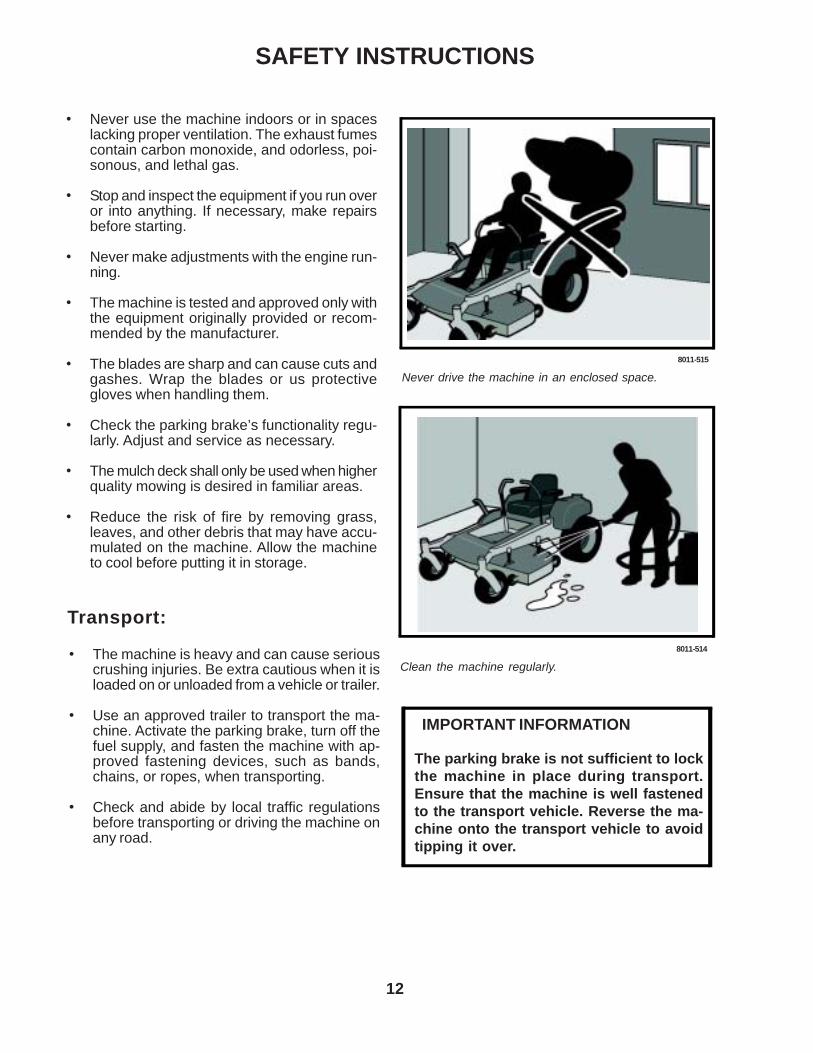
• Never use the machine indoors or in spaceslacking proper ventilation. The exhaust fumescontain carbon monoxide, and odorless, poi-sonous, and lethal gas.
• Stop and inspect the equipment if you run overor into anything. If necessary, make repairsbefore starting.
• Never make adjustments with the engine run-ning.
• The machine is tested and approved only withthe equipment originally provided or recom-mended by the manufacturer.
• The blades are sharp and can cause cuts andgashes. Wrap the blades or us protectivegloves when handling them.
• Check the parking brake’s functionality regu-larly. Adjust and service as necessary.
• The mulch deck shall only be used when higherquality mowing is desired in familiar areas.
• Reduce the risk of fire by removing grass,leaves, and other debris that may have accu-mulated on the machine. Allow the machineto cool before putting it in storage.
SAFETY INSTRUCTIONS
Transport:
• The machine is heavy and can cause seriouscrushing injuries. Be extra cautious when it isloaded on or unloaded from a vehicle or trailer.
• Use an approved trailer to transport the ma-chine. Activate the parking brake, turn off thefuel supply, and fasten the machine with ap-proved fastening devices, such as bands,chains, or ropes, when transporting.
• Check and abide by local traffic regulationsbefore transporting or driving the machine onany road.
8011-515
Never drive the machine in an enclosed space.
8011-514
Clean the machine regularly.
The parking brake is not sufficient to lockthe machine in place during transport.Ensure that the machine is well fastenedto the transport vehicle. Reverse the ma-chine onto the transport vehicle to avoidtipping it over.
IMPORTANT INFORMATION

13
PRESENTATION
FUEL CAP
MOTION CONTROLLEVERS
PARKINGBRAKE
DECK LIFTLEVER
FOOTPLATE
KEY SWITCH
BLADEENGAGEMENTSWITCH
THROTTLE
Presentation
Thank you for buying a YAZOO/KEES! Beforeoperating your new mower, read, understandand follow the safety instructions and otherdirections in this manual.
Lawnmowers and all power equipment, can bepotentially dangerous if used improperly. Safetyrequires good judgement, careful use in accor-dance with these instructions and commonsense.
HOURMETER

14
SETUP AND ADJUSTMENTSWARNING: No settings or adjustments areto be made unless: Engine is stopped, keyhas been removed, park brake is on andbattery cable removed from battery.
SetupUncrate machine.
Mount rear drive wheels using the lug nutsinstalled on the hubs.
Check the tire pressure in all four tires. All tiresshould be 15 psi.
Remove top bolt in control arm and loosenbottom bolt, rotate the control levers to theupright position. Align the levers so they areeven in the neutral position. Reinstall hardwareand tighten. FIG - 3
Install seat rod to the seat frame with cotter pinin plastic bag. Seat rod is located under the seatin the hydraulic pump area.
Check engine oil with dip stick. Add if neededper the engine manufactures specifications.See engine manual for oil type and filling specifi-cations. FIG - 4
Loosen the discharge chute slightly and lowerinto position. Chute should be snug but still pivotfreely.
Install armrests to seat. Hardware and armrestsare in the plastic bag.
Assemble the air cleaner hood to the inlet of theair filter, (EFI models only).AdjustmentsCutting HeightStop the mower and disengage the blades.
Raise the deck height lever to the transportposition.
Remove the height adjustment pin and place itin the desired cutting height hole. Lower the liftlever down onto pin. NOTE: Anti-scalp rollersmust be in the proper position for maximumdeck floatation. See the decal on the front deckfor proper settings. FIG - 5
Lift Lever
Deck HeightAdjustmentPlates
MotionControlLever
ControlArm
“F” FullMarkOperating
Range
FIG - 3
FIG - 4
FIG - 5

15
SETUP AND ADJUSTMENTSMower Deck LevelingPosition machine on a flat surface. Preferablylevel concrete.
Check the tire pressure in all four tires. Inflationshould be 15 psi.
Place 2x4’s on edge under the cutting deck fromfront to rear and lower the deck down onto2x4’s.
Adjust the four lower chain bolts to the centerslots on the deck. FIG - 6 NOTE: Make sure thelift blocks under the frame are tightly bolted tothe frame.
Check the chains for equal tension. If unequaladjust lower chain bolt in slot.
Place the deck in the 6” cutting height andmeasure from the cutting edge of the blade tothe flat level surface to check the deck cuttingheight.
Throttle Lever TensionStop engine and remove key.
Throttle lever tension may be adjusted bytightening the pivot bolt. The pivot bolt securesthe throttle arm to the mounting bracket which ismounted to the console. Access is gained byremoving the console.
Reverse Spring Detent AdjustmentStop engine and remove key.
Pull the motion control lever back to the reverseposition and release the lever. When the leverstops it should be in line with the neutral slot, soyou can move the lever into neutral slot with outhitting the side of the console frame.
If adjustment is required put the seat in the rearmost position on the slide, tilt the seat forward,remove the seat rod from seat frame and foldseat over forward onto the frame.
On the back of the console where the spring isfastened, loosen the 3/8” nut and bolt enough toallow the bolt to slide in the slot. FIG - 7
MotionControlLever
Reverse DetentAdjustment Slot
Reverse DetentSpring
Deck Lift Arm
Slots For ChainAdjustment
Rotate the motion control lever out into theneutral slot. While the lever is swung out into theneutral slot pull it against the back edge of theneutral slot. Holding the lever adjust the springby sliding the bolt in the slot to remove all theslop and retighten the bolt.
Check your adjustment by repeating the secondstep in this process.
If no more adjustment is needed reassemblethe seat rod to the seat frame.
FIG - 6
FIG - 7

16
Motion Control Linkage AdjustmentThis adjustment must be made with the rearwheels rotating. Raise the rear of the machineand block it up so the wheels are free to rotate.CAUTION: Keep hands, feet and clothingaway from rotating tires.
Tilt seat forward and remove the seat rod so theseat may rotate forward onto the frame.
Place a 2x4 board between the foot plate andthe center of the seat to engage the seat safetyswitch.
Loosen the nuts directly behind each ball jointon both rods that connect the pump arm to themotion control assemblies. FIG - 9
Start the engine. The park brake must be en-gaged and the motion control levers in theneutral slots to start the engine. Run the engineapproximately half throttle
Release park brake to allow the wheels torotate.
SETUP AND ADJUSTMENTS
Turn HereTo Adjust
Loosen HereLoosen Here(Lt. Hand Thds.)
MotionControlLever
Park Brake AdjustmentWhen park brake is in the engaged position thedistance between the trunion and the bolt headat the rear of the assembly should measure 1/8”to 1/4” and the spring should measure 1.25”. Toadjust the gap between the trunion and the bolthead loosen the nut against the yoke then turnthe bolt head the proper direction to achieve theproper gap. To adjust the length of the springturn the nut against the spring the proper direc-tion to lengthen or shorten the spring. Thisadjustment is the same for both sides. FIG - 8
• If brake lever trys to catch as you engage the brake the spring needs to be tightened. When you change the spring length you also have to maintain the 1/8” to 1/4” gap between the bolt head and the trunion.NOTE: Do not force the brake lever into the onposition if it is catching this will cause damageto the brake assembly.
• If brake squeaks while the machine is in use. The spring may be to tight or the gap between the bolt head and the trunion may be to large.
Loosen here
1/4” GapSpring
FIG - 8
FIG - 9
Begin with either side and put the motion controllever into the neutral position. Adjust the motioncontrol linkage by rotating the double nuts in theproper direction until the wheel stops rotating.FIG - 9 Move the motion control lever forwardthen into the neutral position and place it into theneutral slot. The wheel must be stopped com-pletely at this point. Now do the same in reverseand release the lever. The lever should return toneutral on its own. If not see reverse springdetent adjustment.

17
Run engine full throttle to make sure wheels donot rotate. Readjust if any rotation occurs.
Repeat the whole process for the opposite sideand tighten the nuts against the ball joints.
Turn machine off.
Reinstall the seat rod and check the wiringharness to the seat safety switch for a goodconnection and return the seat to the normalposition.
OPERATING INSTRUCTIONS
Starting and operationOperator must be sitting in the seat. Engage thepark brake, blades disengaged and the motioncontrol levers in the neutral slots.
Set choke (if needed) turn key and release assoon as engine starts. Adjust throttle to half andshut choke off.
Release parking brake.
Close motion control levers.
Engage blades and set RPM to maximum.CAUTION: Be sure all persons are clear of thearea before engaging blades.
ControlsBe familiar with all controls their function andhow to operate them before starting the ma-chine.
Motion control levers on each side of the con-sole control the direction of movement. Seepage 7. The left lever controls the flow of oilfrom the left hydro pump to the left wheel motor.The right lever controls the flow of oil from theright hydro pump to the right wheel motor.
NOTE: To begin motion the operator must be inthe seat and the parking brake disengagedbefore the motion control levers can be movedfrom the neutral slots or the engine will kill. FIG -10
Operating instructions
Motion Control Lever Pattern(Right Side)
FIG - 10

18
By moving the levers an equal amount forwardor back the machine will move in a straight linein that direction. FIG - 11
Movement of either lever forward will cause theright or left wheel to rotate in a forward direction.To stop movement pull both levers into theneutral position.
To turn right while moving in a forward directionpull the right lever back towards the neutralposition, this will slow the rotation of the rightwheel and cause the machine to turn in thatdirection.
To turn left while moving in a forward directionpull the left lever back towards the neutralposition, this will slow the rotation of the leftwheel and cause the machine to turn in thatdirection.
To zero turn pull one lever back beyond neutralwhile holding the other slightly ahead of neutral.NOTE: The direction of the zero turn will bedetermined by which lever is pulled back beyondneutral. Thus left lever back, left zero turn andopposite for right zero turn. Use extra carewhen using this maneuver the machine canspin very rapidly if one lever is positionedto far ahead of the other.
Blade engagement switch located on the con-sole is engaged by pulling up on the switch andpushed down to disengage. FIG - 12
Choke control is located on the console. Tochoke engine pull knob push to release. FIG - 12
Throttle control is located on the console. Usedto control engine RPM. FIG - 12
Parking brake is located on the left side of themachine and directly in front of the fuel tank. Pullthe lever back to engage the brake and pushlever forward to release the brake.
Key switch is located on the console. Used tostart the machine. NOTE: Do not run the starterfor more than 5 seconds at a time. If the enginewill not start, wait about 10 seconds beforetrying again. FIG - 12
OPERATING INSTRUCTIONS
Key SwitchThrottle
Choke
BladeEngagement
Motion Control Lever Pattern(Right Side)
FIG - 11
FIG - 12
Hour Meter
The hour meter displays the total operating timeand reminds of service intervals.The meter will indicate “CHG OIL” for engine oiland “SVC” for general service at preset inter-vals.The hour meter will reset itself at predeterminedtimes.Engine “CHG” will come on after the first ten(10) hours of operation, and will stay on for one(1) hour of operation before it will reset itself. Itwill come on every 99 hours thereafter, and stayon for five (5) hours of operation before reset-ting.Mower “SVC” message will come on every 50hours to remind to lubricate the unit, checkblades and fasteners, etc. This message willstay on for two (2) hours of operation beforeresetting.

19
Fuel shut off valve is located at the right rear of theseat. The valve has three positions a right tank, lefttank and center is the off position. FIG - 13.
Pump release valves located at the right frontcorner of the pumps. Used to release thesystem so the machine may be moved by handwhen not running. Tilt seat forward to gainaccess to the pumps. Use a 5/8” wrench toopen valve. NOTE: Only rotate valve 1/4 turn torelease system.
Maintenance
WARNING: No settings, adjustments ormaintenance is to be made unless: Engineis stopped, key has been removed, parkbrake is on and battery cable removed frombattery.
Annual inspection and maintenance from anauthorized Yazoo/Kees dealer is recom-mended to keep your machine in the bestcondition mechanically and ensures safeoperation.
Engine oilShould be checked daily before starting themachine. See the engine manufacturers manualfor specifications on type of oil, filling instruc-tions and service intervals. FIG - 14
Mower bladesInspect blades and sharpen or replace asneeded. Check blades daily or as needed. Bent,cracked or blades with large notches in themshould be replaced. Sharpen to an angle of 22to 28 degrees. Always check the balance of theblades after sharpening to prevent excessivevibration.
MAINTENANCE
Safety interlock systemCheck daily and never operate the machine ifthe system is not functioning properly. Thestarter should crank only when the operator is inthe seat, the parking brake is applied, bladeswitch off and the motion control levers in theneutral slots. If the machine starts with any ofthese controls in an operating position, turn themachine off an repair the system immediately.
“F” FullMarkOperating
Range
Fuel Valve
FIG - 13
FIG - 14
Cutter HousingsGrease housings once weekly or every 40 to 50hours of use. Use a good synthetic grease.Pump grease in until a small amount purgesfrom the popet on the underside of the deck.Check the torque of the pulley bolt (45 ft/lbs)should be maintained.

20
HardwareCheck daily. Inspect the entire machine forloose or missing hardware.
Air filterSee engine manufacturers specifications forcleaning and replacement intervals.
Hydraulic systemCheck oil level in tank daily. Oil level should be3/4” to 1” below the top of the tank. Check allfittings, hoses and lines for damage or leaks.Replace or repair any questionable lines orfittings.
Change the oil and filter after the first 250 hoursof operation then annually after that. Drain tankand remove filter, be sure to clean around thetank and filter head before removal. Replacefilter and drain plug and refill hydraulic tank. Onlyuse MOBIL 1 synthetic oil. FIG - 15
Raise and block up the rear of the machine sothe drive wheels can rotate freely. Start theengine at the lowest RPM possible, move themotion control levers forward and run machinefor several minutes. Stop engine and recheckthe oil level.
If the wheels do not respond an air lock hasoccurred within the system. The system mustbe bled off of air or let the machine set overnightto allow the air time to dissipate out of the oil.DO NOT run the machine with an air lockserious damage can occur to the pumps andwheel motors.
Deck beltCheck every 75 to 100 hours of operation.Check for severe cracking and large nicks.NOTE: The belt will show some small cracks innormal operation.
To replace belt lower the deck to its lowestposition. Remove the foot plate and belt shields.Use a ratchet with a 9/16” socket on the springidler bolt to relieve the tension on the belt. Slidethe belt off of pulley and fully remove the belt.Reverse the procedure for installation. See thedecal on the top of deck for belt routing informa-tion. FIG - 16. After installation is completecheck the belt for twists.
MAINTENANCE
Tri-Synthetic Formula
0
ONLY USE
FIG - 15
FIG - 16
21
MAINTENANCEPump beltCheck belt every 100 hours for excessive wear.To replace belt. Relieve tension on the deck beltand remove deck belt from clutch. See deck beltinstructions on previous page. Loosen bolt onthe clutch tie down and rotate out of the way.Using a 1/2” drive ratchet inserted into thesquare hole in the pump idler arm relieve thetension on the pump belt and remove belt. Toreinstall belt. Swing pump idler pulley out towardengine to route belt around it. Then route beltaround right side pulley first as you are lookingup from the underside of machine. Reinstallidler spring and use the ratchet to rotate idler sothe belt may be installed all the way around thelast pulley.
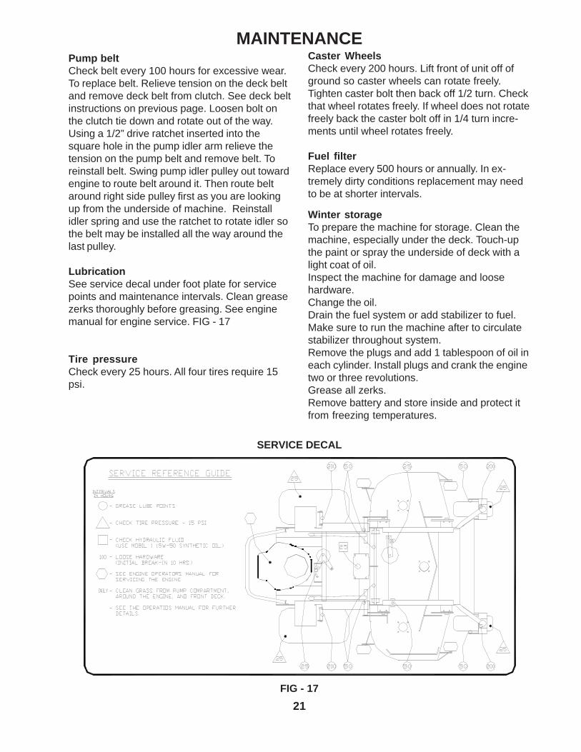
LubricationSee service decal under foot plate for servicepoints and maintenance intervals. Clean greasezerks thoroughly before greasing. See enginemanual for engine service. FIG - 17
Tire pressureCheck every 25 hours. All four tires require 15psi.
SERVICE DECAL
FIG - 17
Winter storageTo prepare the machine for storage. Clean themachine, especially under the deck. Touch-upthe paint or spray the underside of deck with alight coat of oil.Inspect the machine for damage and loosehardware.Change the oil.Drain the fuel system or add stabilizer to fuel.Make sure to run the machine after to circulatestabilizer throughout system.Remove the plugs and add 1 tablespoon of oil ineach cylinder. Install plugs and crank the enginetwo or three revolutions.Grease all zerks.Remove battery and store inside and protect itfrom freezing temperatures.
Caster WheelsCheck every 200 hours. Lift front of unit off ofground so caster wheels can rotate freely.Tighten caster bolt then back off 1/2 turn. Checkthat wheel rotates freely. If wheel does not rotatefreely back the caster bolt off in 1/4 turn incre-ments until wheel rotates freely.
Fuel filterReplace every 500 hours or annually. In ex-tremely dirty conditions replacement may needto be at shorter intervals.

22
Torque Specifications
· Engine crankshaft bolt 67 Nm(50 ft/lb)
· Deck pulley bolts 61 Nm (45 ft/lb)
· Hydraulic tube nuts 41 Nm (30 ft/lb)
· Wheel motor hub nut 122 Nm (90 ft/lb)
· Lug nuts 100 Nm (75 ft/lb)
· Blade bolt 122 Nm (90 ft/lb)
· Standard ¼” fasteners 12 Nm (9 ft/lb)
· Standard 5/16” fasteners 25 Nm (18 ft/lb)
· Standard 3/8” fasteners 44 Nm (33 ft/lb)
· Standard 7/16” fasteners 70 Nm (52 ft/lb)
· Standard ½” fasteners 110 Nm (80 ft/lb)
MAINTENANCE

23
Maintenance ScheduleFor ZTH Riders
Maintenance Maintenance Interval (hours)Daily 25 50 100 200 250 500
Engine (4)Check oil level XChange oil and filter (1) XClean the air filter’s (3) XReplace air filter’s (3) XCheck for fuel and oil leakage XClean cooling flanges (3) XCheck cooling air inlet XCheck fuel pump’s air filter XReplace fuel filter XReplace plugs X
HydraulicsCheck oil level XCheck for oil leaks XChange hydraulic oil (2) X XChange oil filter (2) X X
ElectricalCheck battery XCheck the safety system X
LubricateLeft and right brakes XLeft and right motion control shafts XLeft and right deck struts XDeck idler arm XPump idler arm XCaster swivels XCaster tires XDeck lift lever XThrottle cable XChoke cable XLubricate cutter housings X
GeneralCheck bolts and nuts XCheck cutting deck XClean cutting deck (3) XClean pump compartment (3) XCheck tire pressure (15 psi) XCheck belts XCheck and adjust throttle cable X
Notes:1. Change engine oil and filter after first 50 hours and then every 100 hours.2. Change hydraulic oil and filter after the first 250 hours or season and then every 500 hours.3. During dusty or dry conditions cleaning and replacement should be more frequent.4. Refer to engine manual for more information.
MAINTENANCE

24
TROUBLE SHOOTING
PROBLEM POSSIBLE CAUSES
ENGINE WILL NOT START.
Blade switch on.Drive levers not in the neutral slots.Operator not in seat.Park brake disengaged.Dead battery.Fuel valve closed or in the wrong position.No fuel.Spark plugs defective.Spark plug wires off.
MACHINE WILL NOT MOVE OR MOVESSLOWLY OR HARD.
Park brake on.Pump bypass valves open.Pump drive belt loose or off.Hydraulic system failure.Air in the hydraulic system.
BLADES WILL NOT ENGAGE.Blade belt off.Clutch unhooked form wiring harness.Blade switch failure or unhooked from harness.Fuse burnt out.
UNEVEN CUT
Tire pressure uneven.Blades bent.Deck chains uneven.Deck lift blocks loose.Anti-scalp rollers set uneven.
CUT IS RAGGEDBlades dull.Ground speed to fast.Grass to long.Grass accumulation under deck.
MACHINE VIBRATIONBlades loose.Blades unbalanced.Engine loose from mounts.

25
WIRING DIAGRAMS
CONSOLE HARNESS
Frame
Harness
Engine
Clutch
LeftM
otionC
ontrol
Hour
Meter
BladeSw
itch
Seat
StarterSw
itch
Right
Motion
Control
P/N104414

26
WIRING DIAGRAMS
CONSOLE HARNESS

27
FRAME HARNESS
WIRING DIAGRAMS
Clutch
EnginePigtail
Ground to
EngineStarterSolenoid
ParkBrake
Console
Harness
BrakeR
elay
StartR
elay
Run
Relay
P/N104964

28
WIRING DIAGRAMS
FRAME HARNESS

29