Operator’s Manual Light Tower, Wide Body LTW 20Z-1 …€¦ · Operator’s Manual Light Tower,...
94
5000187543 05 1111 5 0 0 0 1 8 7 5 4 3 Operator’s Manual Light Tower, Wide Body LTW 20Z-1 LTW 20Z-3 EN
Transcript of Operator’s Manual Light Tower, Wide Body LTW 20Z-1 …€¦ · Operator’s Manual Light Tower,...

5000187543 05 1111
5 0 0 0 1 8 7 5 4 3
Operator’s Manual
Light Tower, Wide Body
LTW 20Z-1LTW 20Z-3
EN

Copyright notice
© Copyright 2011 by Wacker Neuson Production Americas LLCAll rights, including copying and distribution rights, are reserved.This publication may be photocopied by the original purchaser of the machine. Any other type of reproduction is prohibited without express written permission from Wacker Neuson Production Americas LLC.Any type of reproduction or distribution not authorized by Wacker Neuson Production Americas LLC represents an infringement of valid copyrights. Violators will be prosecuted.
Trademarks All trademarks referenced in this manual are the property of their respective owners.
Manufacturer Wacker Neuson Production Americas LLCN92W15000 Anthony AvenueMenomonee Falls, WI 53051 U.S.A.Tel: (262) 255-0500 · Fax: (262) 255-0550 · Tel: (800) 770-0957www.wackerneuson.com
Original instructions
This Operator’s Manual presents the original instructions. The original language of this Operator’s Manual is American English.

Foreword
ForewordSAVE THESE INSTRUCTIONS—This manual contains important instructions for the machine models below. These instructions have been written expressly by Wacker Neuson Production Americas LLC and must be followed during installation, operation, and maintenance of the machines.Machines covered in this Manual
Machine documentation
From this point forward in this documentation, Wacker Neuson Production Americas LLC will be referred to as Wacker Neuson.Keep a copy of the Operator’s Manual with the machine at all times. Use the separate Parts Book supplied with the machine to order replacement parts. Refer to the separate Repair Manual for detailed instructions on servicing and repairing the machine.If you are missing any of these documents, please contact Wacker Neuson to order a replacement or visit www.wackerneuson.com. When ordering parts or requesting service information, be prepared to provide the machine model number, item number, revision number, and serial number.
Expectations for information in this manual
This manual provides information and procedures to safely operate and maintain the above Wacker Neuson model(s). For your own safety and to reduce the risk of injury, carefully read, understand, and observe all instructions described in this manual. Wacker Neuson expressly reserves the right to make technical modifications, even without notice, which improve the performance or safety standards of its machines.The information contained in this manual is based on machines manufactured up until the time of publication. Wacker Neuson reserves the right to change any portion of this information without notice.
CALIFORNIA Proposition 65 Warning
Engine exhaust, some of its constituents, and certain vehicle components, contain or emit chemicals known to the State of California to cause cancer and birth defects or other reproductive harm.
Laws pertaining to spark arresters
NOTICE: State Health Safety Codes and Public Resources Codes specify that in certain locations spark arresters be used on internal combustion engines that use hydrocarbon fuels. A spark arrester is a device designed to prevent accidental dis-charge of sparks or flames from the engine exhaust. Spark arresters are qualified and rated by the United States Forest Service for this purpose. In order to comply with local laws regarding spark arresters, consult the engine distributor or the local Health and Safety Administrator.
Machine Item NumberLTW 20Z-1 0620375, 0620842LTW 20Z-3 0620376, 0620843
wc_tx001055gb.fm 3

Foreword
Manufacturer’s approval
This manual contains references to approved parts, attachments, and modifica-tions. The following definitions apply:
Approved parts or attachments are those either manufactured or provided by Wacker Neuson. Approved modifications are those performed by an authorized Wacker Neuson service center according to written instructions published by Wacker Neuson.Unapproved parts, attachments, and modifications are those that do not meet the approved criteria.
Unapproved parts, attachments, or modifications may have the following conse-quences:
Serious injury hazards to the operator and persons in the work areaPermanent damage to the machine which will not be covered under warranty
Contact your Wacker Neuson dealer immediately if you have questions about approved or unapproved parts, attachments, or modifications.
4 wc_tx001055gb.fm

LTW 20Z Table of Contents
Foreword 31 Safety Information 9
1.1 Signal Words Used in this Manual ....................................................... 91.2 This manual contains DANGER, WARNING, CAUTION, NOTICE, and NOTE signal words which must be followed to reduce the possibility of personal injury, dam-age to the equipment, or improper service. ....................................................... 91.3 Machine Description and Intended Use ............................................... 91.4 Safety Guidelines for Operating the Machine ..................................... 111.5 Lamp Safety ....................................................................................... 121.6 Operator Safety while Using Internal Combustion Engines ............... 131.7 Towing Safety ..................................................................................... 141.8 Service Safety .................................................................................... 15
2 Labels 17
2.1 Label Locations .................................................................................. 172.2 Label Meanings .................................................................................. 19
3 Operation 32
3.1 Preparing the Machine for First Use ................................................... 323.2 Preparing Trailer for Towing or Lifting ................................................ 333.3 Locating the Trailer ............................................................................. 343.4 Ground Connection ............................................................................ 343.5 Leveling Trailer ................................................................................... 353.6 Refueling the Machine ........................................................................ 363.7 Adjusting the Lights ............................................................................ 373.8 Control Panel (Manual Winch System) .............................................. 383.9 Raising the Tower (Manual Winch System) ....................................... 393.10 Lowering the Tower (Manual Winch System) .................................... 423.11 Control Panel (Power Winch System) ................................................ 443.12 Raising the Tower (Power Winch System) ......................................... 453.13 Lowering the Tower (Power Winch System) ..................................... 483.14 Manually Starting the Machine ........................................................... 503.15 Stopping the Machine ......................................................................... 513.16 Auto Mode (Remote Run) .................................................................. 513.17 Troubleshooting Automatic Shutdown ................................................ 523.18 Generator Derating ............................................................................. 533.19 Receptacle Panel ............................................................................... 543.20 Load Balancing ................................................................................... 56
wc_bo5000187543_05TOC.fm 5

Table of Contents LTW 20Z
3.21 Electronic Governor .............................................................................563.22 Emergency Stop Switch ......................................................................574 Maintenance 58
4.1 Periodic Maintenance Schedule ..........................................................584.2 Installing / Removing Light Fixtures ....................................................604.3 Removing / Replacing Lamps .............................................................614.4 Performing Daily Inspection ................................................................624.5 Checking Engine Coolant ....................................................................634.6 Replacing Air Cleaner .........................................................................644.7 Changing Engine Oil ...........................................................................654.8 Maintaining the Fuel/Water Separator .................................................674.9 Maintaining the Trailer .........................................................................674.10 Long-Term Storage .............................................................................684.11 Troubleshooting ...................................................................................69
5 Factory-Installed Options 70
5.1 General Options ..................................................................................705.2 Cold Weather Options .........................................................................755.3 North Slope Options ............................................................................75
6 Technical Data 78
6.1 Engine .................................................................................................786.2 Generator ............................................................................................796.3 Machine ...............................................................................................806.4 Dimensions ..........................................................................................816.5 Radiation Compliance .........................................................................81
7 Schematics 83
7.1 LTW 20Z-1—Electrical Schematic ......................................................847.2 LTW 20Z-1—Electrical Schematic Components .................................857.3 LTW 20Z-3—Electrical Schematic ......................................................867.4 LTW 20Z-3—Electrical Schematic Components .................................877.5 Engine Wiring ......................................................................................887.6 Engine Wiring Components .................................................................897.7 Trailer Wiring (Electric Brakes) ............................................................907.8 Trailer Wiring Components (Electric Brakes) ......................................90
6 wc_bo5000187543_05TOC.fm

LTW 20Z Table of Contents
7.9 Trailer Wiring (Surge Brakes / No Brakes) ......................................... 91wc_bo5000187543_05TOC.fm 7

Table of Contents LTW 20Z
8 wc_bo5000187543_05TOC.fm

LTW 20Z Safety Information
1 Safety Information1.1 Signal Words Used in this Manual
1.2 This manual contains DANGER, WARNING, CAUTION, NOTICE, and NOTE signal words which must be followed to reduce the possibility of personal injury, damage to the equipment, or improper service.
NOTICE: Used without the safety alert symbol, NOTICE indicates a situation which, if not avoided, could result in property damage.
Note: A Note contains additional information important to a procedure.
1.3 Machine Description and Intended UseThis machine is a mobile, trailer-mounted light tower. The Wacker Neuson Light Tower consists of a trailer with a cabinet containing a diesel engine, a fuel tank, a control panel, and an electric alternator. A telescoping tower with four metal halide lights is mounted to the top of the cabinet. Dual winches tilt, raise, and lower the telescoping tower. As the engine runs, the generator converts mechanical energy into electric power. The metal halide lights run off this power. Receptacle(s) are also present to power auxiliary loads. The operator uses the control panel to operate and monitor the machine.
This is the safety alert symbol. It is used to alert you to potential personal hazards.Obey all safety messages that follow this symbol.
DANGERDANGER indicates a hazardous situation which, if not avoided, will result in death or serious injury.
To avoid death or serious injury from this type of hazard, obey all safety messages that follow this signal word.
WARNINGWARNING indicates a hazardous situation which, if not avoided, could result in death or serious injury.
To avoid possible death or serious injury from this type of hazard, obey all safety mes-sages that follow this signal word.
CAUTION! CAUTION indicates a hazardous situation which, if not avoided, could result in minor or moderate injury.
To avoid possible minor or moderate injury from this type of hazard, obey all safety mes-sages that follow this signal word.
wc_si000301gb.fm 9

Safety Information LTW 20Z
This machine is intended for the illumination of outdoor areas. This machine is also intended for the purpose of supplying electrical power to connected loads. Refer to the product specifications for the output voltage and frequency of this Light Tower, and for the maximum output power limit of this Light Tower.
This machine has been designed and built strictly for the intended use described above. Using the machine for any other purpose could permanently damage the machine or seriously injure the operator or other persons in the area. Machine damage caused by misuse is not covered under warranty.
The following are some examples of misuse:Connecting a load that has voltage and frequency requirements that are incompatible with the machine outputOverloading the machine with a device that draws excessive power during either continuous running or start-upOperating the machine in a manner that is inconsistent with all federal, state and local codes and regulationsUsing the machine as a ladder, support, or work surfaceUsing the machine to carry or transport passengers or equipmentUsing the machine to tow other machines (unless factory equipped)Using the machine as a hoist or hanging items from the towerOperating the machine outside of factory specificationsOperating the machine in a manner inconsistent with all warnings found on the machine and in the Operator’s Manual
This machine has been designed and built in accordance with the latest global safety standards. It has been carefully engineered to eliminate hazards as far as practicable and to increase operator safety through protective guards and labeling. However, some risks may remain even after protective measures have been taken. They are called residual risks. On this machine, they may include exposure to:
Heat, noise, exhaust, and carbon monoxide from the engineHeat from the lightsUltraviolet radiation from the lightsFire hazards from improper refueling techniquesFuel and its fumesElectric shock and arc flashPersonal injury from improper lifting the trailer tongueGlare from lights (lights may blind drivers of nearby motor vehicles if the lights are incorrectly positioned)Typical hazards related to towing a trailer on roads and highways
To protect yourself and others, make sure you thoroughly read and understand the safety information presented in this manual before operating the machine.
10 wc_si000301gb.fm

LTW 20Z Safety Information
1.4 Safety Guidelines for Operating the MachineOperator training Before operating the machine:Read and understand the operating instructions contained in all manuals delivered with the machine.Familiarize yourself with the location and proper use of all controls and safety devices. Contact Wacker Neuson for additional training if necessary.
When operating this machine:Do not allow improperly trained people to operate the machine. People operating the machine must be familiar with the potential risks and hazards associated with it.
Personal Protective Equipment (PPE)
Wear the following Personal Protective Equipment (PPE) while operating this machine:
Close-fitting work clothes that do not hinder movementSafety glasses with side shieldsHearing protectionSafety-toed footwear
Work area Make sure the area immediately surrounding the Light Tower is clean, neat, and free of debris.The tower extends up to 9 m (30 ft). Make sure the area above the trailer is open and clear of overhead wires and obstructions.
Machine setup Make sure the machine is on a firm, level surface and will not tip, roll, slide, or fall while operating.Make sure the machine is well-grounded and securely fastened to a good earthen ground per national and local regulations.The trailer must be leveled and the outriggers extended before raising the tower. The outriggers must be extended while the tower is up.Never connect the machine to other power sources, such as supply mains of power companies.
Machine integrity
Do not start a machine in need of repair.Do not use the machine if the insulation on any electrical cord is cut or worn through.Do not operate the lights without the protective lens cover in place or with a lens cover that is cracked or damaged.Replace or repair electrical components with components that are identical in rating and performance to the originals.
While operating the machine
Keep the area behind the trailer clear of people and obstructions while rais-ing and lowering the tower.Do not raise the tower or operate the machine in high winds. Lower the tower immediately if high winds or electrical storms are expected in the area.
wc_si000301gb.fm 11

Safety Information LTW 20Z
Do not raise, lower, or turn the tower while the unit is operating.If any part of the tower hangs up, or the winch cable develops slack while raising or lowering the tower, STOP immediately! Contact an authorized Wacker Neuson service representative.Do not disengage the tower locking pin while the tower is up.Lamps become extremely hot in use! Allow the lamps and fixtures to cool 10–15 minutes before handling.Lower the tower when not in use.1.5 Lamp SafetyDescription The lamps provided with your Light Tower are electric discharge lamps. They
are designed for use with metal halide ballasts only, and require time to reach full brightness on initial startup and after a power interruption. These lamps comply with FDA regulation performance standards 21 CFR 1040-30.
Operating safety Do not operate the lamps where people will remain for more than a few minutes unless adequate shielding or other safety precautions are used. Replace damaged lamps according to the instructions in section Removing / Replacing Lamps.Lamps that automatically extinguish when the outer envelope is broken or punctured are commercially available.
WARNINGPersonal injury hazard. Lamps can cause serious skin burns and eye inflammation from shortwave ultraviolet radiation if outer envelope of the lamp is broken or punc-tured.
Do not operate the Light Tower if a lamp is damaged.
12 wc_si000301gb.fm

LTW 20Z Safety Information
1.6 Operator Safety while Using Internal Combustion EnginesOperating safety When running the engine:Keep the area around exhaust pipe free of flammable materials.Check the fuel lines and the fuel tank for leaks and cracks before starting the engine. Do not run the machine if fuel leaks are present or the fuel lines are loose.
When running the engine:Do not smoke while operating the machine.Do not run the engine near sparks or open flames.Do not touch the engine or muffler while the engine is running or immedi-ately after it has been turned off.Do not operate a machine when its fuel cap is loose or missing. Do not start the engine if fuel has spilled or a fuel odor is present. Move the machine away from the spill and wipe the machine dry before starting.
Refueling safety When refueling the engine:Clean up any spilled fuel immediately.Refill the fuel tank in a well-ventilated area.Replace the fuel tank cap after refueling.Do not smoke.Do not refuel a hot or running engine.Do not refuel the engine near sparks or open flames.
WARNINGInternal combustion engines present special hazards during operation and fueling. Failure to follow the warnings and safety standards could result in severe injury or death.
Read and follow the warning instructions in the engine owner’s manual and the safety guidelines below.
DANGERExhaust gas from the engine contains carbon monoxide, a deadly poison. Expo-sure to carbon monoxide can kill you in minutes.
NEVER operate the machine inside an enclosed area, such as a tunnel, unless adequate ventilation is provided through such items as exhaust fans or hoses.
wc_si000301gb.fm 13
Safety Information LTW 20Z
1.7 Towing SafetyRead and follow the information below:Equipment integrity
Both the trailer and vehicle must be in serviceable condition and securely fastened together.Ensure that the hitch and coupling on the towing vehicle are rated equal to, or greater than, the trailer’s Gross Vehicle Weight Rating (GVWR).Inspect the hitch and coupling for wear or damage. Do not tow the trailer using defective parts.Always connect the safety chains.Make sure all directional and trailer lights are connected and working prop-erly.Check the tires on the trailer for tread wear, inflation, and condition. Replace worn tires.Verify that all lug nuts holding the wheels are tight and none are missing.
Checking brakes On trailers with surge or electric brakes, connect the breakaway cable (a) on the trailer coupler to the rear bumper or frame of the vehicle. This cable will actuate the brake system on the trailer if both the coupling and safety chains have failed. The breakaway cable is not a parking brake and should not be used as one.
Check the operation of the brakes by braking the vehicle at a slow speed before entering traffic. Both the vehicle and the trailer should brake smoothly. If the trailer seems to be pushing, check the fluid level (b) in the surge brakes or the operation of the electric brakes.
Towing speed The maximum recommended speed for highway towing is 88 km/hour (55 mph). Recommended off-road towing speed is not to exceed 16 km/hour (10 mph) or less depending on terrain.
WARNINGPossibility of personal injury or equipment damage. Towing a large trailer can be hazardous without careful preparation, appropriate equipment, and/or observance of maximum towing speeds.
Refer to the applicable Department of Transportation regulations before towing.
wc_gr006973
a
b
14 wc_si000301gb.fm

LTW 20Z Safety Information
1.8 Service SafetyPrecautions To reduce the risk of personal injury, read and understand the service pro-cedures before performing any service to the machine.All adjustments and repairs MUST be completed before operation. Do not operate the machine with a known problem or deficiency! All repairs and adjustments should be completed by a qualified technician.Do not service the machine if your clothing or skin is wet.
Personal Protective Equipment (PPE)
Wear the following Personal Protective Equipment (PPE) while servicing or maintaining this machine:
Close-fitting work clothes that do not hinder movementSafety glasses with side shieldsHearing protectionSafety-toed footwear
In addition, before servicing or maintaining the machine:Tie back long hair.Remove all jewelry (including rings).
Before servicing the machine
Turn the engine off before performing maintenance or making repairs.Make sure the engine start switch is turned to OFF.Make sure the circuit breakers are open (off).Make sure the negative terminal on the battery is disconnected.Do not perform even routine service (oil / oil filter changes, cleaning, etc.) unless all electrical components are shut down.Make sure water has not accumulated around the base of the machine. If water is present, move the machine and allow it to dry before servicing.If the machine must be started while servicing, keep hands, feet, and loose clothing away from moving parts on the generator and engine.
Safety devices and modifications
Replace all safety devices and guards after repair and maintenance.Do not modify the machine without the express written approval of the man-ufacturer.
Replacing parts and labels
Replace worn or damaged components.Use only spare parts recommended by Wacker Neuson.Replace all missing and hard-to-read labels. Check all external fasteners at regular intervals.
WARNINGHigh voltage! This machine produces high voltage capable of causing serious injury or death.
Only a qualified electrician should troubleshoot or repair electrical problems occurring with this machine.
wc_si000301gb.fm 15

Safety Information LTW 20Z
Lifting and transportingWhen lifting the machine:Make sure slings, chains, hooks, ramps, jacks and other types of lifting devices are attached securely and have enough weight-bearing capacity to lift or hold the machine safely. Remain aware of the location of other people when lifting the machine.
To reduce the possibility of injury:Do not stand under the machine while it is being hoisted or moved.Do not get onto the machine while it is being hoisted or moved.
16 wc_si000301gb.fm
LTW 20Z Labels
2 Labels2.1 Label Locations
wc_gr006242
1 2
BBBB OO
DDRRDD
KK
BBBB
BB
DDFCC
L
V
LL
NN
SS
LLW
FF D FF
DD
B
Y
Y
wc_si000386gb.fm 17

Labels LTW 20Z
wc_gr006243BB Q R
O
B
DD
GG
J
CN
FFD
I G FF E
U
V
S
A
HHH
T
J
MM
PP
SS
JJ
TAA
NN
KK
TT
M
18 wc_si000386gb.fm

LTW 20Z Labels
2.2 Label MeaningsA WARNINGAutomatic locking pin.A non-secured, falling tower can cause serious injury or death if a person is hit. To secure tower, verify automatic locking pin has been engaged.
B WARNING! Avoid crushing area.
C DANGER!Contact with overhead electrical power lines will cause serious injury or death. Do not position Light Tower under electrical power lines.WARNING! Completely lower tower BEFORE tilting tower. Tilting an extended tower can cause serious injury or death.
D NOTICELifting point.
wc_si000386gb.fm 19

Labels LTW 20Z
E WARNING! Secure tower in transport lock before lifting or towing. A loose swinging tower could cause per-sonal injury or machine damage.
F DANGER
Using a light tower indoors CAN KILL YOU IN MINUTES. Light tower exhaust contains carbon monoxide. This is a poison you cannot see or smell.
NEVER use inside a home or garage, EVEN IF doors and windows are open.
Only use OUTSIDE and far away from windows, doors, and vents.
G DANGER!
Asphyxiation hazard. Engines emit carbon monoxide. Do not run the machine indoors or in an enclosed area unless adequate ventilation, through such items as exhaust fans or hoses, is provided. Read the Operator’s Manual. No sparks, flames, or burning objects near the machine. Stop the engine before refueling.
20 wc_si000386gb.fm

LTW 20Z Labels
H WARNING! Electric shock and arc flash can cause serious injury or death. Electrical storage device within. Contact a qualified electrician for service or to open electrical box.
I WARNING!Read and understand the supplied Operator’s Manual before operating the machine. Failure to do so increases the risk of injury to yourself and others.
wc_si000386gb.fm 21

Labels LTW 20Z
J WARNING! Stand clear of front and rear of machine when tower is being tilted up or down.
K WARNING! Hot surface
L WARNING! Hot surface
M A nameplate listing the model number, item num-ber, revision number, and serial number is attached to each unit. Please record the informa-tion found on this nameplate so it will be available should the nameplate become lost or damaged. When ordering parts or requesting service infor-mation, you will always be asked to specify the model number, item number, revision number, and serial number of the unit.
22 wc_si000386gb.fm

LTW 20Z Labels
N WARNING! Ultraviolet radiation from lamp can cause serious skin and eye irritation. Use only with undamaged lamps. Use only with provided undamaged lens cover and fixture.
O See Operator’s Manual for metal halide lamp information and troubleshooting.
Before starting engine
Check levels Engine oilFuelCoolant
Circuit breakers off
Start engine
Engine control panel
Press pushbutton
Will light during preheat
Engine will start automatically after preheat cycle
Circuit breakers on
Shut downCircuit breakers offStop engine
wc_si000386gb.fm 23

Labels LTW 20Z
Q Manual Winch System
To raise tower: 1. Release transport lock.2. Tilt tower using winch.3. Tilt tower until automatic locking pin snaps into place.
To increase height of tower:4. Raise tower using winch.
To aim lights:5. Rotate tower and tighten knob.
24 wc_si000386gb.fm

LTW 20Z Labels
R Manual Winch System
To lower tower:1. Turn off all lights and engine.2. Rotate tower and tighten knob.3. Lower tower using winch.
To tilt tower for transport:4. Release and hold spring-loaded pin.5. Tilt tower using winch.
To secure tower for transport:6. Insert pin through transport lock and secure with pin.7. Position light fixtures down.
wc_si000386gb.fm 25

Labels LTW 20Z
Q Power Winch System
To raise tower: 1. Release transport lock.2. Tilt tower using winch.3. Tilt tower until automatic locking pin snaps into place.
To increase height of tower:4. Raise tower using winch.
To aim lights:5. Rotate tower and tighten knob.
R Power Winch System
To lower tower:1. Turn off all lights and engine.2. Rotate tower and tighten knob.3. Lower tower using winch.
To tilt tower for transport:4. Release and hold spring-loaded pin.5. Tilt tower using winch.
To secure tower for transport:6. Insert pin through transport lock and secure with pin.7. Position light fixtures down.
26 wc_si000386gb.fm

LTW 20Z Labels
S WARNING! Disconnect battery before servicing.Read the Operator’s Manual.
T WARNING! Pressurized contents. Do not open when hot!
U Coolant overflow bottle only, not a return system.
V WARNING!Pinching hazard. Rotating machinery.
W WARNING! Electric shock and arc flash can cause serious injury or death.
wc_si000386gb.fm 27

Labels LTW 20Z
Y Electrical ground
AA Operator’s Manual must be stored on machine. Replacement Operator’s Manual can be ordered through your local Wacker Neuson distributor.
BB Tie-down point
CC Ultra low sulfur fuel only.
DD Insert jack locking pin before extending jack.
FF Fork lift pocket
GG Read Operator’s Manual.Use hitch rated from trailer’s “Gross Vehicle Weight Rating”.Securely attach trailer to tow vehicle.Attach safety chains using cross pattern.Attach breakdown chain to vehicle.Check trailer lights.
28 wc_si000386gb.fm

LTW 20Z Labels
HH Neutral bonded to frame
JJ Fuses
1.Not used2. Controller3. Fuel pump / solenoid4. Alternator
KK Certification Label (VIN Number)Also attached to each unit is a Certification Label. This label specifies that the trailer conforms with all Federal Motor Vehicle Standards in effect at the time of manufacture. The label includes the Vehicle Identification Number (VIN) for the trailer.
LL WARNING! Electric shock and arc flash can cause serious injury or death. Electrical storage device within. Contact a qualified electrician for service or to open electrical box.
MM Transport position of the jack
NN Not a step
wc_si000386gb.fm 29

Labels LTW 20Z
OO WARNING
When towing in tandem:Do not tow on highwayDo not tow more than two unitsDo not exceed 35 mph (55 kph)
Maximum Gross Vehicle Weight Rating (GVWR)
Maximum Tongue Weight
PP Engine controlsHour meter
QQ Protecting Our Environment
Fluid containment system
(if equipped)
RR Skid drain access point
SS CAUTIONWheel nuts must be tightened to 85 ft.lbs.
TT WARNING
Operation of this equipment may create sparks that can start fires around dry vegetation. A spark arrester may be required. The operator should contact local fire agencies for laws or regulations relating to fire prevention requirements.
30 wc_si000386gb.fm
LTW 20Z Labels
This machine may be covered by one or more patents.
UTILITY 159116UTILITY 159116
U.S.PAT.Nos.: 6012285, 6471476, U.S.PAT.Nos.: 6012285, 6471476, D416858, D454357 OTHER U.S. AND D416858, D454357 OTHER U.S. AND FOREIGN PATENTS PENDINGFOREIGN PATENTS PENDING
wc_si000386gb.fm 31

Operation LTW 20Z
3 Operation3.1 Preparing the Machine for First Use
Preparing for first use
To prepare your machine for first use:
1. Make sure all loose packaging materials have been removed from the machine.2. Check the machine and its components for damage. If there is visible damage,
do not operate the machine! Contact your Wacker Neuson dealer immediately for assistance.
3. Take inventory of all items included with the machine and verify that all loose components and fasteners are accounted for.
4. Attach component parts not already attached.5. Add fluids as needed and applicable, including fuel, engine oil, and battery acid.6. Move the machine to its operating location.
CO Alarms Because this machine produces carbon monoxide (CO), Wacker Neuson recommends that CO alarms be installed in all structures in close proximity to the machine. CO alarms provide an extra measure of protection against this poison that you cannot see or smell.Install battery-operated CO alarms or plug-in CO alarms with battery backup, according to the manufacturer’s instructions. CO alarms should be certified to the requirements of the latest safety standards (UL 2034, IAS 6-96, or CSA 6.19.01). Test the CO alarm batteries monthly.
32 wc_tx001058gb.fm

LTW 20Z Operation
3.2 Preparing Trailer for Towing or LiftingNOTICE: Allow the lights to cool 10–15 minutes before lifting or moving the trailer. Moving the trailer while the lights are still hot could cause the lamps to break.
Preparing the trailer for lifting
Follow the procedure below to prepare the trailer for lifting.
1. Ensure that the tower is completely nested inside the transport cradle and the pin (t) is secure.
2. Check that the tower cradle lock pin (j) is in place and secured with the safety pin
3. Make sure the doors are properly latched.4. Return the outriggers to their travel position. Check that the outrigger bars and
jacks are locked in place.5. Crank the rear jack (f) all the way in and rotate it 90°. The Light Tower is now ready to lift. Use the designated lift points.
Preparing the trailer for towing
Follow the procedure below to prepare the trailer for towing.
1. Prepare the trailer for lifting as described above.2. Use the tongue jack (a) to raise the trailer tongue up and then lower it over hitch
on towing vehicle. 3. Lock the hitch to coupling and attach the safety chains. 4. Swivel the tongue jack 90° and lock it in place.5. Connect the trailer wiring to the towing vehicle. Check the brake, turn, and tail
lights for proper operation.6. Position the light fixtures down (k). For rough, off-road transportation remove
lamps from fixtures to avoid damage. 7. Check the tire inflation.
Towing speed The maximum recommended speed for highway towing is 88 km/hour (55 mph). Recommended off-road towing speed is not to exceed 16 km/hour (10 mph) or less depending on terrain.
wc_gr006223
a
j t
t
j k
f
wc_tx001058gb.fm 33

Operation LTW 20Z
3.3 Locating the TrailerPositioning the machineFor maximum light coverage, locate the Light Tower at ground level or in a spot higher than the area being lighted.
Make sure that there is enough area for outrigger extensions to be fully extended.
3.4 Ground ConnectionA ground connection (l) is located on the trailer frame.
Function This ground connection is used for electrically grounding the Light Tower when necessary to comply with the National Electrical Code and other federal, state, and local regulations. For grounding requirements in your area, consult with a qualified electrician, electrical inspector, or local agency having jurisdiction over electrical compliance.
If the Light Tower is used at a construction site, there may be additional regulations which must be observed.
WARNINGElectric shock or equipment damage hazards. The tower extends up to 9 m (30 ft.) and could interfere with overhead wires and obstructions.
Position the trailer on a firm, flat surface clear of overhead wires and obstructions.
l
LTN LTwc_gr005225
l
l
LTN LTW
34 wc_tx001058gb.fm

LTW 20Z Operation
3.5 Leveling TrailerP
Procedure Follow the procedure below to level the trailer.
1. Pull the locking pin on the tongue jack (a) and rotate the tongue jack down 90° as shown. Reinsert the pin once the jack is in position.
2. Block or chock the trailer wheels (b). Crank the tongue jack down to raise the trailer tongue off the vehicle.
3. Pull the outrigger lock pin (c) to release the outrigger. Pull both outrigger extensions (d) out until you feel outrigger lock pin lock back into place.
4. Pull the locking pins on the outrigger jacks (e). Rotate the jacks 90° down. Reinsert the pins once the jacks are in position.
5. Pull the locking pin on the rear jack (f) and rotate the rear jack down 90° as shown. Reinsert the pin once the jack is in position.
6. Extend the jack(s) on the highest side(s) of the trailer until they rest firmly on the ground. Extend the remaining jacks until the trailer is level.
WARNINGTipping / falling hazard. Failure to level the trailer or extend the outriggers will severly reduce the stability of the unit.
Level the trailer and extend the outriggers before raising the tower. The outriggers must remain extended while the tower is up.
wc_gr005874
wc_tx001058gb.fm 35

Operation LTW 20Z
3.6 Refueling the MachineRequirements Machine shut downEngine coolMachine/fuel tank level with the groundFresh, clean fuel supply
Procedure Perform the procedure below to refuel the machine.
1. Remove the fuel cap (a).
2. Fill the fuel tank to the bottom of the fuel tank neck (b).
3. Reinstall the fuel cap.
Result The procedure to refuel the machine is now complete.
WARNINGFire hazard. Fuel and its vapors are extremely flammable. Burning fuel can cause severe burns.
Keep all sources of ignition away from the machine while refueling.Refuel only when the machine is outdoors.Clean up spilled fuel immediately.
wc_gr008817
a
a
b
CAUTIONFire and health hazard. Fuel expands when heated. Expanding fuel in an over-filled tank can lead to spills and leaks.
Do not overfill the fuel tank.
36 wc_tx001058gb.fm

LTW 20Z Operation
3.7 Adjusting the LightsBackground Each light fixture can be aimed up, down, left, or right.Procedure Follow the procedure below to adjust the lights.
1. Loosen the toolless light adjusters (g).
2. Aim the light fixtures up or down. 3. Loosen the nuts (h).4. Turn the light fixtures left or right. 5. Tighten adjusters and nuts after positioning the lights.
NOTICE: Do not loosen the inside nut (x). Loosening this nut could damage the light fixture.
wc_gr005226
wc_tx001058gb.fm 37

Operation LTW 20Z
3.8 Control Panel (Manual Winch System)Ref. Description Ref. Descriptiona Main circuit breaker h Charge failure indicator
b 15 Amp lights circuit breaker j Overcrank shutdown fault indicator
c Hour meter k Glow plug indicator
d Low oil pressure shutdown indicator
l Safety shutdown indicator
e High coolant temperature shutdown
m Stop switch
f Overspeed shutdown fault indicator
n Start switch
g Underspeed shutdown fault indicator
o Auto
38 wc_tx001058gb.fm

LTW 20Z Operation
3.9 Raising the Tower (Manual Winch System)Background The Light Tower includes two separate winches—one for lifting the tower to the vertical position, the other for raising the tower. Each winch is an automatic brake-type winch that automatically brakes when the handle is released. The handle must be rotated to wind in the cable as well as to unwind the cable.
Prerequisites Machine is shut downLight Tower is located on a firm, flat surface clear of overhead wires and obstructionsWinch cables are in serviceable condition and resting properly in pulleysLight tower has been leveled, with all outriggers extended and locked
This procedure continues on the next page.
WARNINGElectric shock hazard! Do not use the Light Tower if insulation on any of the electrical cords is cut or worn through. Bare wires in contact with the metal frame of the trailer or tower can cause elecrocution.
Repair or replace the cord before using the machine.
WARNINGElectrocution hazard.
Do not position the Light Tower under electrical power lines.
WARNINGTipping/falling hazards. Certain actions may cause the tower to fall or the Light Tower to tip over.
Do not extend the tower beyond the red marking on the tower shaft.Do not raise the tower or operate the Light Tower in high winds.Do not touch the winch pawl while the tower is raised!Do not pull the vertical tower locking pin while the tower is raised.
WARNINGPersonal injury hazard. Bystanders can be struck by the tower as it is being raised or lowered.
Do not allow anyone to stand near the rear of the machine while raising or lowering the tower.
wc_tx001058gb.fm 39

Operation LTW 20Z
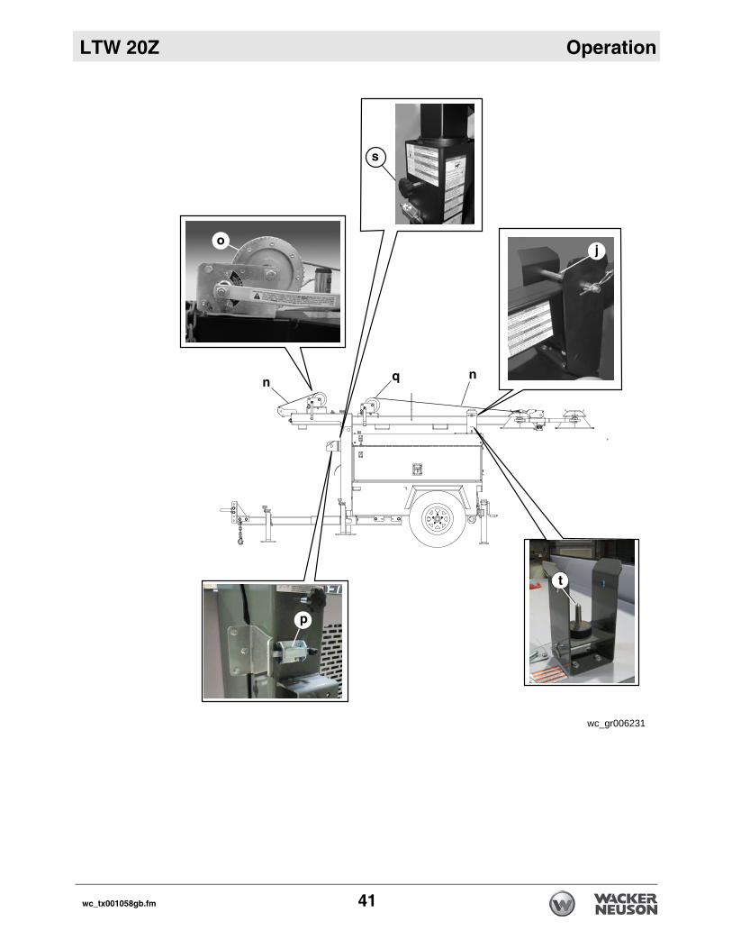
Procedure Follow the procedure below to raise the tower.Lifting the tower to the vertical position
1. Remove the cradle locking pin (j) from the cradle.2. Check the operation of the tilt winch (o) by rotaing the winch handle 1/4 turn
clockwise (“cable in” direction). The winch pawl must engage the winch gear teeth. When operating properly, the winch pawl will make a “clicking” sound when the winch handle is rotated clockwise.
NOTICE: Do not attempt to lift the tower if the winch is damaged or not operating properly, or if the winch cables are worn or damaged.
3. Continue to rotate the winch handle and lift the tower to the vertical position until the vertical tower locking pin (p) locks the tower in place. Be certain the vertical tower locking pin is fully engaged in the locking position before raising the tower.
Raising the tower
4. After the tower is vertical, check the operation of the telescoping winch (q) by rotating the winch handle 1/4 turn clockwise (“cable in” direction). The winch pawl must engage the winch gear teeth. When operating properly, the winch pawl will make a “clicking” sound when the winch handle is rotated clockwise.
NOTICE: Do not attempt to raise the tower if the winch is damaged or not operat-ing properly, or if the winch cables are worn or damaged.
5. Continue rotating the winch handle until the tower is at the desired height. Do not overcrank the winch when the tower is fully extended.
Rotating the tower
Once the tower is at the desired height, rotate the tower to the desired direction.
1. Loosen the rotation locking knob (s). 2. Rotate the tower until the lights face the desired direction.3. Retighten the rotation locking knob.
40 wc_tx001058gb.fm
LTW 20Z Operation
wc_gr006231
wc_tx001058gb.fm 41

Operation LTW 20Z
3.10 Lowering the Tower (Manual Winch System) Prerequisites Operating instructions have been read and understoodLights are turned offEngine is shut downWinch cables are in serviceable condition and resting properly in pulleys
Procedure Follow the procedure below to lower the tower.
1. Turn the handle on the telescoping winch (q) counterclockwise (“cable out” direction).
2. Loosen the rotation locking knob (s) and rotate the tower so the lights face the rear of the trailer and the telescoping winches are facing toward the trailer tongue.
3. Pull and hold the tower locking pin (p). Rotate the handle on the tilt winch (o) counterclockwise (“cable out” direction) until the tower spring begins to pivot the tower down.
NOTICE: If the tower hangs up, level the trailer, and sllightly shake or twist the tower assembly to free the bind. Contact an authorized Wacker Neuson service center immediately if this procedure does not correct the problem.
4. Release the tower locking pin and continue to rotate the handle until the tower is resting in the transport cradle. Make sure that the secondary locking pin (t) penetrates all sections of the tower.
5. After the tower is down, secure it in the cradle by inserting the cradle lock pin (j). Insert the clip through the pin to lock it in place.
6. Position the light fixtures to aim at the ground.
WARNINGTipping/falling hazards. Certain actions may cause the tower to fall or the machine to tip over.
Do not extend the tower beyond the red marking on the tower shaft.Do not raise the tower or operate the Light Tower in high winds.Do not touch the winch pawl while the tower is raised!Do not pull the vertical tower locking pin while the tower is raised.
WARNINGPersonal injury hazard. Bystanders can be struck by the tower as it is being raised or lowered.
Do not allow anyone to stand near the rear of the machine while raising or lowering the tower.
WARNINGPersonal injury hazard. Tower could collapse if the winch cable develops slack.
Stop turning the winch immediately if part of the tower hangs up, or if a winch cable develops slack before the tower is fully lowered.
42 wc_tx001058gb.fm

LTW 20Z Operation
wc_gr006231
wc_tx001058gb.fm 43

Operation LTW 20Z
3.11 Control Panel (Power Winch System)Ref. Description Ref. Descriptiona Main circuit breaker j Overcrank shutdown fault indicator
b 15 Amp lights circuit breaker k Glow plug indicator
c Hour meter l Safety shutdown indicator
d Low oil pressure shutdown indicator
m Stop switch
e High coolant temperature shutdown
n Start switch
f Overspeed shutdown fault indicator
o Auto
g Underspeed shutdown fault indicator
p Tilt rotary switch
h Charge failure indicator q Telescope rotary switch
q
p
44 wc_tx001058gb.fm

LTW 20Z Operation
3.12 Raising the Tower (Power Winch System)Background The Light Tower includes two separate winches—one for lifting the tower to the vertical position, the other for raising the tower.
Prerequisites Machine is shut downLight Tower is located on a firm, flat surface clear of overhead wires and obstructionsWinch cables are in serviceable condition and resting properly in pulleysLight Tower has been leveled, with all outriggers extended and locked
WARNINGElectric shock hazard! Do not use the Light Tower if insulation on any of the electrical cords is cut or worn through. Bare wires in contact with the metal frame of the trailer or tower can cause elecrocution.
Repair or replace the cord before using the machine.
WARNINGElectrocution hazard.
Do not position the Light Tower under electrical power lines.
WARNINGTipping/falling hazards. Certain actions may cause the tower to fall or the Light Tower to tip over.
Do not extend the tower beyond the red marking on the tower shaft.Do not raise the tower or operate the Light Tower in high winds.Do not touch the winch pawl while the tower is raised!Do not pull the vertical tower locking pin while the tower is raised.
WARNINGPersonal injury hazard. Bystanders can be struck by the tower as it is being raised.
Do not allow anyone to stand near the rear of the machine while raising the tower.
wc_tx001058gb.fm 45
Operation LTW 20Z
Procedure Follow the procedure below to raise the tower.Lifting the tower to the vertical position
1. Remove the cradle locking pin (j) from the cradle.
2. Check the operation of the tilt winch (r). Turn the tilt rotary switch (p) on the control panel to the up position. The tower should begin to tilt.
Note: It is normal for smoke to be produced during the first few operations of a new power winch.
NOTICE: Do not attempt to lift or raise the tower if the winch is damaged or not operating properly, or if the winch cables are worn or damaged. Continuous run-ning of the winch in excess of 4 minutes will damage the winch motor.
3. Hold the tilt rotary switch in the up position and raise the tower to the vertical position until the vertical tower locking pin (u) locks the tower in place. Be certain the vertical tower locking pin is fully engaged in the locking position before raising the tower.
Raising the tower
4. After the tower is vertical, check the operation of the telescoping winch (v). Turn the telescope rotary switch (q) on the control panel to the up position.
5. Continue to hold the telescope rotary switch until the tower is at the desired height. Release the switch when the tower is fully extended.
Rotating the tower
Once the tower is at the desired height, rotate the tower to the desired direction.
1. Loosen the rotation locking knob (s).
2. Rotate the tower until the lights face the desired direction.
3. Retighten the rotation locking knob.
46 wc_tx001058gb.fm

LTW 20Z Operation
wc_gr006972
r
v
u
wc_tx001058gb.fm 47

Operation LTW 20Z
3.13 Lowering the Tower (Power Winch System) Prerequisites Operating instructions have been read and understoodLights are turned offEngine is shut downWinch cables are in serviceable condition
Procedure Follow the procedure below to lower the tower.4. Lower the tower by turning and holding the telescope rotary switch (q) in the down
position.
NOTICE: Continuous running of the winch in excess of 4 minutes will damage the winch motor.
Note: It is normal for smoke to be produced during the first few operations of a new power winch.
5. Loosen the rotation locking knob (s) and rotate the tower so the lights face the rear of the trailer and the telescoping winch faces the trailer tongue.
6. Pull and hold the tower locking pin (u). Turn and hold the tilt rotary switch (p) on the control panel in the down position until the tower is resting in the transport cradle. Make sure that the secondary locking pin (t) penetrates all sections of the tower.
NOTICE: If the tower hangs up, level the trailer, and slightly shake or twist the tower assembly to free the bind. Contact an authorized Wacker Neuson service center imme-diately if this procedure does not correct the problem.
7. After the tower is down, secure it in the cradle by inserting the cradle lock pin (j). Insert the clip through the pin to lock it in place.
8. Position the light fixtures to aim at the ground.
WARNINGTipping/falling hazards. Certain actions may cause the tower to fall or the machine to tip over.
Do not extend the tower beyond the red marking on the tower shaft.Do not raise the tower or operate the Light Tower in high winds.Do not touch the winch pawl while the tower is raised!Do not pull the vertical tower locking pin while the tower is raised.
WARNINGPersonal injury hazard. Bystanders can be struck by the tower as it is being lowered.
Do not allow anyone to stand near the rear of the machine while lowering the tower.
WARNINGPersonal injury hazard. Tower could collapse if the winch cable develops slack.
Stop turning the winch immediately if part of the tower hangs up, or if a winch cable develops slack before the tower is fully lowered.
48 wc_tx001058gb.fm

LTW 20Z Operation
wc_gr006972
r
v
u
wc_tx001058gb.fm 49

Operation LTW 20Z
3.14 Manually Starting the MachinePrerequisites Engine oil, fuel, and coolant are at the proper levelsNote: If fuel tank was drained or run dry it may be necessary to bleed fuel lines. Refer to engine operator’s manual.
Electrical cable on the tower is in serviceable conditionCircuit breakers (a,b) are in their OFF positions
NOTICE: Starting the engine under load will damage the machine.
Procedure Follow the procedure below to manually start the machine.
1. Press the START switch (n). This initiates the pre-heat timer, energizes the fuel solenoid, and energizes the starter motor.
2. The engine will crank for 10 seconds, and then rest for 10 seconds. If the engine does not start immediately, the cycle will repeat three (3) times.
3. If the engine does not start after three attempts, the starting sequence will be terminated and the Overcrank shutdown indicator (j) will light. See section Troubleshooting Automatic Shutdown for help.
4. When the engine starts, the starter motor is disengaged.
Note: After the starter motor has disengaged, the Safety On Timer is activated. This timer is pre-set for a 12 second delay and allows oil pressure, high engine temperature, underspeed, and charge failure to stabilize without triggering the fault.
5. If a fault occurs after the 12 second delay, see section Troubleshooting Automatic Shutdown.
6. Allow engine to warm up before operating lights.NOTICE: Do not use starting fluids to aid in starting of engine.
WARNINGElectric shock hazard.
Do not start the generator if the insulation on the tower electrical cable is cut or worn through.
50 wc_tx001058gb.fm

LTW 20Z Operation
3.15 Stopping the MachinePrerequisite Lights are turned off.
NOTICE: Generator will be damaged if the engine is shut down before turning off the lights.
Stopping the machine
Push the STOP button (m) to de-energize the fuel solenoid.
3.16 Auto Mode (Remote Run)The engine controller is capable of automatically starting the engine. Contact Wacker Neuson Product Support for more information.
wc_tx001058gb.fm 51

Operation LTW 20Z
3.17 Troubleshooting Automatic ShutdownBackground There are five automatic shutdown conditions:low oil pressurehigh coolant temperatureengine overspeedengine underspeedengine overcrank
When these occur, the operator can perform certain diagnostic tests to help identify the problem. Most of these diagnostics deal with the engine. When a fault occurs, the fault must be removed and the shutdown alarm must be cleared to reset the Engine Control Module (ECM).The generator, however, can also cause problems. Consult a qualified electrician or your nearest Wacker Neuson dealer for possible causes of generator problems.
Low Oil Pressure (d)
If the module detects that the engine oil pressure has fallen below the low oil pressure switch after the Safety On timer has expired, a shutdown will occur.
1. Check engine oil level using dipstick. Add oil if required.2. Carefully inspect engine for oil leaks.3. If oil level is good, start engine and verify loss of oil pressure. Shut down engine
immediately if oil pressure value does not read at least 1 bar (15 psi) within 5 seconds.
4. Check the oil pressure shutdown switch and connecting wiring on the engine block. Check for continuity between switch and engine control module. See wiring diagrams.
5. If oil level, oil pressure switch and connecting wiring are good, the fault could be caused by an engine failure.
Note: An engine failure caused by something other than one of the five shutdown conditions discussed may cause a low oil fault condition to be displayed.
WARNINGPossibility of personal injury or equipment damage. A machine down for service must be secured so that no one is allowed to run it until repairs are made.
Close and lock all doors.Hang a “Do Not Run” sign on the metering panel.
d e f g h j k l
wc_gr005244
52 wc_tx001058gb.fm

LTW 20Z Operation
High Coolant Temperature Shutdown (e)
If the module detects that the engine coolant temperature has exceeded the setting of the high engine temperature switch after the Safety On timer has expired, a shutdown will occur. In such a case:
1. Allow engine to cool to a safe temperature and inspect coolant level in radiator. Add coolant as needed.
2. Carefully inspect coolant hoses and engine block for leaks.3. Check that fan belt for water pump is tight.4. Check the high temperature shutdown switch and connecting wiring on engine
block. Check for continuity between switch on engine block and engine control module. See wiring diagrams.
5. If switch and wiring are good, consult engine manufacturer’s operator’s manual or service manual for possible causes of engine overheating.
Overspeed or Underspeed Shutdown (f, g)
If the engine speed exceeds or falls below the pre-set trip after the Safety On timer has expired, a shutdown will occur. In such a case:
Restart engine and read the AC frequency using a meter. Meter should read aproximately 61.5 Hz under no-load condition.
Overcrank Shutdown (j)
If the engine does not start after three attempts, the starting sequence will be terminated. In such a case:
1. Check fuel level.2. Check for proper operation of fuel pump.3. If engine still does not start, refer to engine manufacturer’s operator’s manual or
service manual for possible engine problems.
3.18 Generator DeratingBackground All generator sets are subject to derating for altitude and temperature. Although
derating should not affect operation of the lights, it will reduce the available reserve power to the receptacles.
Derating percentages
Ratings are typically reduced 3% per 300 m (1000 ft.) elevation above sea level, and 2% per 5.5°C (10°F) increase in ambient temperature above 25°C (78°F).
wc_tx001058gb.fm 53

Operation LTW 20Z
3.19 Receptacle PanelOverview The Light Tower is equipped with receptacles for running accessories and tools from the generator. Power to these receptacles is available any time the engine is running and the circuit breakers are “ON”.
Receptacles Tthe receptacle panels are equipped as follows:
wc_gr005238
fa a e
d
bc
wc_gr005239
a a e
d
c b
LTW 20Z-3
LTW 20Z-1
54 wc_tx001058gb.fm

LTW 20Z Operation
Note: Do not draw more than 15,000 watts from the receptacles with all of the lights on or the lights will turn off. Load to at least 50% of the rated load to prevent wet stacking.
Circuit breakers
Circuit breakers (e) on the back of the receptacle panel protect the GFI receptacles. The GFI receptacles should be tested for proper operation each time they are used.
Testing a GFI To test a GFI:
1. Push the test button in. The reset button should pop out. Power to the receptacle is now off.
2. To restore power to the receptacle, push the reset button.
NOTICE: If the reset button does not pop out, the GFI is defective. Do not use the receptacle until the problem can be corrected.
If the reset button pops out during use, check the generator and attachments for defects.
Model Callout Quantity Description
LTW20Z-1
a 4 120V Ground Fault Interrupt (GFI) convenience receptacle
b 2 120/240V single phase receptacle
c 1 120/240V single phase receptacle
d 3 Circuit breaker for 120/240V and 240V single phase receptacle
e 4 Circuit breaker for 120V GFI receptacle
LTW20Z-3
a 4 120V Ground Fault Interrupt (GFI) convenience receptacle
b 2 120/208V single phase receptacle
c 1 120/208V three phase 4-pole receptacle
d 3 Circuit breaker for 120/208V single phase recepta-cle and 120/208V three phase receptacle
e 4 Circuit breaker for 120V GFI receptacle
wc_tx001058gb.fm 55

Operation LTW 20Z
3.20 Load BalancingOverview To help in balancing loads, each outlet on the LTW20Z3 is marked with thephase(s) to which it is connected.When connecting single phase loads to the LTW20Z3, it is important to balance the loads, especially if the machine is also powering three phase loads. Unbalanced single phase loads cause unequal three phase line voltages. Unequal line voltages applied to a three-phase induction motor produce unbalanced currents. This condition increases the motor temperature compared to a motor operating with balanced line voltages.
NOTICE: If line voltages are unbalanced, the motor horsepower rating will be der-ated in accordance with NEMA MG 1 Part 14.
3.21 Electronic GovernorThe electronic governor consists of an electronic module (a) and an electronic actuator. The module senses rotation of the flywheel, then sends a signal to the electronic actuator that governs the fuel injection system. The system is designed to precisely regulate engine rpm, and thus frequency, to within approximately 0.25%. See electronic governor manufacturer’s literature for detailed information.
a Derating factor
b Percent of voltage unbalance
wc_gr007964
b
a
wc_gr006974
a
56 wc_tx001058gb.fm

LTW 20Z Operation
3.22 Emergency Stop SwitchLocation The emergency stop switch (f) is the red button located on the receptacle panel atthe rear of the Light Tower cabinet.
Operation Activate the emergency stop switch by pushing the red button in. Pushing the emergency stop switch opens the main circuit breaker and the fuel solenoid and results in the engine shutting down and an indicator to illuminate. The switch will remain in until the button is pulled out.
NOTICE: Press the emergency stop button only in the case of an actual emer-gency where the generator must be stopped immediately! In all other instances, open the main line circuit breaker and then press the engine controller Off “O” but-ton.
EMERGENCY
STOP
f
wc_gr006234
wc_tx001058gb.fm 57

Maintenance LTW 20Z
4 Maintenance4.1 Periodic Maintenance ScheduleThe table below lists basic machine and engine maintenance. Tasks designated with check marks may be performed by the operator. Tasks designated with square bullet points require special training and equipment.Refer to the engine owner’s manual for additional information.
Interval (hours of service)
Item TaskBefore each use
100 200 400 500 800Every year or 6x cleaning
Every two years
Fluids Check for leaks.
Engine oil Check level.
Fuel Check level.
Coolant Check level.
Air filter dust cup Empty dust.
Battery electrolyte Check level.
Fan belt Check condition and tension.
Air filter element Clean.
Radiator hoses Check condition.
Intake air hose Check condition and clear obstructions.
Fuel filter Replace. Replace after every 250 hours of operation.
Engine oil Change.*
Oil filter Replace.
Radiator Flush.
Fan belt Replace.
Fuel tank Remove sediment.
Valve clearance Check and adjust as needed.
Air filter element Replace.
Radiator coolant Change.
Battery Replace.
58 wc_tx001061gb.fm

LTW 20Z Maintenance
* Change engine oil and filter after first 50 hours of operation.
Radiator hoses and clamps Replace.
Fuel pipes and clamps Replace.
Interval (hours of service)
Item TaskBefore each use
100 200 400 500 800Every year or 6x cleaning
Every two years
wc_tx001061gb.fm 59

Maintenance LTW 20Z
4.2 Installing / Removing Light FixturesPrerequisite Circuit breakers are turned OFFEngine is shut down
NOTICE: Only a trained technician should be allowed to install and remove fixture wiring.
Procedure Follow the procedure below to remove the light fixtures.1. Disconnect the electrical cords at the junction box (a).2. Remove the nuts (b) from the fixture mounting brackets.3. Remove both the fixtures and the brackets from the mounting studs.
Numbering sequence of lights Junction box wiring for lights
WARNINGElectric shock hazard.
Turn off all light circuit breakers and shut down engine before disconnecting light fixtures or changing lamps.
WARNINGBurn hazard. Lamps and fixtures become extremely hot in use.
Allow lamps and fixtures to cool 10–15 minutes before handling.
wc_gr005245
3
a
b
3 4
1 2Y W R
GO
RB
R B PR LW W
W W
G/Y
Wire Colors
BK Black RD Red YL Yellow OR Orange
GN Green TN Tan BR Brown PU Purple
BU Blue VIO Violet CL Clear SH Shield
PK Pink WH White GY Gray LB Light blue
60 wc_tx001061gb.fm

LTW 20Z Maintenance
4.3 Removing / Replacing LampsPrerequisites Engine shut downLight circuit breakers turned OFFLamps and fixtures cool to the touchEye protection and gloves
Follow the procedures below to remove and install the lamp.Removing the lamp
1. Remove the screws (a) securing the flange rings (b) and remove the flange rings.
2. Remove the lens (c) with the gasket (d) attached.3. Remove the hardware securing one side of the lamp stabilizer (e). Once
removed, swing the lamp stabilizer to the side and unscrew the lamp (f).
Installing the lamp
1. Screw the lamp in firmly, but not forcibly, to minimize loosening due to vibration. Secure it with the lamp stabilizer.
2. Install the gasket around the lens and secure the lens to the reflector with the flange rings and screws.
WARNINGBurn hazard. Lamps become extremely hot in use.
Allow lamps and fixtures to cool 10–15 minutes before handling.
WARNINGPersonal injury hazard. Ultraviolet radiation from the lamps can cause serious skin and eye irritation.
Use only undamaged lamps.Use the lamps only with undamaged original equipment lenses and fixtures.
WARNINGExplosion hazard. Grease or oil residue on the lamp can cause the outer jacket to burst or shatter. Hot flying glass particles can cause personal injury, property dam-age, burns, or fire.
Do not operate the lights with a lens that is cracked, damaged, or missing.Do not scratch the lamp or subject the lamp to excess pressure.Wear eye protection and gloves when removing or replacing lamps.
ad
c
b
e
f
wc_gr005881
wc_tx001061gb.fm 61

Maintenance LTW 20Z
4.4 Performing Daily InspectionProcedure Inspect the following items daily.Check for fluid leaks.Check fluid levels.Inspect condition of electrical cords.Check that winch cables are in good condition.Check that the vertical mast locking pin and its spring are secured, aligned, and operating properly.
Changing engine oil
Change engine oil after first 50 hours of operation and every 250 hours thereafter. See Changing Engine Oil and refer to the engine manufacturer’s operator’s manual for lubrication specifications.
CAUTIONPersonal injury or equipment damage hazards.
Do not use Light Tower if electrical cord insulation is cut or worn through.Do not use a winch cable that is kinked or starting to unravel.Do not operate engine if oil level is below ADD mark on dipstick. Keep the oil level within the crosshatch pattern or FULL mark on the dipstick.
62 wc_tx001061gb.fm

LTW 20Z Maintenance
4.5 Checking Engine CoolantWhen After initial filling of radiator, maintain proper level in overflow bottle daily.Prerequisites Engine is coldEngine is shut offRadiator cap is cool enough to touch with bare hands.
Procedure Follow the procedure below to check the engine coolant.
1. Slowly loosen radiator cap to relieve pressure in the system.2. Remove radiator cap.3. Check coolant level and add coolant as needed to 19mm (3/4 in). below bottom
of filler neck.4. Replace radiator cap.
WARNINGBurn hazard. Pressurized coolant can cause serious burns.
Only remove radiator cap when it is cool enough to touch with bare hands.
wc_tx001061gb.fm 63

Maintenance LTW 20Z
4.6 Replacing Air CleanerWhen Replace the air filter cartridge when the yellow indicator of the engine air filtergauge reaches the red line.
Procedure The air cleaner assembly contains a one-piece single element air filter cartridge (c). Follow the procedure below to replace the air filter cartridge.
1. Remove the end cover (d), then discard the entire air filter cartridge.2. Insert a new air filter cartridge.3. Re-install the end cover, making sure that the dust cap (e) is clean and is
pointing downward.
Routine inspection
Periodically, make sure the inlet pipe (f) is free from obstructions.Check all connections and make sure they are snug. An air leak at the neck clamp, gauge connection, or intake pipe can quickly lead to expensive engine repairs.Make sure that the intake piping (a) is fully engaged over the neck of the filter to ensure a good seal.If the filter housing, gauge connection (b), neck, or inlet pipe are crushed or damaged, replace them immediately.
a b
c df
e
wc_gr005884
64 wc_tx001061gb.fm
LTW 20Z Maintenance
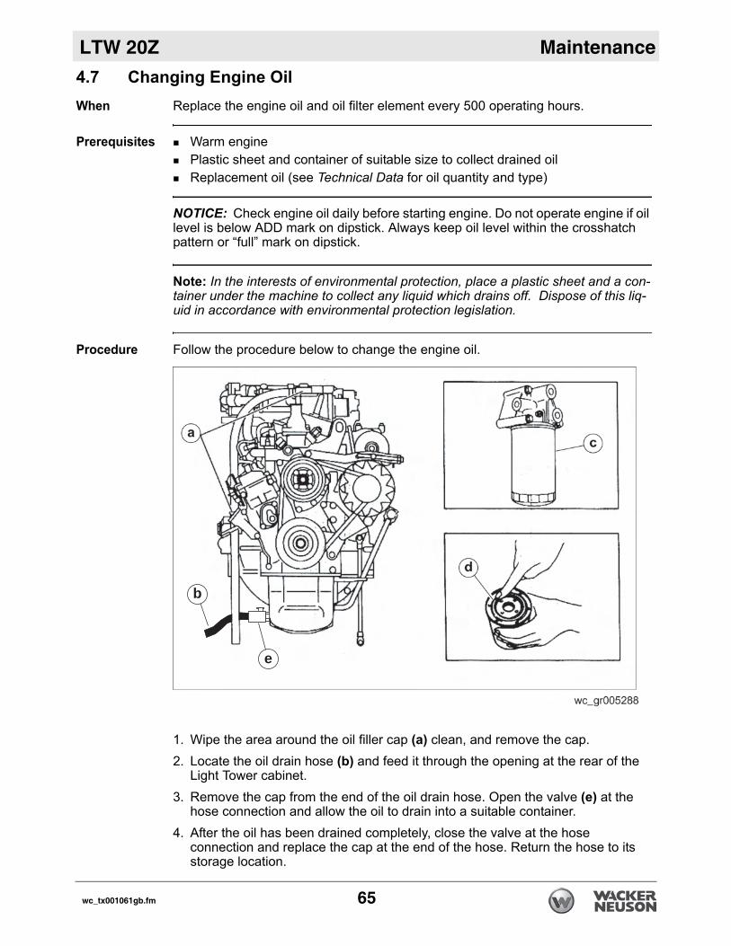
4.7 Changing Engine OilWhen Replace the engine oil and oil filter element every 500 operating hours.Prerequisites Warm enginePlastic sheet and container of suitable size to collect drained oilReplacement oil (see Technical Data for oil quantity and type)
NOTICE: Check engine oil daily before starting engine. Do not operate engine if oil level is below ADD mark on dipstick. Always keep oil level within the crosshatch pattern or “full” mark on dipstick.
Note: In the interests of environmental protection, place a plastic sheet and a con-tainer under the machine to collect any liquid which drains off. Dispose of this liq-uid in accordance with environmental protection legislation.
Procedure Follow the procedure below to change the engine oil.
1. Wipe the area around the oil filler cap (a) clean, and remove the cap.2. Locate the oil drain hose (b) and feed it through the opening at the rear of the
Light Tower cabinet.3. Remove the cap from the end of the oil drain hose. Open the valve (e) at the
hose connection and allow the oil to drain into a suitable container.4. After the oil has been drained completely, close the valve at the hose
connection and replace the cap at the end of the hose. Return the hose to its storage location.
e
b
wc_tx001061gb.fm 65
Maintenance LTW 20Z
5. Fill the engine crankcase through the oil filler opening to the upper mark on thedipstick. See Technical Data for oil quantity and type.6. Re-install the oil filter cap.
Replacing the oil filter element
Follow the procedure below to replace the oil filter element.
1. Use a filter wrench to remove the oil filter element (c). Discard the used element.
2. Apply a thin coat of oil to the O-ring on the new element (d).3. Hand-tighten the element until its sealed face comes in contact with the O-ring.4. Use a filter wrench to tighten the new element. Torque to 14.7–20.6 Nm
(10.8–15.2 ft.lbs).
WARNINGMost used oil contains small amounts of materials that can cause cancer and other health problems if inhaled, ingested, or left in contact with skin for prolonged peri-ods of time.
Take steps to avoid inhaling or ingesting used engine oil. Wash skin thoroughly after exposure to used engine oil.
66 wc_tx001061gb.fm

LTW 20Z Maintenance
4.8 Maintaining the Fuel/Water SeparatorWhen Empty the separator water bowl as needed.Change the separator element each time the fuel filter is changed—approximately every 250 hours of operation.
Prerequisites Container of suitable size to drain water from the separator elementReplacement separator element
Emptying the separator bowl
Follow the procedure below to empty the separator bowl (a). 1. Open the water bowl drain (b).
2. Allow the water to drain into a suitable container.3. Close the water bowl drain.
Changing the separator element
Follow the procedure below to change the separator element.
1. Loosen the element retainer (d).2. Remove the element retainer and element (c) from the separator head.3. Unscrew the separator bowl from the element.4. Screw the separator bowl onto the replacement element.5. Insert the retainer and replacement element into the separator head.6. Tighten the element retainer.The procedure is now complete.
4.9 Maintaining the TrailerTires Keep tires inflated to the proper pressure as shown on the tire sidewall.
Check tread periodically for wear.Replace tires as required.
Wheels Check that lug nuts holding wheels are tight. Replace any missing lug nuts immediately.
wc_gr006235
d
dba
wc_tx001061gb.fm 67

Maintenance LTW 20Z
4.10 Long-Term StorageIntroduction Extended storage of equipment requires preventative maintenance. Performingthese steps helps to preserve machine components and ensures the machine will be ready for future use. While not all of these steps necessarily apply to this machine, the basic procedures remain the same.
When Prepare your machine for extended storage if it will not be operated for 30 days or more.
Preparing for storage
Follow the procedures below to prepare your machine for storage.Complete any needed repairs.Replenish or change oils (engine, exciter, hydraulic & gear-case) per the intervals specified in the Scheduled Maintenance table. Grease all fittings and, if applicable, repack bearings.Inspect engine coolant. Replace coolant if it appears cloudy, is more than two seasons old, or does not meet the average lowest temperature for your area.If your machine has an engine equipped with a fuel valve, start the engine, close the fuel valve, and run the engine until it stops.Consult the engine owner’s manual for instructions on preparing the engine for storage.
Stabilizing the fuel
After completing the procedures listed above, fill the fuel tank completely and add a high-quality stabilizer to the fuel.
Choose a stabilizer that includes cleaning agents and additives designed to coat/protect the cylinder walls.Make sure the stabilizer you use is compatible with the fuel in your area, fuel type, grade and temperature range. Do not add extra alcohol to fuels which already contain it (for example, E10).For engines with diesel fuel, use a stabilizer with a biocide to restrict or prevent bacteria and fungus growth.Add the correct amount of stabilizer per the manufacturer’s recommendations.
Storing the machine
Perform these remaining steps to store your machine.Wash the machine and allow it to dry.Move the machine to a clean, dry, secure storage location. Block or chock wheels to prevent machine movement.Use touch-up paint as needed to protect exposed metal against rust. If the machine has a battery, either remove or disconnect it.
NOTICE: Allowing the battery to freeze or completely discharge is likely to cause permanent damage. Periodically charge the battery while the machine is not in use. In cold climates, store and charge the battery indoors or in a warm location.
Cover the machine. Tires and other exposed rubber items should be protected from the weather. Either cover them or use a readily available protectant.
68 wc_tx001061gb.fm

LTW 20Z Maintenance
4.11 TroubleshootingDANGERHigh voltage! This machine uses high voltage circuits capable of causing serious injury or death.
Only a qualified electrician should troubleshoot or repair electrical problems occurring in this equipment.
Problem / Symptom Reason Remedy
Lamp will not light Lamp is too hot Allow lamp to cool 10–15 minutes before restarting.
Faulty lamp connection Check that lamp is tight in socket. Check connections inside connection boxes on light fixtures and tower.
Lamp broken or burned out Check for:broken arc tube or outer lamp jacketbroken or loose components in lamp envelopeblackening or deposits inside lamp tube.
Circuit breaker turned on Turn off circuit breaker.
Circuit breaker loose or defective
Have a licensed electrician repair or replace the circuit breaker.
Generator output incorrect Check incoming voltage to ballast. Incoming voltage should be 120V ± 5V. If voltage is incorrect, engine speed may need to be adjusted or generator may require service.
Low or no ballast output With the fixture cord removed from its receptacle, the voltage should mea-sure 400 to 445 VAC. If proper voltage is not achieved, perform capacitor check to determine if capacitor or coil needs to be replaced.
Low light output Lamp degraded Replace lamp due to normal lamp life.
Low ballast output Check ballast for proper voltage out-put.
Fixture or lens dirty Clean reflective surface inside fixture and both inside and outside surface of glass lens.
wc_tx001061gb.fm 69
Factory-Installed Options LTW 20Z
5 Factory-Installed OptionsThis machine may be equipped with one or more of the following factory-installed options. To verify if any of these options are installed on your machine, contact Wacker Neuson Corporation at 1-800-770-0957. A nameplate listing the Model Number, Item Number, Revision, and Serial Number is attached to each unit. Please have this information available when contacting Wacker Neuson Corporation.The illustrations shown in this chapter represent typical installations. The factory-installed options on your machine may look different.
5.1 General OptionsAbout Brakes Your machine may be equipped with electric brakes or surge brakes. See Towing
Safety for more information about connecting and checking the brakes.
Electric Brakes
Machines equipped with electric brakes draw power from the tow vehicle. An electrical wiring harness connects the tow vehicle’s brake pedal to the brake actuators on the trailer. Pressing the brake pedal applies the brakes to both the tow vehicle and the trailer.
Surge Brakes Machines equipped with hydraulic surge brakes do not require any electrical connection to the tow vehicle. The braking system is completely self-contained, using momentum to actuate the trailer’s brake master cylinder and apply the brakes when the tow vehicle slows or stops.
Internal Light Storage
This option allows the light fixtures to be detached from the tower and stored inside the Light Tower cabinet. Internal storage protects the fixtures from damage on the job site, during transport, or during long-term storage.
Prerequisites Machine is shut downLeft side of Light Tower cabinet is open
70 wc_tx001266gb.fm

LTW 20Z Factory-Installed Options
b
d
c
a
e
f
3 4
1 2
wc_gr005287
wc_tx001266gb.fm 71

Factory-Installed Options LTW 20Z
Procedure Follow the procedure below to store the light fixtures.1. Rotate the two retaining wires (a) forward so that they lie flat in an open position.2. Disconnect the electrical cables (b) from the junction box (c).3. Detach light fixture #2 from the tower by removing the swivel handle (d) from the
threaded stud and lifting the fixture off the tower.
Note: Reinstall the swivel handle on the threaded stud after detaching the fixture.
4. Orient light fixture #2 so that the lens is facing you and the mounting bracket is on the top side. Place the fixture behind the left-hand divider (e) inside the light tower cabinet.
NOTICE: Avoid pinching the electrical cables beneath the fixtures or between the fixtures and dividers.
5. Repeat this procedure with light fixture #4, placing it behind the right-hand divider inside the light tower cabinet.
6. Rotate the retaining wires upward so that they rest against the lens frames.7. Detach and remove light fixture #1. 8. Orient light fixture #1 so that the lens is facing away from you and the mounting
bracket is on the bottom side. Place the fixture in front of the right-hand divider, resting it against the retaining wire (f).
9. Repeat this procedure with light fixture #3, placing it in the left-hand divider.10.Use the tie-down straps (g) to secure the fixtures in place. Each pair of fixtures
is secured with one strap. Tighten the strap across the top surface of the outer fixture and close the buckle to fasten the strap in place.
Note: Make sure to hook the tie-down straps in the cutouts provided for this purpose (h).
72 wc_tx001266gb.fm

LTW 20Z Factory-Installed Options
Cold Weather ShroudsMachines equipped with cold weather shrouds (a, b) are designed to operate optimally in cold weather environments.
Machines equipped with cold weather shrouds can be operated at full load in ambient temperatures up to 35°C (95°F). At ambient temperatures above 35°C (95°F), machines must be derated accordingly.
Engine Block Heater Option
The engine block heater option includes a block heater (a) with a cord (b).The function of the block heater is to heat the engine coolant/ engine blockto improve cold-weather engine starting. Plug the cord into a 120V powersupply.
Containment System
Overspills and leaks are captured in the containment system. Thecontainment system holds over 110% of the fluid contained in the machine. The containment system should be checked every 50 hours or 2 weeks anddrained when necessary. If fluid is found in the containment tank, trace thecause of the leak and correct.Note: In the interests of environmental protection, place impermeablesheeting and a container under the machine to collect the liquid which drainsoff. Dispose of this liquid in accordance with environmental protectionlegislation.
wc_gr006978
b
a
wc_gr006975
a
b
wc_tx001266gb.fm 73

Factory-Installed Options LTW 20Z
Lockable Battery Disconnect
A lockable ON/OFF switch is available which disconnects the battery. A padlock (not included) securely locks the switch in the OFF position. If equipped, the battery disconnect switch is mounted to the skid beneath the access door on the right side of the machine.NOTICE: Do not use the battery disconnect switch while the engine is running. Damage to electrical components may occur.
Battery Charger
An optional battery charger maintains the battery at peak power while themachine is turned off. Use of a battery charger is recommended when thegenerator is not operated on a regular basis. The battery charger preventsvoltage drain and reduces the possibility of having to jump-start the engineafter long periods of inactivity. Plug the cord into a 120V power supply.
wc_gr005779
74 wc_tx001266gb.fm

LTW 20Z Factory-Installed Options
5.2 Cold Weather OptionsCold Weather machines include the following options:Containment systemCold weather shroudsElectric brakesElectronic governorEngine block heaterBattery disconnectInternal light storageBattery charger
5.3 North Slope OptionsNorth Slope machines include the following options:
Containment systemElectric brakes or surge brakesManual winch or power winchElectronic governorEngine block heaterBattery charger
Additional options included with North Slope machines:
Quad Outlet Box
North Slope machines are equipped with an internal 4" receptacle box (a). This box functions as a central location to plug in cold weather accessories such as an engine block heater, oil pan heater, battery blanket, and battery charger. An electrical cord (b) allows the receptacle box to be directly connected to an external power source.
wc_gr006977
a
b
wc_tx001266gb.fm 75

Factory-Installed Options LTW 20Z
Rear Hitch wiith Containment SystemCertain models of the LTW are equipped with a 2" hitch receiver at the rear of the containment skid. This option enables the operator to tow auxiliary equipment behind the LTW.
When using the 2" hitch receiver to tow auxiliary equipment:Review topic Towing Safety for information on safe towing techniques.Do not tow more than two units.Do not tow on the highway.Do not exceed 55 kph (35 mph).Do not exceed the maximum Gross Vehicle Weight Rating (GVWR) of 1588 kg (3500 lbs).Do not exceed the maximum tongue weight of 240 kg (404 lbs).
Battery Blanket
An electrically powered blanket (a) warms the battery while the machine is not in use. The blanket eliminates engine starting difficulties caused by a cold, frozen, or discharged battery. Plug the cord into a 120V power supply.
wc_gr006976
WARNINGPossibility of personal injury or equipment damage from improper towing. Towing equipment, especially in tandem, requires careful preparation, appropriate equip-ment, and observance of maximum weights and towing speeds.
Follow the instructions below when towing auxiliary equipment behind the LTW.
wc_gr007422
a
76 wc_tx001266gb.fm

LTW 20Z Factory-Installed Options
Oil Pan Heater Cold, thick engine oil does not flow freely and may cause engine startingdifficulties. An oil pan heater installed on the engine oil pan keeps the oil warm and flowing. Heat from this electrical device warms the supply of engine oil contained in the pan while the machine is not in use. Plug the cord into a 120V power supply.
Fire Extinguisher and First Aid Kit
The North Slope machine is equipped with a fire extinguisher (b) and a first aid kit (c) for operator convenience and safety in the field.
Quick Connect Oil Drain System
The oil drain hose is located inside the Light Tower cabinet. North Slope machines are equipped with a quick connect fitting at the end of the hose.
Containment Suction Access Point
A vertical pipe (e) with a 3/4" NPT thread is provided next to the battery on the control panel side of the machine. The pipe extends into the containment skid tank, enabling suction cleanout of the tank.
wc_gr007423
c b
WARNINGMachine damage or burn hazards.
Before each machine startup, always make sure the fire extinguisher is fully charged, accessible, and undamaged.Train machine operators in the proper use of the fire extinguisher.
e
wc_gr007424
wc_tx001266gb.fm 77

Technical Data LTW 20Z
6 Technical Data6.1 EngineEngine Power Rating
Gross standby power rating per ISO 8528-1 and SAE J1995. Actual power output may vary due to conditions of specific use.
Machine LTW 20Z-1 LTW 20Z-3
Engine
Engine make / type Isuzu
Model 4LE2-NYGV02, Tier IVi
Number of cylinders 4
Displacement cm3 (in3) 2179 (133)
Operating speed rpm 1800
Rated standby power @ rated speed kW(Hp) 25.6 (34.3) @ 1800 rpm
Coolant capacity l (qts.) 11.3 (11.9)
Oil capacity l (qts.) 8.0 (8.5)
Battery Volts/CCa(standard)
(custom)12/75012/950
Fuel type Diesel
Fuel tank capacity l (gal.) 215.8 (57)
Fuel consumption, prime load l/hr (gal./hr) 5.97 (1.58)
Running time, prime load Hours 34.8
wc_td000310gb.fm78

LTW 20Z Technical Data
6.2 GeneratorMachine LTW 20Z-1 LTW 20Z-3
Generator
Make/Type Mecc Alte / Brushless
Model ECO 28-VL/4
Frequency 60 Hz
Generator speed rpm 1800
Prime Output kW(kVA)
18.6(23.3)
19.5(24.4)
AC voltage output V/phase 120/240, 1Ø 120, 1Ø208, 3Ø
Amps A 155/78 68 (x3)68
Excitation type AVR
Power factor 1.0 1Ø—1.03Ø—0.8
Voltage regulation ±1.00%
Insulation class H
wc_td000310gb.fm79
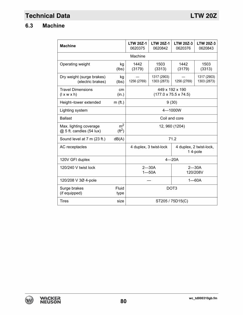
Technical Data LTW 20Z
6.3 MachineMachine LTW 20Z-10620375
LTW 20Z-10620842
LTW 20Z-30620376
LTW 20Z-30620843
Machine
Operating weight kg(lbs)
1442 (3179)
1503 (3313)
1442 (3179)
1503 (3313)
Dry weight (surge brakes) (electric brakes)
kg(lbs)
—1256 (2769)
1317 (2903)1303 (2873)
—1256 (2769)
1317 (2903)1303 (2873)
Travel Dimensions (l x w x h)
cm(in.)
449 x 192 x 190(177.0 x 75.5 x 74.5)
Height–tower extended m (ft.) 9 (30)
Lighting system 4—1000W
Ballast Coil and core
Max. lighting coverage@ 5 ft. candles (54 lux)
m2
(ft2)12, 960 (1204)
Sound level at 7 m (23 ft.) dB(A) 71.2
AC receptacles 4 duplex, 3 twist-lock 4 duplex, 2 twist-lock,1 4-pole
120V GFI duplex 4—20A
120/240 V twist lock 2—30A 1—50A
2—30A 120/208V
120/208 V 3Ø 4-pole — 1—60A
Surge brakes(if equipped)
Fluidtype
DOT3
Tires size ST205 / 75D15(C)
wc_td000310gb.fm80

LTW 20Z Technical Data
6.4 Dimensions6.5 Radiation ComplianceThis machine meets the radio interference radiated emission requirements of European Standard EN 13309 for Construction Machinery.
The lamps provided with this machine are electric discharge lamps. They are designed for use with metal halide ballasts only, and require time to reach full brightness on initial startup and after a power interruption. These lamps comply with FDA regulation performance standards 21 CFR 1040-30
wc_gr006326
192 (75.5)
190 (74.5)
313 (123.0)449 (177.0)
mm (in.)
wc_td000310gb.fm81

Technical Data LTW 20Z
Notes:wc_td000310gb.fm82

Schematics
ft blank.
LTW 20Z
wc_tx001064gb.fm 83
7 Schematics
This page is intentionally le

LTW 20Z
008801wc_gr008801
g
g
g
g
w xv
wv
wv
wv
t t
sl
u
Schematics
84
7.1 LTW 20Z-1—Electrical Schematic
b
z
c
e
ha
y
k
f
j
n
m
n
m
n
m
n
m o
p
o
p
q
r
d

Schematics
s
L Yellow OR Orange
R Brown PU Purple
L Clear SH Shield
Y Gray LB Lt. blue
LTW 20Z
wc_tx001064gb.fm 85
7.2 LTW 20Z-1—Electrical Schematic Components
Ref. Description Ref. Description
a Generator o Receptacle, 120/240V 30 Amp
b Generator junction box p Circuit breaker, 240V 30 Amp
c Voltage regulator q Receptacle, 120/240V 50 Amp
d Exciter r Circuit breaker, 240V 50 Amp
e Stator (aux winding) s Control box
f Stator (main winding) t Terminal strip
g Circuit breaker, 120V 15 Amp u Control box ground
h Control box front panel v Transformer
j Engine controller w Capacitor
k Main breaker, 80 Amp x Lights
l Receptacle box y Fuse, 120V 2 Amp
m Receptacle, 120V 20 Amp GFCI z Generator connection block
n Circuit breaker, 120V 20 Amp — —
Wire Color
BK Black RD Red Y
GN Green TN Tan B
BU Blue VIO Violet C
PK Pink WH White G

LTW 20Z
BUBU
44
BKBK
RDRD
YLYL
22
YLYL
YLYL
BK/YLBK/YL
11
YLYL
YLYL
33
BK/YLBK/YL
BK/YLBK/YL
BK/YLBK/YL
YLYL
YLYL
21-B
K 1
6 AW
G21
-BK
16
AWG
BRBR OROR PUPU WW YLYLYLYLYLYLYLYL YLYL YLYLYLYLYLYL
5A-GN/YL 10 AWG5A-GN/YL 10 AWG
5-GN/YL 10 AWG5-GN/YL 10 AWG
GNGN
2-BK
10
AWG
2-BK
10
AWG
2A-B
K 1
0 AW
G2A
-BK
10
AWG
70-BK 8 AWG70-BK 8 AWG
N4A-
WH
10 A
WG
N4A-
WH
10 A
WG
N4-W
H 10
AW
GN4
-WH
10 A
WG
4A-B
U 10
AW
G4A
-BU
10 A
WG
YLYL
YLYL
6-BK
14
AWG
6-BK
14
AWG
7-BK
14
AWG
7-BK
14
AWG
8-BK
14
AWG
8-BK
14
AWG
9-BK
14
AWG
9-BK
14
AWG
1-BK
10
AWG
1-BK
10
AWG
1A-B
K 1
0 AW
G1A
-BK
10
AWG
44
22
11
33
3-BK
10
AWG
3-BK
10
AWG
3A-B
K 1
0 AW
G3A
-BK
10
AWG
12-BK 10 AWG12-BK 10 AWG
14-BK 14 AWG14-BK 14 AWG13-BK 14 AWG13-BK 14 AWG
22-BK 10 AWG22-BK 10 AWG
23-BK 10 AWG23-BK 10 AWG
32-BK 10 AWG32-BK 10 AWG
33-BK 14 AWG33-BK 14 AWG34-BK 14 AWG34-BK 14 AWG
41-BU 10 AWG41-BU 10 AWG41A-BU 10 AWG41A-BU 10 AWG
42-BU 10 AWG42-BU 10 AWG43-BU 14 AWG43-BU 14 AWG
51A-GN/YL 10 AWG51A-GN/YL 10 AWG51-GN/YL 10 AWG51-GN/YL 10 AWG
52-GN/YL 10 AWG52-GN/YL 10 AWG
53-G
N/YL
14
AWG
53-G
N/YL
14
AWG
54-G
N/YL
14
AWG
54-G
N/YL
14
AWG
11-BK 10 AWG11-BK 10 AWG
11A-BK 10 AWG11A-BK 10 AWG
1-BK 10 AWG1-BK 10 AWG
4-BU 10 AWG4-BU 10 AWG4A-BU 10 AWG4A-BU 10 AWG45-BU 10 AWG45-BU 10 AWG46-BU 14 AWG46-BU 14 AWG5-GN/YL 10 AWG5-GN/YL 10 AWG5A-GN/YL 10 AWG5A-GN/YL 10 AWG
55-GN/YL 10 AWG55-GN/YL 10 AWG
57-G
N/YL
14
AWG
57-G
N/YL
14
AWG
56-G
N/YL
14
AWG
56-G
N/YL
14
AWG
1A-BK 10 AWG1A-BK 10 AWG
21-BK 10 AWG21-BK 10 AWG
21A-BK 10 AWG21A-BK 10 AWG
2-BK 10 AWG2-BK 10 AWG
2A-BK 10 AWG2A-BK 10 AWG31-BK 10 AWG31-BK 10 AWG
31A-BK 10 AWG31A-BK 10 AWG
3-BK 10 AWG3-BK 10 AWG
3A-BK 10 AWG3A-BK 10 AWG
4-BU
10
AWG
4-BU
10
AWG
71-BK 8 AWG71-BK 8 AWG
N4-W
H 1
0 AW
GN4
-WH
10
AWG
N4A-
WH
10
AWG
N4A-
WH
10
AWG
BK/YLBK/YL
BK/YLBK/YL
BK/YLBK/YL
BK/YLBK/YL
21-B
K 1
6 AW
G21
-BK
16
AWG
22
GNGNWWGNGN BKBK
44
WW BKBK
GNGNWWGNGN BKBK
11
WW
33
BKBK
PUPU
WW
OROR
BRBR
GNGN
BUBU
BKBK
RDRD
YLYL
g
g
g
g
w xv
wv
wv
wv
t
t
sl
u
wc_gr007963
Schematics
86
7.3 LTW 20Z-3—Electrical Schematic
15A-
BK15
A-BK
15-B
K15
-BK
21-B
K 1
6 AW
G21
-BK
16
AWG
20-B
K 1
6 AW
G20
-BK
16
AWG
1-BK
10
AWG
1-BK
10
AWG
1A-B
K 10
AW
G1A
-BK
10 A
WG
6-BK
14
AWG
6-BK
14
AWG
11A-
BK 1
0 AW
G11
A-BK
10
AWG
22-B
K 10
AW
G22
-BK
10 A
WG
12-B
K 10
AW
G12
-BK
10 A
WG
13-B
K 14
AW
G13
-BK
14 A
WG
N4-WH 10 AWGN4-WH 10 AWGN4A-WH 10 AWGN4A-WH 10 AWG
XX
YY
GG XX
YY
GG
22
NN
11
33
1133557799
1111
22446688
L2-BK 10 AWGL2-BK 10 AWGL2A-BK 10 AWGL2A-BK 10 AWG
L1A-BK 10 AWGL1A-BK 10 AWGL1-BK 10 AWGL1-BK 10 AWG
YL (+)YL (+)BU (-)BU (-)
RDRD
ROTORROTOR STATORSTATOR
RECTIFIERRECTIFIER
ROTORROTORMAINMAINFIELDFIELD
10101212
GN (SENSING)GN (SENSING)
GN (SENSING)GN (SENSING)
21212020
NCNC
NONO
CC
DUAL COILDUAL COIL
AUXAUXSWITCHSWITCH
L2-B
K 10
AW
GL2
-BK
10 A
WG
L2A-
BK 1
0 AW
GL2
A-BK
10
AWG
L1A-
BK 1
0 AW
GL1
A-BK
10
AWG
LI-B
K 10
AW
GLI
-BK
10 A
WG
20-B
K 16
AW
G20
-BK
16 A
WG
GG
L3-B
K 10
AW
GL3
-BK
10 A
WG
L3A-
BK 1
0 AW
GL3
A-BK
10
AWG
L3-BK 10 AWGL3-BK 10 AWGL3A-BK 10 AWGL3A-BK 10 AWG
11-B
K 10
AW
G11
-BK
10 A
WG
21A-
BK 1
0 AW
G21
A-BK
10
AWG
21-B
K 10
AW
G21
-BK
10 A
WG
31A-
BK 1
0 AW
G31
A-BK
10
AWG
31-B
K 10
AW
G31
-BK
10 A
WG
25A-
BK25
A-BK
25-B
K25
-BK
35A-
BK35
A-BK
35-B
K35
-BK
10 A
WG
10 A
WG
10 A
WG
10 A
WG
10 A
WG
10 A
WG
10 A
WG
10 A
WG
32-B
K 10
AW
G32
-BK
10 A
WG
23-B
K 10
AW
G23
-BK
10 A
WG
14-B
K 14
AW
G14
-BK
14 A
WG
33-B
K 14
AW
G33
-BK
14 A
WG
34-B
K 14
AW
G34
-BK
14 A
WG
47-B
U 14
AW
G47
-BU
14 A
WG
44-B
U44
-BU
14 A
WG
14 A
WG
47-B
U 14
AW
G47
-BU
14 A
WG
46-B
U 14
AW
G46
-BU
14 A
WG
42-B
U42
-BU
10 A
WG
10 A
WG
44-B
U 14
AW
G44
-BU
14 A
WG
43-B
U 14
AW
G43
-BU
14 A
WG
52-G
N/YL
52-G
N/YL
10 A
WG
10 A
WG
45-B
U45
-BU
10 A
WG
10 A
WG
55-G
N/YL
55-G
N/YL
10 A
WG
10 A
WG
51A-
GN/Y
L51
A-GN
/YL
51-G
N/YL
51-G
N/YL
41A-BU 10 AWG41A-BU 10 AWG 41-BU 10 AWG41-BU 10 AWG
2-BK
10
AWG
2-BK
10
AWG
2A-B
K 10
AW
G2A
-BK
10 A
WG
8-BK
14
AWG
8-BK
14
AWG
3-BK
10
AWG
3-BK
10
AWG
3A-B
K 10
AW
G3A
-BK
10 A
WG
9-BK
14
AWG
9-BK
14
AWG
10 AWG10 AWG 10 AWG10 AWG
10AW
G10
AWG
10AW
G10
AWG
53-G
N/YL
14
AWG
53-G
N/YL
14
AWG
56-G
N/YL
14
AWG
56-G
N/YL
14
AWG
54-G
N/YL
54-G
N/YL
57-G
N/YL
14
AWG
57-G
N/YL
14
AWG
14 AWG14 AWG
38-BK38-BK14 AWG14 AWG
16-BK16-BK10 AWG10 AWG
24-BK24-BK10 AWG10 AWG26-BK26-BK
10 AWG10 AWG
36-BK36-BK10 AWG10 AWG17-BK17-BK
14 AWG14 AWG18-BK18-BK
14 AWG14 AWG37-BK37-BK
14 AWG14 AWG
11 22 33 44 55 66
60 Hz60 HzJUMPERJUMPER
YL (+)YL (+)
BU (-)BU (-)
GN (SENSING)GN (SENSING)
GNGN
BK (NEUTRAL)BK (NEUTRAL)
BKBK
GNGNGNGNGNGN GNGN
RDRD
bb
c
z
aaaa
e
ha
y
k
f
j
n
m
n
m
n
m
n
m o
p
o
p
q
r
d

Schematics
s
L Yellow OR Orange
R Brown PU Purple
L Clear SH Shield
Y Gray LB Lt. blue
LTW 20Z
wc_tx001064gb.fm 87
7.4 LTW 20Z-3—Electrical Schematic Components
Ref. Description Ref. Description
a Generator o Receptacle, 120/208V 30 Amp
b Generator junction box p Circuit breaker, 120/208V 30 Amp
c Voltage regulator q Receptacle, 120/208 60A 3Ø
d Exciter r Circuit breaker, 120/208V 60A 3Ø
e Stator (aux winding) s Control box
f Stator (main winding) t Terminal strip
g Circuit breaker, 120V 15 Amp u Control box ground
h Control box front panel v Transformer
j Engine controller w Capacitor
k Main breaker, 80 Amp x Lights
l Receptacle box y Fuse, 120V 2 Amp
m Receptacle, 120V 20 Amp GFCI z Generator connection block
n Circuit breaker, 120V 20 Amp aa Sensing module
Wire Color
BK Black RD Red Y
GN Green TN Tan B
BU Blue VIO Violet C
PK Pink WH White G

LTW 20Z
m
nq r
t
s
jo
p
wc_gr006501wc_gr006501
Schematics
88
7.5 Engine Wiring
bb
c g
lev
h
a k
f
u
d

Schematics
s
L Yellow OR Orange
R Brown PU Purple
L Clear SH Shield
Y Gray LB Lt. blue
LTW 20Z
wc_tx001064gb.fm 89
7.6 Engine Wiring Components
Ref. Description Ref. Description
a Emergency stop switch m Terminal block
b Control panel ground n Hour meter
c Engine controller o Starter motor
d Main breaker p Alternator
e Engine ground q Fuel pump relay
f Control box ground r Starter relay
g Oil pressure sensor s Glow plug relay
h Water temperature sensor t Glow plugs
j Fuel pump u Fuel solenoid
k Fuse box v Battery disconnect (if equipped)
l Battery
Wire Color
BK Black RD Red Y
GN Green TN Tan B
BU Blue VIO Violet C
PK Pink WH White G

LTW 20Z
47-WH
6-BR
2-GN
W
B
G
WB
Y
44-WH64-BR
5-YL
wc_gr006979
j
k
re Colors
YL Yellow OR Orange
BR Brown PU Purple
CL Clear SH Shield
GY Gray LB Lt. blue
Schematics
90
7.7 Trailer Wiring (Electric Brakes)
7.8 Trailer Wiring Components (Electric Brakes)
Ref. Description Ref. Description
a Main trailer plug f Left brake
b Breakaway switch g Front right side light
c Battery charger h Front left side light
d Breakaway battery j Rear right tail light
e Right brake k Rear left tail light
47-WH6-BR5-YL2-GN
46-W
H
66-B
R
5-W
H
6-BR
45-W
H
65-B
RB B
B B
47-WH6-BR5-YL
2-GN
4-WH 12GA6-BR5-YL2-GN
1-RD 12GA3-BU 12GA
34-BU 34-BU33-BU
43-W
H
BKBKRDRD
31-B
U41
-WH
32-B
U42
-WH
3-BU 12GA
4-WH 12GA
4-WH 12GA
BKBK
a
c
d
e
h
g
f
b
Wi
BK Black RD Red
GN Green TN Tan
BU Blue VIO Violet
PK Pink WH White

Schematics
s
L Yellow OR Orange
R Brown PU Purple
L Clear SH Shield
Y Gray LB Lt. blue
LTW 20Z
wc_tx001064gb.fm 91
7.9 Trailer Wiring (Surge Brakes / No Brakes)
Wire Color
BK Black RD Red Y
GN Green TN Tan B
BU Blue VIO Violet C
PK Pink WH White G
wc_gr006237
GN
YL
BR
BR
WH
WH
GN
YL
BR
BR
WH
WH
BKBK
GNYLBRWH
BKBK


Wacker Neuson Produktion GmbH & Co. KG, Preußenstraße 41, D-80809 München, Tel.: +49-(0)89-3 54 02-0 Fax: +49 - (0)89-3 54 02-390Wacker Neuson Production Americas LLC, N92W15000 Anthony Ave., Menomonee Falls, WI 53051
Tel. : (262) 255-0500 Fax: (262) 255-0550 Tel.: (800) 770-0957Wacker Neuson Limited - Room 1701–03 & 1717–20, 17/F. Tower 1, Grand Century Place, 193 Prince Edward Road West, Mongkok, Kowloon, Hongkong.
Tel: (852) 3605 5360, Fax: (852) 2758 0032