OPERATOR'S MANUAL II:RRFTSMRN ICheck for alignment of moving parts, binding of moving parts,...
20
OPERATOR'S MANUAL II:RRFTSMRN I ROUTER DOVETAIL JOINT TEMPLATE KIT MODEL NO. 315.25791 FOR USE WITH ROUTERS WITH 3-HOLE TEMPLATE GUIDE MOUNT, _ WARNING: To reduce the risk of injury, the user must read and understand the operator's manual before using this product. Customer Help Line: t-800-932-3188 Sears, Roebuck and Co., 3333 Beverly Rd., Hoffman Estates, IL 60179 USA Visit the Craftsman web page: www.sears.com/craftsman 983000-533 9-04 Save this manual for future reference
Transcript of OPERATOR'S MANUAL II:RRFTSMRN ICheck for alignment of moving parts, binding of moving parts,...

OPERATOR'S MANUAL
II:RRFTSMRN IROUTER DOVETAIL JOINTTEMPLATE KIT
MODEL NO.315.25791
FOR USE WITH ROUTERS WITH3-HOLE TEMPLATE GUIDE MOUNT,
_ WARNING: To reduce the risk of injury,the user must read and understand the
operator's manual before using this product.
Customer Help Line: t-800-932-3188
Sears, Roebuck and Co., 3333 Beverly Rd., Hoffman Estates, IL 60179 USA
Visit the Craftsman web page: www.sears.com/craftsman
983000-5339-04
Save this manual for future reference

• Introduction ..................................................................................................................................................................... 2
• General Safety Rules ....................................................................................................................................................... 3
• Symbols ........................................................................................................................................................................... 4
• Assembly ......................................................................................................................................................................... 5
• Operation .................................................................................................................................................................... 6-18
• Troubleshooting ............................................................................................................................................................. 18
• Exploded View and Parts List ................................................................................................................................... 19-20
• Parts Ordering/Service ..................................................................................................................................... Back Page
This accessory has many features for making its use more pleasant and enjoyable. Safety, performance, anddependability have been given top priority in the design of this product making it easy to maintain and operate.

_L ARNING: read and understand all instructions.Failure to follow all instructions listed below, mayresult in electric shock, fire and/or serious personalinjury.
SAVE THESE INSTRUCTIONS
• Read these instructions and the instructions foryour router thoroughly before using accessory.
• Know your power tool. Read the operator's manualfor your router carefully. Learn the router's app(icationsand limitations as well as the specific potential hazardsrelated to this tool.
• Always wear safety glasses. Everyday eyeglasseshave only impact-resistant lenses; they are notsafety glasses. Following this rule will reduce the riskof serious personal injury.
• Always disconnect router from power supply beforemaking adjustments or adding accessories. Makesure the switch is off when reconnecting to power sup-ply.
• Keep your work area clean and well lit. Clutteredbenches and dark areas invite accidents.
• Do not operate power tools in explosive atmo-spheres, such as in the presence of flammable liq-uids, gases, or dust. Power tools create sparks whichmay ignite the dust or fumes.
• Keep bystanders, children, and visitors away whileoperating a power tool. Distractions can cause you tolose control.
• Stay alert, watch what you are doing and use com-mon sense when operating a power tool. Do notuse tool while tired or under the influence of drugs,alcohol, or medication. A moment of inattention whileoperating power tools may result in serious personalinjury.
• Avoid accidental starting. Be sure switch is offbefore plugging in. Carrying tools with your finger onthe switch or plugging in tools that have the switch oninvites accidents.
• Do not overreach. Keep proper footing and balanceat all times. Proper footing and balance enab(es bettercontrol of the tool in unexpected situations.
• Use clamps or other practical way to secure andsupport the workpiece to a stable platform. Holdingthe work by hand or against your body is unstable andmay lead to loss of control.
• Disconnect the plug from power source beforemaking any adjustments, changing accessories,or storing the tool. Such preventive safety measuresreduce the risk of starting the tool accidentally.
• Keep the tool and its handle dry, clean and freefrom oil and grease. Always use a clean cloth whencleaning. Never use brake fluids, gasoline, petroleum-based products, or any strong solvents to clean yourtool. Following this rule will reduce the risk of loss ofcontrol and deterioration of the enclosure plastic.
• Protect your lungs. Wear a face or dust mask if theoperation is dusty. Following this rule will reduce therisk of serious personal injury.
• Protect your hearing. Wear hearing protection dur-ing extended periods of operation, Following this rulewill reduce the risk of serious personal injury.
• Inspect tool cords periodically and, if damaged,have repaired at your nearest authorized servicecenter. Constantly stay aware of cord location. Fol-lowing this rule will reduce the risk of electric shock orfire.
• Check damaged parts. Before further use of thetool, a guard or other part that is damaged shouldbe carefully checked to determine that it will op-erate properly and perform its intended function.Check for alignment of moving parts, binding ofmoving parts, breakage of parts, mounting, andany other conditions that may affect its opera-tion. A guard or other part that is damaged shouldbe properly repaired or replaced by an authorizedservice center. Following this rule will reduce the riskof shock, fire, or serious injury.
• Inspect for and remove all nails from lumber beforeusing this tool. Following this rule will reduce the riskof serious personal injury.
• Save these instructions. Refer to them frequently anduse them to instruct others who may use this tool. Ifyou loan someone this tool, loan them these instruc-tions also.
_k WARNING: Some dust created by power sanding, sawing, grinding, drilling, and other construction activitiescontains chemicals known to cause cancer, birth defects or other reproductive harm. Some examples of thesechemicals are:
• lead from lead-based paints,
• crystalline silica from bricks and cement and other masonry products, and
• arsenic and chromium from chemically-treated lumber.
Your risk from these exposures varies, depending on how often you do this type of work. To reduce your exposureto these chemicals: work in a well ventilated area, and work with approved safety equipment, such as those dustmasks that are specially designed to filter out microscopic particles.
3

Thefollowingsignalwordsandmeaningsareintendedto explainthe levelsofriskassociatedwiththisproduct.
SYMBOL SIGNAL MEANING
,_ DANGER:Indicates an imminently hazardous situation, which, if not avoided, willresult in death or serious injury.
_k WARNING:Indicates a potentially hazardous situation, which, if not avoided, couldresult in death or serious injury.
,_ CAUTION:Indicates a potentially hazardous situation, which, if not avoided, mayresult in minor or moderate injury.
CAUTION: (Without Safety Alert Symbol) Indicates a situation that may result inproperty damage.
SERVICE
Servicing requires extreme care and knowledge andshould be performed only by a qualified service tech-nician. For service we suggest you return the product toyour nearest AUTHORIZED SERVICE CENTER for repair.When servicing, use only identical replacement parts.
A WARNING: To avoid serious personal injury, donot attempt to use this product until you readthoroughly and understand completely theoperator's manual. Save this operator's manualand review frequently for continuing safe opera-tion and instructing others who may use thisproduct.
,_ WARNING:
The operation of any power tool can result in foreign objects being thrown into your eyes, whichcan result in severe eye damage. Before beginning power tool operation, always wear safetygoggles or safety glasses with side shields and a full face shield when needed. We recommendWide Vision Safety Mask for use over eyeglasses or standard safety glasses with side shields.Always use eye protection which is marked to comply with ANSI Z87.1.
SAVE THESE INSTRUCTIONS

UNPACKING
This product requires assembly.
• Carefully remove all parts from the box. Make sure thatall items listed in the packing list are included.
• Inspect the parts carefully to make sure no breakage ordamage occurred during shipping.
• Do not discard the packing material until you have care-fully inspected and satisfactorily operated the acces-sory.
• If any parts are damaged or missing, please call1-800-932-3188 for assistance.
PACKING LIST
Item No, Description Qty.1 Dovetail Template and Base 12 Hex Bolt (1/4-20 x 3 in.) 43 Nut (1/4-20) 44 Spring 45 Washer 8
6 Clamp Bar 27 Clamping Knob 48 5/16 in. Guide Bushing 19 7/16 in. Guide Bushing 110 Screw (10-32 x 7/8 in. Flat Head) 311 Operator's Manual
_ WARNING: If any parts are missing do not operatethis accessory until the missing parts are replaced.Failure to do so could result in possible serious per-sonal injury.
A WARNING: Do not attempt to modify this acces-sory. Any such alteration or modification is misuseand could result in a hazardous condition leading topossible serious personal injury.
_IL WARNING: Do not connect router to power supplyuntil assembly is complete. Failure to comply couldresult in accidental starting and possible seriousinjury.
ASSEMBLING YOUR DOVETAIL TEMPLATESee Figure 1.
• Insert hex bolts through holes located at top and frontof dovetail base as shown in figure 1.
• Make sure the bolt head flats are lined up with slotsinside the dovetail base.
• Secure hex bolt with hex nuts supplied.
• Place one spring over each hex bolt.
• Place a washer on top of each spring, then installclamp bar on top of washer.
NOTE: For proper assembly, be sure to turn eachclamp bar as shown in Figure 1.
• Place a second washer on top and/or end of eachclamp bar.
• Thread a clamping knob onto each hex bolt to securewashers, clamp bars, and springs.
7\ _7
1\ .......... 3 .............. 9 _ 8
.......................... ,o
Fig. 1
TOOLS NEEDEDIn addition to the dovetail template and guide bushing,you will also need a Craftsman Router and a dovetail cut-ter. Use dovetail cutter Catalog Number 26319 for making1/4 in. dovetail joints and Catalog Number 26318, 25505for making 1/2 in. joints.

_ WARNING: Do not allow familiarity with toolsto make you careless. Remember that a carelessfraction of a second is sufficient to inflict serious
injury.
_ WARNING: Always wear safety goggles or safetyglasses with side shields when operating powertools. Failure to do so could result in objects beingthrown into your eyes resulting in possible seriousinjury.
A WARNING: Do not use any attachments or acces-sories not recommended by the manufacturer ofthis tool. The use of attachments or accessories notrecommended can result in serious personal injury.
APPLICATIONSYou may use this tool for the purposes listed below:See Figure 2.
• Cutting Flush Joints
• Cutting Offset Joints• Cutting Rabbeted Joints
Your router dovetail template kit has been designed forcutting flush, offset, or rabbeted joints with speed and ac-curacy. Since these joints are both strong and neat, theyare commonly used when making drawers and boxes.
Read all instructions carefully, and follow closely whilemaking set ups and adjustments.
FLUSH OFFSET RABBETEDJOINT JOINT JOINT
Fig. 2
NOTE: Once all adjustments have been properly made,make a trial cut with scrap pieces of the same wood usedfor the finished work.
This step allows you to check your adjustments. It alsomakes you aware of the characteristics of the particularwood being used.
MOUNTING DOVETAIL BASE
See Figures 3 - 4.
_ WARNING: For safe operation and propercontrol, your router dovetail template kit must bemounted to a workbench or table.
If desired, it can be clamped to a workbench with "C"clamps, or it can be mounted onto a 3/4 in. piece of ply-wood for mobility.
• Clamp the dovetail base to a workbench or tablewith "C" clamps. It can then be easily removed uponcompletion for easy storage or changing job sites.
CLAMP
C CLAMP
Fig. 3
A second, more preferred, method would be to mountyour dovetail base onto a piece of 3/4 in. plywoodapproximately six inches wide and twenty-four incheslong. Position front of base flush with the front andcentered with the ends of the board, then insert fourflat head wood screws through holes in the base andsecure firmly into plywood. The dovetail base (withwooden base) may then be clamped securely toworkbench or table with "C" clamps or other holdingapparatus. Here again, it can be easily removed uponcompletion for easy storage or changing job sites.
WOODSCREWS
C CLAMPPLYWOOD
Fig. 4

INSTALLING TEMPLATE GUIDE BUSHINGAND CUTTERSee Figure 5.
Two template guide bushings are supplied with the routerdovetail template kit. They are used to guide the router inand out of the fingers of the comb-shaped template. The5/16 in. bushing is used when making 1/4 in. dovetails,while the 7/16 in. bushing is used when making 1/2 in.dovetails.
_ WARNING: To avoid possible serious personalinjury, unplug the router while assembling parts ormaking adjustments.
• Attach guide bushing directly to the inside of the routersubbase.
NOTE: It is not necessary to remove subbase whileattaching guide bushing, but be sure collar section isturned facing away from the router motor.
• Secure bushing to the router subbase with the 3screws supplied.
• Insert dovetail cutter through guide bushing and intocollet at least 3/4 in. If 3/4 in. engagement does not ex-ist, lower the router motor in the router base until colletnut is approximately 1/8 in. clear of guide bushing.
• Tighten securely before attempting to center cutterinside guide bushing. If clamp is not tight, the routermotor will be loose and wobble inside router base whileadjustments are being made.
• Visually center the cutter with the inside diameter of theguide bushing, then tighten the collet nut securely.
NOTE: When centering cutter in guide bushing, adjust-ments can be made by loosening the screws holdingthe subbase to the router and/or loosening the screwsholding the guide bushing to the router.
• Tighten all screws securely.
BEGIN YOUR SET-UPSee Figure 6.
To begin your set-up, you will need to determine what thefinal dimensions for your drawer or box will be, then cutyour boards to size. If you plan in advance, try to size thedrawer opening so that a half-pin will be on both the topand bottom edge of the drawer front. See helpful hints,page 18. See the chart on page 8 for computing propersizes and recommended material thicknesses.
Next, decide whether you are going to make 1/4 in. or1/2 in. joints. The dovetail template is packaged with theangle brackets set for making 1/2 in. joints. If 1/4 in. jointsare desired, loosen the two screws holding the anglebrackets, and reverse them 180°. Re-tighten angle bracketscrews. Reverse the procedure when changing your tem-plate from 1/4 in. joints to 1/2 in. joints.
CLAMP
SUBBASE
SCREW _ SCREWS
DOVETAIL GUIDEBUSHINGCUTTER
Fig. 5
NOTE: Plan your drawer height opening so that theboards will be in increments of 7/8 in. for 1/2 in. joints, or29/64 in. increments for 1/4 in. joints. This will allow a half-pin to be on both the top and bottom edge of the drawerfront. Don't forget to allow for clearances.
ANGLEBRACKET
Fig. 6

DRAWERHEIGHTFRONTANDBACKSIDEWIDTH 12 in. MAX.
DRAWERWIDTH DRAWERBACKLENGTH LENGTH
FLUSHDRAWER
SIDELENGTH
HALF-PIN
OFFSETDRAWER
1/16 in.
DRAWERHEIGHTBACK
WIDTHSIDE
WIDTH
DRAWERWIDTHBACK
LENGTH
3/8 in.
FRONTLENGTH
3R in.
FRONTWIDTH
MAX.
3_ in.
DRAWERLENGTH
SIDELENGTH
RABBETEDDRAWER
Fig, 7
1/2 in. DOVETAIL JOINTS
RecommendedSection Length Width
Thickness
Back - Flush/Rabbeted 1/2 in. to 3/4 in. Width of opening less clearance Height of opening less clearance
Back - Offset 1/2 in. to 3/4 in. Front length minus 1/8 in. Height of opening less clearance
Sides 1/2 in. to 3/4 in. Must be determined for each job Same as backdepending on depth of opening,clearance, and thickness of front andback
Bottom 1/4 in. to 3/8 in. Length of side less 1/4 in. Length of back, plus 1/2 in. less 2times side thickness
Flush Front 1/2 in. to 3/4 in. Width of opening less clearance Same as Back
Offset-Front 1/2 in. to 3/4 in. Width of opening less clearance Same as Back
3/8 in. Rabbeted Front 3/4 in. Back Length plus 3/4 in. Back width plus 3/4 in.
NOTE: Front, back and sides should be grooved 1/4 in. deep to receive bottom piece and may be done before or after dovetailing. Ifgroove depth is more or less than 1/4 in., bottom dimensions must be altered to compensate.
1/4 in, DOVETAIL JOINTS
RecommendedSection Length Width
Thickness
Back - Rush/Rabbeted 5/16 in. to 3/4 in. Width of opening less clearance Height of opening less clearance
Back - Offset 5/16 in. to 3/4 in. Front length minus 1/8 in. Height of opening less clearance
Sides 1/4 in. to 1/2 in. Must be determined for each job Same as backdepending on depth of opening,clearance, and thickness of front andback
Bottom 1/4 in. Length of side less 1/4 in. Length of back, plus 1/2 in. less 2times side thickness
Flush Front 5/16 in. to 3/4 in. Width of opening less clearance Same as Back
Offset-Front 5/16 in. to 3/4 in. Width of opening less clearance Same as Back
3/8 in. Rabbeted Front 1/2 in. to 3/4 in. Back Length plus 3/4 in. Back width plus 3/4 in.
NOTE: Front, back and sides should be grooved 3/16 in. deep to receive bottom piece and may be done before or after dovetailing.If groove depth is more or less than 3/16 in., bottom dimensions must be altered to compensate.
8

REFERENCE GUIDE
See Figure 8.
The base of the router dovetail template kit has a label toserve as a guide for you to follow when making set-upsfor different types of joinery. Familiarize yourself with thislabel and refer to it as often as necessary.
FLUSH
OFFSET
_ABBETED
DOVETAIL TEMPLATE
17/32 in. FLUSH
17/32 in. OFFSET
17/32in. RABBETED
2
MODEL 315.25791 1/4 in. Tails
BIT I _STOP BRACKET I BfTDEPTH JOINT I TOP ISlUEI LOCATION DEPTH
C C 1 7/16 in.
C C 2 7/16 in.
R C 3 7/16 in.
3
1/2 in. TailsSTOP BRACKET
JOINT _ LOCATION
A A 1
A A 2
R A 3
1
Fig. 8
FLUSH FRONT DRAWER OR BOX
_ WARNING: Unplug router from power supplywhile assembling parts or making adjustments.Failure to do so could result in accidental startingof the router causing damage to the work surfaceor possible serious personal injury.
Set Up• Attach guide bushing with 7/16 in. pilot diameter to
router base (5/16 in. pilot diameter for 1/4 in. joints).Insert the dovetail cutter bit through the guide bush-ing and into chuck collet at least 3/4 in., then tightensecurely. See "Installing template guide bushing andcutter", Page 7.
• Adjust the base on the router until the cutter extends17/32 in. beyond the router subbase for 1/2 in. joints.Adjust 7/16 in. beyond the router subbase for 1/4 in.joints. See Figure 9.
17/32 in. FOR 7/16 in. FOR1/2 in. JOINTS 1/4 in. JOINTS
DOVETAILCUTTER
SUBBASE
3 WAYSTOP _
STOP
Fig. 10
Loosen the stop screws and place the 3 way stop ontop of the dovetail base and the 2 way stop on theside of the dovetail base in their proper position. SeeFigures 8 and 10. Retighten stop screws securely.Mark the boards for the drawer or box on the inside withidentifying letters near the bottom edge. See Figure 11.
NOTE: The reverse side of the board will be the out-side of the finished drawer or box. The outside of theboards are always clamped towards the dovetail baseand all pieces are routed in an "inside-out" position.The boards are then reversed to assemble.
NOTE: The material for front (B) and back (D) shouldbe the same size and should be cut to fit the open-ing neatly. The side pieces (A and C) should also bethe same size. See the chart on page 8 for computingproper sizes and recommended material thicknesses.
_" BACK(D)_
SIDE(A)'_ _" m---I SIDE(C)
///_BOTTOM
GROOVE
FLUSHFRONT(B)
¢...j" , _j
RABBETEDFRONT(B)
Fig. 11
Fig. 9
9

• Insertboard(A)betweenfrontclampingbarandfrontsurfaceof dovetailbasewithbottomedgetowardtheleft2-waystop.Temporarilyclampboard(A)"inside-out"to theleftfrontofthefixturesothatit extendsabovethebase.See Figure 12. This is done to assist inthe proper positioning of board (B).
• Insert board (B) between top clamping bar and topsurface of dovetail base, with bottom edge against left3-way stop, and flush with extended portion of board(A). See Figure 12.
CLAMPINGKNOB(E)
Fig. 12
• Tighten clamping knobs (E) on top clamping bar to holdboard (B) securely.
• Relocate board (A) so that it is flush with the top ofboard (B) and against 2-way stop on left front of dove-tail base. See Figure 13.
• Tighten front clamping knobs (E) to hold board (A) se-curely.
HG
GFig. 14
Routing Your Flush Dovetail Joints
You are now ready to rout your first flush dovetail joint. Asmentioned earlier, you should make a trial cut with scrappieces of the same wood used for the finished work. Us-ing scrap pieces allows for adjustments to be made in thefollowing steps.
• Place the router so that the subbase is resting flat onthe dovetail template. Make sure the cutter is not mak-ing contact with the edge of board (A), then turn yourrouter on and let the motor build to its full speed.
• Make a straight cut from RIGHT TO LEFT acrossboard (A). See Figure 15. This shallow V-groove cut ismade to prevent chipping of the wood when the routeris moved in and out of the fingers of your dovetail tem-plate.
NOTE: When making 1/4 in. dovetails, one or two extrapasses may be necessary to cut away excess stockprojecting beyond the fingers of the dovetail template.
CLAMPINGKNOB(E)
Fig. 13
• Attach comb-shaped template (F) to the dovetail basewith washers (G) and spacers (H) in their desired loca-tion. See Figure 14.
• Hold the dovetail template flat on the boards with onehand, and tighten template clamping knobs (E) secure-ly.
NOTE: Be sure dovetail template finger ends are paral-lel to edge of board (B) to assure even fitting after cut-ting.
GROOVECUT
Fig. 15
10

,_ WARNING:Usecautionwhenoperatingrouterateitherextremeendof dovetailtemplate.Thedove-tail cutterwillmakecontactwithanglebracketifmovedtoofaroutsidefirstor finalcut.
• Cutthedovetailjoint.Feedtherouterinandouteachfinger,movingfromleftto right.
• Recutthedovetailmovingtherouterfromrightto left.Thiswillcleanoffanyspotsor imperfectionsthatmighthavebeenmissed.
• Topreventpossibleseriousinjuryordamagetothedovetailtemplate,waituntilthecutterhascompletelystoppedbeforeremovingtherouter.Whenremovingtherouterit shouldnotbeliftedbutshouldbemovedtowardtheoperatoruntilclear.
• Checkto makesureyouhaveroutedeachdovetailevenly.
Fig.16
• Onceeverythinglooksokay-- removethetwopiecesandtapthemtogether.Ifproperlysetup,theywillfittogether.However,adjustmentsprobablywillneedtobemadeatfirst.
• Seetroubleshooting,page18,if adjustmentsareneeded.Oncealladjustmentshavebeenmade,donotchangesettinguntilalldovetailsarecut.
• Repeatfirstsixstepsinthissectionwithyourfinishedwood.
Youarenowreadyto routyoursecondflushdovetailjoint.Dosobyrepeatingtheaboveprocedurewithboards(C)and(B)positionedagainsttherightstops.See Figure 16.
• Insert board (C) between front clamping bar and frontsurface of dovetail base with bottom edge toward theright 2-way stop.
• Temporarily clamp board (C) "inside-out" to the rightfront of the fixture so that it extends above the base.
This will assist in the proper positioning of board (B).
• Insert board (B) between top clamping bar and top sur-face of dovetail base, with bottom edge against right3-way stop, and flush with extended portion of board(C).
• Tighten clamping knobs (E) on top clamping bar to holdboard (B) securely.
• Relocate board (C) so that it is flush with the top ofboard (B) and against 2-way stop on right front ofdovetail base.
• Tighten front clamping knobs (E) to hold board (C)securely.
• Attach comb-shaped template (F) and cut dovetail jointas described above.
By following the instructions just described, you have cutflush dovetail joints for a drawer front and sides. If youdesire to dovetail cut the back corners, position boards(A and D) and (C and D) in the dovetail fixture as shownin figures 17 and 18. Then follow the same proceduredescribed above.
NOTE: Once the router is set-up and all adjustmentsmade, you can refer to figures 12, 16, 17 and 18 forproper placement of your boards each time you cut flushdovetail joints for a drawer or box.
Fig. 18
Fig. 17
11

OFFSET-FRONT DRAWER
,_ WARNING: Unplug router from power supplywhile assembling parts or making adjustments.Failure to do so could result in accidental startingof the router causing damage to the work surfaceor possible serious personal injury.
An Offset-Front drawer, often called flush-Offset, is usedwhen the drawer front is the same height as the drawersides, but the drawer front is 1/8 in. longer than the widthof the drawer. Therefore, the drawer sides are recessed1/16 in. into each side of the drawer front. See Figure 2.
Set-Up
The Set-Up for an Offset-Front drawer is done exactly thesame as a set-up for a flush front drawer or box, page 9,with one exception. The exception being where the anglebrackets of the comb-shaped template are located on thedovetail base. See Figure 8. The angle brackets of thecomb-shaped template go between spacers (G) and (H).See Figure 24.
NOTE: This set-up is used for the drawer front only. Thedrawer back is cut the same as a flush front drawer asdescribed on pages 9 and 10.
• Attach guide bushing with 7/16 in. pilot diameter torouter base (5/16 in. pilot diameter for 1/4 in. joints).Insert the dovetail cutter bit through the guide bush-ing and into chuck collet at least 3/4 in., then tightensecurely. See "Installing template guide bushing andcutter", Page 7.
• Adjust the base on the router until the cutter extends17/32 in. beyond the router subbase for 1/2 in. joints.Adjust 7/16 in. beyond the router subbase for 1/4 in.joints. See Figure 19.
17/32 in. FOR 7/16 in. FOR1/2 in. JOINTS 1/4 in. JOINTS
DOVETAILCUTTER
SUBBASE
• Loosen the stop screws on your dovetail base andplace the 3 way stop on top and the 2 way stop onthe side in their proper position. See Figures 8 and 20.Retighten stop screws securely.
3 WAYSTOP
STOP
Fig. 20
Mark the boards for the drawer or box on the inside withidentifying letters near the bottom edge. See Figure 21.NOTE: The reverse side of the board will be the out-side of the finished drawer or box. The outside of theboards are always clamped towards the dovetail baseand all pieces are routed in an "inside-out" position.The boards are then reversed to assemble.
NOTE: The material for front (B) and back (D) shouldbe the same size and should be cut to fit the open-ing neatly. The side pieces (A and C) should also bethe same size. See the chart on page 8 for computingproper sizes and recommended material thicknesses.
_ BACK(D)_
SIDE(A) "_/'_ _" _m---I
///_BOTTOM
_f GROOVEFLUSHFRONT(B)
SIDE (C)
I
Fig. 21
Fig. 19
12
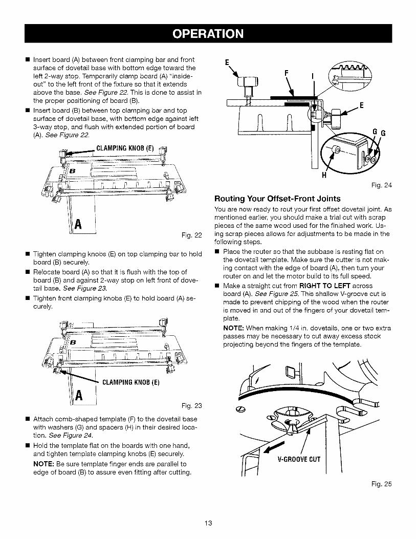
• Insertboard(A)betweenfrontclampingbarandfrontsurfaceof dovetailbasewithbottomedgetowardtheleft2-waystop.Temporarilyclampboard(A)"inside-out"to theleftfrontofthefixturesothatit extendsabovethebase.See Figure 22. This is done to assist inthe proper positioning of board (B).
• Insert board (B) between top clamping bar and topsurface of dovetail base, with bottom edge against left3-way stop, and flush with extended portion of board(A). See Figure 22.
CLAMPINGKNOB(E)
Fig. 22
• Tighten clamping knobs (E) on top clamping bar to holdboard (B) securely.
• Relocate board (A) so that it is flush with the top ofboard (B) and against 2-way stop on left front of dove-tail base. See Figure 23.
• Tighten front clamping knobs (E) to hold board (A) se-curely.
CLAMPINGKNOB(E)
H
Fig. 24
Routing Your Offset-Front Joints
You are now ready to rout your first offset dovetail joint. Asmentioned earlier, you should make a trial cut with scrappieces of the same wood used for the finished work. Us-ing scrap pieces allows for adjustments to be made in thefollowing steps.
• Place the router so that the subbase is resting flat onthe dovetail template. Make sure the cutter is not mak-ing contact with the edge of board (A), then turn yourrouter on and let the motor build to its full speed.
• Make a straight cut from RIGHT TO LEFT acrossboard (A). See Figure 25. This shallow V-groove cut ismade to prevent chipping of the wood when the routeris moved in and out of the fingers of your dovetail tem-plate.
NOTE: When making 1/4 in. dovetails, one or two extrapasses may be necessary to cut away excess stockprojecting beyond the fingers of the template.
Fig. 23
• Attach comb-shaped template (F) to the dovetail basewith washers (G) and spacers (H) in their desired loca-tion. See Figure 24.
• Hold the template flat on the boards with one hand,and tighten template clamping knobs (E) securely.
NOTE: Be sure template finger ends are parallel toedge of board (B) to assure even fitting after cutting.
GROOVECUT
Fig. 25
13
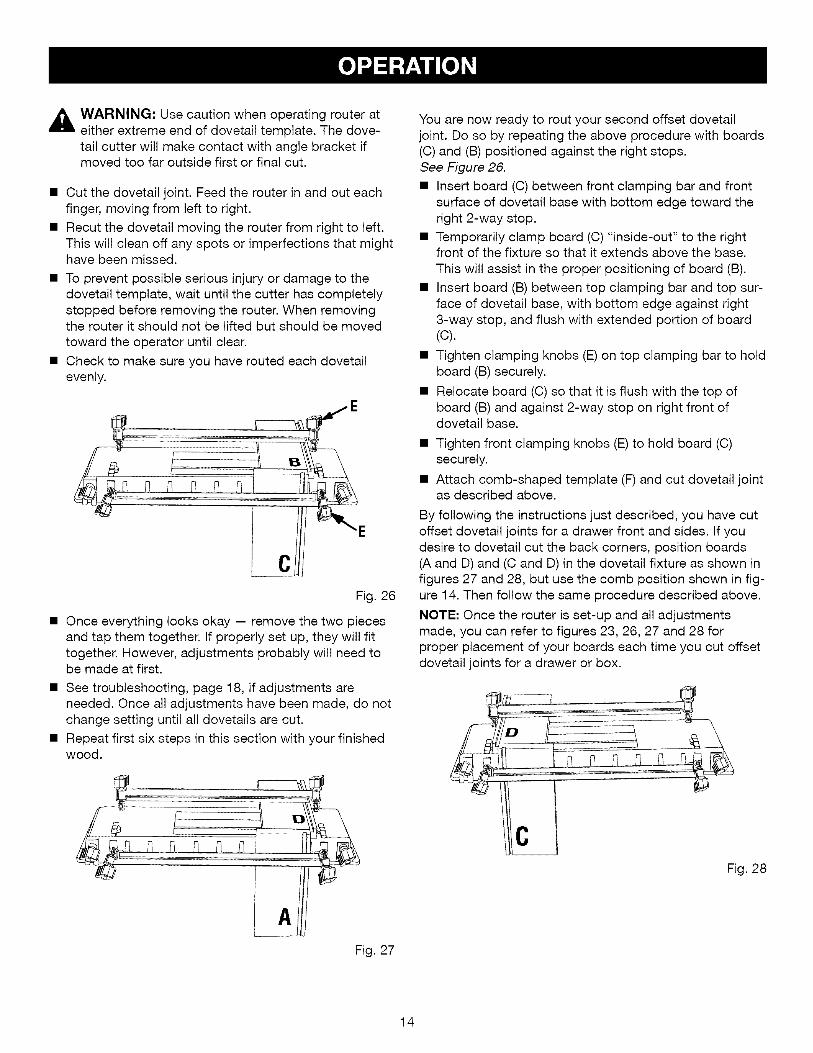
_ ARNING:Usecautionwhenoperatingrouterateitherextremeendofdovetailtemplate.Thedove-tailcutterwillmakecontactwithanglebracketifmovedtoofaroutsidefirstorfinalcut.
• Cutthedovetailjoint.Feedtherouterinandouteachfinger,movingfromleftto right.
• Recutthedovetailmovingtherouterfromrightto left.Thiswillcleanoff anyspotsor imperfectionsthatmighthavebeenmissed.
• Topreventpossibleseriousinjuryordamageto thedovetailtemplate,waituntilthecutterhascompletelystoppedbeforeremovingtherouter.Whenremovingtherouteritshouldnotbeliftedbutshouldbemovedtowardtheoperatoruntilclear.
• Checkto makesureyouhaveroutedeachdovetailevenly.
Fig.26
• Onceeverythinglooksokay-- removethetwopiecesandtapthemtogether.Ifproperlysetup,theywillfittogether.However,adjustmentsprobablywillneedtobemadeatfirst.
• Seetroubleshooting,page18,ifadjustmentsareneeded.Oncealladjustmentshavebeenmade,donotchangesettinguntilalldovetailsarecut.
• Repeatfirstsixstepsinthissectionwithyourfinishedwood.
Youarenowreadyto routyoursecondoffsetdovetailjoint.Dosobyrepeatingtheaboveprocedurewithboards(C)and(B)positionedagainsttherightstops.See Figure 26.
• Insert board (C) between front clamping bar and frontsurface of dovetail base with bottom edge toward theright 2-way stop.
• Temporarily clamp board (C) "inside-out" to the rightfront of the fixture so that it extends above the base.
This will assist in the proper positioning of board (B).
• Insert board (B) between top clamping bar and top sur-face of dovetail base, with bottom edge against right3-way stop, and flush with extended portion of board(C).
• Tighten clamping knobs (E) on top clamping bar to holdboard (B) securely.
• Relocate board (C) so that it is flush with the top ofboard (B) and against 2-way stop on right front ofdovetail base.
• Tighten front clamping knobs (E) to hold board (C)securely.
• Attach comb-shaped template (F) and cut dovetail jointas described above.
By following the instructions just described, you have cutoffset dovetail joints for a drawer front and sides. If youdesire to dovetail cut the back corners, position boards(A and D) and (C and D) in the dovetail fixture as shown infigures 27 and 28, but use the comb position shown in fig-ure 14. Then follow the same procedure described above.
NOTE: Once the router is set-up and all adjustmentsmade, you can refer to figures 23, 26, 27 and 28 forproper placement of your boards each time you cut offsetdovetail joints for a drawer or box.
Fig. 28
Fig. 27
14

RABBETED FRONT DRAWER
,_ WARNING: Unplug router from power supplywhile assembling parts or making adjustments.Failure to do so could result in accidental startingof the router causing damage to the work surfaceor possible serious personal injury.
A rabbeted front drawer is used when you want thedrawer front to overlap the top, bottom, and both sides ofthe drawer opening. The drawer front is both 3/4 in. widerthan the drawer sides and 3/4 in. longer than the drawerwidth. This will give you a 3/8 in. rabbet around yourdrawer front after you finish cutting your dovetail joints.
Set-up
• Cut a 3/8 in. wide x 7/16 in. deep rabbet around thedrawer front.
• Attach guide bushing to your router and install dovetailcutter. See "Installing template guide bushing and cut-ter", Page 7.
• Adjust the base on your router until the cutter extends17/32 in. below the router subbase for 1/2 in. joints.
17/32 in. FOR 7/16 in. FOR1/2 in. JOINTS 1/4 in. JOINTS
DOVETAILCUTTER
SUBBASE
Fig. 29
Adjust 7/16 in. below the router subbase for 1/4 in.joints. See Figure 29.
• Loosen the stop screws in your dovetail base andplace the 3-way stop on top and the 2-way stop on theside in their proper position. See Figures 8 and 30. Re-tighten stop screws securely.
3 WAYSTOP
STOP
Fig. 30
Mark the boards for the drawer or box on the inside
with identifying letters near the bottom edge.See Figure 31.NOTE: The reverse sides of the board will be the out-side of the finished drawer or box. The outside of the
boards are always clamped towards the dovetail baseand all pieces are routed in an "inside-out" position.The boards are then reversed to assemble.
NOTE: The front piece (B) should be 3/4 in. longer and3/4 in. wider than the back piece (D). The side pieces(A and C) should be the same size. See the chart onpage 9 for computing proper sizes and recommendedmaterial thicknesses.
SIDE(C)
if
RABBETEDFRONT(B)
Fig. 31
15
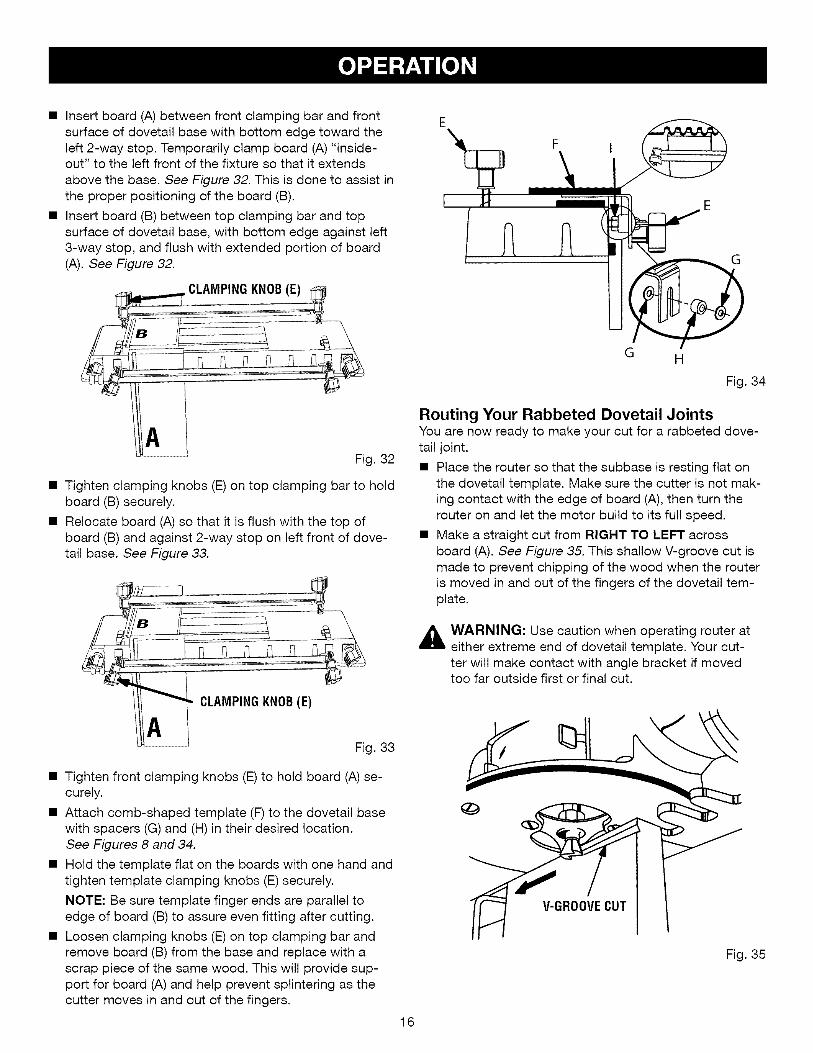
• Insertboard(A)betweenfrontclampingbarandfrontsurfaceof dovetailbasewithbottomedgetowardtheleft2-waystop.Temporarilyclampboard(A)"inside-out"to theleftfrontofthefixturesothatit extendsabovethebase.See Figure 32. This is done to assist inthe proper positioning of the board (B).
• Insert board (B) between top clamping bar and topsurface of dovetail base, with bottom edge against left3-way stop, and flush with extended portion of board(A). See Figure 32.
CLAMPINGKNOB(E)
G
Fig. 32
• Tighten clamping knobs (E) on top clamping bar to holdboard (B) securely.
• Relocate board (A) so that it is flush with the top ofboard (B) and against 2-way stop on left front of dove-tail base. See Figure 33.
CLAMPINGKNOB(E)
G H
Fig. 34
Routing Your Rabbeted Dovetail JointsYou are now ready to make your cut for a rabbeted dove-tail joint.
• Place the router so that the subbase is resting flat onthe dovetail template. Make sure the cutter is not mak-ing contact with the edge of board (A), then turn therouter on and let the motor build to its full speed.
• Make a straight cut from RIGHT TO LEFT acrossboard (A). See Figure 35. This shallow V-groove cut ismade to prevent chipping of the wood when the routeris moved in and out of the fingers of the dovetail tem-plate.
_ ARNING: Use caution when operating router ateither extreme end of dovetail template. Your cut-ter will make contact with angle bracket if movedtoo far outside first or final cut.
Fig. 33
• Tighten front clamping knobs (E) to hold board (A) se-curely.
• Attach comb-shaped template (F) to the dovetail basewith spacers (G) and (H) in their desired location.See Figures 8 and 34.
• Hold the template flat on the boards with one hand andtighten template clamping knobs (E) securely.
NOTE: Be sure template finger ends are parallel toedge of board (B) to assure even fitting after cutting.
• Loosen clamping knobs (E) on top clamping bar andremove board (B) from the base and replace with ascrap piece of the same wood. This will provide sup-port for board (A) and help prevent splintering as thecutter moves in and out of the fingers.
16
GROOVECUT
Fig. 35

• Cutyourdovetailjoint.Feedtherouterinandouteachfinger,movingfromleftto right.
• Recutthedovetailmovingtherouterfromrightto left.Thiswillcleanoffanyspotsor imperfectionsthatmighthavebeenmissed.
• Waituntilthecutterhascompletelystoppedbeforeremovingtherouter.Thiswillpreventpossibleseriousinjuryoranydamagetothedovetailtemplate.Whenremovingtherouter,it shouldnotbeliftedbutshouldbemovedtowardtheoperatoruntilclear.
• Checkto makesureyouhaveroutedeachdovetailevenly.
• Loosentemplateclampingknobs(E)andremovecomb-shapedtemplate(F).donotremoveboard(A).
• Loosenclampingknobs(E)ontopclampingbarandremovescrappieceof wood.
• Replacethescrappieceofwoodwiththepiecethatisto beyourfinishedfrontboard(B).
• Placeitflushwiththeedgeof board(A),andtightenclampingknobs(E)ontopclampingbarfirmly.
• Loosenclampingknobs(E)onfrontclampingbarandremoveboard(A).
• Attachcomb-shapedtemplate(F)to thedovetailbasewithspacers(G)and(H)intheirdesiredlocation.See Figure 36. Hold the template flat on the boardswith one hand and tighten clamping knobs (E) securely.
H
G
• See Figure 37. With the dovetail template set-up asshown, cut your joint in board (B) as a single piece.
• Recut the dovetail moving from right to left to cleanoff any spots or imperfections that might have beenmissed.
Fig. 37
To rout the other side of your rabbeted front drawer,repeat the above procedure with boards (C) and (B)positioned against the right stops. See Figure 38. To routdovetail cuts in board (D) and boards (A and C) follow theinstructions for making a "flush front drawer or box" onpages 10 and 11.
BOARD(B)
Fig. 36
Fig. 38
17

HELPFUL HINTS
• Once all adjustments are made, do not make any fur-ther changes until all dovetails are cut.
• Always clamp workpiece securely for cutting.
• Rout dovetails from the front only.
• A safe operator is one who thinks ahead.
• Do not raise or lower your router or cutter while the bitis between the dovetail template fingers.
• Keep router base flat against template.
• Always wear eye protection when routing.
• Make certain the ends of all boards are square.
• Make set-up adjustments carefully. Then double check.Measure twice and cut once.
• DO NOT use warped boards.
• Keep cutters clean and properly sharpened.
• Be consistent when selecting the thickness of yourboards.
• Don't let familiarity make you careless.
• Always bevel the drawer front for an offset-frontdrawer.
• Study all safety rules and do the job safely.
• Plan your drawer height opening so that the boards willbe in increments of 7/8 in. for 1/2 in. joints, or 29/64 in.increments for 1/4 in. joints. This will allow a half-pinto be on both the top and bottom edge of the drawerfront. Don't forget to allow for clearances.
• NEVER place your hands in jeopardy.
• Make certain clamps can't loosen while in use.
• Test difficult set-ups on scrap -- Don't waste lumber.
• Plan each operation before you begin.• THINK SAFETY BY THINKING AHEAD,
PROBLEM SOLUTION
If the joint is too tight Raise the cutter very slightly. This will make the cut moreshallow (approximately 1/64 in.). See depth adjustmentinstructions as explained in the router operator's manual.
If the joint is too loose Lower the cutter bit very slightly to make the cut deeper(approximately 1/64 in.).
If the fit is too deep _ Turn the lock nut (I) in a counter-clockwise direction untildesired depth is reached. See Figures 14, 17, or 18.NOTE: Be sure to adjust both lock nuts equally.
]]
__Fig. 39
If the fit is too shallow
Fig. 40
Turn the lock nut (I) in a clockwise direction until the de-sired depth is reached. NOTE: Be sure to adjust both locknuts equally.
18

[CRAFTSMAN PRODUCT NAME - MODEL NUMBER 315.25791
The model number will be found on a plate attached to the motor housing. Always mention the modelnumber in all correspondence regarding your accessory or when ordering repair parts.
SEE BACK PAGE FOR PARTS ORDERING INSTRUCTIONS
]
I" 2 I"_ ,_3
I9
/
162
t
f
17
I19 3
62
1
* Standard Hardware Item - May Be Purchased Locally** Available From Div. 98 - Source 980.0
*** Complete assortment available at your Nearest Sears Retail Store
19

ICRAFTSMAN PRODUCT NAME - MODEL NUMBER 315.25791
The model number will be found on a label attached to the base. Always mention the model number inall correspondence regarding your accessory or when ordering repair parts.
SEE BACK PAGE FOR PARTS ORDERING INSTRUCTIONS
]
Key PartNo. Number
1 000900067001
2 000900067002
3 000900067003
4 000900067004
5 000900067005
6 000900067006
7 000900067007
8 000900067008
9 000900067009
10 000900067010
11 000900067011
12 000900067012
13 000900067013
14 000900067014
15 000900067015
16 000900067016
17 000900067017
18 000900067018
19 000900067021
20 000900067019
21 000900067020
22
983000533
PARTS LIST
Description Qty.
Clamping Knob ............................................................................................... 6
Washer .......................................................................................................... 12
Clamp Bar ....................................................................................................... 2
Spring .............................................................................................................. 4
Nut (1/4-20) ..................................................................................................... 6
* Screw (#10-32 x 1/2 in. Flat Head Thread Cutting) ......................................... 2
Template .......................................................................................................... 1
Angle Bracket .................................................................................................. 2
Label ................................................................................................................ 1
Hex Bolt (1/4-20 x 3 in.) .................................................................................. 4
* Screw (#8-32 x 7/8 in. Flat Head) .................................................................... 4
3 Way Stop ...................................................................................................... 2
Base ................................................................................................................ 1
Hex Bolt (#1/4-20 x 1-3/4 in.) .......................................................................... 2
Lock Nut (#1/4-20) .......................................................................................... 2
Spacer ............................................................................................................. 2
2 Way Stop ...................................................................................................... 2
Square Nut (#8-32) **STD541008 ................................................................... 4
* Screw (#10-32 x 7/8 in. Flat Head) .................................................................. 3
7/16 in. Guide Bushing .................................................................................... 1
5/16 in. Guide Bushing .................................................................................... 1
Data Label (Not Shown) .................................................................................. 1
Operator's Manual
* Standard Hardware Item - May Be Purchased Locally
** Available From Div. 98 - Source 980.0
*** Complete assortment available at your Nearest Sears Retail Store
2O