Operators Manual For The Model 6640T Series Automatic DCC ...
47
Operators Manual For The Model 6640T Series Automatic DCC Thermometry Bridge www.guildline.com NOTICE The contents and information contained in this manual are proprietary to Guildline Instruments Limited. They are to be used only as a guide to the operation and maintenance of the equipment with which this manual was issued and may not be duplicated or transmitted by any means, either in whole or in part, without the written permission of Guildline Instruments Limited. OM6640T-4-00 01 December, 2017
Transcript of Operators Manual For The Model 6640T Series Automatic DCC ...

Operators Manual
For The
Model 6640T Series
Automatic DCC Thermometry Bridge
www.guildline.com
NOTICE
The contents and information contained in this manual are proprietary to
Guildline Instruments Limited. They are to be used only as a guide to the
operation and maintenance of the equipment with which this manual was
issued and may not be duplicated or transmitted by any means, either in whole
or in part, without the written permission of Guildline Instruments Limited.
OM6640T-4-00
01 December, 2017

OM6640T-4-00
01 December, 2017 i
TABLE OF CONTENTS
1. INTRODUCTION ....................................................................................................... 1-1
1.1. SCOPE ................................................................................................................................................................ 1-1
1.2. GENERAL DESCRIPTION ............................................................................................................................ 1-1
1.3. OVERVIEW ...................................................................................................................................................... 1-2
1.4. PRINCIPLE OF OPERATION ....................................................................................................................... 1-3 1.4.1.1. Normal Ohm Measurement Mode ........................................................................................................ 1-4
2. PERFORMANCE SPECIFICATIONS ....................................................................... 2-1
2.1. 6640T SERIES TEMPERATURE MEASUREMENT SPECIFICATION ............................................... 2-1
3. OPERATING INSTRUCTIONS ................................................................................. 3-1
3.1. FRONT PANEL OPERATING PROCEDURE ............................................................................................ 3-1 3.2.1. Exit .................................................................................................................................................................. 3-3 3.2.2. Enable Remote ................................................................................................................................................ 3-4 3.2.3. Start Measurement .......................................................................................................................................... 3-4 3.2.4. Measurement Setup ........................................................................................................................................ 3-4 3.2.5. Log Data ......................................................................................................................................................... 3-4 3.2.6. Setup ............................................................................................................................................................... 3-4 3.4.1. Quick ............................................................................................................................................................... 3-5 3.4.2. Power .............................................................................................................................................................. 3-6 3.4.3. Ohms Mode .................................................................................................................................................... 3-6 3.4.4. Reference Resistor .......................................................................................................................................... 3-6 3.4.5. RX Approximation ......................................................................................................................................... 3-6 3.4.6. Reversal Rate .................................................................................................................................................. 3-6 3.4.7. Sample Rate .................................................................................................................................................... 3-6 3.4.8. Serial Number ................................................................................................................................................. 3-7 3.4.9. Test Current .................................................................................................................................................... 3-7 3.4.10. Maximum Current ..................................................................................................................................... 3-7 3.4.11. Resistance .................................................................................................................................................. 3-7 3.4.12. Cancel ........................................................................................................................................................ 3-7 3.4.13. Apply ......................................................................................................................................................... 3-7 3.5.1. Standard .......................................................................................................................................................... 3-8 3.5.2. Quick ............................................................................................................................................................... 3-8 3.5.3. Power .............................................................................................................................................................. 3-8 3.5.4. Ohms Mode .................................................................................................................................................... 3-9 3.5.5. Reference Resistor .......................................................................................................................................... 3-9 3.5.6. Probe RTPW................................................................................................................................................... 3-9 3.5.7. Reversal Rate .................................................................................................................................................. 3-9 3.5.8. Sample Rate .................................................................................................................................................... 3-9 3.5.9. Serial Number ................................................................................................................................................. 3-9 3.5.10. Serial Number .......................................................................................................................................... 3-10 3.5.11. Test Current ............................................................................................................................................. 3-10 3.5.12. Maximum Current ................................................................................................................................... 3-10 3.5.13. Temperature ............................................................................................................................................. 3-10 3.5.14. -Coefficients ............................................................................................................................................. 3-10

OM6640T-4-00
01 December, 2017 ii
3.5.15. +Coefficients ............................................................................................................................................ 3-10 3.5.16. Coefficients .............................................................................................................................................. 3-10 3.5.17. Cancel ...................................................................................................................................................... 3-10 3.5.18. Apply ....................................................................................................................................................... 3-11 3.6.1. Quick ............................................................................................................................................................. 3-11 3.6.2. Power ............................................................................................................................................................ 3-11 3.6.3. A, B, and C Coefficients ............................................................................................................................... 3-11 3.6.4. Range ............................................................................................................................................................ 3-12 3.6.5. Cancel ........................................................................................................................................................... 3-12 3.6.6. Apply ............................................................................................................................................................ 3-12 3.7.1. Quick ............................................................................................................................................................. 3-12 3.7.2. Power ............................................................................................................................................................ 3-12 3.7.3. A, B, C, and D Coefficients .......................................................................................................................... 3-13 3.7.4. Range ............................................................................................................................................................ 3-13 3.7.5. Cancel ........................................................................................................................................................... 3-13 3.7.6. Apply ............................................................................................................................................................ 3-13 3.8.1. Temperature Unit .......................................................................................................................................... 3-13 3.8.2. Data Logging Interval ................................................................................................................................... 3-13 3.8.3. Detailed Graph Length ................................................................................................................................. 3-14 3.8.4. Cancel ........................................................................................................................................................... 3-14 3.8.5. Apply ............................................................................................................................................................ 3-14 3.9.1. Incoming Interface ........................................................................................................................................ 3-14 3.9.2. Connection Timeout ..................................................................................................................................... 3-15 3.9.3. Outgoing Interface ........................................................................................................................................ 3-15 3.9.4. Serial Port/GPIB Address/ IP Address ......................................................................................................... 3-15 3.9.5. Communication Timeout .............................................................................................................................. 3-15 3.9.6. Cancel ........................................................................................................................................................... 3-15 3.9.7. Apply ............................................................................................................................................................ 3-15
3.10. MEASUREMENT OPERATION GUIDE ................................................................................................... 3-16
3.11. BRIDGEWORKS-ADV DATA ACQUISITION SOFTWARE ................................................................ 3-16
4. MAINTENANCE ........................................................................................................ 4-1
4.1. INTRODUCTION ............................................................................................................................................. 4-1
4.2. TEMPERATURE RATIO VERIFICATION ................................................................................................ 4-1 4.2.1. PURPOSE ....................................................................................................................................................... 4-1 4.2.2. EQUIPMENT REQUIRED ........................................................................................................................... 4-1
4.3. MODEL 6640T BRIDGE VERIFICATION .................................................................................................. 4-2 4.3.1. Set Up ............................................................................................................................................................. 4-2 4.3.2. Inputs-Outputs Verification ............................................................................................................................ 4-2
5. REMOTE CONTROL ................................................................................................ 5-1
MODEL 6640 PROGRAMMING COMMAND SUMMARY ................................................................................... 5-1

OM6640T-4-00
01 December, 2017 iii
LIST OF FIGURES FIGURE 1-1 : MODEL 6640T BLOCK DIAGRAM .................................................................................................. 1-4 FIGURE 3-1 : USER INTERFACE NAVIGATION DIAGRAM .............................................................................. 3-2

OM6640T-4-00
01 December, 2017 iv
LIST OF TABLES TABLE 3-1 : RECOMMENDED TEMPERATURE MEASUREMENT TEST SETUP ..................................... 3-16

Section 1
OM6640T-4-00
01 December, 2017
1-1
1. INTRODUCTION
1.1. SCOPE
This document describes the operation and maintenance of the 6640T Series of Automatic DCC
Resistance Bridges.
1.2. GENERAL DESCRIPTION
The 6640T series bridges can be controlled from the front panel or by a computer system through
software. The BridgeWorks Software User’s Manual describes the operation of the 6640T with the
software. Once the computer system is installed and connected to the IEEE-488 Interface of the
6640T Resistance Bridge, full software control of the bridge is possible. The following models are
described in this manual.
6640T-B (Base model with measurement up to 100 kΩ)
6640T-XP (eXtended Precision model with measurement up to 100 kΩ, and higher accuracy)

Section 1
OM6640T-4-00
01 December, 2017
1-2
1.3. OVERVIEW
The 6640T is a microprocessor-based, direct-current-comparator bridge designed for the automatic
measurement and display of the ratio of two resistances to accuracies better than 0.1 ppm. The ratio
of the two resistances is determined from a direct measurement of the voltage of the bridge
imbalance while an ampere-turn balance is maintained. A microprocessor is used to control the
direct-current-comparator, set the bridge measurement currents and measurement configuration,
initiate the voltage measurement cycle and maintain the ampere-turn balance. This fully automated
measurement process achieves optimum resistance ratio resolution and accuracy at the sub-ppm
level.
The bridge is designed for flexibility and ease of use and is based on the direct-current-comparator
bridge (DCC)originally developed by the National Research Council of Canada. Guildline first
commercialized DCC Temperature Bridges (i.e. model 9975), and subsequently made major
enhancements with the Guildline 6675(A) and 6622T automated temperature bridges.1. The 6640T
contains additional improvements, which are protected by two patents, and provides the best
commercially available temperature brodge. Remote access to the embedded microprocessor-
controller, through a simple control language command set and GPIB communication interface
allows the 6640T to fully exploit the capabilities of the direct-current-comparator to suit each user
requirement while still maintaining optimum resistance ratio measurement accuracy at the sub-ppm
level.
The design approach taken for the 6640T results in an effective bridge measurement accuracy of 27
bits (to a maximum of 32 bits depending on configuration), allowing the resistance ratio of
resistances in the range 0.001 to 100 k to be automatically measured. Options are available to
extend the measurement range to 1 G
The balance of the zero ampere-turn flux condition is maintained automatically using an electronic
closed loop feedback network operating on the flux detector output to drive a slave power supply
for the standard resistor current. The bridge balance (null voltage condition) is maintained
automatically by adjusting the number of turns in series with the unknown resistor.
1 MacMartin, M.P. and Kusters, N.L., "A direct -current-comparator for four terminal
resistance measurements", IEEE Trans. Instrumentation and Measurement, vol IM-15,
pp.212-220, December 1966.
Section 1
OM6640T-4-00
01 December, 2017
1-3
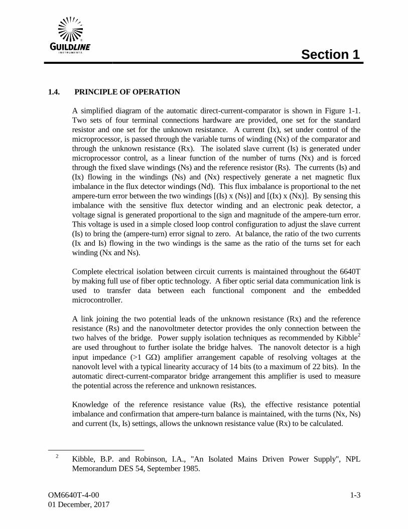
1.4. PRINCIPLE OF OPERATION
A simplified diagram of the automatic direct-current-comparator is shown in Figure 1-1.
Two sets of four terminal connections hardware are provided, one set for the standard
resistor and one set for the unknown resistance. A current (Ix), set under control of the
microprocessor, is passed through the variable turns of winding (Nx) of the comparator and
through the unknown resistance (Rx). The isolated slave current (Is) is generated under
microprocessor control, as a linear function of the number of turns (Nx) and is forced
through the fixed slave windings (Ns) and the reference resistor (Rs). The currents (Is) and
(Ix) flowing in the windings (Ns) and (Nx) respectively generate a net magnetic flux
imbalance in the flux detector windings (Nd). This flux imbalance is proportional to the net
ampere-turn error between the two windings [(Is) x (Ns)] and [(Ix) x (Nx)]. By sensing this
imbalance with the sensitive flux detector winding and an electronic peak detector, a
voltage signal is generated proportional to the sign and magnitude of the ampere-turn error.
This voltage is used in a simple closed loop control configuration to adjust the slave current
(Is) to bring the (ampere-turn) error signal to zero. At balance, the ratio of the two currents
(Ix and Is) flowing in the two windings is the same as the ratio of the turns set for each
winding (Nx and Ns).
Complete electrical isolation between circuit currents is maintained throughout the 6640T
by making full use of fiber optic technology. A fiber optic serial data communication link is
used to transfer data between each functional component and the embedded
microcontroller.
A link joining the two potential leads of the unknown resistance (Rx) and the reference
resistance (Rs) and the nanovoltmeter detector provides the only connection between the
two halves of the bridge. Power supply isolation techniques as recommended by Kibble2
are used throughout to further isolate the bridge halves. The nanovolt detector is a high
input impedance (>1 G) amplifier arrangement capable of resolving voltages at the
nanovolt level with a typical linearity accuracy of 14 bits (to a maximum of 22 bits). In the
automatic direct-current-comparator bridge arrangement this amplifier is used to measure
the potential across the reference and unknown resistances.
Knowledge of the reference resistance value (Rs), the effective resistance potential
imbalance and confirmation that ampere-turn balance is maintained, with the turns (Nx, Ns)
and current (Ix, Is) settings, allows the unknown resistance value (Rx) to be calculated.
2 Kibble, B.P. and Robinson, I.A., "An Isolated Mains Driven Power Supply", NPL
Memorandum DES 54, September 1985.
Section 1
OM6640T-4-00
01 December, 2017
1-4
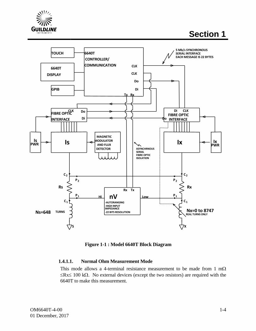
Figure 1-1 : Model 6640T Block Diagram
1.4.1.1. Normal Ohm Measurement Mode
This mode allows a 4-terminal resistance measurement to be made from 1 m
Rx 100 k. No external devices (except the two resistors) are required with the
6640T to make this measurement.
DETECTOR
AND FLUX
MODULATOR
MAGNETIC
X
6640T
DISPLAY
TOUCH
GPIB
6640T
CONTROLLER/
COMMUNICATION CLK CLK
Do Di
FIBRE OPTIC
INTERFACE
Do Di Do
Di
C 1 1 P
Is Is PWR Ix
FIBRE OPTIC INTERFACE
Ix PWR
Nx=0 to 8747 REAL TURNS ONLY
2 C P 2
Rx Tx
Rx Tx Rx
C 2 P 2
P 1 C 1
S
Rs
Ns=648 TURNS -AUTORANGING -HIGH INPUT
IMPEDANCE -22 BITS RESOLUTION
Hi nV
ASYNCHRNOUS SERIAL FIBRE OPTIC ISOLATION
5 Mb/s SYNCHRONOUS SERIAL INTERFACE EACH MESSAGE IS 22 BYTES
Low
CLK CLK

Section 2
OM6640T-4-00
01 December, 2017
2-1
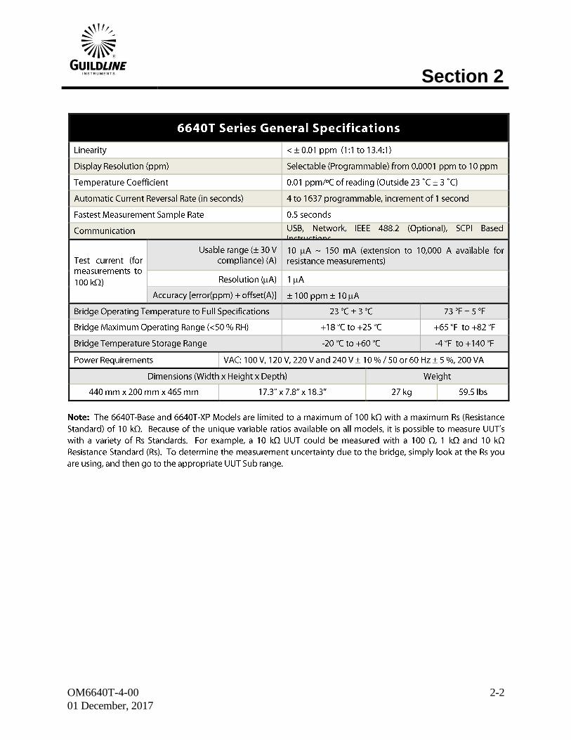
2. PERFORMANCE SPECIFICATIONS
2.1. 6640T SERIES TEMPERATURE MEASUREMENT SPECIFICATION
Section 2
OM6640T-4-00
01 December, 2017
2-2
Section 3
OM6640T-4-00
01 December, 2017
3-1
3. OPERATING INSTRUCTIONS
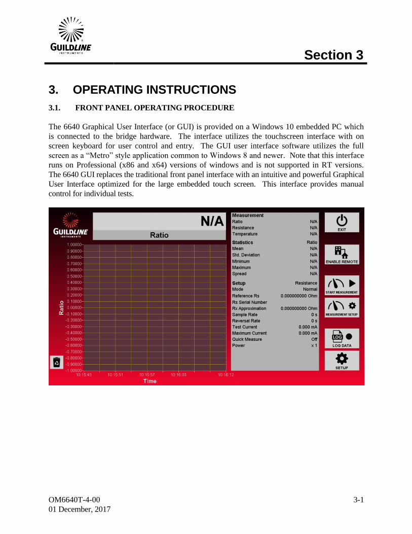
3.1. FRONT PANEL OPERATING PROCEDURE
The 6640 Graphical User Interface (or GUI) is provided on a Windows 10 embedded PC which
is connected to the bridge hardware. The interface utilizes the touchscreen interface with on
screen keyboard for user control and entry. The GUI user interface software utilizes the full
screen as a “Metro” style application common to Windows 8 and newer. Note that this interface
runs on Professional (x86 and x64) versions of windows and is not supported in RT versions.
The 6640 GUI replaces the traditional front panel interface with an intuitive and powerful Graphical
User Interface optimized for the large embedded touch screen. This interface provides manual
control for individual tests.
Section 3
OM6640T-4-00
01 December, 2017
3-2
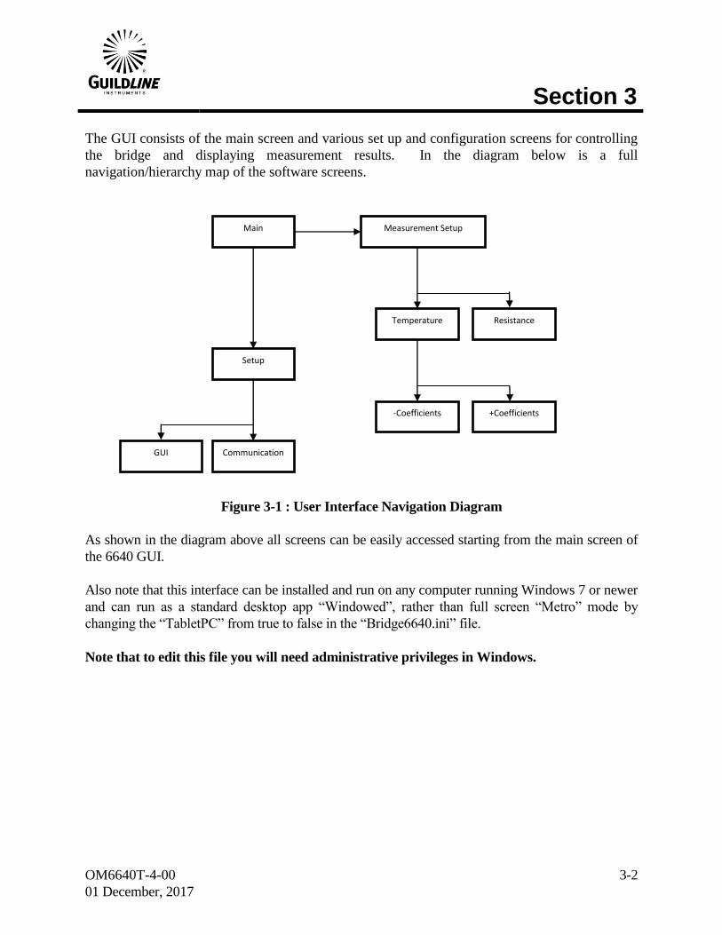
The GUI consists of the main screen and various set up and configuration screens for controlling
the bridge and displaying measurement results. In the diagram below is a full
navigation/hierarchy map of the software screens.
Figure 3-1 : User Interface Navigation Diagram
As shown in the diagram above all screens can be easily accessed starting from the main screen of
the 6640 GUI.
Also note that this interface can be installed and run on any computer running Windows 7 or newer
and can run as a standard desktop app “Windowed”, rather than full screen “Metro” mode by
changing the “TabletPC” from true to false in the “Bridge6640.ini” file.
Note that to edit this file you will need administrative privileges in Windows.
Main Measurement Setup
Setup
GUI Communication
Temperature Resistance
-Coefficients +Coefficients
Section 3
OM6640T-4-00
01 December, 2017
3-3
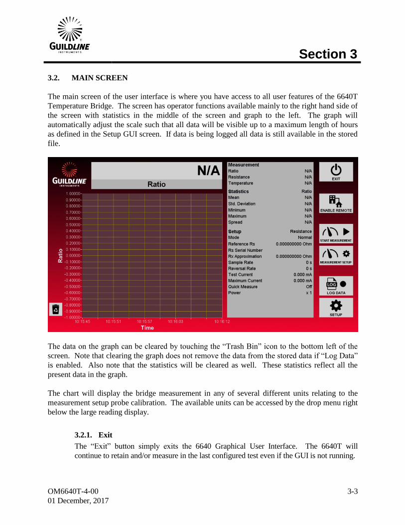
3.2. MAIN SCREEN
The main screen of the user interface is where you have access to all user features of the 6640T
Temperature Bridge. The screen has operator functions available mainly to the right hand side of
the screen with statistics in the middle of the screen and graph to the left. The graph will
automatically adjust the scale such that all data will be visible up to a maximum length of hours
as defined in the Setup GUI screen. If data is being logged all data is still available in the stored
file.
The data on the graph can be cleared by touching the “Trash Bin” icon to the bottom left of the
screen. Note that clearing the graph does not remove the data from the stored data if “Log Data”
is enabled. Also note that the statistics will be cleared as well. These statistics reflect all the
present data in the graph.
The chart will display the bridge measurement in any of several different units relating to the
measurement setup probe calibration. The available units can be accessed by the drop menu right
below the large reading display.
3.2.1. Exit
The “Exit” button simply exits the 6640 Graphical User Interface. The 6640T will
continue to retain and/or measure in the last configured test even if the GUI is not running.
Section 3
OM6640T-4-00
01 December, 2017
3-4
3.2.2. Enable Remote
The “Enable Remote” button disables all interactive features of the GUI and allows the
6640T Bridge to be controlled by another computer via RS-232C, GPIB, or over the
network with TCP/IP. Any one of these options can be used at any time. While remote is
enabled the GUI will still display the graph, statistics and measurement reading.
3.2.3. Start Measurement
The “Start Measurement” button toggles between “Start Measurement” and “Stop
Measurement”. This button will place the 6640T hardware into measurement running and
standby conditions.
3.2.4. Measurement Setup
The “Measurement Setup” button opens a screen for setting up and changing the test
parameters of the test.
3.2.5. Log Data
The “Log Data” button will begin to store the bath temperature data to a standard comma
separated values format file. This file is stored in “C:\Results\YYYY\YYYY-MM\
Bridge6640_DataLog_YYYYMMDD_0001.csv”. This path and name is generated
automatically where “YYYY” is the year, “MM” is the month, and “DD” is the day. To
keep file sizes reasonable and to ensure there are no filename conflicts the name is also
given a 4 digit incremental number as well. The “Log Data” button will change to a “Stop
Logging” button when there is an active logging operation.
3.2.6. Setup
The “Setup” button opens the screens used to configure the system parameters of the
6640T GUI.

Section 3
OM6640T-4-00
01 December, 2017
3-5
3.3. SETUP MEASUREMENT SCREENS
The Setup Measurement Screens are screens to configure the test setup for the 6640T. There are
2 operational modes. Pressing the “Measurement Setup” button on the main screen will open the
last used mode setup screen. The two modes are “Resistance” and “Thermometry”. Resistance
is used for measuring stable resistance ratios that are typically used for fixed point thermometry
and/or two physical resistors. This mode is ideal for SPRT calibrations and the available units
for this mode of operation are limited to Ratio and Resistance. The Thermometry mode is best
for when you wish to display temperature readout on unknown and moving temperatures,
essentially making the bridge operate as a thermometer. Provided on the right of the screen are
buttons to toggle the measurement mode from “Resistance” to “Temperature” and navigate to the
other relevant Setup Measurement screens.
3.4. SETUP MEASUREMENT SCREEN (RESISTANCE)
The Setup Measurement Screen for resistance mode is a simpler screen for setting up the test as
there are no temperature conversion coefficients to enter. To use this screen simply type in the
desired test parameters as defined below and press “Apply” to accept. Click on “Cancel” to close
the window without changing the values.
The Setup Measurement Screen can easily be accessed directly on the Main Screen by touching the
“SETUP MEASUREMENT” button on the right hand side of the screen.
3.4.1. Quick
The “Quick” measure function disables the internal software filters that are invoked for the
four cycle precision measurements and are used in the calculation of resistance ratio.
Disabling the software filter function decreases the time required to calculate and report the
measured ratio. However, the measurement will be noisier when the quick measure is
used, and so two least significant digits of available resolution are removed from the
display when quick measure is turned on.
Section 3
OM6640T-4-00
01 December, 2017
3-6
3.4.2. Power
The “Power” function is where you can quickly double or reduce to half the excitation
current in your probe. This is used to help determine the self-heating effects of the probe
in use.
3.4.3. Ohms Mode
The “Ohms Mode” control allows you to set up to use a range extender for “Low Ohms”
current measurements, or voltage for “High Ohms” measurements, as well as the default,
which is current for “Normal” measurements. At this time the only applicable resistance
mode in a thermometry bridge is “Normal” which is used for low current sourced
measurements. Do not use the other modes as they are there for future expansion for wide
range temperature/resistance bridges.
3.4.4. Reference Resistor
The “Reference Resistor” field is where you can type in the actual value for the known
reference resistor you are using. This field is mandatory as it is used to index the
appropriate ratio calibration software coefficients retained inside the 6640T hardware.
3.4.5. RX Approximation
The “RX Approximation” field is where you can type in the approximate value for the
unknown resistor you are measuring. This field is not required as the bridge will auto
balance to find this value. Entering an approximate value does speed up the balancing
process.
3.4.6. Reversal Rate
The “Reversal Rate” sets the time (in seconds) in which the excitation current polarity is
reversed to remove induced errors created by thermal offsets. In most cases the
recommended setting for this is 20 seconds in thermometry applications. This value can be
set from 4 to 7200. This field is mandatory.
3.4.7. Sample Rate
The “Sample Rate” sets the time (in seconds) in which the bridge reports a reading. This
reading rate can be desynchronized from the current polarity reversal to any value entered
into this field. If this field is set to zero then the sample rate is synchronized to the reversal
rate and will report two times in each polarity. In most cases this is the recommended
setting. Values entered in this field must be less than the reversal rate and not smaller than
2 seconds. It is not mandatory, but recommended that any values entered should be a
factor of the reversal rate.
Section 3
OM6640T-4-00
01 December, 2017
3-7
3.4.8. Serial Number
The “Serial Number” field is where you can type in the serial number for the known
reference resistor you are using. This field is not mandatory.
3.4.9. Test Current
The “Test Current” field is where you can type in the excitation current for the probe or
resistor you are measuring. Typically this will be 1mA or 10mA for SPRT’s and HTPRT’s
respectively. This field is mandatory.
3.4.10. Maximum Current
The “Maximum Current” field is where you can type in the maximum current for the
reference resistor you are using. If the bridge detects that the resistor will be excited
beyond this value, then the test is automatically stopped. This field is mandatory and the
maximum value is 150 mA.
3.4.11. Resistance
The “Resistance” button is a toggle button to switch from “Resistance” mode to
“Temperature” mode. This button will change to indicate the currently active mode.
3.4.12. Cancel
The “Cancel” button will close the Setup Measurement screen without applying any
changes.
3.4.13. Apply
The “Apply” button will implement the new Setup Measurement as displayed on the
screen.

Section 3
OM6640T-4-00
01 December, 2017
3-8
3.5. SETUP MEASUREMENT SCREEN (TEMPERATURE)
The Setup Measurement Screen for temperature mode is a more complex screen for setting up
the test as there are temperature conversion coefficients to enter. To use this screen simply type
in the desired test parameters as defined below and press “Apply” to accept. Click on “Cancel”
to close the window without changing the values.
The Setup Measurement Screen can easily be accessed directly on the Main Screen by touching the
“SETUP MEASUREMENT” button on the right hand side of the screen.
3.5.1. Standard
The “Standard” function is used to select the temperature conversion standard that is being
used to translate a calibrated SPRT’s resistance to temperature reading. The available
standards for this are ITS-90 and IPTS-68. The “Coefficients” button options to the right
of the screen and subsequent screens will change to reflect the scale in use.
3.5.2. Quick
The “Quick” measure function disables the internal software filters that are invoked for the
four cycle precision measurements and are used in the calculation of resistance ratio.
Disabling the software filter function decreases the time required to calculate and report the
measured ratio. However, the measurement will be noisier, and so two least significant
digits of available resolution are removed from the display when quick measure is turned
on.
3.5.3. Power
The “Power” function is where you can quickly double or reduce to half the excitation
current in your probe. This is used to help determine the self-heating effects of the probe
in use.
Section 3
OM6640T-4-00
01 December, 2017
3-9
3.5.4. Ohms Mode
The “Ohms Mode” control allows you to set up to use a range extender for “Low Ohms”
current measurements, or voltage for “High Ohms” measurements, as well as the default,
which is current for “Normal” measurements. Currently the only applicable resistance
mode in a thermometry bridge is “Normal” which is used for low current sourced
measurements. Do not use the other modes as they are there for future expansion for wide
range temperature/resistance bridges.
3.5.5. Reference Resistor
The “Reference Resistor” field is where you can type in the actual value for the known
reference resistor you are using. This field is mandatory as it is used to index the
appropriate ratio calibration software coefficients retained inside the 6640T hardware.
3.5.6. Probe RTPW
The “Probe RTPW” field is where you can type in the known value for the triple point
resistance of the probe you are measuring. This field is not required for the bridge to
balance and measure. Entering a value for this parameter is required for accurate
conversion from resistance to temperature.
3.5.7. Reversal Rate
The “Reversal Rate” sets the time (in seconds) in which the excitation current polarity is
reversed to remove induced errors created by thermal offsets. In most cases the
recommended setting for this is 20 seconds in thermometry applications. This value can be
set from 4 to 7200. This field is mandatory.
3.5.8. Sample Rate
The “Sample Rate” sets the time (in seconds) in which the bridge reports a reading. This
reading rate can be desynchronized from the current polarity reversal to any value entered
into this field. If this field is set to zero then the sample rate is synchronized to the reversal
rate and will report two times in each polarity. In most cases this is the recommended
setting for this parameter. Values entered in this field must be less than the reversal rate
and not smaller than 2 seconds. It is not mandatory, but recommended that any values
entered should be a factor of the reversal rate.
3.5.9. Serial Number
The “Serial Number” field is where you can type in the serial number for the known
reference resistor you are using. This field is not mandatory.
Section 3
OM6640T-4-00
01 December, 2017
3-10
3.5.10. Serial Number
The “Serial Number” field is where you can type in the serial number for the
SPRT/HTPRT you are using. This field is not mandatory.
3.5.11. Test Current
The “Test Current” field is where you can type in the excitation current for the probe or
resistor you are measuring. Typically this will be 1mA or 10mA for SPRT’s and HTPRT’s
respectively. This field is mandatory.
3.5.12. Maximum Current
The “Maximum Current” field is where you can type in the maximum current for the
reference resistor you are using. If the bridge detects that the resistor will be excited
beyond this value, then the test is automatically stopped. This field is mandatory and has a
maximum value of 150 mA.
3.5.13. Temperature
The “Temperature” button is a toggle button to switch from “Resistance” mode to
“Temperature” mode. This button will change to indicate the currently active mode.
3.5.14. -Coefficients
The “-Coefficients” button appears in “Temperature” mode along with the “+Coefficients”
button when using the ITS-90 Standard. Selecting this button opens a screen to select the
desired sub-range and to enter coefficients for the chosen sub-range.
3.5.15. +Coefficients
The “+Coefficients” button appears in “Temperature” mode along with the “-Coefficients”
button when using the ITS-90 Standard. Selecting this button opens a screen to select the
desired sub-range and to enter coefficients for the chosen sub-range.
3.5.16. Coefficients
The “Coefficients” (unsigned) button appears in “Temperature” mode as a single button
when using the IPTS-68 Standard. Selecting this button opens a screen to enter
coefficients.
3.5.17. Cancel
The “Cancel” button will close the Setup Measurement screen without applying any
changes.
Section 3
OM6640T-4-00
01 December, 2017
3-11
3.5.18. Apply
The “Apply” button will implement the new Setup Measurement as displayed on the
screen.
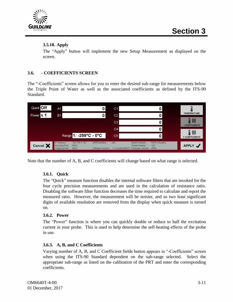
3.6. - COEFFICIENTS SCREEN
The “-Coefficients” screen allows for you to enter the desired sub-range for measurements below
the Triple Point of Water as well as the associated coefficients as defined by the ITS-90
Standard.
Note that the number of A, B, and C coefficients will change based on what range is selected.
3.6.1. Quick
The “Quick” measure function disables the internal software filters that are invoked for the
four cycle precision measurements and are used in the calculation of resistance ratio.
Disabling the software filter function decreases the time required to calculate and report the
measured ratio. However, the measurement will be noisier, and so two least significant
digits of available resolution are removed from the display when quick measure is turned
on.
3.6.2. Power
The “Power” function is where you can quickly double or reduce to half the excitation
current in your probe. This is used to help determine the self-heating effects of the probe
in use.
3.6.3. A, B, and C Coefficients
Varying number of A, B, and C Coefficient fields button appears in “-Coefficients” screen
when using the ITS-90 Standard dependent on the sub-range selected. Select the
appropriate sub-range as listed on the calibration of the PRT and enter the corresponding
coefficients.
Section 3
OM6640T-4-00
01 December, 2017
3-12
3.6.4. Range
This control allows for the selection of the sub-range in which the probe calibration data
applies.
3.6.5. Cancel
The “Cancel” button will close the “-Coefficients” screen without applying any changes.
3.6.6. Apply
The “Apply” button will implement the new “-Coefficients” as displayed on the screen.
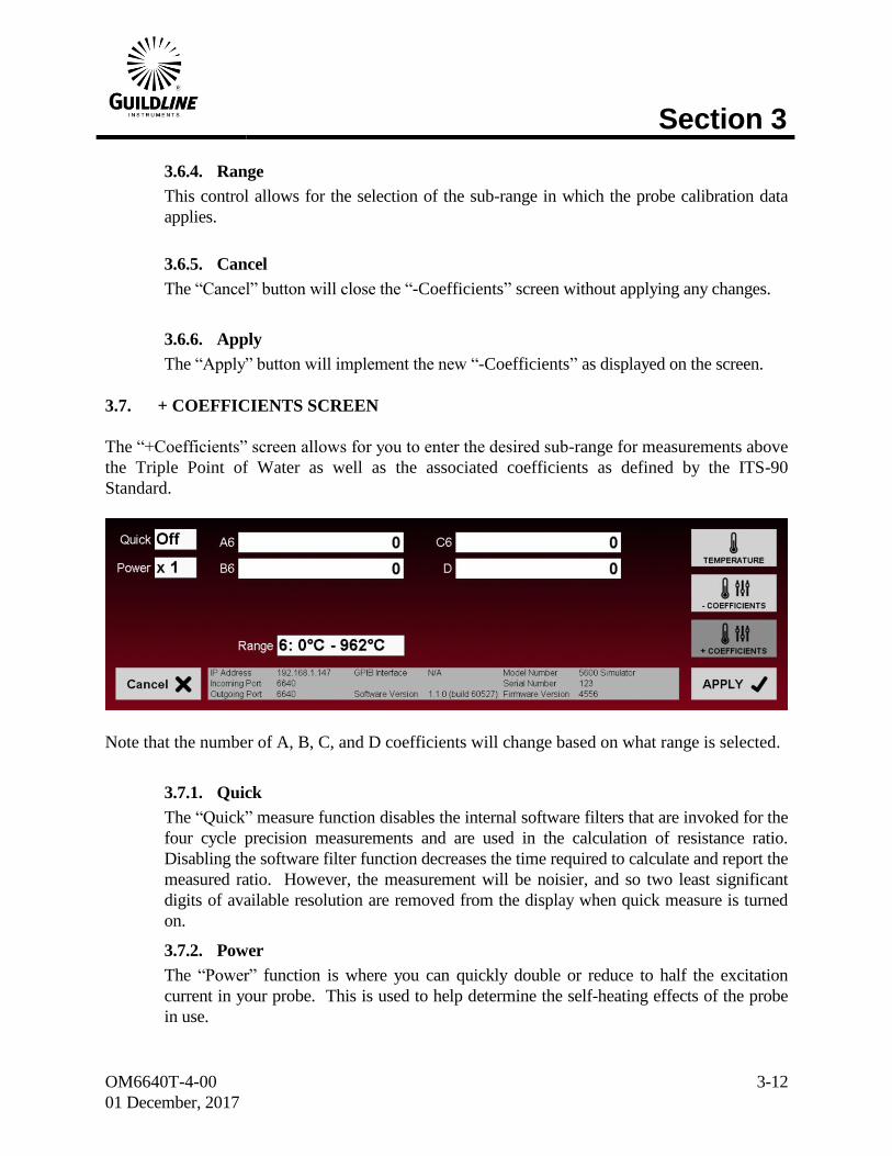
3.7. + COEFFICIENTS SCREEN
The “+Coefficients” screen allows for you to enter the desired sub-range for measurements above
the Triple Point of Water as well as the associated coefficients as defined by the ITS-90
Standard.
Note that the number of A, B, C, and D coefficients will change based on what range is selected.
3.7.1. Quick
The “Quick” measure function disables the internal software filters that are invoked for the
four cycle precision measurements and are used in the calculation of resistance ratio.
Disabling the software filter function decreases the time required to calculate and report the
measured ratio. However, the measurement will be noisier, and so two least significant
digits of available resolution are removed from the display when quick measure is turned
on.
3.7.2. Power
The “Power” function is where you can quickly double or reduce to half the excitation
current in your probe. This is used to help determine the self-heating effects of the probe
in use.
Section 3
OM6640T-4-00
01 December, 2017
3-13
3.7.3. A, B, C, and D Coefficients
Varying number of A, B, and C Coefficient fields button appears in “+Coefficients” screen
when using the ITS-90 Standard dependent on the sub-range selected. Select the
appropriate sub-range as listed on the calibration of the PRT and enter the corresponding
coefficients.
3.7.4. Range
This control allows for the selection of the sub-range in which the probe calibration data
applies.
3.7.5. Cancel
The “Cancel” button will close the “+Coefficients” screen without applying any changes.
3.7.6. Apply
The “Apply” button will implement the new “+Coefficients” as displayed on the screen.
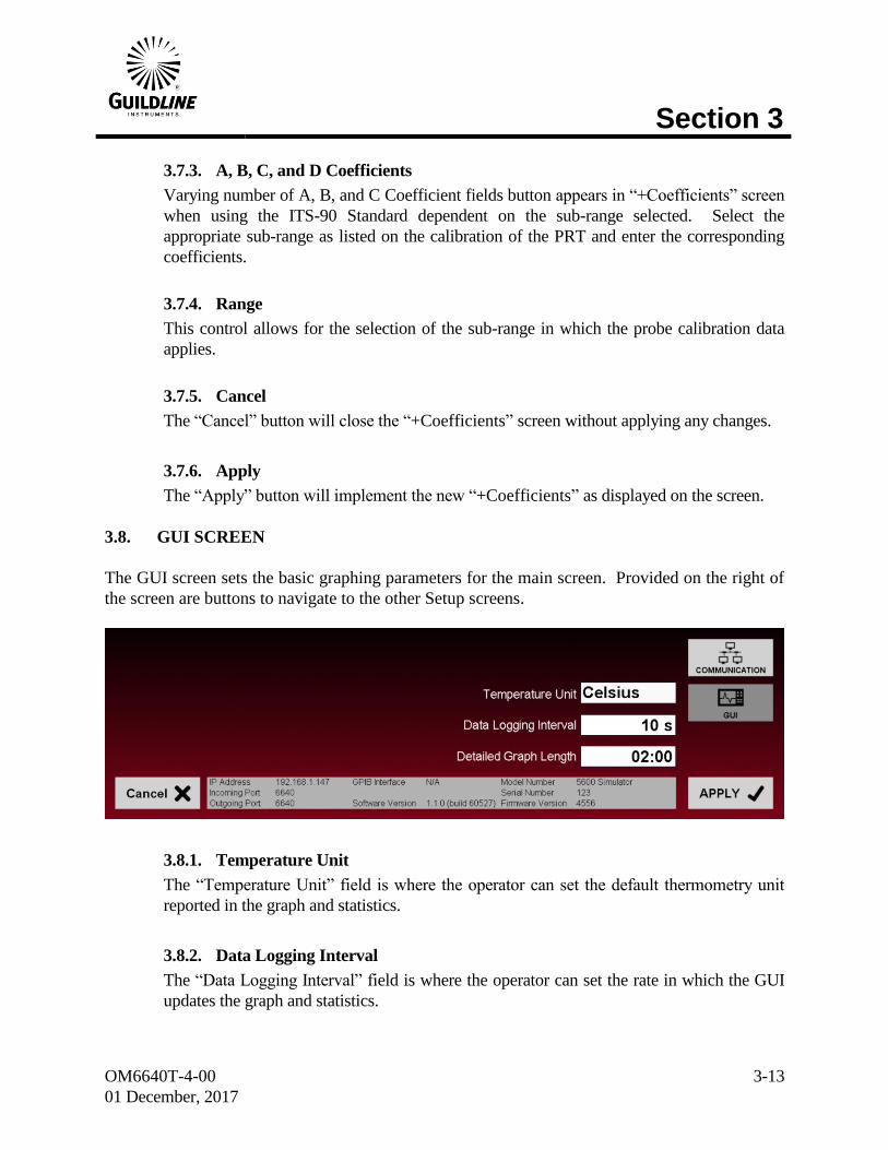
3.8. GUI SCREEN
The GUI screen sets the basic graphing parameters for the main screen. Provided on the right of
the screen are buttons to navigate to the other Setup screens.
3.8.1. Temperature Unit
The “Temperature Unit” field is where the operator can set the default thermometry unit
reported in the graph and statistics.
3.8.2. Data Logging Interval
The “Data Logging Interval” field is where the operator can set the rate in which the GUI
updates the graph and statistics.
Section 3
OM6640T-4-00
01 December, 2017
3-14
3.8.3. Detailed Graph Length
The “Detailed Graph Length” field is where the operator can set the length in time that
graph will display and for which statistics are calculated.
3.8.4. Cancel
The “Cancel” button will close the Setup screen.
3.8.5. Apply
The “Apply” button will implement the parameters as displayed on the screen.
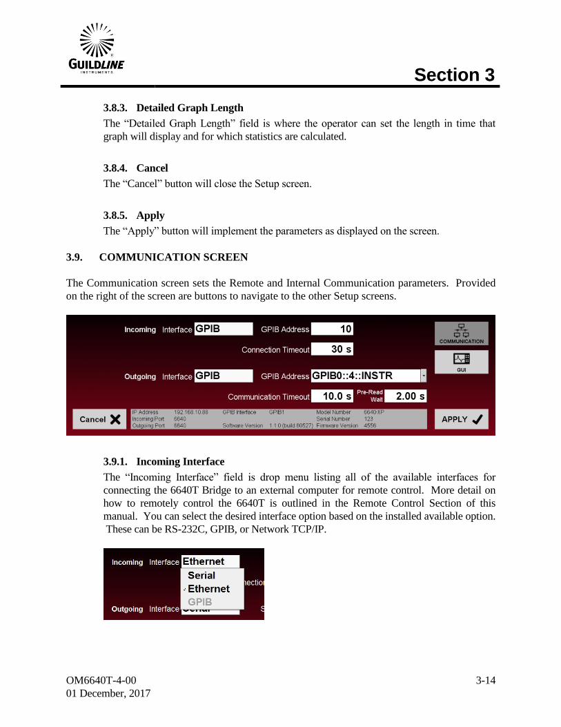
3.9. COMMUNICATION SCREEN
The Communication screen sets the Remote and Internal Communication parameters. Provided
on the right of the screen are buttons to navigate to the other Setup screens.
3.9.1. Incoming Interface
The “Incoming Interface” field is drop menu listing all of the available interfaces for
connecting the 6640T Bridge to an external computer for remote control. More detail on
how to remotely control the 6640T is outlined in the Remote Control Section of this
manual. You can select the desired interface option based on the installed available option.
These can be RS-232C, GPIB, or Network TCP/IP.

Section 3
OM6640T-4-00
01 December, 2017
3-15
3.9.2. Connection Timeout
The “Connection Timeout” field allows the operator to set the time the GUI will wait for a
connection from a remote PC before closing the active connection.
3.9.3. Outgoing Interface
The “Outgoing Interface” field is drop menu listing all of the available interfaces for
connecting the 6640 GUI to the 6640T internal hardware. You can select the desired
interface option based on the installed available option. These can be RS-232C, GPIB, or
Network TCP/IP. There is also a “Simulation” option which emulates a connection to the
6640T hardware.
3.9.4. Serial Port/GPIB Address/ IP Address
The “Serial Port” field (i.e. sometimes called “GPIB Address” or “IP Address”) is a drop
menu listing all of the available ports/addresses for connecting to the 6640T hardware.
Note that one of these fields will also appear next to the “Incoming Interface” depending
on what interface is chosen.
3.9.5. Communication Timeout
The “Communication Timeout” field allows the operator to set the time the GUI will wait
for a response from the 6640T hardware before reporting a connection error.
3.9.6. Cancel
The “Cancel” button will close the Setup screen without applying any changes.
3.9.7. Apply
The “Apply” button will implement the parameters as displayed on the screen.
Section 3
OM6640T-4-00
01 December, 2017
3-16
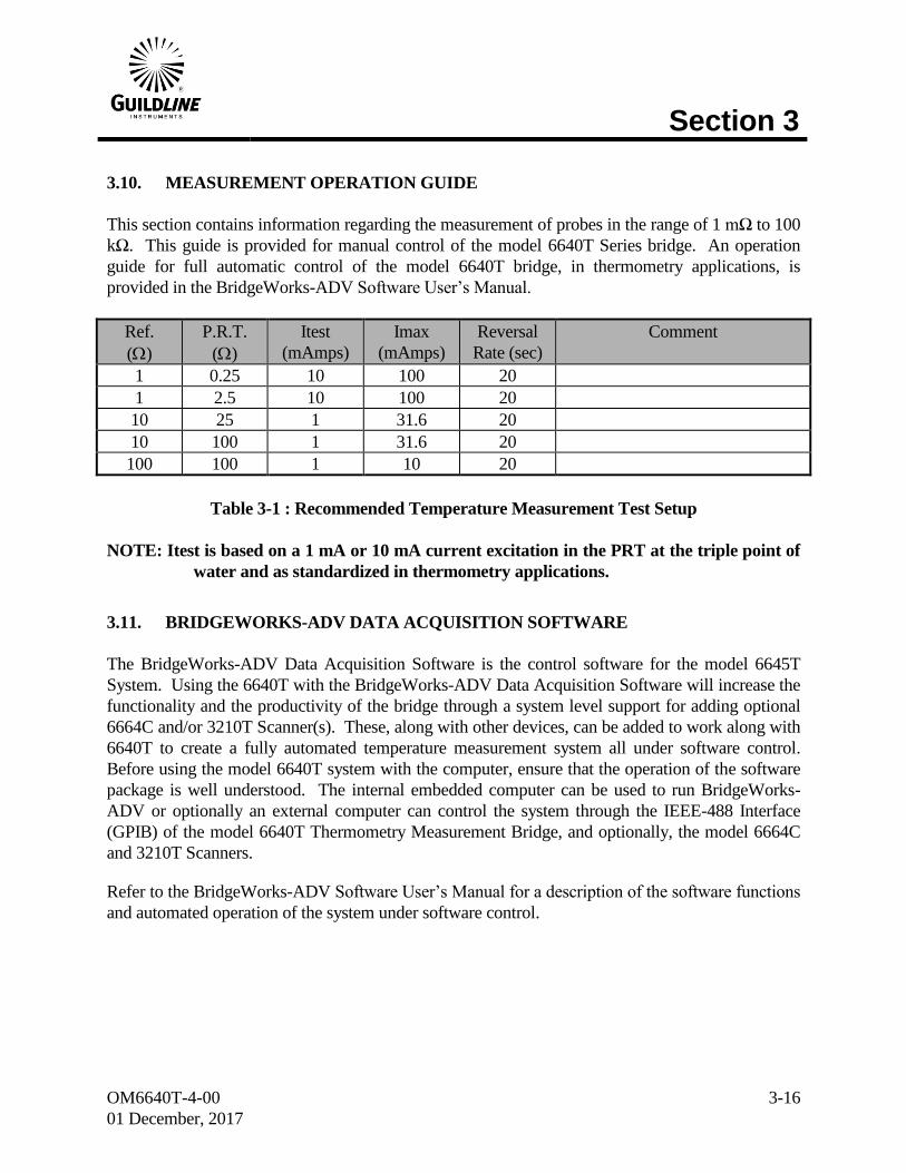
3.10. MEASUREMENT OPERATION GUIDE
This section contains information regarding the measurement of probes in the range of 1 mΩ to 100
kΩ. This guide is provided for manual control of the model 6640T Series bridge. An operation
guide for full automatic control of the model 6640T bridge, in thermometry applications, is
provided in the BridgeWorks-ADV Software User’s Manual.
Ref.
()
P.R.T.
()
Itest
(mAmps)
Imax
(mAmps)
Reversal
Rate (sec)
Comment
1 0.25 10 100 20
1 2.5 10 100 20
10 25 1 31.6 20
10 100 1 31.6 20
100 100 1 10 20
Table 3-1 : Recommended Temperature Measurement Test Setup
NOTE: Itest is based on a 1 mA or 10 mA current excitation in the PRT at the triple point of
water and as standardized in thermometry applications.
3.11. BRIDGEWORKS-ADV DATA ACQUISITION SOFTWARE
The BridgeWorks-ADV Data Acquisition Software is the control software for the model 6645T
System. Using the 6640T with the BridgeWorks-ADV Data Acquisition Software will increase the
functionality and the productivity of the bridge through a system level support for adding optional
6664C and/or 3210T Scanner(s). These, along with other devices, can be added to work along with
6640T to create a fully automated temperature measurement system all under software control.
Before using the model 6640T system with the computer, ensure that the operation of the software
package is well understood. The internal embedded computer can be used to run BridgeWorks-
ADV or optionally an external computer can control the system through the IEEE-488 Interface
(GPIB) of the model 6640T Thermometry Measurement Bridge, and optionally, the model 6664C
and 3210T Scanners.
Refer to the BridgeWorks-ADV Software User’s Manual for a description of the software functions
and automated operation of the system under software control.
Section 4
OM6640T-4-00
01 December, 2017
4-1
4. MAINTENANCE
4.1. INTRODUCTION
This section covers troubleshooting, repair and alignment of the model 6640T Series Automatic
DCC Resistance/Thermometry Bridge.
4.2. TEMPERATURE RATIO VERIFICATION
This section outlines the recommended thermometry based ratio verification requirements for the
model 6640T bridge.
4.2.1. PURPOSE
The purpose of the procedure in this section is to assure that the model 6640T Series Bridge
functions properly and meets the manufacturer’s specifications. It is recommended that these
procedures be performed after any corrective maintenance activity, or if the operator perceives a
problem.
It is recommended that all of these procedures be performed on an annual basis to verify
performance of the model 6640T and for its recertification.
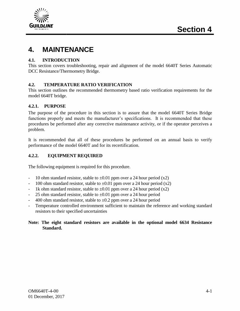
4.2.2. EQUIPMENT REQUIRED
The following equipment is required for this procedure.
- 10 ohm standard resistor, stable to ±0.01 ppm over a 24 hour period (x2)
- 100 ohm standard resistor, stable to ±0.01 ppm over a 24 hour period (x2)
- 1k ohm standard resistor, stable to ±0.01 ppm over a 24 hour period (x2)
- 25 ohm standard resistor, stable to ±0.01 ppm over a 24 hour period
- 400 ohm standard resistor, stable to ±0.2 ppm over a 24 hour period
- Temperature controlled environment sufficient to maintain the reference and working standard
resistors to their specified uncertainties
Note: The eight standard resistors are available in the optional model 6634 Resistance
Standard.
Section 4
OM6640T-4-00
01 December, 2017
4-2
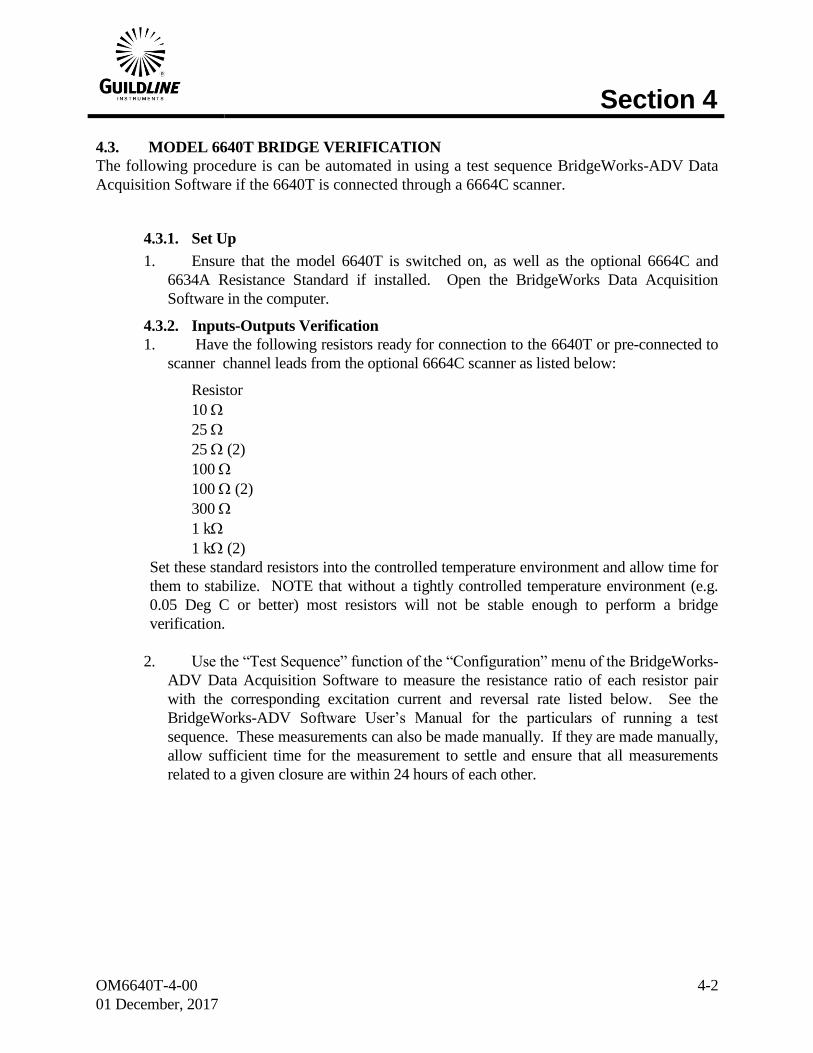
4.3. MODEL 6640T BRIDGE VERIFICATION
The following procedure is can be automated in using a test sequence BridgeWorks-ADV Data
Acquisition Software if the 6640T is connected through a 6664C scanner.
4.3.1. Set Up
1. Ensure that the model 6640T is switched on, as well as the optional 6664C and
6634A Resistance Standard if installed. Open the BridgeWorks Data Acquisition
Software in the computer.
4.3.2. Inputs-Outputs Verification
1. Have the following resistors ready for connection to the 6640T or pre-connected to
scanner channel leads from the optional 6664C scanner as listed below:
Resistor
10
25
25 (2)
100
100 (2)
300
1 k
1 k (2)
Set these standard resistors into the controlled temperature environment and allow time for
them to stabilize. NOTE that without a tightly controlled temperature environment (e.g.
0.05 Deg C or better) most resistors will not be stable enough to perform a bridge
verification.
2. Use the “Test Sequence” function of the “Configuration” menu of the BridgeWorks-
ADV Data Acquisition Software to measure the resistance ratio of each resistor pair
with the corresponding excitation current and reversal rate listed below. See the
BridgeWorks-ADV Software User’s Manual for the particulars of running a test
sequence. These measurements can also be made manually. If they are made manually,
allow sufficient time for the measurement to settle and ensure that all measurements
related to a given closure are within 24 hours of each other.
Section 4
OM6640T-4-00
01 December, 2017
4-3
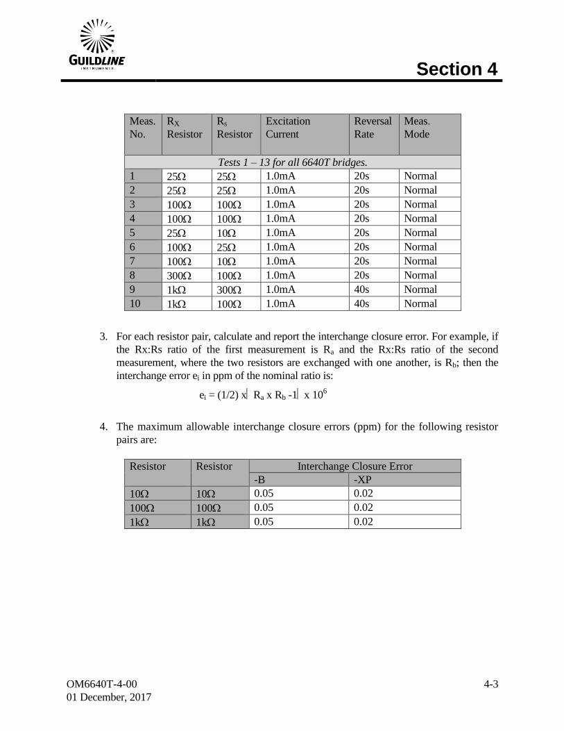
Meas.
No.
RX
Resistor
Rs
Resistor
Excitation
Current
Reversal
Rate
Meas.
Mode
Tests 1 – 13 for all 6640T bridges.
1 25 25 1.0mA 20s Normal
2 25 25 1.0mA 20s Normal
3 100 100 1.0mA 20s Normal
4 100 100 1.0mA 20s Normal
5 25 10 1.0mA 20s Normal
6 100 25 1.0mA 20s Normal
7 100 10 1.0mA 20s Normal
8 300 100 1.0mA 20s Normal
9 1k 300 1.0mA 40s Normal
10 1k 100 1.0mA 40s Normal
3. For each resistor pair, calculate and report the interchange closure error. For example, if
the Rx:Rs ratio of the first measurement is Ra and the Rx:Rs ratio of the second
measurement, where the two resistors are exchanged with one another, is Rb; then the
interchange error ei in ppm of the nominal ratio is:
ei = (1/2) x Ra x Rb -1 x 10⁶
4. The maximum allowable interchange closure errors (ppm) for the following resistor
pairs are:
Resistor Resistor Interchange Closure Error
-B -XP
10 10 0.05 0.02
100 100 0.05 0.02
1k 1k 0.05 0.02

Section 4
OM6640T-4-00
01 December, 2017
4-4
5. For the first 10:1 ladder up closure error (100:10), the 10:1 ratio must agree to within
the specification of the nominal ratio for either directly measuring the 10:1 ratio, or
calculating the ratio from the product of the 10:2.5 ratio and the 2.5:1 ratio, as
follows:
ei = (1/3) x Ra - Rb x Rc /10 x 106
Where:
Ra is the 10:1 ratio
Rb is the 2.5:1 ratio
Rc is the 10:2.5 ratio
6. For the second 10:1 ladder up closure error (1k:100), the 10:1 ratio must agree to
within the specification of the nominal ratio for either directly measuring the 10:1
ratio, or calculating the ratio from the product of the 10:4 ratio and the 4:1 ratio, as
follows:
ei = (1/3) x Ra - Rb x Rc /10 x 106
Where:
Ra is the 10:1 ratio
Rb is the 4:1 ratio
Rc is the 10:4 ratio
7. For the 100:1 ladder up closure error (1k:10), the 100:1 ratio must agree to within the
specification of the nominal ratio for either directly measuring the 100:1 ratio, or
calculating the ratio from the product of the 100:10 ratio and the 10:1 ratio, as
follows:
ei = (1/3) x Ra - Rb x Rc /100 x 106
Where:
Ra is the 100:1 ratio
Rb is the 100:10 ratio
Rc is the 10:1 ratio
8. The maximum allowable ladder up errors (ppm) for the following resistor sets are:
Resistor Resistor Resistor Ladder Closure Error
-B -XP
10 25 100 0.05 0.02
100 400 1k 0.05 0.02
10 100 1k 0.05 0.02

Section 5
OM6640T-4-00
01 December, 2017
5-1
5. REMOTE CONTROL
MODEL 6640 PROGRAMMING COMMAND SUMMARY
A brief description of each of the possible remote IEEE-488 commands and their syntax in BNF
(Backus Naur Form) follows:
- words inside angle brackets (ie. < and > ) are defined items
- :== means "is defined to be"
- | means "or"
- [] means optional
- required letters are shown in upper case but may be upper or lower case.
<digit> :== 0|1|2|3|4|5|6|7|8|9
<letter> :== A|B|C|...|Z|a|b|c|...|z
<string> :== <letter> | <letter><string>
<boolean> :== 0|1
<unsigned> :== <digit> | <digit><unsigned>
<nr1> :== [+|-]<unsigned>
<nr3> :== <nr1>[.[<unsigned>]][E<nr1>]
<?> :== <letter> | <digit>
<*> :== <?> | [<*>] :not to be confused with *
<DD> :== <unsigned> : limited to range 1...31
<MM> :== <unsigned> : limited to range 1...12
<YYYY> :== <unsigned> : limited to ranges 1999 and up
The STB Bits are as follows:
bit 7 = (unused)
bit 6 = SRQ (service request)
; set when (SRQ_mask|GPIB_STAT_PORT) != 0
bit 5 = ESB (event summary)
; set when bitwise AND of ESE, register is not zero
bit 4 = MAV (message available)
; set when GPIB Tx buffer has data available
; cleared when the buffer is empty
bit 3 = IFL (input buffer full)
; set when input buffer is over 80% full
; cleared when input buffer drops under 20% full
bit 2 = CHK (Checksum calculation complete)
bit 1 = RDY (ready)
; set when unit has a stable reading
; cleared when unit is working
bit 0 = OVR (over range)
; set when over range detected (in ISR)
; cleared when over range cleared
Section 5
OM6640T-4-00
01 December, 2017
5-2
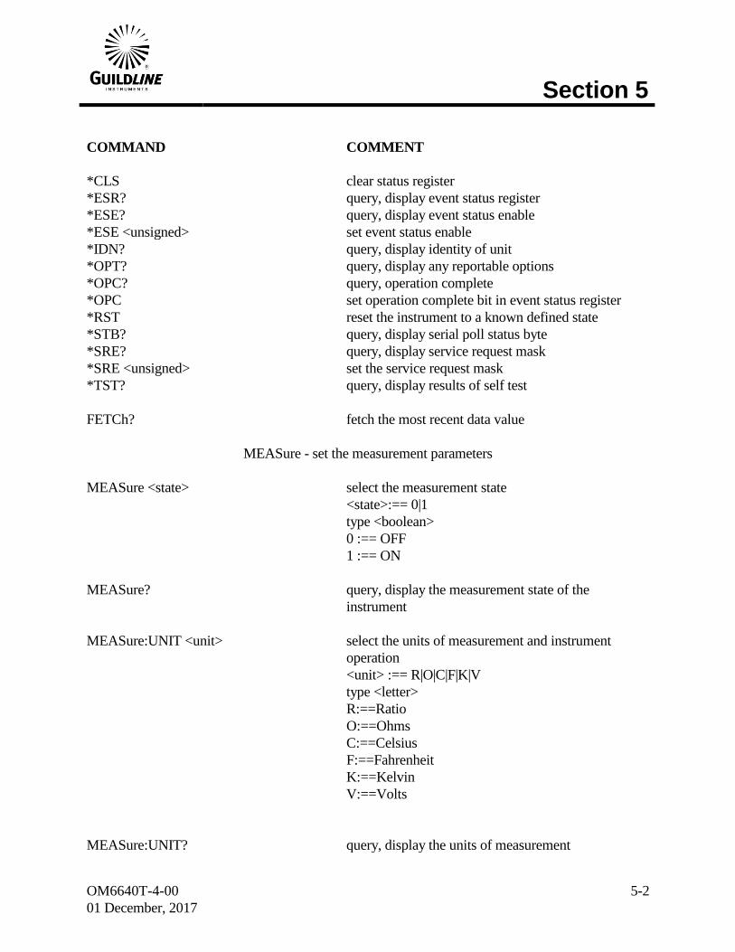
COMMAND COMMENT
*CLS clear status register
*ESR? query, display event status register
*ESE? query, display event status enable
*ESE <unsigned> set event status enable
*IDN? query, display identity of unit
*OPT? query, display any reportable options
*OPC? query, operation complete
*OPC set operation complete bit in event status register
*RST reset the instrument to a known defined state
*STB? query, display serial poll status byte
*SRE? query, display service request mask
*SRE <unsigned> set the service request mask
*TST? query, display results of self test
FETCh? fetch the most recent data value
MEASure - set the measurement parameters
MEASure <state> select the measurement state
<state>:== 0|1
type <boolean>
0 :== OFF
1 :== ON
MEASure? query, display the measurement state of the
instrument
MEASure:UNIT <unit> select the units of measurement and instrument
operation
<unit> :== R|O|C|F|K|V
type <letter>
R:==Ratio
O:==Ohms
C:==Celsius
F:==Fahrenheit
K:==Kelvin
V:==Volts
MEASure:UNIT? query, display the units of measurement

Section 5
OM6640T-4-00
01 December, 2017
5-3
COMMAND COMMENT
MEASure:FILTer <function> setup the digital filter for the display data
<function>:== 0|1|2
type <digit>
0 :== Filter OFF
1 :== Decimation
2 :== Simple average
MEASure:FILTer? query, display the filter setup
MEASure:UPDAte <rate> set the number of screen updates for each
measurement cycle
<rate>:== 0|1|2
type <digit>
0:==1 updates/cycle
1:==2 updates/cycle
2:==4 updates/cycle
MEASure:UPDAte? query, display the screen update rate setting
MEASure:DEVIation <diff> select the method of reporting the difference data
<diff>:==0|1|2|3|4
type <digit>
0 :== disable/normal
1 :== parts per million
2 :== delta change
3 :== ppm from datum
4 :== delta from datum
MEASure:DEVIation? query, display the method of reporting the difference
data
MEASure:RESOlution <prec> select the precision of reporting the data
<prec>:==0|1|2|3|4
type <digit>
0 :== 0.001 ppm
1 :== 0.01 ppm
2 :== 0.1 ppm
3 :== 1.0 ppm
4 :== 10.0 ppm
MEASure:RESOlution? query, display the precision of reporting the data
Section 5
OM6640T-4-00
01 December, 2017
5-4
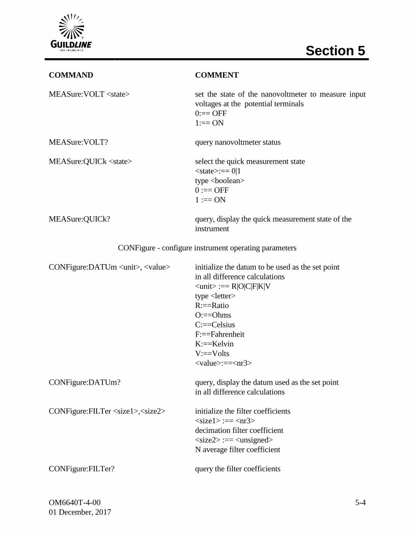
COMMAND COMMENT
MEASure:VOLT <state> set the state of the nanovoltmeter to measure input
voltages at the potential terminals
0:== OFF
1:== ON
MEASure:VOLT? query nanovoltmeter status
MEASure:QUICk <state> select the quick measurement state
<state>:== 0|1
type <boolean>
0 :== OFF
1 :== ON
MEASure:QUICk? query, display the quick measurement state of the
instrument
CONFigure - configure instrument operating parameters
CONFigure:DATUm <unit>, <value> initialize the datum to be used as the set point
in all difference calculations
<unit> :== R|O|C|F|K|V
type <letter>
R:==Ratio
O:==Ohms
C:==Celsius
F:==Fahrenheit
K:==Kelvin
V:==Volts
<value>:==<nr3>
CONFigure:DATUm? query, display the datum used as the set point
in all difference calculations
CONFigure:FILTer <size1>,<size2> initialize the filter coefficients
<size1> :== <nr3>
decimation filter coefficient
<size2> :== <unsigned>
N average filter coefficient
CONFigure:FILTer? query the filter coefficients

Section 5
OM6640T-4-00
01 December, 2017
5-5
COMMAND COMMENT
CONFigure:RESIstor <md>, <RS_SN>, <SN>, <RX>, <Rev_Rate>, <Tst_Val>, <Tst_Max>
set the active resistor measurement
configuration
<mode>:== 0|1|2|
type <digit>
0:==normal mode
1:==high ohms mode
2:==low ohms mode
<RS>:==<nr3>
ref. resistor value
<RS_SN>:==<string>
ref. resistor serial #
<RX>:==<nr3>
approximate value Rx
<Rev_rate>:==<nr3>
test current reversal rate
<Tst_Val>:==<nr3>
test current/volts
<Tst_Max>:==<nr3>
max current(Is)/volts for ref resistor
CONFigure:RESIstor? query, display active resistor configuration
information
Section 5
OM6640T-4-00
01 December, 2017
5-6
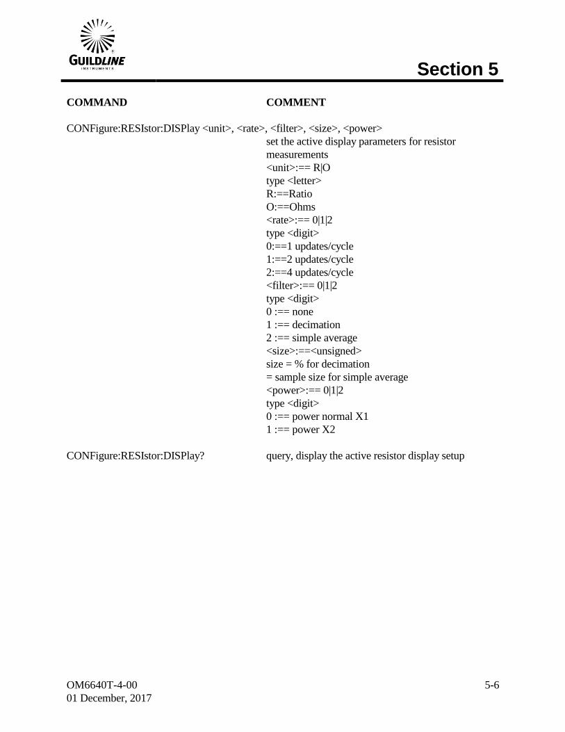
COMMAND COMMENT
CONFigure:RESIstor:DISPlay <unit>, <rate>, <filter>, <size>, <power>
set the active display parameters for resistor
measurements
<unit>:== R|O
type <letter>
R:==Ratio
O:==Ohms
<rate>:== 0|1|2
type <digit>
0:==1 updates/cycle
1:==2 updates/cycle
2:==4 updates/cycle
<filter>:== 0|1|2
type <digit>
0 :== none
1 :== decimation
2 :== simple average
<size>:==<unsigned>
size = % for decimation
= sample size for simple average
<power>:== 0|1|2
type <digit>
0 :== power normal X1
1 :== power X2
CONFigure:RESIstor:DISPlay? query, display the active resistor display setup
Section 5
OM6640T-4-00
01 December, 2017
5-7
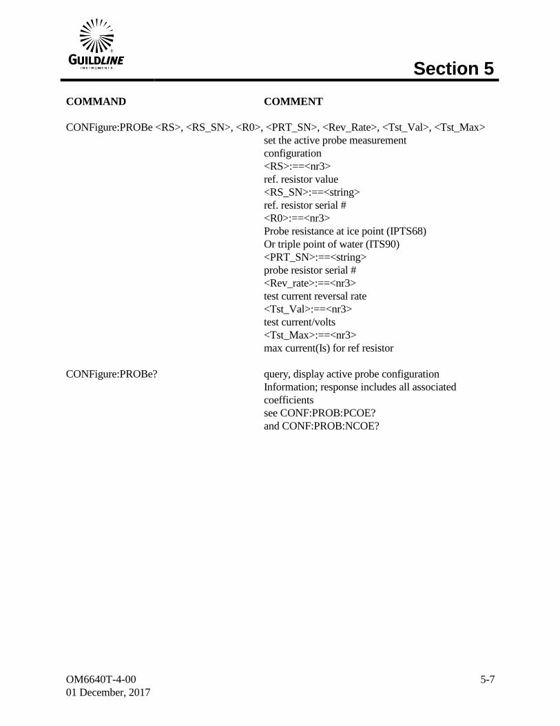
COMMAND COMMENT
CONFigure:PROBe <RS>, <RS_SN>, <R0>, <PRT_SN>, <Rev_Rate>, <Tst_Val>, <Tst_Max>
set the active probe measurement
configuration
<RS>:==<nr3>
ref. resistor value
<RS_SN>:==<string>
ref. resistor serial #
<R0>:==<nr3>
Probe resistance at ice point (IPTS68)
Or triple point of water (ITS90)
<PRT_SN>:==<string>
probe resistor serial #
<Rev_rate>:==<nr3>
test current reversal rate
<Tst_Val>:==<nr3>
test current/volts
<Tst_Max>:==<nr3>
max current(Is) for ref resistor
CONFigure:PROBe? query, display active probe configuration
Information; response includes all associated
coefficients
see CONF:PROB:PCOE?
and CONF:PROB:NCOE?
Section 5
OM6640T-4-00
01 December, 2017
5-8
COMMAND COMMENT
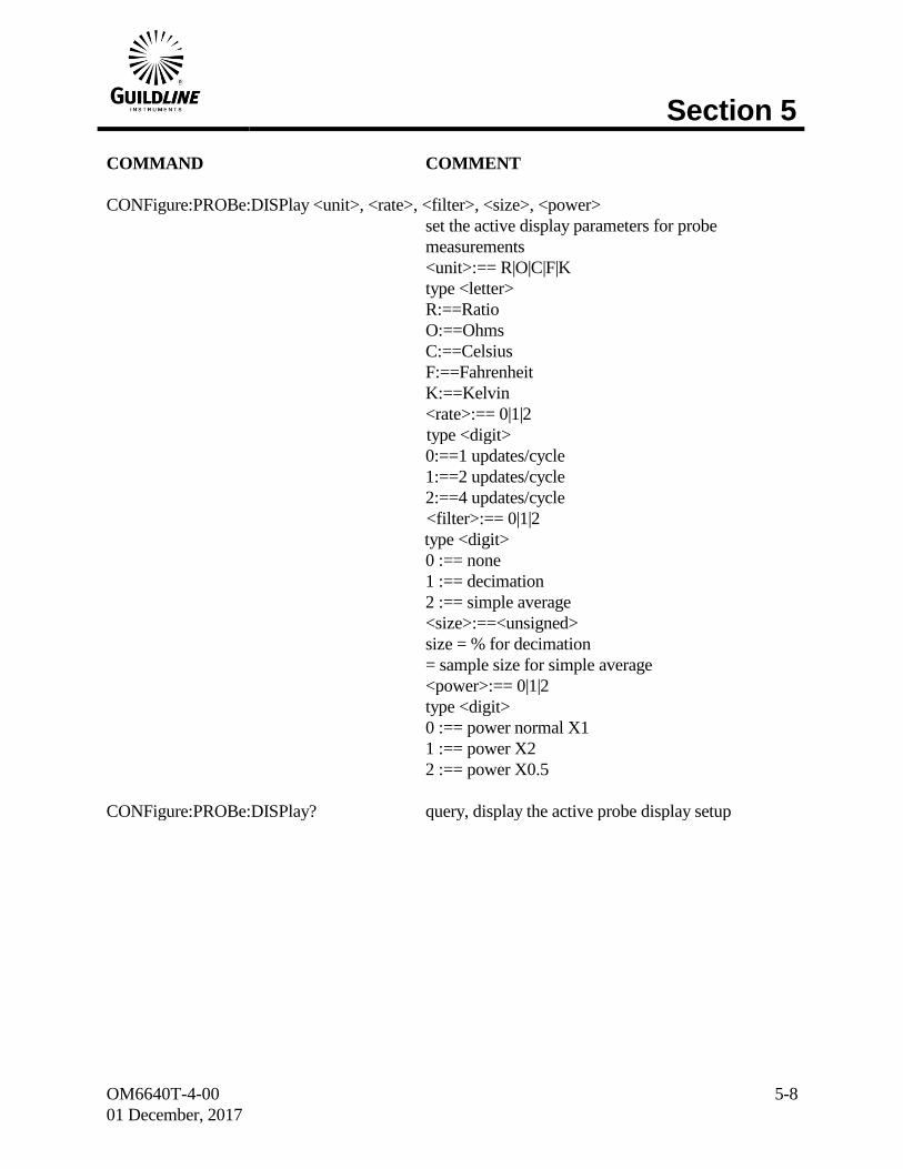
CONFigure:PROBe:DISPlay <unit>, <rate>, <filter>, <size>, <power>
set the active display parameters for probe
measurements
<unit>:== R|O|C|F|K
type <letter>
R:==Ratio
O:==Ohms
C:==Celsius
F:==Fahrenheit
K:==Kelvin
<rate>:== 0|1|2
type <digit>
0:==1 updates/cycle
1:==2 updates/cycle
2:==4 updates/cycle
<filter>:== 0|1|2
type <digit>
0 :== none
1 :== decimation
2 :== simple average
<size>:==<unsigned>
size = % for decimation
= sample size for simple average
<power>:== 0|1|2
type <digit>
0 :== power normal X1
1 :== power X2
2 :== power X0.5
CONFigure:PROBe:DISPlay? query, display the active probe display setup

Section 5
OM6640T-4-00
01 December, 2017
5-9
COMMAND COMMENT
CONFigure:PROBe:COEFficient <equation_#>, <coeff_00>, <coeff_01>, .., <coeff_n>
set the active probe conversion coefficients
measurements
<equation_#>:== <unsigned>:
equation_# takes on a value in the range 00 through
11 for the temperature calibration range of the probe
<coeff_00>:==<nr3>
<coeff_xx> are coefficients 01 through n for the
probe ITS90 conversion algorithm.
When <equation>:==00 the IPTS68 coefficients can
be set.
CONFigure:PROBe:PositiveCOEfficient? query, display the active probe positive
temperature coefficients
CONFigure:PROBe:NegativeCOEfficient? query, display the active probe negative
temperature coefficients
CONFigure:VOLTmeter <range>, <zero>, <high>, <ref>
set the voltmeter calibration coefficients
<range>:== 0|1|2|3|4
type <digit>
0:== 20V range
1:== 2V range
2:== 200mV range
3:== 20mV range
4:== 2mV range
<zero>:==<unsigned>
<high>:==<unsigned>
<ref>:==<nr1>
CONFigure:VOLTmeter? <Range> query, display the voltmeter calibration setup
<range>:== 0|1|2|3|4
type <digit>
0:== 20V range
1:== 2V range
2:== 200mV range
3:== 20mV range
4:== 2mV range
Section 5
OM6640T-4-00
01 December, 2017
5-10
COMMAND COMMENT
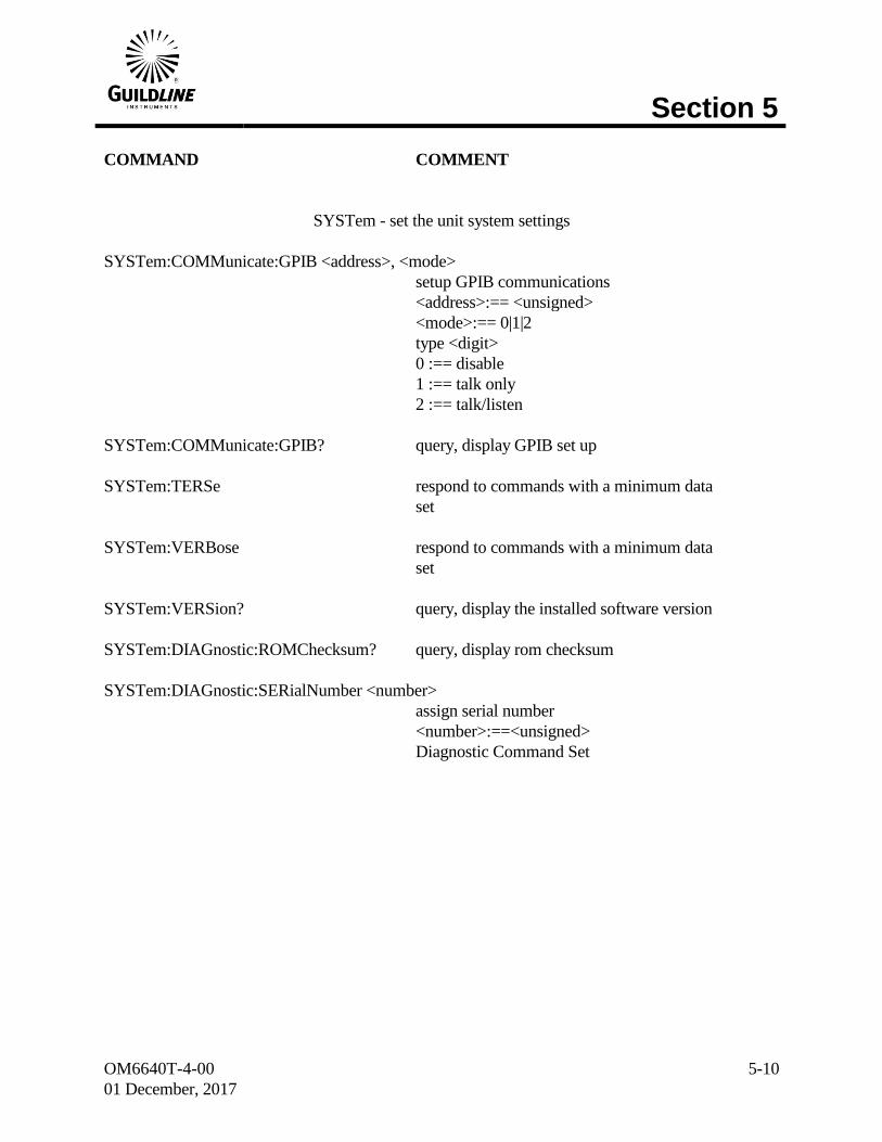
SYSTem - set the unit system settings
SYSTem:COMMunicate:GPIB <address>, <mode>
setup GPIB communications
<address>:== <unsigned>
<mode>:== 0|1|2
type <digit>
0 :== disable
1 :== talk only
2 :== talk/listen
SYSTem:COMMunicate:GPIB? query, display GPIB set up
SYSTem:TERSe respond to commands with a minimum data
set
SYSTem:VERBose respond to commands with a minimum data
set
SYSTem:VERSion? query, display the installed software version
SYSTem:DIAGnostic:ROMChecksum? query, display rom checksum
SYSTem:DIAGnostic:SERialNumber <number>
assign serial number
<number>:==<unsigned>
Diagnostic Command Set
Section 5
OM6640T-4-00
01 December, 2017
5-11
COMMAND COMMENT
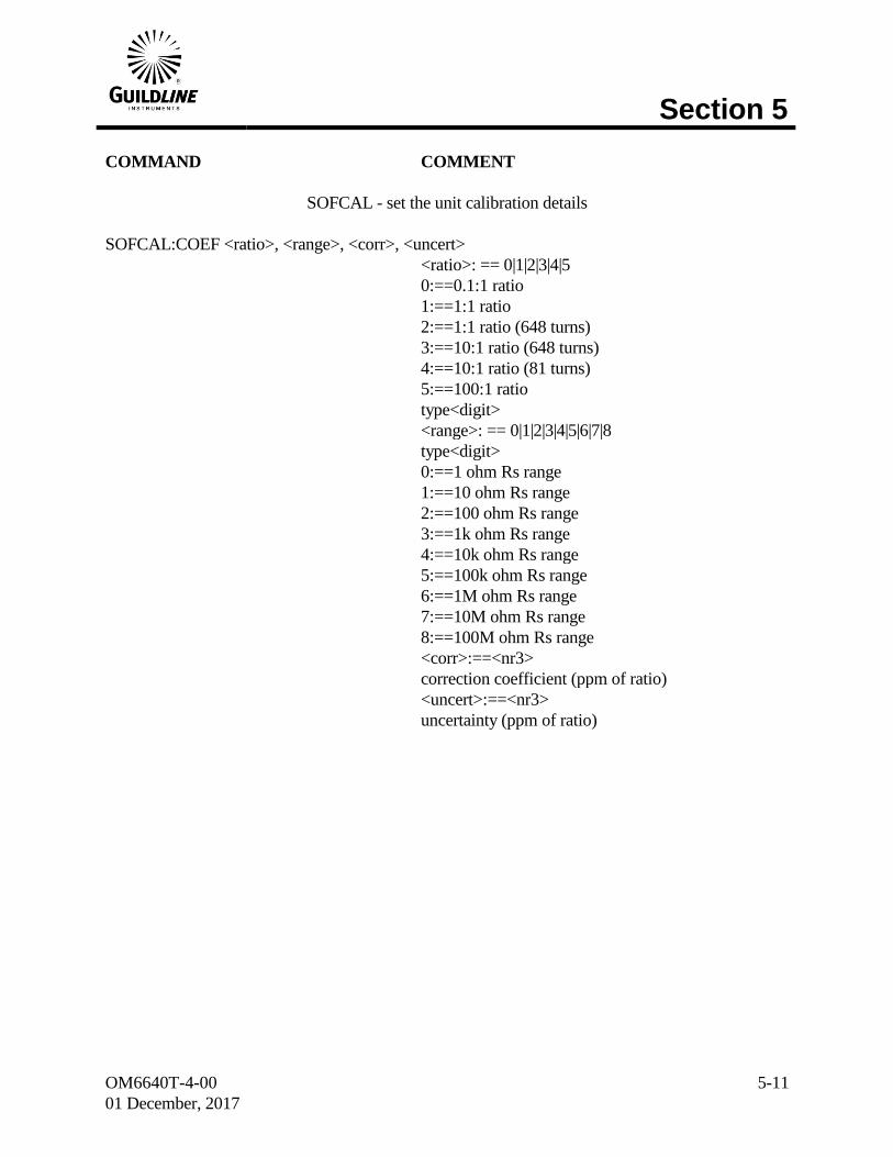
SOFCAL - set the unit calibration details
SOFCAL:COEF <ratio>, <range>, <corr>, <uncert>
<ratio>: == 0|1|2|3|4|5
0:==0.1:1 ratio
1:==1:1 ratio
2:==1:1 ratio (648 turns)
3:==10:1 ratio (648 turns)
4:==10:1 ratio (81 turns)
5:==100:1 ratio
type<digit>
<range>: == 0|1|2|3|4|5|6|7|8
type<digit>
0:==1 ohm Rs range
1:==10 ohm Rs range
2:==100 ohm Rs range
3:==1k ohm Rs range
4:==10k ohm Rs range
5:==100k ohm Rs range
6:==1M ohm Rs range
7:==10M ohm Rs range
8:==100M ohm Rs range
<corr>:==<nr3>
correction coefficient (ppm of ratio)
<uncert>:==<nr3>
uncertainty (ppm of ratio)
Section 5
OM6640T-4-00
01 December, 2017
5-12
COMMAND COMMENT
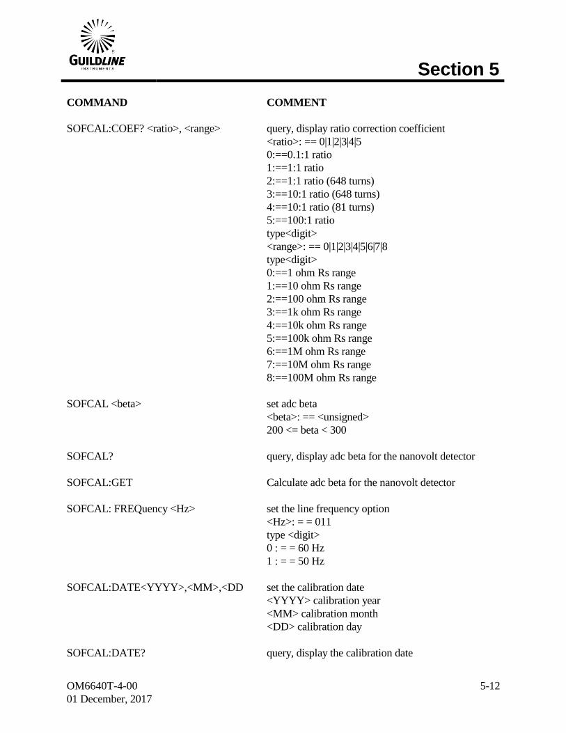
SOFCAL:COEF? <ratio>, <range> query, display ratio correction coefficient
<ratio>: == 0|1|2|3|4|5
0:==0.1:1 ratio
1:==1:1 ratio
2:==1:1 ratio (648 turns)
3:==10:1 ratio (648 turns)
4:==10:1 ratio (81 turns)
5:==100:1 ratio
type<digit>
<range>: == 0|1|2|3|4|5|6|7|8
type<digit>
0:==1 ohm Rs range
1:==10 ohm Rs range
2:==100 ohm Rs range
3:==1k ohm Rs range
4:==10k ohm Rs range
5:==100k ohm Rs range
6:==1M ohm Rs range
7:==10M ohm Rs range
8:==100M ohm Rs range
SOFCAL <beta> set adc beta
<beta>: == <unsigned>
200 <= beta < 300
SOFCAL? query, display adc beta for the nanovolt detector
SOFCAL:GET Calculate adc beta for the nanovolt detector
SOFCAL: FREQuency <Hz> set the line frequency option
<Hz>: = = 011
type <digit>
0 : = = 60 Hz
1 : = = 50 Hz
SOFCAL:DATE<YYYY>,<MM>,<DD set the calibration date
<YYYY> calibration year
<MM> calibration month
<DD> calibration day
SOFCAL:DATE? query, display the calibration date
Section 5
OM6640T-4-00
01 December, 2017
5-13
COMMAND COMMENT
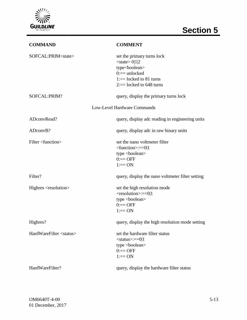
SOFCAL:PRIM<state> set the primary turns lock
<state> 0|1|2
type<boolean>
0:== unlocked
1:== locked to 81 turns
2:== locked to 648 turns
SOFCAL:PRIM? query, display the primary turns lock
Low-Level Hardware Commands
ADconvRead? query, display adc reading in engineering units
ADconvB? query, display adc in raw binary units
Filter <function> set the nano voltmeter filter
<function>:==0|1
type <boolean>
0:== OFF
1:== ON
Filter? query, display the nano voltmeter filter setting
Highres <resolution> set the high resolution mode
<resolution>:==0|1
type <boolean>
0:== OFF
1:== ON
Highres? query, display the high resolution mode setting
HardWareFilter <status> set the hardware filter status
<status>:==0|1
type <boolean>
0:== OFF
1:== ON
HardWareFilter? query, display the hardware filter status
Section 5
OM6640T-4-00
01 December, 2017
5-14
COMMAND COMMENT
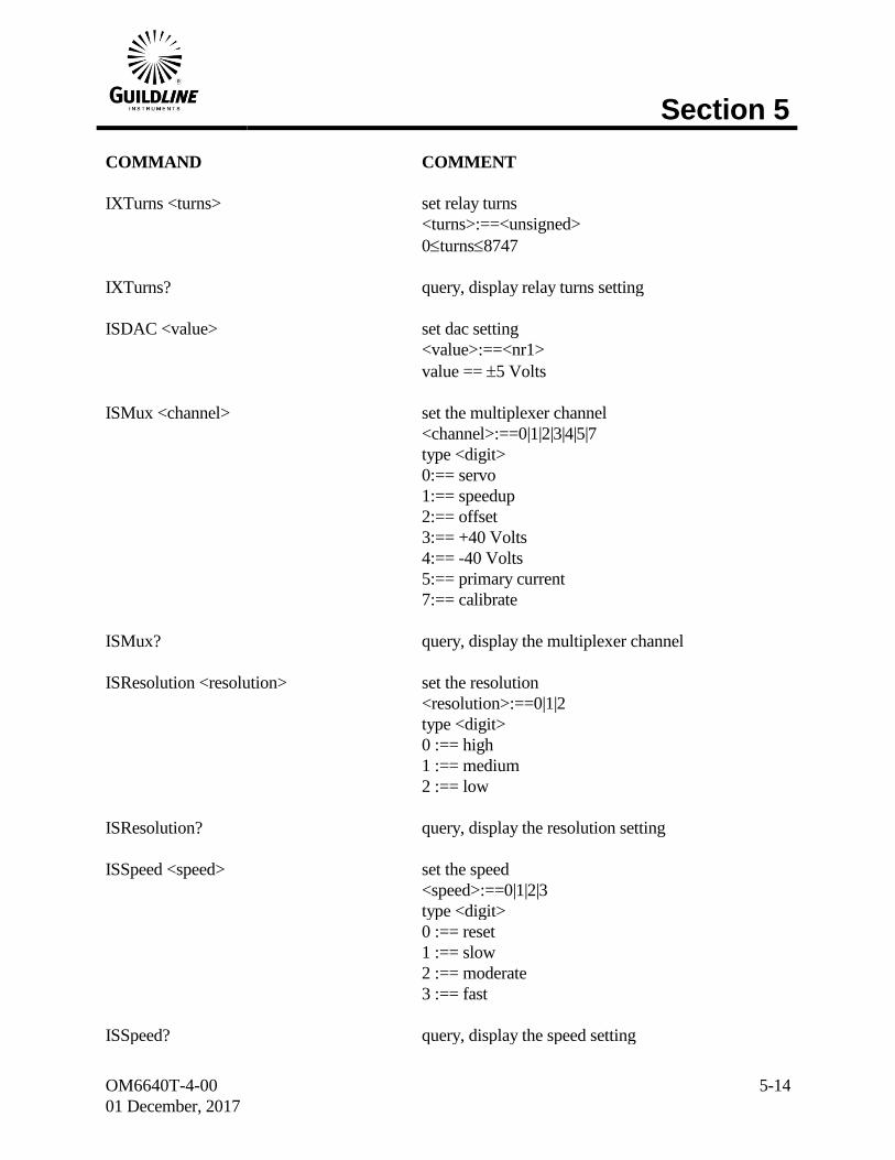
IXTurns <turns> set relay turns
<turns>:==<unsigned>
0turns8747
IXTurns? query, display relay turns setting
ISDAC <value> set dac setting
<value>:==<nr1>
value == 5 Volts
ISMux <channel> set the multiplexer channel
<channel>:==0|1|2|3|4|5|7
type <digit>
0:== servo
1:== speedup
2:== offset
3:== +40 Volts
4:== -40 Volts
5:== primary current
7:== calibrate
ISMux? query, display the multiplexer channel
ISResolution <resolution> set the resolution
<resolution>:==0|1|2
type <digit>
0 :== high
1 :== medium
2 :== low
ISResolution? query, display the resolution setting
ISSpeed <speed> set the speed
<speed>:==0|1|2|3
type <digit>
0 :== reset
1 :== slow
2 :== moderate
3 :== fast
ISSpeed? query, display the speed setting
Section 5
OM6640T-4-00
01 December, 2017
5-15
COMMAND COMMENT
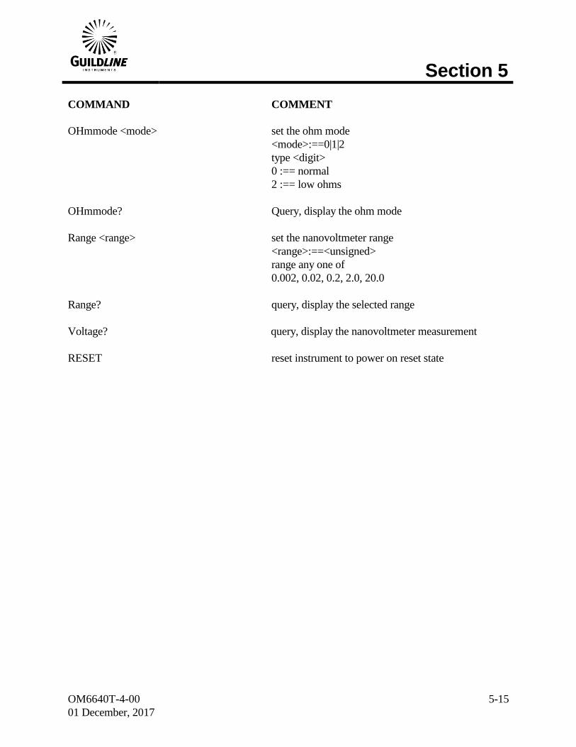
OHmmode <mode> set the ohm mode
<mode>:==0|1|2
type <digit>
0 :== normal
2 :== low ohms
OHmmode? Query, display the ohm mode
Range <range> set the nanovoltmeter range
<range>:==<unsigned>
range any one of
0.002, 0.02, 0.2, 2.0, 20.0
Range? query, display the selected range
Voltage? query, display the nanovoltmeter measurement
RESET reset instrument to power on reset state