OPERATOR'S MANUAL For DDAD30HC-11 Series Dryers · POUR VOTRE SÉCURITÉ Ne pas entreposer ni...
24
8514-154-001A October 2011 OPERATOR'S MANUAL For DDAD30HC-11 Series Dryers The dryer must not be stored or installed where it will be exposed to water and/or weather. WARNING: For your safety the information in this manual must be followed to minimize the risk of fire or explosion or to prevent property damage, personal injury or death. -Do not store or use gasoline or other flammable vapors and liquids in the vicinity of this or any other appliance. -WHAT TO DO IF YOU SMELL GAS -Do not try to light any appliance. -Do not touch any electrical switch: do not use any telephone in your building. -Clear the room, building or area of all occupants. -Immediately call your gas supplier from a neighbor’s telephone. Follow the gas supplier’s instructions. -If you cannot reach your gas supplier, call the fire department. Installation and service must be performed by a qualified installer, service agency or the gas supplier. You, the purchaser, must post in a prominent location instructions to be followed in the event the user smells gas. Consult your local gas supplier for procedure to be followed if the odor of gas is present. Post the following “For Your Safety” caution in a prominent location: FOR YOUR SAFETY Do not store or use gasoline or other flammable vapors or liquids in the vicinity of this or any other appliance. FOR YOUR SAFETY THIS MACHINE IS FOR DRYING ONLY FABRICS CLEANED IN WATER. To avoid possibility of fire, including spontaneous combustion, do not dry oiled floor mops, items containing foam rubber or similarly textured rubberlike materials or any material on which you have used a cleaning solvent or which contains flammable liquids or solids (such as gasoline, kerosene, waxes, etc.) It is important that you read this Manual and retain it for future reference. For service or replacement parts, contact the distributor in your area or: Dexter Laundry, Inc 2211 W. Grimes Fairfield, Iowa 52556
Transcript of OPERATOR'S MANUAL For DDAD30HC-11 Series Dryers · POUR VOTRE SÉCURITÉ Ne pas entreposer ni...

8514-154-001A October 2011
OPERATOR'S MANUAL
For DDAD30HC-11 Series Dryers The dryer must not be stored or installed where it will be exposed to water and/or weather.
WARNING: For your safety the information in this manual must be followed to minimize the risk of fire or explosion or to prevent property damage, personal injury or death.
-Do not store or use gasoline or other flammable vapors and liquids in the vicinity of this or any other appliance. -WHAT TO DO IF YOU SMELL GAS
-Do not try to light any appliance. -Do not touch any electrical switch: do not use any telephone in your building. -Clear the room, building or area of all occupants. -Immediately call your gas supplier from a neighbor’s telephone. Follow the
gas supplier’s instructions. -If you cannot reach your gas supplier, call the fire department.
Installation and service must be performed by a qualified installer, service agency or the gas supplier.
You, the purchaser, must post in a prominent location instructions to be followed in the event the user smells gas. Consult your local gas supplier for procedure to be followed if the odor of gas is present.
Post the following “For Your Safety” caution in a prominent location:
FOR YOUR SAFETY
Do not store or use gasoline or other flammable vapors or liquids in the vicinity of this or any other appliance.
FOR YOUR SAFETY THIS MACHINE IS FOR DRYING ONLY FABRICS CLEANED IN WATER. To avoid possibility of fire, including spontaneous combustion, do not dry oiled floor mops, items containing foam rubber or similarly textured rubberlike materials or any material on which you have used a cleaning solvent or which contains flammable liquids or solids (such as gasoline, kerosene, waxes, etc.)
It is important that you read this Manual and retain it for future reference. For service or replacement parts, contact the distributor in your area or:
Dexter Laundry, Inc 2211 W. Grimes
Fairfield, Iowa 52556
2
French Language Warnings
POUR VOTRE SÉCURITÉ
Ne pas entreposer ni utiliser d’essence ni d’autres vapeurs ou liquides inflammables dans le voisinage de cet appareil ou de tout autre appareil. I. QUE FAIRE SI VOUS SENTEZ UNE ODEUR DE GAZ: • Ne pas tenter d’allumer d’appareil. • Ne touchez à aucun interrupteur. Ne pas vous servir des téléphones se trouvant
dans le bâtiment oú vous vous trouvez. • Évacuez la pièce, le bâtiment ou la zone. • Appelez immédiatement votre fournisseour de gaz depuis un voisin. Suivez les
instructions du fournisseur. • Si vous ne pouvez rejoindre le founisseur de gaz, appelez le service des incendies. L’installation et l’entretien doivent être assurés par un installateur ou un service d’entretien qualifié ou par le fournisseur de gaz.
Ne pas enteposer ni utiliser d’essence ni d’autres vapeurs ou liquides inflammables dan le voisinage de cet appareil ou de tout autre appareil.
AVERTISSEMENT. Assurez-vous de bien suivre les instructions données dans cette notice pour réduire au minimum le risque d’incendie ou d’explosion ou pour éviter tout dommage matériel, toute blessure ou la mort.

3
TABLE OF CONTENTS
DRYER DIMENSIONS (Figure 1) 4
UNCRATING 5
INSTALLATION CLEARANCE (Figure 2) 6
DRYER EXHAUST SYSTEM (Figure 3) 9
DRYER SHUTDOWN 9
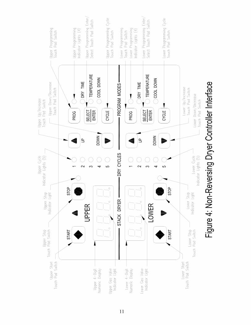
TOUCH PAD LAYOUT (Figure 4) 11
DRYER DEFAULT SETTINGS 12
DRYER FAULT CODES 12
TOUCH PAD DESCRIPTION 13
OPERATING INSTRUCTIONS 15
PROGRAMMING INSTRUCTIONS 17
SERVICING DRYER 23
PREVENTATIVE MAINTENANCE 23
WARNINGS ABOUT USE AND OPERATION
It is ABSOLUTELY ESSENTIAL that the dryer be grounded to a known earth (zero) ground in accordance with local codes or, in the absence of local codes, with the latest editions of the National Electric Code, ANSI//NFPA 70 or Standard CSA C22.1 Canadian Electrical Code Part 1. This is not only for personal safety, but is necessary for proper operation of the controller. Failure to do so will void the warranty of the controller. KEEP SHIELDS, GUARDS AND COVERS IN PLACE. These safety devices are provided to protect everyone from injury. THIS DRYER IS EQUIPPED WITH A MANUALLY RESETTABLE OVER-TEMPERATURE THERMOSTAT located on the end of the burner housing above the gas valve. Should the dryer cease to operate, refer to your “Service Procedure and Parts Data” book for instructions. CHECK THIS THERMOSTAT WHEN INSTALLING DRYER to assure it is not tripped. Impacts, such as rough handling in shipment, may trip the thermostat. It may be reset by inserting a wooden (nonconductive) pencil or dowel through the guide bushing in the cover. NOTE: THIS APPLIANCE SHALL NOT BE USED TO DRY OFF SOLVENTS OR DRY-CLEANING FLUIDS.

4

5
INSTALLATION AND OPERATING INSTRUCTIONS UNCRATING AND PLACING DRYER Tools Required: 3/4" (19 mm) hex socket & ratchet driver, wood block 4" (100 mm) or 5" (125 mm) thick, a knife and a groove joint pliers, which will open to 1 3/8" (35 mm). 1. Remove and discard packaging.
2. The crate base is attached to the dryer by (4) cap screws driven upward from below the crate
base. Remove crate base from dryer, by tipping dryer sidewise and place block under crate base rail in center of dryer. Using a ratchet and 3/4" (19 mm) hex socket, remove and discard (2) crating bolts from side, which is raised. Remove block from under crate base. Repeat for other side.
3. Install leveling legs. Using a walking motion, move dryer sideways about 6" (150 mm) off
crate base. Tip dryer up and place block under edge of dryer. Thread two leveling legs about two-thirds into the T-nuts on the base from which the crating bolts were removed. Remove block from under dryer.
With a walking motion move dryer completely off crate base. Discard crate base.
Tip dryer sidewise, as previously done, and place block under edge of dryer on raised side. Thread leveling legs into nuts as was done for the first side.
Slide unit into position where it will be installed. Adjust leveling legs, using the groove joint pliers, to level and align dryer with adjacent units. DRYER INSTALLATION 1. CODE CONFORMITY. All commercial dryer installations must conform with local codes
or, in the absence of local codes, with the latest edition of the National Fuel Gas Code ANSI Z223.1A Canadian installations must comply with current Standard CAN/CGA-B1 49(.1 or .2) Installation Code for Gas Burning Appliances or Equipment, and local codes if applicable. The appliance, when installed, must be electrically grounded in accordance with the latest edition of the National Electrical Code, ANSI/NFPA70, or, when installed in Canada, with Standard CSA C22.1 Canadian Electrical Code Part 1.
2. INSTALLATION CLEARANCES: This unit may be installed at the following alcove
clearances. I Left side 0" II Right side 0" III Back 18" (457 mm) (Certified for 6" (150 mm) clearance; however, 18" (457
mm) clearance is necessary behind the belt guard to allow for servicing and maintenance)
IV Front 48" (1220 mm) to allow use of dryer. V Top Refer to figure labeled “Vertical Clearance Dimensions”.
AB. Certification allows 0" clearance at the top 4" (100 mm) back from
6
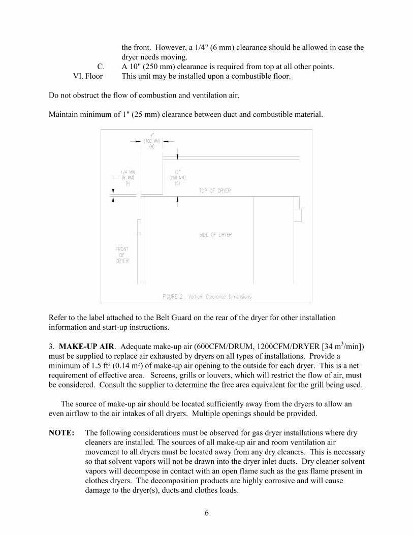
the front. However, a 1/4" (6 mm) clearance should be allowed in case the dryer needs moving.
C. A 10" (250 mm) clearance is required from top at all other points. VI. Floor This unit may be installed upon a combustible floor.
Do not obstruct the flow of combustion and ventilation air. Maintain minimum of 1" (25 mm) clearance between duct and combustible material.
Refer to the label attached to the Belt Guard on the rear of the dryer for other installation information and start-up instructions. 3. MAKE-UP AIR. Adequate make-up air (600CFM/DRUM, 1200CFM/DRYER [34 m3/min]) must be supplied to replace air exhausted by dryers on all types of installations. Provide a minimum of 1.5 ft² (0.14 m²) of make-up air opening to the outside for each dryer. This is a net requirement of effective area. Screens, grills or louvers, which will restrict the flow of air, must be considered. Consult the supplier to determine the free area equivalent for the grill being used.
The source of make-up air should be located sufficiently away from the dryers to allow an even airflow to the air intakes of all dryers. Multiple openings should be provided. NOTE: The following considerations must be observed for gas dryer installations where dry
cleaners are installed. The sources of all make-up air and room ventilation air movement to all dryers must be located away from any dry cleaners. This is necessary so that solvent vapors will not be drawn into the dryer inlet ducts. Dry cleaner solvent vapors will decompose in contact with an open flame such as the gas flame present in clothes dryers. The decomposition products are highly corrosive and will cause damage to the dryer(s), ducts and clothes loads.
7
4. ELECTRICAL REQUIREMENTS. (Refer to schematic and wiring diagram). This dryer is equipped with a control transformer for use on 208-240V-1PH-60Hz. The control voltage is 24V-60 Hz. The electrical power requirements necessary to operate the unit satisfactorily are listed on the serial plate located on the back panel of each dryer. The electrical connection should be made to the terminal in the control box on the rear of the unit, using #12 AWG for 208-240V (no neutral required).
It is absolutely necessary that the dryer be grounded to a known ground.
Individual circuit breakers for each stacked dryer are required. Use 15A or 20A circuit breakers for 208-240V.
5. GAS REQUIREMENTS. The complete gas requirements necessary to operate the dryer satisfactorily are listed on the serial plate located on the back panel of the dryer.
The inlet gas connection to the unit is 1/2-inch pipe thread. However, the size of the piping to supply the dryer should be determined by reference to the National Fuel Gas Code ANSI Z223.1A-1988 and consultation with the local gas supplier.
A joint compound resistant to the action of liquefied petroleum gases should be employed in making pipe connections.
A 1/8 inch NPT plugged tapping, accessible for test gage connection, must be installed immediately upstream of the gas supply connection to the dryer.
A drip tee is provided in the unit gas piping to catch dirt and other foreign articles.
All pipe connections should be checked for leakage with soap solution. Never check with an open flame.
For altitudes above 2,000 feet (610 m), it is necessary to derate the BTU input. Contact your local distributor for instructions.
L.P. gas conversion kits are available for this dryer. Contact your local distributor.
6. PRESSURE TESTING. The dryer and its individual shutoff valve must be disconnected from the gas supply piping system during any pressure testing of that system at test pressure in excess of 1/2 PSIG [35mbar]. The dryer must be isolated from the gas supply piping system by closing its individual manual shutoff valve during any pressure testing of the gas supply piping system at test pressures equal to or less than 1/2 PSIG (35 mbar). 7. EXHAUST INSTALLATION. (Refer to Figure 3 at the end of section 7.) Exhausting of the dryer(s) should be planned and constructed so that no air restrictions occur. Any restriction due to pipe size or type of installation can cause slow drying time, excessive heat, and lint in the room.
From an operational standpoint, incorrect or inadequate exhausting can cause a cycling of the high limit thermostat, which shuts off the main burners and results in inefficient drying.

8
The exhaust duct connection near the top of the dryer will accept an 8" (200 mm) round duct.
Individual exhausting of the dryers is recommended. A pipe of the proper diameter should be attached to the dryer adapter collar and extended out through an outside wall to exhaust all heat, moisture, and lint outside. This pipe must be very smooth on the inside, as rough surfaces tend to collect lint, which will eventually clog the duct and prevent the dryer from exhausting properly. All elbows must be smooth on the inside. All joints must be made so the exhaust end of one pipe is inside the next one downstream. The addition of an exhaust pipe tends to reduce the amount of air the blower can exhaust. This does not affect the dryer operation if held within practical limits. For the most efficient operation, it is recommended that no more than 14 ft (4.27 m) of straight 8” diameter pipe with two right angle elbows is used for each cylinder. When more than two elbows are used, two feet of straight pipe should be removed for each additional elbow. No more than four right angle elbows should be used to exhaust a dryer.
Maintain minimum 1" (25 mm) clearance between duct and combustible material.
If the exhaust pipe passes through a wall, a metal sleeve of slightly larger diameter should be set in the wall and the exhaust pipe passed through this sleeve. This practice is required by some local codes and is recommended in all cases to protect the wall. This type of installation should have a means provided to prevent rain and high winds from entering the exhaust when the dryer is not in use. A hood with a hinged damper can be used for this purpose. Another method would be to point the outlet end of the pipe downward to prevent entrance of wind and rain. In either case, the outlet should be kept clear, by at least 24" (610 mm), of any objects that would cause an air restriction.
Never install a protective screen over the exhaust outlet.
When exhausting a dryer straight up through a roof, the overall length of the duct has the same limits as exhausting through a wall. A rain cap must be placed on top of the exhaust and must be of such a type as to be free from clogging. The type using a cone shaped “roof” over the pipe is suitable for this application.
Exhausting the dryer into a chimney or under a building is not permitted under any
conditions. In both cases, there is a danger of lint build-up, which can be highly combustible. Installation of several dryers, where a main discharge duct is necessary, will need the
following considerations for installation (see Figure 3). Individual 8" ducts from the dryers into the main discharge duct should be at a 45-degree angle in the direction of discharge airflow.
NOTE: Never install the individual 8" ducts at a right angle into the main discharge duct. The individual ducts from the dryers can enter at the sides or bottom of the main discharge duct. Figure 3 indicates the various round main duct diameters to use with the individual dryer ducts. The main duct can be rectangular or round, provided adequate airflow is maintained. For each individual dryer, the total exhausting (main discharge duct plus duct outlet from the dryer) should not exceed the equivalent of 14 ft (4.27m) and two elbows. The diameter of the main discharge duct at the last dryer must be maintained to exhaust end.

9
NOTE: A small diameter duct will restrict airflow; a large diameter duct will reduce air velocity; both contributing to lint build up. An inspection door should be provided for periodic clean out of the main duct.
8. DRYER IGNITION (SOLID STATE IGNITION). The solid-state ignition system lights the main burner gas by spark. The gas is ignited and burns only when the gas-valve relay (in the electronic controller) calls for heat. The procedure for first-time starting of a dryer is as follows:
A. First, review and comply with the “Warnings About Use and Operation” found on the inside front cover of this manual. Be sure the electrical power supply is connected correctly. The dryer MUST be properly grounded.
B. Make sure all gas supply lines are purged of air, close the main gas shut-off valve and wait for five minutes before turning the valve back on.
C. Turn on main electrical power switch, close loading door, use manual mode to set the cycle time, and actuate the dryer by pushing the start button.
D. Natural gas and LPG fired dryers operate in the same manner. When the gas valve relay contacts are closed (indicating a demand for heat), the solid-state ignition control will automatically supply energy to the redundant gas valve. Sparking will continue until a flame is detected by the sensing probe, but not longer than ten seconds. If the gas fails to ignite in 10 seconds, the gas valve closes and the gas system pauses to allow gas to purge from the inside of the dryer. After the pause, the ignition control repeats the ignition trial cycle twice more. If the gas system fails to detect ignition after the three attempts, the system will "lock out". No further attempts will be performed automatically. To reset the ignition control, open the dryer door (stopping the dryer) for 15 seconds to interrupt electrical power to the ignition control. Closing the door and pushing the "Start" button will repeat the ignition trial cycle.
9. MAIN BURNER ADJUSTMENT. The primary air shutter of each main burner must be properly adjusted for the correct air-gas ratio. Loosen the shutter locking screw. Adjust the shutter by closing it sufficiently to give a blue flame with a yellow tip. Next open the shutter until the yellow tips are at a minimum. After adjustment securely lock each shutter in position by

10
tightening the shutter locking screws.
DRYER SHUTDOWN To render the dryer inoperative, turn off the main gas shut-off valve and disconnect power to the dryer.
11

12
DRYER CONTROLLER FACTORY DEFAULT PROGRAM SETTINGS
DRY CYCLE
COOL DOWN TIME (MINUTES)
TOTAL CYCLE TIME (MINUTES)
DRYING TEMPERATURE
(0F) (0C) DRYER LOAD
1 5 35 180 82 Towels, pads, heavy cotton 2 2 20 170 77 Sheets, blended materials 3 5 25 180 82 Cotton 4 2 20 130 54 Synthetic materials 5 2 25 175 79 Blended materials
DRYER FAULT CODES
FAULT# FAULT
DESCRIPTION ACTION
F1 Shorted thermostat
sensor.
Dryer stops and “F1” flashes on the 4-digit display. When short circuit on sensor input is removed, “LOAd” appears on
the 4-digit display and the remaining dry time is reset.
F2 Open thermostat
sensor.
Dryer stops and “F2” flashes on the 4-digit display. When a good sensor is connected to sensor input, “LOAd” appears on
the 4-digit display and the remaining dry time is reset.
F3 EEPROM corrupted.
Dryer will not start and “F3” appears on the 4-digit display. The power to the dryer must be cycled to reset the controller.
Fault should only occur when starting a dry cycle.
F4 Gas valve on fault.
The drying temperature did not increase 1ºF. in 15 minutes. “F4” will flash on the display and the dry cycle will finish
without calling for heat (energizing gas valve). Opening the door or pressing the STOP key will reset the fault and clear the
remaining time in the dry cycle.
F5 Temperature fault.
The drying temperature is at least 25ºF. above the temperature setting. “F5” will flash on the 4-digit display and the dry cycle will finish without calling for heat (energizing the gas valve). The power to the dryer must be cycled to reset the controller.
13
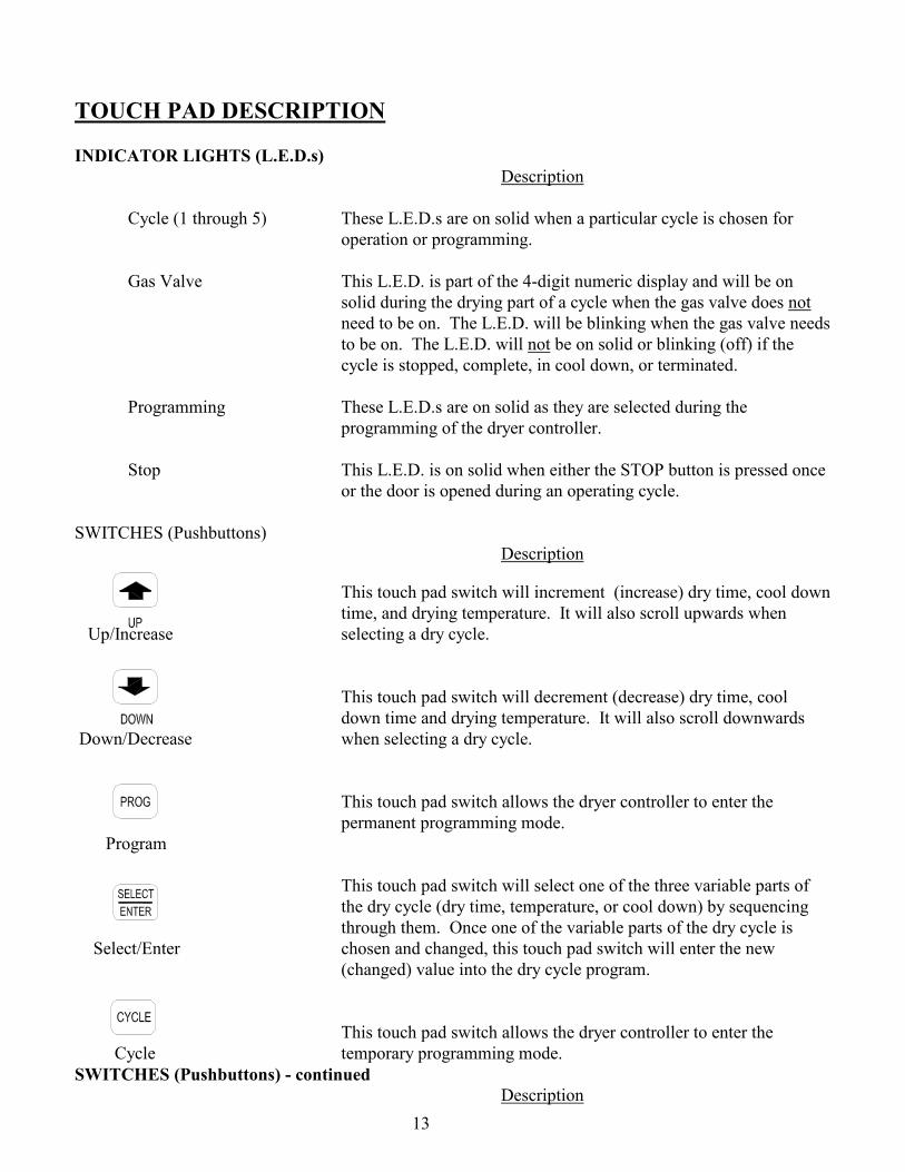
TOUCH PAD DESCRIPTION INDICATOR LIGHTS (L.E.D.s)
Description
Cycle (1 through 5) These L.E.D.s are on solid when a particular cycle is chosen for operation or programming.
Gas Valve This L.E.D. is part of the 4-digit numeric display and will be on
solid during the drying part of a cycle when the gas valve does not need to be on. The L.E.D. will be blinking when the gas valve needs to be on. The L.E.D. will not be on solid or blinking (off) if the cycle is stopped, complete, in cool down, or terminated.
Programming These L.E.D.s are on solid as they are selected during the
programming of the dryer controller. Stop This L.E.D. is on solid when either the STOP button is pressed once
or the door is opened during an operating cycle.
SWITCHES (Pushbuttons) Description
This touch pad switch will increment (increase) dry time, cool down time, and drying temperature. It will also scroll upwards when
Up/Increase selecting a dry cycle.
This touch pad switch will decrement (decrease) dry time, cool down time and drying temperature. It will also scroll downwards
Down/Decrease when selecting a dry cycle.
This touch pad switch allows the dryer controller to enter the permanent programming mode.
Program
This touch pad switch will select one of the three variable parts of the dry cycle (dry time, temperature, or cool down) by sequencing through them. Once one of the variable parts of the dry cycle is
Select/Enter chosen and changed, this touch pad switch will enter the new (changed) value into the dry cycle program.
This touch pad switch allows the dryer controller to enter the Cycle temporary programming mode. SWITCHES (Pushbuttons) - continued Description
14
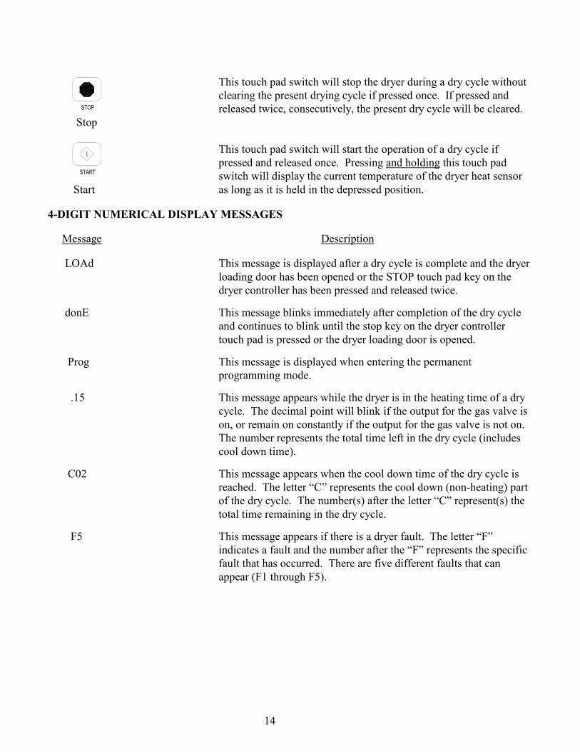
This touch pad switch will stop the dryer during a dry cycle without
clearing the present drying cycle if pressed once. If pressed and released twice, consecutively, the present dry cycle will be cleared.
Stop
This touch pad switch will start the operation of a dry cycle if
pressed and released once. Pressing and holding this touch pad switch will display the current temperature of the dryer heat sensor
Start as long as it is held in the depressed position.
4-DIGIT NUMERICAL DISPLAY MESSAGES
Message Description
LOAd This message is displayed after a dry cycle is complete and the dryer loading door has been opened or the STOP touch pad key on the dryer controller has been pressed and released twice.
donE This message blinks immediately after completion of the dry cycle and continues to blink until the stop key on the dryer controller touch pad is pressed or the dryer loading door is opened.
Prog This message is displayed when entering the permanent programming mode.
.15 This message appears while the dryer is in the heating time of a dry cycle. The decimal point will blink if the output for the gas valve is on, or remain on constantly if the output for the gas valve is not on. The number represents the total time left in the dry cycle (includes cool down time).
C02 This message appears when the cool down time of the dry cycle is reached. The letter “C” represents the cool down (non-heating) part of the dry cycle. The number(s) after the letter “C” represent(s) the total time remaining in the dry cycle.
F5 This message appears if there is a dryer fault. The letter “F” indicates a fault and the number after the “F” represents the specific fault that has occurred. There are five different faults that can appear (F1 through F5).

15
OPERATING INSTRUCTIONS To dry a load of items, you must choose one of the five-programmed dry cycles. Each of these five dry cycles may be modified in two different ways to match your load. Please refer to the “Permanent Dryer Controller Programming” or “Temporary Dryer Controller Programming” section of this manual. There are two parts to each dry cycle. The first part is the heating time, which is when the gas valve is cycled on and off according to the temperature setting in the dry cycle program. The second part is the cool down time, which is after the heating part of the dry cycle, and is when the cylinder continues to turn, but no heat is applied. There will always be at least two minutes of cool down time for each dry cycle. The maximum amount of cool down time is 60 minutes. The default value of the five dry cycles is shown in the “DRYER CONTROLLER FACTORY DEFAULT PROGRAM SETTINGS” table in this manual. To improve the drying capabilities of this dryer, you should always separate (untangle) the individual articles in your load before using the dryer. In the following instruction steps, things that are displayed on the 4-digit numerical display will be in “quotation marks” and any keys on the dryer controller touch pad that physically need to be pressed will be in CAPITAL AND BOLD LETTERS. 1) Place your untangled load into the dryer cylinder and close the dryer loading door. Notice that the
dryer controller 4-digit numerical display should show the word “LOAd”. If it does not show this word, then press and release the STOP touch pad key on the dryer controller twice.
2) Press and release the UP or DOWN arrow touch pad key on the dryer controller to select a dry cycle. 3) Once the desired dry cycle is selected, press and release the START touch pad key.
After the dryer controller START touch pad key is pressed, the dryer cylinder will start rotating and the two-digit total dry cycle time, along with a decimal point, will appear on the dryer controller display. The time shown on the dryer controller display will count down to the programmed cool down time. At that time, the display will change from the decimal point and two-digit number to a letter “C” and two digits. The letter “C” represents the cool down portion of the dry cycle. The two digits represent the amount of time remaining in the dry cycle. The two-digit time, shown on the dryer controller display, will count down to zero.
When the time decrements to zero, the dryer controller display will flash the word “donE” and the end of cycle tone will sound. At that point, the wrinkle free cycle will automatically begin. This cycle will wait two minutes, if the door is not opened or the STOP touch pad key on the dryer controller is not pressed, and then rotate the cylinder for 10 seconds and stop. This idle time of two minutes and tumble time of 10 seconds will repeat a total of 10 times, at which time the wrinkle free cycle stops. The cylinder will not rotate again until a new dry cycle is started.

16
During the wrinkle free cycle the gas valve will not be operated and there will be no heat applied to the load. The word “donE” will also continue to flash and do so even after the wrinkle free cycle is finished. When the dryer loading door is opened, or the STOP touch pad key is pressed, the word “donE” will change to the word “LOAd” on the dryer controller display. The dryer will then be ready for another dry cycle. During the dry cycle, either pressing the STOP touch pad key on the dryer controller or opening the dryer loading door, will stop the dry cycle and not clear it. If you press the STOP touch pad key on the controller and then open the dryer loading door the dry cycle will not be cleared. However, if you open (or open and close) the dryer loading door and then press the STOP touch pad key on the dryer controller, the present dry cycle will be cleared and the word “LOAd” will appear on the dryer controller display. There are two jumpers and one push button on the component side of the dryer controller printed circuit board. The jumper located at the back right side of the each circuit board controls whether the controller display shows and operates in the Fahrenheit or Celsius mode. This jumper is labeled as TEMP SELECT and has three pins. The back and middle pins are for Celsius and the front and middle pins are for Fahrenheit, which is indicated by the letter C for Celsius and the letter F for Fahrenheit. The other jumper, located at the back middle side of each circuit board controls, is used for choosing either a reversing or non-reversing type of dryer. This jumper is labeled as REV and NON-REV. This jumper must be in the non-reversing position, which are the front and middle pins. If the jumper is in the reversing position, the heating part of the dry cycle will not operate properly. The dryer will not reverse direction either. The push button, which is located at the middle center of each circuit board controls, is used to reset all five of the dry cycles to the factory default settings. It is labeled as DEFAULT SETTINGS. Even the dry cycles that have been modified using the permanent programming procedure will be changed back to the factory default settings when using this push button. This push button must be pressed and held for at least three seconds with power applied to the dryer controller circuit board. If changing a jumper, remove power before moving jumper and then move jumper. Before restoring power, press and hold the DEFAULT SETTINGS pushbutton. Then, restore power and release the DEFAULT SETTINGS pushbutton after three seconds of restoring power.

17
TEMPORARY DRYER CONTROLLER PROGRAMMING The temporary programming mode will allow the change of the stored dry cycle settings in the dryer controller for one complete dry cycle. After the dry cycle is complete, the default settings that existed before the temporary change are restored. The temporary dry cycle can be stopped and cleared at any time during the dry cycle operation. To temporarily change a dryer controller cycle, follow the procedures below. Things that are displayed on the 4-digit numeric display will be in “quotation marks”. Keys on the dryer controller touch pad that physically need to be pressed will be in CAPITAL AND BOLD LETTERS. If, at any time, you want to escape the temporary programming mode while changing the program settings, you can press the STOP key on the dryer controller touch pad if the 4-digit numeric display is not flashing. The SELECT/ENTER key on the dryer controller touch pad can be pressed and released to enter the flashing value shown on the 4-digit numeric display and allow you to escape. If you press and release the STOP key on the dryer controller touch pad, when the 4-digit numeric display is not flashing, the temporary changes to the dry cycle program will be cancelled. The stored dry cycle settings that existed before the temporary change will then be restored. If, at any time, you want to start the temporary dry cycle during the temporary programming mode, press and release the START key on the dryer controller touch pad if the 4-digit numeric display is not flashing. The SELECT/ENTER key on the dryer controller touch pad can be pressed and released to enter the flashing value shown on the 4-digit numeric display and allow you to start the temporary dry cycle. If you start the temporary dry cycle, the 4-digit numerical display will change to the total dry time and count down to 0 as the dry cycle progresses.
PROCEDURE 1) Make sure the dryer is not in a dry cycle. The 4-digit numeric display on the dryer controller will
show “LOAd” when the dryer is not in a dry cycle. 2) Press and release the UP or DOWN arrow keys on the dryer controller touch pad to chose the dry
cycle that you want to change (dry cycle 1 through 5). The dry cycle L.E.D. will illuminate to indicate which dry cycle you are choosing. If you press either arrow key and hold it down, the controller will sequence through the five dry cycles.
3) Press and release the CYCLE key on the dryer controller touch pad once you have chosen the dry
cycle you want to change. After you press this key, the programming L.E.D. and the dry time L.E.D. will illuminate. The dry cycle L.E.D. will remain illuminated. The total dry time will also be displayed on the 4-digit numeric display.
4) Press and release the UP or DOWN arrow keys to change the total cycle time. Once either of the
arrow keys is pressed, the dry time L.E.D. and the total dry time on the 4-digit numeric display will flash. If you press and hold either arrow key down, you will increment (UP arrow) or decrement (DOWN arrow) through the total dry times available (1 through 60 minutes). This displayed dry time includes the cool down time along with the heated time. To not change the total dry time, do not press the arrow keys to change the total dry time.
5) Press and release the SELECT/ENTER key. Once this key is pressed and released, the dry time L.E.D. will switch off, the dry cycle L.E.D. and programming L.E.D. will remain on, and the temperature L.E.D. will illuminate. The drying temperature will also be shown on the 4-digit numeric

18
display. 6) Press and release the UP or DOWN arrow keys to change the drying temperature. Each press and
release of the arrow keys will either increase or decrease the temperature by five degrees Fahrenheit or three degrees Celsius, depending on how your dryer controller is set up. Once either of the arrow keys is pressed, the temperature L.E.D. and the drying temperature on the 4-digit numeric display will flash. If you press and hold either arrow key down, you will increment (UP arrow) or decrement (DOWN arrow) your way through the available drying temperatures (105º Fahrenheit or 40º Celsius, up to 195º Fahrenheit or 91º Celsius). If you do not want to change the drying temperature, do not press the arrow keys. Go to the next step.
7) Press and release the SELECT/ENTER key. Once this key is pressed and released, the temperature
L.E.D. will switch off, the dry cycle L.E.D. and programming L.E.D. will remain on, and the cool down L.E.D. will illuminate. The cool down time will also be shown on the 4-digit numeric display.
8) Press and release the UP or DOWN arrow keys to change the cool down time. Once either of the
arrow keys is pressed, the cool down L.E.D. and the cool down time on the 4-digit numeric display will flash. If you press and hold either arrow key down, you will increment (UP arrow) or decrement (DOWN arrow) through the cool down times available (2 through 60 minutes). To not change the cool down time, do not press the arrow keys. Go to the next step.
9) Press and release the SELECT/ENTER key. Once this key is pressed and released, the cool down
L.E.D. and the programming L.E.D. will switch off, and the dry cycle L.E.D. will remain on. The flashing cool down time on the 4-digit display will stop flashing and remain.
10) At this point, you have two choices. 1) You can perform the modified dry cycle by pressing and
releasing the START key on the dryer controller touch pad, or 2) You can clear the modified dry cycle program by pressing and releasing the STOP key once. If you start the modified cycle, the total dry time will appear on the 4-digit numeric display and it will count down to 0 as the dry cycle progresses. If you choose to clear the modified dry cycle, the 4-digit numeric display will change to “LOAd”.
TEMPORARY DRYER CONTROLLER PROGRAMMING EXAMPLE REQUIREMENTS: Dry a load with 40 minutes of actual heat at 185ºF and five minutes of cool down. The following procedure will show you how to temporarily modify the existing dry cycle 1 program for one cycle of drying. It is based on the assumption that the factory defaults have not been permanently changed. If they have been changed, the steps of this procedure will be the same, but the values that are displayed will be different. The amount of times that the dryer controller touch pad UP or DOWN keys must be pressed and released may also be different. If you want the change to be permanent, go to the “PERMANENT DRYER CONTROLLER PROGRAMMING” section of this manual.
PROCEDURE 1) After the load has been placed in the dryer, press and release the UP or DOWN touch pad key on the

19
dryer controller until the L.E.D. for dry cycle 1 is illuminated. 2) Press and release the CYCLE key on the dryer controller touch pad. You will see the number “35” on
the dryer controller display. The programming L.E.D. and dry time L.E.D. will be illuminated. 3) Press and release the UP arrow key on the dryer controller touch pad 10 times so the display will show
a flashing “45”. When the UP arrow touch pad key is pressed the first time, the number “36” will be flashing on the dryer controller display. Each number after that will also flash.
4) Now, press and release the SELECT/ENTER touch pad key on the dryer controller. The number
“45” will stop flashing and the dry time L.E.D. will switch off. The dryer controller display will now show “180”, the temperature L.E.D. will illuminate, and the programming L.E.D. and dry cycle 1 L.E.D. will remain on.
5) Press and release the UP arrow key on the dryer controller touch pad one time so the controller display
will show a flashing “185”. Each press of the UP arrow key will increment the temperature by five degrees.
6) Now, press and release the SELECT/ENTER touch pad key on the dryer controller. The number
“185” will stop flashing and the temperature L.E.D. will switch off. The dryer control display will now show a number “5”, the cool down L.E.D. will illuminate, and the programming L.E.D. and dry cycle 1 L.E.D. will remain on.
7) Press and release the SELECT/ENTER key on the dryer controller touch pad, since the desired cool
down time is five minutes. After you press the SELECT/ENTER touch pad key on the controller, the cool down L.E.D. and programming L.E.D. will switch off. The controller display will remain at “5” and the cycle 1 L.E.D. will remain on.
You are now ready to start the new dry cycle. This new dry cycle will be in effect for one dry cycle only. After the dry cycle is done, or if the STOP touch pad key on the dryer controller is pressed and released twice, consecutively, the cycle 1 program will revert to the factory default settings.
If you press the START touch pad key on the dryer controller, the controller display will change from the number “5” to the number “45” and dry cycle 1 will begin.

20
PERMANENT DRYER CONTROLLER PROGRAMMING The permanent programming mode will allow the change of the stored dry cycle settings in the dryer controller until the operator physically changes them again. The factory default settings can be restored in the dryer controller by pressing the default settings pushbutton on the back (component) side of the dryer controller circuit board. It is labeled and located at the lower middle side of the printed circuit board, as you face the component side of the board. It must be pressed and held down for at least three seconds. To permanently change a dryer controller cycle, follow the procedure below. Things that are displayed on the 4-digit numeric display will be in “quotation marks”. Keys on the touch pad that physically need to be pressed will be in CAPITAL AND BOLD LETTERS. If, at any time, you want to escape the permanent programming mode while changing the settings, you can press the STOP key on the dryer controller touch pad if the 4-digit numeric display is not flashing. The SELECT/ENTER key on the dryer controller touch pad can be pressed and released to enter the flashing value shown on the 4-digit numeric display and allow you to escape.
PROCEDURE 1) Make sure the dryer is not in a dry cycle. The 4-digit numeric display on the dryer controller will
show “LOAd” when the dryer is not in a dry cycle. 2) Press and release the PROG key on the dryer controller touch pad. 3) Press and release the UP arrow key on the dryer controller touch pad. The programming L.E.D. will
illuminate and the 4-digit numeric display on the dryer controller will change to “Prog”.
4) Press and release the UP or DOWN arrow keys to choose the dry cycle you want to change (dry cycle 1 through 5). The dry cycle L.E.D. will illuminate to indicate which dry cycle you are choosing. If you press either arrow key and hold it down, the controller will sequence through the five dry cycles.
5) Press and release the SELECT/ENTER key once you have chosen the dry cycle you want to change. After you press this key, the dry time L.E.D. will illuminate. The dry cycle L.E.D. and the programming L.E.D. will remain illuminated. The total dry time will also be displayed on the 4-digit numeric display.
6) Press and release the UP or DOWN arrow keys to change the total dry time. Once either of the arrow keys is pressed, the dry time L.E.D. and the total dry time on the 4-digit numeric display will flash. If you press and hold either arrow key down, you will increment (UP arrow) or decrement (DOWN arrow) through the total dry times available (1 through 60 minutes). This displayed dry time includes the cool down time along with the heated time. To not change the total dry time, do not press the arrow keys. Go to the next step.
7) Press and release the SELECT/ENTER key. Once this key is pressed and released, the dry time L.E.D. will switch off, the dry cycle L.E.D. and programming L.E.D. will remain on, and the temperature L.E.D. will illuminate. The drying temperature will also be shown on the 4-digit numeric display.
8) Press and release the UP or DOWN arrow keys to change the drying temperature. Each press and release of the arrow keys will either increase or decrease the temperature by five degrees Fahrenheit or three degrees Celsius, depending on how your dryer controller is set up. Once either of the arrow keys
21
is pressed, the temperature L.E.D. and the drying temperature on the 4-digit numeric display will flash. If you press and hold either arrow key down, you will increment (UP arrow) or decrement (DOWN arrow) your way through the available drying temperatures (105º Fahrenheit or 40º Celsius, up to 195º Fahrenheit or 91º Celsius). If you do not want to change the drying temperature, do not press the arrow keys. Go to the next step.
9) Press and release the SELECT/ENTER key. Once this key is pressed and released, the temperature
L.E.D. will switch off, the dry cycle L.E.D. and programming L.E.D. will remain on, and the cool down L.E.D. will illuminate. The cool down time will also be shown on the 4-digit numeric display.
10) Press and release the UP or DOWN arrow keys to change the cool down time. Once either of the
arrow keys is pressed, the cool down L.E.D. and the cool down time on the 4-digit numeric display will flash. If you press and hold either arrow key down, you will increment (UP arrow) or decrement (DOWN arrow) through the cool down times available (2 through 60 minutes). To not change the cool down time, do not press the arrow keys. Go to the next step.
11) Press and release the SELECT/ENTER key. Once this key is pressed and released, the cool down
L.E.D. will switch off, the dry cycle L.E.D. and programming L.E.D. will remain on, and the 4-digit numeric display will change to “Prog”.
12) Press and release the STOP key to save the cycle program and escape the programming mode. If you
want to change the same dry cycle program again, press the SELECT/ENTER key and continue at step 6 of this procedure. If you want to modify another dry cycle program, go to step 4 of this procedure and continue.
13) If you pressed the STOP key to escape the programming mode, you may now start the dry cycle by
pressing the START key.
PERMANENT DRYER CONTROLLER PROGRAMMING EXAMPLE REQUIREMENTS: Dry a load with 50 minutes of actual heat at 195º F and three minutes of cool down. The following procedure will show you how to permanently modify the existing dry cycle 1 program for one cycle of drying. It is based on the assumption that the factory defaults have not been permanently changed. If they have been changed, the steps of this procedure will be the same, but the values that are displayed will be different. The amount of times that the dryer controller touch pad UP or DOWN keys must be pressed and released may also be different. If you want the change to be temporary (for only one dry cycle), go to the “TEMPORARY DRYER CONTROLLER PROGRAMMING” section of this manual.
PROCEDURE
1) After the load has been placed in the dryer, press and release the UP or DOWN touch pad key on the
dryer controller until the L.E.D. for dry cycle 1 is illuminated.

22
2) Press and release the PROG touch pad key on the dryer controller. The dryer controller display will not change.
3) Immediately, press and release the UP arrow key on the dryer controller touch pad. The controller display will change from “LOAd” to “Prog”. You have now entered the permanent programming mode. The dry time L.E.D. will remain on and the programming L.E.D. will illuminate.
4) Press and release the SELECT/ENTER touch pad key once. The dry time L.E.D. and programming
L.E.D. will remain on and the dry time L.E.D. will illuminate. The dryer controller will also show the number “35”.
5) Press the UP arrow touch pad key 18 times until the dryer controller display shows the number “53”. 6) Press and release the SELECT/ENTER touch pad key once. The dry time L.E.D. and programming
L.E.D. will remain on and the dry time L.E.D. will switch off. The temperature L.E.D. will illuminate and the dryer controller display will show the number “180”.
7) Press and release the UP arrow touch pad key three times until the dryer controller display shows the
number “195”. 8) Press and release the SELECT/ENTER touch pad key. The dry time L.E.D. and the programming
L.E.D. will remain on and the temperature L.E.D. will switch off. The cool down L.E.D. will illuminate and the dryer controller display will show the number “5”.
9) Press and release the DOWN arrow touch pad key twice until the dryer controller display shows the
number “3”. 10) Press and release the SELECT/ENTER touch pad key. The dry time L.E.D. and the programming
L.E.D. will remain on and the cool down L.E.D. will switch off. The dryer controller display will change to “Prog”.
11) Press and release the STOP touch pad key. The dry time L.E.D. will remain on and the programming L.E.D. will switch off. The dryer controller display will change to the word “LOAd”.
The dryer is now ready for the new modified dry cycle to start. This modified dry cycle 1 program will remain in the dryer controller memory until the default settings push button is pressed. This default settings push button is located on the component side of the dryer controller printed circuit board at the middle center side of each circuit board controls.
23
SERVICING THE DRYER CAUTION: Label all wires prior to disconnection when servicing controls. Wiring errors can cause improper and dangerous operation. Verify proper operation after servicing. ATTENTION: Lors des opérations d'entretien des commandes, étiqueter tous les fils avant de les déconnecter. Touteerreur de câblage peut être une source de danger et de panne.
DRYER PREVENTIVE MAINTENANCE (PM) REQUIREMENTS MAKE SURE ALL POWER IS DISCONNECTED BEFORE SERVICING
MACHINE DAILY 1. Clean lint screen using a soft brush if necessary. Check lint screen for rips or tears and replace if
damaged. MONTHLY 1. Clean lint from motor end bells and dryer controls area. 2. Clean lint from lint screen compartment. 3. Clean lint accumulation from top and all areas above, around and below burners and burner
housing. Failure to keep this section of dryer free from lint can create a fire hazard. SEMI-ANNUALLY 1. Check V-belts for cracks, wear, fraying, or looseness. 2. Inspect all fasteners (screws, bolts, nuts, etc.) and tighten any that are loose. 3. Clean all lint accumulation from inside of front panel. 4. Place a few drops of light oil on top and bottom pivots of the door hinge. 5. Inspect door glass gasket for excessive wear. 6. Clean lint accumulation from the burner primary air ports. 7. Check intermediate drive pulley bushings for excessive wear. ANNUALLY 1. Remove, inspect and clean main burner orifices of obstructions or dirt. 2. Grease intermediate drive pulley bearing at zerk grease fitting. 3. Inspect and remove any lint accumulation in the exhaust ducts. Inspect all ducting from the
dryer exhaust connection to the exit wall or roof. 4. Check tumbler shaft retaining nut for 125 lb-ft torque.
Contact Information: Address: Dexter Laundry Inc., 2211 W. Grimes Ave., Fairfield, IA 52556 Phone: 1-641-472-5131 Website: www.dexterlaundry.com

24
Maintenance Notes: