OPERATOR'S MANUAL - Fondriest Environmental, Inc. · • This manual has been authored with...
125
FACSIMILE RECEIVER FAX-30 OPERATOR'S MANUAL www.furuno.com Model
Transcript of OPERATOR'S MANUAL - Fondriest Environmental, Inc. · • This manual has been authored with...

FACSIMILE RECEIVER
FAX-30
OPERATOR'S MANUAL
www.furuno.com
Model

FURUNO Authorized Distributor/Dealer
Printed in Japan
(Elemental Chlorine Free)
The paper used in this manual is elemental chlorine free.
9-52, Ashihara-cho,Nishinomiya, 662-8580, JAPAN
All rights reserved.
Pub. No. OME-62600-H(AKMU) FAX-30
A: SEP. 2002H: JUL. 25, 2013
00080937514

i
Ni-Cd Pb
IMPORTANT NOTICES General • This manual has been authored with simplified grammar, to meet the needs of
international users. • The operator of this equipment must read and follow the descriptions in this manual.
Wrong operation or maintenance can cancel the warranty or cause injury. • Do not copy any part of this manual without written permission from FURUNO. • If this manual is lost or worn, contact your dealer about replacement. • The contents of this manual and equipment specifications can change without notice. • The example screens (or illustrations) shown in this manual can be different from the
screens you see on your display. The screens you see depend on your system configuration and equipment settings.
• Save this manual for future reference. • Any modification of the equipment (including software) by persons not authorized by
FURUNO will cancel the warranty. • All brand and product names are trademarks, registered trademarks or service marks of
their respective holders. • Windows Vista, Internet Explorer and Windows are either registered trademarks or
trademarks of Microsoft Corporation in the United States and/or other countries.
How to discard this product Discard this product according to local regulations for the disposal of industrial waste. For disposal in the USA, see the homepage of the Electronics Industries Alliance (http://www.eiae.org/) for the correct method of disposal. How to discard a used battery Some FURUNO products have a battery(ies). To see if your product has a battery, see the chapter on Maintenance. Follow the instructions below if a battery is used. Tape the + and - terminals of battery before disposal to prevent fire, heat generation caused by short circuit. In the European Union The crossed-out trash can symbol indicates that all types of batteries must not be discarded in standard trash, or at a trash site. Take the used batteries to a battery collection site according to your national legislation and the Batteries Directive 2006/66/EU. In the USA The Mobius loop symbol (three chasing arrows) indicates that Ni-Cd and lead-acid rechargeable batteries must be recycled. Take the used batteries to a battery collection site according to local laws. In the other countries There are no international standards for the battery recycle symbol. The number of symbols can increase when the other countries make their own recycling symbols in the future.
Cd
ii
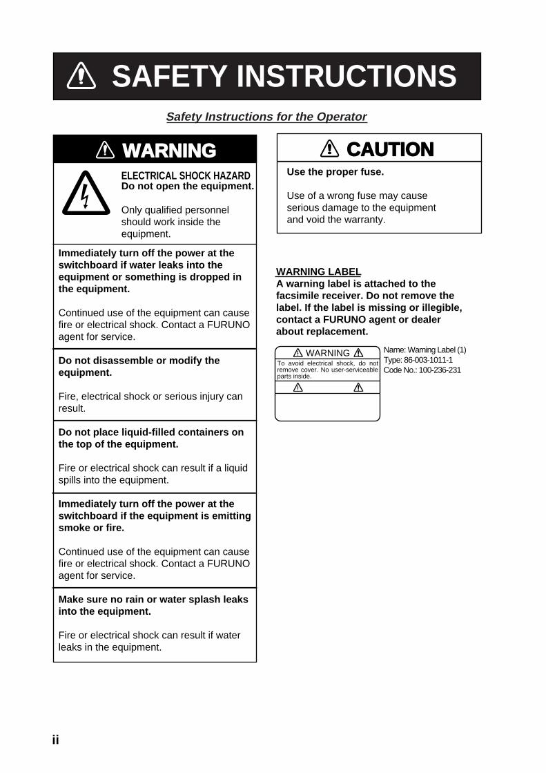
SAFETY INSTRUCTIONSSafety Instructions for the Operator
WARNING
Immediately turn off the power at theswitchboard if water leaks into theequipment or something is dropped inthe equipment.
Continued use of the equipment can causefire or electrical shock. Contact a FURUNOagent for service.
Do not disassemble or modify theequipment.
Fire, electrical shock or serious injury canresult.
Do not place liquid-filled containers onthe top of the equipment.
Fire or electrical shock can result if a liquidspills into the equipment.
Immediately turn off the power at theswitchboard if the equipment is emittingsmoke or fire.
Continued use of the equipment can causefire or electrical shock. Contact a FURUNOagent for service.
Make sure no rain or water splash leaksinto the equipment.
Fire or electrical shock can result if waterleaks in the equipment.
ELECTRICAL SHOCK HAZARDDo not open the equipment.
Only qualified personnelshould work inside theequipment.
WARNING LABELA warning label is attached to the facsimile receiver. Do not remove thelabel. If the label is missing or illegible,contact a FURUNO agent or dealerabout replacement.
WARNINGTo avoid electrical shock, do not remove cover. No user-serviceable parts inside.
Name: Warning Label (1)Type: 86-003-1011-1Code No.: 100-236-231
Use the proper fuse.
Use of a wrong fuse may cause serious damage to the equipmentand void the warranty.
CAUTION

iii
WARNING
Turn off the power at the switchboardbefore beginning the installation.
Fire or electrical shock can result if thepower is left on.
Do not install the equipment where itmay get wet from rain or water splash.
Water in the equipment can result in fire,electrical shock or damage the equipment.
Be sure that the power supply iscompatible with the voltage rating ofthe equipment.
Connection of an incorrect power supplycan cause fire or damage the equipment.
ELECTRICAL SHOCK HAZARDDo not open the equipmentunless totally familiar withelectrical circuits andservice manual.
Only qualified personnelshould work inside theequipment.
Observe the following compass safedistances to prevent interference to amagnetic compass:
FacsimileReceiver
Standard Steeringcompass compass
0.9 m 0.6 m
Safety Instructions for the Installer
CAUTION

iv
TABLE OF CONTENTS FOREWORD .................................................................................................................vii SYSTEM CONFIGURATION ...........................................................................................x EQUIPMENT LISTS ......................................................................................................xii
1. OVERVIEW, SETUP ................................................................................................ 1-1 1.1 Setup: NavNet and NavNet vx2 .............................................................................................. 1-1
1.1.1 Controls ......................................................................................................................... 1-1 1.1.2 Preparations for using the FAX-30................................................................................ 1-2 1.1.3 Accessing the FAX mode.............................................................................................. 1-3 1.1.4 Choosing the receive mode .......................................................................................... 1-4 1.1.5 Receive notification ....................................................................................................... 1-5
1.2 Setup: PC ................................................................................................................................ 1-6 1.2.1 Accessing the FAX-30 top display ................................................................................ 1-6 1.2.2 Choosing the receive mode .......................................................................................... 1-8 1.2.3 Logging out.................................................................................................................... 1-8
1.3 Setup: NavNet 3D.................................................................................................................... 1-9 1.3.1 Controls ......................................................................................................................... 1-9 1.3.2 How to use FAX-30 with NavNet 3D........................................................................... 1-10 1.3.3 Receive mode ............................................................................................................. 1-12 1.3.4 Logout.......................................................................................................................... 1-12
2. FAX OPERATION: NavNet and NavNet vx2 .......................................................... 2-1 2.1 Automatic Receiving................................................................................................................ 2-1
2.1.1 Choosing channel.......................................................................................................... 2-1 2.1.2 Previewing image being received ................................................................................. 2-4 2.1.3 Stopping automatic receiving ........................................................................................ 2-4
2.2 Manually Starting, Stopping Receiving.................................................................................... 2-5 2.2.1 Manually starting receiving............................................................................................ 2-5 2.2.2 Manually stopping receiving.......................................................................................... 2-6
2.3 Timer Receiving....................................................................................................................... 2-7 2.3.1 Setting timer receiving schedule ................................................................................... 2-7 2.3.2 Turning on/off specific timer programs.........................................................................2-11 2.3.3 Clearing all timer programs..........................................................................................2-11
2.4 Displaying Facsimile Images................................................................................................. 2-12 2.5 Processing Facsimile Images................................................................................................ 2-13
2.5.1 Phase mismatch.......................................................................................................... 2-13 2.5.2 Phasing signal out of synchronization ........................................................................ 2-13 2.5.3 Noise rejection............................................................................................................. 2-14 2.5.4 Image color.................................................................................................................. 2-15 2.5.5 Image format ............................................................................................................... 2-15 2.5.6 Zooming images.......................................................................................................... 2-16 2.5.7 Rotating images .......................................................................................................... 2-16
2.6 Erasing Facsimile Images ..................................................................................................... 2-16 2.7 Preventing Erasure of Facsimile Images .............................................................................. 2-17 2.8 Adding Facsimile Channels................................................................................................... 2-18

v
3. FAX OPERATION: NavNet 3D, PC ..........................................................................3-1 3.1 Automatic Receiving................................................................................................................ 3-1
3.1.1 Starting receiving........................................................................................................... 3-1 3.1.2 Stopping receiving......................................................................................................... 3-1
3.2 Timer Receiving....................................................................................................................... 3-2 3.2.1 Setting, changing timer receiving schedule .................................................................. 3-2 3.2.3 Turning on/off specific timer programs.......................................................................... 3-4 3.2.4 Clearing all timer programs........................................................................................... 3-4
3.3 Displaying Facsimile Images................................................................................................... 3-5 3.4 Processing Facsimile Images.................................................................................................. 3-6
3.4.1 Phase mismatch............................................................................................................ 3-6 3.4.2 Phasing signal out of synchronization........................................................................... 3-7 3.4.3 Noise rejection............................................................................................................... 3-7 3.4.4 Image color.................................................................................................................... 3-8 3.4.5 Image format ................................................................................................................. 3-8 3.4.6 Rotating images ............................................................................................................ 3-9 3.4.7 Zooming images............................................................................................................ 3-9 3.4.8 Saving images............................................................................................................... 3-9
3.5 Erasing Facsimile Images ....................................................................................................... 3-9 3.6 Preventing Erasure of Facsimile Images .............................................................................. 3-10 3.7 Adding Facsimile Channels....................................................................................................3-11
4. NAVTEX OPERATION: NavNet and NavNet vx2 ...................................................4-1 4.1 About Navtex Messages.......................................................................................................... 4-1
4.1.1 Message categories ...................................................................................................... 4-1 4.1.2 Receiving navtex messages ......................................................................................... 4-1
4.2 Setting Up Navtex Stations, Messages, Alarms ..................................................................... 4-2 4.3 Previewing Incoming Navtex Messages ................................................................................. 4-5 4.4 Displaying Navtex Messages .................................................................................................. 4-6
4.4.1 Displaying navtex messages......................................................................................... 4-6 4.4.2 Remarks on navtex messages...................................................................................... 4-7
4.5 Displaying the Navtex Station List ........................................................................................... 4-8 4.6 Adding Navtex Stations ........................................................................................................... 4-9
5. NAVTEX OPERATION: NavNet 3D, PC...................................................................5-1 5.1 About Navtex Messages.......................................................................................................... 5-1
5.1.1 Message categories ...................................................................................................... 5-1 5.1.2 Receiving navtex messages ......................................................................................... 5-1
5.2 Setting Up Navtex Stations, Messages................................................................................... 5-2 5.3 Displaying Navtex Messages .................................................................................................. 5-3 5.4 Displaying the Navtex Station List ........................................................................................... 5-4 5.5 Adding Navtex Stations ........................................................................................................... 5-5 5.6 Editing Navtex Stations............................................................................................................ 5-6 5.7 Deleting Navtex Stations ......................................................................................................... 5-7
6. MAINTENANCE, TROUBLESHOOTING .................................................................6-1 6.1 Maintenance ............................................................................................................................ 6-1 6.2 Replacement of Fuse .............................................................................................................. 6-2 6.3 Troubleshooting ....................................................................................................................... 6-2

vi
6.4 Diagnostics .............................................................................................................................. 6-3 6.4.1 NavNet........................................................................................................................... 6-3 6.4.2 NavNet 3D, PC.............................................................................................................. 6-4
6.5 Clearing Data........................................................................................................................... 6-5 6.5.1 NavNet........................................................................................................................... 6-5 6.5.2 NavNet 3D, PC.............................................................................................................. 6-6
6.6 All Clear (for technicians) ........................................................................................................ 6-7 6.7 Simulation Mode...................................................................................................................... 6-8
6.7.1 NavNet........................................................................................................................... 6-8 6.7.2 Navnet 3D, PC .............................................................................................................. 6-9
7. INSTALLATION........................................................................................................ 7-1 7.1 Facsimile Receiver .................................................................................................................. 7-1 7.2 Antenna Unit ............................................................................................................................ 7-2
7.2.1 General antenna connection......................................................................................... 7-2 7.2.2 Wire antenna or whip antenna ...................................................................................... 7-2 7.2.3 Installation of preamp unit FAX-5 (option) .................................................................... 7-3
7.3 Wiring....................................................................................................................................... 7-4 7.4 Supplying Power to the Preamp Unit ...................................................................................... 7-6 7.5 Browser, PC Settings............................................................................................................... 7-7
7.5.1 Browser settings............................................................................................................ 7-7 7.5.2 PC settings .................................................................................................................... 7-8
APPENDIX ............................................................................................................... AP-1 Facsimile Stations........................................................................................................................ AP-1 Navtex Stations............................................................................................................................ AP-4 Menu Tree ................................................................................................................................... AP-9
SPECIFICATIONS.....................................................................................................SP-1
PACKING LIST............................................................................................................A-1 OUTLINE DRAWINGS ................................................................................................D-1 INTERCONNECTION DIAGRAM................................................................................ S-1
INDEX......................................................................................................................... IN-1

vii
FOREWORD
A Word to the Owner of the FAX-30 FURUNO Electric Company thanks you for purchasing the FURUNO FAX-30 Facsimile Receiver. We are confident you will discover why the FURUNO name has become synonymous with quality and reliability. Since 1948, FURUNO Electric Company has enjoyed an enviable reputation for quality and reliability throughout the world. This dedication to excellence is furthered by our extensive global network of agents and dealers. Your equipment is designed and constructed to meet the rigorous demands of the marine environment. However, no machine can perform its intended function unless properly installed and maintained. Please carefully read and follow the operation, installation and maintenance procedures set forth in this manual. We would appreciate feedback from you, the end-user, about whether we are achieving our purposes. Thank you for considering and purchasing FURUNO.
Features Connected to a NavNet series display unit (MODEL 1833C/1943C, MFDBB, MFD8/MFD12) or a PC, the FAX-30 receives facsimile images and navtex messages, transmitted from facsimile and navtex stations.
• Programmed with all existing facsimile stations and frequencies. User may program 320 channels.
• Fully automatic facsimile operation with built-in schedule timer. Storage for 30 timer programs.
• Fully automatic selection of speed, IOC, phase alignment and frequency. Manual selection also available.
• Connection to printer via a PC to print facsimile images and navtex messages.
• Facsimile images in monochrome, gray scale (8 tones) or color (three patterns).
• Built in navtex receiver. (The receiver does not conform to GMDSS regulations.)

viii
Operational Characteristics General
• The equipment receives one facsimile image or naxtex message at a time. Thus, a navtex message cannot be received when a facsimile image is being received and vice versa, regardless of navtex message category.
• Three receiving modes are available, facsimile, navtex, and facsimile(timer) & navtex. When using the facsimile(timer) and navtex, the order of priority is
Facsimile(timer) (highest priority) → Navtex (lowest priority)
• The FAX-30 does not have an internal clock, so time is input from a NavNet display or the PC. (For a PC-only configuration, time data is read when the browser accesses the FAX-30. Therefore, turn on the FAX-30 before accessing it from the PC to allow for input of time data, which is necessary for facsimile timer recording.) To receive time data, do the following:
NavNet: Output the date and time data sentence ZDA through the NavNet network. PC: Set the PC’s clock to the correct time.
• If both a NavNet series unit and a PC are used, it is recommended to operate the FAX-30 from the PC because of the two different communication protocols. (Use the NavNet series unit to feed navigation data to the PC.)
• Navigation data must be fed through the network to use the automatic navtex mode. Therefore, this mode is not available in the PC-only configuration.
NavNet
• The FAX-30 cannot be accessed from the NavNet for 15 seconds after the FAX-30 has been turned on.
• NavNet requirements: Navionics: Ver. 15, Boot Ver. 2 (1950006002) C-MAP by Jeppesen: Ver. 11, Boot Ver. 2 (1950006002)
NavNet 3D
The FAX-30 cannot be accessed when it is starting up, because image data is being loaded. You can access the FAX-30 when the LED flashes 0.4 seconds every 2 seconds, which starts approximately two minutes after the power is turned on.
PC
• The FAX-30 cannot be accessed from the PC while the FAX-30 is loading data at start up. Wait until the POWER LED flashing interval changes from 0.4 to two seconds before accessing the FAX-30.
• Most operating procedures in this manual are written for use with the Internet Explorer®. Menu items, control button names, etc. may be different on the Netscape Navigator.
ix
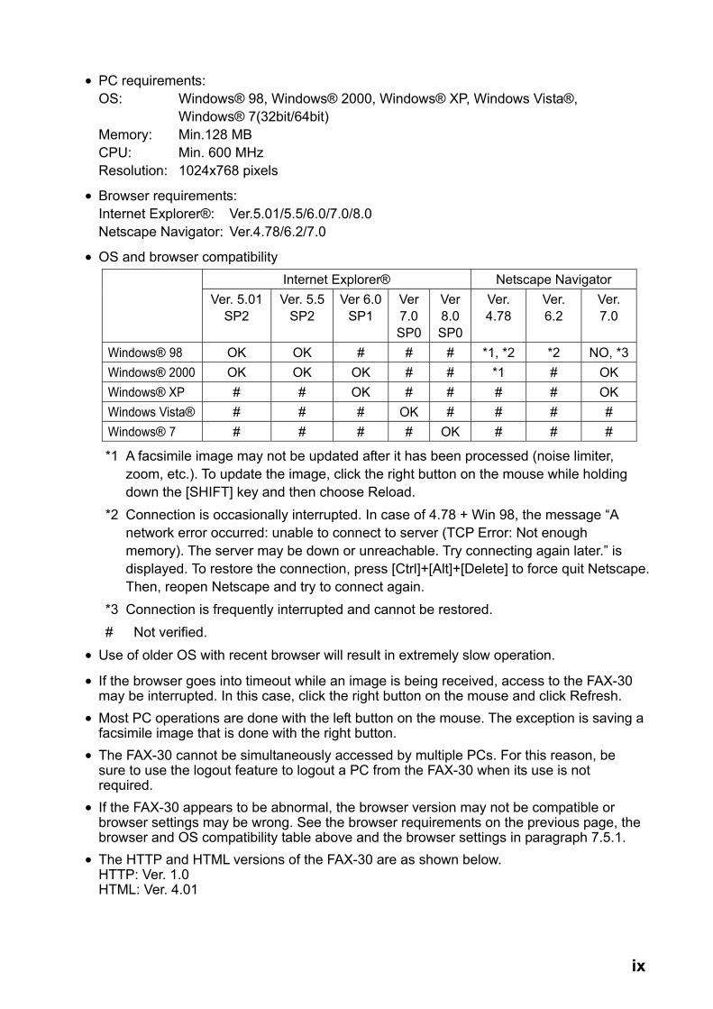
• PC requirements: OS: Windows® 98, Windows® 2000, Windows® XP, Windows Vista®, Windows® 7(32bit/64bit) Memory: Min.128 MB CPU: Min. 600 MHz Resolution: 1024x768 pixels
• Browser requirements: Internet Explorer®: Ver.5.01/5.5/6.0/7.0/8.0 Netscape Navigator: Ver.4.78/6.2/7.0
• OS and browser compatibility Internet Explorer® Netscape Navigator
Ver. 5.01 SP2
Ver. 5.5SP2
Ver 6.0 SP1
Ver 7.0 SP0
Ver 8.0 SP0
Ver. 4.78
Ver. 6.2
Ver. 7.0
Windows® 98 OK OK # # # *1, *2 *2 NO, *3Windows® 2000 OK OK OK # # *1 # OK Windows® XP # # OK # # # # OK Windows Vista® # # # OK # # # # Windows® 7 # # # # OK # # #
*1 A facsimile image may not be updated after it has been processed (noise limiter, zoom, etc.). To update the image, click the right button on the mouse while holding down the [SHIFT] key and then choose Reload.
*2 Connection is occasionally interrupted. In case of 4.78 + Win 98, the message “A network error occurred: unable to connect to server (TCP Error: Not enough memory). The server may be down or unreachable. Try connecting again later.” is displayed. To restore the connection, press [Ctrl]+[Alt]+[Delete] to force quit Netscape. Then, reopen Netscape and try to connect again.
*3 Connection is frequently interrupted and cannot be restored. # Not verified.
• Use of older OS with recent browser will result in extremely slow operation.
• If the browser goes into timeout while an image is being received, access to the FAX-30 may be interrupted. In this case, click the right button on the mouse and click Refresh.
• Most PC operations are done with the left button on the mouse. The exception is saving a facsimile image that is done with the right button.
• The FAX-30 cannot be simultaneously accessed by multiple PCs. For this reason, be sure to use the logout feature to logout a PC from the FAX-30 when its use is not required.
• If the FAX-30 appears to be abnormal, the browser version may not be compatible or browser settings may be wrong. See the browser requirements on the previous page, the browser and OS compatibility table above and the browser settings in paragraph 7.5.1.
• The HTTP and HTML versions of the FAX-30 are as shown below. HTTP: Ver. 1.0 HTML: Ver. 4.01

x
SYSTEM CONFIGURATION
Installation with NavNet, NavNet vx2, NavNet 3D
FACSCIMILE RECEIVERFAX-30
Ship's Mains12-24 VDC
HUB*
NavNet,NavNet vx2
orNavNet 3D
: Standard: Option: User Supply
PREAMPFAX-5
WireAntenna
* = HUB is not required to connect NavNet/NavNet vx/NavNet 3D directly to FAX-30.
xi
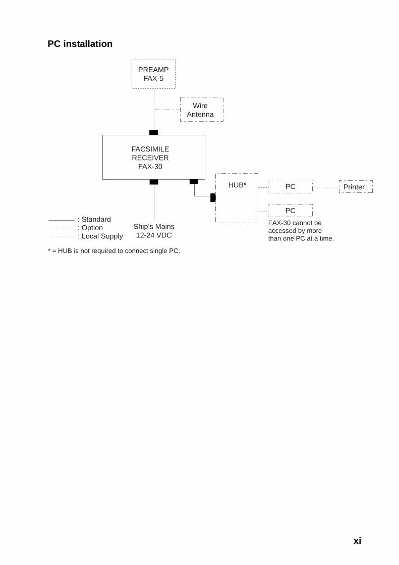
PC installation
FACSIMILERECEIVER
FAX-30
Ship’s Mains12-24 VDC
HUB* PC Printer
PC
FAX-30 cannot beaccessed by morethan one PC at a time.
: Standard: Option: Local Supply
PREAMPFAX-5
WireAntenna
* = HUB is not required to connect single PC.
xii
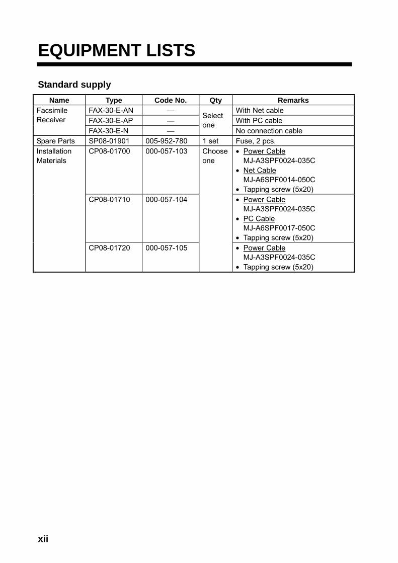
EQUIPMENT LISTS
Standard supply Name Type Code No. Qty Remarks
FAX-30-E-AN — With Net cable FAX-30-E-AP — With PC cable
Facsimile Receiver
FAX-30-E-N —
Select one
No connection cable Spare Parts SP08-01901 005-952-780 1 set Fuse, 2 pcs.
CP08-01700 000-057-103 • Power Cable MJ-A3SPF0024-035C
• Net Cable MJ-A6SPF0014-050C
• Tapping screw (5x20) CP08-01710 000-057-104 • Power Cable
MJ-A3SPF0024-035C • PC Cable
MJ-A6SPF0017-050C • Tapping screw (5x20)
Installation Materials
CP08-01720 000-057-105
Chooseone
• Power Cable MJ-A3SPF0024-035C
• Tapping screw (5x20)

xiii
Optional supply Name Type Code No. Remarks
Preamp Unit FAX-5 000-075-016 w/15 m cable Preamp Unit FAX-5 000-075-049 w/1 m cable Hose Clamp OP08-11 005-946-960 For fixing FAX-5 to a mast Whip Antenna 04S4176 000-153-122 2.6 m, for FAX-5
OP-04-2 *10* 000-041-174 OP-04-2 *20* 000-041-175 OP-04-2 *30* 000-041-176 OP-04-2 *40* 000-041-177
Extension Cable Kit
OP-04-2 *50* 000-041-178
M-connector at both ends
Cable Assy. MJA6SRMD/TM11AP8-005 000-144-463 Net conversion cable, for HUB, NavNet
Cable Assy. MJ-A6SPF0017-050C 000-159-705-11 Net conversion cable, for HUB, PC
Coaxial Plug FM-MP-7 000-161-293-10 For cable 7C2V, RG8/U, etc. Adaptor MP-M3A 000-161-295-10 For cable 3C2V, 3D2V, etc. Adaptor MP-M5A 000-161-296-10 For cable 5C2V, 5D2V, etc.
MJ-A6SPF0014-010C 000-154-027-10 1 m MJ-A6SPF0014-050C 000-154-049-10 5 m MJ-A6SPF0014-100C 000-154-050-10 10 m MJ-A6SPF0014-200C 000-154-051-10 20 m
Cable Assy. MJ
MJ-A6SPF0014-300C 000-154-052-10 30 m
Net cable
Automatic Printing Software
FAX-30-APT 005-964-310

xiv
This page intentionally left blank.

1-1
1. OVERVIEW, SETUP
1.1 Setup: NavNet and NavNet vx2 1.1.1 Controls
TrackballChooses menu items and options.Displays the mode
selection window.
Soft keys
Long press: Turns power off.Momentary press: Turns the power on;opens the display for adjustment of brilliance.
ENTER knobPush: Registers setting. Rotate: Selects menu items and options.May also be used to enter alphanumeric data.
Clears data.
Displays alarm message board.
EBLVRM GAIN
ABC1
JKL4
STU7
DEF2
MNO5
VWX8
_'#0
GHI3
PQR6
YZ&9 Enter alphanumeric data.
Opens FAX-30 menu; returns to standby.
Controls Note 1: For NavNet operating procedures, see the operator’s manual of the
NavNet display unit. Note 2: The example screens shown in this manual may not match the screens
you see. The screen you see depends on your equipment settings and system configuration.

1. OVERVIEW, SETUP
1-2
1.1.2 Preparations for using the FAX-30 The NavNet series display unit must output the date and time data sentence ZDA through the network in order to use the facsimile timer recording feature. Further, automatic navtex requires the geographical position data sentence GGA (GPS position fix data) or GLL (geographic position, latitude/longitude). Output appropriate data sentences from the NavNet display unit to the FAX-30 as follows:
1. Turn on the NavNet display unit. From the radar, plotter or echo sounder
display, press the [MENU] key. 2. Press the SYSTEM CONFIGURATION soft key. 3. Press the SYSTEM SETUP soft key. 4. Press the PORT SETUP soft key. 5. Press the OUTPUT THROUGH NETWORK soft key.
*: BWR: Rhumb line BWC: Great circle
SELECTSNTNC
RETURN
ON/OFF
AAMAPBBODBWR*DPTGGAGLLGTDMTWRMARMBRMCVHWVTGWPLXTEZDAHDTHDGMWVTTM
--ON--------
ON------
ONON--
ON----
ON--------
Select sentence window
6. Rotate the [ENTER] knob to choose GGA, GLL or ZDA. 7. Press the ON/OFF soft key to display ON. 8. Repeat steps 6 and 7 to set the other two sentences to ON. 9. Press the [MENU] key to close the menu.

1. OVERVIEW, SETUP
1-3
1.1.3 Accessing the FAX mode 1. Turn on the FAX-30 at the ship’s mains switchboard. The FAX-30 proceeds in
the following sequence: a) The FAX-30 starts initial set up, which takes about 15 seconds. b) The FAX-30 transfers (loads) data from the ROM to the RAM. At this time the
LED flashes every 0.4 seconds. c) After all data has been loaded, which takes about two minutes, the LED
flashes every two seconds, indicating the FAX-30 is ready for operation.
LED(green)
FAX-30, top view
2. Press the [DISP] key to show the display selection window.
· TURN KNOB TO SELECT MODE AND PUSH KNOB TO ENTER.· PUSH ANY SOFTKEY TO SELECT IMAGE SOURCE.
Fax mode icon
RADAR PLOTTER SOUNDER NAV DATA OVERLAY EXT VIDEO WXFAX
HOTPAGE 1 HOTPAGE 2 HOTPAGE 3 HOTPAGE 4 HOTPAGE 5 HOTPAGE 6
Display selection window 3. Rotate the [ENTER] knob to choose the WXFAX icon. 4. Push the [ENTER] knob to show the fax standby display. Note 1: The FAX-30 cannot be accessed during the 15-second start up period
that occurs after the power has been turned on. Note 2: If the FAX-30 is not connected to the NavNet display unit when the
display unit is powered, the message “AUX SOURCE IS DISCONNECTED. PUSH ENT KNOB TO EXIT.” appears. Check connections between the FAX-30 and the NavNet display unit.
Note 3: “LOAD IMAGES” is displayed while the FAX-30 is loading data.

1. OVERVIEW, SETUP
1-4
The standby display is where you begin all facsimile and navtex operations. If a facsimile image has been received, the latest facsimile image is displayed.
FAX-30
WX FAX
NAVTEX
MODESETUP
Facsimile image area
Soft keys
Standby display
1.1.4 Choosing the receive mode The FAX-30 has three modes: facsimile only, navtex only, and facsimile (timer) & navtex. Choose desired mode as follows: 1. At the facsimile standby display, press the MODE SETUP soft key.
MODESETUP
RXMODE
RETURN
RXNOTICE
(Facsimile image area)
Receive mode setup screen
2. Press the RX MODE soft key. RX MODE
WX FAXNAVTEX FAX (TIMER) & NAV
RX mode options
3. Rotate the [ENTER] knob to choose receive mode desired and press the ENTER soft key.
1. OVERVIEW, SETUP
1-5
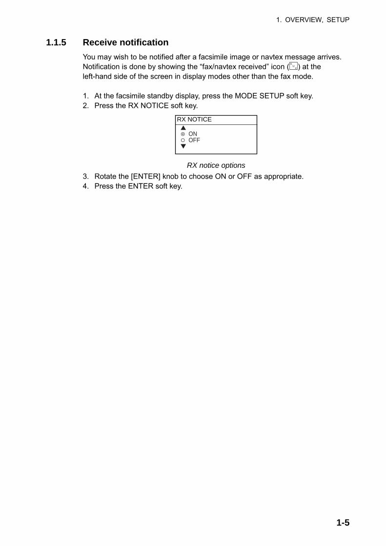
1.1.5 Receive notification You may wish to be notified after a facsimile image or navtex message arrives. Notification is done by showing the “fax/navtex received” icon ( A
U X ) at the
left-hand side of the screen in display modes other than the fax mode. 1. At the facsimile standby display, press the MODE SETUP soft key. 2. Press the RX NOTICE soft key.
RX NOTICE
ONOFF
RX notice options 3. Rotate the [ENTER] knob to choose ON or OFF as appropriate. 4. Press the ENTER soft key.

1. OVERVIEW, SETUP
1-6
1.2 Setup: PC 1.2.1 Accessing the FAX-30 top display
1. Turn on the FAX-30 at the breaker on switchboard. The FAX-30 proceeds in the following sequence:
a) The FAX-30 starts initial set up, which takes about 15 seconds. b) The FAX-30 transfers (loads) data from the ROM to the RAM. At this time the
LED flashes every 0.4 seconds. c) After all data has been loaded, which takes about two minutes, the LED
flashes every two seconds, indicating the FAX-30 is ready for operation.
2. Start up the browser software. 3. After the LED on the FAX-30 starts flashing every two seconds, type in the
FAX-30’s URL http://172.31.8.1 and then press the [Enter] key. The facsimile receiver top display appears. (For one-touch access to the FAX-30 make a bookmark.)
FACSIMILE RECEIVERFAX-30
WX FAX NAVTEXLOGOUT
Facsimile receiver top display
4. Click WX FAX for facsimile or NAVTEX for navtex to show the corresponding standby display, which is where you begin all facsimile (or navtex) operations.

1. OVERVIEW, SETUP
1-7
MENU
CHANNEL SETUP
EDIT STATION LIST
<< Top
SYSTEM SETUPRX MODE
Fax standby display
TIMER SETUP
<< Top
MENU
EDIT STATION LIST
SYSTEM SETUPRX MODE
RX SETUP
Navtex standby display
518kHz AUTO LAT/LON OK
SS=10 STBY
100N 3625.kHz IOCXX10 XXXrpm SS=XXX SN=XX STBY
Click to return to top display
Top menu
Facsimile image data (Changes with picture
received.)
Click to return to top display
Top menu
Navtex mesasge data (Changes with message
received.)
Received facsimile image thumbnails appear here.
Navtex message list appears here.
Navtex message display area
Standby displays After you are in a standby display time data is transferred from the PC to the FAX-30.
Note 1: After turning on the FAX-30 be sure to access it from the PC. Then,
even if the PC is turned off, time data is stored in the FAX-30, for use with timer recording.
Note 2: The example screens shown in this manual may not match the screens you see. The screen you see depends on your equipment settings and system configuration.

1. OVERVIEW, SETUP
1-8
1.2.2 Choosing the receive mode The FAX-30 has three modes: facsimile only, navtex only, and facsimile (timer) & navtex. Choose desired mode as follows.
1. At the facsimile or navtex standby display, click RX MODE.
WX FAX NAVTEX FAX(TIMER) & NAVTEX
OK
RX MODE< back
RX mode options
2. Click desired receive mode and then click OK. 3. Click “<back” or Back button to return to the top menu.
1.2.3 Logging out
The FAX-30 cannot be accessed simultaneously by multiple PCs or NavNet/NavNet 3D units. For this reason, log out a PC or NavNet/NavNet 3D from the FAX-30 when its use is not required. 1. At the facsimile or navtex menu display, click “<Top” to return to the facsimile
receiver top display. (See the illustration at the top of the previous page.) 2. Click LOGOUT to logout the PC or NavNet/NavNet 3D from FAX-30.
1. OVERVIEW, SETUP
1-9
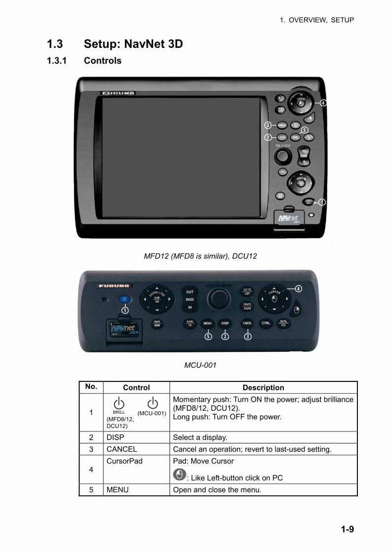
1.3 Setup: NavNet 3D 1.3.1 Controls
1
2
3
4
5
MFD12 (MFD8 is similar), DCU12
35 2
4
1
MCU-001 No. Control Description
1 BRILL
(MFD8/12,DCU12)
(MCU-001)
Momentary push: Turn ON the power; adjust brilliance (MFD8/12, DCU12). Long push: Turn OFF the power.
2 DISP Select a display. 3 CANCEL Cancel an operation; revert to last-used setting.
4 CursorPad Pad: Move Cursor
: Like Left-button click on PC 5 MENU Open and close the menu.

1. OVERVIEW, SETUP
1-10
1.3.2 How to use FAX-30 with NavNet 3D Connect the FAX-30 to the NavNet 3D. If the IP address of the FAX-30 has been changed, restore the IP address to [172.31.8.1]. For how to open the installation wizard, see the installation manual for the NavNet 3D.
1. Turn on the FAX-30 at the switchboard. (The FAX-30 does not have a power
switch.) Check if the power is on or the unit is disconnected, by monitoring the LED. a) The initialization of the FAX-30 takes approximately 15 seconds. b) Data is transferred from the ROM to the RAM. At this time the LED flashes every 0.4 seconds. c) It takes about two minutes to send data. The LED blinks every two seconds when the FAX-30 is available for operation.
2. Push the [DISP] key. 3. Push the RotoKeyTM until the display selection window, shown below,
appears.
Full screen icon
Weather icon

1. OVERVIEW, SETUP
1-11
4. The selector at the left side of the screen is choosing the "full screen" icon. Push the RotoKeyTM to choose the full screen icon.
5. Rotate the RotoKeyTM to choose the Weather icon at the bottom of the display and then push the RotoKeyTM.
6. Use the [DISP] key and the RotoKeyTM to select the Weather display.
<< Top

1. OVERVIEW, SETUP
1-12
1.3.3 Receive mode The FAX-30 has three receiving modes: WX FAX, NAVTEX, and FAX&NAVTEX.
1. Click RX MODE on the FAX-30 display.
WX FAX NAVTEX FAX(TIMER) & NAVTEX
OK
RX MODE< back
2. Click desired receive mode and then click OK. 3. Click "back" to finish.
1.3.4 Logout The FAX-30 cannot be accessed from more than one NavNet 3D unit at a time. Therefore, logout from a unit you are not using to enable access from other units.
1. Click Top on the FAX-30. 2. Click LOGOUT.

2-1
2. FAX OPERATION: NavNet, NavNet vx2
2.1 Automatic Receiving Once you choose the facsimile station from which to receive, the system goes into standby to await the start signal from the facsimile station.
2.1.1 Choosing channel
1. At the standby display, press the WX FAX soft key. Thumbnails of received images are shown.
THUMB-NAILS
SELECTIMAGE
RCVWX FAX
RETURN
JMH JUN/04 02:46 JMH JUN/05 01:29 JMH JUN/05 01:32
JMH JUN/05 03:46 JMH JUN/05 04:29 JMH JUN/05 05:21
THUMBNAILS OF RECEIVED IMAGES
Thumbnails of received images
2. Press the RCV WX FAX soft key.
CHSETUP
TIMERSETUP
STOPRX
RETURN
STARTRX
RECEIVEWX FAX100N JMH 7305.0KHZ IOC288 180rpmSS=57 SN=31
RECEIVE WX FAX display

2. FAX OPERATION: NAVNET
2-2
3. Press the CH SETUP soft key.
CHANNELSETUP
ZONE
STA
FREQ
RETURN
CH
100N JMH 3622.5kHz IOCXXX XXrpm SS=00 SN=00 RCVImage dataChanges when facsimile
picture is received.See paragraph 2.1.2.
Fax channel setup window 4. Press the ZONE soft key to display the ZONE options.
ZONE
0 PRIVATE1 NORTHWEST PACIFIC2 NORTHEAST PACIFIC3 SOUTH PACIFIC/INDIAN4 SOUTH ATLANTIC5 NORTHWEST ATLANTIC6 NORTHEAST ATLANTIC7 NORTH ATLANTIC
Zone options 5. Rotate the [ENTER] knob to choose zone desired and push the ENTER soft
key. (Zone 0 and 9 are for user-set zones.) 6. Press the STATION soft key to show the STATION options. If the ZONE
chosen at step 5 is “1 NORTHWEST PACIFIC,” for example, the STATION options are as below.
STATION
0 JMH /TOKYO 11 JMJ /TOKYO 22 JJC /KYODO 9MG3 JFA /CHUO GYOGYOU4 3SD /BEIJING5 BAF /BEIJING6 BDF /SHANGHAI7 BMF /TAIPEI
Station options (Example: stations of northwest pacific)
7. Rotate the [ENTER] knob to choose desired station and press the ENTER soft key.

2. FAX OPERATION: NAVNET
2-3
8. Press the CHANNEL soft key to show the CHANNEL options. If you have chosen “0 JMH/TOKYO 1” at step 7, for example, the CHANNEL options are as below.
CHANNEL
AUTO0 03622.5 kHz1 07795.0 kHz2 13988.5 kHz3 00079.9 kHz4 00079.9 kHz5 00079.9 kHz6 00079.9 kHz
CHANNEL
7 00079.9 kHz8 00079.9 kHz9 00079.9 kHz
Scroll screenwith ENTER knob.
Channel options (Example: JMH/Tokyo)
9. Rotate the [ENTER] knob to choose channel desired and press the ENTER soft key.
10. If necessary you may fine-tune the frequency. Press the FREQ soft key.
FREQUENCY
03622.5 kHz
Frequency entry window
11. Use the alphanumeric keys or the [ENTER] knob to enter appropriate frequency and press the ENTER soft key. (You may choose the location where to enter data by operating the trackball.)
12. Press the RETURN soft key several times to return to the standby display. Then, the FAX-30 will receive the next scheduled broadcast from the station selected. When the FAX-30 receives the start signal from the facsimile station it automatically adjusts itself to match speed, IOC (Index of Cooperation) and phase of the station’s transmitter. Facsimile images are received line by line, taking 30-40 minutes to receive depending on the size of the image and rotation speed of the drum at the facsimile transmitter. After a facsimile image is received it is compressed and stored in image memory and then posted on the “Thumbnails of received images” screen (see paragraph 2.4). This process takes from three to five minutes. You can see the image being received by pressing the WX FAX soft key on the fax standby display and then hitting the RCV WX FAX soft key.

2. FAX OPERATION: NAVNET
2-4
2.1.2 Previewing image being received To preview an image while it is being received, do the following: 1. At the fax standby display, press the WX FAX soft key. 2. Press the RCV WX FAX soft key.
RECEIVEWX FAX
Zone/Station/Channel Frequency IOC (288 or 576) Speed (60, 90, 120, 180, 240) Signal Strength (Range: 0-99, Typical: 30-70) Signal-to-Noise Ratio (Range: 0-99, Typical: 20-60)
Image beingreceived
CHSETUP
TIMERSETUP
STOPRX
RETURN
STARTRX
Receiving facsimile image
Facsimile receiving display
2.1.3 Stopping automatic receiving You can stop automatic receiving at any time by doing the following: 1. At the standby display, press the WX FAX soft key. 2. Press the RCV WX FAX soft key. 3. Press the STOP RX soft key. The indication “RCV” is replaced with “STBY.” 4. Press the RETURN soft key.

2. FAX OPERATION: NAVNET
2-5
2.2 Manually Starting, Stopping Receiving 2.2.1 Manually starting receiving
This section shows you to manually receive a facsimile broadcast. For example, you may want to receive a facsimile broadcast already in progress or receive from a facsimile station that does not use start and stop signals. Further, you may wish to stop reception to receive an image from a different station. To manually receive a facsimile, you will first need to set a channel, referring to paragraph 2.1. Then, do the following: 1. At the standby display, press the WX FAX soft key. 2. Press the RCV WX FAX soft key. 3. Press the START RX soft key.
The options shown are IOC (Index of Cooperation)/speed. START RX
288/60288/90288/120288/180288/240576/90576/90576/120
START RX
576/180576/240Rotate
[ENTER]knob toscroll.
Start RX options
4. Rotate the [ENTER] knob to choose the correct combination of IOC and speed of the facsimile transmitting station. IOC is the line density standard assigned by WMO: IOC 576, high density, IOC 288, low density. Speed is the rotation speed of the drum (on which the original image is fitted) at the facsimile transmitter: 60, 90 ,120, 180 or 240 rpm.
5. Press the ENTER soft key. 6. Press the RETURN soft key. Then, the FAX-30 will receive the current broadcast from the station selected. Facsimile images are received line by line, taking 30-40 minutes to receive depending on the size of the image and drum rotation speed at the facsimile station. After a facsimile image is received it is compressed and stored in the image memory and then posted on the “Thumbnails of received images” screen (see paragraph 2.4). This process takes 3-5 minutes. You can see the image being received by pressing the WX FAX soft key on the fax standby display and then hitting the RCV WX FAX soft key.

2. FAX OPERATION: NAVNET
2-6
Be sure to choose the correct speed and IOC, otherwise the image will be received as shown in the illustration below. You may change the IOC and speed while the image is being received.
Wrong Speed or IOC and Image
Wrong speed: "60" chosen instead of "120"
Two images are displayed.
Wrong speed: "120" chosen instead of "60"
Overlapped image appears.
Wrong IOC
The image will be extended ( or foreshortened) when "288" (or 576 is selected for transmission with the IOC of "576 (or 288)."
Wrong speed or IOC and image
2.2.2 Manually stopping receiving
1. At the standby display, press the WX FAX soft key. 2. Press the RCV WX FAX soft key. 3. Press the STOP RX soft key. 4. Press the RETURN soft key.

2. FAX OPERATION: NAVNET
2-7
2.3 Timer Receiving Most facsimile stations transmit facsimiles in accordance with a schedule issued by relative meteorological observatory. (You can find facsimile schedules in the publication “Meteorological Facsimile Broadcasts,” available through meteorological observatory bodies.) If you wish to receive a certain facsimile broadcast on a daily basis, therefore, the timer receiving mode will virtually allow you “hands-off” automatic operation. 30 timer programs may be set.
2.3.1 Setting timer receiving schedule Note that the data sentence ZDA must be output through the network for the timer to function. 1. At the standby display, press the WX FAX soft key. 2. Press the RCV WX FAX soft key. 3. Press the TIMER SETUP soft key.
TIMERSETUP
STARTTIMER
RETURN
PROGLIST
No. 05 10:30-14:05 100N JMH 3662.5 kHzNo. 06 14:30-16:40 100N JMH 3662.5 kHzNo. 07 16:40-19:00 100N JMH 3662.5 kHzNo. 01 19:05-19:15 100N JMH 3662.5 kHz
Timer schedule,in time orderfrom closestto furthest. Only the latest10 programsare displayed.
Timer setup screen 4. Press the PROG LIST soft key.
PROGRAMLIST
EDIT
ON/OFF
RETURN
CLEARALL
No.01 12:30-14:00 100N JMH ONNo.02 NOT PROGRAMMEDNo.03 NOT PROGRAMMEDNo.04 NOT PROGRAMMEDNo.05 NOT PROGRAMMEDNo.06 NOT PROGRAMMEDNo.07 NOT PROGRAMMEDNo.08 NOT PROGRAMMEDNo.09 NOT PROGRAMMEDNo.10 NOT PROGRAMMEDNEXT PAGE
Start, end timeFacsimile station
Timer ON
Zone/Station/Channel
Timer schedule list

2. FAX OPERATION: NAVNET
2-8
5. Rotate the [ENTER] knob to choose program number desired and then press the EDIT soft key.
EDITPROGRAM
EDIT
SAVE
CANCEL
ZONE 1 NORTHWEST PACIFICSTATION 0 JMH/TOKYO No.1CHANNEL 0 3622.5 kHzIOC AUTOSPEED AUTOSTART TIME 00:00END TIME 00:00FREQUENCY 00000.0 kHz
CLEAR
Timer schedule menu
6. ZONE is selected; press the EDIT soft key. ZONE
0 PRIVATE1 NORTHWEST PACIFIC2 NORTHEAST PACIFIC3 SOUTH PACIFIC/INDIAN4 SOUTH ATLANTIC5 NORTHWEST ATLANTIC6 NORTHEAST ATLANTIC7 NORTH ATLANTIC
Zone options
7. Rotate the [ENTER] knob to choose zone desired and press the ENTER soft key.
8. Rotate the [ENTER] knob to choose STATION and press the EDIT soft key. If you have chosen “1 NORTHWEST PACIFIC” at step 7, for example, the STATION options are as below.
STATION
0 JMH /TOKYO 11 JMJ /TOKYO 22 JJC /KYODO 9MG3 JFA /CHUO GYOGYOU4 3SD /BEIJING5 BAF /BEIJING6 BDF /SHANGHAI7 BMF /TAIPEI
Station options (Example: N Pacific W Part) 9. Rotate the [ENTER] knob to choose desired station and press the ENTER
soft key.

2. FAX OPERATION: NAVNET
2-9
10. Rotate the [ENTER] knob to choose CHANNEL and press the EDIT soft key. If you have chosen “0 JMH/TOKYO 1” at step 9, for example, the CHANNEL display looks as below.
Channel options (Example: station JMH) 11. Rotate the [ENTER] knob to choose channel desired and press the ENTER
soft key. Choose AUTO for automatic selection of channel. (Most stations transmit the same message over several frequencies, so if you are unsure of the channel choose AUTO.)
12. Rotate the [ENTER] knob to choose IOC and press the EDIT soft key.
IOC
AUTO288576
IOC options 13. Rotate the [ENTER] knob to choose the IOC of the facsimile station and
press the ENTER soft key. If you are unsure of the IOC, choose AUTO for automatic selection of IOC.
14. Rotate the [ENTER] knob to choose SPEED and press the EDIT soft key. SPEED
AUTO6090120180240
Drum speed options
15. Rotate the [ENTER] knob to choose drum rotating speed at the facsimile station and press the ENTER soft key. If you are unsure of the speed, choose AUTO for automatic selection of speed.
16. Rotate the [ENTER] knob to choose START TIME and press the EDIT soft key.
START TIME
00:00
Start time entry window

2. FAX OPERATION: NAVNET
2-10
17. Enter a start time in 24-hour notation, about two minutes earlier than actual start time to allow for detection of the start signal and press the ENTER soft key.
18. Rotate the [ENTER] knob to choose END TIME and press the EDIT soft key.
END TIME
00:00
End time entry window
19. Enter end time in 24-hour notation about two minutes later than actual end time to allow for detection of the stop signal, and press the ENTER soft key. Note: Two programs that overlap each other will cause the program having
the later start time to be disregarded. For example, if the start and end times of program no. 1 are 01:00 and 02:00 and those of program no. 2 are 01:30 to 3:00, program no. 2 will be disregarded.
20. If necessary you may fine-tune the receive frequency. Rotate the [ENTER] knob to choose FREQUENCY and press the EDIT soft key. The frequency selected at step 10 appears.
FREQUENCY
03522.5 kHz
Frequency entry window 21. Enter frequency with the numeric keys and press the ENTER soft key. 22. Press the SAVE soft key.
SAVE
YESNO
Save window
23. Rotate the [ENTER] knob to choose YES and push the [ENTER] knob. 24. Repeat steps 4-23 to set other timer schedules. 25. Press the RETURN soft key. 26. Press the START TIMER soft key.
START TIMER
STARTSTOP
Start timer options
26. Rotate the [ENTER] knob to choose START and press the ENTER soft key. 27. Press the RETURN soft key.

2. FAX OPERATION: NAVNET
2-11
Then, the FAX-30 will receive facsimile broadcasts according to the timer schedule. Facsimile images are received line by line, taking 30-40 minutes to receive depending on the size of the image and drum rotation speed at the facsimile station. After a facsimile image is received it is compressed and stored in the image memory and then posted on the facsimile standby display screen. This process takes 3-5 minutes. You can see the image being received by pressing the WX FAX soft key on the fax standby display and then hitting the RCV WX FAX soft key. Note: To disable all timer programs do the following: 1. At the standby display, press the WX FAX soft key. 2. Press the RCV WX FAX soft key. 3. Press the TIMER SETUP soft key. 4. Rotate the [ENTER] knob to choose STOP. 5. Press the ENTER soft key. 6. Press the RETURN soft key.
2.3.2 Turning on/off specific timer programs You may turn specific timer programs on or off as appropriate as follows: 1. At the standby display, press the WX FAX soft key. 2. Press the RCV WX FAX soft key. 3. Press the TIMER SETUP soft key. 4. Press the PROG LIST soft key. 5. Rotate the [ENTER] knob to choose a timer receiving schedule. 6. Press the ON/OFF soft key to display ON or OFF next to timer program data. 7. Press the RETURN soft key several times to return to the standby display.
2.3.3 Clearing all timer programs You may clear all timer programs as follows: 1. At the standby display, press the WX FAX soft key. 2. Press the RCV WX FAX soft key. 3. Press the TIMER SETUP soft key. 4. Press the PROG LIST soft key. 5. Press the CLEAR ALL soft key.
CLEAR ALL
YESNO
Clear all options
6. Rotate the [ENTER] knob to choose YES and push the ENTER knob. All timer programs disappear.
7. Press the RETURN soft key several times to return to the standby display.

2. FAX OPERATION: NAVNET
2-12
2.4 Displaying Facsimile Images 1. At the standby display, press the WX FAX soft key. Thumbnails of images
received are shown on the display. The equipment stores as many as 12 images, on two pages. If more than six images are stored, PREV PAGE and NEXT PAGE soft keys appear in order to navigate between pages. When the image storage capacity is exceeded, the oldest image is automatically deleted to make room for the latest.
THUMB-NAILS
SELECTIMAGE
RETURN
Receive dataStation, date and
time image received
Note: If date or timeis incorrect, confirmthat data sentenceZDA is output.
JMH JUN/04 02:46 JMH JUN/05 01:29 JMH JUN/05 01:32
JMH JUN/05 03:46 JMH JUN/05 04:29 JMH JUN/05 05:21
THUMBNAILS OF RECEIVED IMAGES
RCVWX FAX
NEXTPAGE
Thumbnails of received images
2. Use the [ENTER] knob to select the facsimile image to process and then press the SELECT IMAGE soft key or push the [ENTER] knob. You can scroll the image with the trackball.
EDITIMAGE
ZOOMIN
LOCK/ERASE
RETURN
ROTATE
0 10 20 30 40102N JMH 7305.0kHz IOC576 120rpm JUN/05 01:26 WXFAX
IMAGE
Time received
Date received
Frequency
Station
Zone/Station/Channel
ScaleUsed for
phase tuning.See para 2.5.1
Drum speed at fax station
Index of Cooperation
Facsimile image

2. FAX OPERATION: NAVNET
2-13
2.5 Processing Facsimile Images 2.5.1 Phase mismatch
When the FAX-30 starts receiving a broadcast already in progress, or noise prevents detection of the phasing signal, the image may be divided into two parts by a thick black (or white) stripe called a dead sector. This phenomenon is due to phase mismatching. When this occurs, correct phase mismatching, after the facsimile has been received.
0 10 20 30 40
Dead sector (can be white)Dead sectorcenter at "15" Example of phase mismatching
1. With a facsimile image displayed (see paragraph 2.4), press the EDIT IMAGE soft key.
10 20 300 40102N JMH 7305.0kHz IOC576 120rpm JUN/05 01:26
PHASE
SYNC
EDITCOLOR
RETURN
NOISEREJECT
EDITIMAGE
Facsimile image with dead sector
2. Press the PHASE soft key.
PHASE
00
Phase entry window
3. Read the scale to find the center of the dead sector and enter it in the phase entry window. For example, in the illustration above the dead sector is centered at "15" on the scale, so you would enter “15”. The setting range is 00 to 40.
4. Press the ENTER soft key. 5. Press the RETURN soft key several times to return to the standby display.
2. FAX OPERATION: NAVNET
2-14
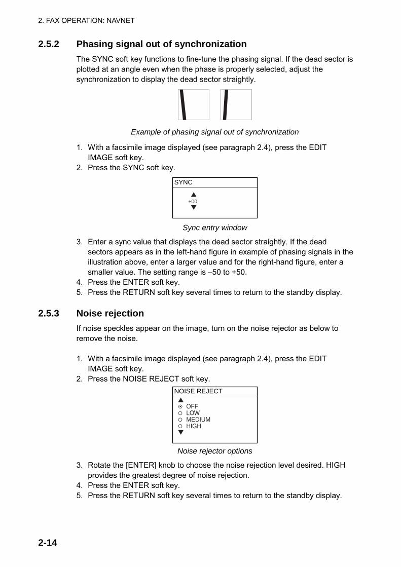
2.5.2 Phasing signal out of synchronization The SYNC soft key functions to fine-tune the phasing signal. If the dead sector is plotted at an angle even when the phase is properly selected, adjust the synchronization to display the dead sector straightly.
Example of phasing signal out of synchronization
1. With a facsimile image displayed (see paragraph 2.4), press the EDIT IMAGE soft key.
2. Press the SYNC soft key.
SYNC
+00
Sync entry window
3. Enter a sync value that displays the dead sector straightly. If the dead sectors appears as in the left-hand figure in example of phasing signals in the illustration above, enter a larger value and for the right-hand figure, enter a smaller value. The setting range is –50 to +50.
4. Press the ENTER soft key. 5. Press the RETURN soft key several times to return to the standby display.
2.5.3 Noise rejection If noise speckles appear on the image, turn on the noise rejector as below to remove the noise. 1. With a facsimile image displayed (see paragraph 2.4), press the EDIT
IMAGE soft key. 2. Press the NOISE REJECT soft key.
NOISE REJECT
OFFLOWMEDIUMHIGH
Noise rejector options
3. Rotate the [ENTER] knob to choose the noise rejection level desired. HIGH provides the greatest degree of noise rejection.
4. Press the ENTER soft key. 5. Press the RETURN soft key several times to return to the standby display.

2. FAX OPERATION: NAVNET
2-15
2.5.4 Image color The facsimile image is transmitted in monochrome (black and white) or gray scale (16 gradations). After an image has been received, you can choose the color arrangement among monochrome, gray scale and color (three patterns). 1. With a facsimile image displayed (see paragraph 2.4), press the EDIT
IMAGE soft key. 2. Press the EDIT COLOR soft key. 3. Press the COLOR soft key.
COLOR
MONOCHROMEGRAY SCALEBLUE-REDWHITE-BLUEPINK-BLACK
Color options 4. Rotate the [ENTER] knob to choose MONOCHROME, GRAY SCALE,
BLUE-RED, WHITE-BLUE or PINK-BLACK as appropriate. MONOCHROME: Monochrome black and white GRAY SCALE: 16 gray tones BLUE-RED: Shades of blue to red WHITE-BLUE: Shades of white to blue PINK-BLACK: Shades of pink to black
5. Press the ENTER soft key. 6. Press the RETURN soft keys several times to return to the standby display.
2.5.5 Image format
The facsimile image is usually transmitted with black text on a white background. Some stations, however, print white characters on a black background. If, for some reason, the image received cannot be read in its transmitted image format you may change it as follows: 1. With a facsimile image displayed (see paragraph 2.4), press the EDIT
IMAGE soft key. 2. Press the EDIT COLOR soft key. 3. Press the REVERSE IMAGE soft key.
REVERSE IMAGE
NORMALREVERSE
Reverse image options 4. Rotate the [ENTER] knob to choose NORMAL or REVERSE as appropriate. 5. Press the ENTER soft key. 6. Press the RETURN soft key several times to return to the standby display.
2. FAX OPERATION: NAVNET
2-16
2.5.6 Zooming images You may double the size of a facsimile image as follows: 1. Display the facsimile image you wish to process, referring to paragraph 2.4. 2. Press the ZOOM IN soft key. To restore the normal size image, press the ZOOM OUT key.
2.5.7 Rotating images You may rotate facsimile images as follows: 1. Display the facsimile image you wish to process, referring to paragraph 2.4. 2. Press the ROTATE soft key. 3. Press the CW (Clockwise) soft key to rotate the image 90° clockwise; CCW
(Counterclockwise) soft key to rotate it 90° counterclockwise.
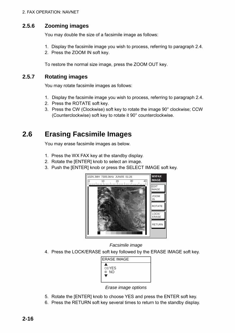
2.6 Erasing Facsimile Images You may erase facsimile images as below. 1. Press the WX FAX key at the standby display. 2. Rotate the [ENTER] knob to select an image. 3. Push the [ENTER] knob or press the SELECT IMAGE soft key.
102N JMH 7305.0kHz JUN/05 01:26
EDITIMAGE
ZOOMIN
LOCK/ERASE
RETURN
ROTATE
WXFAXIMAGE0 10 20 30 40
Facsimile image 4. Press the LOCK/ERASE soft key followed by the ERASE IMAGE soft key.
ERASE IMAGE
YESNO
Erase image options
5. Rotate the [ENTER] knob to choose YES and press the ENTER soft key. 6. Press the RETURN soft key several times to return to the standby display.

2. FAX OPERATION: NAVNET
2-17
2.7 Preventing Erasure of Facsimile Images When facsimile image storage capacity is exceeded, the oldest facsimile image is erased to make room for the latest. If you have an image that you want to keep, you can prevent its erasure by using the “lock image” feature. You can lock all images, however you may not be able to receive a new image if there is not sufficient memory remaining to store the new image. 1. Press the WX FAX key at the standby display. 2. Rotate the [ENTER] knob to select an image and then push the [ENTER]
knob or press the SELECT IMAGE soft key. 3. Press the LOCK/ERASE soft key followed by the LOCK IMAGE soft key. 4. Rotate the [ENTER] knob to choose ON and press the ENTER soft key. 5. Press the RETURN soft key several times to return to the standby display. The locked image’s data appears in red at the THUMBNAILS OF RECEIVED IMAGES screen. To release the lock image feature for a particular image, choose OFF at the step 4 in the above procedure.

2. FAX OPERATION: NAVNET
2-18
2.8 Adding Facsimile Channels The FAX-30 provides a free memory for the user to store 320 channels. 1. Press the [MENU] key to show the FAX-30 menu.
FAX-30
EDIT WX FAX STATION
EDIT NAVTEX STATION
FAX-30 SYSTEM SETUP
FAX-30 top
2. Press the EDIT WX FAX STATION soft key. EDITSTATION
EDIT
SAVE
RETURN
ZONE 0 PRIVATESTATION 0 PRV/CHANNEL 0 00079.9 kHzREVERSE IMAGE NORMALFREQUENCY 00079.9 kHzCALL SIGN PRVSTATION NAME - - - - - - - - - - - - -
Edit facsimile station menu
3. ZONE is selected; press the EDIT soft key.
ZONE
0 PRIVATE1 NORTHWEST PACIFIC2 NORTHEAST PACIFIC3 SOUTH PACIFIC/INDIAN4 SOUTH ATLANTIC5 NORTHWEST ATLANTIC6 NORTHEAST ATLANTIC7 NORTH ATLANTIC
Zone options 4. Rotate the [ENTER] knob to choose a zone and push the EDIT soft key.
(Zone 0 and 9 are for user zones.)

2. FAX OPERATION: NAVNET
2-19
5. Rotate the [ENTER] knob to choose STATION and press the EDIT soft key. If the ZONE chosen at step 4 is “1 NORTHWEST PACIFIC,” for example, the STATION options are as below.
STATION
0 JMH /TOKYO 11 JMJ /TOKYO 22 JJC /KYODO 9MG3 JFA /CHUO GYOGYOU4 3SD /BEIJING5 BAF /BEIJING6 BDF /SHANGHAI7 BMF /TAIPEI
Station options (Example: stations of northwest pacific) 6. Rotate the [ENTER] knob to choose a station and press the ENTER soft key. 7. Rotate the [ENTER] knob to choose CHANNEL and press the EDIT soft key.
If the station chosen at step 8 is “0 JMH/TOKYO No.1,” for example, the CHANNEL options are as below.
Channel options (Example: JMH/Tokyo) 8. Rotate the [ENTER] knob to choose a channel and press the ENTER soft
key. 9. Rotate the [ENTER] knob to choose REVERSE IMAGE and press the EDIT
soft key.
REVERSE IMAGE
NORMALREVERSE
Reverse image options 10. The normal facsimile image format has black text on a white background.
Some stations, however, print white characters on a black background. This information is programmed into the memory thus you need not designate image format. However, if you are entering frequency data of a newly established station whose image format is reverse of the normal image, rotate the [ENTER] knob to choose REVERSE. Press the ENTER soft key after making your selection.

2. FAX OPERATION: NAVNET
2-20
11. If you want to enter a frequency, call sign or station name other than that shown at CHANNEL and STATION, respectively, rotate the [ENTER] knob to choose FREQUENCY, CALL SIGN or STATION NAME as appropriate and press the EDIT soft key. One of the following displays appears depending on your selection.
FREQUENCY
00003.4 kHz
CALL SIGN
JMH
STATION NAME
TOKYO
Frequency Call Sign Station Name
Frequency, call sign and station name entry windows 12. Use the alphanumeric keys or the [ENTER] knob to enter appropriate data
and press the ENTER soft key. You can shift the cursor by rotating the trackball.
13. Press the SAVE soft key. 14. Rotate the trackball to choose YES and then push the [ENTER] knob. 15. Press the [MENU] key to close the menu.

3-1
3. FAX OPERATION: NavNet 3D, PC
3.1 Automatic Receiving 3.1.1 Starting receiving
1. At the facsimile standby display, click CHANNEL SETUP on the top menu.
CHANNEL SETUP
FREQUENCY 03622.5 kHz
RCV STOP
ZONE
STATION
CHANNEL
OK
< back1: NORTHWEST PACIFIC
0: JMH/TOKYO 1
AUTO
Channel setup menu 2. Click the arrow button on ZONE and choose desired zone. 3. Click the arrow button on STATION and choose desired station. See page
AP-2 for station number. 4. Click the arrow button on CHANNEL and choose desired channel. Choose
AUTO if you are unsure of channel. (Most stations transmit the same message over several frequencies, so if you are unsure of the channel choose AUTO.)
5. If necessary you may fine-tune the frequency. Click anywhere inside the FREQUENCY box and enter frequency. For a PC, enter numeric value from the keyboard.
6. Click OK and then click “<back” or Back button to return to the top menu.
Then, the FAX-30 will receive the next scheduled broadcast from the station selected. When the FAX-30 receives the start signal from the facsimile station it automatically adjusts itself to match speed, IOC (Index of Cooperation) and phase of the station’s transmitter. Facsimile images are received, taking 30-40 minutes to receive depending on the size of the image. After a facsimile image is received it is compressed and stored in the image memory and then posted on the facsimile standby display screen. This process takes 3-5 minutes.
3.1.2 Stopping receiving
You may stop receiving at any time by doing the following:
1. At the facsimile standby display, click CHANNEL SETUP on the top menu. 2. Click RCV STOP.
3. FAX OPERATION: PC
3-2
3.2 Timer Receiving Most facsimile stations transmit facsimile signals in accordance with a schedule issued by relative meteorological observatory. (You can find facsimile schedules in the publication “Meteorological Facsimile Broadcasts,” available through meteorological observatory bodies.) If you wish to receive a certain facsimile broadcast on a daily basis, therefore, the timer receiving mode will virtually allow you “hands-off” automatic operation. 30 timer programs may be set.
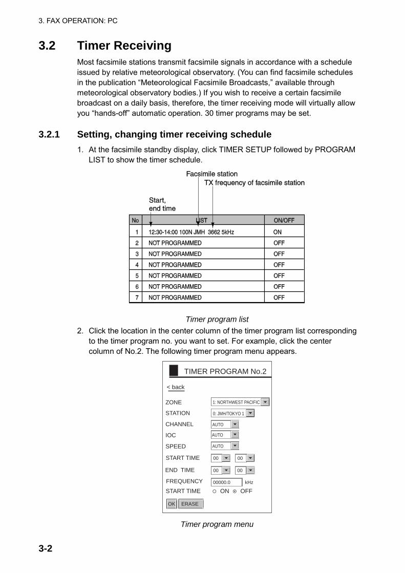
3.2.1 Setting, changing timer receiving schedule 1. At the facsimile standby display, click TIMER SETUP followed by PROGRAM
LIST to show the timer schedule.
Timer program list
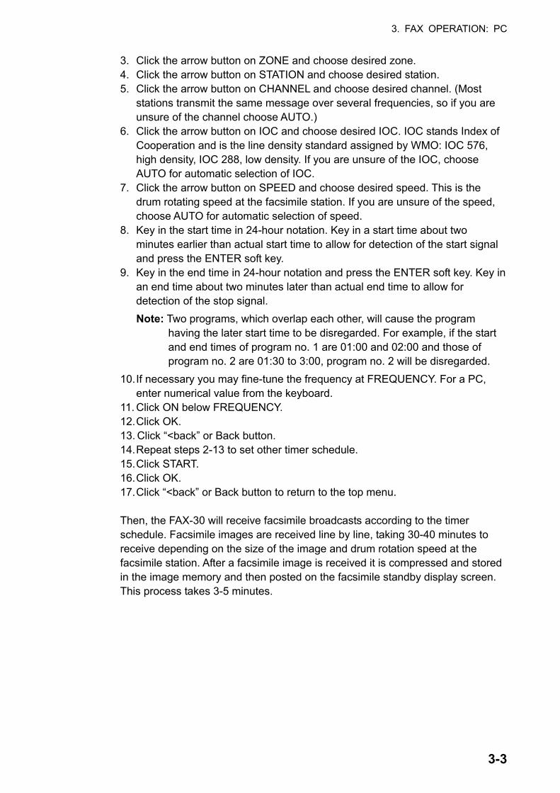
2. Click the location in the center column of the timer program list corresponding to the timer program no. you want to set. For example, click the center column of No.2. The following timer program menu appears.
OK
TIMER PROGRAM No.2
ZONE
STATION
ERASE
00000.0 kHz
END TIME
CHANNEL
IOC
SPEED AUTO
AUTO
AUTO
START TIME ON OFF
< back
START TIME
FREQUENCY
1: NORTHWEST PACIFIC
0: JMH/TOKYO 1
00 00
00 00
Timer program menu
3. FAX OPERATION: PC
3-3
3. Click the arrow button on ZONE and choose desired zone. 4. Click the arrow button on STATION and choose desired station. 5. Click the arrow button on CHANNEL and choose desired channel. (Most
stations transmit the same message over several frequencies, so if you are unsure of the channel choose AUTO.)
6. Click the arrow button on IOC and choose desired IOC. IOC stands Index of Cooperation and is the line density standard assigned by WMO: IOC 576, high density, IOC 288, low density. If you are unsure of the IOC, choose AUTO for automatic selection of IOC.
7. Click the arrow button on SPEED and choose desired speed. This is the drum rotating speed at the facsimile station. If you are unsure of the speed, choose AUTO for automatic selection of speed.
8. Key in the start time in 24-hour notation. Key in a start time about two minutes earlier than actual start time to allow for detection of the start signal and press the ENTER soft key.
9. Key in the end time in 24-hour notation and press the ENTER soft key. Key in an end time about two minutes later than actual end time to allow for detection of the stop signal. Note: Two programs, which overlap each other, will cause the program
having the later start time to be disregarded. For example, if the start and end times of program no. 1 are 01:00 and 02:00 and those of program no. 2 are 01:30 to 3:00, program no. 2 will be disregarded.
10. If necessary you may fine-tune the frequency at FREQUENCY. For a PC, enter numerical value from the keyboard.
11. Click ON below FREQUENCY. 12. Click OK. 13. Click “<back” or Back button. 14. Repeat steps 2-13 to set other timer schedule. 15. Click START. 16. Click OK. 17. Click “<back” or Back button to return to the top menu. Then, the FAX-30 will receive facsimile broadcasts according to the timer schedule. Facsimile images are received line by line, taking 30-40 minutes to receive depending on the size of the image and drum rotation speed at the facsimile station. After a facsimile image is received it is compressed and stored in the image memory and then posted on the facsimile standby display screen. This process takes 3-5 minutes.

3. FAX OPERATION: PC
3-4
3.2.2 Turning on/off specific timer programs 1. At the facsimile standby display, click TIMER SETUP. 2. Click PROGRAM LIST. 3. Click the center column of the program no. you want to turn on or off. 4. Click ON or OFF as appropriate. 5. Click OK. 6. Click “<back” or Back button to return to the top menu.
3.2.3 Clearing all timer programs
You may clear all timer programs as follows: 1. At the facsimile standby display, click TIMER SETUP. 2. Click PROGRAM LIST. 3. Click CLEAR ALL at the top of the screen. You are asked “Are you sure to
clear all?” 4. Click Ok to reset; Cancel to escape. 5. Click “<back” or Back button to return to the top menu.
3. FAX OPERATION: PC
3-5
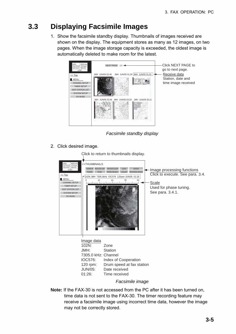
3.3 Displaying Facsimile Images 1. Show the facsimile standby display. Thumbnails of images received are
shown on the display. The equipment stores as many as 12 images, on two pages. When the image storage capacity is exceeded, the oldest image is automatically deleted to make room for the latest.
MENU
CHANNEL SETUP
EDIT STATION LIST
<< Top
SYSTEM SETUPRX MODE
TIMER SETUP
Receive dataStation, date andtime image received
JMH JUN/04 02:46 JMH JUN/05 01:29 JMH JUN/05 01:32
JMH JUN/05 03:46 JMH JUN/05 04:29 JMH JUN/05 05:21
100N 3625.kHz IOCXX10 XXXrpm SS=XXX SN=XX STBY
NEXT PAGE 1/2 Click NEXT PAGE togo to next page.
Facsimile standby display 2. Click desired image.
MENU
CHANNEL SETUP
EDIT STATION LIST
<< Top
SYSTEM SETUPRX MODE
TIMER SETUP
100N 3625.kHz IOCXX10 XXXrpm SS=XXX SN=XX STBY
0 10 20 30 40
102N JMH 7305.0kHz IOC576 120rpm JUN/05 01:26
ScaleUsed for phase tuning.See para. 3.4.1.
<<THUMBNAILS
ROTATE CCW
NOISE REJECT
ZOOM IN
PHASE
ROTATE CW
SYNC
LOCK
COLOR
ERASE
REVERSE IMAGE
Click to return to thumbnails display.
Image processing functionsClick to execute. See para. 3.4.
Image data102N: ZoneJMH: Station7305.0 kHz: ChannelIOC576: Index of Cooperation120 rpm: Drum speed at fax stationJUN/05: Date received01:26: Time received
Facsimile image
Note: If the FAX-30 is not accessed from the PC after it has been turned on, time data is not sent to the FAX-30. The timer recording feature may receive a facsimile image using incorrect time data, however the image may not be correctly stored.

3. FAX OPERATION: PC
3-6
3.4 Processing Facsimile Images 3.4.1 Phase mismatch
When the FAX-30 starts receiving a broadcast already in progress, or noise prevents detection of the phasing signal, the image may be divided into two parts by a thick black (or white) stripe called a dead sector. This phenomenon is due to phase mismatching. When this occurs, correct phase mismatching, after the facsimile has been received.
0 10 20 30 40
Dead sector (can be white)Dead sectorcenter at "15"
Example of phase mismatching 1. With a facsimile image displayed, click PHASE.
OK
PHASE< back
0
Phase entry window
2. Read the scale to find the center of the dead sector and enter it in the phase entry window. For example, if dead sector is centered at "15" on the scale, as in the illustration at the top of the page, enter “15”. The setting range is 00 to 40.
3. Click OK and then click “<back” or Back button to return to the top menu.

3. FAX OPERATION: PC
3-7
3.4.2 Phasing signal out of synchronization The SYNC soft key functions to fine-tune the phasing signal. If the dead sector is plotted at an angle even when the phase is properly selected, adjust the synchronization to display the dead sector straightly.
Example of phasing signal out of synchronization
1. With a facsimile image displayed, click SYNC.
OK
SYNC< back
0
Sync options
2. Enter a sync value that displays the dead sector straightly and then click OK. If the dead sectors appears as in the left-hand figure above, enter a larger value and for the right-hand figure, enter a smaller value. The setting range is –50 to +50.
3. Click OK and then “<back” or Back button to return to the top menu.
3.4.3 Noise rejection If noise speckles appear on the image, turn on the noise rejector as below to remove the noise. 1. With a facsimile image displayed, click NOISE REJECT.
OK
NOISE REJECT
OFFLOWMEDIUMHIGH
< back
Noise rejector options 2. Click the noise rejection level desired and then click OK. HIGH provides the
greatest degree of noise rejection. 3. Click OK and then “<back” or Back button to return to the top menu.
3. FAX OPERATION: PC
3-8
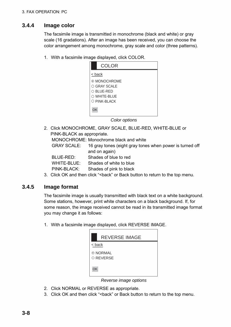
3.4.4 Image color The facsimile image is transmitted in monochrome (black and white) or gray scale (16 gradations). After an image has been received, you can choose the color arrangement among monochrome, gray scale and color (three patterns). 1. With a facsimile image displayed, click COLOR.
COLOR
MONOCHROMEGRAY SCALEBLUE-REDWHITE-BLUEPINK-BLACK
< back
OK
Color options
2. Click MONOCHROME, GRAY SCALE, BLUE-RED, WHITE-BLUE or PINK-BLACK as appropriate. MONOCHROME: Monochrome black and white GRAY SCALE: 16 gray tones (eight gray tones when power is turned off
and on again) BLUE-RED: Shades of blue to red WHITE-BLUE: Shades of white to blue PINK-BLACK: Shades of pink to black
3. Click OK and then click “<back” or Back button to return to the top menu.
3.4.5 Image format The facsimile image is usually transmitted with black text on a white background. Some stations, however, print white characters on a black background. If, for some reason, the image received cannot be read in its transmitted image format you may change it as follows: 1. With a facsimile image displayed, click REVERSE IMAGE.
OK
REVERSE IMAGE
NORMALREVERSE
< back
Reverse image options
2. Click NORMAL or REVERSE as appropriate. 3. Click OK and then click “<back” or Back button to return to the top menu.

3. FAX OPERATION: PC
3-9
3.4.6 Rotating images With a facsimile image displayed, click ROTATE CW or ROTATE CCW as appropriate. The image is rotated 90° in the direction selected.
3.4.7 Zooming images You may double the size of a facsimile image as follows: 1. Display the facsimile image you wish to process. 2. Click ZOOM IN. To restore the normal size image, click ZOOM OUT.
3.4.8 Saving images You may save images to your PC for future reference. 1. At the thumbnails display, click the facsimile image you wish to save. 2. Click ZOOM IN to enlarge the image. (The image is too small if not
enlarged.) 3. Place the cursor on the facsimile image and click the right button on the
mouse. 4. Click the “Save Picture As…” The “Save” window appears. 5. Choose directory, enter file name and click the Save button.
3.5 Erasing Facsimile Images You may erase facsimile images as below. 1. Display the facsimile image you wish to erase. 2. Click ERASE. 3. You are asked if you are sure to erase the image. Click OK to erase the
image; Cancel to escape.

3. FAX OPERATION: PC
3-10
3.6 Preventing Erasure of Facsimile Images When facsimile image storage capacity is exceeded, the oldest facsimile image is erased to make room for the latest. If you have an image that you want to keep, you can prevent its erasure by using the “lock” feature. You can lock all images, however you may not be able to receive a new image if there is not sufficient memory remaining to store the new image. 1. Display the facsimile image you want to lock. 2. Click LOCK.
OK
LOCK
ONOFF
< back
Lock options 3. Choose ON. 4. Click OK and then click “<back” or Back button to return to the top menu. The locked image’s data appears in red, at the facsimile standby display. To release the lock feature for a particular image, choose OFF at the step 3 in the above procedure.

3. FAX OPERATION: PC
3-11
3.7 Adding Facsimile Channels The FAX-30 provides a free memory for the user to store 320 channels. 1. At the standby display, click EDIT STATION LIST.
EDIT STATION LIST
FREQUENCY
OK
REVERSEIMAGE
CALL SIGN PRV
STATIONNAME
ZONE
STATION
CHANNEL
< back
79.9 kHz
0: PRIVATE
0: 79.9 kHz
NORMAL
0: PRV/
Edit station list menu
2. Click the arrow button on ZONE and choose desired zone. 3. Click the arrow button on STATION and choose desired station. 4. Click the arrow button on CHANNEL and choose desired image format. 5. The normal facsimile image format has black text on a white background.
Some stations, however, print white characters on a black background. This information is programmed into the memory thus you need not designate image format. However, if you are entering frequency data of a newly established station whose image format is reverse of the normal image, choose REVERSE. Note: For a PC, enter a value at steps 6, 7 and 8 from the keyboard.
6. If necessary, you may fine-tune the frequency shown in FREQUENCY. 7. Enter station’s CALL SIGN. 8. Enter STATION’S NAME. 9. Click OK. 10. Click “<back” or Back button to return to the top menu.

3. FAX OPERATION: PC
3-12
(This page intentionally left blank.)

4-1
4. NAVTEX OPERATION: NavNet and NavNet vx2
4.1 About Navtex Messages
4.1.1 Message categories Navtex stations throughout the world provide mariners with weather and navigational navtex messages. These messages carry a four character header code which identifies transmitting station, category of message, and message number, numbered from 00 to 99. Message number 00 is reserved for important emergency messages. The categories of messages available in the navtex system are as below. A: Coastal navigational warning H: Loran message B: Meteorlogical warning I: Omega message C: Ice report J: Differential Omega message D: Search and Rescue Alert K: Other electronic navigator system message E: Meteorological forecast L: Navarea warnings F: Pilot message V to Y: No category allocated G: Decca message Z: QRU (no message on hand)
The user may select which message categories to receive and the stations from which to receive them.
Note: It is recommended to minimally receive categories A, B, D and L because
they are important for navigation.
4.1.2 Receiving navtex messages To receive navtex messages, set the receive mode for “navtex only” or “fax(timer) & navtex”, referring to paragraph 1.1.3 for the procedure.

4. NAVTEX OPERATION: NAVNET
4-2
4.2 Setting Up Navtex Stations, Messages, Alarms You may freely select the navtex stations from which to receive and the messages categories to receive. Further, you may enable or disable received message alarms. 1. At the standby display, press the NAVTEX soft key. If you have received
some navtex messages, their data are shown as below. NAVTEX
SELECTMSG
RETURN
RXSETUP
1. IA55 JUN/06 03:57 518kHz2. IA53 JUN/06 03:58 518kHz3. IA52 JUN/06 03:59 518kHz4. IA48 JUN/06 04:01 518kHz
RCVNAVTEX Appears when the mode is
NAVTEX or FAX(TIMER)&NAVTEX
Navtex message data display
2. Press the RX SETUP soft key. RXSETUP
EDIT
RETURN
FREQUENCY 518 kHzSTA. SELECTION MODE MANUALSTATION SELECTION .MESSAGE SELECTIONMAX ERROR RATE 33%ALARM (SAR MSG) OFFALARM (WARNING MSG) OFF
RX setup menu
3. FREQUENCY is selected; press the EDIT soft key.
FREQUENCY
490 kHz518 kHz
Navtex frequency options
4. Rotate the [ENTER] knob to choose 490 kHz or 518 kHz depending on the station and press the ENTER soft key.

4. NAVTEX OPERATION: NAVNET
4-3
5. Rotate the [ENTER] knob to choose STA. SELECTION MODE and press the EDIT soft key.
STA. SELECTION MODE
MANUALAUTO
Navtex station mode options
6. Rotate the [ENTER] knob to choose navtex station selection method and press the [ENTER] soft key. AUTO requires position data, output through the network using the data sentence GGA or GLL. (See page 1-2.)
7. If you selected MANUAL at step 6, rotate the [ENTER] knob to choose STATION SELECTION and press the EDIT soft key, to choose station(s) from which to receive. For AUTO, go to step 9.
STATION SELECTION
A B C D E FG H
Navtex station options
8. Select or deselect stations as desired: Rotate [ENTER] knob to choose station and push it to select or deselect. Check mark indicates station is selected; no check mark means deselected.
9. Press the ENTER soft key to return the RX SETUP menu. 10. Rotate the [ENTER] knob to choose MESSAGE SELECTION and press the
EDIT soft key. MESSAGE SELECTION
A NAVIGATIONAL WARNINGB METEOR. WARNINGC ICE REPORTD SAR INFORMATIONE METEOR. FORECASTF PILOT MESSAGEG DECCA MESSAGEH LORAN MESSAGE
Navtex message options
11. Select or deselect message categories as desired: Rotate [ENTER] knob to choose message category and push it to select or deselect. Check mark indicates message is selected; no check mark means deselected.
12. Press the ENTER soft key. 13. Rotate the [ENTER] knob to choose MAX ERROR RATE and press the EDIT
soft key.

4. NAVTEX OPERATION: NAVNET
4-4
MAX ERROR RATE
33%
Max error rate entry window
14. Rotate the [ENTER] knob to enter maximum allowable error rate to use. The setting range is 0-33%. Any message with an error rate higher than that entered here will be rejected.
15. Press the ENTER soft key. 16. Rotate the [ENTER] knob to choose ALARM (SAR MSG) and press the EDIT
soft key. ALARM (SAR MSG)
ONOFF
Alarm (SAR MSG) options
17. Rotate the [ENTER] knob to choose ON to get the audio alarm when an SAR (Search and Rescue) message is received, or OFF for no audio alarm when an SAR message is received. Note: Message category D must be selected to get the audio alarm.
18. Press the ENTER soft key. 19. Rotate the [ENTER] knob to choose ALARM (WARNING MSG) and press the
EDIT soft key.
ALARM (WARNING MSG)
ONOFF
Alarm (warning msg) options
20. Rotate the [ENTER] knob to choose ON to get the audio alarm when an A, B, or L category message is received, or choose OFF for no audio alarm. Note: Message category A, B or L must be selected to get the audio alarm.
21. Press the [RETURN] soft key. Note: When the above alarms are enabled, the audio alarm sounds and the
speaker icon ( ) appears when an SAR message or category A, B, D or L message is received. Press the [CLEAR] key to silence the audio alarm. You can see which type of message you have received by pressing the [ALARM] key to display the alarm message board.

4. NAVTEX OPERATION: NAVNET
4-5
4.3 Previewing Incoming Navtex Messages If you want to view a navtex message while it is being received, do the following: 1. At the standby display, press the NAVTEX soft key. If no messages have
been received the display shows “NO RECEIVED MESSAGES AVAILABLE.”
NAVTEX
SELECTMSG
RCVNAVTEX
RETURN
RXSETUP
Navtex message selection screen
2. Press the RCV NAVTEX soft key.
RECEIVENAVTEX
RETURN
518kHz MANUAL* SS=52 RCV
ZCZC IA55160520 UTC JUNE 05JAPAN NAVTEX N.W. NR 0775/2002
Messagebeingreceived
* = "AUTO LAT/LON" and OK or NG (No Good) shown in automatic reception.
Navtex message preview display
3. Press the RETURN soft key several times to return to standby display.
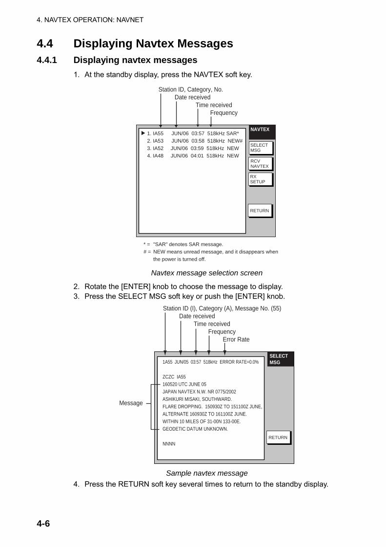
4. NAVTEX OPERATION: NAVNET
4-6
4.4 Displaying Navtex Messages 4.4.1 Displaying navtex messages
1. At the standby display, press the NAVTEX soft key.
NAVTEX
SELECTMSG
RCVNAVTEX
RETURN
RXSETUP
1. IA55 JUN/06 03:57 518kHz SAR*2. IA53 JUN/06 03:58 518kHz NEW#3. IA52 JUN/06 03:59 518kHz NEW4. IA48 JUN/06 04:01 518kHz NEW
Station ID, Category, No. Date received Time received Frequency
* ="SAR" denotes SAR message.# =NEW means unread message, and it disappears when the power is turned off.
Navtex message selection screen
2. Rotate the [ENTER] knob to choose the message to display. 3. Press the SELECT MSG soft key or push the [ENTER] knob.
RETURN
1A55 JUN/05 03:57 518kHz ERROR RATE=0.0%
ZCZC IA55160520 UTC JUNE 05JAPAN NAVTEX N.W. NR 0775/2002ASHIKURI MISAKI, SOUTHWARD.FLARE DROPPING. 150930Z TO 151100Z JUNE,ALTERNATE 160930Z TO 161100Z JUNE.WITHIN 10 MILES OF 31-00N 133-00E.GEODETIC DATUM UNKNOWN.
NNNN
Station ID (I), Category (A), Message No. (55) Date received Time received Frequency Error Rate
Message
SELECTMSG
Sample navtex message
4. Press the RETURN soft key several times to return to the standby display.

4. NAVTEX OPERATION: NAVNET
4-7
4.4.2 Remarks on navtex messages
• All navtex messages begin with “ZCZC” (navtex message ID) and end with “NNNN”. Immediately following ZCZC, the transmitting station ID, message category and message number are shown. In the example illustration at the bottom of the previous page this data is “IA55.”
I = Transmitting station’s ID A = Message category 55 = Message number
• An asterisk (*) is displayed in place of actual character when the character could not be read.
• Message number 00 contains important emergency information.
• The FAX-30 holds 130 navtex messages. When the navtex message storage capacity is exceeded, the oldest navtex message is automatically deleted to make room for the latest.

4. NAVTEX OPERATION: NAVNET
4-8
4.5 Displaying the Navtex Station List You may display the navtex stations stored in the FAX-30, as follows: 1. Press the [MENU] key to open the FAX-30 menu. 2. Press the EDIT NAVTEX STATION soft key. 3. Press the 490 kHz STATION LIST soft key or the 518 kHz STATION LIST soft
key as appropriate. The illustration below shows the nav areas for 490 kHz. NAVAREA
RETURN
NAV AREA 01 UNITED KINGDOMNAV AREA02FRANCENAV AREA 03SPAINNAV AREA 04 U.S.A.NAV AREA 05 BRAZILNAV AREA 06 ARGENTIANAV AREA 07 SOUTH AFRICANAV AREA 08 INDIANAV AREA 09 PAKISTANNAV AREA 10 AUSTRALIANEXT PAGE
EDIT
Nav areas for 490 kHz navtex stations
4. Choose nav area desired and push the [ENTER] knob. For example, choose nav area 0I of 490 kHz to show the 490 kHz station list. (To choose nav area 11 to 16, choose NEXT PAGE and push the [ENTER] knob.)
STATIONLIST
RETURN
I, U 55°02’N 001°26’W CULLERCOATSC 54°51’N 005°07’W PORTPATRICKI, T 30°35’N 001°18’W NITON
EDIT
490 kHz stations of nav area I
5. If you want to view or edit the contents of a navtex station, rotate the [ENTER] knob to choose a station and press EDIT soft key. Follow the instructions in the previous paragraph to edit a station.
6. Press the [MENU] key to return to the standby screen.

4. NAVTEX OPERATION: NAVNET
4-9
4.6 Adding Navtex Stations You may add newly established navtex stations to the navtex station list as follows: 1. Press the [MENU] key to open the FAX-30 menu. 2. Press the EDIT NAVTEX STATION soft key.
ADD NAVTEX STATION
518 kHz STATION LIST
490 kHz STATION LIST
EDITSTATION
RETURN
Edit station menu
3. Press the ADD NAVTEX STATION soft key. EDITSTATION
EDIT
SAVE
RETURN
NAV AREA 01STATION NAME _ _ _ _ _ _ _ _ _ _518 kHz STATION ID1 _518 kHz STATION ID2 _490 kHz STATION ID1 _490 kHz STATION ID2 _
LATITUDE 00°00' N
LONGITUDE 000°00' E
Edit navtex station menu
4. NAV AREA is selected; press the EDIT soft key.
NAV AREA
01
Nav area selection window
5. Choose appropriate area, referring to the navtex station map in the Appendix, and press the ENTER soft key.

4. NAVTEX OPERATION: NAVNET
4-10
6. Rotate the [ENTER] knob to choose STATION NAME and press the EDIT soft key.
STATION NAME
_ _ _ _ _ _ _ _ _ _
Station name entry window
7. Enter station name with the alphanumeric keys and trackball and then press the ENTER soft key.
8. Rotate the [ENTER] knob to choose 518 STATION ID1 or 490 STATION ID1 as appropriate and press the EDIT soft key.
518 kHz STATION ID1
_
Station ID1 entry window 9. Enter station ID (A-Z) and press the ENTER soft key. 10. If there are multiple stations, enter station ID in 518 kHz STATION ID2 or 490
kHz STATION ID2 as appropriate. 11. Rotate the [ENTER] knob to choose LATITUDE and press the EDIT soft key.
LATITUDE
00°00' N
Latitude entry window
12. Enter the latitude of the station and press the ENTER soft key. Use the [N↔S] soft key to switch from North latitude to South latitude and vice versa.
13. Rotate the [ENTER] knob to choose LONGITUDE and press the EDIT soft key. Enter longitude of the station similar to how you entered latitude. Use the [W↔E] soft key to switch from West longitude to East longitude and vice versa.
14. Press the SAVE soft key. 15. Rotate the [ENTER] knob to choose YES and then push the [ENTER] knob. 16. Press the [MENU] key to close the menu.
5-1
5. NAVTEX OPERATION: NavNet 3D, PC
5.1 About Navtex Messages
5.1.1 Message categories Navtex stations throughout the world provide mariners with weather and navigational navtex messages. These messages carry a four character header code which identifies transmitting station, category of message, and message number, numbered from 00 to 99. Message number 00 is reserved for important emergency messages. The categories of messages available in the navtex system are as below. A: Coastal navigational warning H: Loran message B: Meteorlogical warning I: Omega message C: Ice report J: Differential Omega message D: Search and Rescue Alert K: Other electronic navigator system message E: Meteorological forecast L: Navarea warnings F: Pilot message V to Y: No category allocated G: Decca message Z: QRU (no message on hand)
The user may select which message categories to receive and the stations from which to receive them.
Note 1: It is recommended to minimally receive categories A, B, D and L
because they are important for navigation. Note 2: To learn more about navtex messages, see paragraph 4.4.2.
5.1.2 Receiving navtex messages To receive navtex messages, set the receive mode for “navtex only” or “fax & navtex”, referring to paragraph 1.2.2 for the procedure.
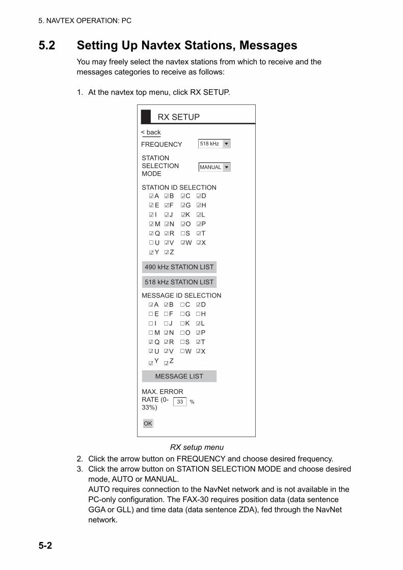
5. NAVTEX OPERATION: PC
5-2
5.2 Setting Up Navtex Stations, Messages You may freely select the navtex stations from which to receive and the messages categories to receive as follows:
1. At the navtex top menu, click RX SETUP.
< back
RX SETUP
FREQUENCY 518 kHz
STATION SELECTIONMODE
MANUAL
MAX. ERRORRATE (0-33%)
%33
OK
A B C D E F G H I J K L M N O P Q R S T U V W X Y Z
MESSAGE ID SELECTION
A B C D E F G H I J K L M N O P Q R S T U V W X Y Z
STATION ID SELECTION
490 kHz STATION LIST
518 kHz STATION LIST
MESSAGE LIST
RX setup menu
2. Click the arrow button on FREQUENCY and choose desired frequency. 3. Click the arrow button on STATION SELECTION MODE and choose desired
mode, AUTO or MANUAL. AUTO requires connection to the NavNet network and is not available in the PC-only configuration. The FAX-30 requires position data (data sentence GGA or GLL) and time data (data sentence ZDA), fed through the NavNet network.

5. NAVTEX OPERATION: PC
5-3
4. Click desired stations in STATION ID SELECTION. Check mark indicates item is selected. (If you need help with station selection, click 490 kHz STATION LIST or 518 kHz STATION LIST for details.)
5. Click desired messages in MESSAGE ID SELECTION. Check mark indicates item is selected. (If you need help with message selection, click MESSAGE LIST for details.)
6. At MAX. ERROR RATE, enter the maximum allowable error rate to use. The setting range is 0-33 (%). Any message with an error rate higher than entered here will be rejected. For a PC, enter numerical value from keyboard.
7. Click OK and then click “<back” or Back button to return to the top menu.
5.3 Displaying Navtex Messages At the navtex standby display, click the desired message number at the top of the display.
MENU
<< Top 1A55 05/30 03:57 518kHz ERROR RATE=0.0%
ZCZC IA55160520 UTC JUNE 05JAPAN NAVTEX N.W. NR 0775/2002ASHIKURI MISAKI, SOUTHWARD.FLARE DROPPING. 150930Z TO 151100Z JUNE,ALTERNATE 160930Z TO 161100Z JUNE.WITHIN 10 MILES OF 31-00N 133-00E.GEODETIC DATUM UNKNOWN.
NNNN
EDIT STATION LIST
SYSTEM SETUP
RX MODE
RX SETUP
1. 1A55 06/22 00:26 518kHz 2. 1A55 06/20 01:22 518kHz 3. 1A55 06/18 15:31 518kHz 4. 1A55 06/17 07:11 518kHz 5. 1A55 06/15 03:44 518kHz
NEXT PAGE 1/2
PREV NEXT
518kHz AUTO LAT/LON OK
SS=10 STBY
Received messages (click to display)
Use scroll bar to scroll list.
Text of message
Navtex message dataIA55: Station ID (I), Category (A),
Message No. (55)05/30: Date received03:57: Time received518kHz: FrequencyError rate
Navtex standby display

5. NAVTEX OPERATION: PC
5-4
5.4 Displaying the Navtex Station List You may display the navtex stations stored in the FAX-30 as follows: 1. At the navtex top menu, click EDIT STATION LIST. 2. Click 490 kHz STATION LIST or 518 kHz STATION LIST as appropriate. The
illustration below shows the 490 kHz list.
NAVAREA 1: UNITED KINGDOM
STATION LIST
I, U 55° 02’N 001° 26’W CULLERCOATSS 54° 51’N 005° 07’W PORTPATRICKI, T 50° 35’N 001° 18’W NITON
490kHz STATION LIST
Navtex station list 3. Pull down the arrow button on NAVAREA to choose nav area desired.
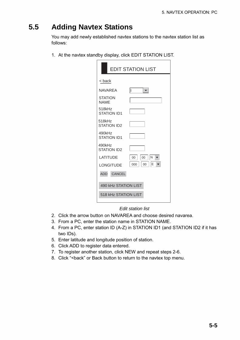
5. NAVTEX OPERATION: PC
5-5
5.5 Adding Navtex Stations You may add newly established navtex stations to the navtex station list as follows: 1. At the navtex standby display, click EDIT STATION LIST.
EDIT STATION LIST
ADD
NAVAREA
CANCEL
STATIONNAME
I
518kHzSTATION ID1
518kHzSTATION ID2
LATITUDE
LONGITUDE
490 kHz STATION LIST
518 kHz STATION LIST
< back
490kHzSTATION ID1
490kHzSTATION ID2
00 00
000 00
N
E
Edit station list
2. Click the arrow button on NAVAREA and choose desired navarea. 3. From a PC, enter the station name in STATION NAME. 4. From a PC, enter station ID (A-Z) in STATION ID1 (and STATION ID2 if it has
two IDs). 5. Enter latitude and longitude position of station. 6. Click ADD to register data entered. 7. To register another station, click NEW and repeat steps 2-6. 8. Click “<back” or Back button to return to the navtex top menu.

5. NAVTEX OPERATION: PC
5-6
5.6 Editing Navtex Stations You may edit navtex stations as follows: 1. At the navtex standby display, click EDIT STATION LIST. 2. Click 490 kHz STATION LIST or 518 kHz STATION LIST, whichever you want
to process. For example, click 490 kHz STATION LIST. 3. Click the arrow button on NAVAREA and choose desired navarea. For
example, choose UNITED KINGDOM. 4. In the station list, click the station to process. For example, click
CULLERCOATS.
SAVE CANCEL ERASE
NEW
EDIT STATION LIST
NAVAREA
STATIONNAME
518kHzSTATION ID1
518kHzSTATION ID2
LATITUDE
LONGITUDE
490 kHz STATION LIST
518 kHz STATION LIST
< back
490kHzSTATION ID1
490kHzSTATION ID2
55 02
001 26
N
W
I
CULLERCOATS
G
I
U
If you want to register a newstation from this screen, clickNEW. The screen shown onpage 5-5 appears. Follow theprocedure on page 5-5.
Edit station list 5. Edit the data. 6. Click SAVE to save data. 7. Click “<back” or Back button to return to the navtex top menu.
5. NAVTEX OPERATION: PC
5-7
5.7 Deleting Navtex Stations You may delete navtex stations from the navtex station list as below. 1. At the navtex standby display, click EDIT STATION LIST. 2. Click 490 kHz STATION LIST or 518 kHz STATION LIST, whichever you want
to process. 3. Click the arrow button on NAVAREA and choose desired navarea. 4. In the station list, click the station to process. 5. Click ERASE. 6. Click OK to erase the station, or the Cancel button to escape. 7. Click “<back” or Back button to return to the navtex top menu.

5. NAVTEX OPERATION: PC
5-8
(This page intentionally left blank.)
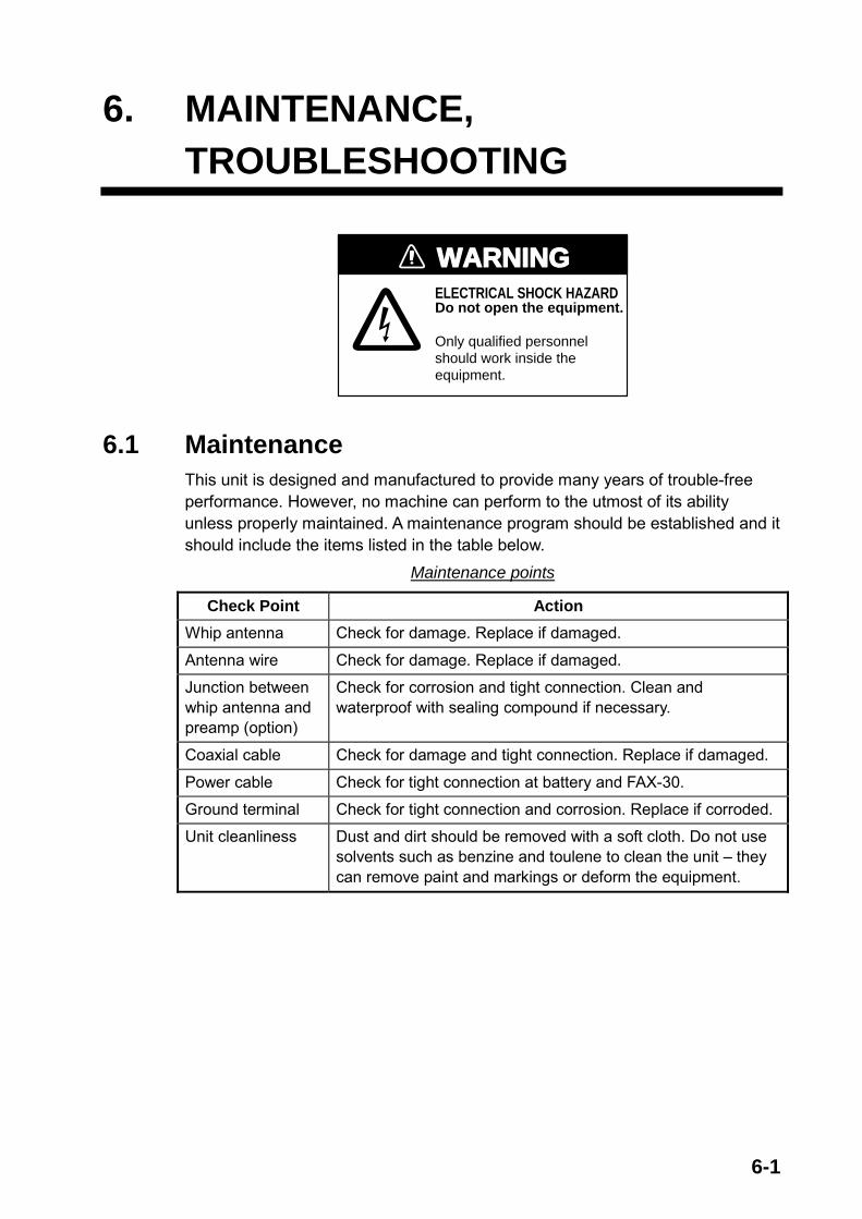
6-1
6. MAINTENANCE, TROUBLESHOOTING
WARNINGELECTRICAL SHOCK HAZARDDo not open the equipment.
Only qualified personnelshould work inside theequipment.
6.1 Maintenance This unit is designed and manufactured to provide many years of trouble-free performance. However, no machine can perform to the utmost of its ability unless properly maintained. A maintenance program should be established and it should include the items listed in the table below.
Maintenance points
Check Point Action Whip antenna Check for damage. Replace if damaged.
Antenna wire Check for damage. Replace if damaged.
Junction between whip antenna and preamp (option)
Check for corrosion and tight connection. Clean and waterproof with sealing compound if necessary.
Coaxial cable Check for damage and tight connection. Replace if damaged.
Power cable Check for tight connection at battery and FAX-30.
Ground terminal Check for tight connection and corrosion. Replace if corroded.
Unit cleanliness Dust and dirt should be removed with a soft cloth. Do not use solvents such as benzine and toulene to clean the unit – they can remove paint and markings or deform the equipment.

6. MAINTENANCE, TROUBLESHOOTING
6-2
6.2 Replacement of Fuse The 2A fuse in the power cable protects the equipment from equipment fault and reverse polarity of the ship’s mains. If the fuse blows find the cause before replacing it. If it blows again after replacement, contact your dealer for advice.
Use the proper fuse.
Use of a wrong fuse may cause serious damage to the equipmentand void the warranty.
CAUTION
6.3 Troubleshooting This section provides simple troubleshooting that the user may follow to restore normal operation.
Troubleshooting
Trouble Problem Remedy NavNet display unit freezes
• Jumbled memory • Turn the NavNet display unit off and on again.
Command from NavNet display unit not accepted
• Network not connected • Reselect the FAX mode.
Cannot read characters
• Corrupted memory • Clear memory.
Noise but no signal • Loosened antenna connector
• Coaxial cable in antenna cable is shorted or damaged.
• Fasten antenna connector.
• Replace antenna cable.
Multiple or overlapped image
• Wrong speed setting • Set correct speed. Speed may be adjusted when manually receiving an image.
Image is split. • Image is out of phase. • Set phase manually. Image is shrunk (or enlarged) vertically.
• Wrong IOC • Change IOC. IOC may be adjusted when manually receiving an image.
Image is filled with noise.
• Noise • Use the noise rejector to remove noise.
Timer schedule does not start as scheduled.
• Improper setting of schedule
• Review schedule.
Cannot access FAX-30 from PC.
• Incorrect IP address or subnet mask set on PC.
• Check setting referring to page 7-8.

6. MAINTENANCE, TROUBLESHOOTING
6-3
6.4 Diagnostics 6.4.1 NavNet
The diagnostics test displays program no. and tests the ROMs, RAM, receive ability, signal strength, signal-to-noise ratio and position data. The test results are displayed as OK or NG (No Good) for ROM, RAM, receive ability and position data. For any NG or abnormal value, contact your dealer for advice.
1. Press the [MENU] key to show the FAX-30 menu.
FAX-30
EDIT WX FAX STATION
EDIT NAVTEX STATION
FAX-30 SYSTEM SETUP
FAX-30 menu
2. Press the FAX-30 SYSTEM SETUP soft key.
SYSTEMSETUP
TEST
SIMULATION SETUP
CLEAR MEMORY
System setup menu
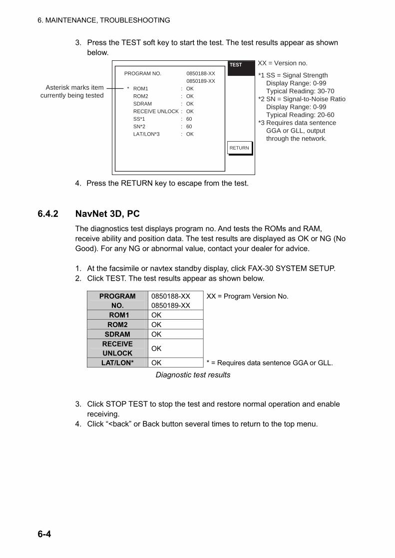
6. MAINTENANCE, TROUBLESHOOTING
6-4
3. Press the TEST soft key to start the test. The test results appear as shown below.
TEST
RETURN
PROGRAM NO. 0850188-XX0850189-XX
* ROM1 : OK ROM2 : OK SDRAM : OK RECEIVE UNLOCK : OK
SS*1 : 60SN*2 : 60
LAT/LON*3 : OK
XX = Version no.
*1 SS = Signal Strength Display Range: 0-99 Typical Reading: 30-70*2 SN = Signal-to-Noise Ratio
Display Range: 0-99 Typical Reading: 20-60*3 Requires data sentence GGA or GLL, output
through the network.
Asterisk marks itemcurrently being tested
4. Press the RETURN key to escape from the test.
6.4.2 NavNet 3D, PC
The diagnostics test displays program no. And tests the ROMs and RAM, receive ability and position data. The test results are displayed as OK or NG (No Good). For any NG or abnormal value, contact your dealer for advice.
1. At the facsimile or navtex standby display, click FAX-30 SYSTEM SETUP. 2. Click TEST. The test results appear as shown below.
PROGRAM NO.
0850188-XX 0850189-XX
XX = Program Version No.
ROM1 OK ROM2 OK
SDRAM OK RECEIVE UNLOCK OK
LAT/LON* OK * = Requires data sentence GGA or GLL.
Diagnostic test results
3. Click STOP TEST to stop the test and restore normal operation and enable receiving.
4. Click “<back” or Back button several times to return to the top menu.

6. MAINTENANCE, TROUBLESHOOTING
6-5
6.5 Clearing Data 6.5.1 NavNet
You may clear all facsimile images, navtex messages and the entire memory contents to start afresh.
1. Press the [MENU] key to open the FAX-30 menu. 2. Press the FAX-30 SYSTEM SETUP soft key. 3. Press the CLEAR MEMORY soft key.
CLEARMEMORY
EDIT
RETURN
CLEAR ALL IMAGES NOCLEAR ALL MESSAGES NOCLEAR ALL MEMORY NO
Clear memory menu
4. Rotate the [ENTER] knob to choose the item you wish to clear and press the EDIT soft key. (Clearing all memories erases all fax images, navtex messages and all setting data (for example, user-set stations)). For example, choose CLEAR ALL IMAGES and press the EDIT soft key to clear all facsimile images.
CLEAR ALL IMAGES
YES NO
Clear all images options
5. Rotate the [ENTER] knob to choose YES and push the [ENTER] knob. 6. Press the RETURN soft key to close the menu and return to the standby
display.

6. MAINTENANCE, TROUBLESHOOTING
6-6
6.5.2 NavNet 3D, PC You may clear all facsimile images, navtex messages and the entire memory contents to start afresh. 1. At the facsimile or navtex standby display, click SYSTEM SETUP. 2. Click CLEAR MEMORY.
CLEAR MEMORY
CLEAR ALL IMAGES Yes No
CLEAR ALL MESSAGES Yes No
CLEAR ALL MEMORY Yes No
OK
< back
Clear memory options
3. Click Yes for the memory(s) to clear. Note: Clearing all memories erases all fax images, navtex messages and all
setting data (for example, user-set stations). 4. Click OK. 5. You are asked if you are sure to clear the memory(s) selected. Click OK to
clear; Cancel to escape. 6. Click “<back” or Back button several times to return to the top menu.

6. MAINTENANCE, TROUBLESHOOTING
6-7
6.6 All Clear (for technicians) If the FAX-30 cannot be operated from a NavNet/NavNet 3D display unit or a PC, the reason can be stray data. Do the procedure shown below to clear the stray data and restore normal operation.
1. Turn off the FAX-30. 2. Open the cover of the FAX-30.
LED
1 2 3 4
O N
O F F
DIP Switch
U18
3. Turn ON the #1 segment of the DIP switch and then turn on the FAX-30. The LED below U18 blinks slowly when default settings have been restored. It takes about one minute to restore the settings.
4. Turn off the FAX-30. Turn off all segments of the DIP switch. (All segments must be turned off, otherwise all clear will be executed at start up.)
5. Turn on the FAX-30 and connect it to the PC that has IP address 172.31.x.x. 6. Open Internet Explorer at the PC and enter the URL http://172.31.8.1.
Confirm that the “TOP” display appears. 7. Turn off the FAX-30 and close its cover.

6. MAINTENANCE, TROUBLESHOOTING
6-8
6.7 Simulation Mode The simulation mode provides simulated operation of the equipment, using an internally generated fax image and navtex message. The fax image may be processed as desired. This mode is mainly used for exhibition purposes.
Note: All current fax images and navtex messages will be erased when
activating the simulation mode. 6.7.1 NavNet
1. At the facsimile standby display, press the [MENU] key. 2. Press the FAX-30 SYSTEM SETUP soft key. 3. Press the SIMULATION SETUP soft key.
SIMSETUP
EDIT
RETURN
WX FAX LIVENAVTEX LIVE
Simulation setup menu
4. Choose WX FAX or NAVTEX as appropriate and press the EDIT soft key. The illustration below shows the dialog box for WX FAX; the dialog box for NAVTEX is similar.
WX FAX
SIMULATIONLIVE
5. Rotate the [ENTER] knob to choose SIMULATION and press the ENTER soft
key. The fax image and navtex message will then be posted to the respective standby display.

6. MAINTENANCE, TROUBLESHOOTING
6-9
6.7.2 Navnet 3D, PC 1. At the facsimile or navtex standby display, click SYSTEM SETUP. 2. Click SIMULATION SETUP.
SIMULATION SETUP
SIMULATIONLIVE
WX FAX
SIMULATIONLIVE
NAVTEX
< back
OK
Simulation setup menu 3. Choose SIMULATION for WX FAX and/or NAVTEX as appropriate. 4. Click OK. 5. Click “<back” or Back button to return to the top. The fax image and navtex message will then be posted to respective standby display.

6. MAINTENANCE, TROUBLESHOOTING
6-10
(This page intentionally left blank.)
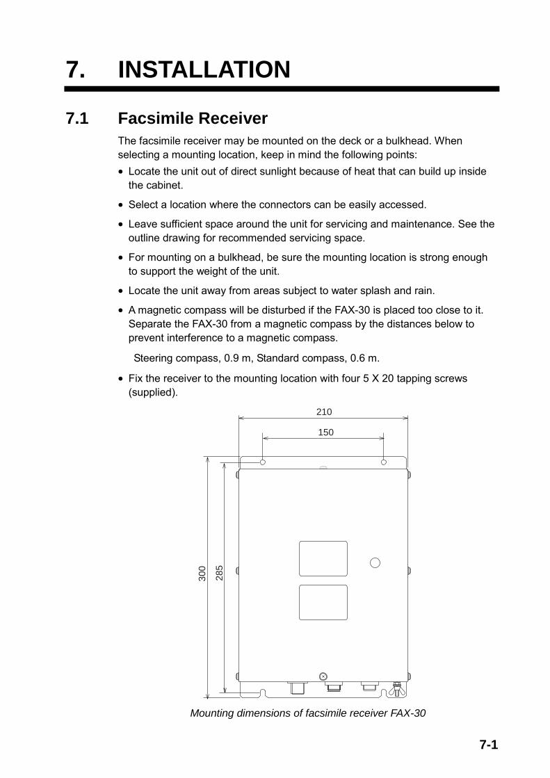
7-1
7. INSTALLATION
7.1 Facsimile Receiver The facsimile receiver may be mounted on the deck or a bulkhead. When selecting a mounting location, keep in mind the following points: • Locate the unit out of direct sunlight because of heat that can build up inside
the cabinet.
• Select a location where the connectors can be easily accessed.
• Leave sufficient space around the unit for servicing and maintenance. See the outline drawing for recommended servicing space.
• For mounting on a bulkhead, be sure the mounting location is strong enough to support the weight of the unit.
• Locate the unit away from areas subject to water splash and rain.
• A magnetic compass will be disturbed if the FAX-30 is placed too close to it. Separate the FAX-30 from a magnetic compass by the distances below to prevent interference to a magnetic compass.
Steering compass, 0.9 m, Standard compass, 0.6 m.
• Fix the receiver to the mounting location with four 5 X 20 tapping screws (supplied).
300
210
150
285
Mounting dimensions of facsimile receiver FAX-30
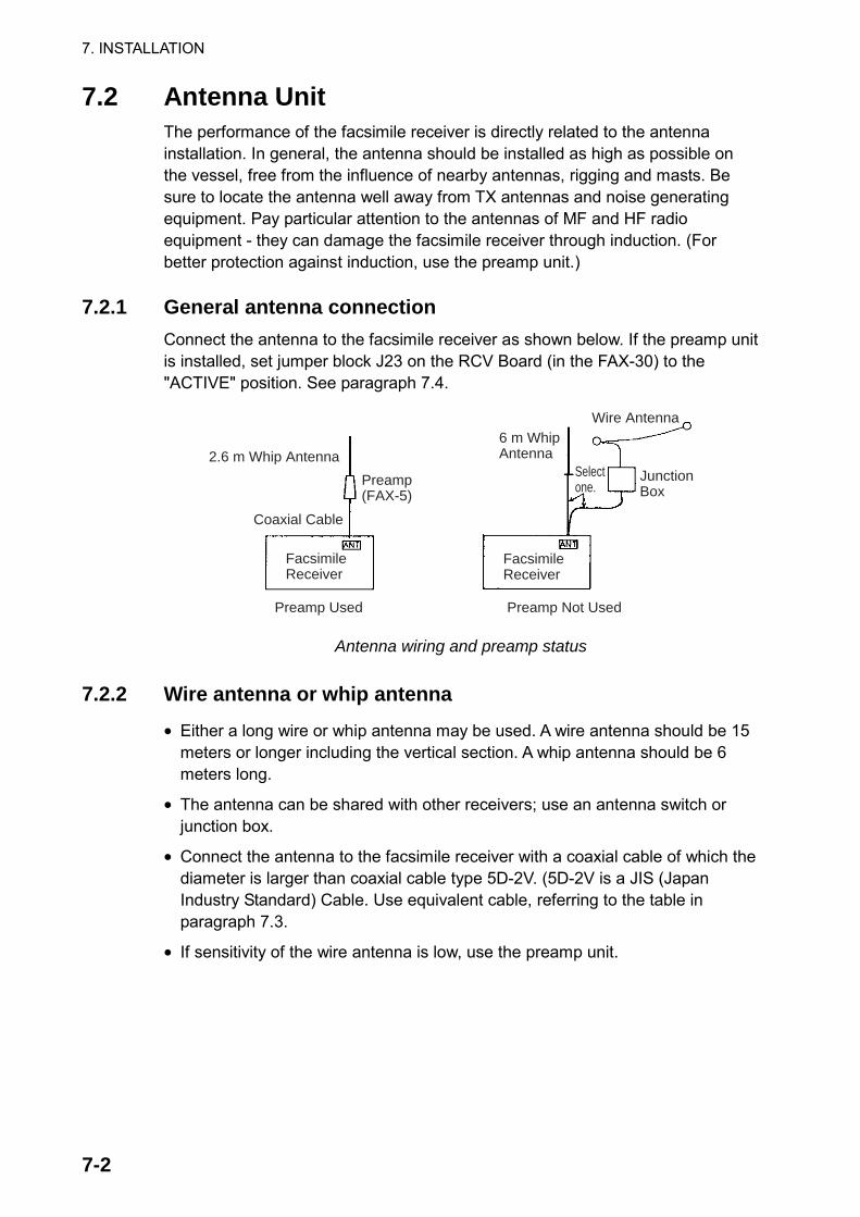
7. INSTALLATION
7-2
7.2 Antenna Unit The performance of the facsimile receiver is directly related to the antenna installation. In general, the antenna should be installed as high as possible on the vessel, free from the influence of nearby antennas, rigging and masts. Be sure to locate the antenna well away from TX antennas and noise generating equipment. Pay particular attention to the antennas of MF and HF radio equipment - they can damage the facsimile receiver through induction. (For better protection against induction, use the preamp unit.)
7.2.1 General antenna connection Connect the antenna to the facsimile receiver as shown below. If the preamp unit is installed, set jumper block J23 on the RCV Board (in the FAX-30) to the "ACTIVE" position. See paragraph 7.4.
Preamp Used Preamp Not Used
FacsimileReceiver
2.6 m Whip AntennaPreamp(FAX-5)
Coaxial Cable
FacsimileReceiver
6 m WhipAntenna
Wire Antenna
JunctionBox
Selectone.
Antenna wiring and preamp status
7.2.2 Wire antenna or whip antenna
• Either a long wire or whip antenna may be used. A wire antenna should be 15 meters or longer including the vertical section. A whip antenna should be 6 meters long.
• The antenna can be shared with other receivers; use an antenna switch or junction box.
• Connect the antenna to the facsimile receiver with a coaxial cable of which the diameter is larger than coaxial cable type 5D-2V. (5D-2V is a JIS (Japan Industry Standard) Cable. Use equivalent cable, referring to the table in paragraph 7.3.
• If sensitivity of the wire antenna is low, use the preamp unit.

7. INSTALLATION
7-3
7.2.3 Installation of preamp unit FAX-5 (option) Small boats may not afford the space to install a long wire antenna. In this case it is recommended to install the preamp unit with 2.6 meter whip antenna. The preamp unit can be installed two ways: • The base of the preamp unit is designed to accept a threaded extension of
one-inch diameter. The pitch of the thread should be 14 threads per inch. The mast itself should be no longer than 1.5 meters to prevent flexing in heavy winds.
• Attach the preamp unit to a post with stainless steel hose clamps (option).
1. Fix the preamp unit to the mounting location. 2. Screw the whip antenna onto the preamp unit. 3. If the mast is metallic, run a ground wire (local supply) between the mast and
the ground terminal on the preamp unit. 4. Waterproof the junction and other exposed metallic parts with silicone
sealant.
50Thread(14 threads/inch)
Inch Pipe
2.6 m WhipAntennaSpring
Washer
PostHoseClamp
(option) GroundSpot
Antenna Wire
Screw
Wire AntennaFixture
Preamp Unit
INCH PIPE
HOSE CLAMP (option) ON POST
WIRE ANTENNA
How to mount the preamp unit FAX-5 Note 1: An antenna wire several meters in length can be connected instead of
the whip antenna. In this case, install the wire antenna fixture (supplied with preamp unit) between the antenna wire and the preamp unit as illustrated above.
Note 2: The preamp unit is powered by the facsimile receiver. To power the preamp unit, set J23 on the RCV Board (in the FAX-30) to the "ACTIVE" position. See paragraph 7.4.

7. INSTALLATION
7-4
7.3 Wiring Four cables are connected to the facsimile receiver: antenna cable, Net Cable (or PC cable), power cable, ground wire. Connect them as shown in the figure below. For detailed information, see the interconnection diagram on page S-1.
ANT (IV-2sp)
Ground
Ground Wire*
NavNet series display unit, Hub or PCNet Cable: MJ-A6SPF0014-050C, 5 m**PC Cable: MJ-A6SPF0017-050C, 5 m
** Optional cable 1 m, 10 m, 20 m or 30 m is available.
Whip Antenna*
2.6 m Whip Antenna(option)
FAX-5Preamp(option)
AntennaSwtich*
Antenna Feeder*
Connect core only.External Conductor
Vinyl Tape
* = Local Supply
Shield
Power CableMJ-A3SPF0024-035C
12-24 VDC NETWORK
Optional cable 10, 20, 30, 40 or 50 m is available.
CoaxialCable*
Black (-)
White (+)
Switchboardbreaker
Wiring

7. INSTALLATION
7-5
Power cable
Connect the power cable (supplied) to the power source; white wire to positive [+] terminal and black wire to negative [-] terminal. Ground wire
Ground the equipment to prevent noise and interference and enable reception of weak signals. Run the ground wire (local supply) between the ground terminal on the facsimile receiver and the ship's grounding bus.
Preamp unit
Connect its coaxial cable directly to the antenna connector on the FAX-30. Note that an extension cable kit (option) is available, in lengths of 10, 20, 30, 40 and 50 m. Wire or whip antenna
A junction box or antenna switch (local supply) is required since the connection at the FAX-30 is made with a coaxial cable. Connect a feeder wire between the antenna and the junction box or antenna switch. Attach coaxial connector (option) to a 50 ohm coaxial cable as below and connect the cable between the junction box and the FAX-30. If the connector does not fit the cable, use appropriate adaptor (option).
Cable type 7C-2V, RG-8/U, RG-213/U, etc.
Cable type 5D-2V, 5C-2V, RG-5/U, 3C-2V, RG-58/U, etc.
Sheath30 mm
5 mm
2 mm
ConductorInsulator
Braidedshield
Plug assembly Contact sleeve
Cut conductor here.Solder both sides of hole.
Couplingring
Solder here.
Sheath30 mm
7 mm3.5mm
Conductor
InsulatorBraidedshield
Solder both sides of hole.
Reducer
Screw tightly. Contact sleeve
Cut conductor here.Couplingring
Solder here.3.5 mm
Attachment of antenna connector
Note: The cables 3C-2V, 5C-2V, 5D-2V and 7C-2V are JIS (Japan Industry Standard) cables. If these are not available use equivalent cables, referring to the table on the next page for specifications.

7. INSTALLATION
7-6
JIS cable specifications
Inner Conductor Insulation Outer Conductor Jacket
Braid Type
Stranding (No./mm)
Dia. (mm)
Thick (mm)
Dia (mm)
Dia./
Pitch
Dia. (mm)
Thick(mm)
Dia. (mm)
Cond. resistance (Max.) (20°C) (Ω/km)
Nominal attenuation 10 MHz (dB/km)
Capa- citance (pF/m)
Approx.mass (kg/km)
3C-2V 1/0.5 0.5 1.3 3.1 0.14/5/24 26 3.8 0.8 5.4±0.5 91.4 42 67±3 42
5C-2V 1/0.8 0.8 2.05 4.9 0.14/7/24 42 5.7 0.9 7.4±0.5 35.9 27 67±3 74
7C-2V 7/0.4 1.2 3.05 7.3 0.18//8/24 45 8.2 1.1 10.4±0.5 20.7 22 67±3 140
5D-2V 1/1.4 1.4 1.7 4.8 0.14/7/24 42 5.5 0.9 7.3±0.5 11.7 27 100±4 80
7.4 Supplying Power to the Preamp Unit The preamp unit is powered with 12 VDC power fed from the facsimile receiver. To power the preamp unit, do the following: 1. Disconnect the power cable from the FAX-30. 2. Unfasten eight screws marked with the arrows below to remove the cover.
FAX-30, top view
3. Set the jumper block J23 in the “ACT(IVE)” position. See the figure below for the “ACT” position.
MA
IN B
oard
08P
3218
RC
V B
oard
08P
3219
J23
ACT WIRE
J23
FAX-30, top view, cover removed
4. Close the cover and connect the power cable.

7. INSTALLATION
7-7
7.5 Browser, PC Settings 7.5.1 Browser settings
Set your browser as shown in the procedures below. The procedure may be different depending on browser version. Internet Explorer (Version 5.5)
1. Start up the Internet Explorer. 2. Click Tools on the menu bar. 3. Click Internet Options. 4. General is selected; click “Settings” at “Temporary Internet files.” 5. Click the radio button “Every visit to the page” at “Check for newer versions
of stored pages.” 6. Click OK. 7. Click Security tab. 8. Click Custom Level button. 9. At the item Scripting, click Enable for both “Active scripting” and “Scripting of
Java Applets.” 10. Click OK. 11. Click Connections tab. 12. Click “Never dial a connection”. 13. Click LAN Settings button. 14. Uncheck “Use a proxy server” at “Proxy server.” 15. Click OK. 16. Click OK again. Netscape Navigator (Version 4.78)
1. Start up the Netscape Navigator. 2. Click the Edit menu. 3. Click Preferences. 4. Open the Advanced menu. 5. Check “Automatically load images and other data types,” “Enable Java,”
“Enable Java script” and “Enable style sheets.” 6. Click “Cache” at Advanced. 7. Choose “Every time” in “Page in cache is compared to page on
network.” 8. Click “Proxies” at Advanced. 9. Choose “Direct connection to internet.” 10. Click OK.

7. INSTALLATION
7-8
7.5.2 PC settings The PC communicates with the FAX-30 via Internet protocol TCP/IP. Therefore, set IP address on the PC as below. 1. Start up the PC and open the Control Panel folder. 2. Open the Network and Dial-up Connections folder. 3. Double-click Local Area Connection. 4. Click Properties. 5. Check Internet Protocol (TCP/IP). 6. Click Properties. 7. Choose “Use the following IP address.” 8. Set the IP address for 172.31.100.100. 9. Set the Subnet mask for 255.255.0.0.
FACSIMILE RECEIVERFAX-30
HUB*PC
IP Address: 172.31.8.1 Subnet Mask: 255.255.0.0
IP Address:172.31.100.100
PCIP Address:172.31.100.101* = HUB is not required to connect single PC.
IP address
10. Click OK. 11. Click OK. 12. Click Close button. 13. Turn the PC off and on again. 14. Start up the browser. 15. Enter the FAX-30’s URL: http://172.31.8.1 and press the [Enter] key. The facsimile receiver top display should appear. If it does not appear, recheck above settings.
FACSIMILE RECEIVERFAX-30
WX FAX NAVTEXLOGOUT
Facsimile receiver top display

AP-1
APPENDIX
Facsimile Stations Facsimile station map
ZO
NE
2
ZO
NE
5
ZO
NE
4
ZO
NE
6
ZO
NE
8
ZO
NE
7
ZO
NE
1
ZO
NE
2
ZO
NE
3
Location of facsimile stations

APPENDIX
AP-2
Facsimile station list (by zone)
2
Tok
yoT
okyo
Tok
yoT
okyo
Tok
yoB
eijin
gB
eijin
gSh
angh
aiT
aipe
iSe
oul
JAPA
NJA
PAN
JAPA
NV
ia M
AL
AY
SIA
JAPA
NC
HIN
AC
HIN
AC
HIN
AT
AIW
AN
KO
RE
A
JMH
JMJ
JJC
9MG
*JF
A3S
DB
AF
BD
FB
MF
HLL
AU
X
0 1 3 4 5 6 7 8 9
STA
-T
ION
CA
LLS
IGN
TR
AN
SM
ITT
ED
FR
OM
NO
RT
H P
AC
IFIC
OC
EA
N
WE
STE
RN
PA
RT
ZO
NE
1
4 5 6 7 8 9
Cas
abla
nca
Fort
de
Fran
ce
Puer
to B
relg
rano
Rio
de
Jane
iro
Ori
nda
Bue
nos
Air
esC
asey
CM
IRL
FR
EI
CN
UR
LM
AR
AM
BIO
Val
para
iso
CU
BA
MA
RT
INIQ
UE
AR
GE
NT
INA
BR
ASI
LB
RA
SIL
AR
GE
NT
INA
AN
TA
RC
TIC
ASo
uth
Shet
land
Is.
AN
TA
RC
TIC
CH
ILE
CLX
FF
PG
YALO
RP
WZ
PR
O *
LRO
VLM
CA
NLS
BC
BV
0 1 2 3
STA
-T
ION
CA
LLS
IGN
TR
AN
SM
ITT
ED
FR
OM
SOU
TH
AT
LA
NT
IC O
CE
AN
ZO
NE
4
Aus
tral
ia w
est
Aus
tral
ia e
ast
Auc
klan
dG
uam
Gua
mN
ew D
elhi
Teh
eran
Nai
robi
CA
PE N
AV
AL
Den
is M
ET
EO
Mol
odez
hnay
a
AU
STR
AL
IAA
UST
RA
LIA
NE
W Z
EA
LA
ND
Via
AU
STR
AL
IAV
ia J
APA
NIN
DIA
IRA
NK
EN
YA
SOU
TH
AFR
ICA
MA
UR
ITIU
SR
USS
IA
VM
WV
MC
ZK
LF
NP
N
ATA
EP
D5Y
EZ
SJ
HX
PR
UZ
U
0 1 2 3 4 5 6 7 8 9
STA
-T
ION
CA
LLS
IGN
TR
AN
SM
ITT
ED
FR
OM
SOU
TH
PA
CIF
IC O
CE
AN
,IN
DIA
N O
CE
AN
, PE
RSI
AN
GU
LF
ZO
NE
3G
uam
Sang
lay
Poin
tB
angk
okPe
arl H
arbo
rH
onol
ulu
Kod
iak,
Ala
ska
Esq
uim
alt
Cal
ifor
nia
Neb
rask
a
MA
RIA
NA
IS.
PHIL
IPPI
NE
ST
HA
ILA
ND
USA
USA
USA
CA
NA
DA
USA
USA
NP
NN
PO
HS
WN
PM
KV
MN
OJ
CK
NN
MC
ELK
AU
X
0 1 2 3 4 5 6 7 8 9
STA
-T
ION
CA
LLS
IGN
TR
AN
SM
ITT
ED
FR
OM
NO
RT
H P
AC
IFIC
OC
EA
N
EA
STE
RN
PA
RT
ZO
NE
2
New
Orl
eans
Bos
ton
Bos
ton
Hal
ifax
RE
SOL
UT
ESk
amle
baek
USA
USA
USA
CA
NA
DA
CA
NA
DA
GR
EE
NL
AN
D
NM
GN
MF
NIK
CF
HV
FF
OX
TA
UX
AU
XA
UX
AU
X
0 1 2 3 4 5 6 7 8 9
STA
-T
ION
CA
LLS
IGN
TR
AN
SM
ITT
ED
FR
OM
NO
RT
H A
TL
AN
TIC
OC
EA
NW
EST
ER
N P
AR
TZ
ON
E
5
Rom
eA
then
sB
eogr
ade
Sofi
aA
nkar
aT
ashi
kent
1T
ashi
kent
2C
airo
Jedd
ahT
bilis
i
ITA
LY
GR
EE
CE
YU
GO
SLA
VIA
BU
LG
AR
IAT
UR
KE
YU
ZB
EK
IST
AN
UZ
BE
KIS
TA
NE
GY
PTSA
UD
I A
RA
BIA
GR
UZ
IJA
IMB
SV
JY
ZZ
LZJ2
YM
AR
BV
RB
XS
UU
JED
RIS
0 1 2 3 4 5 6 7 8 9
STA
-T
ION
CA
LLS
IGN
TR
AN
SM
ITT
ED
FR
OM
ME
DIT
ER
RA
NE
AN
SE
AZ
ON
E
8Off
enba
ch
Off
enba
ch
Cop
enha
gen
Prah
a-M
odra
nyN
orrk
opin
gM
urm
ansk
Hel
sink
iV
aasa
GE
RM
AN
Y
GE
RM
AN
Y
DE
NM
AR
KC
ZE
CH
OSL
OV
AK
IASW
ED
EN
RU
SSIA
FIN
LA
ND
FIN
LA
ND
DC
FD
DK
DD
H *
OX
TO
LTS
MA
RB
WO
FAO
FW
NO
VA
UX
0 1 2 3 4 5 6 7 8 9
STA
-T
ION
CA
LLS
IGN
TR
AN
SM
ITT
ED
FR
OM
NO
RT
H A
TL
AN
TIC
OC
EA
NN
OR
TH
ER
N P
AR
TZ
ON
E
7
Nor
thw
ood
Rot
aM
adri
dK
enito
raD
akar
UK
SPA
INSP
AIN
MO
RO
CC
OSE
NE
GA
L
GYA
AO
KM
AD
NH
Y6V
UA
UX
AU
XA
UX
AU
XA
UX
0 1 2 3 4 5 6 7 8 9
STA
-T
ION
CA
LLS
IGN
TR
AN
SM
ITT
ED
FR
OM
NO
RT
H A
TL
AN
TIC
OC
EA
NE
AST
ER
N P
AR
TZ
ON
E
6
FAC
SIM
ILE
STA
TIO
N L
IST
ZO
NE
[0]
and
[9]
are
allo
cate
d fo
r pr
ivat
e ch
anne
ls.
(10
chan
nels
eac
h fo
r 10
sta
tions
)*:
Cal
lsig
n no
t dis
play
ed.
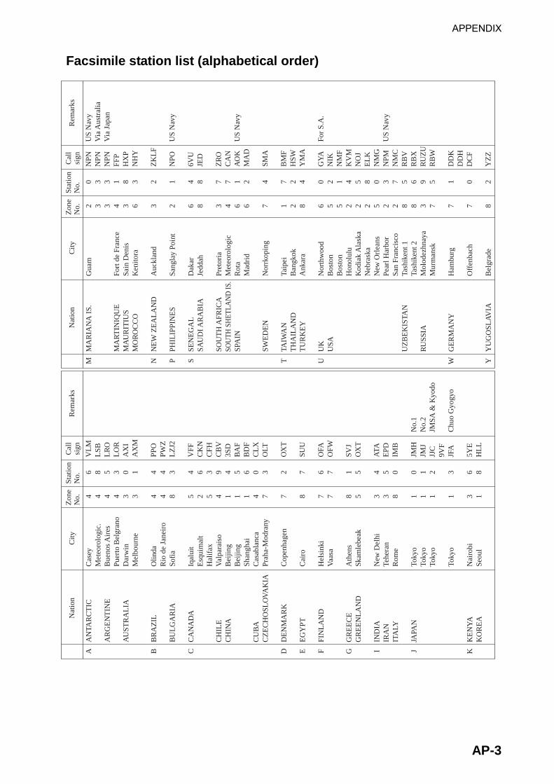
APPENDIX
AP-3
Facsimile station list (alphabetical order) N
atio
nC
ityR
emar
ksZ
one
No.
Stat
ion
No.
Cal
lsi
gn
AN
TAR
CT
IC
AR
GE
NT
INE
AU
STR
AL
IA
BR
AZ
IL
BU
LG
AR
IA
CA
NA
DA
CH
ILE
CH
INA
CU
BA
CZ
EC
HO
SLO
VA
KIA
DE
NM
AR
K
EG
YPT
FIN
LA
ND
GR
EE
CE
GR
EE
NL
AN
D
IND
IAIR
AN
ITA
LY
JAPA
N
KE
NY
AK
OR
EA
Cas
eyM
eteo
rolo
gic.
Bue
nos
Air
esPu
erto
Bel
gran
oD
arw
inM
elbo
urne
Olin
daR
io d
e Ja
neir
oSo
fia
Iqal
uit
Esq
uim
alt
Hal
ifax
Val
para
iso
Bei
jing
Bei
jing
Shan
ghai
Cas
abla
nca
Prah
a-M
odra
ny
Cop
enha
gen
Cai
ro
Hel
sink
iV
aasa
Ath
ens
Skam
lebe
ak
New
Del
hiTe
hera
nR
ome
Toky
oTo
kyo
Toky
o
Toky
o
Nai
robi
Seou
l
A B C D E F G I J K
4 4 4 4 3 3 4 4 8 5 2 5 4 1 1 1 4 7 7 8 7 7 8 5 3 3 8 1 1 1 1 3 1
6 8 5 3 0 1 4 4 3 4 6 3 9 4 5 6 0 3 2 7 6 7 1 5 4 5 0 0 1 2 3 6 8
VL
ML
SBL
RO
LO
RA
XI
AX
M
PPO
PWZ
LZ
J2
VFF
CK
NC
FHC
BV
3SD
BA
FB
DF
CL
XO
LT
OX
T
SUU
OFA
OFW
SVJ
OX
T
ATA
EPD
IMB
JMH
JMJ
JJC
9VF
JFA
5YE
HL
L
No.
1N
o.2
JMSA
& K
yodo
Chu
o G
yogy
o
Nat
ion
City
Rem
arks
Zon
eN
o.St
atio
nN
o.C
all
sign
MA
RIA
NA
IS.
MA
RT
INIQ
UE
MA
UR
ITIU
SM
OR
OC
CO
NE
W Z
EA
LA
ND
PHIL
IPPI
NE
S
SEN
EG
AL
SAU
DI A
RA
BIA
SOU
TH
AFR
ICA
SOU
TH S
HET
LAN
D IS
.SP
AIN
SWE
DE
N
TAIW
AN
TH
AIL
AN
DT
UR
KE
Y
UK
USA
UZ
BE
KIS
TAN
RU
SSIA
GE
RM
AN
Y
YU
GO
SLA
VIA
Gua
m
Fort
de
Fran
ceSa
in D
enis
Ken
itora
Auc
klan
d
Sang
lay
Poin
t
Dak
arJe
ddah
Pret
oria
Met
eoro
logi
cR
ota
Mad
rid
Nor
rkop
ing
Taip
eiB
angk
okA
nkar
a
Nor
thw
ood
Bos
ton
Bos
ton
Hon
olul
uK
odia
k A
lask
aN
ebra
ska
New
Orl
eans
Pear
l Har
bor
San
Fran
cisc
oTa
shik
ent 1
Tash
iken
t 2M
olod
ezhn
aya
Mur
man
sk
Ham
burg
Off
enba
ch
Bel
grad
e
M N P S T U W Y
2 3 3 4 3 6 3 2 6 8 3 4 6 6 7 1 2 8 6 5 5 2 2 2 5 2 2 8 8 3 7 7 7 8
0 3 3 1 8 3 2 1 4 8 7 7 1 2 4 7 2 4 0 2 1 4 5 8 0 3 7 5 6 9 5 1 0 2
NPN
NPN
NPN
FFP
HX
PN
HY
ZK
LF
NPO
6VU
JED
ZR
OC
AN
AO
KM
AD
SMA
BM
FH
SWY
MA
GY
AN
IKN
MF
KV
MN
OJ
EL
KN
MG
NPM
NM
CR
BV
RB
XR
UZ
UR
BW
DD
KD
DH
DC
F
YZ
Z
US
Nav
yV
ia A
ustr
alia
Via
Jap
an
US
Nav
y
US
Nav
y
For
S.A
.
US
Nav
y

APPENDIX
AP-4
Navtex Stations Navtex stations map
Location of navtex stations

APPENDIX
AP-5
Navtex stations list
NAV
area Country Station Latitude Longitude
Freq.
(kHz)
Area
(nm)
Station
ID Broadcast schedule (UTC)
I V 0330, 0730, 1130, 1530, 1930, 2330
518
T 0310, 0710, 1110, 1510, 1910, 2310
Belgium Oostende 51° 11’ N 002° 48’ E
490
55
B 0010, 0410, 0810, 1210, 1610, 2010
Estonia Tallinn 59° 28’ N 024° 21’ E 518 250 U 0320, 0720, 1120, 1520, 1920, 2320
Foroyar (Denmark) Torshavn 62° 01’ N 006° 48’ W 518 250 D 0030, 0430, 0830, 1230, 1630, 2030
518 S 0300, 0700, 1100, 1500, 1900, 2300
Germany Hamburg 53° 40’ N 009° 48’ E
490
400
L 0150, 0550, 0950, 1350, 1750, 2150
518 X 0350, 0750, 1150, 1550, 1950, 2350
Grindavik 63° 47’ N 022° 31’ W
490
550
K 0140, 0540, 0940, 1340, 1740, 2140
518 R 0250, 0650, 1050, 1450, 1850, 2250
Reykjavik 64° 05’ N 021° 51’ W
490
550
R 0320, 0720, 1120, 1520, 1920, 2320
Iceland
Saudanes 66° 11’ N 018° 57’ W 490 550 E 0040, 0440, 0840, 1240, 1640, 2040
Valencia 51° 56’ N 010° 21’ W 518 400 W 0340, 0740, 1140, 1540, 1940, 2340
Ireland
Malin Head 55° 22’ N 007° 21’ W 518 400 Q 0240, 0640, 1040, 1440, 1840, 2240
Netherlands Den Helder 52° 06’ N 004° 15’ E 518 110 P 0230, 0630, 1030, 1430, 1830, 2230
Bodo 67° 16’ N 014° 23’ E 518 450 B 0010, 0410, 0810, 1210, 1610, 2010
Rogaland 58° 48’ N 005° 34’ E 518 450 L 0150, 0550, 0950, 1350, 1750, 2150
Vardoe Radio 70° 22’ N 031° 06’ E 518 450 C 0020, 0420, 0820, 1220, 1620, 2020
Svalbard 78° 04’ N 013° 38’ E 518 450 A 0000, 0400, 0800, 1200, 1600, 2000
Orlandet 63° 40’ N 009° 33’ E 518 450 N 0210, 0610, 1010, 1410, 1810, 2210
Norway
Tjome (Jeloya) 59° 26’ N 010° 34’ E 518 450 M 2000, 0600, 1000, 1400, 1800, 2200
Arkhangelsk 64° 51’ N 040° 17’ E 518 300 L 0150, 0550, 0950, 1350, 1750, 2150
Russia
Murmansk 68° 46’ N 032° 58’ E 518 300 K 0140, 0540, 0940, 1340, 1740, 2140
Bjuroklubb 64° 28’ N 021° 35’ E 518 300 H 0110, 0510, 0910, 1310, 1710, 2110
Gislovshammar 55° 29’ N 014° 19’ E 518 300 J 0130, 0530, 0930, 1330, 1730, 2130
Sweden
Grimeton 57° 06’ N 012° 23’ E 518 300 I 0120, 0520, 0920, 1320, 1720, 2120
518 G 0100, 0500, 0900, 1300, 1700, 2100
Cullercoats 55° 02’ N 001° 26’ W
490
270
U 0320, 0720, 1120, 1520, 1920, 2320
518 O 0220, 0620, 1020, 1420, 1820, 2220
Portpatrick 54° 51’ N 005° 07’ W
490
270
C 0020, 0420, 0820, 1220, 1620, 2020
E 0040, 0440, 0840, 1240, 1640, 2040
518
K 0140, 0540, 0940, 1340, 1740, 2140
I 0120, 0520, 0920, 1320, 1720, 2120
United Kingdom
Niton 50° 35’ N 001° 18’ W
490
270
T 0310, 0710, 1110, 1510, 1910, 2310
(Continued on next page)
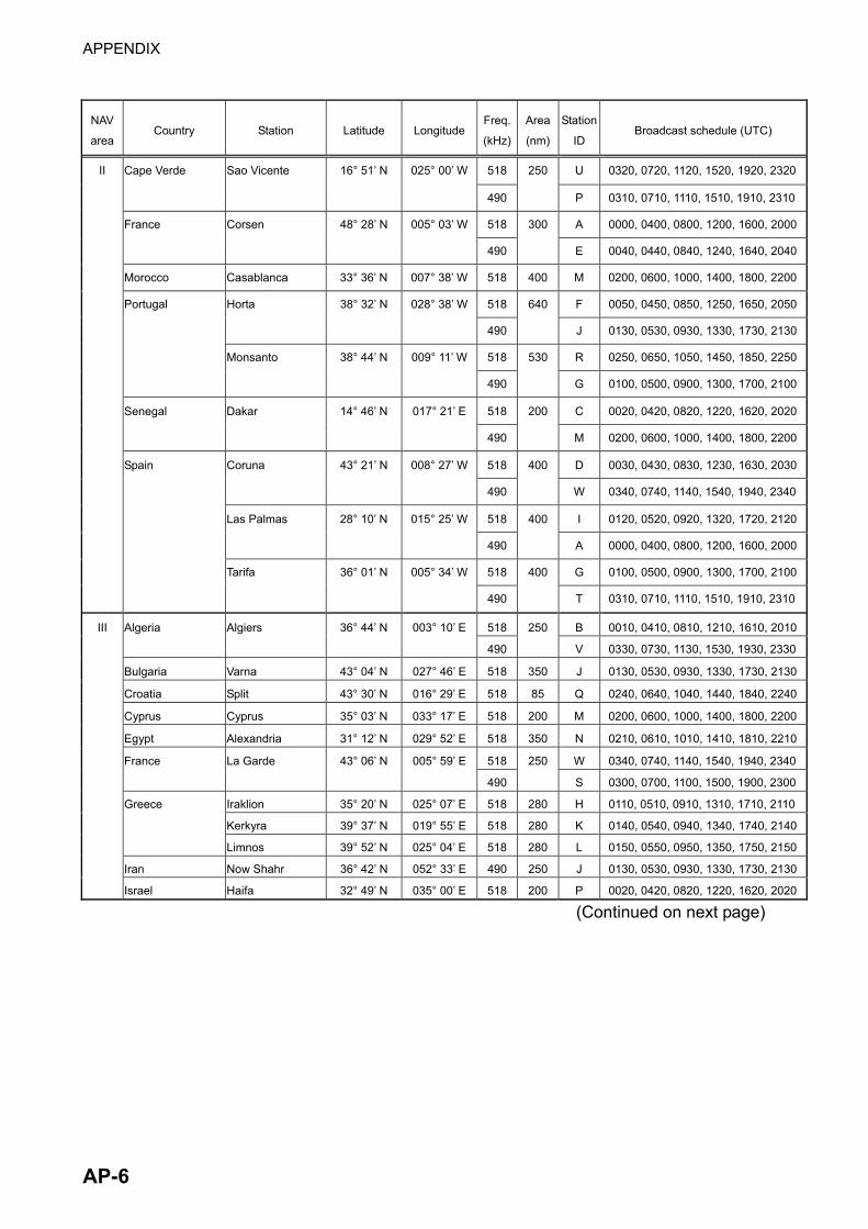
APPENDIX
AP-6
NAV
area Country Station Latitude Longitude
Freq.
(kHz)
Area
(nm)
Station
ID Broadcast schedule (UTC)
II 518 U 0320, 0720, 1120, 1520, 1920, 2320
Cape Verde Sao Vicente 16° 51’ N 025° 00’ W
490
250
P 0310, 0710, 1110, 1510, 1910, 2310
518 A 0000, 0400, 0800, 1200, 1600, 2000
France Corsen 48° 28’ N 005° 03’ W
490
300
E 0040, 0440, 0840, 1240, 1640, 2040
Morocco Casablanca 33° 36’ N 007° 38’ W 518 400 M 0200, 0600, 1000, 1400, 1800, 2200
518 F 0050, 0450, 0850, 1250, 1650, 2050
Horta 38° 32’ N 028° 38’ W
490
640
J 0130, 0530, 0930, 1330, 1730, 2130
518 R 0250, 0650, 1050, 1450, 1850, 2250
Portugal
Monsanto 38° 44’ N 009° 11’ W
490
530
G 0100, 0500, 0900, 1300, 1700, 2100
518 C 0020, 0420, 0820, 1220, 1620, 2020
Senegal Dakar 14° 46’ N 017° 21’ E
490
200
M 0200, 0600, 1000, 1400, 1800, 2200
518 D 0030, 0430, 0830, 1230, 1630, 2030
Coruna 43° 21’ N 008° 27’ W
490
400
W 0340, 0740, 1140, 1540, 1940, 2340
518 I 0120, 0520, 0920, 1320, 1720, 2120
Las Palmas 28° 10’ N 015° 25’ W
490
400
A 0000, 0400, 0800, 1200, 1600, 2000
518 G 0100, 0500, 0900, 1300, 1700, 2100
Spain
Tarifa 36° 01’ N 005° 34’ W
490
400
T 0310, 0710, 1110, 1510, 1910, 2310
518 B 0010, 0410, 0810, 1210, 1610, 2010III Algeria Algiers 36° 44’ N 003° 10’ E
490
250
V 0330, 0730, 1130, 1530, 1930, 2330
Bulgaria Varna 43° 04’ N 027° 46’ E 518 350 J 0130, 0530, 0930, 1330, 1730, 2130
Croatia Split 43° 30’ N 016° 29’ E 518 85 Q 0240, 0640, 1040, 1440, 1840, 2240
Cyprus Cyprus 35° 03’ N 033° 17’ E 518 200 M 0200, 0600, 1000, 1400, 1800, 2200
Egypt Alexandria 31° 12’ N 029° 52’ E 518 350 N 0210, 0610, 1010, 1410, 1810, 2210
518 W 0340, 0740, 1140, 1540, 1940, 2340
France La Garde 43° 06’ N 005° 59’ E
490
250
S 0300, 0700, 1100, 1500, 1900, 2300
Iraklion 35° 20’ N 025° 07’ E 518 280 H 0110, 0510, 0910, 1310, 1710, 2110
Kerkyra 39° 37’ N 019° 55’ E 518 280 K 0140, 0540, 0940, 1340, 1740, 2140
Greece
Limnos 39° 52’ N 025° 04’ E 518 280 L 0150, 0550, 0950, 1350, 1750, 2150
Iran Now Shahr 36° 42’ N 052° 33’ E 490 250 J 0130, 0530, 0930, 1330, 1730, 2130
Israel Haifa 32° 49’ N 035° 00’ E 518 200 P 0020, 0420, 0820, 1220, 1620, 2020
(Continued on next page)
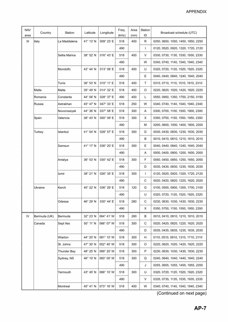
APPENDIX
AP-7
NAV
area Country Station Latitude Longitude
Freq.
(kHz)
Area
(nm)
Station
ID Broadcast schedule (UTC)
III 518 R 0250, 0650, 1050, 1450, 1850, 2250
La Maddalena 41° 13’ N 009° 23’ E
490
400
I 0120, 0520, 0920, 1320, 1720, 2120
518 V 0330, 0730, 1130, 1530, 1930, 2330
Sellia Marina 38° 52’ N 016° 43’ E
490
400
W 0340, 0740, 1140, 1540, 1940, 2340
518 U 0320, 0720, 1120, 1520, 1920, 2320
Mondolfo 43° 44’ N 013° 08’ E
490
400
E 0040, 0440, 0840, 1240, 1640, 2040
Italy
Tunis 36° 53’ N 010° 11’ E 518 400 T 0310, 0710, 1110, 1510, 1910, 2310
Malta Malta 35° 49’ N 014° 32’ E 518 400 O 0220, 0620, 1020, 1420, 1820, 2220
Romania Constanta 44° 06’ N 028° 37’ E 490 400 L 0550, 0950, 1350, 1750, 2150, 0150
Astrakhan 45° 47’ N 047° 33’ E 518 250 W 0340, 0740, 1140, 1540, 1940, 2340
Russia
Novorossiysk 44° 36’ N 037° 58’ E 518 300 A 0300, 0700, 1100, 1500, 1900, 2300
518 X 0350, 0750, 1150, 1550, 1950, 2350
Spain Valencia 38° 43’ N 000° 09’ E
490
300
M 0200, 0600, 1000, 1400, 1800, 2200
518 D 0030, 0430, 0830, 1230, 1630, 2030
Istanbul 41° 04’ N 028° 57’ E
490
300
B 0010, 0410, 0810, 1210, 1610, 2010
518 E 0040, 0440, 0840, 1240, 1640, 2040
Samsun 41° 17’ N 036° 20’ E
490
300
A 0000, 0400, 0800, 1200, 1600, 2000
518 F 0050, 0450, 0850, 1250, 1650, 2050
Antalya 36° 53’ N 030° 42’ E
490
300
D 0030, 0430, 0830, 1230, 1630, 2030
518 I 0120, 0520, 0920, 1320, 1720, 2120
Turkey
Izmir 38° 21’ N 026° 35’ E
490
300
C 0020, 0420, 0820, 1220, 1620, 2020
518 G 0100, 0500, 0900, 1300, 1700, 2100
Kerch 45° 22’ N 036° 29’ E
490
120
U 0320, 0720, 1120, 1520, 1920, 2320
518 C 0230, 0630, 1030, 1430, 1830, 2230
Ukraine
Odessa 46° 29’ N 030° 44’ E
490
280
X 0350, 0750, 1150, 1550, 1950, 2350
IV Bermuda (UK) Bermuda 32° 23’ N 064° 41’ W 518 280 B 0010, 0410, 0810, 1210, 1610, 2010
518 C 0020, 0420, 0820, 1220, 1620, 2020
Sept Iles 50° 11’ N 066° 07’ W
490
300
D 0035, 0435, 0835, 1235, 1635, 2035
Wiarton 44° 20’ N 081° 10’ W 518 300 H 0110, 0510, 0910, 1310, 1710, 2110
St. Johns 47° 30’ N 052° 40’ W 518 300 O 0220, 0620, 1020, 1420, 1820, 2220
Thunder Bay 48° 25’ N 089° 20’ W 518 300 P 0230, 0630, 1030, 1430, 1830, 2230
518 Q 0240, 0640, 1040, 1440, 1840, 2240
Sydney, NS 46° 10’ N 060° 00’ W
490
300
J 0255, 0655, 1055, 1455, 1855, 2255
518 U 0320, 0720, 1120, 1520, 1920, 2320
Yarmouth 43° 45’ N 066° 10’ W
490
300
V 0335, 0735, 1135, 1535, 1935, 2335
Canada
Montreal 45° 41’ N 073° 16’ W 518 400 W 0340, 0740, 1140, 1540, 1940, 2340
(Continued on next page)
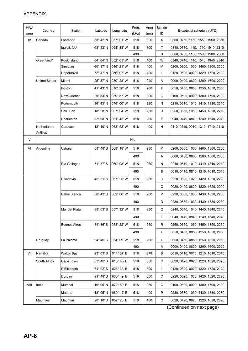
APPENDIX
AP-8
NAV
area Country Station Latitude Longitude
Freq.
(kHz)
Area
(nm)
Station
ID Broadcast schedule (UTC)
IV Labrador 53° 42’ N 057° 01’ W 518 300 X 0350, 0750, 1150, 1550, 1950, 2350
518 T 0310, 0710, 1110, 1510, 1910, 2310
Canada
Iqaluit, NU 63° 43’ N 068° 33’ W
490
300
S 0300, 0700, 1100, 1500, 1900, 2300
Kook Island 64° 04’ N 052° 01’ W 518 400 W 0340, 0740, 1140, 1540, 1940, 2340
Simiutaq 60° 37’ N 046° 21’ W 518 400 M 0200, 0600, 1000, 1400, 1800, 2200
Greenland*
Uppernavik 72° 47’ N 056° 07’ W 518 400 I 0120, 0520, 0920, 1320, 1720, 2120
Miami 25° 37’ N 080° 23’ W 518 240 A 0000, 0400, 0800, 1200, 1600, 2000
Boston 41° 43’ N 070° 30’ W 518 200 F 0050, 0450, 0850, 1250, 1650, 2050
New Orleans 29° 53’ N 089° 57’ W 518 200 G 0100, 0500, 0900, 1300, 1700, 2100
Portsmouth 36° 43’ N 076° 00’ W 518 280 N 0210, 0610, 1010, 1410, 1810, 2210
San Juan 18° 28’ N 067° 04’ W 518 200 R 0250, 0650, 1050, 1450, 1850, 2250
United States
Charleston 32° 08’ N 081° 42’ W 518 200 E 0040, 0440, 0840, 1240, 1640, 2040
Netherlands
Antilles
Curacao 12° 10’ N 068° 52’ W 518 400 H 0110, 0510, 0910, 1310, 1710, 2110
V NIL
VI 518 M 0200, 0600, 1000, 1400, 1800, 2200
Ushaia 54° 48’ S 068° 18’ W
490
280
A 0000, 0400, 0800, 1200, 1600, 2000
518 N 0210, 0610, 1010, 1410, 1810, 2210
Rio Gallegos 51° 37’ S 069° 03’ W
490
280
B 0010, 0410, 0810, 1210, 1610, 2010
518 O 0220, 0620, 1020, 1420, 1820, 2220
Rivadavia 45° 51’ S 067° 25’ W
490
280
C 0020, 0420, 0820, 1220, 1620, 2020
518 P 0230, 0630, 1030, 1430, 1830, 2230
Bahia Blanca 38° 43’ S 062° 06’ W
490
280
D 0230, 0630, 1030, 1430, 1830, 2230
518 Q 0240, 0640, 1040, 1440, 1840, 2240
Mar del Plata 38° 03’ S 057° 32’ W
490
280
E 0040, 0440, 0840, 1240, 1640, 2040
518 R 0250, 0650, 1050, 1450, 1850, 2250
Argentina
Buenos Aires 34° 36’ S 058° 22’ W
490
560
F 0050, 0450, 0850, 1250, 1650, 2050
518 F 0050, 0450, 0850, 1250, 1650, 2050 Uruguay La Paloma 34° 40’ S 054° 09’ W
490
280
A 0000, 0400, 0800, 1200, 1600, 2000
VII Namibia Walvis Bay 23° 03’ S 014° 37’ E 518 378 B 0010, 0410, 0810, 1210, 1610, 2010
Cape Town 33° 40’ S 018° 43’ E 518 300 C 0020, 0420, 0820, 1220, 1620, 2020
P Elizabeth 34° 02’ S 025° 33’ E 518 300 I 0120, 0520, 0920, 1320, 1720, 2120
South Africa
Durban 29° 48’ S 030° 49’ E 518 300 O 0220, 0620, 1020, 1420, 1820, 2220
VIII Mumbai 19° 05’ N 072° 50’ E 518 250 G 0100, 0500, 0900, 1300, 1700, 2100
India
Madras 13° 05’ N 080° 17’ E 518 400 P 0230, 0630, 1030, 1430, 1830, 2230
Mauritius Mauritius 20° 10’ S 057° 28’ E 518 400 C 0020, 0420, 0820, 1220, 1620, 2020
(Continued on next page)
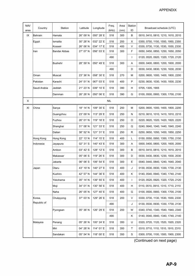
APPENDIX
AP-9
NAV
area Country Station Latitude Longitude
Freq.
(kHz)
Area
(nm)
Station
ID Broadcast schedule (UTC)
IX Bahrain Hamala 26° 09’ N 050° 28’ E 518 300 B 0010, 0410, 0810, 1210, 1610, 2010
Ismailia 30° 28’ N 032° 22’ E 518 200 X 0350, 0750, 1150, 1550, 1950, 2350
Egypt
Kosseir 26° 06’ N 034° 17’ E 518 400 V 0330, 0730, 1130, 1530, 1930, 2330
518 F 0050, 0450, 0850, 1250, 1650, 2050
Bandar Abbas 27° 07’ N 056° 03’ E
490
300
I 0120, 0520, 0920, 1320, 1720, 2120
518 A 0000, 0400, 0800, 1200, 1600, 2000
Iran
Bushehr 28° 59’ N 050° 49’ E
490
300
D 0030, 0430, 0830, 1230, 1630, 2030
Oman Muscat 23° 36’ N 058° 30’ E 518 270 M 0200, 0600, 1000, 1400, 1800, 2200
Pakistan Karachi 24° 51’ N 067° 03’ E 518 400 P 0230, 0630, 1030, 1430, 1830, 2230
Jeddah 21° 23’ N 039° 10’ E 518 390 H 0705, 1305, 1905
Saudi Arabia
Damman 26° 26’ N 050° 06’ E 518 390 G 0100, 0500, 0900, 1300, 1700, 2100
X NIL
XI Sanya 18° 14’ N 109° 30’ E 518 250 M 0200, 0600, 1000, 1400, 1800, 2200
Guangzhou 23° 09’ N 113° 29’ E 518 250 N 0210, 0610, 1010, 1410, 1810, 2210
Fuzhou 26° 01’ N 119° 18’ E 518 250 O 0220, 0620, 1020, 1420, 1820, 2220
Shanghai 31° 08’ N 121° 33’ E 518 250 Q 0240, 0640, 1040, 1440, 1840, 2240
China
Dalian 38° 52’ N 121° 31’ E 518 250 R 0250, 0650, 1050, 1450, 1850, 2250
Hong Kong Hong Kong 22° 13’ N 114° 15’ E 518 400 L 0150, 0550, 0950, 1350, 1750, 2150
Jayapura 02° 31’ S 140° 43’ E 518 300 A 0000, 0400, 0800, 1200, 1600, 2000
Ambon 03° 42’ S 128° 12’ E 518 300 B 0010, 0410, 0810, 1210, 1610, 2010
Makassar 05° 06’ S 119° 26’ E 518 300 D 0030, 0430, 0830, 1230, 1830, 2030
Indonesia
Jakarta 06° 06’ S 106° 54’ E 518 300 E 0040, 0440, 0840, 1240, 1640, 2040
Otaru 43° 19’ N 140° 27’ E 518 400 J 0130, 0530, 0930, 1330, 1730, 2130
Kushiro 42° 57’ N 144° 36’ E 518 400 K 0140, 0540, 0940, 1340, 1740, 2140
Yokohama 35° 14’ N 139° 55’ E 518 400 I 0120, 0520, 0920, 1320, 1720, 2120
Moji 34° 01’ N 130° 56’ E 518 400 H 0110, 0510, 0910, 1310, 1710, 2110
Japan
Naha 26° 05’ N 127° 40’ E 518 400 G 0100, 0500, 0900, 1300, 1700, 2100
518 V 0330, 0730, 1130, 1530, 1930, 2330
Chukpyong 37° 03’ N 129° 26’ E
490
200
J 0130, 0530, 0930, 1330, 1730, 2130
518 W 0340, 0740, 1340, 1540, 1940, 2340
Korea,
Republic of
Pyongsan 35° 36’ N 126° 29’ E
490
200
K 0140, 0540, 0940, 1340, 1740, 2140
Penang 05° 26’ N 100° 24’ E 518 350 U 0320, 0720, 1120, 1520, 1920, 2320
Miri 04° 28’ N 114° 01’ E 518 350 T 0310, 0710, 1110, 1510, 1910, 2310
Malaysia
Sandakan 05° 54’ N 118° 00’ E 518 350 S 0300, 0700, 1100, 1500, 1900, 2300
(Continued on next page)

APPENDIX
AP-10
NAV
area Country Station Latitude Longitude
Freq.
(kHz)
Area
(nm)
Station
ID Broadcast schedule (UTC)
XI 518 E 0040, 0440, 0840, 1240, 1840, 2240
Hamhung 39° 50’ N 127° 41’ E
490
200
B 0010, 0410, 0810, 1210, 1610, 2210
518 D 0030, 0430, 0830, 1230, 1830, 2230
North Korea
Pyongyang 38° 55’ N 125° 43’ E
490
200
A 0000, 0400, 0800, 1200, 1600, 2200
Davao 07° 04’ N 125° 36’ E 518 400 K 0140, 0540, 0940, 1340, 1740, 2140
Manila 14° 35’ N 121° 03’ E 518 400 J 0130, 0530, 0930, 1330, 1730, 2130
Philippines
P Princesa 09° 44’ N 118° 43’ E 518 400 I 0120, 0520, 0920, 1320, 1720, 2120
Singapore Singapore 01° 21’ N 103° 59’ E 518 400 C 0020, 0420, 0820, 1220, 1620, 2020
Kaohsiung 22° 29’ N 120° 25’ E 518 216 P 0230, 0630, 1030, 1430, 1830, 2230
Taiwan
Chilung 25° 09’ N 121° 44’ E 518 400 P 0230, 0630, 1030, 1430, 1830, 2230
Thailand Bangkok 13° 43’ N 100° 34’ E 518 200 F 0050, 0450, 0850, 1250
United States Guam 13° 29’ N 144° 50’ E 518 100 V 0330, 0730, 1130, 1530, 1930, 2330
Ho Chi Minh 10° 23’ N 107° 08’ E 518 400 X 0350, 0750, 1150, 1550, 1950, 2350
Haiphong 20° 44’ N 106° 44’ E 490 W 0340, 0740, 1140, 1540, 1940, 2340
Vietnam
Danang 16° 05’ N 108° 13’ E 518 400 K 0140, 0540, 0940, 1340, 1740, 2140
XII Prince Rupert 54° 20’ N 130° 20’ W 518 300 D 0030, 0430, 0830, 1230, 1630, 2030
Canada
Tofino 48° 55’ N 125° 35’ W 518 300 H 0110, 0510, 0910, 1310, 1710, 2110
518 L 0150, 0550, 0950, 1350, 1750, 2150
Ecuador Ayora 00° 45’ S 090° 19’ W
490
400
A 0000, 0400, 0800, 1200, 1600, 2000
San Francisco 37° 55’ N 122° 44’ W 518 350 C 0020, 0420, 0820, 1220, 1620, 2020
Kodiak (EAST) J 0130, 0530, 0930, 1330, 1730, 2130
Kodiak (WEST)
57° 46’ N 152° 34’ W 518 200
X 0350, 0750, 1150, 1550, 1950, 2250
Honolulu 21° 22’ N 158° 09’ W 518 350 O 0220, 0620, 1020, 1420, 1820, 2220
Cambria 35° 31’ N 121° 03’ W 518 350 Q 0240, 0640, 1040, 1440, 1840, 2240
United States
Astoria 46° 10’ N 123° 49’ W 518 216 W 0340, 0740, 1140, 1540, 1940, 2240
XIII Beringovskiy 63° 03’ N 179° 20’ E 518 400 E 0040, 0440, 0840, 1240, 1640, 2040
Kholmsk 47° 02’ N 142° 03’ E 518 300 B 0010, 0410, 0810, 1210, 1610, 2010
Magadan 59° 41’ N 150° 09’ E 518 120 D 0030, 0430, 0830, 1230, 1630, 2030
Okhotsk 59° 22’ N 143° 12’ E 518 300 G 0100, 0500, 0900, 1300, 1700, 2100
Petropavlovsk 53° 00’ N 158° 40’ E 518 300 C 0020, 0420, 0820, 1220, 1620, 2020
Provideniya 64° 40’ N 173° 10’ W 518 400 F 0050, 0450, 0850, 1250, 1650, 2050
Tiksi 71° 38’ N 128° 50’ E 518 300 Q 0240, 0640, 1040, 1440, 1840, 2240
Russia
Vladivostok 43° 23’ N 131° 54’ E 518 230 A 0000, 0400, 0800, 1200, 1600, 2000
XIV NIL
(Continued on next page)

APPENDIX
AP-11
NAV
area Country Station Latitude Longitude
Freq.
(kHz)
Area
(nm)
Station
ID Broadcast schedule (UTC)
A 0400, 1200, 2000 XV Antofagasta 23° 40’ S 070° 25’ W 518 300
H 0000, 0800, 1600
B 0410, 1210, 2010 Valparaiso 32° 48’ S 071° 29’ W 518 300
I 0010, 0810, 1610
C 0420, 1220, 2020 Talcahuano 36° 42’ S 073° 06’ W 518 300
J 0020, 0820, 1620
D 0430, 1230, 2030 Puerto Montt 41° 30’ S 072° 58’ W 518 300
K 0030, 0830, 1630
E 0440, 1240, 2040 Punta Arenas 53° 09’ S 070° 58’ W 518 300
L 0040, 0840, 1640
F 0450, 1250, 2050
Chile
Isla d Pascua 27° 09’ S 109° 25’ W 518 300
G 0050, 0850, 1650
XVI Ecuador Guayaquil 02° 17’ S 079° 52’ W 518 400 M 0200, 0600, 1000, 1400, 1800, 2200
Paita 05° 05’ S 081° 07’ W 518 200 S 0300, 0700, 1100, 1500, 1900, 2300
Callao 12° 03’ S 077° 09’ W 518 200 U 0320, 0720, 1120, 1520, 1920, 2320
Peru
Mollendo 17° 01’ S 072° 01’ W 518 200 W 0340, 0740, 1140, 1540, 1940, 2340
XVII NIL
*: These stations are newly added. Register them to the NAVTEX station list (see section 4.6).

APPENDIX
AP-12
Menu Tree NavNet menu tree
WX FAXsoft key
SELECT IMAGE EDIT IMAGE PHASE (00 - 40, 0)SYNC (-50 - +50, 0)NOISE REJECT (OFF, LOW, MEDIUM, HIGH)EDIT COLOR COLOR MONOCHROME
GRAY SCALE BLUE-RED WHITE-BLUE PINK-BLACK REVERSE IMAGE (NORMAL, REVERSE)
ZOOM IN (ZOOM OUT)ROTATE (CW and CCW soft keys)LOCK/ERASE IMAGE (LOCK IMAGE and ERASE IMAGE soft keys)
RCV WX CH SETUP ZONE (0-9, 1)FAX STA (0-9, 0)
CH (0-9, AUTO; 0)FREQ
TIMER SETUP START TIMER PROG LIST
START RX (288/60, 288/90, 288/120, 288/180, 288/240, 576/60, 576/90, 576/120, 576/180, 576/240)
STOP RX
NAVTEXsoft key
SELECT MSG
RX SETUP FREQUENCY (490 kHz, 518 kHz)STA. SELECTION MODE (MANUAL, AUTO)STATION SELECTION (A-Z, all stations ON)MESSAGE SELECTION (A-Z, A-E, L, V)MAX ERROR RATE (0-33) (%)ALARM (SAR MSG) (ON, OFF)ALARM (WARNING MSG) (ON, OFF)
RX MODE soft key (WX FAX, NAVTEX, FAX (TIMER) & NAV) RX NOTICE soft key (ON, OFF)
MODESETUPsoft key
RCV NAVTEX

APPENDIX
AP-13
EDIT WX ZONE (0-9, 0)FAX STATION (0-9, 0)STATION CHANNEL (0-9, AUTO; 0)
REVERSE IMAGE (NORMAL, REVERSE)FREQUENCY (80.0 kHz)CALL SIGN (PRV)STATION NAME
EDIT ADD NAVTEX STATIONNAVTEX NAV AREA (1-16, 1)STATION STATION NAME
518 kHz STATION ID1 518 kHz STATION ID2 490 kHz STATION ID1 490 kHz STATION ID2
STATION ID2 LATITUDE LONGITUDE
518 kHz STATION LIST 490 kHz STATION LIST
MENUKey
FAX-30 TESTSYSTEM SIMULATION SETUP SETUP CLEAR MEMORY (ICLEAR ALL IMAGES, CLEAR ALL MESSAGES, CLEAR ALL MEMORY)

APPENDIX
AP-14
PC, NavNet 3D menu tree ZONE STATION CHANNEL FREQUENCY
CHANNEL SETUP
TIMER SETUP (START, STOP ; PROGRAM LIST)
EDIT STATIONLIST
ZONE STATION CHANNEL REVERSE IMAGE (NORMAL, REVERSE) FREQUENCY CALL SIGN STATION NAME
SYSTEMSETUP
TESTSIMULATION SETUP
CLEAR MEMORY
WX FAX (SIMULATION, LIVE)NAVTEX (SIMULATION, LIVE)CLEAR ALL IMAGES (YES, NO)CLEAR ALL MESSAGES (YES, NO)CLEAR ALL MEMORY (YES, NO)
RX MODE (WX FAX, NAVTEX, FAX(TIMER) & NAVTEX)

APPENDIX
AP-15
FREQUENCY (490 kHz, 518 kHz)STATION SELECTION MODE (MANUAL, AUTO)
STATION ID SELECTION (A-Z, all stations ON) MESSAGE ID SELECTION (A-Z, A-E, L, V) MAX. ERROR RATE (0-33%, 33)
RX SETUP
NAV AREA (I-XVI, I) STATION NAME 518kHz STATION ID1 518kHz STATION ID2 490kHz STATION ID1 490kHz STATION ID2 LATITUDE LONGITUDE 490 kHz STATION LIST 518 kHz STATION LIST
EDIT STATION LIST
SYSTEM SETUP (Same items as on the facsimile menu.)
RX MODE (Same items as on the facsimile menu.)

APPENDIX
AP-16
This page is intentionally left blank.

FURUNO FAX-30
SP - 1 E6260S01B
SPECIFICATIONS OF FACSIMILE RECEIVER FAX-30
1 GENERAL 1.1 Frequency
FAX LF 80-160 kHz
MF/HF 2-25 MHz
NAVTEX 490 kHz, 518 kHz
1.2 Number of channels 1000
1.3 Receiving system Double super heterodyne
1.4 Class of emission FAX: F3C/J3C, NAVTEX: F1B
1.5 Network interface Ethernet 10 BASE-T TCP/IP
2 POWER SUPPLY 12-24 VDC: 1.0-0.5 A
3 ENVIRONMENTAL CONDITION 3.1 Ambient temperature -15°C to +55°C
3.2 Relative humidity 95% or less at +40°C
3.3 Degree of protection IPX2
3.4 Vibration IEC 60945
4 COATING COLOR N3.0
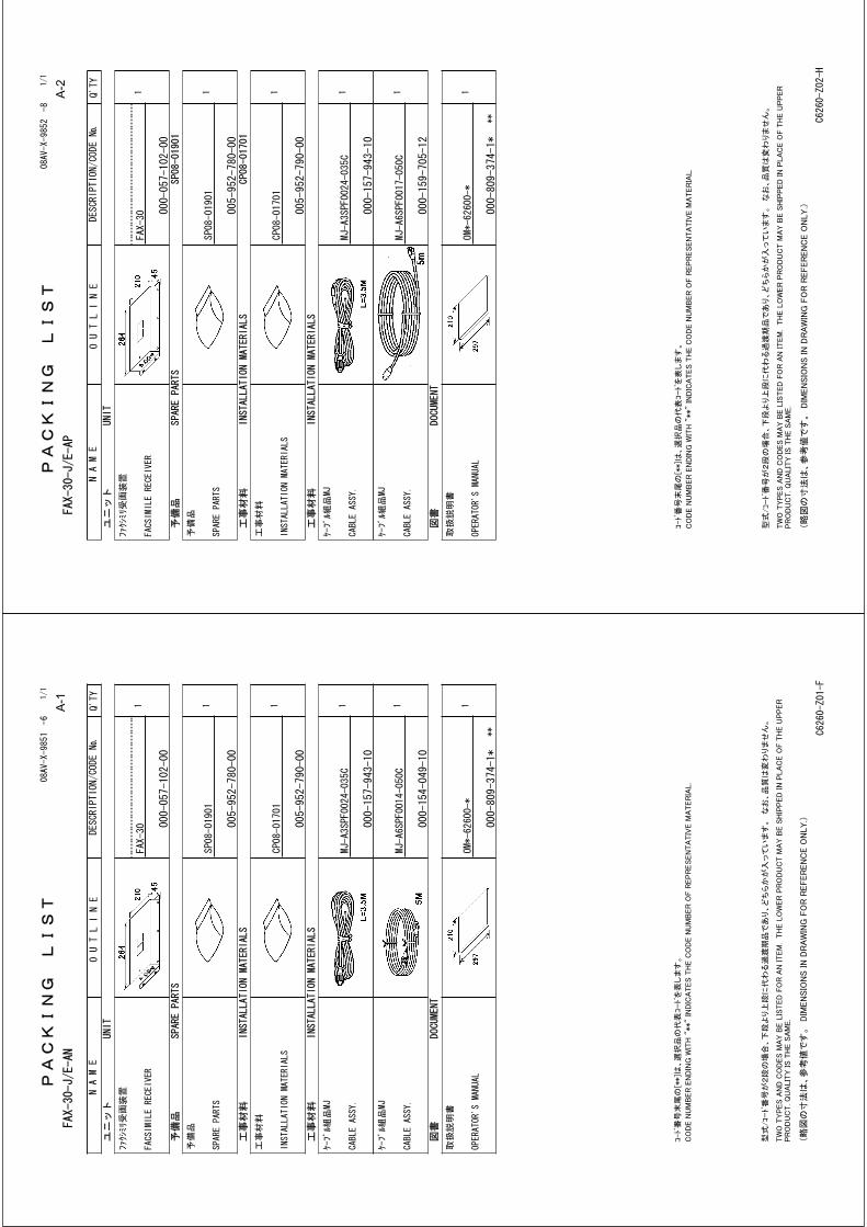
A-2
A-1
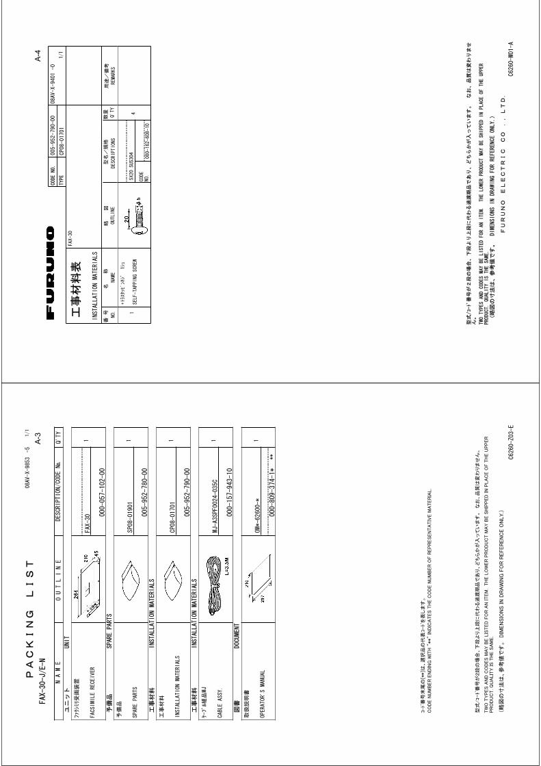
A-4
A-3

A-5

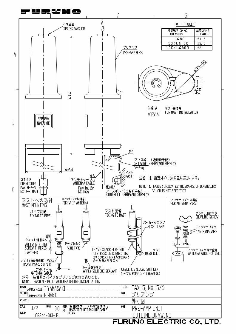
ynishiyama
テキストボックス
25/Mar/2011 Y.NISHIYAMA
emiyoshi
テキストボックス
D-2
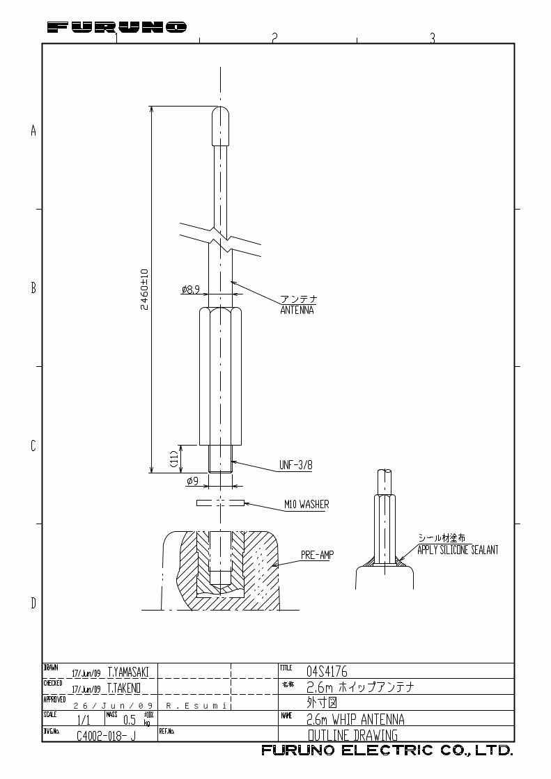
26/Jun/09 R.Esumi
emiyoshi
テキストボックス
D-3

24
3
A
1
B CDRAWN
CHECKED
APPROVED
DWG.No.
MASS
SCALE
TITLE
NAME
名称
FACS
IMIL
ERE
CEIV
ER
ファ
クシ
ミリ
受画
装置
FAX-
30
INTE
RCON
NECT
ION
DIAG
RAM
相互
結線
図
M-P-3
ANT
M-P-7
2.6m
ホイ
ップア
ンテ
ナWHIP
ANTENNA
PREAMP
プリ
アン
プ
FAX-5
*2
IV-2sq.*1
FUSE
2A
0V
POWER
J32
3
シロ
WHT
クロ
BLK
(-)
(+)
1 212-24
VDC
MJ-A3SPF
(08S0358)
MJ-A3SPF0024-035C,3.5m,φ
10
FACSIMILERECEIVER
ファクシミリ受画装置
FAX-
30
J31
ETHERNET
651 2 3 4
SHIELD
E_RD_N
E_RD_P
E_TD_N
E_TD_P
NC
MJ-A6SPF
*2
*1
RG-10/UY
1m
FMA-1
3D-2V,10/20/30/40/50mM-P-3
延長ケーブ
ルキ
ット
EXTENSIONCABLEKIT
*2
OP04-2
3D-2V,15m,φ
6
*3
*3
*1
*3
GND
*1
IV-8sq.
*2
1m
FMA-1
M-P-7
*1
*1
MJ-A6SPF0017-050C,5m,φ
6
MJ-A6SPF0014-050C,5m,φ6
MJ-A6SPF0014-010C/100C/200C/300C,
1/10/20/30m(*2)
NAVNETEQUIP.
NAVNET機
*1.
SHIPYARD
SUPPLY.
NOTE
*2.
OPTION.
*3.
FITTEDAT
FACTORY.
*1)造
船所手
配。
注記
*2)オ
プショ
ン。
*3)工
場にて
取付済
み。
T.YAMASAKI
H.MAKI
8/Nov/2012
8/Nov/2012
C6260-C01-G
REF.No.08-001-3146-3
*1
HUB/PC
NAVNET3D
9/Nov/2012 Y.NISHIYAMA
emiyoshi
テキストボックス
S-1

IN-1
INDEX A Automatic fax receiving
starting (NavNet) .....................................2-1 starting (NavNet 3D, PC).........................3-1 stopping (NavNet) ...................................2-4 stopping (NavNet 3D, PC).......................3-1
C CCW soft key.............................................2-16 CH SETUP soft key.....................................2-2 CHANNEL soft key ......................................2-3 CLEAR ALL soft key ..................................2-11 Clearing data
NavNet.....................................................6-5 (NavNet 3D, PC.......................................6-6
COLOR soft key ........................................2-15 Controls (NavNet)........................................1-1 CW soft key ...............................................2-16
D Diagnostics
NavNet.....................................................6-3 (NavNet 3D, PC.......................................6-4
DISP key......................................................1-3
E EDIT COLOR soft key ...............................2-15 ERASE IMAGE soft key ............................2-16 Erasing fax images
NavNet...................................................2-16 NavNet 3D, PC........................................3-9 preventing erasure of (NavNet).............2-17 preventing erasure of (PC)....................3-10
F Fax channel addition
NavNet...................................................2-18 (NavNet 3D, PC.....................................3-11
Fax images displaying (NavNet) ...............................2-12 displaying (PC) ........................................3-5 erasing (NavNet) ...................................2-16 erasing ((NavNet 3D,PC) ........................3-9 erasure, preventing of (NavNet)............2-17 erasure, preventin of (NavNet 3D, PC) .3-10 processing (NavNet)..............................2-13
processing (PC) ...................................... 3-5 saving (NavNet 3D, PC) ......................... 3-9
FAX mode (NavNet).................................... 1-3 Fax station list .......................................... AP-2 Fax station map........................................ AP-1
I Image color
NavNet .................................................. 2-15 NavNet 3D, PC ....................................... 3-8
Image format NavNet .................................................. 2-15 NavNet 3D, PC ....................................... 3-8
L LOCK IMAGE soft key .............................. 2-17 LOCK/ERASE soft key.............................. 2-16 Logout ......................................................... 1-8
M Maintenance................................................ 6-1 Manual fax receiving (NavNet)
starting .................................................... 2-5 stopping................................................... 2-6
Menu tree ................................................. AP-9
N Navtex messages
categories................................................ 4-1 displaying (NavNet)................................. 4-6 displaying (NavNet 3D, PC).................... 5-3 previewing (NavNet) ............................... 4-5
Navtex setup NavNet .................................................... 4-2 (NavNet 3D, PC) ..................................... 5-2
Navtex stations list of ..................................................... AP-5 map of .................................................. AP-4
Navtex stations addition (NavNet) .................................... 4-9 addition (NavNet 3D, PC) ....................... 5-5 editing (NavNet 3D, PC........................... 4-9 editing (NavNet 3D, PC) ......................... 5-6 erasing (NavNet 3D, PC PC) .................. 5-7 list (NavNet) ............................................ 4-8 list NavNet 3D, PC (PC) ......................... 5-4
NOISE REJECT soft key .......................... 2-14
INDEX
IN-2
Noise rejection NavNet...................................................2-14 NavNet 3D, PC........................................3-7
P Phase
NavNet...................................................2-13 NavNet 3D, PC........................................3-6
PHASE soft key.........................................2-13 PROG LIST soft key..................................2-11
R RCV NAVTEX soft key ................................4-5 Receive mode
NavNet.....................................................1-4 NavNet 3D, PC........................................1-8
Receive notification (NavNet)......................1-5 REV IMAGE soft key .................................2-15 ROTATE soft key .......................................2-16 Rotating fax images
NavNet...................................................2-16 NavNet 3D, PC........................................3-9
RX MODE soft key ......................................1-4 RX NOTICE soft key ...................................1-5
S Saving fax images (PC)...............................3-9 SELECT IMAGE soft key ..........................2-12 Simulation mode
NavNet.....................................................6-8 NavNet 3D, PC........................................6-9
Standby display NavNet 3D, PC........................................1-6
STATION soft key ........................................2-2 STOP RX soft key .......................................2-4 Sync
NavNet...................................................2-14 NavNet 3D, PC........................................3-7
SYNC soft key ...........................................2-14 System configuration..................................... ix
T Timer operation
clearing all programs (NavNet)............. 2-11 clearing all programs (NavNet 3D, PC) .. 3-4 setting (NavNet) ...................................... 2-7 setting (PC) ............................................. 3-2 turning on/off all program (NavNet) ...... 2-11 turning on/off all programs
(NavNet 3D, PC)................................. 3-4 turning on/off specific
programs (NavNet) ........................... 2-11 turning on/off specific programs
(NavNet 3D, PC)................................. 3-4 TIMER SETUP soft key ............................ 2-11 TIMER soft key............................................ 2-7
Z ZONE soft key............................................. 2-2 Zoom
NavNet .................................................. 2-16 NavNet 3D, PC ....................................... 3-9
ZOOM IN soft key ..................................... 2-16 ZOOM OUT soft key ................................. 2-16

FURUNO Worldwide Warranty for Pleasure Boats (Except North America)
This warranty is valid for products manufactured by Furuno Electric Co. (hereafter FURUNO) and installed on a pleasure boat. Any web based purchases that are imported into other countries by anyone other than a FURUNO certified dealer may not comply with local standards. FURUNO strongly recommends against importing these products from international websites as the imported product may not work correctly and may interfere with other electronic devices. The imported product may also be in breach of the local laws and mandated technical requirements. Products imported into other countries as described previously shall not be eligible for local warranty service. For products purchased outside of your country please contact the national distributor of Furuno products in the country where purchased. This warranty is in addition to the customer´s statutory legal rights.
1. Terms and Conditions of Warranty
FURUNO guarantees that each new FURUNO product is the result of quality materials and workmanship. The warranty is valid for a period of 2 years (24 months) from the date of the invoice, or the date of commissioning of the product by the installing certified dealer.
2. FURUNO Standard Warranty The FURUNO standard warranty covers spare parts and labour costs associated with a warranty claim, provided that the product is returned to a FURUNO national distributor by prepaid carrier. The FURUNO standard warranty includes: Repair at a FURUNO national distributor All spare parts for the repair Cost for economical shipment to customer
3. FURUNO Onboard Warranty
If the product was installed/commissioned and registered by a certified FURUNO dealer, the customer has the right to the onboard warranty. The FURUNO onboard warranty includes
• Free shipping of the necessary parts • Labour: Normal working hours only • Travel time: Up to a maximum of two (2) hours • Travel distance: Up to a maximum of one hundred
and sixty (160) KM by car for the complete journey
4. Warranty Registration For the Standard Warranty - presentation of product with serial number (8 digits serial number, 1234-5678) is sufficient. Otherwise, the invoice with serial number, name and stamp of the dealer and date of purchase is shown. For the Onboard Warranty your FURUNO certified dealer will take care of all registrations.
5. Warranty Claims For the Standard Warranty - simply send the defective product together with the invoice to a FURUNO national distributor. For the Onboard Warranty – contact a FURUNO national distributor or a certified dealer. Give the product´s serial number and describe the problem as accurately as possible.
Warranty repairs carried out by companies/persons other than a FURUNO national distributor or a certified dealer is not covered by this warranty.
6. Warranty Limitations
When a claim is made, FURUNO has a right to choose whether to repair the product or replace it. The FURUNO warranty is only valid if the product was correctly installed and used. Therefore, it is necessary for the customer to comply with the instructions in the handbook. Problems which result from not complying with the instruction manual are not covered by the warranty. FURUNO is not liable for any damage caused to the vessel by using a FURUNO product. The following are excluded from this warranty: a. Second-hand product b. Underwater unit such as transducer and hull unit c. Routine maintenance, alignment and calibration
services. d. Replacement of consumable parts such as fuses,
lamps, recording papers, drive belts, cables, protective covers and batteries.
e. Magnetron and MIC with more than 1000 transmitting
hours or older than 12 months, whichever comes first. f. Costs associated with the replacement of a transducer
(e.g. Crane, docking or diver etc.). g. Sea trial, test and evaluation or other demonstrations. h. Products repaired or altered by anyone other than the
FURUNO national distributor or an authorized dealer. i. Products on which the serial number is altered,
defaced or removed. j. Problems resulting from an accident, negligence,
misuse, improper installation, vandalism or water penetration.
k. Damage resulting from a force majeure or other natural
catastrophe or calamity. l. Damage from shipping or transit. m. Software updates, except when deemed necessary
and warrantable by FURUNO. n. Overtime, extra labour outside of normal hours such as
weekend/holiday, and travel costs above the 160 KM allowance
o. Operator familiarization and orientation. FURUNO Electric Company, March 1, 2011

FURUNO Warranty for North America
FURUNO U.S.A., Limited Warranty provides a twenty-four (24) months LABOR and twenty-four (24) months PARTS warranty on products from the date of installation or purchase by the original owner. Products or components that are represented as being waterproof are guaranteed to be waterproof only for, and within the limits, of the warranty period stated above. The warranty start date may not exceed eighteen (18) months from the original date of purchase by dealer from Furuno USA and applies to new equipment installed and operated in accordance with Furuno USA’s published instructions. Magnetrons and Microwave devices will be warranted for a period of 12 months from date of original equipment installation. Furuno U.S.A., Inc. warrants each new product to be of sound material and workmanship and through its authorized dealer will exchange any parts proven to be defective in material or workmanship under normal use at no charge for a period of 24 months from the date of installation or purchase. Furuno U.S.A., Inc., through an authorized Furuno dealer will provide labor at no cost to replace defective parts, exclusive of routine maintenance or normal adjustments, for a period of 24 months from installation date provided the work is done by Furuno U.S.A., Inc. or an AUTHORIZED Furuno dealer during normal shop hours and within a radius of 50 miles of the shop location. A suitable proof of purchase showing date of purchase, or installation certification must be available to Furuno U.S.A., Inc., or its authorized dealer at the time of request for warranty service. This warranty is valid for installation of products manufactured by Furuno Electric Co. (hereafter FURUNO). Any purchases from brick and mortar or web-based resellers that are imported into other countries by anyone other than a FURUNO certified dealer, agent or subsidiary may not comply with local standards. FURUNO strongly recommends against importing these products from international websites or other resellers, as the imported product may not work correctly and may interfere with other electronic devices. The imported product may also be in breach of the local laws and mandated technical requirements. Products imported into other countries, as described previously, shall not be eligible for local warranty service. For products purchased outside of your country please contact the national distributor of Furuno products in the country where purchased.
WARRANTY REGISTRATION AND INFORMATION To register your product for warranty, as well as see the complete warranty guidelines and limitations, please visit www.furunousa.com and click on “Support”. In order to expedite repairs, warranty service on Furuno equipment is provided through its authorized dealer network. If this is not possible or practical, please contact Furuno U.S.A., Inc. to arrange warranty service.
FURUNO U.S.A., INC. Attention: Service Coordinator 4400 N.W. Pacific Rim Boulevard
Camas, WA 98607-9408 Telephone: (360) 834-9300
FAX: (360) 834-9400 Furuno U.S.A., Inc. is proud to supply you with the highest quality in Marine Electronics. We know you had several choices when making your selection of equipment, and from everyone at Furuno we thank you. Furuno takes great pride in customer service.