Operator’s Manual & Parts Drawings RV602
75
Operator’s Manual & Parts Drawings Collection Vacuum VENTRAC.COM RV602 Revised 05/26/20 09.10084 Rev. 09 Original Operator’s Manual
Transcript of Operator’s Manual & Parts Drawings RV602

Operator’s Manual & Parts Drawings
Collection Vacuum
VENTRAC.COM
RV602
Revised 05/26/20 09.10084 Rev. 09Original Operator’s Manual

2
To the OwnerContact Information and Product Identification
If you need to contact an authorized Ventrac dealer for information on servicing your product, always provide the product model and serial numbers.Please fill in the following information for future reference. See the picture(s) below to find the location of the identification numbers. Record them in the spaces provided.
Date of Purchase: __________________________________________________________________Dealer: ___________________________________________________________________________Dealer Address: ____________________________________________________________________ ____________________________________________________________________Dealer Phone Number: ______________________________________________________________Dealer Fax Number: ________________________________________________________________
Model # (A): ___________________________
Serial # (B): ____________________________
Affix Part/Serial Number label here.
Venture Products Inc. reserves the right to make changes in design or specifications without obligation to make like changes on previously manufactured products.
BB
AA
500 Venture DriveOrrville Oh 44667www.ventrac.com
View all manuals
Visit ventrac.com/manuals for the latest version of this operator’s manual.A downloadable parts manual is also available.
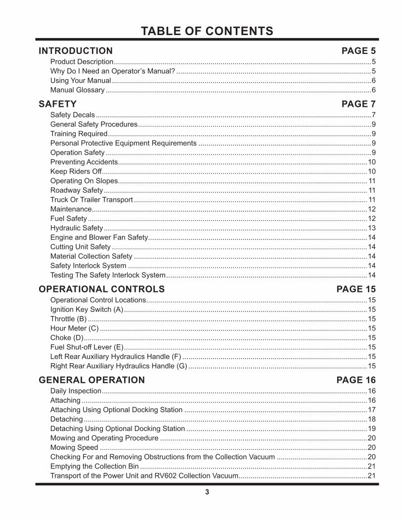
TABLE OF CONTENTS
3
INTRODUCTION PAGE 5Product Description ................................................................................................................................5Why Do I Need an Operator’s Manual? .................................................................................................5Using Your Manual .................................................................................................................................6Manual Glossary ....................................................................................................................................6
SAFETY PAGE 7Safety Decals .........................................................................................................................................7General Safety Procedures ....................................................................................................................9Training Required ...................................................................................................................................9Personal Protective Equipment Requirements ......................................................................................9Operation Safety ....................................................................................................................................9Preventing Accidents ............................................................................................................................10Keep Riders Off ....................................................................................................................................10Operating On Slopes ............................................................................................................................ 11Roadway Safety ................................................................................................................................... 11Truck Or Trailer Transport .................................................................................................................... 11Maintenance .........................................................................................................................................12Fuel Safety ...........................................................................................................................................12Hydraulic Safety ...................................................................................................................................13Engine and Blower Fan Safety .............................................................................................................14Cutting Unit Safety ...............................................................................................................................14Material Collection Safety ....................................................................................................................14Safety Interlock System .......................................................................................................................14Testing The Safety Interlock System ....................................................................................................14
OPERATIONAL CONTROLS PAGE 15Operational Control Locations ..............................................................................................................15Ignition Key Switch (A) .........................................................................................................................15Throttle (B) ...........................................................................................................................................15Hour Meter (C) .....................................................................................................................................15Choke (D) .............................................................................................................................................15Fuel Shut-off Lever (E) .........................................................................................................................15Left Rear Auxiliary Hydraulics Handle (F) ............................................................................................15Right Rear Auxiliary Hydraulics Handle (G) .........................................................................................15
GENERAL OPERATION PAGE 16Daily Inspection ....................................................................................................................................16Attaching ..............................................................................................................................................16Attaching Using Optional Docking Station ...........................................................................................17Detaching .............................................................................................................................................18Detaching Using Optional Docking Station ..........................................................................................19Mowing and Operating Procedure .......................................................................................................20Mowing Speed .....................................................................................................................................20Checking For and Removing Obstructions from the Collection Vacuum .............................................20Emptying the Collection Bin .................................................................................................................21Transport of the Power Unit and RV602 Collection Vacuum ................................................................21
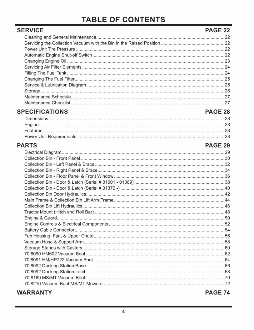
TABLE OF CONTENTS
4
SERVICE PAGE 22Cleaning and General Maintenance.....................................................................................................22Servicing the Collection Vacuum with the Bin in the Raised Position ..................................................22Power Unit Tire Pressure .....................................................................................................................22Automatic Engine Shut-off Switch ........................................................................................................22Changing Engine Oil ............................................................................................................................23Servicing Air Filter Elements ................................................................................................................24Filling The Fuel Tank ............................................................................................................................24Changing The Fuel Filter ......................................................................................................................25Service & Lubrication Diagram .............................................................................................................25Storage .................................................................................................................................................26Maintenance Schedule .........................................................................................................................27Maintenance Checklist .........................................................................................................................27
SPECIFICATIONS PAGE 28Dimensions ..........................................................................................................................................28Engine ..................................................................................................................................................28Features ...............................................................................................................................................28Power Unit Requirements ....................................................................................................................28
PARTS PAGE 29Electrical Diagram ................................................................................................................................29Collection Bin - Front Panel .................................................................................................................30Collection Bin - Left Panel & Brace ......................................................................................................32Collection Bin - Right Panel & Brace ....................................................................................................34Collection Bin - Floor Panel & Front Window .......................................................................................36Collection Bin - Door & Latch (Serial # 01001 - 01369) .......................................................................38Collection Bin - Door & Latch (Serial # 01370 -) ..................................................................................40Collection Bin Door Hydraulics .............................................................................................................42Main Frame & Collection Bin Lift Arm Frame .......................................................................................44Collection Bin Lift Hydraulics ................................................................................................................46Tractor Mount (Hitch and Roll Bar) ......................................................................................................48Engine & Guard ....................................................................................................................................50Engine Controls & Electrical Components ...........................................................................................52Battery Cable Connector ......................................................................................................................54Fan Housing, Fan, & Upper Chute .......................................................................................................56Vacuum Hose & Support Arm ..............................................................................................................58Storage Stands with Casters ................................................................................................................6070.8090 HM602 Vacuum Boot .............................................................................................................6270.8091 HM/HP722 Vacuum Boot .......................................................................................................6470.8092 Docking Station Base .............................................................................................................6670.8092 Docking Station Latch ............................................................................................................6870.8169 MS/MT Vacuum Boot .............................................................................................................7070.8210 Vacuum Boot MS/MT Mowers ................................................................................................72
WARRANTY PAGE 74
Introduction - 5
INTRODUCTION
Product Description
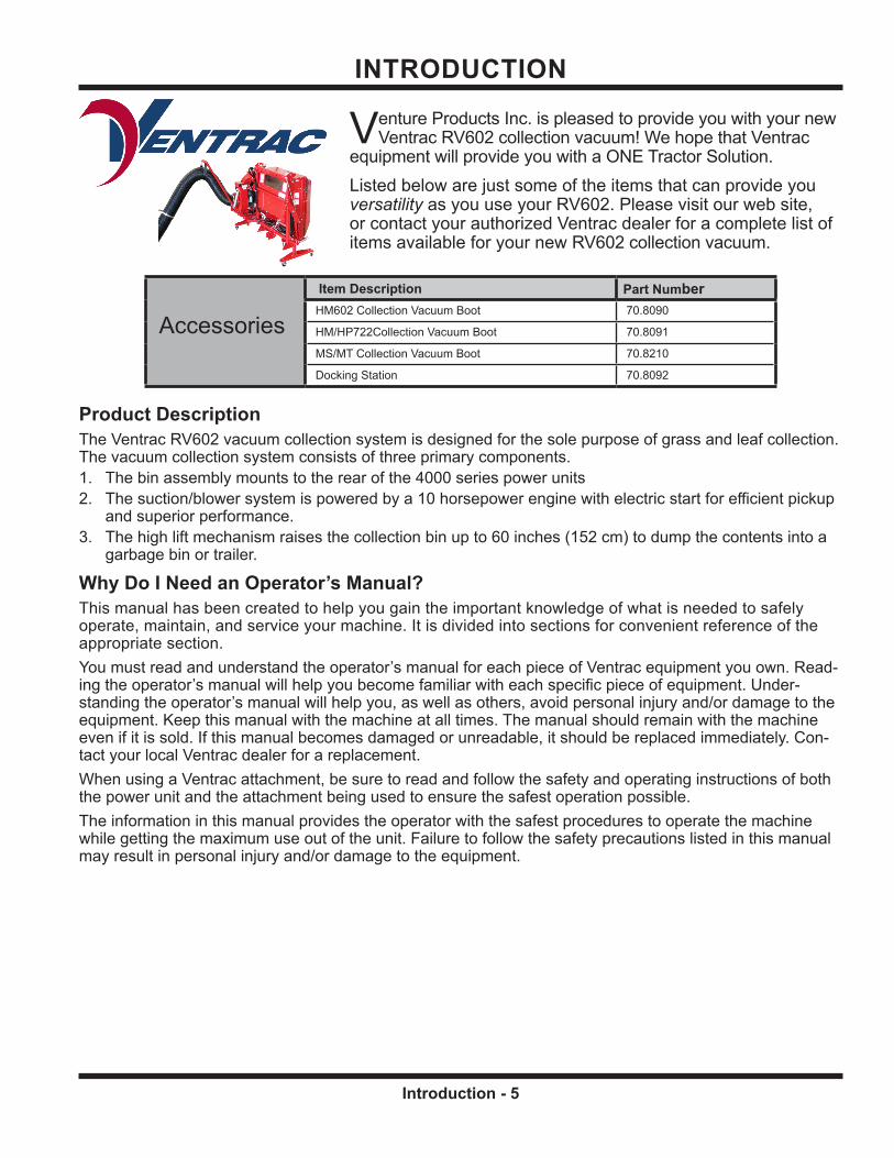
Accessories
Item Description Part NumberHM602 Collection Vacuum Boot 70.8090
HM/HP722Collection Vacuum Boot 70.8091
MS/MT Collection Vacuum Boot 70.8210
Docking Station 70.8092
The Ventrac RV602 vacuum collection system is designed for the sole purpose of grass and leaf collection. The vacuum collection system consists of three primary components.1. The bin assembly mounts to the rear of the 4000 series power units2. The suction/blower system is powered by a 10 horsepower engine with electric start for efficient pickup
and superior performance.3. The high lift mechanism raises the collection bin up to 60 inches (152 cm) to dump the contents into a
garbage bin or trailer.
Why Do I Need an Operator’s Manual?This manual has been created to help you gain the important knowledge of what is needed to safely operate, maintain, and service your machine. It is divided into sections for convenient reference of the appropriate section.You must read and understand the operator’s manual for each piece of Ventrac equipment you own. Read-ing the operator’s manual will help you become familiar with each specific piece of equipment. Under-standing the operator’s manual will help you, as well as others, avoid personal injury and/or damage to the equipment. Keep this manual with the machine at all times. The manual should remain with the machine even if it is sold. If this manual becomes damaged or unreadable, it should be replaced immediately. Con-tact your local Ventrac dealer for a replacement.When using a Ventrac attachment, be sure to read and follow the safety and operating instructions of both the power unit and the attachment being used to ensure the safest operation possible.The information in this manual provides the operator with the safest procedures to operate the machine while getting the maximum use out of the unit. Failure to follow the safety precautions listed in this manual may result in personal injury and/or damage to the equipment.
Venture Products Inc. is pleased to provide you with your new Ventrac RV602 collection vacuum! We hope that Ventrac
equipment will provide you with a ONE Tractor Solution.Listed below are just some of the items that can provide you versatility as you use your RV602. Please visit our web site, or contact your authorized Ventrac dealer for a complete list of items available for your new RV602 collection vacuum.

INTRODUCTION
Introduction - 6
Using Your ManualThroughout this manual, you will encounter special messages and symbols that identify potential safety concerns to help you as well as others avoid personal injury or damage to the equipment.
ATTENTIONThis symbol identifies potential health and safety hazards. It marks safety precautions. Your safety and the safety of others is involved.
SYMBOL DEFINITIONS
There are three signal words that describe the level of safety concern: Danger, Warning, and Caution. Safety should always be the #1 priority when working on or operating equipment. Accidents are more likely to occur when proper operating procedures are not followed or inexperienced operators are involved.Note: Right-Hand and Left-Hand orientations may be referred to at different places throughout this manual. Right-Hand and Left-Hand is determined as if sitting on the power unit seat facing forward.
SIGNAL WORD DEFINITIONS
Indicates a potentially hazardous situation which, if not avoided, could result in death or serious injury.
Indicates an imminently hazardous situation which, if not avoided, will result in death or serious injury. This signal word is limited to the most extreme cases.
Indicates a potentially hazardous situation which, if not avoided, may result in minor or moderate injury and/or property damage. It may also be used to alert against unsafe practices.
Manual GlossaryPower Unit A Ventrac tractor or other Ventrac engine powered device that may be operated by itself or
with an attachment or accessory.Attachment A piece of Ventrac equipment that requires a Power Unit for operation.Accessory A device that attaches to a Power Unit or Attachment to extend its capabilities.Machine Describes any “Attachment” or “Accessory” that is used in conjunction with a power unit.
Safety - 7
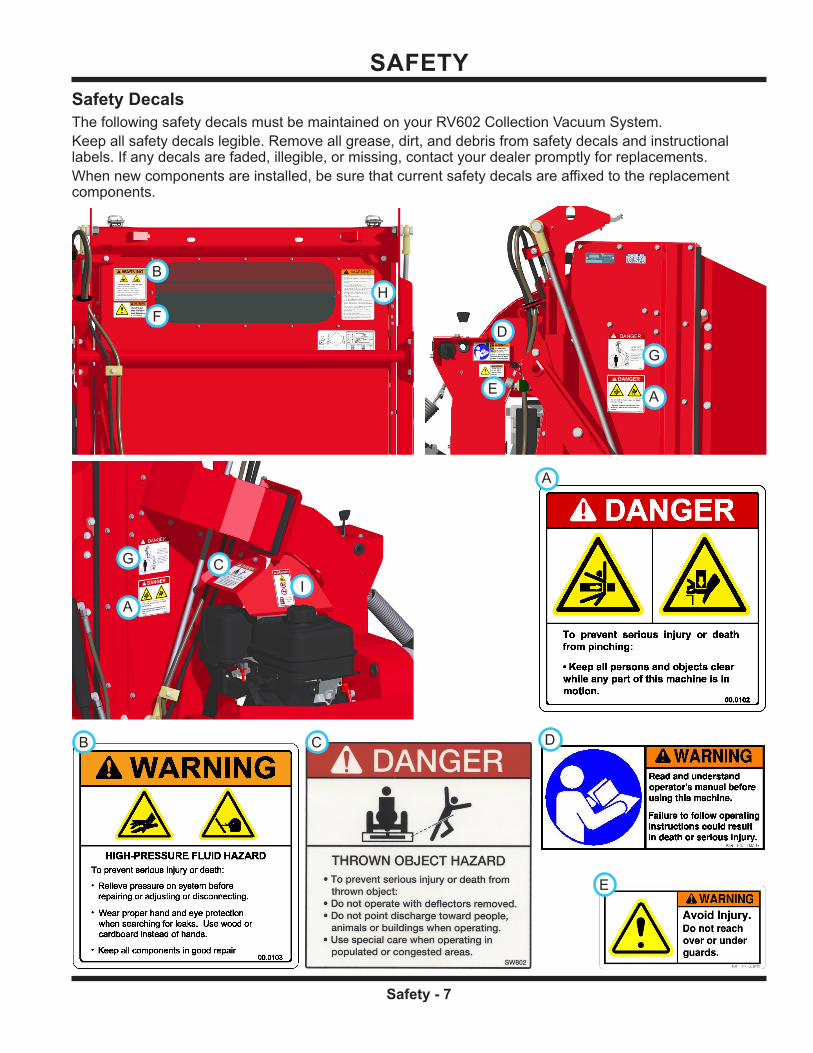
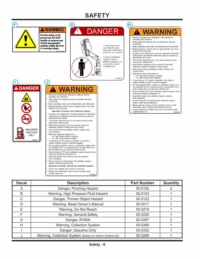
SAFETYSafety DecalsThe following safety decals must be maintained on your RV602 Collection Vacuum System.Keep all safety decals legible. Remove all grease, dirt, and debris from safety decals and instructional labels. If any decals are faded, illegible, or missing, contact your dealer promptly for replacements.When new components are installed, be sure that current safety decals are affixed to the replacement components.
A
D
E
GG
B
FFH
A
CGG
II
A
B C D
E
SAFETY
Safety - 8
Decal Description Part Number QuantityA Danger, Pinching Hazard 00.0102 2B Warning, High Pressure Fluid Hazard 00.0103 1C Danger, Thrown Object Hazard 00.0122 1D Warning, Read Owner’s Manual 00.0217 1E Warning, Do Not Reach 00.0219 1F Warning, General Safety 00.0220 1G Danger, RV600 00.0267 2H Warning, Collection System 00.0269 1I Danger, Gasoline Only 00.0332 1J Warning, Collection System (Decal on tractor toolbox lid) 00.0268 1
FF GG
II
H
JJ

SAFETY
Safety - 9
General Safety Proceduresfor Ventrac Power Units, Attachments, & Accessories
Training Required• The owner of this machine is solely responsible for properly training the operators.• The owner/operator is solely responsible for the operation of this
machine and prevention of accidents or injuries occurring to him/her-self, other people, or property.
• Do not allow operation or service by children or untrained personnel. Local regulations may restrict the age of the operator.
• Before operating this machine, read the operator’s manual and under-stand its contents.
• If the operator of the machine cannot understand this manual, then it is the responsibility of this machine’s owner to fully explain the material within this manual to the operator.
• Learn and understand the use of all controls.• Know how to stop the power unit and all attachments quickly in the event of an emergency.
Personal Protective Equipment RequirementsIt is the responsibility of the owner to be sure that the operators use the proper personal protective equip-ment while operating the machine. Required personal protective equipment includes, but is not limited to, the following list.
• Wear a certified ear protection device to prevent loss of hearing.• Prevent eye injury by wearing safety glasses while operating the machine.• Closed toe shoes must be worn at all times.• Long pants must be worn at all times.• When operating in dusty conditions, it is recommended that a dust mask be worn.
Operation Safety• Inspect machine before operation. Repair or replace any damaged, worn, or missing parts. Be sure
guards and shields are in proper working condition and are secured in place. Make all necessary adjustments before operating machine.
• Some pictures in this manual may show shields or covers opened or removed in order to clearly illustrate any instructions. Under no circumstance should the machine be operated without these devices in place.
• Alterations or modifications to this machine can reduce safety and could cause damage to the machine. Do not alter safety devices or operate with shields or covers removed.
• Before each use, verify that all controls function properly and inspect all safety devices. Do not operate if controls or safety devices are not in proper working condition.
• Check parking brake function before operating. Repair or adjust parking brake if necessary.• Observe and follow all safety decals.• All controls are to be operated from the operator’s station only.• Always wear a seat belt if the machine has a roll cage/bar installed and in upright position.• Ensure the attachment or accessory is locked or fastened securely to the power unit before operating.• Ensure that all bystanders are clear of the power unit and attachment before operating. Stop machine if
someone enters your work area.• Always be alert to what is happening around you, but do not lose focus on the task you are performing.
Always look in the direction the machine is moving.• Look behind and down before backing up to be sure of a clear path.• If you hit an object, stop and inspect the machine. Make all necessary repairs before operating machine again.• Stop operation immediately at any sign of equipment failure. An unusual noise can be a warning of equipment
failure or a sign that maintenance is required. Make all necessary repairs before operating machine again.

SAFETY
Safety - 10
General Safety Proceduresfor Ventrac Power Units, Attachments, & Accessories
• If equipped with a high/low range feature, never shift between high and low range while on a slope. Always move the machine to level ground and engage the parking brake before shifting range.
• Do not leave machine unattended while it is running.• Always park the machine on level ground.• Always shut off engine when connecting attachment drive belt to the power unit.• Never leave the operator’s station without lowering the attachment to the ground, setting the parking
brake, shutting off the engine, and removing the ignition key. Make sure all moving parts have come to a complete stop before dismounting.
• Never leave equipment unattended without lowering the attachment to the ground, setting the parking brake, shutting off the engine, and removing the ignition key.
• Only operate in well-lit conditions.• Do not operate when there is a risk of lightning.• Never direct the discharge of any attachment in the direction of people, buildings, animals, vehicles, or
other objects of value.• Never discharge material against a wall or obstruction. Material may ricochet back towards the operator.• Use extra caution when approaching blind corners, shrubs, trees, or other objects that may obscure vision.• Do not run the engine in a building without adequate ventilation.• Do not touch the engine or the muffler while the engine is running or immediately after stopping the engine.
These areas may be hot enough to cause a burn.• Do not change the engine governor settings or over-speed the engine. Operating engine at excessive speed
may increase the hazard of personal injury.• To reduce the hazard of fire, keep the battery compartment, engine, and muffler areas free of grass, leaves,
excessive grease, and other flammable materials.
Preventing Accidents
• Clear working area of objects that might be hit or thrown from machine.• Keep people and pets out of working area.• Know the work area well before operation. Do not operate where traction or
stability is questionable.• Reduce speed when you are operating over rough ground.• Equipment can cause serious injury and/or death when improperly used.
Before operating, know and understand the operation and safety of the power unit and the attachment being used.
• Do not operate machine if you are not in good physical and mental health, if you will be distracted by personal devices, or are under the influence of any substance which might impair deci-sion, dexterity, or judgment.
• Children are attracted to machine activity. Be aware of children and do not allow them in the working area. Turn off the machine if a child enters the work area.
Keep Riders Off• Only allow the operator on the power unit. Keep riders off.• Never allow riders on any attachment or accessory.
Operation Safety (continued)

SAFETY
Safety - 11
General Safety Proceduresfor Ventrac Power Units, Attachments, & Accessories
Operating On Slopes• Slopes can cause loss-of-control and
tip-over accidents, which can result in severe injury or death. Be familiar with the emergency parking brake, along with the power unit controls and their functions.
• If power unit is equipped with a fold down roll bar, it must be locked in the upright position when operating on any slope.
• Use low range (if equipped) when operating on slopes greater than 15 degrees.
• Do not stop or start suddenly when operating on slopes.• Never shift between high and low range while on a slope. Always move the power unit to level ground
and engage the parking brake before shifting range or placing the power unit in neutral.• Variables such as wet surface and loose ground will reduce the degree of safety. Do not drive where
machine could lose traction or tip over.• Keep alert for hidden hazards in the terrain.• Stay away from drop-offs, ditches, and embankments.• Sharp turns should be avoided when operating on slopes.• Pulling loads on hills decreases safety. It is the responsibility of the owner/operator to determine loads
that can safely be controlled on slopes.• Transport machine with attachment lowered or close to the ground to improve stability.• While operating on slopes, drive in an up and down direction when possible. If turning is necessary
while driving across slopes, reduce speed and turn slowly in the downhill direction.• Assure a sufficient supply of fuel for continuous operation. A minimum of one-half tank of fuel is recommended.
Roadway Safety• Operate with safety lights when operating on or near roadways.• Obey all state and local laws concerning operation on roadways.• Slow down and be careful of traffic when operating near or crossing roadways. Stop before crossing
roads or sidewalks. Use care when approaching areas or objects that may obscure vision.• If there is doubt of safety conditions, discontinue machine operation until a time when
operation can be performed safely.• When operating near or on roadways, have a Slow Moving Vehicle Emblem clearly
displayed.
Truck Or Trailer Transport• Use care when loading or unloading machine into a truck or trailer.• Use full width ramps for loading machine into a truck or trailer.• The parking brake is not sufficient to lock the machine during transport. Always secure the power unit
and/or attachment to the transporting vehicle securely using straps, chains, cable, or ropes. Both front and rear straps should be directed down and outward from the machine.
• Shut off fuel supply to power unit during transport on truck or trailer.• If equipped, turn the battery disconnect switch to the Off position to shut off electrical power.

SAFETY
Safety - 12
General Safety Proceduresfor Ventrac Power Units, Attachments, & Accessories
Maintenance• Keep all safety decals legible. Remove all grease dirt, and debris from safety decals and instructional labels.• If any decals are faded, illegible, or missing, contact your dealer promptly for replacements.• When new components are installed, be sure that current safety decals are affixed to the replacement
components.• If any component requires replacement, use only original Ventrac replacement parts.• Always turn the battery disconnect to the Off position or disconnect the battery before performing any
repairs. Disconnect the negative terminal first and the positive terminal last. Reconnect the positive terminal first and the negative terminal last.
• Keep all bolts, nuts, screws, and other fasteners properly tightened.• Always lower the attachment to the ground, engage parking brake, shut off engine, and remove the
ignition key. Make sure all moving parts have come to a complete stop before cleaning, inspection, adjusting or repairing.
• If the power unit, attachment, or accessory requires repairs or adjustments not instructed in the operator’s manual, the power unit, attachment, or accessory must be taken to an authorized Ventrac dealer for service.
• Never perform maintenance on the power unit and/or attachment if someone is in the operator’s station.• Always use protective glasses when handling the battery.• Check all fuel lines for tightness and wear on a regular basis. Tighten or repair them as needed.• To reduce the hazard of fire, keep the battery compartment, engine, and muffler areas free of grass,
leaves, and excessive grease.• Do not touch the engine, the muffler, or other exhaust components while the engine is running or imme-
diately after stopping the engine. These areas may be hot enough to cause a burn.• Allow the engine to cool before storing and do not store near an open flame.• Do not change the engine governor settings or over-speed the engine. Operating engine at excessive
speed may increase the hazard of personal injury.• Springs may contain stored energy. Use caution when disengaging or removing springs and/or spring
loaded components.• An obstruction or blockage in a drive system or moving/rotating parts may cause a buildup of stored
energy. When the obstruction or blockage is removed, the drive system or moving/rotating parts may move suddenly. Do not attempt to remove an obstruction or blockage with your hands. Keep hands, feet, and clothing away from all power-driven parts.
• Dispose of all fluids in accordance with local laws.
Fuel Safety• To avoid personal injury or property damage, use extreme care in handling gasoline. Gaso-
line is extremely flammable and the vapors are explosive.• Do not refuel machine while smoking or at a location near flames or sparks.• Always refuel the machine outdoors.• Do not store machine or fuel container indoors where fumes or fuel can reach an open
flame, spark, or pilot light.• Only store fuel in an approved container. Keep out of reach of children.• Never fill containers inside a vehicle or on a truck or trailer bed with a plastic liner. Always place containers
on the ground away from your vehicle before filling.• Remove machine from the truck or trailer and refuel it on the ground. If this is not possible, refuel the
machine using a portable container, rather than from a fuel dispenser nozzle.• Never remove fuel cap or add fuel with the engine running. Allow engine to cool before refueling.• Never remove fuel cap while on a slope. Only remove when parked on a level surface.• Replace all fuel tank and container caps securely.

SAFETY
Safety - 13
General Safety Proceduresfor Ventrac Power Units, Attachments, & Accessories
• Do not overfill fuel tank. Only fill to bottom of fuel neck, do not fill fuel neck full. Overfilling of fuel tank could result in engine flooding, fuel leakage from the tank, and/or damage to the emissions control system.
• If fuel is spilled, do not attempt to start the engine. Move the power unit away from the fuel spill and avoid creating any source of ignition until fuel vapors have dissipated.
• If the fuel tank must be drained, it should be drained outdoors into an approved container.• Dispose of all fluids in accordance with local laws.• Check all fuel lines for tightness and wear on a regular basis. Tighten or repair them as needed.• The fuel system is equipped with a shut-off valve. Shut off the fuel when transporting the machine to
and from the job, when parking the machine indoors, or when servicing the fuel system.
Hydraulic Safety• Make sure all hydraulic connections are tight and all hydraulic hoses and tubes are in good condition.
Repair any leaks and replace any damaged or deteriorated hoses or tubes before starting the machine.• Hydraulic leaks can occur under high pressure. Hydraulic leaks require special care and attention.• Use a piece of cardboard and a magnifying glass to locate sus-
pected hydraulic leaks.• Keep body and hands away from pinhole leaks
or nozzles that eject high pressure hydraulic fluid. Hydraulic fluid escaping under high pressure can penetrate the skin causing serious injury, leading to severe complications and/or secondary infections if left untreated. If hydraulic fluid is injected into the skin, seek immediate medical attention no matter how minor the injury appears.
• Hydraulic system may contain stored energy. Before performing maintenance or repairs on the hydraulic system, remove attachments, engage parking brake, disengage weight transfer system (if equipped), shut off engine, and remove ignition key. To relieve pressure on the auxiliary hydraulic system, shut off the power unit engine and move the hydraulic control lever left and right before disconnecting the auxiliary hydraulic quick couplers.
• Dispose of all fluids in accordance with local laws.
Fuel Safety (continued)

SAFETY
Safety - 14
RV602 Safety Procedures
• Maximum degree of operation is 10° if the power unit is equipped with single wheels or 15° if the power unit is equipped with dual wheels. On slopes of 10° or greater, the power unit’s weight transfer system must be engaged.
• Do not operate power unit, mower, or collection vacuum with the collection bin in a raised position except when on a level surface and to empty the collection bin.
• A mower deck must be attached to the front of the power unit anytime the collection system is attached.• The mower deck must be in the raised position when raising the collection bin.• Shut off both the power unit and the collection vacuum engines when refueling.• Do not connect or disconnect the collection vacuum battery cable while refueling.
Engine and Blower Fan Safety• Rotating fan blades may cause personal injury. Never operate the RV602 collection vacuum with the
hose removed, the inlet duct removed, or the collection bin in the raised position. Always remove the ignition key and ensure that all moving parts have stopped rotating before servicing.
Cutting Unit Safety• Rotating Blades: Contact with the rotating mower blades or other moving parts may cause
personal injury. Keep hands and feet away.• Rotation of one blade may cause another blade to rotate.• DO NOT modify or remove any of this equipment’s shields, safety devices, or warning labels.• Never operate the mower deck without the discharge chute or the collection boot in place.• Thrown Object Hazard: Do not point discharge toward people, animals, or buildings when operating.
Never operate with the deflectors removed.• When not mowing, always shut off the PTO to stop the mower blades.
Material Collection Safety• Always empty the collection vacuum after every use. Do not store with material left in the collection bin.
Decomposing material stored in the collection bin may result in spontaneous combustion.
Safety Interlock SystemIf the collection bin is raised while the collection vacuum engine is running, the engine will automatically shut off. The engine can be restarted after the collection bin is lowered and it is safe to resume operation.
Testing The Safety Interlock SystemPerform the following safety interlock tests daily. Test the switch operation according to the following procedure.• Confirm the collection bin is lowered completely to the down position.• Start the collection vacuum engine.• Raise the collection bin. The collection vacuum engine should automatically shut off within the first two
inches (5 cm) of movement of the collection bin.If this test fails, do not use the RV602. Refer to Automatic Engine Shut-off Switch in the service section of this manual for servicing procedures.
WARNINGThe engine exhaust from this product contains chemicals known to the State of California to cause cancer, birth defects, or other reproductive harm.
CALIFORNIA PROPOSITION 65Battery Warning
Battery posts, terminals, and related accessories contain lead and lead compounds, chemicals known to the State of California to cause cancer and reproductive harm. Wash hands after handling!

Operation - 15
OPERATIONAL CONTROLS
AA
BB
CC
DD
EE
GGFF
Operational Control LocationsThe images above match with the following refer-ence letters to help identify the location of opera-tional controls for the RV602 collection vacuum.A - Ignition Key SwitchB - ThrottleC - Hour MeterD - ChokeE - Fuel Shut-off LeverF - Left Rear Auxiliary Hydraulics HandleG - Right Rear Auxiliary Hydraulics Handle
Ignition Key Switch (A)1. Off or Stop Position.
Shuts off the collection vacuum engine.
2. On or Run Position. Engine run position.
3. Start Position. When key is turned to the start position, the starter will engage.
Throttle (B)Moving the lever to the right increases the engine Revolutions Per Minute (RPM). Moving the lever to the left slows the engine to an idle.
Hour Meter (C)Displays the engine run time in hours.
Choke (D)Moving the choke lever to the choke position aids in starting a cold engine.
Fuel Shut-off Lever (E)The fuel shut-off lever controls the flow of fuel to the collection vacuum engine. Moving the fuel shut-off lever to the left shuts off the flow of fuel to the engine. Turn off the fuel shut-off valve when trans-porting the collection vacuum on a truck or trailer and when parking the collection vacuum indoors.
Left Rear Auxiliary Hydraulics Handle (F)The collection bin is raised and lowered using the left rear auxiliary hydraulics handle. Pull back on this handle to raise the collection bin. Push forward on this handle to lower the collection bin.
Right Rear Auxiliary Hydraulics Handle (G)The collection bin door is opened and closed using the right rear auxiliary hydraulics handle. Pull back on the lever to open the door. Push forward on the lever to close and latch the door.
*
*
* Refer to power unit operator’s manual for operation of power unit controls.
11
33
22
Operation - 16
GENERAL OPERATIONDaily Inspection
1.
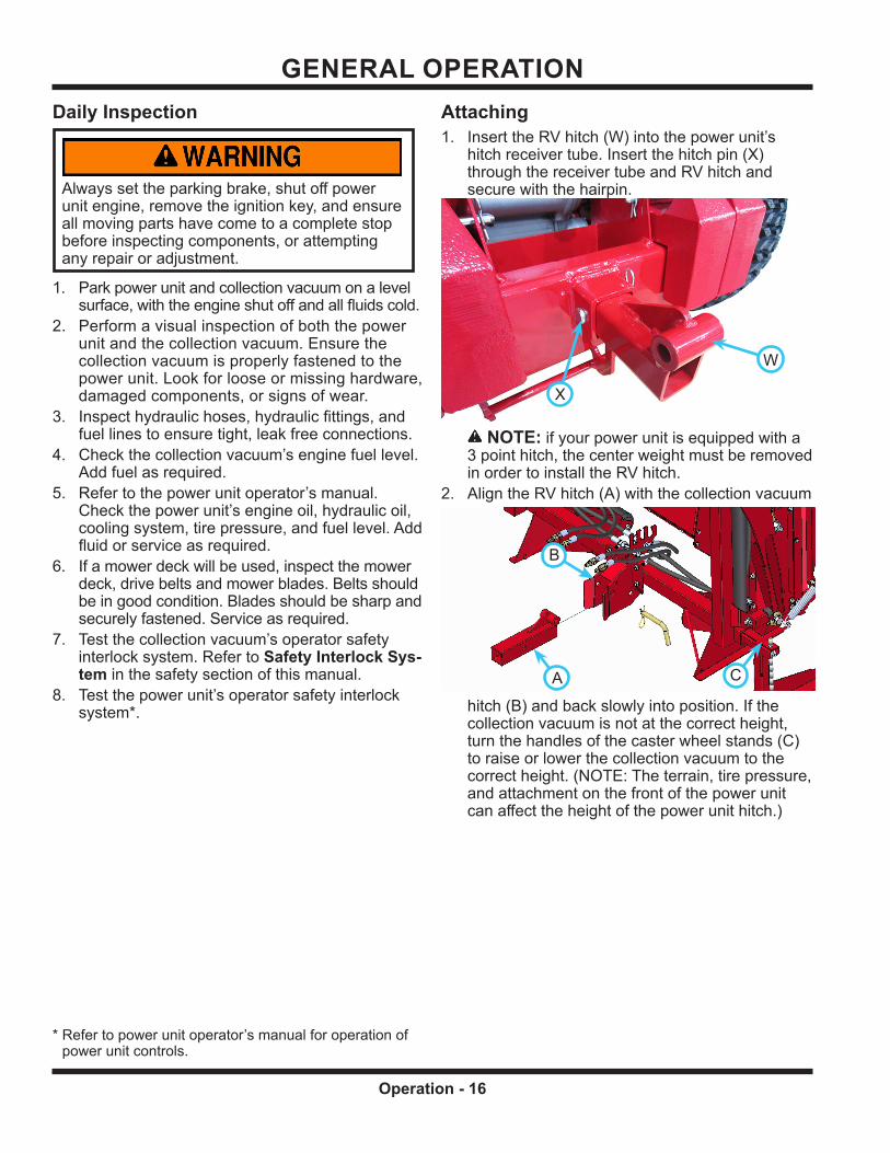
Always set the parking brake, shut off power unit engine, remove the ignition key, and ensure all moving parts have come to a complete stop before inspecting components, or attempting any repair or adjustment.
Park power unit and collection vacuum on a level surface, with the engine shut off and all fluids cold.
2. Perform a visual inspection of both the power unit and the collection vacuum. Ensure the collection vacuum is properly fastened to the power unit. Look for loose or missing hardware, damaged components, or signs of wear.
3. Inspect hydraulic hoses, hydraulic fittings, and fuel lines to ensure tight, leak free connections.
4. Check the collection vacuum’s engine fuel level. Add fuel as required.
5. Refer to the power unit operator’s manual. Check the power unit’s engine oil, hydraulic oil, cooling system, tire pressure, and fuel level. Add fluid or service as required.
6. If a mower deck will be used, inspect the mower deck, drive belts and mower blades. Belts should be in good condition. Blades should be sharp and securely fastened. Service as required.
7. Test the collection vacuum’s operator safety interlock system. Refer to Safety Interlock Sys-tem in the safety section of this manual.
8. Test the power unit’s operator safety interlock system*.
Attaching1. Insert the RV hitch (W) into the power unit’s
hitch receiver tube. Insert the hitch pin (X) through the receiver tube and RV hitch and secure with the hairpin.
WW
XX
NOTE: if your power unit is equipped with a 3 point hitch, the center weight must be removed in order to install the RV hitch.
2. Align the RV hitch (A) with the collection vacuum
hitch (B) and back slowly into position.
AA
BB
CC
If the collection vacuum is not at the correct height, turn the handles of the caster wheel stands (C) to raise or lower the collection vacuum to the correct height. (NOTE: The terrain, tire pressure, and attachment on the front of the power unit can affect the height of the power unit hitch.)
* Refer to power unit operator’s manual for operation of power unit controls.

GENERAL OPERATION
Operation - 17
3. Install the pin (D) to couple the power unit hitch to the collection vacuum hitch. On power units equipped with standard hitch, install pin in location Y. On power units equipped with 3 point hitch, install pin in location Z.
4.
ZZ
YY
DD
Engage the roll bar latches (E) to the roll bar mounts (F) and install the retainer pins (G).
5.
EE
FF GG
Connect the left set of hydraulic hoses to the left hydraulic couplers of the power unit. Match the red and yellow indicators on the hose ends to the corresponding indicators on the quick couplers.
6. Connect the right set of hydraulic hoses to the right hydraulic couplers of the power unit. Match the red and yellow indicators on the hose ends to the cor-responding indicators on the quick couplers.
7. Connect the battery cable to the quick connect plug located to the left of the hydraulic couplers.
8. Remove the caster wheel stands.9. Connect the mower collection boot to the mower
deck. (May require the removal of the flexible discharge chute.) Install the keeper pins (H) to secure the collection boot to the mower deck.
10.
HH
HH
Connect the suction hose (I) to the collection boot (J). Fasten the clamp (K) in place to secure the suction hose to the collection boot.
IIJJ
KK

GENERAL OPERATION
Operation - 18
Attaching Using Optional Docking Station1. Insert the RV hitch (W) into the power unit’s
hitch receiver tube. Insert the hitch pin (X) through the receiver tube and RV hitch and secure with the hairpin.
WW
XX
WW
XX
NOTE: if your power unit is equipped with a 3 point hitch, the center weight must be removed in order to install the RV hitch.
2. Align the RV hitch (A) with the collection vacuum hitch (B) and back slowly into position.
3.
AA
BB
Install the pin (C) to couple the power unit hitch to the collection vacuum hitch. On power units equipped with standard hitch, install pin in location Y. On power units equipped with 3 point hitch, install pin in location Z.
ZZ
YY
DD
4. Engage the roll bar latches (E) to the roll bar mounts (F) and install the retainer pins (G).
5.
EE
FF GG
Connect the left set of hydraulic hoses to the left hydraulic couplers of the power unit. Match the red and yellow indicators on the hose ends to the corresponding indicators on the quick couplers.
6. Connect the right set of hydraulic hoses to the right hydraulic couplers of the power unit. Match the red and yellow indicators on the hose ends to the cor-responding indicators on the quick couplers.
7. Connect the battery cable to the quick connect plug located to the left of the hydraulic couplers.

GENERAL OPERATION
Operation - 19
8. Rotate the docking station handle (G) to release the collection vacuum from the docking station.
9.
GG LatchedLatched
ReleasedReleased
Connect the mower collection boot to the mower deck. (May require the removal of the flexible discharge chute.) Install the keeper pins (H) to secure the collection boot to the mower deck.
10.
HH
HH
Connect the suction hose (I) to the collection boot (J). Fasten the clamp (K) in place to secure the suction hose to the collection boot.
IIJJ
KK
Detaching1. Ensure the collection bin is empty, the collection
bin door is closed and latched, and the collection bin is lowered completely to the down position.
2.
Always empty the collection bin after use. Never store the collection vacuum with material in the collection bin.
Position the power unit so the collection vacuum is at the desired location for detachment.
3. Place the power unit in park and shut off the engine. Move the lift and door hydraulic levers to relieve pressure that may be present in the hydraulic system.
4. Install the caster wheel stands (one on each side of the collection vacuum). Turn the handles until some of the weight is on the caster wheel stands and the collection vacuum begins to rise.
5. Disconnect the collection boot from the mower deck (if attached).
6. Disconnect the four hydraulic hoses and store them in the hose holder.
7. Disconnect the battery cable.
8. Remove the retainer pins from the roll bar latches, release the latches, and unhook the latches from the roll bar mounts.
Resume raising the collection vacuum with the caster wheel stands. Lift the collection vacuum until the weight is no longer on the power unit. When the hitch pin turns freely, remove the secur-ing clip and remove the pin. The power unit can now be driven away from the collection vacuum.
Never operate the mower deck without the dis-charge chute or the collection boot in place.
GENERAL OPERATION
Operation - 20
Detaching Using Optional Docking Station1. Ensure the collection bin is empty, the collection
bin door is closed and latched, and the collection bin is lowered completely to the down position.
2.
Always empty the collection bin after use. Never store the collection vacuum with material in the collection bin.
Ensure the docking station is in the released position. Back the collection vacuum onto the docking station until it contacts the stops.
3. Place the power unit in park and shut off the engine. Move the lift and door hydraulic levers to relieve pressure that may be present in the hydraulic system.
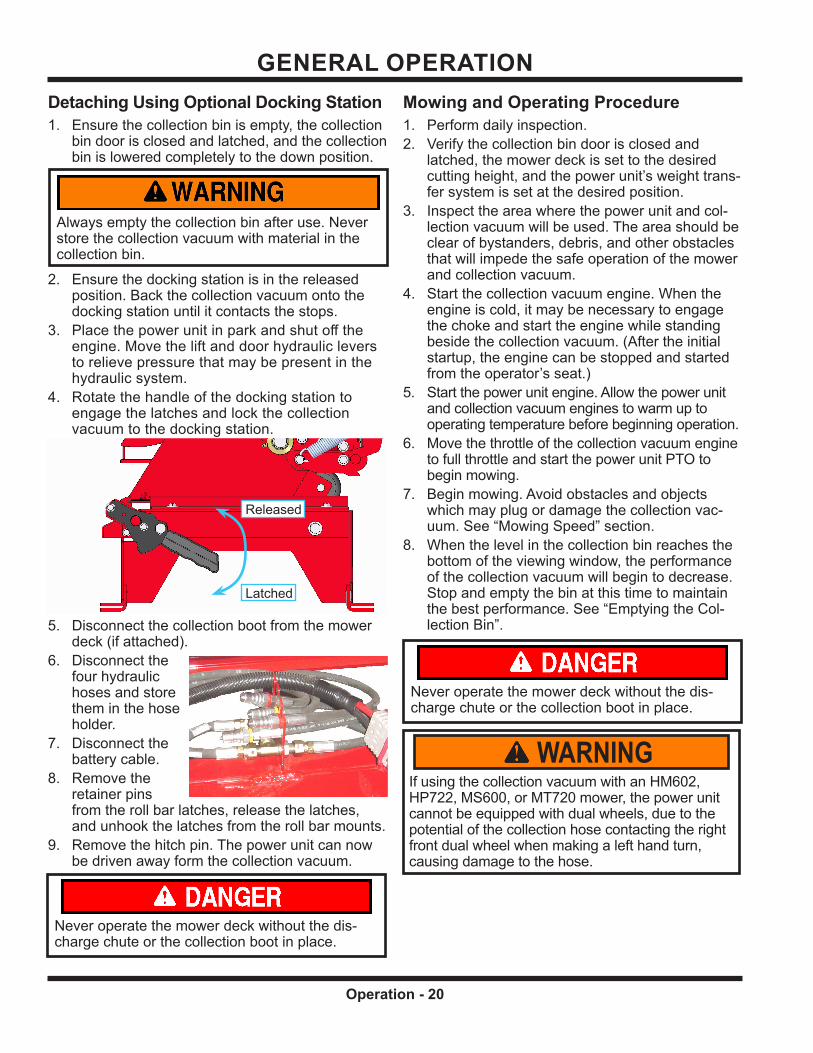
4. Rotate the handle of the docking station to engage the latches and lock the collection vacuum to the docking station.
5.
LatchedLatched
ReleasedReleased
Disconnect the collection boot from the mower deck (if attached).
6. Disconnect the four hydraulic hoses and store them in the hose holder.
7. Disconnect the battery cable.
8. Remove the retainer pins from the roll bar latches, release the latches, and unhook the latches from the roll bar mounts.
9. Remove the hitch pin. The power unit can now be driven away form the collection vacuum.
Never operate the mower deck without the dis-charge chute or the collection boot in place.
Mowing and Operating Procedure1. Perform daily inspection.2. Verify the collection bin door is closed and
latched, the mower deck is set to the desired cutting height, and the power unit’s weight trans-fer system is set at the desired position.
3. Inspect the area where the power unit and col-lection vacuum will be used. The area should be clear of bystanders, debris, and other obstacles that will impede the safe operation of the mower and collection vacuum.
4. Start the collection vacuum engine. When the engine is cold, it may be necessary to engage the choke and start the engine while standing beside the collection vacuum. (After the initial startup, the engine can be stopped and started from the operator’s seat.)
5. Start the power unit engine. Allow the power unit and collection vacuum engines to warm up to operating temperature before beginning operation.
6. Move the throttle of the collection vacuum engine to full throttle and start the power unit PTO to begin mowing.
7. Begin mowing. Avoid obstacles and objects which may plug or damage the collection vac-uum. See “Mowing Speed” section.
8. When the level in the collection bin reaches the bottom of the viewing window, the performance of the collection vacuum will begin to decrease. Stop and empty the bin at this time to maintain the best performance. See “Emptying the Col-lection Bin”.
WARNINGIf using the collection vacuum with an HM602, HP722, MS600, or MT720 mower, the power unit cannot be equipped with dual wheels, due to the potential of the collection hose contacting the right front dual wheel when making a left hand turn, causing damage to the hose.
Never operate the mower deck without the dis-charge chute or the collection boot in place.

GENERAL OPERATION
Operation - 21
Mowing SpeedWhen using the collection vacuum, travel speed will typically need to be slower than when mowing without the collection vacuum.Travel speed may need to be further reduced when mowing thick, tall, or wet grass or leaves.Travel speed may be increased in normal mowing situations or as conditions safely allow.If clippings are not being picked up, the travel speed may need reduced, or there may be an obstruction present in the collection vacuum. See “Checking For and Removing Obstructions from the Collection vacuum”.
Checking For and Removing Obstruc-tions from the Collection VacuumIn thick, tall, or wet grass, the potential increases for an obstruction to develop and plug the collection vacuum. Additionally, if the collection bin is over-filled, an obstruction may develop.1. If an obstruction develops, stop the power unit,
set the parking brake, shut off the power unit PTO, and shut off the collection vacuum engine. Wait until all parts have stopped moving before leaving the operator’s seat.
2. Check the collection boot first. Uncouple the suction hose from the collection boot. If an obstruction is present, remove the obstruction from the collection boot.
3. Check the suction hose. With the hose uncou-pled from the collection boot, shake the suction hose so that any material present in the suction hose will fall out. Pull material out, if necessary.
4. If the obstruction is not in either the collection boot or the suction hose, the obstruction may be present in the outlet of the fan system. Raise the collection bin and install the cylinder lock-out to secure the bin in the raised position. Remove any material using a stick or similar object.
5. In rare occasions, the inlet to the fan can become obstructed. If this occurs, remove the suction hose from the fan inlet and remove the obstruction.
Emptying the Collection Bin1. When it is time to empty the collection bin, shut
off the power unit PTO and slow the collection vacuum engine to an idle. Drive the power unit and collection vacuum to the location that the col-lection bin will be emptied. Turn off the collection vacuum engine when the location is reached.
2. With the power unit on level ground, back the power unit to approximately six feet away from the receptacle or disposal area.
3.
AttentionWhen raising the collection bin, the mower deck must also be in the raised position.
Raise the collection bin to the required height for the receptacle. If emptying on the ground, the bin does not need raised to open the collection bin door.
4. Back the power unit up until the collection bin is over the receptacle or disposal area.
5. Open the collection bin door to empty the collec-tion bin.
6. After the collection bin is empty, close the collec-tion bin door.
7. Drive the power unit forward until the bin can be lowered without contact with the receptacle.
8. Lower the collection bin.9. The collection vacuum is now ready to resume
mowing. NOTE: Periodically check the air intake of the collec-tion vacuum engine to ensure that material does not accumulate on the air intake. Check more frequently if emptying the collection bin during windy conditions.
Transport of the Power Unit and RV602 Collection VacuumAlways shut off the collection vacuum engine and the power unit PTO prior to transport.Always empty the collection bin prior to transport.Always lower the collection bin to the operating posi-tion and raise the mower deck prior to transport.Always drive carefully, exercising caution on slopes and when making turns.

Service - 22
SERVICE
Cleaning and General MaintenanceFor best results, and to maintain the finish of the RV602 collection vacuum, clean or wash the equip-ment to remove accumulated clippings, leaves, or dirt when the job is finished.When washing, always allow time for the equip-ment to cool before cleaning, Exercise caution to avoid spraying water directly into bearings, seals, or the engine. After washing, it is important to run the mower and the collection vacuum engine to dis-perse accumulated water.
Servicing the Collection Vacuum with the Bin in the Raised Position
A cylinder lockout is provided with the RV602 and is stored on the right lift arm of the collection vacuum. To use, raise the collection bin to the highest posi-tion. Remove the cylinder lockout from the storage position and install over the rod of the right lift cylin-
der. Use the safety snap pin to secure the cylinder lockout to the cylinder.
Power Unit Tire PressureSingle tires - Inflate all tires to 15 psi (103 kPa).Dual wheels - Inflate inner tires to 15 psi (103 kPa) and outer tires to 6-8 psi (41-55 kPa).
Automatic Engine Shut-off SwitchWhen the collection vacuum bin is raised, the col-lection vacuum engine should automatically shut off within the first 2 inches (5 cm) of bin travel. If the engine fails to shut off within the first 2 inches (5 cm) of movement, the shut-off switch must be adjusted. Alternately, if the switch is out of adjustment, it may prevent the collection vacuum engine from starting even when the bin is completely lowered.If the switch needs to be adjusted in or out, loosen the nuts (A) that secure the switch and adjust the switch location so that the engine shut-off occurs when directed. If the switch needs to be adjusted side to side, loosen the bolts (B) that fasten the switch bracket to the fan housing and adjust the switch so that it is centered with the right bin lift arm.
AA
BB
After switch is properly positioned, retighten the nuts and/or bolts. Contact your Ventrac servicing dealer if, after adjusting the switch, the engine still does not shut off within the first 2 inches (5 cm) of travel.
Always set the parking brake, shut off power unit engine, remove the ignition key, and ensure all moving parts have come to a complete stop before inspecting components or attempting any repair or adjustment.
AttentionIf any component requires replacement, use only original Ventrac replacement parts.

SERVICE
Service - 23
Checking Engine Oil Level
1.
ATTENTION: Avoid damage to your engine. Failure to check the oil level regularly could lead to serious damage to your engine if the engine is run with an incorrect oil level. • Before operation, check engine oil with the unit
sitting on a level surface.• Check oil level when the engine is cold and not
running• Keep oil level between the FULL and ADD marks. • Shut off engine before adding oil.
Park the power unit and collection vacuum on a level surface.
2. Engage the power unit’s parking brake and shut off the engine.
3. Remove the power unit’s key from the ignition switch.
4. Shut off the collection vacuum engine and remove the ignition key from the switch.
5. Allow the engine and oil to cool.6. Remove the dipstick (A) located at the base of
the engine, behind the fan housing.
7.
AA
BB
CC
Check oil level. The oil level should be between the Full (B) and Add (C) marks of the dipstick.
8. If the oil level is low, add small amounts of oil to bring the oil level no higher than the full mark of the dipstick.
9. If the oil level is above the full mark, drain to achieve the proper oil level.
Changing Engine Oil
1.
CAUTIONContact with engine oil can irritate your skin. Wear protective gloves when working with engine oil. If you come in contact with engine oil, wash it off immediately.
CAUTIONOil is hazardous to the environment. Drain engine oil into an approved container. Dispose of used engine oil in accordance with local laws.
Park the power unit and collection vacuum on a level surface.
2. Engage the power unit’s parking brake and shut off the engine.
3. Remove the power unit’s key from the ignition switch.
4. Run the collection vacuum engine for 5 minutes to warm up the oil.
5. Shut off the engine and remove the ignition key from the switch.
6. Place a drain pan underneath the oil drain (A).
7.
WARNINGHot engine oil can cause severe burns. Allow the engine temperature to drop from hot to warm before draining the oil.
AA
Remove the oil drain plug and drain the oil into the oil pan while the oil is warm.
8. After the oil has drained, install and tighten the oil drain plug.
9. Remove the dipstick from the engine.

SERVICE
Service - 24
10. Add oil to engine. (See Engine Owner’s Manual for proper oil and capacity.)
11. Install the dipstick. Remove and check the oil level. Oil level should be at the full mark on the dipstick.
12. Install the dipstick.
Servicing Air Filter Elements
1.
AVOID ENGINE DAMAGE!
When removing the air filter element, an opening directly to the internal parts of the engine is created.Be sure that nothing falls into the air intake. Have the new filter element ready to install immediately after the old element has been removed.
ATTENTION: Avoid damage to your engine! Improper service to the engine air filter can result in severe engine damage.• Inspect filter daily in extreme heat, dust, or other
severe conditions.• Never run engine without proper air filter installed.• Do not wash paper filter element.• Do not oil foam pre-cleaner element.• Do not use pressurized air to clean paper filter
element.
If the collection vacuum engine is hot, allow the engine to cool before servicing air filters.
2. Unscrew the plastic nut on top of the air cleaner cover and remove the air cleaner cover (A).
3.
AA
Remove the pre-cleaner from the air filter.
4. Unscrew the wing nut on top of the air filter (B) and remove the air filter.
5.
BB
To loosen debris, gently tap the filter on a hard surface. If the filter is excessively dirty, replace with a new filter.
6. Install the air filter and secure with the wing nut.7. Wash the pre-cleaner in liquid detergent and
water. Allow the pre-cleaner to thoroughly air dry. Do not oil the pre-cleaner.
8. Install the pre-cleaner onto the air filter.9. Reinstall the air filter cover and secure with the
plastic nut.
Filling The Fuel Tank
1.
DANGER Fuel is flammable and/or explosive. Follow all safety instructions in the Fuel Safety section of this manual and in the engine operator’s manual.
CAUTIONAvoid damage to your engine!
Only use fuel that meets the specifications required for your engine. Refer to the engine operator’s manual for the proper grade and specifications of fuel for your engine.
WARNINGLong term exposure to fuel vapors can cause serious injury or illness. Avoid prolonged breathing of fuel vapors.If fuel is spilled on skin or clothing, change clothing and wash affected skin immediately.
Park the power unit and collection vacuum on a level surface.

SERVICE
Service - 25
2. Engage the power unit’s parking brake and shut off the engine.
3. Remove the power unit’s key from the ignition switch.
4. Shut off the collection vacuum engine and remove the ignition key from the switch.
5. Allow the engine to cool.6. Wipe any dust and dirt off the fuel cap and tank
to prevent dirt from entering the fuel tank, and remove the fuel cap.
7. Add fuel to the tank until the fuel level reaches the bottom of the fuel neck. Do not overfill. Keep the fuel nozzle in contact with the rim of the fuel neck until fueling is completed.
8. Replace the fuel cap.9. Wipe up any fuel spills and allow fuel vapors to
dissipate before starting the engine.
Changing The Fuel Filter1. Park the power unit and collection vacuum on a
level surface.2. Engage the power unit’s parking brake and shut
off the engine.3. Remove the power unit’s key from the ignition
switch.4. If the collection vacuum engine is hot, allow the
engine to cool before servicing the fuel filter.5. Remove 3) bolts (A) that fasten the cover to the
engine.
6.
AA
AA
A - behind engineA - behind engine
BB
CC
Remove the bolt (B) and cable clamp that fasten the cover and the throttle cable to the engine.
7. Remove the throttle cable (C) from the lever and remove the cover from the engine.
8. Drain the fuel tank into a clean fuel container.
9. Loosen the hose clamps and remove the fuel filter (D).
10.
DD
Install the new fuel filter with the flow arrow pointing toward the carburetor and secure with the hose clamps.
11. Reinstall the cover onto the engine using the 3)bolts removed in step 5.
12. Install the throttle cable end back onto the engine throttle lever and fasten the cable to the engine using the bolt and cable clamp removed in step 6.
Service & Lubrication Diagram
Service Every 25 Hours
Action Item Description
Clean A Air Filter B Air Filter Pre Cleaner
Service Every 50 Hours
Action Item Description # of Locations # of Pumps
Grease* C Collection Bin Pivot 2 1 D Cylinder End 4 1
Change E Engine Oil1 Capacity: 26-28 oz (0.77-0.83 L)
*Lithium complex NLGI #2 grease.

SERVICE
Service - 26
StoragePreparing the Collection Vacuum Engine for Storage1. Clean the engine of any surface debris, chaff, or
grass.2. Change the engine oil to prevent damage that can
be caused by acidic build up in used motor oil.3. To prevent acid and gum deposits from stale fuel
from forming in the fuel system or on essential carburetor parts, add a good quality fuel stabi-lizer to the fuel tank following the manufacturer’s recommended mixing ratio.
4. Start the collection vacuum engine and run for 2-3 minutes to circulate the stabilizer throughout the fuel system. The engine and fuel can then be stored for the length indicated on the fuel stabilizer bottle.
5. If the fuel in the tank has not been treated with a fuel stabilizer, drain the fuel into an approved container, start the engine, and allow to run until the engine stops from lack of fuel.
6. Turn off the collection vacuum engine and remove the ignition key.
7. Move the fuel shut-off lever to the Off position.Preparing the Collection Vacuum for Storage1. Clean the collection vacuum and engine.2. Inspect for loose or missing hardware, damaged
components, or signs of wear.3. Inspect safety decals. Replace any safety decals
that are faded, illegible, or missing.4. Inspect hydraulic hoses and fittings to ensure
tight, leak free connections. Repair or replace any damaged or worn components.
5. Inspect the collection bin, frame, fan housing, and engine. Repair or replace any damaged or worn components.
6. Apply grease to all points specified in the main-tenance section. Wipe off any excess grease.
7. Store in a clean, dry area.Removing the Collection Vacuum from Storage1. Clean the collection vacuum to remove any
accumulated dust or debris.2. Attach the collection vacuum to the power unit.3. Inspect the collection vacuum as instructed in
the daily inspection section of this manual.4. Test the collection vacuum to ensure all compo-
nents are working properly.
SERVICE
Service - 27
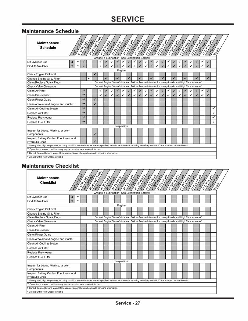
Maintenance Schedule
MaintenanceSchedule
#of
Loca
tions
#of
Pum
psAS
NEED
EDAf
ter F
irst 5
Hrs.
Daily
At25
Hour
sAt
50Ho
urs
At75
Hour
sAt
100
Hour
sAt
125
Hour
sAt
150
Hour
sAt
175
Hour
sAt
200
Hour
sAt
225
Hour
sAt
250
Hour
sAt
275
Hour
sAt
300
Hour
sAt
325
Hour
sAt
350
Hour
sAt
375
Hour
sAt
400
Hour
sAt
425
Hour
sAt
450
Hour
sAt
475
Hour
sAt
500
Hour
sYe
arly
Lift Cylinder End 4 ^ Bin/Lift Arm Pivot 2 ^
** ** ** ** ** ** ** **
* If heavy load, high temperature, or dusty condition service intervals are not specified, Ventrac recommends servicing more frequently at 1/2 the standard service interval.
Inspect for Loose, Missing, or Worn Components
Check Valve Clearance Consult Engine Owner's Manual; Follow Service Intervals for Heavy Loads and High Temperatures*Clean/Replace Spark Plugs Consult Engine Owner's Manual; Follow Service Intervals for Heavy Loads and High Temperatures*
** Operation in severe conditions may require more frequent service intervals.
InspectionReplace Fuel Filter
Clean Air FilterClean Pre-cleaner
Inspect Battery Cables, Fuel Lines, and Hydraulic Lines
Clean Air Cooling System
Grease & Lubrication: See Lubrication Section
Engine!
Check Engine Oil LevelChange Engine Oil & Filter ! *
Replace Air Filter
Clean Finger Guard
Replace Pre-cleaner
Clean area around engine and muffler
! Consult Engine Owner's Manual for engine oil information and complete servicing information
^ Grease Until Fresh Grease is visible
Maintenance Checklist
MaintenanceChecklist
#of
Loca
tions
#of
Pum
psAS
NEED
EDAf
ter F
irst 5
Hrs.
Daily
At25
Hour
sAt
50Ho
urs
At75
Hour
sAt
100
Hour
sAt
125
Hour
sAt
150
Hour
sAt
175
Hour
sAt
200
Hour
sAt
225
Hour
sAt
250
Hour
sAt
275
Hour
sAt
300
Hour
sAt
325
Hour
sAt
350
Hour
sAt
375
Hour
sAt
400
Hour
sAt
425
Hour
sAt
450
Hour
sAt
475
Hour
sAt
500
Hour
sYe
arly
Lift Cylinder End 4 ^Bin/Lift Arm Pivot 2 ^
! Consult Engine Owner's Manual for engine oil information and complete servicing information
^ Grease Until Fresh Grease is visible
Consult Engine Owner's Manual; Follow Service Intervals for Heavy Loads and High Temperatures*
Clean Air Filter
Replace Fuel FilterInspection
Inspect for Loose, Missing, or Worn ComponentsInspect Battery Cables, Fuel Lines, and Hydraulic Lines
Clean Pre-cleanerClean Finger Guard
* If heavy load, high temperature, or dusty condition service intervals are not specified, Ventrac recommends servicing more frequently at 1/2 the standard service interval.
** Operation in severe conditions may require more frequent service intervals.
Check Valve Clearance
Clean area around engine and mufflerClean Air Cooling SystemReplace Air FilterReplace Pre-cleaner
Clean/Replace Spark Plugs Consult Engine Owner's Manual; Follow Service Intervals for Heavy Loads and High Temperatures*
Grease & Lubrication: See Lubrication Section
Engine!
Check Engine Oil LevelChange Engine Oil & Filter ! *

Specifications - 28
SPECIFICATIONSDimensions
Overall Height . . . . . . . . . . . . . . . . . . . . . . . . . . . . . . . . . 53 inches (135 cm)Overall Length . . . . . . . . . . . . . . . . . . . . . . . . . . . . . . . . . 40 inches (102 cm)Overall Width . . . . . . . . . . . . . . . . . . . . . . . . . . . . . . . . . 65 inches (165 cm)Weight . . . . . . . . . . . . . . . . . . . . . . . . . . . . . . . . . . . . .525 pounds (238 kg)Capacity Recommended . . . . . . . . . . . . . . . . . . . . . . . . . . 13 cu. ft./10 bushel (0.37 m3) Maximum . . . . . . . . . . . . . . . . . . . . . . . . . . . . . 16 cu. ft./13 bushel (0.45 m3)Bin Lifting Height . . . . . . . . . . . . . . . . . . . . . . . . . . . . . . . 60 inches (152 cm)Hose Diameter . . . . . . . . . . . . . . . . . . . . . . . . . . . . . . . . . . . 8 inches (20 cm)
EngineManufacturer . . . . . . . . . . . . . . . . . . . . . . . . . . . . . . . . . . . . . . .VanguardModel Number . . . . . . . . . . . . . . . . . . . . . . . . . . . . . . . . . . . . . . . . . . 19Type . . . . . . . . . . . . . . . . . . . . . . . . . . . . . . . . . . . . . . . . . . . . GasolineCylinders . . . . . . . . . . . . . . . . . . . . . . . . . . . . . . . . . . . . . . . . . . . SingleEngine Gross Horse Power . . . . . . . . . . . . . . . . . . . . . . . . . . . . . . . . . 10 HpEngine Oil Capacity . . . . . . . . . . . . . . . . . . . . . . . . . . 26-28 ounces (0.77-0.83 L)Cooling System . . . . . . . . . . . . . . . . . . . . . . . . . . . . . . . . . . . . . Air CooledStarting . . . . . . . . . . . . . . . . . . . . . . . . . . . . . . . . . . . . . . . . . . . Electric
FeaturesStorage stands with caster wheelsHydraulic lift and dump.Hour meter.Handles on suction hose for clean-up.Window for viewing material level in collection bin.Collection bin vent deflector.
Power Unit RequirementsRecommended for use with KT4100 power units serial number 4100-*EC1501 and higher, KT4200 power units serial number 4200-*EB2555 and higher, and all KN4500 power units.Two sets of rear hydraulic quick couplers are required to operate the RV602 collection vacuum. If your power unit is not equipped with a 3-point hitch, order the rear hydraulic valve kit for your power unit. KT4100 and 4200 power units - Kit # 70.4088 KN4500 power units - Kit # 70.4126The RV602 collection vacuum can not be used on a power unit equipped with a Ventrac cab.The RV602 collection vacuum can not be used on a power unit equipped with a Ventrac canopy.The RV602 collection vacuum can not be used on a 4500Z power unit equipped with a propane kit.The RV602 collection vacuum can not be used on a 4500 power unit equipped with directional/hazard lights.

Illustrated Parts - 29 Use only original Ventrac replacement parts.
PARTSElectrical Diagram
To TractorGround Stud
To TractorCircuit Breaker
MLG
B
S
1
2
3
4
5
6
7
810
6
10
10
911
12
11
12
13
13
Ref. Description1 Ignition Switch2 Hour Meter3 Shut-Off Switch4 Engine Solenoid
5 20 Amp Fuse6 Battery Cable Connector7 12 Ga Red Wire - Supply8 18 Ga Red Wire9 14 Ga Green Wire W/Yellow Stripe -
Solenoid Trigger
10 14 Ga Black Wire - Ground11 14 Ga Brown Wire - Ignition Shut-Off12 Positive Battery Cable - Red13 Negative Battery Cable - Black
Refer to the Engine Controls & Electrical Components andBattery Cable Connector pages for part numbers and locations.
RV602 Main Harness - 32.0096Battery Cable Assembly Vac/Tractor - 32.0094Battery Cable Assembly Vac/Engine - 32.0095
PARTS
Illustrated Parts - 30 Use only original Ventrac replacement parts.
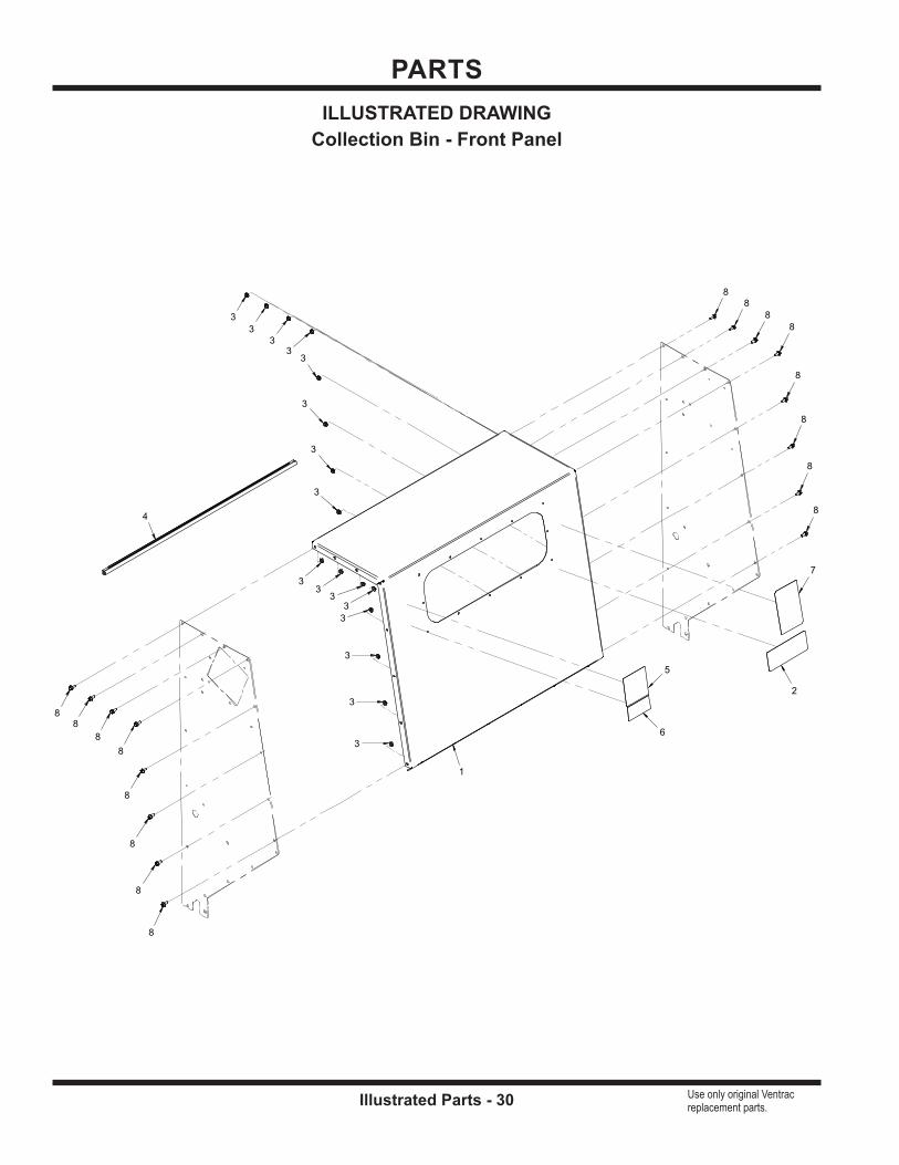
ILLUSTRATED DRAWINGCollection Bin - Front Panel
5
6
7
2
4
1
3
3
3
33
33
3
33
33
3
3
3
3
8
8
8
8
88
8
8
8
8
8
8
8
8
8
8

PARTS
Illustrated Parts - 31 Use only original Ventrac replacement parts.
REF. PART NO. DESCRIPTION QTY.1 . . . . . . . . . 60.1011 . . . . . . . . . . . . . . . . . . . .PANEL, COLLECTION BIN TOP/FRONT . . . . . . . . . . . . . . . . . . . . . . . . . . . . . . . . . . . . . . 1 2 . . . . . . . . . 00.0350 . . . . . . . . . . . . . . . . . . . .DECAL, MAINTENANCE RV602 . . . . . . . . . . . . . . . . . . . . . . . . . . . . . . . . . . . . . . . . . . . . . 1 3 . . . . . . . . . 99.SF04 . . . . . . . . . . . . . . . . . . .NUT, SF 1/4-20 USS . . . . . . . . . . . . . . . . . . . . . . . . . . . . . . . . . . . . . . . . . . . . . . . . . . . . . . 16 4 . . . . . . . . . 06.0049-35IN . . . . . . . . . . . . . . .TRIM, 7/16” BULB SEAL SIDE 1/16T X 35” . . . . . . . . . . . . . . . . . . . . . . . . . . . . . . . . . . . . . 1 5 . . . . . . . . . 00.0103 . . . . . . . . . . . . . . . . . . . .DECAL, HAZARD - HIGH PRESS. FLUID . . . . . . . . . . . . . . . . . . . . . . . . . . . . . . . . . . . . . 1 6 . . . . . . . . . 00.0220 . . . . . . . . . . . . . . . . . . . .DECAL, GENERAL SAFETY . . . . . . . . . . . . . . . . . . . . . . . . . . . . . . . . . . . . . . . . . . . . . . . . 1
7 . . . . . . . . . 00.0269 . . . . . . . . . . . . . . . . . . . .DECAL, COLLECTION SYSTEM RV600 . . . . . . . . . . . . . . . . . . . . . . . . . . . . . . . . . . . . . . 1 8 . . . . . . . . . 99.SF0405-1 . . . . . . . . . . . . . . . .BOLT, SMF 1/4-20 X 5/8 . . . . . . . . . . . . . . . . . . . . . . . . . . . . . . . . . . . . . . . . . . . . . . . . . . . 16
Collection Bin - Front Panel
PARTS
Illustrated Parts - 32 Use only original Ventrac replacement parts.
12
11
7
10
8
8
9
2
1
6
6
6
6
6
6
6
6
6
4
4
4
4
4
4
4
4
4
5
5
5
5
5
55
5
5
5
5
55
5
1313
13
13
13
13
13
13
13
13
13
13
1313
3
3
3
3
3
3
3
3
3
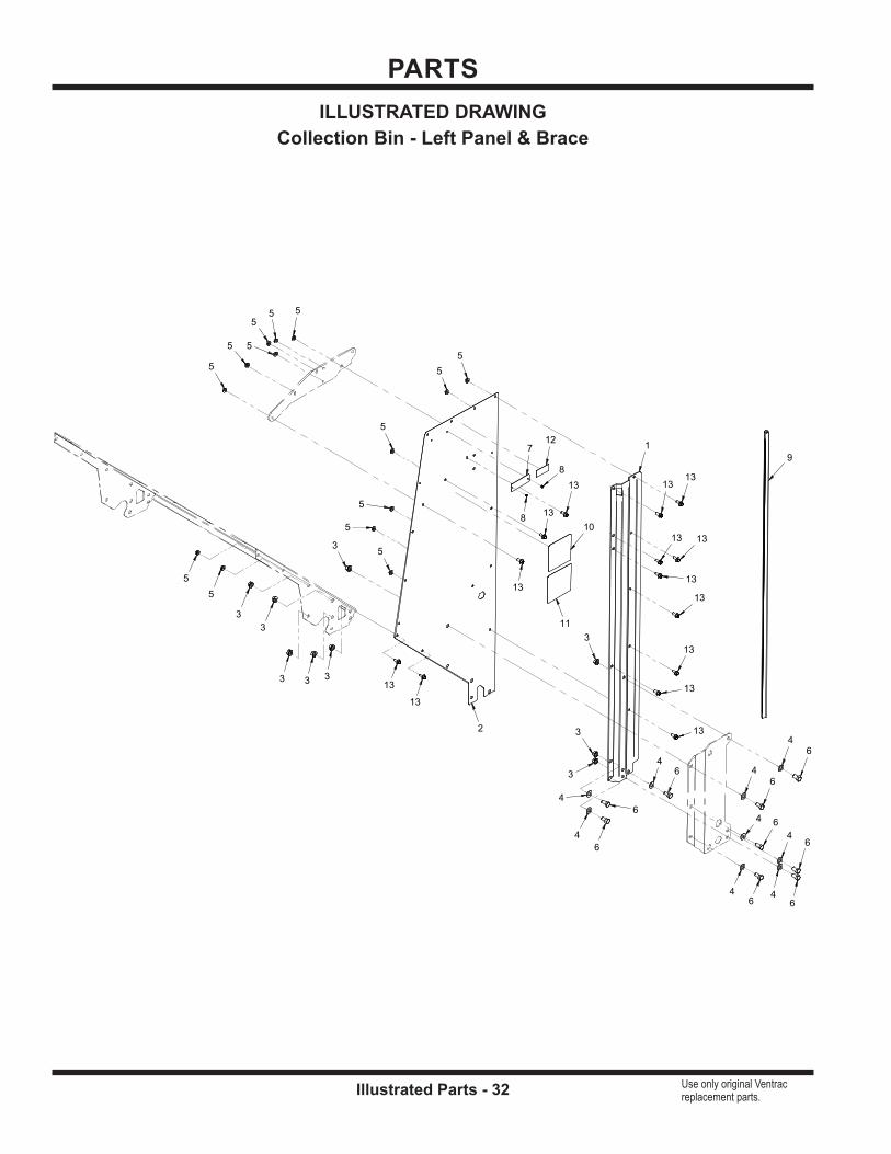
ILLUSTRATED DRAWINGCollection Bin - Left Panel & Brace

PARTS
Illustrated Parts - 33 Use only original Ventrac replacement parts.
REF. PART NO. DESCRIPTION QTY.1 . . . . . . . . . 64.1351 . . . . . . . . . . . . . . . . . . . .BRACE, BIN OUTER LEFT . . . . . . . . . . . . . . . . . . . . . . . . . . . . . . . . . . . . . . . . . . . . . . . . . 1 2 . . . . . . . . . 60.1010 . . . . . . . . . . . . . . . . . . . .PANEL, COLLECTION BIN LEFT . . . . . . . . . . . . . . . . . . . . . . . . . . . . . . . . . . . . . . . . . . . . 1 3 . . . . . . . . . 99.SF06 . . . . . . . . . . . . . . . . . . .NUT, SF 3/8-16 USS . . . . . . . . . . . . . . . . . . . . . . . . . . . . . . . . . . . . . . . . . . . . . . . . . . . . . . . 9 4 . . . . . . . . . 95.06 . . . . . . . . . . . . . . . . . . . . . .WASHER, FLAT 3/8 SAE . . . . . . . . . . . . . . . . . . . . . . . . . . . . . . . . . . . . . . . . . . . . . . . . . . . 9 5 . . . . . . . . . 99.SF04 . . . . . . . . . . . . . . . . . . .NUT, SF 1/4-20 USS . . . . . . . . . . . . . . . . . . . . . . . . . . . . . . . . . . . . . . . . . . . . . . . . . . . . . . 14 6 . . . . . . . . . 90.0606 . . . . . . . . . . . . . . . . . . . .BOLT, HEX 3/8-16 UNC X 3/4 . . . . . . . . . . . . . . . . . . . . . . . . . . . . . . . . . . . . . . . . . . . . . . . . 9
7 . . . . . . . . . 00.0128 . . . . . . . . . . . . . . . . . . . .PLATE, VENTRAC SERIAL NUMBER . . . . . . . . . . . . . . . . . . . . . . . . . . . . . . . . . . . . . . . . 1 8 . . . . . . . . . 04.0007 . . . . . . . . . . . . . . . . . . . .RIVET, POP DOME 1/8 X 1/8 S.S. . . . . . . . . . . . . . . . . . . . . . . . . . . . . . . . . . . . . . . . . . . . . 2 9 . . . . . . . . . 06.0049-42IN . . . . . . . . . . . . . . .TRIM, 7/16” BULB SEAL SIDE 1/16T X 42” . . . . . . . . . . . . . . . . . . . . . . . . . . . . . . . . . . . . . 1 10 . . . . . . . . 00.0267 . . . . . . . . . . . . . . . . . . . .DECAL, DANGER RV600 . . . . . . . . . . . . . . . . . . . . . . . . . . . . . . . . . . . . . . . . . . . . . . . . . . . 1 11 . . . . . . . . . 00.0102 . . . . . . . . . . . . . . . . . . . .DECAL, DANGER - PINCHING HAZARDS . . . . . . . . . . . . . . . . . . . . . . . . . . . . . . . . . . . . 1 12 . . . . . . . . 00.0100 . . . . . . . . . . . . . . . . . . . .DECAL, MADE IN USA . . . . . . . . . . . . . . . . . . . . . . . . . . . . . . . . . . . . . . . . . . . . . . . . . . . . . 1
13 . . . . . . . . 99.SF0405-1 . . . . . . . . . . . . . . . .BOLT, SMF 1/4-20 X 5/8 . . . . . . . . . . . . . . . . . . . . . . . . . . . . . . . . . . . . . . . . . . . . . . . . . . . 14
Collection Bin - Left Panel & Brace

PARTS
Illustrated Parts - 34 Use only original Ventrac replacement parts.
ILLUSTRATED DRAWINGCollection Bin - Right Panel & Brace
10
9
8
2
1
7
7
7
7
7
7
7
7
5
4
4
4
4
4
4 4
4
46
6
6 6
6
6
6
6
6
6
6
6
6
6
11
11
11
11
11
11
1111
11
11
11
1111
11
3
3
3
3 3
3
3
3
3
PARTS
Illustrated Parts - 35 Use only original Ventrac replacement parts.
REF. PART NO. DESCRIPTION QTY.1 . . . . . . . . . 64.1350 . . . . . . . . . . . . . . . . . . . .BRACKET, BIN OUTER RIGHT . . . . . . . . . . . . . . . . . . . . . . . . . . . . . . . . . . . . . . . . . . . . . . 1 2 . . . . . . . . . 60.1009 . . . . . . . . . . . . . . . . . . . .PANEL, COLLECTION BIN RIGHT . . . . . . . . . . . . . . . . . . . . . . . . . . . . . . . . . . . . . . . . . . . 1 3 . . . . . . . . . 99.SF06 . . . . . . . . . . . . . . . . . . .NUT, SF 3/8-16 USS . . . . . . . . . . . . . . . . . . . . . . . . . . . . . . . . . . . . . . . . . . . . . . . . . . . . . . . 9 4 . . . . . . . . . 95.06 . . . . . . . . . . . . . . . . . . . . . .WASHER, FLAT 3/8 SAE . . . . . . . . . . . . . . . . . . . . . . . . . . . . . . . . . . . . . . . . . . . . . . . . . . . 9 5 . . . . . . . . . 90.0608 . . . . . . . . . . . . . . . . . . . .BOLT, HEX 3/8-16 UNC X 1 . . . . . . . . . . . . . . . . . . . . . . . . . . . . . . . . . . . . . . . . . . . . . . . . . 1 6 . . . . . . . . . 99.SF04 . . . . . . . . . . . . . . . . . . .NUT, SF 1/4-20 USS . . . . . . . . . . . . . . . . . . . . . . . . . . . . . . . . . . . . . . . . . . . . . . . . . . . . . . 14
7 . . . . . . . . . 90.0606 . . . . . . . . . . . . . . . . . . . .BOLT, HEX 3/8-16 UNC X 3/4 . . . . . . . . . . . . . . . . . . . . . . . . . . . . . . . . . . . . . . . . . . . . . . . . 8 8 . . . . . . . . . 06.0049-42IN . . . . . . . . . . . . . . .TRIM, 7/16” BULB SEAL SIDE 1/16T X 42” . . . . . . . . . . . . . . . . . . . . . . . . . . . . . . . . . . . . . 1 9 . . . . . . . . . 00.0267 . . . . . . . . . . . . . . . . . . . .DECAL, DANGER RV600 . . . . . . . . . . . . . . . . . . . . . . . . . . . . . . . . . . . . . . . . . . . . . . . . . . . 1 10 . . . . . . . . 00.0102 . . . . . . . . . . . . . . . . . . . .DECAL, DANGER - PINCHING HAZARDS . . . . . . . . . . . . . . . . . . . . . . . . . . . . . . . . . . . . 1 11 . . . . . . . . . 99.SF0405-1 . . . . . . . . . . . . . . . .BOLT, SMF 1/4-20 X 5/8 . . . . . . . . . . . . . . . . . . . . . . . . . . . . . . . . . . . . . . . . . . . . . . . . . . . 14
Collection Bin - Right Panel & Brace

PARTS
Illustrated Parts - 36 Use only original Ventrac replacement parts.
2
1
5
5
55 5
55
55
55
5
4
4
4
44
4
44
44
4
4
33
3
33
3
6
6
66
6
6
ILLUSTRATED DRAWINGCollection Bin - Floor Panel & Front Window
PARTS
Illustrated Parts - 37 Use only original Ventrac replacement parts.
REF. PART NO. DESCRIPTION QTY.1 . . . . . . . . . 60.1014 . . . . . . . . . . . . . . . . . . . .PANEL, COLLECTION BIN FLOOR . . . . . . . . . . . . . . . . . . . . . . . . . . . . . . . . . . . . . . . . . . 1 2 . . . . . . . . . 44.0255 . . . . . . . . . . . . . . . . . . . .WINDOW, COLLECTION BIN . . . . . . . . . . . . . . . . . . . . . . . . . . . . . . . . . . . . . . . . . . . . . . . 1 3 . . . . . . . . . 99.SF04 . . . . . . . . . . . . . . . . . . .NUT, SF 1/4-20 USS . . . . . . . . . . . . . . . . . . . . . . . . . . . . . . . . . . . . . . . . . . . . . . . . . . . . . . . 6 4 . . . . . . . . . 99.K0062 . . . . . . . . . . . . . . . . . . .MACHINE SCREW, #10-32 X 1/2 . . . . . . . . . . . . . . . . . . . . . . . . . . . . . . . . . . . . . . . . . . . . 12 5 . . . . . . . . . 99.A1032N . . . . . . . . . . . . . . . . .LOCKNUT, NYLON 10-32 STAINLESS . . . . . . . . . . . . . . . . . . . . . . . . . . . . . . . . . . . . . . . 12 6 . . . . . . . . . 99.SF0405-1 . . . . . . . . . . . . . . . .BOLT, SMF 1/4-20 X 5/8 . . . . . . . . . . . . . . . . . . . . . . . . . . . . . . . . . . . . . . . . . . . . . . . . . . . . 6
Collection Bin - Floor Panel & Front Window

PARTS
Illustrated Parts - 38 Use only original Ventrac replacement parts.
24
14
14
1818
18
16
22
1927
28
26
1
1
2
2
20
20
20
20
21
21
21
3
23
23
2323
9
9
9
7
7
7
7
7
7
10
10
17
15
1313
11
11
11
11
6
6
6
6
6
6
6
6
6
6
6
6
6
4
4
8
8
25
25
12
12
12
12
55
5 5
5
55
55
5
55
5
ILLUSTRATED DRAWINGCollection Bin - Door & Latch (Serial # 01001 - 01369)

PARTS
Illustrated Parts - 39 Use only original Ventrac replacement parts.
REF. PART NO. DESCRIPTION QTY.1 . . . . . . . . . 64.1346 . . . . . . . . . . . . . . . . . . . .HINGE, LATCH RETAINER . . . . . . . . . . . . . . . . . . . . . . . . . . . . . . . . . . . . . . . . . . . . . . . . . 2 2 . . . . . . . . . 64.1347 . . . . . . . . . . . . . . . . . . . .MOUNT, COLLECTION BIN DOOR . . . . . . . . . . . . . . . . . . . . . . . . . . . . . . . . . . . . . . . . . . 2 3 . . . . . . . . . 64.1358 . . . . . . . . . . . . . . . . . . . .MOUNT, DOOR CYLINDER . . . . . . . . . . . . . . . . . . . . . . . . . . . . . . . . . . . . . . . . . . . . . . . . . 1 4 . . . . . . . . . 99.A06 . . . . . . . . . . . . . . . . . . . . .LOCKNUT, STOVER 3/8-16 USS . . . . . . . . . . . . . . . . . . . . . . . . . . . . . . . . . . . . . . . . . . . . 2 5 . . . . . . . . . 99.SF06 . . . . . . . . . . . . . . . . . . .NUT, SF 3/8-16 USS . . . . . . . . . . . . . . . . . . . . . . . . . . . . . . . . . . . . . . . . . . . . . . . . . . . . . . 13 6 . . . . . . . . . 95.06 . . . . . . . . . . . . . . . . . . . . . .WASHER, FLAT 3/8 SAE . . . . . . . . . . . . . . . . . . . . . . . . . . . . . . . . . . . . . . . . . . . . . . . . . . 13
7 . . . . . . . . . 90.0608 . . . . . . . . . . . . . . . . . . . .BOLT, HEX 3/8-16 UNC X 1 . . . . . . . . . . . . . . . . . . . . . . . . . . . . . . . . . . . . . . . . . . . . . . . . . 6 8 . . . . . . . . . 99.SF04 . . . . . . . . . . . . . . . . . . .NUT, SF 1/4-20 USS . . . . . . . . . . . . . . . . . . . . . . . . . . . . . . . . . . . . . . . . . . . . . . . . . . . . . . . 2 9 . . . . . . . . . 90.0606 . . . . . . . . . . . . . . . . . . . .BOLT, HEX 3/8-16 UNC X 3/4 . . . . . . . . . . . . . . . . . . . . . . . . . . . . . . . . . . . . . . . . . . . . . . . . 3 10 . . . . . . . . 90.0610 . . . . . . . . . . . . . . . . . . . .BOLT, HEX 3/8-16 UNC X 1-1/4 . . . . . . . . . . . . . . . . . . . . . . . . . . . . . . . . . . . . . . . . . . . . . . 2 11 . . . . . . . . . 95.05 . . . . . . . . . . . . . . . . . . . . . .WASHER, FLAT 5/16 SAE . . . . . . . . . . . . . . . . . . . . . . . . . . . . . . . . . . . . . . . . . . . . . . . . . . 4 12 . . . . . . . . 99.SF05 . . . . . . . . . . . . . . . . . . .NUT, SF 5/16-18 USS . . . . . . . . . . . . . . . . . . . . . . . . . . . . . . . . . . . . . . . . . . . . . . . . . . . . . . 4
13 . . . . . . . . 94.06 . . . . . . . . . . . . . . . . . . . . . .WASHER, FLAT 3/8 USS . . . . . . . . . . . . . . . . . . . . . . . . . . . . . . . . . . . . . . . . . . . . . . . . . . . 2 14 . . . . . . . . 05.0083 . . . . . . . . . . . . . . . . . . . .WASHER, PVC .375ID X .875 X .0625. . . . . . . . . . . . . . . . . . . . . . . . . . . . . . . . . . . . . . . . . 2 15 . . . . . . . . 90.0620 . . . . . . . . . . . . . . . . . . . .BOLT, HEX 3/8-16 UNC X 2-1/2 . . . . . . . . . . . . . . . . . . . . . . . . . . . . . . . . . . . . . . . . . . . . . . 1 16 . . . . . . . . 41.0048 . . . . . . . . . . . . . . . . . . . .SPRING, EXT. 1 OD X 6 . . . . . . . . . . . . . . . . . . . . . . . . . . . . . . . . . . . . . . . . . . . . . . . . . . . . 1 17 . . . . . . . . 90.0614 . . . . . . . . . . . . . . . . . . . .BOLT, HEX 3/8-16 UNC X 1-3/4 . . . . . . . . . . . . . . . . . . . . . . . . . . . . . . . . . . . . . . . . . . . . . . 1 18 . . . . . . . . 05.0119 . . . . . . . . . . . . . . . . . . . .WASHER, NYLON . . . . . . . . . . . . . . . . . . . . . . . . . . . . . . . . . . . . . . . . . . . . . . . . . . . . . . . . 3
19 . . . . . . . . 44.0253 . . . . . . . . . . . . . . . . . . . .SCREEN, COLLECTION OUTLET . . . . . . . . . . . . . . . . . . . . . . . . . . . . . . . . . . . . . . . . . . . 1 20 . . . . . . . . 64.1348 . . . . . . . . . . . . . . . . . . . .CLAMP, SIDE CURTAIN . . . . . . . . . . . . . . . . . . . . . . . . . . . . . . . . . . . . . . . . . . . . . . . . . . . . 4 21 . . . . . . . . 64.1349 . . . . . . . . . . . . . . . . . . . .CLAMP, TOP CURTAIN . . . . . . . . . . . . . . . . . . . . . . . . . . . . . . . . . . . . . . . . . . . . . . . . . . . . 3 22 . . . . . . . . 44.0252 . . . . . . . . . . . . . . . . . . . .CANVAS, COLLECTION OUTLET . . . . . . . . . . . . . . . . . . . . . . . . . . . . . . . . . . . . . . . . . . . 1 23 . . . . . . . . 90.0510 . . . . . . . . . . . . . . . . . . . .BOLT, HEX 5/16-18 UNC X 1-1/4” . . . . . . . . . . . . . . . . . . . . . . . . . . . . . . . . . . . . . . . . . . . . 4 24 . . . . . . . . 00.0189 . . . . . . . . . . . . . . . . . . . .DECAL, VENTRAC ORBITAL . . . . . . . . . . . . . . . . . . . . . . . . . . . . . . . . . . . . . . . . . . . . . . . 1
25 . . . . . . . . 99.SF0405-1 . . . . . . . . . . . . . . . .BOLT, SMF 1/4-20 X 5/8 . . . . . . . . . . . . . . . . . . . . . . . . . . . . . . . . . . . . . . . . . . . . . . . . . . . . 2 26 . . . . . . . . 64.1345 . . . . . . . . . . . . . . . . . . . .LATCH, BIN DOOR RV . . . . . . . . . . . . . . . . . . . . . . . . . . . . . . . . . . . . . . . . . . . . . . . . . . . . . 1 27 . . . . . . . . 60.1012 . . . . . . . . . . . . . . . . . . . .DOOR, COLLECTION BIN . . . . . . . . . . . . . . . . . . . . . . . . . . . . . . . . . . . . . . . . . . . . . . . . . . 1 28 . . . . . . . . 62.1278 . . . . . . . . . . . . . . . . . . . .FRAME, COLLECTION DOOR . . . . . . . . . . . . . . . . . . . . . . . . . . . . . . . . . . . . . . . . . . . . . . 1
Collection Bin - Door & Latch (Serial # 01001 - 01369)
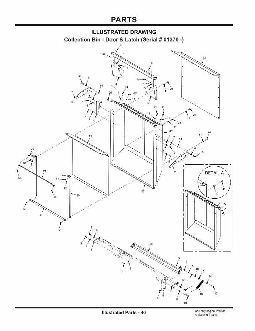
PARTS
Illustrated Parts - 40 Use only original Ventrac replacement parts.
A
DETAIL A
14
14
18
18
18
16
22
19
27
28
26
1
1
2
2
3
20
20
21
21
23
23
23
23
24
24
24
24
9
9
9
7
7
7
7
7
7
10
10
17
15
13
13
11
11
11
11
11
11
11
11
6
6
6
6
6
6
6
6
6
6
6
6
6
4
4
8
8
25
25
12
12
12
12
12
12
12
12
5
5
55
5
5
5
5
5
5
5
55
40
41
ILLUSTRATED DRAWINGCollection Bin - Door & Latch (Serial # 01370 -)
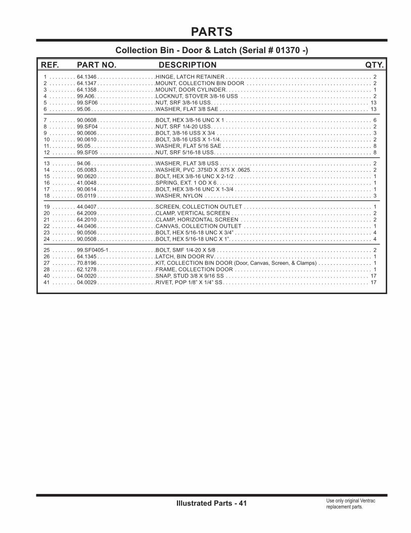
PARTS
Illustrated Parts - 41 Use only original Ventrac replacement parts.
REF. PART NO. DESCRIPTION QTY.1 . . . . . . . . . 64.1346 . . . . . . . . . . . . . . . . . . . .HINGE, LATCH RETAINER . . . . . . . . . . . . . . . . . . . . . . . . . . . . . . . . . . . . . . . . . . . . . . . . . 2 2 . . . . . . . . . 64.1347 . . . . . . . . . . . . . . . . . . . .MOUNT, COLLECTION BIN DOOR . . . . . . . . . . . . . . . . . . . . . . . . . . . . . . . . . . . . . . . . . . 2 3 . . . . . . . . . 64.1358 . . . . . . . . . . . . . . . . . . . .MOUNT, DOOR CYLINDER . . . . . . . . . . . . . . . . . . . . . . . . . . . . . . . . . . . . . . . . . . . . . . . . . 1 4 . . . . . . . . . 99.A06 . . . . . . . . . . . . . . . . . . . . .LOCKNUT, STOVER 3/8-16 USS . . . . . . . . . . . . . . . . . . . . . . . . . . . . . . . . . . . . . . . . . . . . 2 5 . . . . . . . . . 99.SF06 . . . . . . . . . . . . . . . . . . .NUT, SRF 3/8-16 USS . . . . . . . . . . . . . . . . . . . . . . . . . . . . . . . . . . . . . . . . . . . . . . . . . . . . . 13 6 . . . . . . . . . 95.06 . . . . . . . . . . . . . . . . . . . . . .WASHER, FLAT 3/8 SAE . . . . . . . . . . . . . . . . . . . . . . . . . . . . . . . . . . . . . . . . . . . . . . . . . . 13
7 . . . . . . . . . 90.0608 . . . . . . . . . . . . . . . . . . . .BOLT, HEX 3/8-16 UNC X 1 . . . . . . . . . . . . . . . . . . . . . . . . . . . . . . . . . . . . . . . . . . . . . . . . . 6 8 . . . . . . . . . 99.SF04 . . . . . . . . . . . . . . . . . . .NUT, SRF 1/4-20 USS . . . . . . . . . . . . . . . . . . . . . . . . . . . . . . . . . . . . . . . . . . . . . . . . . . . . . . 2 9 . . . . . . . . . 90.0606 . . . . . . . . . . . . . . . . . . . .BOLT, 3/8-16 USS X 3/4 . . . . . . . . . . . . . . . . . . . . . . . . . . . . . . . . . . . . . . . . . . . . . . . . . . . . 3 10 . . . . . . . . 90.0610 . . . . . . . . . . . . . . . . . . . .BOLT, 3/8-16 USS X 1-1/4 . . . . . . . . . . . . . . . . . . . . . . . . . . . . . . . . . . . . . . . . . . . . . . . . . . . 2 11 . . . . . . . . . 95.05 . . . . . . . . . . . . . . . . . . . . . .WASHER, FLAT 5/16 SAE . . . . . . . . . . . . . . . . . . . . . . . . . . . . . . . . . . . . . . . . . . . . . . . . . . 8 12 . . . . . . . . 99.SF05 . . . . . . . . . . . . . . . . . . .NUT, SRF 5/16-18 USS . . . . . . . . . . . . . . . . . . . . . . . . . . . . . . . . . . . . . . . . . . . . . . . . . . . . . 8
13 . . . . . . . . 94.06 . . . . . . . . . . . . . . . . . . . . . .WASHER, FLAT 3/8 USS . . . . . . . . . . . . . . . . . . . . . . . . . . . . . . . . . . . . . . . . . . . . . . . . . . . 2 14 . . . . . . . . 05.0083 . . . . . . . . . . . . . . . . . . . .WASHER, PVC .375ID X .875 X .0625. . . . . . . . . . . . . . . . . . . . . . . . . . . . . . . . . . . . . . . . . 2 15 . . . . . . . . 90.0620 . . . . . . . . . . . . . . . . . . . .BOLT, HEX 3/8-16 UNC X 2-1/2 . . . . . . . . . . . . . . . . . . . . . . . . . . . . . . . . . . . . . . . . . . . . . . 1 16 . . . . . . . . 41.0048 . . . . . . . . . . . . . . . . . . . .SPRING, EXT. 1 OD X 6 . . . . . . . . . . . . . . . . . . . . . . . . . . . . . . . . . . . . . . . . . . . . . . . . . . . . 1 17 . . . . . . . . 90.0614 . . . . . . . . . . . . . . . . . . . .BOLT, HEX 3/8-16 UNC X 1-3/4 . . . . . . . . . . . . . . . . . . . . . . . . . . . . . . . . . . . . . . . . . . . . . . 1 18 . . . . . . . . 05.0119 . . . . . . . . . . . . . . . . . . . .WASHER, NYLON . . . . . . . . . . . . . . . . . . . . . . . . . . . . . . . . . . . . . . . . . . . . . . . . . . . . . . . . 3
19 . . . . . . . . 44.0407 . . . . . . . . . . . . . . . . . . . .SCREEN, COLLECTION OUTLET . . . . . . . . . . . . . . . . . . . . . . . . . . . . . . . . . . . . . . . . . . . 1 20 . . . . . . . . 64.2009 . . . . . . . . . . . . . . . . . . . .CLAMP, VERTICAL SCREEN . . . . . . . . . . . . . . . . . . . . . . . . . . . . . . . . . . . . . . . . . . . . . . . 2 21 . . . . . . . . 64.2010 . . . . . . . . . . . . . . . . . . . .CLAMP, HORIZONTAL SCREEN . . . . . . . . . . . . . . . . . . . . . . . . . . . . . . . . . . . . . . . . . . . . 2 22 . . . . . . . . 44.0406 . . . . . . . . . . . . . . . . . . . .CANVAS, COLLECTION OUTLET . . . . . . . . . . . . . . . . . . . . . . . . . . . . . . . . . . . . . . . . . . . 1 23 . . . . . . . . 90.0506 . . . . . . . . . . . . . . . . . . . .BOLT, HEX 5/16-18 UNC X 3/4” . . . . . . . . . . . . . . . . . . . . . . . . . . . . . . . . . . . . . . . . . . . . . . 4 24 . . . . . . . . 90.0508 . . . . . . . . . . . . . . . . . . . .BOLT, HEX 5/16-18 UNC X 1”. . . . . . . . . . . . . . . . . . . . . . . . . . . . . . . . . . . . . . . . . . . . . . . . 4
25 . . . . . . . . 99.SF0405-1 . . . . . . . . . . . . . . . .BOLT, SMF 1/4-20 X 5/8 . . . . . . . . . . . . . . . . . . . . . . . . . . . . . . . . . . . . . . . . . . . . . . . . . . . . 2 26 . . . . . . . . 64.1345 . . . . . . . . . . . . . . . . . . . .LATCH, BIN DOOR RV . . . . . . . . . . . . . . . . . . . . . . . . . . . . . . . . . . . . . . . . . . . . . . . . . . . . . 1 27 . . . . . . . . 70.8196 . . . . . . . . . . . . . . . . . . . .KIT, COLLECTION BIN DOOR (Door, Canvas, Screen, & Clamps) . . . . . . . . . . . . . . . . . . 1 28 . . . . . . . . 62.1278 . . . . . . . . . . . . . . . . . . . .FRAME, COLLECTION DOOR . . . . . . . . . . . . . . . . . . . . . . . . . . . . . . . . . . . . . . . . . . . . . . 1 40 . . . . . . . . 04.0020 . . . . . . . . . . . . . . . . . . . .SNAP, STUD 3/8 X 9/16 SS . . . . . . . . . . . . . . . . . . . . . . . . . . . . . . . . . . . . . . . . . . . . . . . . 17 41 . . . . . . . . 04.0029 . . . . . . . . . . . . . . . . . . . .RIVET, POP 1/8” X 1/4” SS . . . . . . . . . . . . . . . . . . . . . . . . . . . . . . . . . . . . . . . . . . . . . . . . . 17
Collection Bin - Door & Latch (Serial # 01370 -)
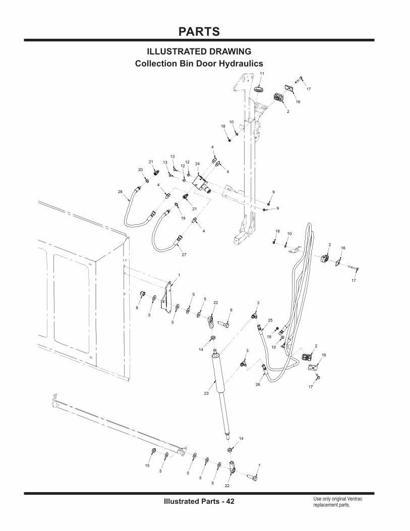
PARTS
Illustrated Parts - 42 Use only original Ventrac replacement parts.
11
19
20
25
26
27
28
21
21
23
24
4
4
4
4
3
3
22
22
16
16
16
2
2
2
1
1313
17
17
17
7
6
1212
10
10
10
5
5
5
5
55
5
5
18
18
18
8
14
14
15
9
9
ILLUSTRATED DRAWINGCollection Bin Door Hydraulics

PARTS
Illustrated Parts - 43 Use only original Ventrac replacement parts.
REF. PART NO. DESCRIPTION QTY.1 . . . . . . . . . 64.1358 . . . . . . . . . . . . . . . . . . . .MOUNT, DOOR CYLINDER . . . . . . . . . . . . . . . . . . . . . . . . . . . . . . . . . . . . . . . . . . . . . . . . . 1 2 . . . . . . . . . 44.0256 . . . . . . . . . . . . . . . . . . . .CLAMP, HYD HOSE 12.7MM ID GRN . . . . . . . . . . . . . . . . . . . . . . . . . . . . . . . . . . . . . . . . . 3 3 . . . . . . . . . 25.6801-06-06 . . . . . . . . . . . . . . .FITTING, 90 ME 3/8 X 3/8 . . . . . . . . . . . . . . . . . . . . . . . . . . . . . . . . . . . . . . . . . . . . . . . . . . . 2 4 . . . . . . . . . 25.6400-06-06 . . . . . . . . . . . . . . .FITTING, M CONN 3/8 X 3/8 . . . . . . . . . . . . . . . . . . . . . . . . . . . . . . . . . . . . . . . . . . . . . . . . 4 5 . . . . . . . . . 95.10 . . . . . . . . . . . . . . . . . . . . . .WASHER, FLAT 5/8 SAE . . . . . . . . . . . . . . . . . . . . . . . . . . . . . . . . . . . . . . . . . . . . . . . . . . . 8 6 . . . . . . . . . 91.1018 . . . . . . . . . . . . . . . . . . . .BOLT, HEX 5/8-18 UNF X 2-1/4 . . . . . . . . . . . . . . . . . . . . . . . . . . . . . . . . . . . . . . . . . . . . . . 1
7 . . . . . . . . . 91.1016 . . . . . . . . . . . . . . . . . . . .BOLT, HEX 5/8-18 UNF X 2 . . . . . . . . . . . . . . . . . . . . . . . . . . . . . . . . . . . . . . . . . . . . . . . . . 1 8 . . . . . . . . . 99.A10NFN . . . . . . . . . . . . . . . . .LOCKNUT, NYLON 5/8-18 SAE ZP . . . . . . . . . . . . . . . . . . . . . . . . . . . . . . . . . . . . . . . . . . . 1 9 . . . . . . . . . 99.SF04 . . . . . . . . . . . . . . . . . . .NUT, SF 1/4-20 USS . . . . . . . . . . . . . . . . . . . . . . . . . . . . . . . . . . . . . . . . . . . . . . . . . . . . . . . 2 10 . . . . . . . . 95.05 . . . . . . . . . . . . . . . . . . . . . .WASHER, FLAT 5/16 SAE . . . . . . . . . . . . . . . . . . . . . . . . . . . . . . . . . . . . . . . . . . . . . . . . . . 3 11 . . . . . . . . . 05.0036 . . . . . . . . . . . . . . . . . . . .GROMMET, 1 1/2ID,2 1/8OD,9/16T . . . . . . . . . . . . . . . . . . . . . . . . . . . . . . . . . . . . . . . . . . . 1 12 . . . . . . . . 95.04 . . . . . . . . . . . . . . . . . . . . . .WASHER, FLAT 1/4 SAE . . . . . . . . . . . . . . . . . . . . . . . . . . . . . . . . . . . . . . . . . . . . . . . . . . . 2
13 . . . . . . . . 90.0414 . . . . . . . . . . . . . . . . . . . .BOLT, HEX 1/4-20 UNC X 1-3/4” . . . . . . . . . . . . . . . . . . . . . . . . . . . . . . . . . . . . . . . . . . . . . 2 14 . . . . . . . . 99.E0011 . . . . . . . . . . . . . . . . . . .NUT, JAM 5/8 SAE . . . . . . . . . . . . . . . . . . . . . . . . . . . . . . . . . . . . . . . . . . . . . . . . . . . . . . . . 2 15 . . . . . . . . 99.E0092 . . . . . . . . . . . . . . . . . . .NUT, JAM 5/8-18 SAE LOCKING . . . . . . . . . . . . . . . . . . . . . . . . . . . . . . . . . . . . . . . . . . . . . 1 16 . . . . . . . . 44.0229 . . . . . . . . . . . . . . . . . . . .COVER PLATE, 2D GROUP . . . . . . . . . . . . . . . . . . . . . . . . . . . . . . . . . . . . . . . . . . . . . . . . 3 17 . . . . . . . . 90.0518 . . . . . . . . . . . . . . . . . . . .BOLT, HEX 5/16-18 UNC X 2-1/4” . . . . . . . . . . . . . . . . . . . . . . . . . . . . . . . . . . . . . . . . . . . . 3 18 . . . . . . . . 99.A05 . . . . . . . . . . . . . . . . . . . . .LOCKNUT, STOVER 5/16-18 USS . . . . . . . . . . . . . . . . . . . . . . . . . . . . . . . . . . . . . . . . . . . 3
19 . . . . . . . . 05.0116 . . . . . . . . . . . . . . . . . . . .WASHER, .544 ID X .817 X .14 RED . . . . . . . . . . . . . . . . . . . . . . . . . . . . . . . . . . . . . . . . . . 1 20 . . . . . . . . 05.0117 . . . . . . . . . . . . . . . . . . . .WASHER, .544 ID X .817 X .14 YEL . . . . . . . . . . . . . . . . . . . . . . . . . . . . . . . . . . . . . . . . . . 1 21 . . . . . . . . 23.0104 . . . . . . . . . . . . . . . . . . . .COUPLER, HYDRAULIC QUICK - 1/4 MALE . . . . . . . . . . . . . . . . . . . . . . . . . . . . . . . . . . . 2 22 . . . . . . . . 43.010 . . . . . . . . . . . . . . . . . . . . .ROD END, 5/8 SPHERICAL . . . . . . . . . . . . . . . . . . . . . . . . . . . . . . . . . . . . . . . . . . . . . . . . . 4 23 . . . . . . . . 23.0148 . . . . . . . . . . . . . . . . . . . .CYLINDER, 1-1/2” X 8” VAC . . . . . . . . . . . . . . . . . . . . . . . . . . . . . . . . . . . . . . . . . . . . . . . . . 1 24 . . . . . . . . 23.0149 . . . . . . . . . . . . . . . . . . . .VALVE, DOUBLE RELIEF (Serial # 01001-01239) . . . . . . . . . . . . . . . . . . . . . . . . . . . . . . . 1 24 . . . . . . . . 23.0178 . . . . . . . . . . . . . . . . . . . .VALVE, DOUBLE RELIEF (Serial # 01240-) . . . . . . . . . . . . . . . . . . . . . . . . . . . . . . . . . . . . 1
25 . . . . . . . . 20.0279 . . . . . . . . . . . . . . . . . . . .HOSE, 1/4X94.00 SAE 100R17AR . . . . . . . . . . . . . . . . . . . . . . . . . . . . . . . . . . . . . . . . . . . . 1 26 . . . . . . . . 20.0280 . . . . . . . . . . . . . . . . . . . .HOSE, 1/4X84.00 SAE 100R17AR . . . . . . . . . . . . . . . . . . . . . . . . . . . . . . . . . . . . . . . . . . . . 1 27 . . . . . . . . 20.0283 . . . . . . . . . . . . . . . . . . . .HOSE, 1/4X25.00 SAE 100R17AR . . . . . . . . . . . . . . . . . . . . . . . . . . . . . . . . . . . . . . . . . . . . 1 28 . . . . . . . . 20.0283 . . . . . . . . . . . . . . . . . . . .HOSE, 1/4X25.00 SAE 100R17AR . . . . . . . . . . . . . . . . . . . . . . . . . . . . . . . . . . . . . . . . . . . . 1
Collection Bin Door Hydraulics

PARTS
Illustrated Parts - 44 Use only original Ventrac replacement parts.
22
7
7
7
7
20
20
15
15
6
6
5
5
8
8
9
9
2
1
4
3
10
10
11
11
21
25
25
25
25
19
19
19
19
12
12
16
16
16
16
16
16
24
24
24
24
18
18
18
18
18
18
18
18
14
14
14
14
14
14
14
14
14
14
1414
14
14
14
1414
14
14
1414
14
14
141313
23
23
23
23
23
23 27
27
27
26
26
26
17 17
17
17
ILLUSTRATED DRAWINGMain Frame & Collection Bin Lift Arm Frame

PARTS
Illustrated Parts - 45 Use only original Ventrac replacement parts.
REF. PART NO. DESCRIPTION QTY.1 . . . . . . . . . 62.1396 . . . . . . . . . . . . . . . . . . . .FRAME, MAIN . . . . . . . . . . . . . . . . . . . . . . . . . . . . . . . . . . . . . . . . . . . . . . . . . . . . . . . . . . . . 1 2 . . . . . . . . . 62.1283 . . . . . . . . . . . . . . . . . . . .FRAME, LIFT ARM RV600 . . . . . . . . . . . . . . . . . . . . . . . . . . . . . . . . . . . . . . . . . . . . . . . . . . 1 3 . . . . . . . . . 64.1353 . . . . . . . . . . . . . . . . . . . .MOUNT, BIN LIFTING LEFT . . . . . . . . . . . . . . . . . . . . . . . . . . . . . . . . . . . . . . . . . . . . . . . . 1 4 . . . . . . . . . 64.1352 . . . . . . . . . . . . . . . . . . . .MOUNT, BIN LIFTING RIGHT . . . . . . . . . . . . . . . . . . . . . . . . . . . . . . . . . . . . . . . . . . . . . . . 1 5 . . . . . . . . . 43.010L . . . . . . . . . . . . . . . . . . . .ROD END, 5/8 SPHERICAL . . . . . . . . . . . . . . . . . . . . . . . . . . . . . . . . . . . . . . . . . . . . . . . . . 2 6 . . . . . . . . . 43.010 . . . . . . . . . . . . . . . . . . . . .ROD END, 5/8 SPHERICAL . . . . . . . . . . . . . . . . . . . . . . . . . . . . . . . . . . . . . . . . . . . . . . . . . 2
7 . . . . . . . . . 05.0118 . . . . . . . . . . . . . . . . . . . .BUMPER, RUBBE CYLINDRICAL . . . . . . . . . . . . . . . . . . . . . . . . . . . . . . . . . . . . . . . . . . . 4 8 . . . . . . . . . 50.0046 . . . . . . . . . . . . . . . . . . . .TUBE, AXLE FRONT ROLLER . . . . . . . . . . . . . . . . . . . . . . . . . . . . . . . . . . . . . . . . . . . . . . 2 9 . . . . . . . . . 50.0047 . . . . . . . . . . . . . . . . . . . .ROLLER, FRONT 3” DIA X 3-1/2” . . . . . . . . . . . . . . . . . . . . . . . . . . . . . . . . . . . . . . . . . . . . 2 10 . . . . . . . . 64.1362 . . . . . . . . . . . . . . . . . . . .RETAINER, LIFT ARM HINGE . . . . . . . . . . . . . . . . . . . . . . . . . . . . . . . . . . . . . . . . . . . . . . . 2 11 . . . . . . . . . 64.1437 . . . . . . . . . . . . . . . . . . . .BRACKET, HOSE BLOCK HOLDER . . . . . . . . . . . . . . . . . . . . . . . . . . . . . . . . . . . . . . . . . . 2 12 . . . . . . . . 90.0636 . . . . . . . . . . . . . . . . . . . .BOLT, 3/8-16 USS X 4-1/2 . . . . . . . . . . . . . . . . . . . . . . . . . . . . . . . . . . . . . . . . . . . . . . . . . . . 2
13 . . . . . . . . 99.A06 . . . . . . . . . . . . . . . . . . . . .LOCKNUT, STOVER 3/8-16 USS . . . . . . . . . . . . . . . . . . . . . . . . . . . . . . . . . . . . . . . . . . . . 2 14 . . . . . . . . 95.10 . . . . . . . . . . . . . . . . . . . . . .WASHER, FLAT 5/8 SAE . . . . . . . . . . . . . . . . . . . . . . . . . . . . . . . . . . . . . . . . . . . . . . . . . . 24 15 . . . . . . . . 42.0538 . . . . . . . . . . . . . . . . . . . .ROD, THREAD 5/8-18 X 30 RH/LH . . . . . . . . . . . . . . . . . . . . . . . . . . . . . . . . . . . . . . . . . . . 2 16 . . . . . . . . 91.1018 . . . . . . . . . . . . . . . . . . . .BOLT, HEX 5/8-18 UNF X 2-1/4 . . . . . . . . . . . . . . . . . . . . . . . . . . . . . . . . . . . . . . . . . . . . . . 6 17 . . . . . . . . 99.SF06 . . . . . . . . . . . . . . . . . . .NUT, SF 3/8-16 USS . . . . . . . . . . . . . . . . . . . . . . . . . . . . . . . . . . . . . . . . . . . . . . . . . . . . . . . 4 18 . . . . . . . . 95.06 . . . . . . . . . . . . . . . . . . . . . .WASHER, FLAT 3/8 SAE . . . . . . . . . . . . . . . . . . . . . . . . . . . . . . . . . . . . . . . . . . . . . . . . . . . 8
19 . . . . . . . . 90.0608 . . . . . . . . . . . . . . . . . . . .BOLT, HEX 3/8-16 UNC X 1 . . . . . . . . . . . . . . . . . . . . . . . . . . . . . . . . . . . . . . . . . . . . . . . . . 4 20 . . . . . . . . 29.GF0001 . . . . . . . . . . . . . . . . .GREASE FTG, 1/4 SAE ST . . . . . . . . . . . . . . . . . . . . . . . . . . . . . . . . . . . . . . . . . . . . . . . . . 2 21 . . . . . . . . 64.1454 . . . . . . . . . . . . . . . . . . . .SUPPORT, CYLINDER LOCKOUT . . . . . . . . . . . . . . . . . . . . . . . . . . . . . . . . . . . . . . . . . . . 1 22 . . . . . . . . 03.0009 . . . . . . . . . . . . . . . . . . . .PIN, SAFETY SNAP 1/4 X 1-3/8 . . . . . . . . . . . . . . . . . . . . . . . . . . . . . . . . . . . . . . . . . . . . . . 1 23 . . . . . . . . 99.A10NFN . . . . . . . . . . . . . . . . .LOCKNUT, NYLON 5/8-18 SAE ZP . . . . . . . . . . . . . . . . . . . . . . . . . . . . . . . . . . . . . . . . . . . 6 24 . . . . . . . . 95.05 . . . . . . . . . . . . . . . . . . . . . .WASHER, FLAT 5/16 SAE . . . . . . . . . . . . . . . . . . . . . . . . . . . . . . . . . . . . . . . . . . . . . . . . . . 4
25 . . . . . . . . 90.0504 . . . . . . . . . . . . . . . . . . . .BOLT, HEX 5/16-18 UNC X 1/2” . . . . . . . . . . . . . . . . . . . . . . . . . . . . . . . . . . . . . . . . . . . . . . 4 26 . . . . . . . . 99.E0090 . . . . . . . . . . . . . . . . . . .NUT, JAM 5/8-18 SAE LH . . . . . . . . . . . . . . . . . . . . . . . . . . . . . . . . . . . . . . . . . . . . . . . . . . . 3 27 . . . . . . . . 99.E0011 . . . . . . . . . . . . . . . . . . .NUT, JAM 5/8 SAE . . . . . . . . . . . . . . . . . . . . . . . . . . . . . . . . . . . . . . . . . . . . . . . . . . . . . . . . 3
Main Frame & Collection Bin Lift Arm Frame
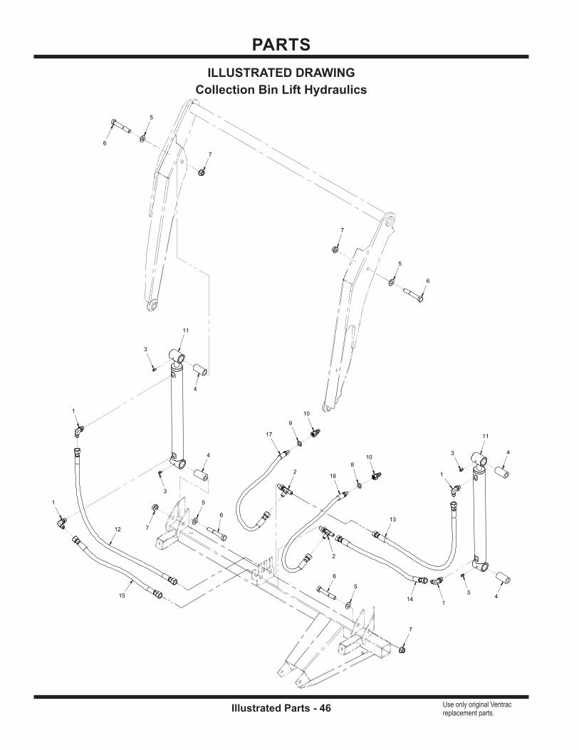
PARTS
Illustrated Parts - 46 Use only original Ventrac replacement parts.
ILLUSTRATED DRAWINGCollection Bin Lift Hydraulics
8
9
1213
1415
16
17
10
10
11
11
2
2
1
1
1
1
3
3
3
3
4
4
4
4
6
6
6
6
5
5
5
5
7
7
7
7
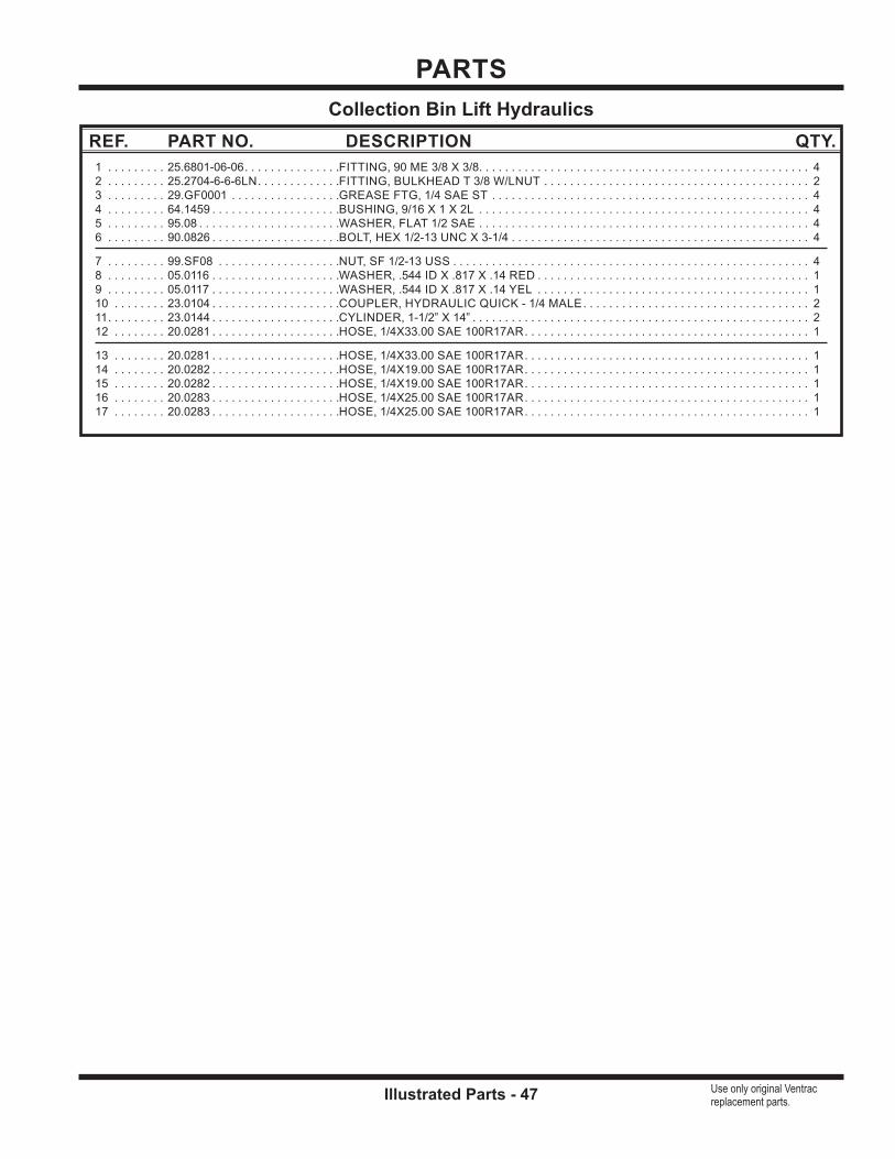
PARTS
Illustrated Parts - 47 Use only original Ventrac replacement parts.
REF. PART NO. DESCRIPTION QTY.1 . . . . . . . . . 25.6801-06-06 . . . . . . . . . . . . . . .FITTING, 90 ME 3/8 X 3/8 . . . . . . . . . . . . . . . . . . . . . . . . . . . . . . . . . . . . . . . . . . . . . . . . . . . 4 2 . . . . . . . . . 25.2704-6-6-6LN . . . . . . . . . . . . .FITTING, BULKHEAD T 3/8 W/LNUT . . . . . . . . . . . . . . . . . . . . . . . . . . . . . . . . . . . . . . . . . 2 3 . . . . . . . . . 29.GF0001 . . . . . . . . . . . . . . . . .GREASE FTG, 1/4 SAE ST . . . . . . . . . . . . . . . . . . . . . . . . . . . . . . . . . . . . . . . . . . . . . . . . . 4 4 . . . . . . . . . 64.1459 . . . . . . . . . . . . . . . . . . . .BUSHING, 9/16 X 1 X 2L . . . . . . . . . . . . . . . . . . . . . . . . . . . . . . . . . . . . . . . . . . . . . . . . . . . 4 5 . . . . . . . . . 95.08 . . . . . . . . . . . . . . . . . . . . . .WASHER, FLAT 1/2 SAE . . . . . . . . . . . . . . . . . . . . . . . . . . . . . . . . . . . . . . . . . . . . . . . . . . . 4 6 . . . . . . . . . 90.0826 . . . . . . . . . . . . . . . . . . . .BOLT, HEX 1/2-13 UNC X 3-1/4 . . . . . . . . . . . . . . . . . . . . . . . . . . . . . . . . . . . . . . . . . . . . . . 4
7 . . . . . . . . . 99.SF08 . . . . . . . . . . . . . . . . . . .NUT, SF 1/2-13 USS . . . . . . . . . . . . . . . . . . . . . . . . . . . . . . . . . . . . . . . . . . . . . . . . . . . . . . . 4 8 . . . . . . . . . 05.0116 . . . . . . . . . . . . . . . . . . . .WASHER, .544 ID X .817 X .14 RED . . . . . . . . . . . . . . . . . . . . . . . . . . . . . . . . . . . . . . . . . . 1 9 . . . . . . . . . 05.0117 . . . . . . . . . . . . . . . . . . . .WASHER, .544 ID X .817 X .14 YEL . . . . . . . . . . . . . . . . . . . . . . . . . . . . . . . . . . . . . . . . . . 1 10 . . . . . . . . 23.0104 . . . . . . . . . . . . . . . . . . . .COUPLER, HYDRAULIC QUICK - 1/4 MALE . . . . . . . . . . . . . . . . . . . . . . . . . . . . . . . . . . . 2 11 . . . . . . . . . 23.0144 . . . . . . . . . . . . . . . . . . . .CYLINDER, 1-1/2” X 14” . . . . . . . . . . . . . . . . . . . . . . . . . . . . . . . . . . . . . . . . . . . . . . . . . . . . 2 12 . . . . . . . . 20.0281 . . . . . . . . . . . . . . . . . . . .HOSE, 1/4X33.00 SAE 100R17AR . . . . . . . . . . . . . . . . . . . . . . . . . . . . . . . . . . . . . . . . . . . . 1
13 . . . . . . . . 20.0281 . . . . . . . . . . . . . . . . . . . .HOSE, 1/4X33.00 SAE 100R17AR . . . . . . . . . . . . . . . . . . . . . . . . . . . . . . . . . . . . . . . . . . . . 1 14 . . . . . . . . 20.0282 . . . . . . . . . . . . . . . . . . . .HOSE, 1/4X19.00 SAE 100R17AR . . . . . . . . . . . . . . . . . . . . . . . . . . . . . . . . . . . . . . . . . . . . 1 15 . . . . . . . . 20.0282 . . . . . . . . . . . . . . . . . . . .HOSE, 1/4X19.00 SAE 100R17AR . . . . . . . . . . . . . . . . . . . . . . . . . . . . . . . . . . . . . . . . . . . . 1 16 . . . . . . . . 20.0283 . . . . . . . . . . . . . . . . . . . .HOSE, 1/4X25.00 SAE 100R17AR . . . . . . . . . . . . . . . . . . . . . . . . . . . . . . . . . . . . . . . . . . . . 1 17 . . . . . . . . 20.0283 . . . . . . . . . . . . . . . . . . . .HOSE, 1/4X25.00 SAE 100R17AR . . . . . . . . . . . . . . . . . . . . . . . . . . . . . . . . . . . . . . . . . . . . 1
Collection Bin Lift Hydraulics
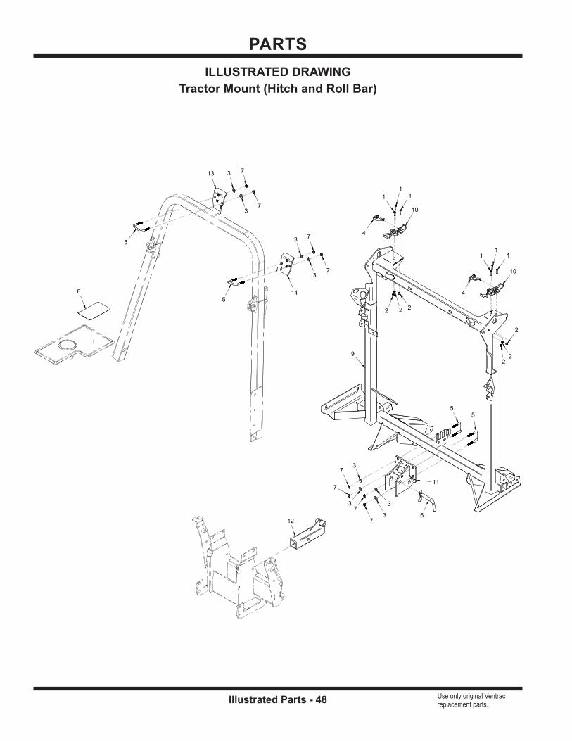
PARTS
Illustrated Parts - 48 Use only original Ventrac replacement parts.
8 4
4
6
5
5
5
5
10
10
11
12
9
13
14
3
3
3
3
3
3
3
3
7
7
7
7
7
7
7
7
2
2
22
22
1
1
11
1 1
ILLUSTRATED DRAWINGTractor Mount (Hitch and Roll Bar)

PARTS
Illustrated Parts - 49 Use only original Ventrac replacement parts.
REF. PART NO. DESCRIPTION QTY.1 . . . . . . . . . 99.K0102 . . . . . . . . . . . . . . . . . . .MACHINE SCREW, #12-24 X 3/4 ZP . . . . . . . . . . . . . . . . . . . . . . . . . . . . . . . . . . . . . . . . . . 6 2 . . . . . . . . . 99.E0089 . . . . . . . . . . . . . . . . . . .LOCKNUT, NYLON 12-24 ZP . . . . . . . . . . . . . . . . . . . . . . . . . . . . . . . . . . . . . . . . . . . . . . . . 6 3 . . . . . . . . . 95.06 . . . . . . . . . . . . . . . . . . . . . .WASHER, FLAT 3/8 SAE . . . . . . . . . . . . . . . . . . . . . . . . . . . . . . . . . . . . . . . . . . . . . . . . . . . 8 4 . . . . . . . . . 03.0009 . . . . . . . . . . . . . . . . . . . .PIN, SAFETY SNAP 1/4 X 1-3/8 . . . . . . . . . . . . . . . . . . . . . . . . . . . . . . . . . . . . . . . . . . . . . . 2 5 . . . . . . . . . 11.0053 . . . . . . . . . . . . . . . . . . . .U-BOLT, 3/8-16 2-1/16” ID SQ BEND . . . . . . . . . . . . . . . . . . . . . . . . . . . . . . . . . . . . . . . . . . 4 6 . . . . . . . . . 03.0014 . . . . . . . . . . . . . . . . . . . .PIN, HITCH 5/8” X 3” USABLE . . . . . . . . . . . . . . . . . . . . . . . . . . . . . . . . . . . . . . . . . . . . . . . 1
7 . . . . . . . . . 99.A06C . . . . . . . . . . . . . . . . . . .LOCKNUT, CENTER 3/8-16 . . . . . . . . . . . . . . . . . . . . . . . . . . . . . . . . . . . . . . . . . . . . . . . . . 8 8 . . . . . . . . . 00.0268 . . . . . . . . . . . . . . . . . . . .DECAL, COLLECTION SYSTEM RV600 . . . . . . . . . . . . . . . . . . . . . . . . . . . . . . . . . . . . . . 1 9 . . . . . . . . . 62.1396 . . . . . . . . . . . . . . . . . . . .FRAME, MAIN RV602 . . . . . . . . . . . . . . . . . . . . . . . . . . . . . . . . . . . . . . . . . . . . . . . . . . . . . . 1 10 . . . . . . . . 47.0273 . . . . . . . . . . . . . . . . . . . .LATCH, OVER CENTER ADJUSTABLE . . . . . . . . . . . . . . . . . . . . . . . . . . . . . . . . . . . . . . . 2 11 . . . . . . . . . 62.1316 . . . . . . . . . . . . . . . . . . . .HITCH, COLLECTION BASIC . . . . . . . . . . . . . . . . . . . . . . . . . . . . . . . . . . . . . . . . . . . . . . . 1 12 . . . . . . . . 62.1317 . . . . . . . . . . . . . . . . . . . .HITCH, TRACTOR RV BASIC . . . . . . . . . . . . . . . . . . . . . . . . . . . . . . . . . . . . . . . . . . . . . . . 1
13 . . . . . . . . 64.1747 . . . . . . . . . . . . . . . . . . . .MOUNT, ROLLBAR RIGHT . . . . . . . . . . . . . . . . . . . . . . . . . . . . . . . . . . . . . . . . . . . . . . . . . 1 14 . . . . . . . . 64.1748 . . . . . . . . . . . . . . . . . . . .MOUNT, ROLLBAR LEFT . . . . . . . . . . . . . . . . . . . . . . . . . . . . . . . . . . . . . . . . . . . . . . . . . . 1
Tractor Mount (Hitch and Roll Bar)
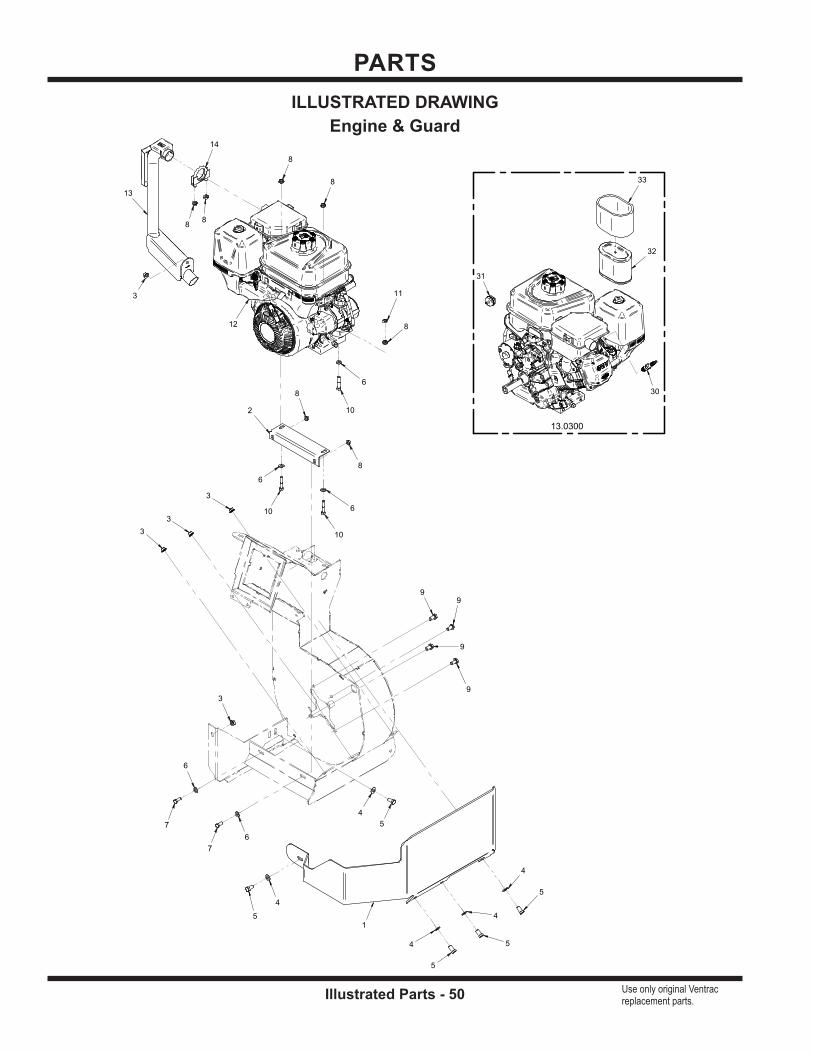
PARTS
Illustrated Parts - 50 Use only original Ventrac replacement parts.
14
13
12
1
2
7
7
10
10
10
5
5
5
5
5
11
6
6
6
6
6
4
4
4
4
4
8
8
8
8
8
8
8
3
3
3
3
3
99
9
9
13.0300
31
30
32
33
ILLUSTRATED DRAWINGEngine & Guard

PARTS
Illustrated Parts - 51 Use only original Ventrac replacement parts.
REF. PART NO. DESCRIPTION QTY.1 . . . . . . . . . 62.1410 . . . . . . . . . . . . . . . . . . . .BUMPER, ENGINE/FAN GUARD . . . . . . . . . . . . . . . . . . . . . . . . . . . . . . . . . . . . . . . . . . . . 1 2 . . . . . . . . . 64.1450 . . . . . . . . . . . . . . . . . . . .BRACKET, ENGINE MOUNT . . . . . . . . . . . . . . . . . . . . . . . . . . . . . . . . . . . . . . . . . . . . . . . . 1 3 . . . . . . . . . 99.SF06 . . . . . . . . . . . . . . . . . . .NUT, SF 3/8-16 USS . . . . . . . . . . . . . . . . . . . . . . . . . . . . . . . . . . . . . . . . . . . . . . . . . . . . . . . 5 4 . . . . . . . . . 95.06 . . . . . . . . . . . . . . . . . . . . . .WASHER, FLAT 3/8 SAE . . . . . . . . . . . . . . . . . . . . . . . . . . . . . . . . . . . . . . . . . . . . . . . . . . . 5 5 . . . . . . . . . 90.0606 . . . . . . . . . . . . . . . . . . . .BOLT, HEX 3/8-16 UNC X 3/4 . . . . . . . . . . . . . . . . . . . . . . . . . . . . . . . . . . . . . . . . . . . . . . . . 5 6 . . . . . . . . . 95.05 . . . . . . . . . . . . . . . . . . . . . .WASHER, FLAT 5/16 SAE . . . . . . . . . . . . . . . . . . . . . . . . . . . . . . . . . . . . . . . . . . . . . . . . . . 5
7 . . . . . . . . . 90.0506 . . . . . . . . . . . . . . . . . . . .BOLT, HEX 5/16-18 UNC X 3/4” . . . . . . . . . . . . . . . . . . . . . . . . . . . . . . . . . . . . . . . . . . . . . . 2 8 . . . . . . . . . 99.SF05 . . . . . . . . . . . . . . . . . . .NUT, SF 5/16-18 USS . . . . . . . . . . . . . . . . . . . . . . . . . . . . . . . . . . . . . . . . . . . . . . . . . . . . . . 7 9 . . . . . . . . . 99.SF0606 . . . . . . . . . . . . . . . . .BOLT, SF 3/8-16 UNC X 3/4 . . . . . . . . . . . . . . . . . . . . . . . . . . . . . . . . . . . . . . . . . . . . . . . . . 4 10 . . . . . . . . 90.0514 . . . . . . . . . . . . . . . . . . . .BOLT, HEX 5/16-18 UNC X 1-3/4” . . . . . . . . . . . . . . . . . . . . . . . . . . . . . . . . . . . . . . . . . . . . 3 11 . . . . . . . . . 92.05 . . . . . . . . . . . . . . . . . . . . . .NUT, HEX 5/16-18 UNC . . . . . . . . . . . . . . . . . . . . . . . . . . . . . . . . . . . . . . . . . . . . . . . . . . . . 1 12 . . . . . . . . 13.0300 . . . . . . . . . . . . . . . . . . . .ENGINE, B&S VANG 10HP GAS AC . . . . . . . . . . . . . . . . . . . . . . . . . . . . . . . . . . . . . . . . . . 1
13 . . . . . . . . 13.0234 . . . . . . . . . . . . . . . . . . . .TUBE, EXHAUST FOR 13.0233 . . . . . . . . . . . . . . . . . . . . . . . . . . . . . . . . . . . . . . . . . . . . . . 1 14 . . . . . . . . 11.0039 . . . . . . . . . . . . . . . . . . . .CLAMP, EXH. 5/16 X 1 1/2 ASM. . . . . . . . . . . . . . . . . . . . . . . . . . . . . . . . . . . . . . . . . . . . . . 1 30 . . . . . . . . 13.491055S . . . . . . . . . . . . . . . . .PLUG, SPARK . . . . . . . . . . . . . . . . . . . . . . . . . . . . . . . . . . . . . . . . . . . . . . . . . . . . . . . . . . . . 1 31 . . . . . . . . 13.394358S . . . . . . . . . . . . . . . . .FILTER, FUEL . . . . . . . . . . . . . . . . . . . . . . . . . . . . . . . . . . . . . . . . . . . . . . . . . . . . . . . . . . . . 1 32 . . . . . . . . 13.797032 . . . . . . . . . . . . . . . . . .FILTER, AIR . . . . . . . . . . . . . . . . . . . . . . . . . . . . . . . . . . . . . . . . . . . . . . . . . . . . . . . . . . . . . . 1 33 . . . . . . . . 13.798795 . . . . . . . . . . . . . . . . . .FILTER, AIR PRE CLEANER . . . . . . . . . . . . . . . . . . . . . . . . . . . . . . . . . . . . . . . . . . . . . . . . 1
Engine & Guard
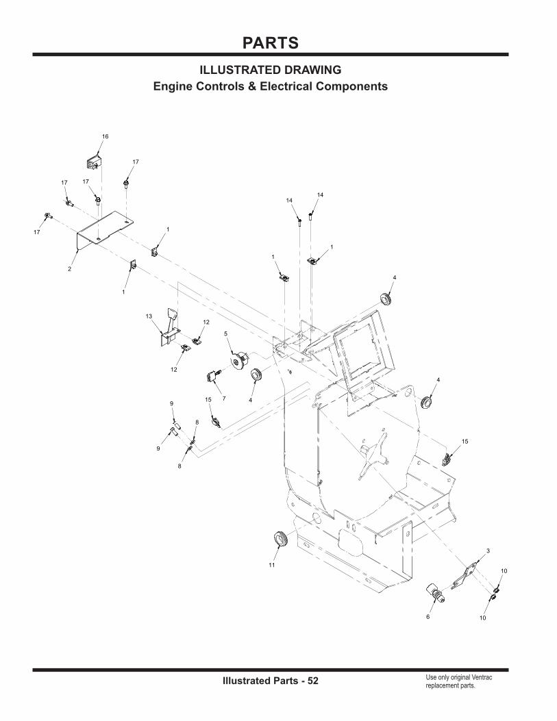
PARTS
Illustrated Parts - 52 Use only original Ventrac replacement parts.
4
4
4
11
5
715
15
6
16
13
2
3
9
9
8
8
1
1
1
1
12
12
1414
17
17
17
17
10
10
ILLUSTRATED DRAWINGEngine Controls & Electrical Components

PARTS
Illustrated Parts - 53 Use only original Ventrac replacement parts.
REF. PART NO. DESCRIPTION QTY.1 . . . . . . . . . 99.E0046 . . . . . . . . . . . . . . . . . . .NUT, “U” 1/4-20 EXTRUDED . . . . . . . . . . . . . . . . . . . . . . . . . . . . . . . . . . . . . . . . . . . . . . . . 4 2 . . . . . . . . . 60.1199 . . . . . . . . . . . . . . . . . . . .COVER, IGNITION SWITCH . . . . . . . . . . . . . . . . . . . . . . . . . . . . . . . . . . . . . . . . . . . . . . . . 1 3 . . . . . . . . . 64.1778 . . . . . . . . . . . . . . . . . . . .BRACKET, SHUTOFF SWITCH MOUNT . . . . . . . . . . . . . . . . . . . . . . . . . . . . . . . . . . . . . . 1 4 . . . . . . . . . 05.0045 . . . . . . . . . . . . . . . . . . . .GROMMET, 3/4ID, 1 3/8OD, 1/2THK . . . . . . . . . . . . . . . . . . . . . . . . . . . . . . . . . . . . . . . . . . 3 5 . . . . . . . . . 13.0078 . . . . . . . . . . . . . . . . . . . .SWITCH, IGNITION DELTA . . . . . . . . . . . . . . . . . . . . . . . . . . . . . . . . . . . . . . . . . . . . . . . . . 1 6 . . . . . . . . . 31.0048 . . . . . . . . . . . . . . . . . . . .SWITCH, ENGINE SHUTOFF - NC . . . . . . . . . . . . . . . . . . . . . . . . . . . . . . . . . . . . . . . . . . . 1
7 . . . . . . . . . 13.0080 . . . . . . . . . . . . . . . . . . . .KEY, IGNITION DELTA . . . . . . . . . . . . . . . . . . . . . . . . . . . . . . . . . . . . . . . . . . . . . . . . . . . . . 1 8 . . . . . . . . . 95.05 . . . . . . . . . . . . . . . . . . . . . .WASHER, FLAT 5/16 SAE . . . . . . . . . . . . . . . . . . . . . . . . . . . . . . . . . . . . . . . . . . . . . . . . . . 2 9 . . . . . . . . . 90.0506 . . . . . . . . . . . . . . . . . . . .BOLT, HEX 5/16-18 UNC X 3/4” . . . . . . . . . . . . . . . . . . . . . . . . . . . . . . . . . . . . . . . . . . . . . . 2 10 . . . . . . . . 99.SF05 . . . . . . . . . . . . . . . . . . .NUT, SF 5/16-18 USS . . . . . . . . . . . . . . . . . . . . . . . . . . . . . . . . . . . . . . . . . . . . . . . . . . . . . . 2 11 . . . . . . . . . 05.0060 . . . . . . . . . . . . . . . . . . . .GROMMET, 1-1/8 ID, 1-3/4 OD . . . . . . . . . . . . . . . . . . . . . . . . . . . . . . . . . . . . . . . . . . . . . . 1 12 . . . . . . . . 99.E0091 . . . . . . . . . . . . . . . . . . .NUT, “U” #10-24 EXTRUDED . . . . . . . . . . . . . . . . . . . . . . . . . . . . . . . . . . . . . . . . . . . . . . . . 2
13 . . . . . . . . 47.0179 . . . . . . . . . . . . . . . . . . . .CABLE, THROTTLE 40” 1-5/8 TRAV . . . . . . . . . . . . . . . . . . . . . . . . . . . . . . . . . . . . . . . . . . 1 14 . . . . . . . . 99.K0106 . . . . . . . . . . . . . . . . . . .MACHINE SCREW, #10-24 X 3/4 . . . . . . . . . . . . . . . . . . . . . . . . . . . . . . . . . . . . . . . . . . . . . 2 15 . . . . . . . . 30.0135 . . . . . . . . . . . . . . . . . . . .CLAMP, LOOM 3/8 ROSEBUD MOUNT . . . . . . . . . . . . . . . . . . . . . . . . . . . . . . . . . . . . . . . 2 16 . . . . . . . . 35.0138 . . . . . . . . . . . . . . . . . . . .GAUGE, HOUR METER 12V . . . . . . . . . . . . . . . . . . . . . . . . . . . . . . . . . . . . . . . . . . . . . . . . 1 17 . . . . . . . . 99.SF0405-1 . . . . . . . . . . . . . . . .BOLT, SMF 1/4-20 X 5/8 . . . . . . . . . . . . . . . . . . . . . . . . . . . . . . . . . . . . . . . . . . . . . . . . . . . . 4
Engine Controls & Electrical Components

PARTS
Illustrated Parts - 54 Use only original Ventrac replacement parts.
55
6
7
3
2
2
4 4
1
1
ILLUSTRATED DRAWINGBattery Cable Connector
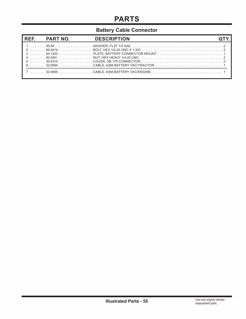
PARTS
Illustrated Parts - 55 Use only original Ventrac replacement parts.
REF. PART NO. DESCRIPTION QTY.1 . . . . . . . . . 95.04 . . . . . . . . . . . . . . . . . . . . . .WASHER, FLAT 1/4 SAE . . . . . . . . . . . . . . . . . . . . . . . . . . . . . . . . . . . . . . . . . . . . . . . . . . . 2 2 . . . . . . . . . 90.0414 . . . . . . . . . . . . . . . . . . . .BOLT, HEX 1/4-20 UNC X 1-3/4” . . . . . . . . . . . . . . . . . . . . . . . . . . . . . . . . . . . . . . . . . . . . . 2 3 . . . . . . . . . 64.1433 . . . . . . . . . . . . . . . . . . . .PLATE, BATTERY CONNECTOR MOUNT . . . . . . . . . . . . . . . . . . . . . . . . . . . . . . . . . . . . . 1 4 . . . . . . . . . 92.04H . . . . . . . . . . . . . . . . . . . .NUT, HEX HEAVY 1/4-20 UNC . . . . . . . . . . . . . . . . . . . . . . . . . . . . . . . . . . . . . . . . . . . . . . . 2 5 . . . . . . . . . 30.0315 . . . . . . . . . . . . . . . . . . . .COVER, SB 175 CONNECTOR . . . . . . . . . . . . . . . . . . . . . . . . . . . . . . . . . . . . . . . . . . . . . . 2 6 . . . . . . . . . 32.0094 . . . . . . . . . . . . . . . . . . . .CABLE, ASM BATTERY VAC/TRACTOR . . . . . . . . . . . . . . . . . . . . . . . . . . . . . . . . . . . . . . 1
7 . . . . . . . . . 32.0095 . . . . . . . . . . . . . . . . . . . .CABLE, ASM BATTERY VAC/ENGINE . . . . . . . . . . . . . . . . . . . . . . . . . . . . . . . . . . . . . . . . 1
Battery Cable Connector

PARTS
Illustrated Parts - 56 Use only original Ventrac replacement parts.
80.0373
1113
14
12
1
21
10
22
23
5
5
9
7
7
7
7
4
4
8
15
17
2
2
2
16
16
18
6
6
6
6
6
6
20
20
20
20
20
20
20
20
20
3
3
19
35
36
38
37
37
15
ILLUSTRATED DRAWINGFan Housing, Fan, & Upper Chute

Illustrated Parts - 57 Use only original Ventrac replacement parts.
REF. PART NO. DESCRIPTION QTY.1 . . . . . . . . . 03.0016 . . . . . . . . . . . . . . . . . . . .PIN, LIFT ARM 5/8 X 3-7/8 . . . . . . . . . . . . . . . . . . . . . . . . . . . . . . . . . . . . . . . . . . . . . . . . . . 1 2 . . . . . . . . . 99.E0046 . . . . . . . . . . . . . . . . . . .NUT, “U” 1/4-20 EXTRUDED . . . . . . . . . . . . . . . . . . . . . . . . . . . . . . . . . . . . . . . . . . . . . . . . 3 3 . . . . . . . . . 99.SF06 . . . . . . . . . . . . . . . . . . .NUT, SF 3/8-16 USS . . . . . . . . . . . . . . . . . . . . . . . . . . . . . . . . . . . . . . . . . . . . . . . . . . . . . . . 2 4 . . . . . . . . . 95.06 . . . . . . . . . . . . . . . . . . . . . .WASHER, FLAT 3/8 SAE . . . . . . . . . . . . . . . . . . . . . . . . . . . . . . . . . . . . . . . . . . . . . . . . . . . 2 5 . . . . . . . . . 90.0608 . . . . . . . . . . . . . . . . . . . .BOLT, HEX 3/8-16 UNC X 1 . . . . . . . . . . . . . . . . . . . . . . . . . . . . . . . . . . . . . . . . . . . . . . . . . 2 6 . . . . . . . . . 99.SF04 . . . . . . . . . . . . . . . . . . .NUT, SF 1/4-20 USS . . . . . . . . . . . . . . . . . . . . . . . . . . . . . . . . . . . . . . . . . . . . . . . . . . . . . . . 6
7 . . . . . . . . . 94.10 . . . . . . . . . . . . . . . . . . . . . .WASHER, FLAT 5/8 USS . . . . . . . . . . . . . . . . . . . . . . . . . . . . . . . . . . . . . . . . . . . . . . . . . . . 4 8 . . . . . . . . . 96.10 . . . . . . . . . . . . . . . . . . . . . .WASHER, LOCK 5/8 . . . . . . . . . . . . . . . . . . . . . . . . . . . . . . . . . . . . . . . . . . . . . . . . . . . . . . . 1 9 . . . . . . . . . 92.10 . . . . . . . . . . . . . . . . . . . . . .NUT, HEX 5/8-11UNC . . . . . . . . . . . . . . . . . . . . . . . . . . . . . . . . . . . . . . . . . . . . . . . . . . . . . . 1 10 . . . . . . . . 60.1183 . . . . . . . . . . . . . . . . . . . .SHIELD, ENGINE EXHAUST. . . . . . . . . . . . . . . . . . . . . . . . . . . . . . . . . . . . . . . . . . . . . . . . 1 11 . . . . . . . . . 00.0122 . . . . . . . . . . . . . . . . . . . .DECAL, THROWN OBJECT HAZARD . . . . . . . . . . . . . . . . . . . . . . . . . . . . . . . . . . . . . . . . 1 12 . . . . . . . . 00.0332 . . . . . . . . . . . . . . . . . . . .DECAL, GASOLINE ONLY . . . . . . . . . . . . . . . . . . . . . . . . . . . . . . . . . . . . . . . . . . . . . . . . . . 1
13 . . . . . . . . 00.0217 . . . . . . . . . . . . . . . . . . . .DECAL, WARNING READ OWNERS MAN . . . . . . . . . . . . . . . . . . . . . . . . . . . . . . . . . . . . 1 14 . . . . . . . . 00.0219 . . . . . . . . . . . . . . . . . . . .DECAL, WARNING DO NOT REACH . . . . . . . . . . . . . . . . . . . . . . . . . . . . . . . . . . . . . . . . . 1 15 . . . . . . . . 99.B0017 . . . . . . . . . . . . . . . . . . .WASHER, MACH 1” 18GA . . . . . . . . . . . . . . . . . . . . . . . . . . . . . . . . . . . . . . . . . . . . . . . . . . 2 16 . . . . . . . . 99.G0014 . . . . . . . . . . . . . . . . . .WASHER, 3/8 USS FW .165 THK . . . . . . . . . . . . . . . . . . . . . . . . . . . . . . . . . . . . . . . . . . . . 2 17 . . . . . . . . 99.B0047 . . . . . . . . . . . . . . . . . . .WASHER, FLAT 3/8 SAE GRADE 8 . . . . . . . . . . . . . . . . . . . . . . . . . . . . . . . . . . . . . . . . . . 1 18 . . . . . . . . 99.K0104 . . . . . . . . . . . . . . . . . . .BOLT, 3/8-24 X 1 GRD 8 . . . . . . . . . . . . . . . . . . . . . . . . . . . . . . . . . . . . . . . . . . . . . . . . . . . . 1
19 . . . . . . . . 06.0043-22.5IN . . . . . . . . . . . . . .TRIM, 7/16” BULB SEAL TOP 1/16T X 22-1/2” . . . . . . . . . . . . . . . . . . . . . . . . . . . . . . . . . . 1 20 . . . . . . . . 99.SF0405-1 . . . . . . . . . . . . . . . .BOLT, SMF 1/4-20 X 5/8 . . . . . . . . . . . . . . . . . . . . . . . . . . . . . . . . . . . . . . . . . . . . . . . . . . . . 9 21 . . . . . . . . 60.1182 . . . . . . . . . . . . . . . . . . . .DUCT, COLLECTION BIN . . . . . . . . . . . . . . . . . . . . . . . . . . . . . . . . . . . . . . . . . . . . . . . . . . 1 22 . . . . . . . . 62.1395 . . . . . . . . . . . . . . . . . . . .HOUSING, COLLECTION FAN . . . . . . . . . . . . . . . . . . . . . . . . . . . . . . . . . . . . . . . . . . . . . . 1 23 . . . . . . . . 80.0373 . . . . . . . . . . . . . . . . . . . .FAN, COLLECTION SYSTEM ASM . . . . . . . . . . . . . . . . . . . . . . . . . . . . . . . . . . . . . . . . . . 1 35 . . . . . . . . 80.0373-1 . . . . . . . . . . . . . . . . . .FAN, COLLECTION SYSTEM . . . . . . . . . . . . . . . . . . . . . . . . . . . . . . . . . . . . . . . . . . . . . . . 1
36 . . . . . . . . 80.0373-2 . . . . . . . . . . . . . . . . . .BUSHING, 1” TAPER HUB . . . . . . . . . . . . . . . . . . . . . . . . . . . . . . . . . . . . . . . . . . . . . . . . . . 1 37 . . . . . . . . 90.0408 . . . . . . . . . . . . . . . . . . . .BOLT, HEX 1/4-20 UNC X 1”. . . . . . . . . . . . . . . . . . . . . . . . . . . . . . . . . . . . . . . . . . . . . . . . . 2 38 . . . . . . . . 80.0373-3 . . . . . . . . . . . . . . . . . .WASHER, COLLECTION FAN . . . . . . . . . . . . . . . . . . . . . . . . . . . . . . . . . . . . . . . . . . . . . . . 1
Fan Housing, Fan, & Upper Chute
PARTS
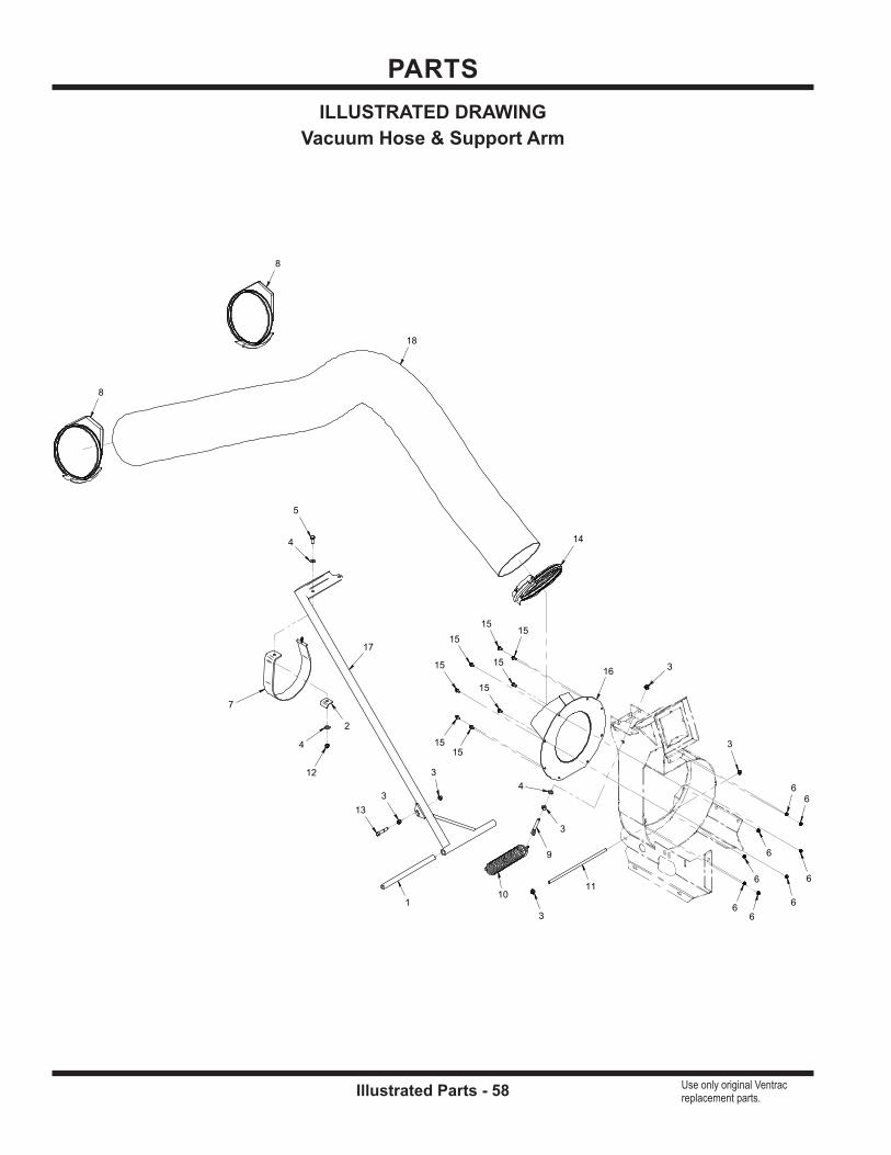
PARTS
Illustrated Parts - 58 Use only original Ventrac replacement parts.
8
8
14
10
17
11
7
18
16
1
2
5
13
4
4
412
9
6
66
6
6
66
6
15
15
15
15
15
15
15
15
3
3
3
3
3
3
ILLUSTRATED DRAWINGVacuum Hose & Support Arm
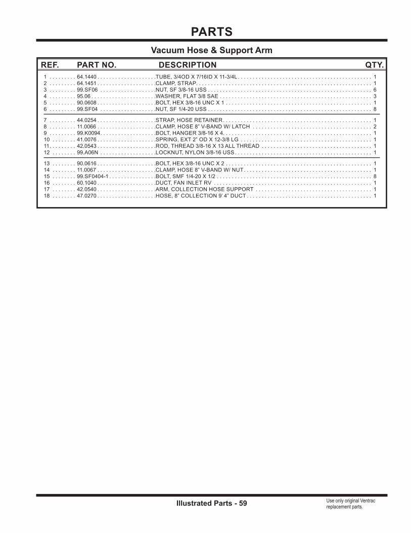
PARTS
Illustrated Parts - 59 Use only original Ventrac replacement parts.
REF. PART NO. DESCRIPTION QTY.1 . . . . . . . . . 64.1440 . . . . . . . . . . . . . . . . . . . .TUBE, 3/4OD X 7/16ID X 11-3/4L . . . . . . . . . . . . . . . . . . . . . . . . . . . . . . . . . . . . . . . . . . . . . 1 2 . . . . . . . . . 64.1451 . . . . . . . . . . . . . . . . . . . .CLAMP, STRAP. . . . . . . . . . . . . . . . . . . . . . . . . . . . . . . . . . . . . . . . . . . . . . . . . . . . . . . . . . . 1 3 . . . . . . . . . 99.SF06 . . . . . . . . . . . . . . . . . . .NUT, SF 3/8-16 USS . . . . . . . . . . . . . . . . . . . . . . . . . . . . . . . . . . . . . . . . . . . . . . . . . . . . . . . 6 4 . . . . . . . . . 95.06 . . . . . . . . . . . . . . . . . . . . . .WASHER, FLAT 3/8 SAE . . . . . . . . . . . . . . . . . . . . . . . . . . . . . . . . . . . . . . . . . . . . . . . . . . . 3 5 . . . . . . . . . 90.0608 . . . . . . . . . . . . . . . . . . . .BOLT, HEX 3/8-16 UNC X 1 . . . . . . . . . . . . . . . . . . . . . . . . . . . . . . . . . . . . . . . . . . . . . . . . . 1 6 . . . . . . . . . 99.SF04 . . . . . . . . . . . . . . . . . . .NUT, SF 1/4-20 USS . . . . . . . . . . . . . . . . . . . . . . . . . . . . . . . . . . . . . . . . . . . . . . . . . . . . . . . 8
7 . . . . . . . . . 44.0254 . . . . . . . . . . . . . . . . . . . .STRAP, HOSE RETAINER . . . . . . . . . . . . . . . . . . . . . . . . . . . . . . . . . . . . . . . . . . . . . . . . . . 1 8 . . . . . . . . . 11.0066 . . . . . . . . . . . . . . . . . . . .CLAMP, HOSE 8” V-BAND W/ LATCH . . . . . . . . . . . . . . . . . . . . . . . . . . . . . . . . . . . . . . . . 2 9 . . . . . . . . . 99.K0094 . . . . . . . . . . . . . . . . . . .BOLT, HANGER 3/8-16 X 4. . . . . . . . . . . . . . . . . . . . . . . . . . . . . . . . . . . . . . . . . . . . . . . . . . 1 10 . . . . . . . . 41.0076 . . . . . . . . . . . . . . . . . . . .SPRING, EXT 2” OD X 12-3/8 LG . . . . . . . . . . . . . . . . . . . . . . . . . . . . . . . . . . . . . . . . . . . . 1 11 . . . . . . . . . 42.0543 . . . . . . . . . . . . . . . . . . . .ROD, THREAD 3/8-16 X 13 ALL THREAD . . . . . . . . . . . . . . . . . . . . . . . . . . . . . . . . . . . . . 1 12 . . . . . . . . 99.A06N . . . . . . . . . . . . . . . . . . .LOCKNUT, NYLON 3/8-16 USS . . . . . . . . . . . . . . . . . . . . . . . . . . . . . . . . . . . . . . . . . . . . . . 1
13 . . . . . . . . 90.0616 . . . . . . . . . . . . . . . . . . . .BOLT, HEX 3/8-16 UNC X 2 . . . . . . . . . . . . . . . . . . . . . . . . . . . . . . . . . . . . . . . . . . . . . . . . . 1 14 . . . . . . . . 11.0067 . . . . . . . . . . . . . . . . . . . .CLAMP, HOSE 8” V-BAND W/ NUT . . . . . . . . . . . . . . . . . . . . . . . . . . . . . . . . . . . . . . . . . . . 1 15 . . . . . . . . 99.SF0404-1 . . . . . . . . . . . . . . . .BOLT, SMF 1/4-20 X 1/2 . . . . . . . . . . . . . . . . . . . . . . . . . . . . . . . . . . . . . . . . . . . . . . . . . . . . 8 16 . . . . . . . . 60.1040 . . . . . . . . . . . . . . . . . . . .DUCT, FAN INLET RV . . . . . . . . . . . . . . . . . . . . . . . . . . . . . . . . . . . . . . . . . . . . . . . . . . . . . 1 17 . . . . . . . . 42.0540 . . . . . . . . . . . . . . . . . . . .ARM, COLLECTION HOSE SUPPORT . . . . . . . . . . . . . . . . . . . . . . . . . . . . . . . . . . . . . . . 1 18 . . . . . . . . 47.0270 . . . . . . . . . . . . . . . . . . . .HOSE, 8” COLLECTION 9’ 4” DUCT . . . . . . . . . . . . . . . . . . . . . . . . . . . . . . . . . . . . . . . . . . 1
Vacuum Hose & Support Arm

PARTS
Illustrated Parts - 60 Use only original Ventrac replacement parts.
16
16
13
13
7
7
7
715
11
12
12
1
5
5
10
1010 10
1010
10
10 1010
101010
10
10
10
4
4
4
4
9
9
9
9
9 9
99
9
9
9
9
99
9
9
2
2
2
2
14
14
6
6
8
88
88
8
88
8
8 88
8
8
8
8
3
3
3
3
ILLUSTRATED DRAWINGStorage Stands with Casters

PARTS
Illustrated Parts - 61 Use only original Ventrac replacement parts.
REF. PART NO. DESCRIPTION QTY.1 . . . . . . . . . 64.1460 . . . . . . . . . . . . . . . . . . . .FRAME, MAIN EXTENSION - RV . . . . . . . . . . . . . . . . . . . . . . . . . . . . . . . . . . . . . . . . . . . . 1 2 . . . . . . . . . 95.06 . . . . . . . . . . . . . . . . . . . . . .WASHER, FLAT 3/8 SAE . . . . . . . . . . . . . . . . . . . . . . . . . . . . . . . . . . . . . . . . . . . . . . . . . . . 4 3 . . . . . . . . . 99.SF06 . . . . . . . . . . . . . . . . . . .NUT, SF 3/8-16 USS . . . . . . . . . . . . . . . . . . . . . . . . . . . . . . . . . . . . . . . . . . . . . . . . . . . . . . . 4 4 . . . . . . . . . 90.0608 . . . . . . . . . . . . . . . . . . . .BOLT, HEX 3/8-16 UNC X 1 . . . . . . . . . . . . . . . . . . . . . . . . . . . . . . . . . . . . . . . . . . . . . . . . . 4 5 . . . . . . . . . 90.0404 . . . . . . . . . . . . . . . . . . . .BOLT, HEX 1/4-20 UNC X 1/2” . . . . . . . . . . . . . . . . . . . . . . . . . . . . . . . . . . . . . . . . . . . . . . . 2 6 . . . . . . . . . 99.SF04 . . . . . . . . . . . . . . . . . . .NUT, SF 1/4-20 USS . . . . . . . . . . . . . . . . . . . . . . . . . . . . . . . . . . . . . . . . . . . . . . . . . . . . . . . 2
7 . . . . . . . . . 53.0136 . . . . . . . . . . . . . . . . . . . .WHEEL, CASTER 3-1/2 DIA X 1-1/4 . . . . . . . . . . . . . . . . . . . . . . . . . . . . . . . . . . . . . . . . . . 4 8 . . . . . . . . . 99.SF05 . . . . . . . . . . . . . . . . . . .NUT, SF 5/16-18 USS . . . . . . . . . . . . . . . . . . . . . . . . . . . . . . . . . . . . . . . . . . . . . . . . . . . . . 16 9 . . . . . . . . . 95.05 . . . . . . . . . . . . . . . . . . . . . .WASHER, FLAT 5/16 SAE . . . . . . . . . . . . . . . . . . . . . . . . . . . . . . . . . . . . . . . . . . . . . . . . . 16 10 . . . . . . . . 90.0506 . . . . . . . . . . . . . . . . . . . .BOLT, HEX 5/16-18 UNC X 3/4” . . . . . . . . . . . . . . . . . . . . . . . . . . . . . . . . . . . . . . . . . . . . . 16 11 . . . . . . . . . 62.1310 . . . . . . . . . . . . . . . . . . . .STAND, RV STORAGE LEFT . . . . . . . . . . . . . . . . . . . . . . . . . . . . . . . . . . . . . . . . . . . . . . . 1 12 . . . . . . . . 62.1311 . . . . . . . . . . . . . . . . . . . .STAND, STORAGE LEG . . . . . . . . . . . . . . . . . . . . . . . . . . . . . . . . . . . . . . . . . . . . . . . . . . . 2
13 . . . . . . . . 42.0539 . . . . . . . . . . . . . . . . . . . .ADJUSTER, RV STORAGE STAND . . . . . . . . . . . . . . . . . . . . . . . . . . . . . . . . . . . . . . . . . . 2 14 . . . . . . . . 99.E0093 . . . . . . . . . . . . . . . . . . .NUT, WING 1/2-13 USS . . . . . . . . . . . . . . . . . . . . . . . . . . . . . . . . . . . . . . . . . . . . . . . . . . . . 2 15 . . . . . . . . 62.1309 . . . . . . . . . . . . . . . . . . . .STAND, RV STORAGE RIGHT . . . . . . . . . . . . . . . . . . . . . . . . . . . . . . . . . . . . . . . . . . . . . . 1 16 . . . . . . . . 03.0015 . . . . . . . . . . . . . . . . . . . .PIN, SAFETY SNAP 3/8 X 3” . . . . . . . . . . . . . . . . . . . . . . . . . . . . . . . . . . . . . . . . . . . . . . . . 2
Storage Stands with Casters
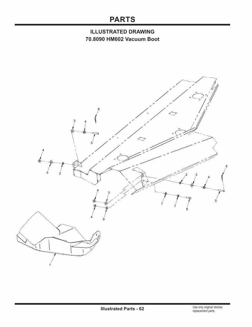
PARTS
Illustrated Parts - 62 Use only original Ventrac replacement parts.
4
4
4
6
3
3
9
77
5
23
4
6
24
5
8
3
1
ILLUSTRATED DRAWING70.8090 HM602 Vacuum Boot

PARTS
Illustrated Parts - 63 Use only original Ventrac replacement parts.
REF. PART NO. DESCRIPTION QTY.1 . . . . . . . . . 62.1305 . . . . . . . . . . . . . . . . . . . .BOOT, COLLECTION - HM602 . . . . . . . . . . . . . . . . . . . . . . . . . . . . . . . . . . . . . . . . . . . . . . 1 2 . . . . . . . . . 05.0119 . . . . . . . . . . . . . . . . . . . .WASHER, NYLON . . . . . . . . . . . . . . . . . . . . . . . . . . . . . . . . . . . . . . . . . . . . . . . . . . . . . . . . 2 3 . . . . . . . . . 94.06 . . . . . . . . . . . . . . . . . . . . . .WASHER, FLAT 3/8 USS . . . . . . . . . . . . . . . . . . . . . . . . . . . . . . . . . . . . . . . . . . . . . . . . . . . 4 4 . . . . . . . . . 99.SF06 . . . . . . . . . . . . . . . . . . .NUT, SRF 3/8-16 USS . . . . . . . . . . . . . . . . . . . . . . . . . . . . . . . . . . . . . . . . . . . . . . . . . . . . . . 5 5 . . . . . . . . . 99.F0042 . . . . . . . . . . . . . . . . . . .PIN, LIFT ARM 3/8-16 X 1-7/8 . . . . . . . . . . . . . . . . . . . . . . . . . . . . . . . . . . . . . . . . . . . . . . . 2 6 . . . . . . . . . 02.HP0313 . . . . . . . . . . . . . . . . .HAIRPIN, 3/32 X 1-5/8 . . . . . . . . . . . . . . . . . . . . . . . . . . . . . . . . . . . . . . . . . . . . . . . . . . . . . 2
7 . . . . . . . . . 64.0602 . . . . . . . . . . . . . . . . . . . .BUSHING, 3/8 X 5/8 X .265 . . . . . . . . . . . . . . . . . . . . . . . . . . . . . . . . . . . . . . . . . . . . . . . . . 2 8 . . . . . . . . . 90.0610 . . . . . . . . . . . . . . . . . . . .BOLT, 3/8-16 USS X 1-1/4 . . . . . . . . . . . . . . . . . . . . . . . . . . . . . . . . . . . . . . . . . . . . . . . . . . . 1 9 . . . . . . . . . 95.06 . . . . . . . . . . . . . . . . . . . . . .WASHER, FLAT 3/8 SAE . . . . . . . . . . . . . . . . . . . . . . . . . . . . . . . . . . . . . . . . . . . . . . . . . . . 1
70.8090 HM602 Vacuum Boot

PARTS
Illustrated Parts - 64 Use only original Ventrac replacement parts.
ILLUSTRATED DRAWING70.8091 HM/HP722 Vacuum Boot
3
3
5
2
2
8
66
4
12
3
3 2
7
13
4
5
9

PARTS
Illustrated Parts - 65 Use only original Ventrac replacement parts.
REF. PART NO. DESCRIPTION QTY.1 . . . . . . . . . 05.0119 . . . . . . . . . . . . . . . . . . . .WASHER, NYLON . . . . . . . . . . . . . . . . . . . . . . . . . . . . . . . . . . . . . . . . . . . . . . . . . . . . . . . . 2 2 . . . . . . . . . 94.06 . . . . . . . . . . . . . . . . . . . . . .WASHER, FLAT 3/8 USS . . . . . . . . . . . . . . . . . . . . . . . . . . . . . . . . . . . . . . . . . . . . . . . . . . . 4 3 . . . . . . . . . 99.SF06 . . . . . . . . . . . . . . . . . . .NUT, SRF 3/8-16 USS . . . . . . . . . . . . . . . . . . . . . . . . . . . . . . . . . . . . . . . . . . . . . . . . . . . . . . 5 4 . . . . . . . . . 99.F0042 . . . . . . . . . . . . . . . . . . .PIN, LIFT ARM 3/8-16 X 1-7/8 . . . . . . . . . . . . . . . . . . . . . . . . . . . . . . . . . . . . . . . . . . . . . . . 2 5 . . . . . . . . . 02.HP0313 . . . . . . . . . . . . . . . . .HAIRPIN, 3/32 X 1-5/8 . . . . . . . . . . . . . . . . . . . . . . . . . . . . . . . . . . . . . . . . . . . . . . . . . . . . . 2 6 . . . . . . . . . 64.0602 . . . . . . . . . . . . . . . . . . . .BUSHING, 3/8 X 5/8 X .265 . . . . . . . . . . . . . . . . . . . . . . . . . . . . . . . . . . . . . . . . . . . . . . . . . 2
7 . . . . . . . . . 90.0610 . . . . . . . . . . . . . . . . . . . .BOLT, 3/8-16 USS X 1-1/4 . . . . . . . . . . . . . . . . . . . . . . . . . . . . . . . . . . . . . . . . . . . . . . . . . . . 1 8 . . . . . . . . . 95.06 . . . . . . . . . . . . . . . . . . . . . .WASHER, FLAT 3/8 SAE . . . . . . . . . . . . . . . . . . . . . . . . . . . . . . . . . . . . . . . . . . . . . . . . . . . 1 9 . . . . . . . . . 62.1315 . . . . . . . . . . . . . . . . . . . .BOOT, COLLECTION - HM/HP722 . . . . . . . . . . . . . . . . . . . . . . . . . . . . . . . . . . . . . . . . . . . 1
70.8091 HM/HP722 Vacuum Boot
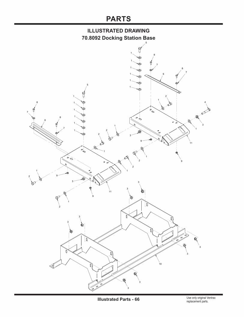
PARTS
Illustrated Parts - 66 Use only original Ventrac replacement parts.
6
6
10
11
11
8
8
8
8
2
2
2
2
2
2
2
5
5
4
7
7
7
7
1
1
1
1
1
1
1
1
1
1
1
1
1
1
1 1
1
1
1
1
9
9
9
9
3
3
3
3
3
3
3
3
3
3
3
ILLUSTRATED DRAWING70.8092 Docking Station Base
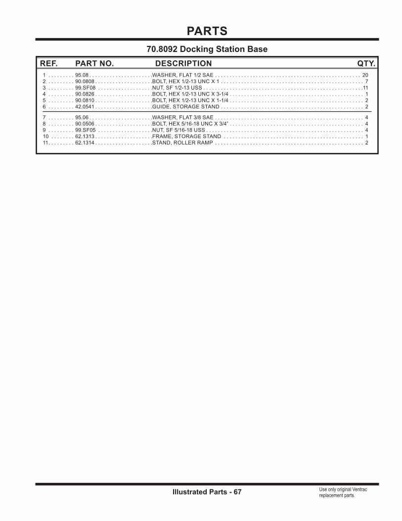
PARTS
Illustrated Parts - 67 Use only original Ventrac replacement parts.
REF. PART NO. DESCRIPTION QTY.1 . . . . . . . . . 95.08 . . . . . . . . . . . . . . . . . . . . . .WASHER, FLAT 1/2 SAE . . . . . . . . . . . . . . . . . . . . . . . . . . . . . . . . . . . . . . . . . . . . . . . . . . 20 2 . . . . . . . . . 90.0808 . . . . . . . . . . . . . . . . . . . .BOLT, HEX 1/2-13 UNC X 1 . . . . . . . . . . . . . . . . . . . . . . . . . . . . . . . . . . . . . . . . . . . . . . . . . 7 3 . . . . . . . . . 99.SF08 . . . . . . . . . . . . . . . . . . .NUT, SF 1/2-13 USS . . . . . . . . . . . . . . . . . . . . . . . . . . . . . . . . . . . . . . . . . . . . . . . . . . . . . . .11 4 . . . . . . . . . 90.0826 . . . . . . . . . . . . . . . . . . . .BOLT, HEX 1/2-13 UNC X 3-1/4 . . . . . . . . . . . . . . . . . . . . . . . . . . . . . . . . . . . . . . . . . . . . . . 1 5 . . . . . . . . . 90.0810 . . . . . . . . . . . . . . . . . . . .BOLT, HEX 1/2-13 UNC X 1-1/4 . . . . . . . . . . . . . . . . . . . . . . . . . . . . . . . . . . . . . . . . . . . . . . 2 6 . . . . . . . . . 42.0541 . . . . . . . . . . . . . . . . . . . .GUIDE, STORAGE STAND . . . . . . . . . . . . . . . . . . . . . . . . . . . . . . . . . . . . . . . . . . . . . . . . . 2
7 . . . . . . . . . 95.06 . . . . . . . . . . . . . . . . . . . . . .WASHER, FLAT 3/8 SAE . . . . . . . . . . . . . . . . . . . . . . . . . . . . . . . . . . . . . . . . . . . . . . . . . . . 4 8 . . . . . . . . . 90.0506 . . . . . . . . . . . . . . . . . . . .BOLT, HEX 5/16-18 UNC X 3/4” . . . . . . . . . . . . . . . . . . . . . . . . . . . . . . . . . . . . . . . . . . . . . . 4 9 . . . . . . . . . 99.SF05 . . . . . . . . . . . . . . . . . . .NUT, SF 5/16-18 USS . . . . . . . . . . . . . . . . . . . . . . . . . . . . . . . . . . . . . . . . . . . . . . . . . . . . . . 4 10 . . . . . . . . 62.1313 . . . . . . . . . . . . . . . . . . . .FRAME, STORAGE STAND . . . . . . . . . . . . . . . . . . . . . . . . . . . . . . . . . . . . . . . . . . . . . . . . 1 11 . . . . . . . . . 62.1314 . . . . . . . . . . . . . . . . . . . .STAND, ROLLER RAMP . . . . . . . . . . . . . . . . . . . . . . . . . . . . . . . . . . . . . . . . . . . . . . . . . . . 2
70.8092 Docking Station Base
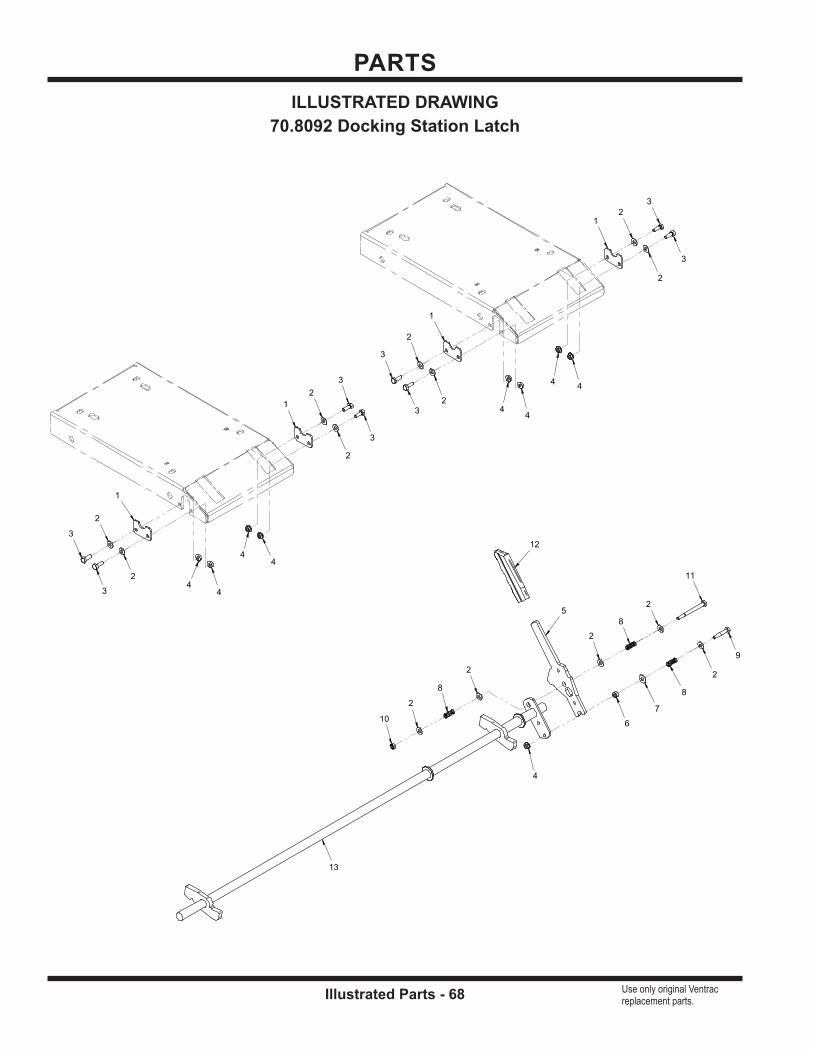
PARTS
Illustrated Parts - 68 Use only original Ventrac replacement parts.
5
8 8
8
12
13
1
1
1
1
3
3
3
3
3
3
3
3
9
11
6
7
2
2
2
2
2
2
22
2
2
2
2
2
10
4
4
4
4
44
4
4
4
ILLUSTRATED DRAWING70.8092 Docking Station Latch

PARTS
Illustrated Parts - 69 Use only original Ventrac replacement parts.
REF. PART NO. DESCRIPTION QTY.1 . . . . . . . . . 64.1439 . . . . . . . . . . . . . . . . . . . .RETAINER, STORAGE LATCH . . . . . . . . . . . . . . . . . . . . . . . . . . . . . . . . . . . . . . . . . . . . . . 4 2 . . . . . . . . . 95.04 . . . . . . . . . . . . . . . . . . . . . .WASHER, FLAT 1/4 SAE . . . . . . . . . . . . . . . . . . . . . . . . . . . . . . . . . . . . . . . . . . . . . . . . . . 13 3 . . . . . . . . . 90.0406 . . . . . . . . . . . . . . . . . . . .BOLT, HEX 1/4-20 UNC X 3/4” . . . . . . . . . . . . . . . . . . . . . . . . . . . . . . . . . . . . . . . . . . . . . . . 8 4 . . . . . . . . . 99.SF04 . . . . . . . . . . . . . . . . . . .NUT, SF 1/4-20 USS . . . . . . . . . . . . . . . . . . . . . . . . . . . . . . . . . . . . . . . . . . . . . . . . . . . . . . . 9 5 . . . . . . . . . 40.0358 . . . . . . . . . . . . . . . . . . . .HANDLE, STORAGE LATCH . . . . . . . . . . . . . . . . . . . . . . . . . . . . . . . . . . . . . . . . . . . . . . . . 1 6 . . . . . . . . . 92.04 . . . . . . . . . . . . . . . . . . . . . .NUT, HEX 1/4-20 UNC . . . . . . . . . . . . . . . . . . . . . . . . . . . . . . . . . . . . . . . . . . . . . . . . . . . . . 1
7 . . . . . . . . . 94.04 . . . . . . . . . . . . . . . . . . . . . .WASHER, FLAT 1/4 USS . . . . . . . . . . . . . . . . . . . . . . . . . . . . . . . . . . . . . . . . . . . . . . . . . . . 1 8 . . . . . . . . . 41.0094 . . . . . . . . . . . . . . . . . . . .SPRING, COMP 3/8 OD X 1” LG . . . . . . . . . . . . . . . . . . . . . . . . . . . . . . . . . . . . . . . . . . . . . 3 9 . . . . . . . . . 90.0412 . . . . . . . . . . . . . . . . . . . .BOLT, HEX 1/4-20 UNC X 1-1/2” . . . . . . . . . . . . . . . . . . . . . . . . . . . . . . . . . . . . . . . . . . . . . 1 10 . . . . . . . . 99.A04 . . . . . . . . . . . . . . . . . . . . .LOCKNUT, STOVER 1/4-20 USS . . . . . . . . . . . . . . . . . . . . . . . . . . . . . . . . . . . . . . . . . . . . 1 11 . . . . . . . . . 90.0424 . . . . . . . . . . . . . . . . . . . .BOLT, HEX 1/4-20 UNC X 3”. . . . . . . . . . . . . . . . . . . . . . . . . . . . . . . . . . . . . . . . . . . . . . . . . 1 12 . . . . . . . . 47.0086 . . . . . . . . . . . . . . . . . . . .GRIP, SLIP-ON HANDLE - BLACK . . . . . . . . . . . . . . . . . . . . . . . . . . . . . . . . . . . . . . . . . . . 1
13 . . . . . . . . 64.1438 . . . . . . . . . . . . . . . . . . . .LATCH, STORAGE STAND . . . . . . . . . . . . . . . . . . . . . . . . . . . . . . . . . . . . . . . . . . . . . . . . . 1
70.8092 Docking Station Latch

PARTS
Illustrated Parts - 70 Use only original Ventrac replacement parts.
6
6
7
4
8
2
2
2
3
3
3
5 5
5
1
1
1
1
1
1
9
10
ILLUSTRATED DRAWING70.8169 MS/MT Vacuum Boot

PARTS
Illustrated Parts - 71 Use only original Ventrac replacement parts.
REF. PART NO. DESCRIPTION QTY.1 . . . . . . . . . 99.SF06 . . . . . . . . . . . . . . . . . . .NUT, SRF 3/8-16 USS . . . . . . . . . . . . . . . . . . . . . . . . . . . . . . . . . . . . . . . . . . . . . . . . . . . . . . 6 2 . . . . . . . . . 99.0406 . . . . . . . . . . . . . . . . . . . .BOLT, 1/4-20 X 3/4 BSCS . . . . . . . . . . . . . . . . . . . . . . . . . . . . . . . . . . . . . . . . . . . . . . . . . . . 3 3 . . . . . . . . . 99.E0101 . . . . . . . . . . . . . . . . . . .NUT, LOCKING FLANGE 1/4-20 . . . . . . . . . . . . . . . . . . . . . . . . . . . . . . . . . . . . . . . . . . . . . 3 4 . . . . . . . . . 62.1490 . . . . . . . . . . . . . . . . . . . .BOOT COLLECTION MS/MT . . . . . . . . . . . . . . . . . . . . . . . . . . . . . . . . . . . . . . . . . . . . . . . . 1 5 . . . . . . . . . 99.F0042 . . . . . . . . . . . . . . . . . . .PIN, LIFT ARM 3/8-16 X 1-7/8 . . . . . . . . . . . . . . . . . . . . . . . . . . . . . . . . . . . . . . . . . . . . . . . 3 6 . . . . . . . . . 02.HP0313 . . . . . . . . . . . . . . . . .HAIRPIN, 3/32 X 1-5/8 . . . . . . . . . . . . . . . . . . . . . . . . . . . . . . . . . . . . . . . . . . . . . . . . . . . . . 2
7 . . . . . . . . . 44.0390 . . . . . . . . . . . . . . . . . . . .BELTING, VAC CHUTE . . . . . . . . . . . . . . . . . . . . . . . . . . . . . . . . . . . . . . . . . . . . . . . . . . . . 1 8 . . . . . . . . . 64.1996 . . . . . . . . . . . . . . . . . . . .BRACKET, STRAP . . . . . . . . . . . . . . . . . . . . . . . . . . . . . . . . . . . . . . . . . . . . . . . . . . . . . . . . 1 9 . . . . . . . . . 06.0078-5IN . . . . . . . . . . . . . . . .WEATHERSTRIP, 1/8 X 1/2 X 5” . . . . . . . . . . . . . . . . . . . . . . . . . . . . . . . . . . . . . . . . . . . . . 1 10 . . . . . . . . 06.0078-20.75IN . . . . . . . . . . . . .WEATHERSTRIP, 1/8 X 1/2 X 20-3/4” . . . . . . . . . . . . . . . . . . . . . . . . . . . . . . . . . . . . . . . . . 1
70.8169 MS/MT Vacuum Boot

PARTS
Illustrated Parts - 72 Use only original Ventrac replacement parts.
4
4
11
9
9
3 3
3
2
2
2
2
2
10
10
10
1
1
1
1
1
1
7
8
5
6
ILLUSTRATED DRAWING70.8210 Vacuum Boot MS/MT Mowers
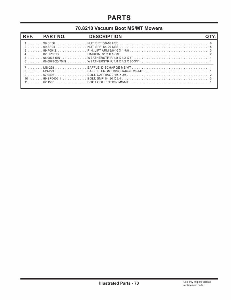
PARTS
Illustrated Parts - 73 Use only original Ventrac replacement parts.
REF. PART NO. DESCRIPTION QTY.1 . . . . . . . . . 99.SF06 . . . . . . . . . . . . . . . . . . .NUT, SRF 3/8-16 USS . . . . . . . . . . . . . . . . . . . . . . . . . . . . . . . . . . . . . . . . . . . . . . . . . . . . . . 6 2 . . . . . . . . . 99.SF04 . . . . . . . . . . . . . . . . . . .NUT, SRF 1/4-20 USS . . . . . . . . . . . . . . . . . . . . . . . . . . . . . . . . . . . . . . . . . . . . . . . . . . . . . . 5 3 . . . . . . . . . 99.F0042 . . . . . . . . . . . . . . . . . . .PIN, LIFT ARM 3/8-16 X 1-7/8 . . . . . . . . . . . . . . . . . . . . . . . . . . . . . . . . . . . . . . . . . . . . . . . 3 4 . . . . . . . . . 02.HP0313 . . . . . . . . . . . . . . . . .HAIRPIN, 3/32 X 1-5/8 . . . . . . . . . . . . . . . . . . . . . . . . . . . . . . . . . . . . . . . . . . . . . . . . . . . . . 2 5 . . . . . . . . . 06.0078-5IN . . . . . . . . . . . . . . . .WEATHERSTRIP, 1/8 X 1/2 X 5” . . . . . . . . . . . . . . . . . . . . . . . . . . . . . . . . . . . . . . . . . . . . . 1 6 . . . . . . . . . 06.0078-20.75IN . . . . . . . . . . . . .WEATHERSTRIP, 1/8 X 1/2 X 20-3/4” . . . . . . . . . . . . . . . . . . . . . . . . . . . . . . . . . . . . . . . . . 1
7 . . . . . . . . . MS-298 . . . . . . . . . . . . . . . . . . . .BAFFLE, DISCHARGE MS/MT . . . . . . . . . . . . . . . . . . . . . . . . . . . . . . . . . . . . . . . . . . . . . . 1 8 . . . . . . . . . MS-299 . . . . . . . . . . . . . . . . . . . .BAFFLE, FRONT DISCHARGE MS/MT . . . . . . . . . . . . . . . . . . . . . . . . . . . . . . . . . . . . . . . 1 9 . . . . . . . . . 97.0406 . . . . . . . . . . . . . . . . . . . .BOLT, CARRIAGE 1/4 X 3/4 . . . . . . . . . . . . . . . . . . . . . . . . . . . . . . . . . . . . . . . . . . . . . . . . . 2 10 . . . . . . . . 99.SF0406-1 . . . . . . . . . . . . . . . .BOLT, SMF 1/4-20 X 3/4 . . . . . . . . . . . . . . . . . . . . . . . . . . . . . . . . . . . . . . . . . . . . . . . . . . . . 3 11 . . . . . . . . . 62.1505 . . . . . . . . . . . . . . . . . . . .BOOT COLLECTION MS/MT . . . . . . . . . . . . . . . . . . . . . . . . . . . . . . . . . . . . . . . . . . . . . . . . 1
70.8210 Vacuum Boot MS/MT Mowers
Warranty - 74
LIMITED WARRANTY - VENTRAC COMMERCIAL EQUIPMENT
WARRANTY
Venture Products, Inc., (henceforth referred to as V.P.I.) warrants on the terms and conditions herein, that it will repair, replace, or adjust any part manufactured by Venture Products Inc., and found by Venture Products, Inc., to be defective in material and/or workmanship during the applicable warranty term.All Ventrac commercial equipment purchased and registered on or after January 1, 2019 will carry a 2-year commercial warranty. The warranty period begins on the date of original customer purchase:
Ventrac Commercial Equipment Warranty Term2100 SSV & Attachments 2-year3000 Series Tractors & Attachments 2-year4000 Series Tractors & Attachments 2-year
All Ventrac add-on kits and accessories such as: 3-point hitch, 12V front & rear power outlets, foot pedal, dual wheel kit, etc., will be covered under the above warranty periods provided they are installed by an Authorized Ventrac Dealer. This warranty may be transferred and will carry the remainder of the warranty starting from the original purchase/registration date with the dealership and/or V.P.I. The engine warranty is covered by its respective engine manufacturer. Please refer to the engine manufacturer’s warranty statement that is included in the owner’s manual.For warranty consideration on Ventrac commercial equipment, including any defective part, must be returned to an Authorized Ventrac Dealer within the warranty period. The warranty shall extend to the cost to repair or replace (as determined by V.P.I.) the defective part. The expense of pickup and delivery of equipment, service call drive time or any transportation expense incurred for warranty repair is the sole responsibility of the owner and is not covered under warranty by Ventrac and/or V.P.I. Ventrac and V.P.I.’s responsibility in respect to claims is limited to making the required repairs or replacements, and no claim of breach of warranty shall be cause for cancellation or rescission of the contract of sale of any Ventrac equipment. Proof of purchase may be required by the dealer to substantiate any warranty claim. Only warranty work performed and submitted by an Authorized Ventrac Dealer may be eligible for warranty credit.This warranty extends only to Ventrac commercial equipment operated under normal conditions and properly serviced and maintained. The warranty expressly does NOT cover: (a) any defects, damage or deterioration due to normal use, wear and tear, or exposure; (b) normal maintenance services, such as cleaning, lubrication, oil change; (c) replacement of service items, such as oil, lubricants, spark plugs, belts, rubber hoses, bearings or other items subject to normal service replacement; (d) damage or defects arising out of, or relating to abuse, misuse, neglect, alteration, negligence or accident; (e) repair or replacement arising from operation of, or use of the equipment which is not in accordance with operating instructions as specified in the operator’s manual or other operational instructions provided by V.P.I.; (f) repair or replacement arising as a result of any operation from Ventrac equipment that has been altered or modified so as to, in the determination of V.P.I., adversely affect the operation, performance or durability of the equipment or that has altered, modified or affected the equipment so as to change the intended use of the product; (g) repair or replacement necessitated by the use of parts, accessories or supplies, including gasoline, oil or lubricants, incompatible with the equipment or other than as recommended in the operator’s manual or other operational instructions provided by V.P.I.; (h) repairs or replacements resulting from parts or accessories which have adversely affected the operation, performance or durability of the equipment; or (i) damage or defects due to or arising out of repair of Ventrac equipment by person or persons other than an authorized Ventrac service dealer or the installation of parts other than genuine Ventrac parts or Ventrac recommended parts.
WARRANTY
Warranty - 75
LIMITED WARRANTY - VENTRAC COMMERCIAL EQUIPMENTThe sole liability of V.P.I. with respect to this warranty shall be the repair and replacement as set forth herein. V.P.I. shall have no liability for any other cost, loss, or damage. In particular V.P.I shall have no liability or responsibility for: (i) expenses relating to gasoline, oil, lubricants; (ii) loss, cost or expense relating to transportation or delivery of turf equipment from the location of owner or location where used by owner to or from any Authorized Ventrac Dealer; (iii) travel time, overtime, after hours’ time or other extraordinary repair charges or charge relating to repairs or replacements outside of normal business hours at the place of business of an Authorized Ventrac Dealer; (iv) rental of like or similar replacement equipment during the period of any warranty repair or replacement work; (v) any telephone or telegram charges; (vi) loss or damage to person or property other than that covered by the terms of this warranty; (vii) any claims for lost revenue, lost profit or additional cost or expense incurred as a result of a claim of breach of warranty; or (viii) attorney’s fees.The remedies of buyer set forth herein are exclusive and are in lieu of all other remedies. The liability of V.P.I., whether in contract, tort, under any warranty, or otherwise, shall not extend beyond its obligation as set forth herein. V.P.I. shall not be liable for cost of removal or installation nor shall V.P.I. be responsible for any direct, indirect, special or consequential damages of any nature. In no event shall V.P.I. be liable for any sum in excess of the price received for the goods for which liability is claimed.There are no representations or warranties which have been authorized to the buyer of the Ventrac commercial equipment other than set forth in this warranty. Any and all statements or representations made by any seller of this equipment, including those set forth in any sales literature or made orally by any sales representative, are superseded by the terms of this warranty. Any affirmation of fact or promise made by V.P.I. or any of its representatives to the buyer which relates to the goods that are the subject to this warranty shall not be regarded as part of the basis of the bargain and shall not be deemed to create any express warranty that such goods shall conform to the affirmation or promise.No employee, distributor, or representative is authorized to change the foregoing warranties in any way or grant any other warranty on behalf of V.P.I.Some states do not allow limitations on how long an implied warranty lasts or allow the exclusion on limitation of incidental or consequential damages, so the above limitation or exclusion may not apply to you.This warranty gives you specific legal rights, and you may also have other rights which vary from state to state.This warranty applies to all Ventrac commercial equipment sold by Venture Products Inc.