
OPERATOR’S AND ORGANIZATIONAL MAINTENANCE MANUAL ...
55
*TM 11-5830-221-12 D E P A R T M E N T O F T H E A R M Y T E C H N I C A L M A N U A L OPERATOR’S AND ORGANIZATIONAL MAINTENANCE MANUAL INTERCOMMUNICATION STATIONS LS-147A/Fl, LS-147B/Fl, LS-147C/Fl, AND LS-147D/Fl Headquarters, Department of the Army, Washington 25, D.C. 5 June 1961 WARNING HIGH VOLTAGE is used in the operation of this equipment. DEATH ON CONTACT may result if operating personnel fail to observe safety precautions. DON’T TAKE CHANCES! Be careful when working on the 115-volt ac line connections. Turn off the power and disconnect the line cord plug from the ac source before making any connections or before working inside the cabinet. Be- fore connecting the LS-147(*)/FI to a 115- volt ac source, be sure that the chassis is connected to the same ground as the ac source. • This manual supersedes TM 11-5830-221-12, 7 December 1959. 1
Transcript of OPERATOR’S AND ORGANIZATIONAL MAINTENANCE MANUAL ...
*TM 11-5830-221-12
D E P A R T M E N T O F T H E A R M Y T E C H N I C A L M A N U A L
O P E R A T O R ’ S A N D O R G A N I Z A T I O N A L M A I N T E N A N C E M A N U A L
I N T E R C O M M U N I C A T I O N S T A T I O N S L S - 1 4 7 A / F l , L S - 1 4 7 B / F l ,
LS-147C/F l , AND LS-147D/F l
Headquarters, Department of the Army, Washington 25, D.C.
5 June 1961
W A R N I N G
HIGH VOLTAGEi s u s e d i n t h e o p e r a t i o n
o f t h i s e q u i p m e n t .
DEATH ON CONTACTm a y r e s u l t i f o p e r a t i n g
p e r s o n n e l f a i l t o o b s e r v e
s a f e t y p r e c a u t i o n s .
DON’T TAKE CHANCES!B e c a r e f u l w h e n w o r k i n g o n t h e 1 1 5 - v o l t
a c l i n e c o n n e c t i o n s . T u r n o f f t h e p o w e ra n d d i s c o n n e c t t h e l i n e c o r d p l u g f r o m t h e
a c s o u r c e b e f o r e m a k i n g a n y c o n n e c t i o n s
o r b e f o r e w o r k i n g i n s i d e t h e c a b i n e t . B e -f o r e c o n n e c t i n g t h e L S - 1 4 7 ( * ) / F I t o a 1 1 5 -
v o l t a c s o u r c e , b e s u r e t h a t t h e c h a s s i s i s
c o n n e c t e d t o t h e s a m e g r o u n d a s t h e a c
s o u r c e .
• T h i s m a n u a l s u p e r s e d e s T M 1 1 - 5 8 3 0 - 2 2 1 - 1 2 , 7 D e c e m b e r 1 9 5 9 .
1


TM 11-5830-221-12C3
Change
No. 3
HEADQUARTERSDEPARTMENT OF THE ARMY
Washington, DC, 14 September 1979
Operator’s and Organizational Maintenance ManualINTERCOMMUNICATION STATIONS
LS-147A/Fl, LS-147B/Fl, LS-147C/Fl AND LS-147D/Fl(NSN 5830-00-752-5357)
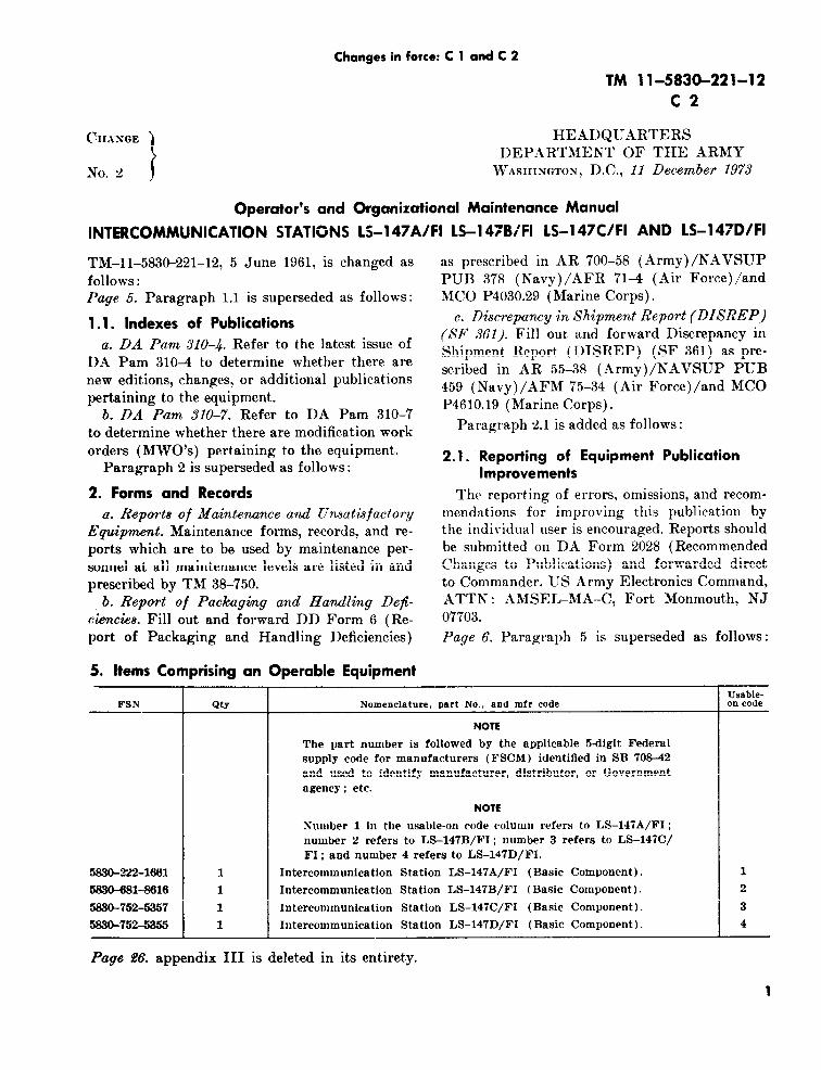
TM 11-5830-221-12, 5 June 1961, is changed asfollows :
The title of the manual is changed as shown above.
Page 5. Paragraphs 2b and 2C are superseded asfollows:
b. Report of Packaging and Handling Deficiencies.Fill out and forward DD Form 6 (Packaging Im-provement Report) as prescribed in AR 700-58/NAVSUPINST 4030.29/AFR 71-13/MCO P40-30.29A and DLAR 4145.8.
c. Discrepancy in Shipment Report (DISREP)(SF 361). Fill out and forward Discrepancy in Ship-ment Report (DISREP) (SF 361) as prescribed inAR 55-38/NAVSUPINST 4610.33B/AFR 75-18/MCO P4610.19C and DLAR 4500.15.
Paragraph 2.1 is superseded as follows:
2.1 Reporting Errors and Recommending Improve-ments
You can help improve this manual. If you find anymistakes or if you know of a way to improve theprocedures, please let us know. Mail your letter, orDA Form 2028 (Recommended Changes to Pub-lications and Blank Forms) to Commander, USArmy Communications and Electronics MaterielReadiness Command, ATTN: DRSEL-ME-MQ,Fort Monmouth, NJ 07703. A reply will be furnisheddirect to you.
Paragraph 2.2 is added after 2.1:
2.2 Reporting Equipment Improvement Recommend-ations (EIR)
If your LS-147( )/FI needs improvement, letus know. Send us an EIR. You, the user, are theonly one who can tell us what you don’tlike about your equipment. Let us know why youdon’t like the design. Tell us why a procedure ishard to perform. Put it on an SF 368 (QualityDeficiency Report). Mail it to: Commander, US
Army Communications and Electronics MaterielReadiness Command, ATTN: DRSEL-ME-MQ,Fort Monmouth, NJ 07703. We’ll send you a reply.
The maintenance duties assigned to the operatorof the LS-147(*)/FI are listed below together with areference to the paragraph covering the specificmaintenance function. The duties assigned require nospecial tools or test equipment.
a. Operator’s preventive maintenance checks andservices chart (para 14.2).
b. Visual inspection (para 15).
c. Troubleshoot ing by use of the equipmentperformance checklist (para 16).
d. Replacing fuses (para 17).
14. Operator’s Preventive Maintenance
Preventive maintenance is the systematicservicing, and inspection of equipment to preventthe occurrence of trouble, to reduce downtime, andto assure that the equipment is in serviceablecondition. To assist in maintaining serviceability,the chart (para 14.2) indicates what to check, howto check , and what the normal condit ions are . I fthe defect cannot be remedied , h igher categorymaintenance , or repair is required. Records andreports of these checks and services must be made in
a c c o r d a n c e w i t h r e q u i r e m e n t s s e t f o r t h i n T M38-750. The procedures g iven in paragraph 14 .2cover routine systematic care for proper upkeep andoperation of the equipment.
14.1 Operator’s Preventive Maintenance Checks and
Services Periods
To be sure that your intercommunication stationis ready for your mission, you must perform yourW E E K L Y ( W ) P r e v e n t i v e M a i n t e n a n c e C h e c k sa n d S e r v i c e s ( P M C S ) . W h e n y o u a r e d o i n g a n yPMCS or routine checks, keep in mind the warningsand cautions.
1

TM 11-5830-221-12
NOTESRoutine checks like cleaning, dusting,washing, checking for frayed cables, stowingitems not in use, covering unused recep-tacles and checking for loose screws are notlisted as PMCS checks. They are thingsthat you should do anytime you see theymust be done.
If your equipment must be kept in contin-uous operation, check and service thoseitems that can be checked and servicedwithout disturbing operation. Make thecomplete checks and services when the
equipment can be shut down.
Use the ITEM NO. column in yourPMCS table as a source of numbers for theTM Item No. column on DA Form 2404(Equipment Inspection and MaintenanceWorksheet) in recording results of PMCS.
Deficiencies that cannot be corrected mustbe reported to higher category maintenancepersonnel. Records and reports of pre-ventive maintenance must be made inaccordance with procedures given inTM 38-750.
14.2 Operator’s Preventive Maintenance Checks and Services Chart
NOTES
Perform the following checks before operation and weekly if:1. You are the assigned operator and have not operated the item since the last weekly, or2. You are operating the item for the first time.Perform the checks in the order listed.
2

TM 11-5830-221-12
Paragraph 14.3 is rescinded.
Page 15. Paragraphs 18 and 19 are superseded asfollows:
18. Scope of Organizational Maintenance
The maintenance duties assigned to the organi-zational repair person are listed below, togetherwith reference to the paragraphs covering the specificmaintenance functions. The required tools and testequipment are listed in paragraph 19.
a. Organizational preventive maintenance checksand services chart (para 21.1).
b. Troubleshooting (para 22).
c. Tube testing and replacement (para 23).
d. Removal and replacement of pi lot lamp(para 24).
19. Tools and Test Equipment
The tools and test equipment required for organi-zational maintenance are listed in SECTION IIIo f A P P E N D I X I I , M A I N T E N A N C E A L L O -CATION.
Paragraphs 20, 21, and 21.1 are superseded asfollows :
20. Organizational Preventive Maintenance
Preventive maintenance is the systematic care,servicing, and inspection of equipment to preventthe occurrence of trouble, to reduce downtime, andto assure that the equipment is in. serviceablecondition. To assist in maintaining serviceability, thechart (para 21.1) indicates what to check, how tocheck, and what the normal conditions are. If thedefect cannot be remedied, higher category main-
ITEMNO.
1
2
tenance or repair is required. Records and reportsof these checks and services must be made in ac-cordance with the requirements set forth in TM38-750. The procedures given in paragraph 21.1cover routine systematic care and cleaning forproper upkeep and operation of the equipment.21. Organizational Preventive Maintenance Checksand Service Periods
To be sure that your intercommunication stationis ready for your mission, you must perform yourQUARTERLY (Q) Preventive Maintenance Checksand Services (PMCS). When you are doing anyPMCS or routine checks, keep in mind the warningsand cautions.
NOTES
Routine checks like cleaning, dusting,washing, checking for frayed cables, stowingitems not in use, covering unusedreceptacles and checking for loose screwsare not listed as PMCS checks. They arethings that you should do anytime you seethey must be done.
Use the ITEM NO. column in your PMCStable as a source of number for the TMItem No. column on DA Form 2404 (Equip-ment Inspection and Maintenance Work-sheet) in recording results of PMCS.
Deficiencies that cannot be corrected mustbe reported to higher category maintenancepersonnel. Records and reports of pre-ventive maintenance must be made inaccordance with procedures given in TM38-750.
21.1 Organizat ional Prevent ive Maintenance Checks and Services Chart
NTERVALQ
X
X
(Q) Quarterly
ITEM TO BE PROCEDUREINSPECTED
Modifications Check DA Pam 310-7 to determinewhether new applicable MWO's havebeen published, All urgent MWO’smust be applied immediately. Allnorm al MWO’s must be scheduled.
Speaker-Microphone Inspect speaker-microphone cone forcracks or looseness. There should beno evidence of cracks or looseness.
3
the list of references:
DA Pam 310-7 US Army Equipment Indexof Modification Work Or-ders.
Page 22. Appendix II is superseded as follows:
TM 11-5830-221-12
Page 21, Appendix I: The following is added to TM 11-6625-203-12 Operator and Organization-al Maintenance: Mult i -meter AN/U RM-105, andAN/URM-105C IncludingMultimeter ME-77/U andME-77C/U.
APPENDIX IIMAINTENANCE ALLOCATION
Section I. INTRODUCTION
II-1. GeneralThis appendix provides a summary of the main-
tenance operations for Intercommunication StationsLS-147A/FI, LS-147B/FI, LS-147C/FI and LS-147D/FI. It authorizes categories of maintenance forspecific maintenance functions on repairable items andcomponents and the tools and equipment requiredto perform each function. This appendix may beused as an aid in planning maintenance operations.
II-2. Maintenance Function.Maintenance functions will be limited to and definedas follows:
a. Inspect. To determine the serviceability of anitem by comparing its physical, mechanical, and/orelectrical characteristics with established standardsthrough examination.
b. Test. To verify serviceability and to detectincipient failure by measuring the mechanical orelectrical characteristics of an item and comparingthose characteristics with prescribed standards.
c. Service. Operations required periodically tokeep an item in proper operating condition, i.e., toclean (decontaminate), to preserve, to drain, to paint,or to replenish fuel, lubricants, hydraulic fluids, orcompressed air supplies.
d. Adjust. To maintain, within prescribed limits,by bringing into proper or exact position, or bysetting the operating characteristics to the specifiedparameters.
e. Align. To adjust specified variable elements ofan item to bring about optimum or desired perform-ance.
f. Calibrate. To determine and cause correctionsto be made or to be adjusted on instruments or testmeasuring and diagnostic equipments used in pre-
4
cision measurement. Consists of comparisons of twoinstruments, one of which is a certified standard ofknown accuracy, to detect and adjust any dis-crepancy in the accuracy of the instrument beingcompared.
g. Install. The act of emplacing, seating, or fixinginto position an item, part, module (component orassembly) in a manner to allow the proper functioningof the equipment or system.
h. Replace. The act of substituting a serviceablelike type part, subassembly, or module (componentor assembly) for an unserviceable counterpart.
i. Repair. The application of maintenance serv-ices (inspect, test, service, adjust, align, calibrate,replace) or other maintenance actions (welding,grinding, riveting, straightening, facing, remachining,or resurfacing) to restore serviceability to an item bycorrecting specific damage, fault, malfunction, orfailure in a part, subassembly, module (componentor assembly), end item, or system.
j. Overhaul. That maintenance effort (service/action) necessary to restore an item to a completelyserviceable/operational condition as prescribed bymaintenance standards (i.e., DMWR) in appropriatetechnical publications. Overhaul is normally thehighest degree of maintenance performed by theArmy. Overhaul does not normally return an item tolike new condition.
k. Rebuild. Consists of those services/actionsnecessary for the restoration of unserviceableequipment to a like new condition in accordance withoriginal manufacturing standards. Rebuild is thehighest degree of materiel maintenance applied toArmy equipment. The rebuild operation includes theact of returning to zero those age measurements(hours, miles, etc.) considered in classifying Armyequipments/components.
TM 11-5830-221-12
II-3. Column Entries.
a. Column 1, Group Number. Column 1 lists groupnumbers, the purpose of which is to identify compo-nents, assemblies, subassemblies, and modules withthe next higher assembly.
b. Column 2, Component/Assembly. Column 2contains the noun names of components, assemblies,subassemblies, and modules for which maintenance isauthorized.
c. Column 3, Maintenance Functions. Column 3lists the functions to be performed on the item listedin column 2. When items are listed without main-tenance functions, it is solely for purpose of havingthe group numbers in the MAC and RPSTL coincide.
d. Column 4, Maintenance Category. Column 4specifies, by the listing of a “worktime” figure in theappropriate subcolumn(s), the lowest level of main-tenance authorized to perform the function listed incolumn 3. This figure represents the active timerequired to perform that maintenance function atthe indicated category of maintenance. If thenumber or complexity of the tasks within the listedmaintenance function vary at different maintenancecategories, appropriate ‘‘worktime” figures will beshown for each category. The number of task-hoursspecified by the “worktime” figure represents theaverage time required to restore an item (assembly,subassembly, component, module, end item orsystem) to a serviceable condition under typical fieldoperating conditions. This time includes preparationtime, troubleshooting time, and quality assurance/quality control time in addition to the time requiredto perform the specific tasks identified for themaintenance functions authorized in the main-tenance allocation chart. Subcolumns of column 4are as follows:
C-Operator/CrewO-OrganizationalF-Direct SupportH-General SupportD-Depot
e. Column 5, Tools and Equipment. Column 5specifics by code, those common tool sets (notindividual tools) and special tools, test, and supportequipment required to perform the designatedfunction.
f. Column 6, Remarks. Column 6 contains analphabetic code which leads to the remark in sectionIV, Remarks, which is pertinent to the item oppositethe particular code.
II-4. Tool and Test EquipmentRequirements (Sect. Ill).
a. Tool and Test Equipment Reference Code. Thenumbers in this column coincide with the numbersused in the tools and equipment column of theMAC. The numbers indicate the applicable tool ortest equipment for the maintenance functions.
b. Maintenance Category. The codes in thiscolumn indicate the maintenance category allocatedthe tool or test equipment.
c. Nomenclature. This column lists the nounname and nomenclature of the tools and test equip-ment required to perform the maintenance functions.
d. National/NATO Stock Number. This columnlists the National /NATO stock number of thespecific tool or test equipment.
e. Tool Number. This column lists the manu-facturer’s part number of the tool followed by theFederal Supply Code for manufacturers (5-digit)in parentheses.
II-5. Remarks (Sect. IV).a. Reference Code. This code refers to the ap-
propriate item in section II, column 6.
b. Remarks. This column provides the requiredexplanatory information necessary to clarify itemsappearing in section II.
5


TM 11-5830-221-12
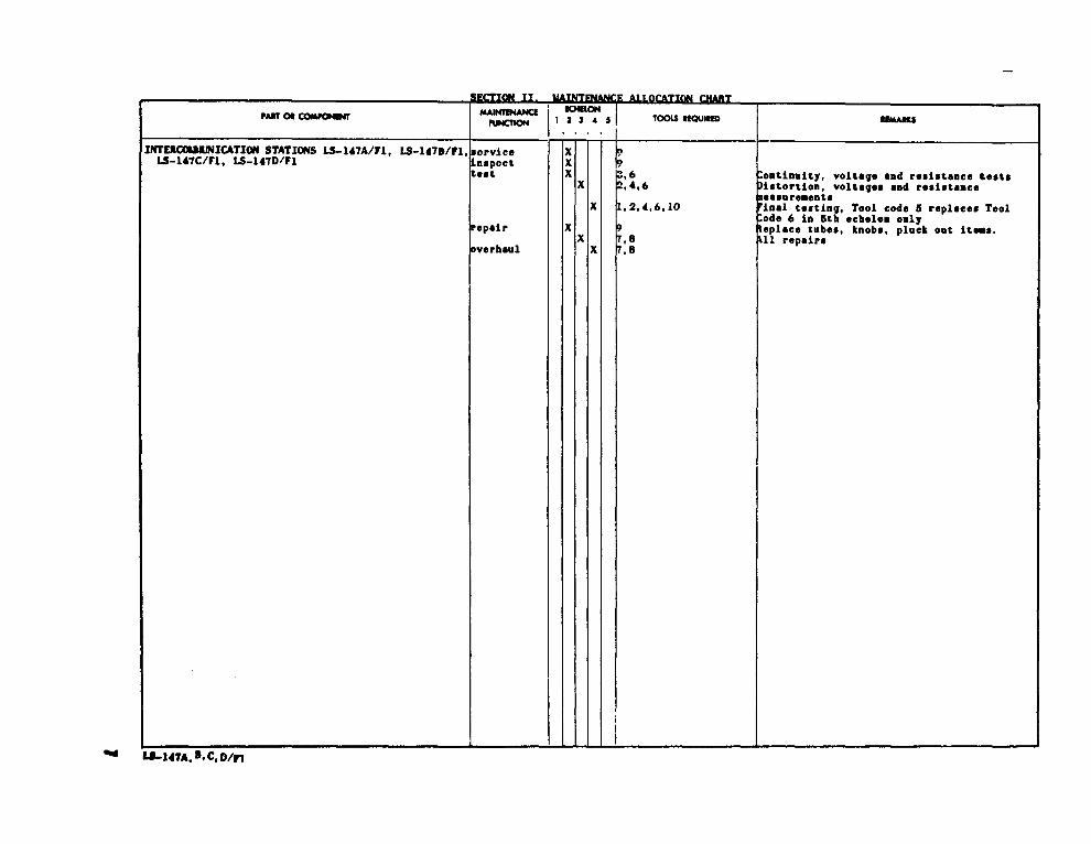
SECTION II MAINTENANCE ALLOCATION CHARTFOR
INTERCC4UWNICATION STATIONS LS-147A, B , C , ANO D/FI
(1) (2) (3)(4)
MAINTENANCE ~TEGORY (5) (6)GRWP COMPONEt41/ASSEMBLY MAINTENANCE TOOIJ3 REMARUS
NUMSER FUNCTION 1 ANOc o F H D
EQPT.
00 INTERCOMMUNICATION STATIONS LS-147A/FI , LS-147S/FI ,LS-147CIF1. ANO LS-1470/F1. Inspect 0.3
Test 0.5Organizational test will be ‘limited to equipment
1,7Tea t 1.0
operation.5 thr~ .0
Orsanizatlonal repair will be limited service 0.5to replacement of fuse, knobs, and tubes.
2Repair 1.0 1,2,7Repair 2.0 3 thru lCOwerhwl 5.0 1 thru lK
Change 3 I1-3

II-4
TM 11-5830-221-12
S E C T I O N I I I TOOL AND TEST EQUIPMENT REQUIREMENTSFOR
1NTERCIHIUN1CATION STATIONS LS-147A, S, C, MID D/FI
“OOL OR TEST MAINTENANCEEOUIPMENT NOMENCLATURE
NATIQNAIJNATo
REF -ECATEGORY STOCK NUMBER TOOL NUMBER
1 0, ?, IS, D MJLTISISTSR AWUSM-1OS 6625-00-581-2036
2 0, F, N. D TOOL KIT, ELSCTRONIC SOUIPNWT TK-101IC 5180-00-064-5178
3 F, N, D TQOL KIT, SLHX’NONIC SQOIPKSNZ TK-1OWC 5180-00-605-0079
4 F, N, D TOOL KIT, SLSCTNONIC SQUXPKSNT TK-105/G S180-00-610-S177
i ~, H, D RULTIKETER AWUSK-223 6625-00-999-7465
6 F, N, O SLSCTNONIC VOL3?ISTER Mt-30(*)/u 6625-00-643-1670
7 0, F, H, D TEST SST, ELECTRON TUS8 2V-7(*)/U 6625-00-S20-0064
8 F, PI, D TSST S2?, ELSCTRON TUSS TV-2(*)/U 6623-00-669-0263
9 F, N. D AUDIO OSCILLATOR TS-382(*)/U 6625-00-151-7479
10 F, H, D SPSCTRUK ANALYZSN TS-723/U 6625-00-66S-9418

By Order of the Secretary of the Army:
Official:
J. C. PENNINCTONMajor General, United States Army
The Adjutant General
DISTRIBUTION:Active Army
USAINSCOM (2)COE (1)TSC (1)USAARENBD (1)DARCOM (1)TRADOC (2)OS Maj Comd (4)TECOM (2)USACC (4)MDW (1)Armies (2)Corps (2)Svc Colleges (1)USASICS (5)USAADS (2)USAFAS (2)USAARMS (2)USAIS (2)USAES (2)USAICS (3)MAAG (1)USARMIS (1)USAERDAA (1)USAERDAW (1)Fort Gillem (10)Fort Gordon (10)Fort Carson (5)Fort Huachuca (10)Ft Monmouth(HISA) (21)Ft Richardson(ECOM) (2)Army Dep (1) except
LBAD (14)SAAD (30)TOAD (14)SHAD (3)USA Dep (1)Sig Sec USA Dep (1)
TM 11-5830-221-12
E. C. MEYERGeneral, United States Army
Chief of Staff
Units org under fol TOE:(1 cy each unit, UNOINDC)29-207 (2)29-610 (2)79-4711-1511-1611-3611-3711-3811-8511-8611-9611-9711-9811-11711-13711-30211-500(AA-AC)1729-13429-1363744-43544-43644-43744-53544-53644-53744-546
ARNG: NoneUSAR: None
For explanation of abbreviations used, see AR 310-50.
7


C H A P T E R 1 .Sec t i on I .
II.
C H A P T E R 2 .Sec t i on I .
II.
C H A P T E R 3 .Sec t i on I .
II.
C H A P T E R 4 .
Sec t i on I .
II.
A P P E N D I X I .II.
III.
GeneralScope . . . . . . . . . . . . . . . . . . . . . . . . . . . . . . . . . . . . . . . . . . . .Forms and records . . . . . . . . . . . . . . . . . . . . . . . . . . . . . . . . . . . .Description and dataPurpose anduse . . . . . . . . . . . . . . . . . . . . . . . . . . . . . . . . . . . . .Technical characteristics . . . . . . . . . . . . . . . . . . . . . . . . . . . . . . .Table of components . . . . . . . . . . . . . . . . . . . . . . . . . . . . . . . . . .Description . . . . . . . . . . . . . . . . . . . . . . . . . . . . . . . . . . . . . . . .Differences in models.. . . . . . . . . . . . . . . . . . . . . . . . . . . . . . . .INSTALLATION AND OPERATIONService upon receipt of equipmentUnpacking and checking . . . . . .Installation . . . . . . . . . . . . . . .OperationControls and indicator . . . . . . . .Operation under usual conditions .Operation under unusual conditionsMAINTENANCE INSTRUCTIONSOperator’s maintenanceScope of operator’s maintenance . .Preventive maintenance . . . . . . .Visual inspection . . . . . . . . . .Equipment performance checklist .Replacing fuses . . . . . . . . . . . .Organizational maintenance
. . . . . . . . . . . . . . . . . . . . . . . . .
. . . . . . . . . . . . . . . . . . . . . . . . .
. . . . . . . . . . . . . . . . . . . . . . . . .
. . . . . . . . . . . . . . . . . . . . . . . . .
. . . . . . . . . . . . . . . . . . . . . . . . .
. . . . . . . . . . . . . . . . . . . . . . . . .
. . . . . . . . . . . . . . . . . . . . . . . . .
. . . . . . . . . . . . . . . . . . . . . . . . .
. . . . . . . . . . . . . . . . . . . . . . . . .
. . . . . . . . . . . . . . . . . . . . . . . . .
Scope of organizational maintenance . . . . . . . . . . . . . . . . . . . . . . . .Tools and test equipment . . . . . . . . . . . . . . . . . . . . . . . . . . . . . . .Preventive maintenance . . . . . . . . . . . . . . . . . . . . . . . . . . . . . . . .Visual inspection . . . . . . . . . . . . . . . . . . . . . . . . . . . . . . . . . . .Troubleshooting checklist . . . . . . . . . . . . . . . . . . . . . . . . . . . . . . .Tube testing and replacement. . . . . . . . . . . . . . . . . . . . . . . . . . . .Removal and replacement of pilot lamp . . . . . . . . . . . . . . . . . . . . . .SHIPMENT AND LIMITED STORAGE AND DEMOLITION
TO PREVENT ENEMY USEShipment and limited storageDisassembly of equipment . . . . . . . . . . . . . . . . . . . . . . . . . . . . . . .Repacking for shipment of limited storage . . . . . . . . . . . . . . . . . . . .Demolition of material to prevent enemy useAuthority for demolition . . . . . . . . . . . . . . . . . . . . . . . . . . . . . . . .Methods of destruction . . . . . . . . . . . . . . . . . . . . . . . . . . . . . . . . . . . . .. . . . . . . . . . . . . ..
Paragraph
INTRODUCTION
12
34567
89
101112
1314151617
18192021222324
2526
2728
Page
55666666
77799
1010
1111111111121515151515151616
20202020202021REFERENCES . . . . . . . . . . . . . . . . . . . . . . . . . . . . . . . . . . . . . . . . . . .
MAINTENANCE ALLOCATION. . . . . . . . . . . . . . . . . . . . . . . . . . . . . . . . 22BASIC ISSUE ITEMS . . . . . . . . . . . . . . . . . . . . . . . . . . . . . . . . . . . . . . . 26
3
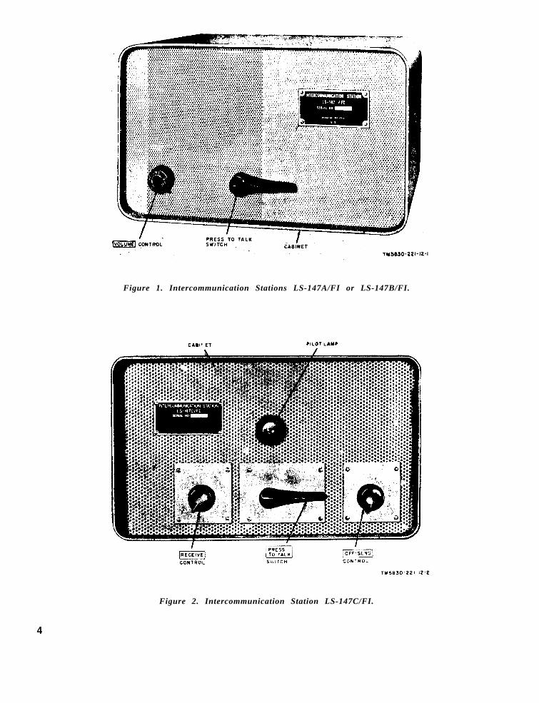
Figure 1. Intercommunication Stations LS-147A/FI or LS-147B/FI.
Figure 2. Intercommunication Station LS-147C/FI.
4

CHAPTER 1INTRODUCTION
Section I. GENERAL
1. Scope 2. Forms and Records
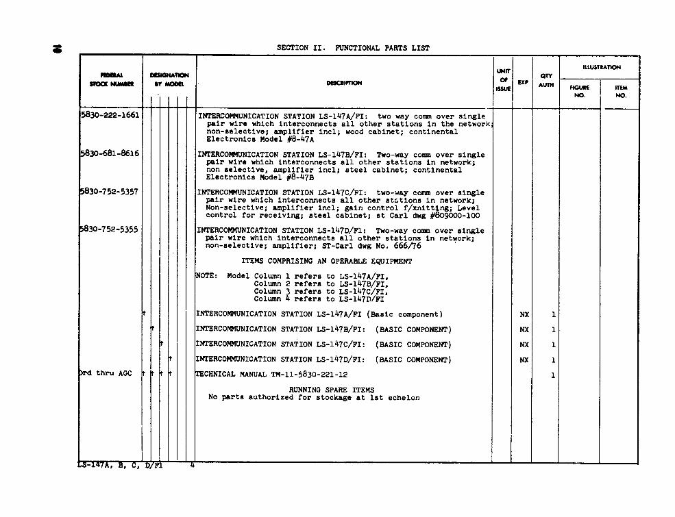
a. This manu a l des c r i b es In t e r commu- a . Unsat i s fac tory Equipment Repor t .
ni ca t i on S ta t i ons LS -147A /FI , LS -147B / (1)FI, LS-147C/FI, and LS-147D/FI and cov-ers their installation, operation, and oper-ator ’s and organizational maintenance. Itincludes operation under usual and unusualcondit ions, c leaning and inspection of theequipment, and replacement of parts avail-able for f irst and second echelon mainte-nance.
(2)
b. Offic ial nomenclature fo l lowed by (*)is used to indicate all models of the equip-ment i tem covered in this manual . Thus,In te r communica t i on S ta t i on LS -147 (* ) /F Irepresents In te r communica t i on S ta t i ons
Fill out and forward DA Form 468(Unsatisfactory Equipment Report)t o the Commanding Of f i c e r , U .S .A r m y S i g n a l M a t e r i e l S u p p o r tA g e n c y , A T T N : S I G M S - M L , F o r tMonmouth, N.J. , as prescribed inA R 7 0 0 - 3 8 .
Fi l l out and forward AF TO Form29 (Unsatisfactory Report) to theC o m m a n d e r , A i r M a t e r i e l C o m -mand, Wright-Patterson Air ForceBase , Oh io , a s p res c r ibed in AFT O 0 0 - 3 5 D - 5 4 .
L S - 1 4 7 A / F I , L S - 1 4 7 B / F I , L S - 1 4 7 C / F I , b. Report of Damaged or Improper Ship-and LS-147D/FI. ment. Fill out and forward DD Form 6 (Re-
Figure 3. intercommunication Station LS-147D/FI.
5

port of Damaged or Improper Shipment) asp r e s c r i b e d i n A R 7 0 0 - 5 8 ( A r m y ) , N a v yShipping Guide, Article 1850-4 (Navy), andAFR 71 -4 (A i r For ce ) .
c . Prevent ive Maintenance Forms . P r e -pare DA Form 11-238 (fig. 5 and 6) (Main-tenance Check List for Signal Equipment(Sound Equipment, Radio, Direct ion Find-ing, Radar, Carrier, Radiosonde and Tele-vision)) in accordance with instructions onpage 1 of the form.
d. Parts List Form. F o r w a r d D A F o r m
2028 (Recommended Changes to DA Tech-nical Manual Parts Lists or Supply Manual7, 8, or 9) direct to the Commanding Offi-c e r , U .S . Army S igna l Mater i e l Suppor tA g e n c y , A T T N : S I G M S - M L , F o r t M o n -mouth, N.J. , for comments on appendixesII and III.
e . Comments on Manual. Forward a l lother comments on this publication directt o t h e C o m m a n d i n g O f f i c e r , U . S . A r m ySigna l Mater i e l Suppor t Agency , ATTN:SIGMS-PA2d, Fort Monmouth, N.J.
Section Il. DESCRIPTION AND DATA
3. Purpose and Use
T h e L S - 1 4 7 ( * ) / F I p r o v i d e s t w o - w a ya u d i o c o m m u n i c a t i o n s b e t w e e n t w o o rm o r e p o i n t s . T h e L S - 1 4 7 ( * ) / F I m a y b eu s e d i n a n i n t e r c o m m u n i c a t i o n s y s t e mf o r a m a x i m u n o f s e v e n s h e l t e r s o r o f -f i c e s .
4. Technical Characteristics
Power output. . . . . . . 4 watts.Input and output re-
sistances . . . . . . . . 12 ohms (maX).V o l t a g e r e q u i r e -
merits . . . . . . . . . . 1 1 5 v o l t s a c ,60 CPS.
Power consumption:L S - 1 4 7 A / F I , L S -
147B/FI, and LS-147D/FI . . . . . . 32 watts.
LS-147C/FI . . . . . 40 watts.Note. No power is required for reception alone
Weight . . . . . . . . . . . . . . 11 lbs.
Number of vacuumtubes . . . . . . . . . . . 3.
5. Table of Components
The components of the LS-147(*) /FI anda l ist of running spares are provided inappendix III.
6. Description
The LS-147(*) /FI ( f ig . 1 , 2 , and 3) is asel f -contained unit . Al l operating controlsare located on the front panel and all sig-nal and power connections are located onthe rear panel ( f ig . 7 , 8 , and 9) . The ex-t e rna l d i f f e rences in mode l s o f the LS -147(*)/FI are listed in paragraph 7.
7. Differences in Models
All models of the LS-147(*)/FI are simi-lar in size, shape, and general appearance.The external di f ferences are l isted in thechart below.
Item
CabinetPilot lamp locationRECEIVE controlPower cord ground
leadBinding posts
LS-147A/FI
WoodBehind front panelNot includedNot included
screw-type
LS-147B/FI LS-147C/FI
MetalBehind front panelNot includedNot included
Screw-type
MetalOn front panelIncludedIncluded
Push-type (rubber-covered)
LS-147D/FI
MetalOn front panelIncludedIncluded
Screw-type
6

CHAPTER 2INSTALLATION AND OPERATION
Section I. SERVICE UPON RECEIPT OF EQUIPMENT
8. Unpacking and Checking(fig. 4)
a. Packaging Data. Figure 4 i l lustratesa typical method of packaging and packingthe LS-147(*)/FI. The wooden packing caseis approximately 9 inches deep, 9 incheshigh, and 13 inches long. The volume of thepackaged unit is approximately 0.61 cubicfeet , and the weight is approximately 15pounds .
b . Remov ing Cont en t s .(1)
(2)
(3)
Cut the metal straps just below thew o o d e n c o v e r .U s e a n a i l p u l l e r a n d r e m o v e t h enai ls from the wooden cover .
C a u t i o n : Do not attempt to pryo f f t h e w o o d e n c o v e r . T o o l s u s e dfor prying wil l damage the equip-m e n t .
Remove the wooden cover and fo l -low the procedures in (a) b e l o w i fthe equipment is packed for exportshipment or (b) below if the equip-m e n t i s p a c k a g e d f o r d o m e s t i csh ipment .
(a) Open the outer corrugated cartona n d s l i t t h e w a t e r - v a p o r p r o o fb a r r i e r .
(b) Sl i t the waterproo f case l iner .(4) Open the inner corrugated carton
and remove the contents.c . Check ing .
(1) Inspect the equipment for any lossor damage that may have occurredduring shipment. I f the equipmenthas been damaged or is incomplete,refer to paragraph 2.
(2) Check the equipment against thepacking l ist . When no packing l ista c c o m p a n i e s t h e e q u i p m e n t , a p -pendix III may be used as a generalcheck to indicate the equipment thatprobably has been packed.
(3)
(4)
Check the front-panel controls tobe sure that they operate withoutbinding.C h e c k t h e p o w e r c o r d f o r c u t s ,breaks, or other damage.
(5) Check to be sure that the propersize (1 ampere) fuse has been in-s ta l l ed .
(6) If the equipment has been used orreconditioned, check to see whetherit has been changed by a modifica-t i on work o rder (MWO) . I f mod -ified, the MWO number will appearon the front panel, near the nomen-clature plate.
9. Installation.
To install the LS-147(*)/FI in a shelter,follow the procedures given in a below. Toinstall the LS-147(*)/FI in an office, fol-low the procedures in b below. I f the LS-1 4 7 ( * ) / F I i s p r e i n s t a l l e d i n a s h e l t e r ,check to see that the procedures in a b e l o whave been completed.
Note. The procedures described below should beperformed by organizational maintenance personnel.
a. Shelter .(1)
(2)
Instal l the LS-147(*) /FI at the lo-cation where i t is to be operated.If mounting brackets are provided,secure the unit in position with themounting brackets .Connect the chassis to shelterg r o u n d . C o n n e c t t h e L S - 1 4 7 C / F Ipower cord ground lead (fig. 8) andthe LS-147D/FI power cord groundlead (fig. 9) to a ground connectionat or near the alternating current(ac) outlet , For connection of theL S - 1 4 7 A / F I a n d t h e L S - 1 4 7 B / F Ichassis to ground, obtain a lengthof wire equipped with spade lugs onboth ends. Connect and secure ones p a d e l u g b e t w e e n t h e h e x a g o n a l
7
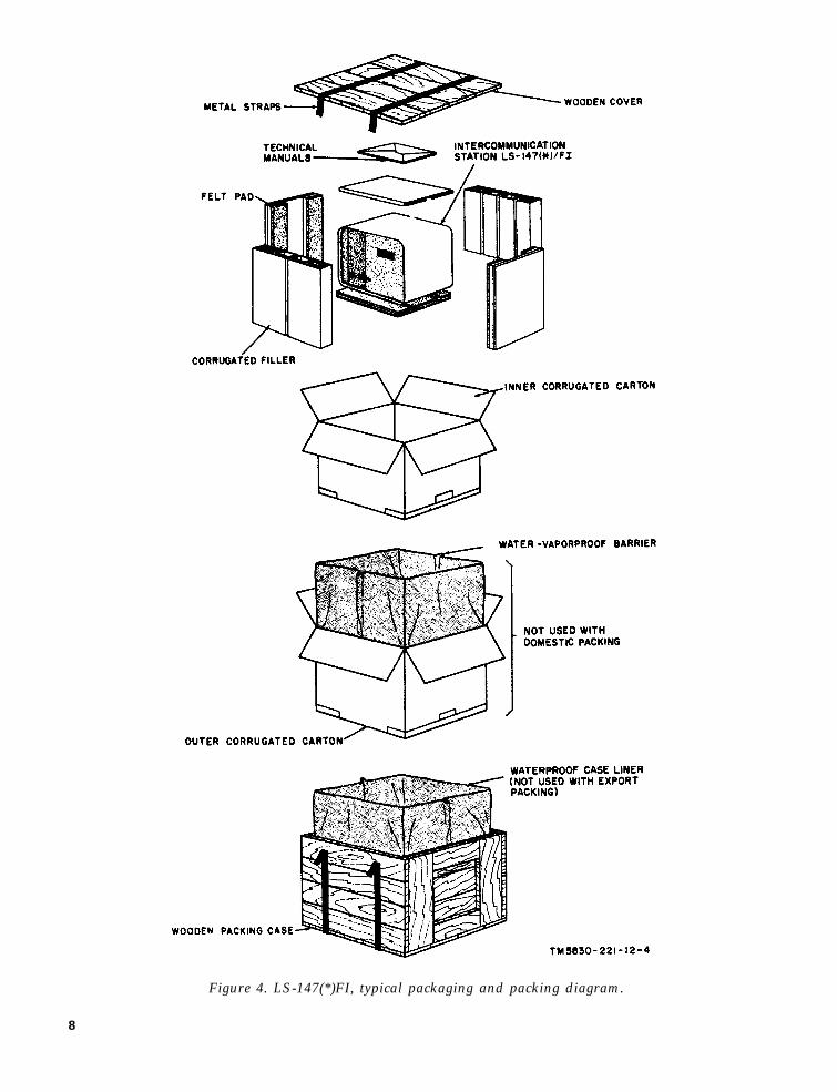
Figure 4. LS-147(*)FI, typical packaging and packing diagram.
8

nuts on the ground terminal at the b . Of f i c e .
(3)
(4)
rear panel of the unit (fig. 7); con- (1)nect the other spade lug to a groundconnection at or near the ac outlet.
Connect a twisted pair of wires tothe two binding posts on the rearpanel of the unit. The twisted pairmust be long enough to be connected
(2)
to another LS-147(*)/FI at a distantl o c a t i o n . U s e s h e l t e r w i r i n g , i f
(3)
p r o v i d e d , f o r t h e w i r e - p a i r c o n -nec t i on a t the b ind ing pos t s . A l lstat ions in the loop must be con-nected in paral le l .
C o n n e c t t h e p o w e r c o r d p l u g t o
Position the unit on a desk, table,or other flat surface where it is tobe operated.
Caution: Place the unit so that itcannot be accidental ly knocked of fi ts location.Connec t the chass i s t o g round (a(2) above) .Connect a twisted pair of wires tothe two binding posts on the rearpanel of the unit. The twisted pairmust be long enough to be connectedto another LS-147(*)/FI at a distantl o c a t i o n . A l l s t a t i o n s i n t h e l o o pmust be connected in parallel.
10. Controls and Indicator
a. LS-147A/FI and LS-147B/FI (fig. 1).
Control or indicator Function
VOLUME control:On-off switchPotentiometer
Press to talk switch (two-positionnonlocking lever switch)
Pilot lamp (incandescent-type)
Position Action
OFF (clockwise). Disconnects power from the unit.HI-LO. Controls volume to all other units in
the system.Talk (depressed position). Permits the operator to talk to all
other stations in the system.Listen (nondepressed position). Permits the operator to hear all
transmissions in the system.When lighted, indicates that power is
applied to unit.
b. LS-147C/FI and LS-147D/FI (fig, 2 and 3).
Control or indicator Function
OFF-SEND control:On-off switch . . . . . . . . . . . . . . . .
Potentiometer, . . . . . . . . . . . . . . . . .
RECEIVE control (potentiometer).
PRESS TO TALK switch (Two-position nonlocking lever switch)
Pilot lamp (neon-type).. . . . . . . . . .
Position Action
OFF (clockwise on LS-147D/FI);(counterclockwise on LS-147C/FI).
1-10 (to increase volume turncontrol clockwise).
1-10 (to increase volume, turncontrol clockwise).
Talk (depressed position) . . . . . .
Listen (nondepressed position)..
Disconnects power from the unit.
Controls volume to all other units inthe system.
Controls receive volume from distantstation.
Permits the operator to talk to otherstations in the system.
Permits the operator to hear all trans-missions in the system.
When lighted, indicates that power isapplied to unit.
9

11. Operation Under Usual Conditions
a. Calling Distant Station.(1)
(2)
(3)
T u r n t h e V O L U M E c o n t r o l ( L S -1 4 7 A / F I a n d L S - 1 4 7 B / F I ) c o u n -te r c l o ckwise , the OFF-SEND con -t r o l ( L S - 1 4 7 C / F I ) c l o c k w i s e , o rthe OFF-SEND cont ro l (LS -147D/FI) counterclockwise, unti l a c l ickheard ; then pos i t i on the c ont ro lapproximately at its rnidpos ition.The pilot lamp, when lighted, indi-cates that the unit is turned on.D e p r e s s t h e P R E S S T O T A L Kswitch, and speak directly at thefront panel. Speak in a normal tonev o i c e .R e l e a s e t h e P R E S S T O T A L Kswi t ch , and wa i t f o r the d i s tantstation to call.
b. Receiving Call from Distant Station.(1)
(2)
The VOLUME control (LS-147A/FIand LS-147B/FI) or the OF F-SENDcontrol (LS-147C/FI and LS-147D/FI) need not be in the on position toreceive a call, but must be in theo n p o s i t i o n t o a n s w e r o r c a l l adistant station (a a b o v e ) .I f the received call is not at thed e s i r e d v o l u m e l e v e l , a d j u s t t h eRECEIVE cont ro l (LS -147C /FI o rLS-147D/FI ) f o r the des i red vo l -ume. If the received call is not att h e d e s i r e d v o l u m e l e v e l f o r t h eL S - 1 4 7 A / F I o r L S - 1 4 7 B / F I , c a l lthe distant station (a a b o v e ) a n drequest that the transmit volumelevel be readjusted.
c. Stopping. To remove power from theLS-147 (* ) /F I , turn the VOLUME contro l(LS -147A /FI and LS-147B /FI ) c l o ckwise ,the OFF-SEND control (LS-147C/FI) coun-t e r c l o c k w i s e , o r t h e O F F - S E N D c o n t r o l(LS -147D/FI ) c l o ckwise , unt i l a c l i ck i sh e a r d .
12. Operation Under Unusual Conditions
a . G e n e r a l . T h e o p e r a t i o n o f t h e L S -147(*)/FI may be difficult in regions where
extreme cold, heat, humidity, or sand con-d i t i ons preva i l . Un less p recaut i ons weretaken, adverse condit ions may cause pooroperation. The procedures described in bthrough d below wil l minimize the ef fectsof these unusual c l imatic condit ions.
b . Opera t ion in Arc t i c C l imates . S u b -zero temperatures and cl imatic condit ionsassociated with cold weather affect the ef-f ic ient operation of the LS-147(*) /FI . Fol -low the instructions and precautions belowfor opera t i on under such adverse c ond i -t i o n s .
( 1 ) Keep the LS -147 (* ) /F I warm andd r y .
(2 ) A f t e r the LS -147 (* ) /F I has beenexposed to the cold and is broughtinto a warm room, m o is t u-r ewil l col lect on the unit ; this maycause a change in operating char-acterist ics . When the unit reachesr o o m t e m p e r a t u r e , d r y i t t h o r -oughly .
c. Operation in Tropical Climates. H i g hrelative humidity causes condensation tof o rm on the LS -147 (* ) /F I whenever thetemperature of the unit is lower than thatof the surrounding air . To minimize thiscondit ion, provide as much venti lat ion asp o s s i b l e . D r y t h e u n i t t h o r o u g h l y b e f o r eoperating it .
d. Operation in Desert Climates.(1) The main problem that arises with
e q u i p m e n t o p e r a t i o n i n d e s e r tareas is the large amount of sand,dus t , o r d i r t that enters the LS-147 (* ) /F I chass i s .
(2) Be careful to keep the unit as freef rom dus t as poss ib l e . Make f r e -quent preventive maintenancechecks (para 14) . This equipmentd o e s n o t r e q u i r e l u b r i c a t i o n a n ds h o u l d b e k e p t f r e e f r o m o i l a n dgrease. Dust, sand, and dirt thatcome in contact with oil or greaseresults in grit , which wil l damagethe unit.
10

CHAPTER 3
MAINTENANCE INSTRUCTIONS
Section I. OPERATOR’S MAINTENANCE
13. Scope of Operator’s Maintenance
The fol lowing is a l ist of maintenanceduties normally performed by the operatorof the LS-147(*) /FI. These procedures donot require special tools or test equipment.
a. Preventive maintenance (para 14) .b. Visual inspection (para 15) .c. Troubleshooting, by use of the equip-
ment performance checklist (para 16) .d. Replacing fuses (para 17) .
14. Preventive Maintenance
a. DA Form 11-238. Items 1 through 12on DA Form 11-238 (fig. 5 and 6) constitutea preventive maintenance checklist to beused by the operator. Items not applicableto the LS-147(*)/FI are lined out in figures5 and 6. References in the ITEM block inthe f igures refer to paragraphs that con-t a i n a d d i t i o n a l m a i n t e n a n c e i n f o r m a t i o npertinent to the particular item. Instruc-tions for use of the form appear on page 1of the form.
b. Items. The information in the fo l low-ing char t i s supp lementary t o DA Form11 -238 . The i t em numbers c o r respond t othe ITEM numbers on the form.
Item
2
3
10
Maintenance procedures
Remove dust, dirt, grease, and moisturefrom the outside of the cabinet with aclean, dry, lint-free cloth.
Operate the PRESS TO TALK switch andcheck to see that it returns to the listen(nondepressed) position.
Check all controls to make sure that theyoperate smoothly.
Inspect the power cord plug for properconnection to the ac outlet.
Check for proper ground connections on thechassis (par 9a(2)).
Check the binding post connections for se-cure connections of signal line wires.
15. Visual Inspection
a. When the LS -147 (* ) /F I f a i l s t o per -f o rm proper ly , check a l l the c ond i t i onsl isted below. Do not check any item withthe power on.
( 1 ) W r o n g s e t t i n g o f c o n t r o l s a n dswitches (para 10) .
( 2 ) B a d c h a s s i s g r o u n d c o n n e c t i o n s(para 9).
( 3 ) D i s connec ted power co rd p lug a tthe ac outlet.
(4) Loose or disconnected binding postc o n n e c t i o n s .
(5) Burned-out fuse (para 17) .
b. If the above checks do not restore theLS-147 (* ) /F I t o normal opera t i on , r e f e rt h e e q u i p m e n t t o h i g h e r e c h e l o n f o r r e -p a i r .
16. Equipment Performance Checklist
a. General. T h e e q u i p m e n t p e r f o r m a n c echecklist is used to systematical ly checke q u i p m e n t p e r f o r m a n c e . A l l c o r r e c t i v emeasures that the operator is authorizedto per f o rm are g iven in the Correc t i vemeasures c o lumn. I f these measures donot correct the fault , addit ional mainte-nance must be performed by higher-eche-lon maintenance personnel having requiredtoo l s , t e s t equ ipment , and sk i l l . In th i scase, note on the repair tag how the equip-m e n t p e r f o r m e d a n d w h a t c o r r e c t i v emeasures were taken.
b. Procedure. To use the equipment per-f o rmance check l i s t , s tar t w i th i t em No .1 and perform each procedure in sequence,as fo l lows:
11

c. Checklist.—
—
PREPARAToRY
sTART
~,
1’P.
PER??,
szPP
ig
‘IlamNo.
-
1
2
3
4
5
6
‘1
8
Itam
Ground connection, . . . .
Line binding posts ...,.
Power cord, . . . . . . . . . .
VOLUME control (LS-147 A/FI and LS-147 B/FI)o
OFF-SEND control(LS-147C/FI andiJ3-147D/FI),
PRESS TO TALKswitch.
PRESS TO TALKswitch.
RECEIVE control (LS-147C/FI and LS-147 D/FI),
VOLUME controlLS-147A/FI andLS-147B/FI orOFF-SEND control(LS-147C/FI andLs-147D/FI).
17. Replacing Fuses(fig. 7, 8 and 9)
Action or condition
Check to see that powercord ground lead isconnected to ground (LS-147C/FI and LS-147D/FI) para 9).
Check to see that groundwire is connected betweechassis and ground (LS-147A/FI and LS-147B/FI) ,
Check to see that two linewires are connected tobinding posts of eachLs-147(*)/FI.
Check to see that powercord plug is correctedto a 115-volt 60-cps out-let.
Operate control until clickis heard; then positioncontrol at approxi-mately midposition,
Depress switch to talkposition and speakinto front panel, (Re-quest transmissionfrom distant station. )
Allow switch to returnto listen (nondepres-sed) position.
Position control fordesired receivevolume,
Operate control to OFFposition,
Pilot lamp shouldlight,
Transmission fromlocal stationshould be heardat distant sta-tion,
I
Transmission fromdistant station
—. ———. ___
c<,rr.< l!, e rn,.,,’=un7c
Replace fuse (para 17).Check power cord plug
connection,Higher echelon main-
tenance required,
Check line connectionson binding posts.
Higher echelon main-tenance required.
Higher echeoln main-tenance reuuired.
should be heardat local station.
Desired volume of Higher echelon main-received signal tenance required,is obtained.
Pilot lamp goes
C . Insert a new fuse in the fuse cap.d. In se r t t he fu se and fu se cap i n t he
fuseholder and turn the fuse cap 1/4 turna. T u r n t h e f u s e c a p 1 / 4 t u r n c o u n t e r -
clockwise and remove the fuse and fuse cap.clockwise to secure i t .
Note, If the new fuse burns CJ u t, no.:ly hi@erb. Remove t he fu se f rom the fu se cap . echelon maintenance personnel.
12
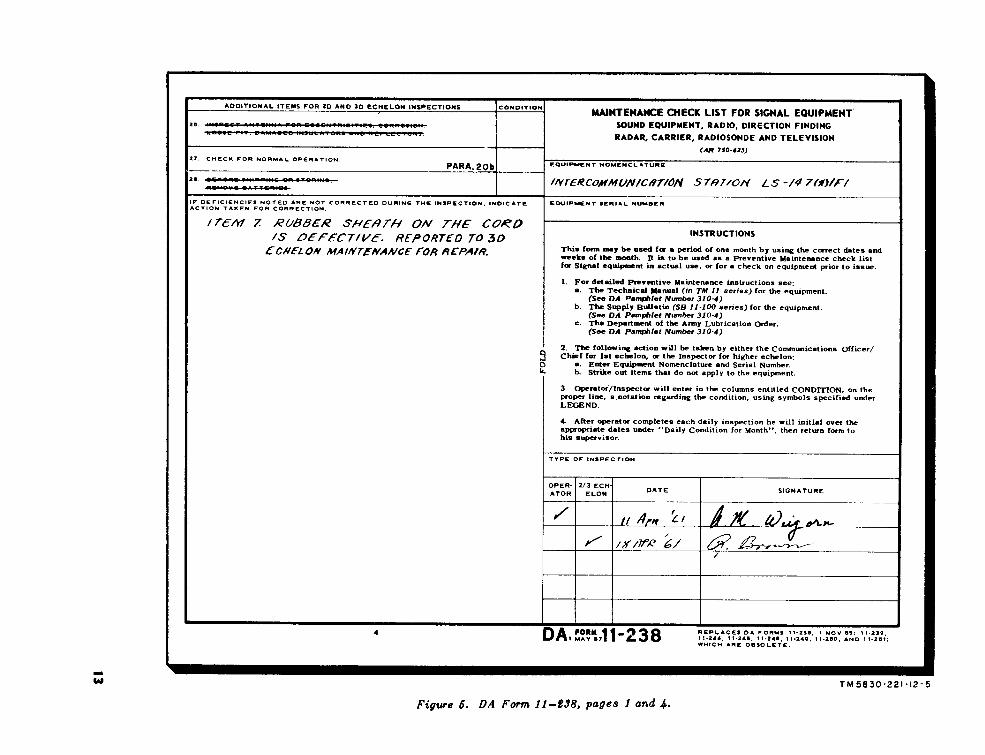
Figure 5
13 pages 1 and 4
TM
5830-221-12-5

Figure 6
pages 2 and 3
TM
5830-221-12-6
14

Section Il. ORGANIZATIONAL MAINTENANCE
18. Scope of Organizational Maintenance
The second echelon maintenance proce-dures on the LS-147(*)/FI consist of thefollowing:
a. Preventive maintenance (para 20).b. Visual inspection (para 21).c. Troubleshooting (para 22).d. Tube testing and replacement (para
23).e. Removal and replacement of pilot
lamp (para 24).
19. Tools and Test Equipment
The tools and test equipment requiredfor organizational maintenance are listedbelow:
a. Tool Equipment TE-41.b. Tool Equipment TE-113.c . Test Set , Electron Tube TV-7 /U.
20. Preventive Maintenance
a. Use of DA Form 11-238. I t e m s 1through 28 on DA Form 11-238 (fig. 5 and6) constitute the preventive maintenancechecklist to be used by organizationalmaintenance personnel. Items not appli-cable to the equipment are lined out in thefigures. References in the ITEM block offigures 5 and 6 are to paragraphs that con-tain additional information pertinent to theparticular item. Instructions for use of theform appear on page 1 of the form.
b. Items. The following information issupplementary to DA Form 11-238. Theitem numbers correspond to the ITEMnumbers on the form.
Warning: Turn the VOLUME control(LS-147A/FI and LS-147B/FI) or the OFF-SEND control (LS-147C/FI and LS-147D/FI) to the OFF position, and disconnect theline cord plug from the ac outlet beforeperforming items 15 and 19 of the follow-ing procedures.
Item Maintenance procedures
15 Check all tubes for proper seating in the tubesockets. Tube clamps are provided on theLS-147C/FI chassis for securing the tubesin the sockets (fig. 8).
19 Check the PRESS TO TALK switch for burneddirty, or open contacts.
27 Perform the checks as indicated in the equip-ment performance checklist (para 16) todetermine if the unit is operating properly.
21. Visual Inspection
Before operating the LS-147(*)/FI, in-spect it. This will save repair time andmay avoid further damage to the unit. Inaddition to the checks listed in paragraph16, inspect the following for obvious de-fects before proceeding to the trouble-shooting checklist (para 22).
a. Pilot lamp.b. Seating of tubes.
22. Troubleshooting Checklist
The chart in b below is provided to helplocalize troubles in the LS-147(*)/FI to adefective tube, or pilot lamp. Only thosecorrective measures that the organiza-tional maintenance man can perform aregiven. If the the measure indicated doesnot restore normal equipment perform-ance, troubleshooting is required at a fieldmaintenance level. Note on the repair tagwhat corrective measures were taken.
a. General. Before using the trouble-shooting checklist, examine the repair tagto determine whether the trouble has beensectionalized. If there has been no section-alization, perform the procedures outlinedin the equipment performance checklist(para 16).
b. Troubleshooting Chart. When per -forming the checks indicated in the chartbelow, refer to figures 7, 8, and 9.
Symptom Probable trouble Correction
Pilot lamp does not light when VOLUME Defective pilot Check pilot lamp. For replacement pro-control (LS-147A/FI and LS-147B/FI) lamp. cedures, refer to paragraph 24.and OFF-SEND control (LS-147C/FIand LS-147D/FI) are turned on.
15

Symptom
No transmission to distant station. Re-ception is normal. Pilot lamp lights.
Excessive hum transmitted to distantstation.
Probable trouble
Defective tubeV1, V2, orV3.
Defective tubeV1, V2, orV3.
Correction
Check tubes V1, V2, or V3 to see if filamentsglow or tube is cold. For testing and re-placement procedures, refer to paragraph23. If this does not clear trouble, trouble-shooting is required at field maintenancelevel.
Same as above.
23. Tube Testing and Replacement(fig. 7, 8, and 9)
If tube failure is suspected, use the ap-plicable procedure below to check thetubes:
Caution: Never rock or rotate a tubewhen removing it from a socket; carefullypull it straight out. Before replacing thetube in the socket, make certain that thetube pins are properly aligned with thetube socket.
a. Using Tube Tester. Remove and testone tube at a time. Discard a tube only ifits defect is obvious, such as an open fila-ment or a broken envelope, or if the tubetester shows the tube to be defective. Donot discard a tube that tests at or slightlybelow its minimum test limit; such a tubemay provide satisfactory performance fora long operational period. Put back theoriginal tube or install a new one beforetesting the next one.
b. Tube Substitution. Replace a sus-pected tube with a new tube. If the LS-147(*)/FI remains inoperative, remove thenew tube and replace the original tube.Repeat this procedure with each suspectedtube until the defective tube is discovered.
Note. Use the tube tester rather than the tubesubstitution method whenever possible.
24. Removal and Replacement of Pilot Lamp
To remove and replace the pilot lamp inthe LS-147A/FI and LS-147B/FI, use theprocedures in a below. To remove andreplace the pilot lamp in the LS-147C/FIand LS-147D/FI, use the procedures in bbelow.
a. LS-147A/FI and LS-147B/FI (fig. 7).(1) Remove the rear panel from the
cabinet by removing the retaining
16
(2)
(3)
(4)
(5)
(6)
(7)
(8)
(9)
screws and washers.Remove the knobs from the con-trols on the front panel by loosen-ing the knob-retaining screws. Onsome models, Allen-head screwsare used as knob-retaining screws.R e m o v e the chassis - retainingscrews and remove the rubber feetfrom the bottom of the cabinet.Remove the chassis from the cab-inet.Press in the pilot lamp, twist it1/4 turn counterclockwise, and re-move it from the holder.Obtain a new type No. 44 pilot lampand install it by aligning the pins onthe lamp base with the slots in thelamp socket. Push the lamp into thesocket and turn 1/4 turn clockwise.Replace the chassis in the cabinetand replace the rubber feet and thechassis-retaining screws.
Caution: Do not overtighten thechassis-retaining screws, becausethis will damage the rubber feet.Replace the rear cover plate withthe vent slots pointing outward anddownward. The rear cover plate ofthe LS-147A/FI, LS-147B/FI, andLS-147D/FI are prov ided withguides which fit into the top of theinside of the cabinet.Replace the front panel controlknobs on the shafts and tighten theknob-retaining screws. Do not pushthe knobs flush to the front panelwhen t ightening the reta in ingscrews, because this will cause theknob to rub on the front panel.
b. LS-147C/FI and LS-147D/FI (fig. 2and 3).
(1) Unscrew the pilot lamp counter-

clockwise. and remove it from itsholder on the front panel.
(2) Obtain a new type NE-45 pilot lampand install it in the lamp socket.
Figure 7. LS-147A/FI or LS-147B/FI, removed from cabinet, showing location of tubes, fuse, pilotlamp, and binding posts.
17
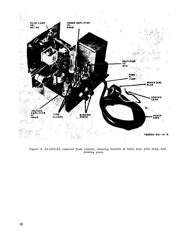
Figure 8. LS-147C/FI, removed from cabinet, showingbinding posts.
location of tubes, fuse, pilot lamp, and
18

Figure 9. LS-147D/FI, removed from cabinet, showing location of tubes, fuse, pilot lamp, andbinding posts.
19
CHAPTER 4
SHIPMENT AND LIMITED STORAGE AND DEMOLITION
TO PREVENT ENEMY USE
Section I. SHIPMENT AND LIMITED STORAGE
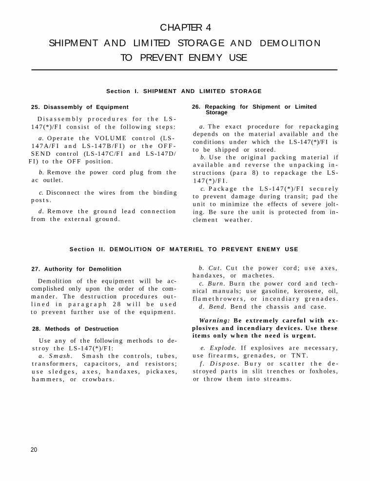
25. Disassembly of EquipmentStorage
Disassembly procedures for the LS-147(*)/FI consist of the following steps:
a. Operate the VOLUME control (LS-147A/FI and LS-147B/FI) or the OFF-SEND control (LS-147C/FI and LS-147D/
FI) to the OFF position.
b. Remove the power cord plug from theac outlet.
c. Disconnect the wires from the bindingposts.
d. Remove the ground lead connectionfrom the external ground.
26. Repacking for Shipment or Limited
a. The exact procedure for repackagingdepends on the material available and theconditions under which the LS-147(*)/FI isto be shipped or stored.
b. Use the original packing material ifavailable and reverse the unpacking in-structions (para 8) to repackage the LS-147(*)/FI.
c. Package the LS-147(*)/FI securelyto prevent damage during transit; pad theunit to minimize the effects of severe jolt-ing. Be sure the unit is protected from in-clement weather.
Sect ion I I . DEMOLITION OF MATERIEL TO PREVENT ENEMY USE
27. Authority for Demolition
Demolition of the equipment will be ac-complished only upon the order of the com-mander. The destruction procedures out-l i n e d i n p a r a g r a p h 2 8 w i l l b e u s e dto prevent further use of the equipment.
28. Methods of Destruction
Use any of the following methods to de-stroy the LS-147(*)/FI:
a. Smash. Smash the controls, tubes,transformers, capacitors, and resistors;use s ledges , axes , handaxes, pickaxes,hammers, or crowbars.
b. Cut. Cut the power cord; use axes,handaxes, or machetes.
c. Burn. Burn the power cord and tech-nical manuals; use gasoline, kerosene, oil,f lamethrowers, or incendiary grenades.
d. Bend. Bend the chassis and case.
Warning: Be extremely careful with ex-plosives and incendiary devices. Use theseitems only when the need is urgent.
e. Explode. If explosives are necessary,use firearms, grenades, or TNT.
f . Dispose . Bury or scat ter the de -stroyed parts in slit trenches or foxholes,or throw them into streams.
20

APPENDIX I
REFERENCES
Following is a list of references applicable and available to the operator of Intercom-munication Stations LS-147A/FI, LS-147B/FI, LS-147C/FI, and LS-147D/FI.
TM 11-5830-221-20P Organizational Maintenance Repair Parts and Special ToolsList, Intercommunication Stations LS-147A/FI, LS-147B/FI, LS-147C/FI, and LS-147D/FI.
TM 11-6625-203-12 Operation and Organizational Maintenance: Multimeter AN/URM-105, Including Multimeter ME-77/U.
TM 11-6625-274-12 Operator’s and Organizational Maintenance Manual: TestSets, Electron Tube TV-7/U, TV-7A/U, TV-7B/U, andTV-7D/U.
21

APPENDIX IIMAINTENANCE ALLOCATION
Section I. INTRODUCTION
1. General
a. This appendix assigns maintenancefunctions and repair operations to be per-formed by the lowest appropriate main- ( f )tenance echelon.
b. Columns in the maintenance alloca-tions chart are as follows:
(1)
(2)
Part or component. This co lumnshows only the nomenclature orstandard item name. Additionaldescriptive data are included onlywhere clarification is necessary to (3)identify the part. Components andparts and subassemblies are inalphabetical sequence with theircomponents listed alphabeticallyimmediately below the assemblylisting.
Maintenance function. This column
(a)
(b)
(c)
(d)
(e)
22
indicates the various maintenancefunctions allocated to the echeloncapable of performing the opera-tion. These are as follows:
(4)
equipment, and skills available,to include welding, grinding, riv-eting, straightening, adjusting,etc .Rebuild. T O restore to a condi-tion comparable to new by dis-assembling the item to determinethe condition of its componentparts and reassembling it usingserviceable, rebuilt, or new as-semblies, subassembl ies , andparts.
1st, 2d, 3d, 4th, and 5th echelon.The symbol X indicates the echelonresponsible for performing thatparticular maintenance operation,but does not necessarily indicatethat repair parts will be stockedat that level. Echelons higher thanthe echelon marked by X are au-thorized to perform the indicatedoperation.
Tools required. This column indi-cates codes assigned to each indi-
Service. To clean, to preserve,and to replenish fuel and lubri-cants.Inspect. To verify serviceabilityand to detect incipient electricalor mechanical failure by scru-tiny.Test. To ver i fy serv iceabi l i ty
vidual tool equipment, test equip-ment, and maintenance equipmentreferenced. The grouping of codesin this column indicates the tool,test, and maintenance equipmentrequired to perform the mainte-nance function.
and to detect inc-ipient electrical c . Columns in the allocation of tools for
or mechanical failure by use of maintenance functions are as follows:
special equipment such as gages, (1)meters, etc.Replace. To substitute service-able assemblies, subassemblies,and parts for unserviceable com-ponents. (2)Repair. To restore to a service-able condition by replacing un-serviceable parts or by any other (3)action required utilizing tools.
Tools required for maintenancefunctions. This column lists tools,test, and maintenance equipmentrequired to perform the mainte-nance functions.1st, 2d, 3d, 4th, and 5th echelon. Adagger (†) symbol indicates theechelon allotted to the facility.Tool code. This column lists thetool code assigned.

2. Maintenance by Using Organizations ized to the organization operating thisequipment.
When this equipment is used by sig- 3. Mounting Hardwarenal service organizations organic totheater headquarters or communication The basic entries of this maintenancezones to provide theater communications, allocation chart do not include mountingthose maintenance fuctions allocated up to hardware such as: screws, nuts, bolts,and including fourth echelon are author- washers, brackets, clamps, etc.
23

Section II
24
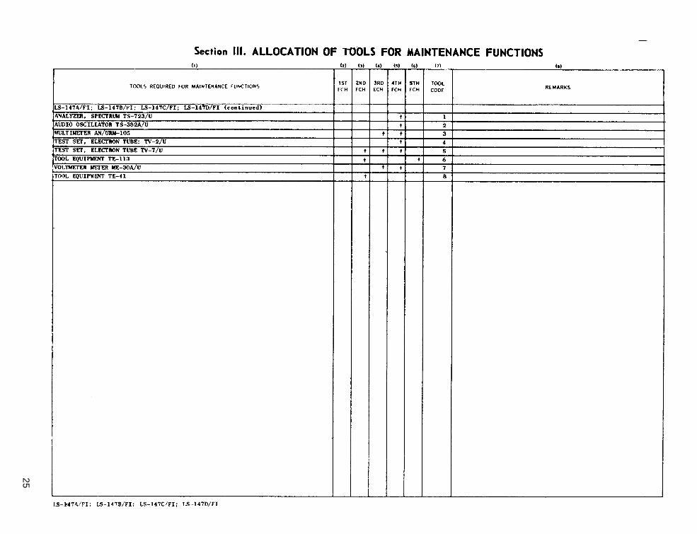
Section III
25

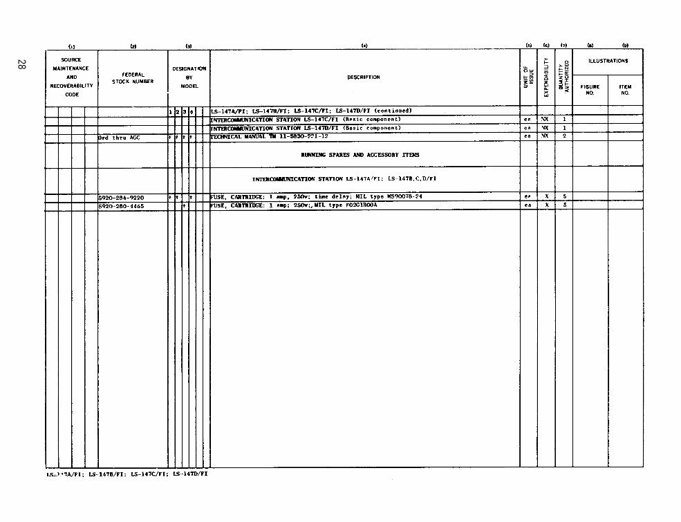
APPENDIX IIIBASIC ISSUE ITEMS LIST
Section I. INTRODUCTION
1. General
This appendix lists items supplied forinitial operation and for running spares.The list includes tools, accessories, parts,and material issued as part of the majorend item. The list includes all items au-thorized for basic operator maintenance ofthe equipment. End items of equipment areissued on the basis of allowances pres-cribed in equipment authorization tablesand other documents that are a basis forrequisitioning.
2. Columns
a. Source, Maintenance, and Recover-ability Code. Not used.
b. Federal Stock Number. This columnlists the n-digit Federal stock number.
c. Designation by Model. The dagger(†) indicates the model in which the partis used.
d. Description. Nomenclature or the
standard item name and brief identifyingdata for each item are listed in this column.When requisitioning, enter the nomencla-ture and description..
e. Unit of Issue. The unit of issue is thesupply term by which the individual itemis counted for procurement, storage, req-uisitioning, allowances, and issue pur-poses.
f. Expendability. Expendable items areindicated by the letter X; nonexpendableitems are indicated by NX.
g. Quantity Authorized. Under “ItemsComprising an Operable Equipment”, thecolumn lists the quantity of items suppliedfor the initial operation of the equipment.Under “Running Spares and AccessoryItems”, the quantities listed are thoseissue’d initially with the equipment as spareparts. The quantities are authorized to bekept on hand by the operator for mainte-nance of the equipment.
h. Illustrations. Not used.
26

Section II
27
28

By Order of the Secretary of the Army:
Official:
R. V. LEE,Major General, United States
The Adjutant General.
Distribution:
Active Army:
G. H. DECKER,General, United States Army,
Chief of Staff.
Army,
To be distributed in accordance with DA Form 12-7 requirements for TM 11 Series (Unclas) plusthe following:
DASA (5) 11-97 (2)USASA (2) 11-98 (2)CNGB (1) 11-117 (2)Tech Stf, DA (1) 11-155 (2)
except CSigO (18)ARADCOM (2)ARADCOM Rgn (2)MDW (1)Seventh US Army (2)EUSA (2)Units org under fol TOE:
9-47 (2)9-87 (2)9-227 (2)9-377 (2)9 -500 (AA-AC) (2 )11-5 (2)11-7 (2)11-16 (2)11-57 (2)11-96 (2)
11-500 (AA-AE) (RM-RT) (4)11-555 (2)11-557 (2)11-587 (2)11-592 (2)11-5’37 (2)44-435 (2)44-436 (2)44-437 (2)44-446 (2)44-535 (2)44-636 (2)44-537 (2)44-544 (2)44-546 (2)44-548 (2)
NG: State AG (3); Units-Same as Active Army except allowance is one copyUSAR: None.For explanation of abbreviations used, see AR 320-50.
to each unit.
29


This fine document...
Was brought to you by me:
Liberated Manuals -- free army and government manuals
Why do I do it? I am tired of sleazy CD-ROM sellers, who take publicly available information, slap “watermarks” and other junk on it, and sell it. Those masters of search engine manipulation make sure that their sites that sell free information, come up first in search engines. They did not create it... They did not even scan it... Why should they get your money? Why are not letting you give those free manuals to your friends?
I am setting this document FREE. This document was made by the US Government and is NOT protected by Copyright. Feel free to share, republish, sell and so on.
I am not asking you for donations, fees or handouts. If you can, please provide a link to liberatedmanuals.com, so that free manuals come up first in search engines:
<A HREF=http://www.liberatedmanuals.com/>Free Military and Government Manuals</A>
– SincerelyIgor Chudovhttp://igor.chudov.com/
– Chicago Machinery Movers


![OPERATOR’S MANUAL [ENGLISH]OPERATOR’S MANUAL INCLUDING: OPERATION, INSTRUCTION, INSTALLATION, MAINTENANCE AND PARTSBOOK ... Installation, adjustment repair and maintenance of this](https://static.fdocuments.us/doc/165x107/5ebe4fee280d8f0d1e29c2f7/operatoras-manual-english-operatoras-manual-including-operation-instruction.jpg)


