Operator’s Manualthis operator’s manual. General Operation & Repair 1. Never allow the drill to...
34
! Read the operator’s manual entirely. When you see this symbol, the subsequent in- structions and warnings are serious - follow without exception. Your life and the lives of others depend on it! Cover illustration may show optional equipment not supplied with standard unit. © Copyright 1999 Printed www.greatplainsmfg.com Manufacturing, Inc. 150-082M-A 13844 Operator’s Manual EWNT7 and EWNT10 End Wheel No Till Drill Model Serial No. EWNT7 1523Q - 1630Q EWNT10 4142U - 4568U 4/12/2005
Transcript of Operator’s Manualthis operator’s manual. General Operation & Repair 1. Never allow the drill to...
! Read the operator’s manual entirely. When you see this symbol, the subsequent in-structions and warnings are serious - follow without exception. Your life and the lives ofothers depend on it!
Cover illustration may show optional equipment not supplied with standard unit.
© Copyright 1999 Printed
www.greatplainsmfg.comManufacturing, Inc.
150-082M-A
13844
Operator’s ManualEWNT7 and EWNT10
End Wheel No Till DrillModel Serial No.
EWNT7 1523Q - 1630Q
EWNT10 4142U - 4568U
4/12/2005
EWNT7 and EWNT10 End Wheel No Till Drill 150-082M-A 4/25/06Great Plains Mfg., Inc.
General Information
Great Plains Manufacturing, Inc. provides this publica-tion “as is” without warranty of any kind, either ex-pressed or implied. While every precaution has beentaken in the preparation of this manual, Great PlainsManufacturing, Inc. assumes no responsibility for errors oromissions. Neither is any liability assumed for damagesresulting from the use of the information contained here-in. Great Plains Manufacturing, Inc. reserves the right torevise and improve its products as it sees fit. This publi-
cation describes the state of this product at the time of itspublication, and may not reflect the product in the future.
Printed in the United States of America.
For your convenience, record your Serial Number, Mod-el Number and the Date Purchased in the spaces pro-vided below. Have this information available whencalling your Great Plains Authorized Dealer.
Important Notice
This Operator’s Manual applies to the7’ & 10’ End Wheel No-Till
Owner’s InformationName: _____________________________________
Address ____________________________________
City________________State ____ Zip ___________
Phone_______________________
Name of Dealership ___________________________
Dealer’s Name _______________________________
Address ____________________________________
City________________State ____ Zip ___________
Phone_______________________
Serial Number ________________
Model Number ________________
Date Purchased _______________

-14/25/06 Great Plains Mfg., Inc. EWNT7 and EWNT10 End Wheel No Till Drill 150-082M-A
Table of Contents
Introduction. . . . . . . . . . . . . . . . . . . . . . . . . . . . . . . . . . . . 2Using this Manual . . . . . . . . . . . . . . . . . . . . . . . . . . . . . . . 2Section 1 Safety Rules . . . . . . . . . . . . . . . . . . . . . . . . . . . 3
General Operation & Repair . . . . . . . . . . . . . . . . . . . . 3Transporting. . . . . . . . . . . . . . . . . . . . . . . . . . . . . . . . . 3Tire Handling & Repair . . . . . . . . . . . . . . . . . . . . . . . . 3Safety Decals. . . . . . . . . . . . . . . . . . . . . . . . . . . . . . . . 3
Section 2 Assembly Instructions & Set-Up . . . . . . . . . . 6Tire Inflation Chart . . . . . . . . . . . . . . . . . . . . . . . . . . . . 6Torque Values Chart for Common Bolt Sizes . . . . . . . 6Pre-Assembly Checklist . . . . . . . . . . . . . . . . . . . . . . . . 7Tractor Requirements . . . . . . . . . . . . . . . . . . . . . . . . . 8Tractor Drawbar Hook-Up . . . . . . . . . . . . . . . . . . . . . . 8Tractor Drawbar Hook-Up For Ball Swivel Hitch . . . . . . 8Tractor Hydraulic Hook-Up. . . . . . . . . . . . . . . . . . . . . . 9Bleeding the Hydraulic Lifting System . . . . . . . . . . . . . 9
Section 3 Basic Operation . . . . . . . . . . . . . . . . . . . . . . . 10Operating the Lifting Hydraulic System . . . . . . . . . . . 10Transporting. . . . . . . . . . . . . . . . . . . . . . . . . . . . . . . . 10Operating Transport Lock . . . . . . . . . . . . . . . . . . . . . 10Lock Out Hubs . . . . . . . . . . . . . . . . . . . . . . . . . . . . . . 10
Section 4 Adjustments . . . . . . . . . . . . . . . . . . . . . . . . . . 11Drive System Clutch . . . . . . . . . . . . . . . . . . . . . . . . . 11Drive Train Operation . . . . . . . . . . . . . . . . . . . . . . . . . 11Seeding Rate . . . . . . . . . . . . . . . . . . . . . . . . . . . . . . . 12Change Drive Sprockets . . . . . . . . . . . . . . . . . . . . . . 12Set Seed-Rate Handle. . . . . . . . . . . . . . . . . . . . . . . . 12Position Seed-Cup Doors . . . . . . . . . . . . . . . . . . . . . 12Check Seeding Rate . . . . . . . . . . . . . . . . . . . . . . . . . 13Seed Rate Charts . . . . . . . . . . . . . . . . . . . . . . . . . . . 14Fertilizer Drive . . . . . . . . . . . . . . . . . . . . . . . . . . . . . . 19
Fertilizer Rate . . . . . . . . . . . . . . . . . . . . . . . . . . . . . . . 197’ & 10’ Fertilizer Application Chart . . . . . . . . . . . . . . . 19Native Grass Drive . . . . . . . . . . . . . . . . . . . . . . . . . . . 20Native Grass Rate . . . . . . . . . . . . . . . . . . . . . . . . . . . . 20Native Grass Seeding Adjustments. . . . . . . . . . . . . . . 20Native Grass Seed Rate Charts & Sprockets . . . . . . . 21Planting Depth Adjustments . . . . . . . . . . . . . . . . . . . . 22Coulter Hydraulic Depth Control . . . . . . . . . . . . . . . . . 22Down Pressure Requirements . . . . . . . . . . . . . . . . . . 22Individual Opener & Coulter . . . . . . . . . . . . . . . . . . . . 23Disk Opener Spring Pressure Setting . . . . . . . . . . . . . 23Individual Opener Height. . . . . . . . . . . . . . . . . . . . . . . 23Opener Press Wheel Depth . . . . . . . . . . . . . . . . . . . . 24Press Wheel Angle . . . . . . . . . . . . . . . . . . . . . . . . . . . 24
Section 5 Field Operations . . . . . . . . . . . . . . . . . . . . . . . 25Drill Preparations. . . . . . . . . . . . . . . . . . . . . . . . . . . . . 25Operating Checklist . . . . . . . . . . . . . . . . . . . . . . . . . . . 25
Section 6 Maintenance & Lubrication. . . . . . . . . . . . . . . 26Maintenance . . . . . . . . . . . . . . . . . . . . . . . . . . . . . . . . 26Fertilizer Unit . . . . . . . . . . . . . . . . . . . . . . . . . . . . . . . . 26Storage . . . . . . . . . . . . . . . . . . . . . . . . . . . . . . . . . . . . 26Lubrication. . . . . . . . . . . . . . . . . . . . . . . . . . . . . . . . . . 26
Section 7 Troubleshooting . . . . . . . . . . . . . . . . . . . . . . . 29Section 8 Specifications & Warranty . . . . . . . . . . . . . . . 31

EWNT7 and EWNT10 End Wheel No Till Drill 150-082M-A 4/25/062 Great Plains Mfg., Inc.
Using this Manual
This manual has been prepared to instruct you in thesafe and efficient operation of your End Wheel No-Till.Read and follow all instructions and safety precautionscarefully.
The parts on your End Wheel No-Till have been special-ly designed and should only be replaced with genuineGreat Plains parts. Therefore, should your End WheelNo-Till require replacement parts go to your GreatPlains Dealer.
The right hand and left hand as used throughout thismanual is determined by facing in the direction the ma-chine will travel when in use unless otherwise stated.
Serial NumberThe serial number plate is located on the front right sideof the frame. It is suggested that the serial number andpurchase date also be recorded for your convenience inthe space provided on the checklist page at the begin-ning of this manual.
The serial number provides important information aboutyour drill and may be required to obtain the correct re-placement part. Always use the serial number and mod-el number when sending correspondence or whenordering parts from your Great Plains dealer.
The SAFETY ALERT SYMBOL indicates that there is apotential hazard to personal safety involved and extrasafety precautions must be taken. When you see this
!
symbol, be alert and carefully read the message that fol-lows it. In addition to design and configuration of equip-ment; hazard control and accident prevention aredependent upon the awareness, concern, prudence andproper training of personnel involved in the operation,transport, maintenance and storage of equipment.
Watch for the following safety notations throughout youroperator’s manual:
! DANGER!Indicates an imminently hazardous situation which, if notavoided, will result in death or serious injury. This signalword is limited to the most extreme situations.
! WARNING!Indicates a potentially hazardous situation which, if notavoided, could result in death or serious injury.
! CAUTION!Indicates a potentially hazardous situation which, if notavoided, may result in minor or moderate injury. It mayalso be used to alert against unsafe practices.
NOTE: Indicates a special point of information whichrequires your attention.
For your safety and to help in developing a better under-standing of your equipment, read this manual. Readingthese sections not only provides valuable training but
also familiarizes you with helpful information and its lo-cation. After reviewing your manual store it in a dry, eas-ily accessible location for future reference.
Using this Manual
Introduction

-34/25/06 Great Plains Mfg., Inc.
Section 1 Safety Rules
EWNT7 and EWNT10 End Wheel No Till Drill 150-082M-A
Most accidents are the result of negligence and care-lessness, usually caused by failure of the operator to fol-low simple but necessary safety precautions. Thefollowing safety precautions are suggested to help pre-vent such accidents. The safe operation of any machin-ery is a big concern to consumers andmanufacturers.Your End Wheel No-Till has been de-signed with many built-in safety features. However, noone should operate this product before carefully readingthis operator’s manual.
General Operation & Repair1. Never allow the drill to be operated by anyone who is un-
familiar with the operation of all functions of the unit. Alloperators should read and thoroughly understand the in-structions given in this manual prior to moving the unit.
2. Make sure safety rules are understood before operatingmachinery or tractor.
3. Never permit any persons other than the operator to rideon the tractor.
4. Never permit any persons to ride on or stand near thedrill while it is in operation.
5. Regulate your speed to the field conditions, maintainingcomplete control at all times.
6. After repairing or adjusting, make sure all tools andparts are removed from the implement before attemptingto operate it.
7. Do not grease or oil machine while it is in operation.
8. Loose fitting clothing should not be worn as it may catchin moving parts.
9. Never dismount from a moving tractor.
10. Do not leave the tractor or the implement unattendedwith the engine running.
11. Do not stand between the tractor and the implement dur-ing hitching.
12. Detach and store implements in an area where childrennormally do not play. Stabilize implements by using suit-able supports and block wheels.
13. If a hydraulic leak develops, correct it immediately. Es-caping hydraulic oil can have extremely high pressure. Astream of high pressure oil may easily penetrate the skin.It is imperative that the connections are tight and that alllines and pipes are in good condition. If an injury iscaused by the escaping hydraulic fluid, see doctor atonce!
14. Use a piece of cardboard or wood to detect leaks of hy-draulic oil under pressure.
15. Be sure to relieve all hydraulic pressure before disconnec-tion any lines or pipes between the implement and the trac-tor hydraulic system. Keep all guards and shields in place.
Transporting1. Use good judgement when transporting tractor and im-
plements on the highway. Always maintain complete con-trol of the machine.
2. Limit transport speed to 20 mph. Transport only with afarm tractor of sufficient size and horse power. See“Tractor Requirements” Section 2,page 8.
3. Always make sure flashing safety lights, “Slow MovingVehicle” emblem, and reflectors are in place and visibleprior to transporting the machine on public roads.
4. Know your state and local laws concerning highwaysafety and regulations. Comply with these laws whentransporting machinery.
5. Use warning flags or approved warning lights at nightand during other periods of poor visibility. Do your bestto prevent highway accidents.
Tire Handling & Repair1. Tire changing can be dangerous and should be pre-
formed by trained personnel using the correct tools andequipment.
2. Do not re-inflate a tire that has been run flat or seriouslyunder inflated. Have it checked by qualified personnel.
3. When removing and installing wheels, use wheel han-dling equipment adequate for the weight involved.
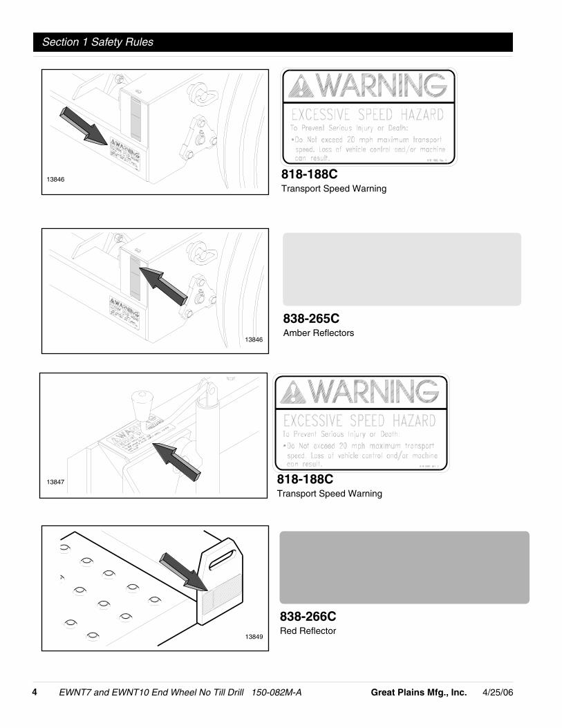
Safety Decals1. Your End Wheel No-Till comes equipped with all safety
decals in place. They were designed to help you safelyoperate your drill. Read and follow their directions.
2. Keep safety decals clean and legible.
3. Replace all damaged or missing safety decals. To ordernew safety decals go to your Great Plains dealer and re-fer to the parts section for safety decal package part num-ber.
4. Replace these decals whenever they become worn or un-readable. To install new safety decals:
a. Clean the area the decal is to be placed
b. Peel backing from the decal. Press firmly on to sur-face being careful not to cause air bubbles under thedecal.
Section 1 Safety Rules !
EWNT7 and EWNT10 End Wheel No Till Drill 150-082M-A 4/25/064 Great Plains Mfg., Inc.
Section 1 Safety Rules
818-188CTransport Speed Warning
838-265CAmber Reflectors
818-188CTransport Speed Warning
13846
13846
13847
838-266CRed Reflector
13849

-54/25/06 Great Plains Mfg., Inc.
Section 1 Safety Rules
EWNT7 and EWNT10 End Wheel No Till Drill 150-082M-A
818-003CSlow Moving Vehicle Emblem13848

EWNT7 and EWNT10 End Wheel No Till Drill 150-082M-A 4/25/066 Great Plains Mfg., Inc.
Section 2 Assembly Instructions & Set-Up
Tire Inflation ChartTire Size Inflation PSI
7.50 x 20" 4-Ply Drill Rib 28
9.0 x 22.5 10-Ply Highway Service 70 70
9.0 x 24" 8-Ply Rib Implement 40
9.5L x 15" 6-Ply Rib Implement 32
9.5L x 15" 8-Ply Rib Implement 44
9.5L x 15" 12-Ply Rib Implement 60
Section 2 Assembly Instructions & Set-Up
Tire Size Inflation PSI
11L x 15" 6-Ply Rib Implement 28
11L x 15" 12-Ply Rib Implement 52
12.5L x 15" 8-Ply Rib Implement 36
12.5L x 15" 10-Ply Rib Implement 44
16.5L x 16.1" 10-Ply Rib Implement 36
41 x 15" x 18 - 22-Ply Rib Implement 44
Torque Values Chart for Common Bolt Sizes
in-tpi1 N · m2 ft-lb3 N · m ft-lb N · m ft-lb mm x pitch4 N · m ft-lb N · m ft-lb N · m ft-lb
1/4" - 20 7.4 5.6 11 8 16 12 M 5 X 0.8 4 3 6 5 9 7
1/4" - 28 8.5 6 13 10 18 14 M 6 X 1 7 5 11 8 15 11
5/16 - 18 15 11 24 17 33 25 M 8 X 1.25 17 12 26 19 36 27
5/16" - 24 17 13 26 19 37 27 M 8 X 1 18 13 28 21 39 29
3/8" - 16 27 20 42 31 59 44 M10 X 1.5 33 24 52 39 72 53
3/8" - 24 31 22 47 35 67 49 M10 X 0.75 39 29 61 45 85 62
7/16" - 14 43 32 67 49 95 70 M12 X 1.75 58 42 91 67 125 93
7/16" - 20 49 36 75 55 105 78 M12 X 1.5 60 44 95 70 130 97
1/2" - 13 66 49 105 76 145 105 M12 X 1 90 66 105 77 145 105
1/2" - 20 75 55 115 85 165 120 M14 X 2 92 68 145 105 200 150
9/16" - 12 95 70 150 110 210 155 M14 X 1.5 99 73 155 115 215 160
9/16" - 18 105 79 165 120 235 170 M16 X 2 145 105 225 165 315 230
5/8" - 11 130 97 205 150 285 210 M16 X 1.5 155 115 240 180 335 245
5/8" - 18 150 110 230 170 325 240 M18 X 2.5 195 145 310 230 405 300
3/4" - 10 235 170 360 265 510 375 M18 X 1.5 220 165 350 260 485 355
3/4" - 16 260 190 405 295 570 420 M20 X 2.5 280 205 440 325 610 450
7/8" - 9 225 165 585 430 820 605 M20 X 1.5 310 230 650 480 900 665
7/8" - 14 250 185 640 475 905 670 M24 X 3 480 355 760 560 1050 780
1" - 8 340 250 875 645 1230 910 M24 X 2 525 390 830 610 1150 845
1" - 12 370 275 955 705 1350 995 M30 X 3.5 960 705 1510 1120 2100 1550
1-1/8" - 7 480 355 1080 795 1750 1290 M30 X 2 1060 785 1680 1240 2320 1710
1 1/8" - 12 540 395 1210 890 1960 1440 M36 X 3.5 1730 1270 2650 1950 3660 2700
1 1/4" - 7 680 500 1520 1120 2460 1820 M36 X 2 1880 1380 2960 2190 4100 3220
1 1/4" - 12 750 555 1680 1240 2730 2010
1 3/8" - 6 890 655 1990 1470 3230 2380 1 in-tpi = nominal thread diameter in inches–threads per inch
1 3/8" - 12 1010 745 2270 1670 3680 2710 2 N· m = newton-meters
1 1/2" - 6 1180 870 2640 1950 4290 3160 3 ft-lb= foot pounds
1 1/2" - 12 1330 980 2970 2190 4820 3560 4 mm x pitch = nominal thread dia. in millimeters x thread pitch
5.8 8.8 10.9
Class 5.8 Class 8.8 Class 10.9
Bolt Head Identification
Bolt Size(Metric)Grade 2 Grade 5 Grade 8
Bolt Head Identification
Bolt Size(Inches)
-74/25/06 Great Plains Mfg., Inc.
Section 2 Assembly Instructions & Set-Up
EWNT7 and EWNT10 End Wheel No Till Drill 150-082M-A
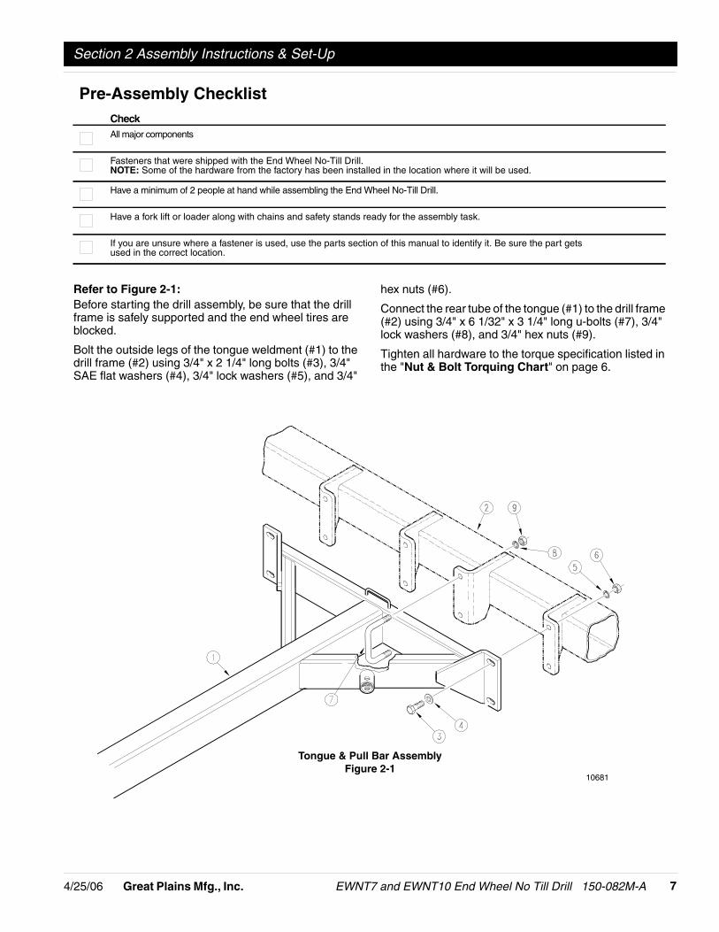
Refer to Figure 2-1:Before starting the drill assembly, be sure that the drillframe is safely supported and the end wheel tires areblocked.
Bolt the outside legs of the tongue weldment (#1) to thedrill frame (#2) using 3/4" x 2 1/4" long bolts (#3), 3/4"SAE flat washers (#4), 3/4" lock washers (#5), and 3/4"
hex nuts (#6).
Connect the rear tube of the tongue (#1) to the drill frame(#2) using 3/4" x 6 1/32" x 3 1/4" long u-bolts (#7), 3/4"lock washers (#8), and 3/4" hex nuts (#9).
Tighten all hardware to the torque specification listed inthe "Nut & Bolt Torquing Chart" on page 6.
Pre-Assembly ChecklistCheckAll major components
Fasteners that were shipped with the End Wheel No-Till Drill.NOTE: Some of the hardware from the factory has been installed in the location where it will be used.
Have a minimum of 2 people at hand while assembling the End Wheel No-Till Drill.
Have a fork lift or loader along with chains and safety stands ready for the assembly task.
If you are unsure where a fastener is used, use the parts section of this manual to identify it. Be sure the part getsused in the correct location.
Tongue & Pull Bar AssemblyFigure 2-1
10681

EWNT7 and EWNT10 End Wheel No Till Drill 150-082M-A 4/25/068 Great Plains Mfg., Inc.
Section 2 Assembly Instructions & Set-Up
Tractor RequirementsTo operate your Great Plains End Wheel No-Till Drill inmost field conditions, a tractor of adequate size shouldbe used. For 7’ drills, a 55 horsepower tractor is re-quired. For 10’ drills, a 75 horsepower tractor is required.
7’ and 10’ drills require one set of remote outlets.
Tractor Drawbar Hook-UpRefer to Figure 2-2 & Figure 2-3:The Great Plains No-Till Drill is equipped with either asingle strap, Figure 2-2, clevis style hitch, Figure 2-3, ora ball swivel hitch, Figure 2-5. For proper field operation,the tongue of the drill should run level, parallel to theground in field position.
Tractor DrawbarHook-Up For Ball Swivel HitchRefer to Figure 2-4:Place a spacer tube (#9) above and below the ball swiv-el. Bolt the ball swivel {top hitch weldment} (#1) andspacer tubes (#9) to the drill clevis hitch with a 1" x 5"long bolt (#10), 1" USS flat washer (#11), and 1" nylocknut (#12).
Back the tractor to the drill hitch. Using the screw jack,adjust the drill tongue up or down to center the drawbarbelow the upper hitch plate (#1). Place hitch weldment(#1) on top of the tractor drawbar, aligning the rear holein the hitch weldment with the large hole in the drawbar.Place the lower hitch plate (#2) under the drawbar andattach to the hitch weldment (#1) with {2} 5/8" x 4" longbolts (#3), 5/8" flat washers (#4), 5/8" nylock nuts (#5).Bolt the top hitch weldment (#1) through the hole in thedrawbar to the lower hitch plate (#2) with a 1" x 5 1/2"long bolt (#6), 1" USS flat washer (#7), and 1" nylock nut(#8).
Clevis Style HitchSingle Strap Hitch
10127
Figure 2-2 Figure 2-3 Refer to Figure 2-5:1. With the drill lowers and in the field position, adjust
the tongue jack to level the tongue.
2. Back the tractor draw bar up to the drill hitch to de-termine the amount of adjustment required.
Refer to Figure 2-6:3. The mounting holes in the hitch have been offset so
the hitch can be turned over and bolted on in threedifferent hitch positions, giving you six different hitchheights.
11549
Ball Swivel HitchFigure 2-4
10150Jack In Vertical Position
Figure 2-5

-94/25/06 Great Plains Mfg., Inc.
Section 2 Assembly Instructions & Set-Up
EWNT7 and EWNT10 End Wheel No Till Drill 150-082M-A
4. Connect the hitch to the tractor using a pin of ade-quate strength (minimum 1" diameter).
Refer to Figure 2-7:5. Unpin the tongue jack, and pin it on top of the
tongue.
Your drill comes equipped with a hitch safety chain. Thesafety chain should be securely attached to the drill hitchand the tractor drawbar whenever towing or planting.
Tractor Hydraulic Hook-UpRoute the lift hydraulic hoses along the tongue andthrough the hose loop on the front of the tongue. Con-nect the hoses to the tractor remote outlets.
! CAUTION!Escaping fluid under pressure can have sufficient force to pen-etrate the skin. Check all hydraulic lines and hoses before ap-plying pressure. Fluid escaping from a very small hole can bealmost invisible. Use paper or cardboard, not body parts, tocheck for suspected leaks. If injured, seek medical assistancefrom a doctor that is familiar with this of injury. Foreign fluidsin the tissue must be surgically removed within a few hours organgrene will result.
10123
Hitch Height AdjustmentFigure 2-6
11833Jack In Transport Position
Figure 2-7
NOTE: Make sure the hitch is securely bolted to thedrill tongue.
Bleeding theHydraulic Lifting SystemThe implement lifting system is equipped with rephasingtype hydraulic cylinders that require a special procedurefor bleeding air from the hydraulic circuits. Read and fol-low the procedure carefully. The rephasing type cylin-ders will not function properly with air in the hydrauliccircuit. Bleeding the system may have been done duringinitial set up of the drill.
1. Jack up and support the front member of the drill ata point close to each end wheel. If the end wheel cyl-inders have previously been engaged, they may beused to assist in raising the frame.
2. With the frame blocked and supported, unpin thecylinders from the drill frame and turn the cylindersupside down and wire or otherwise safely supportthe rod end port higher than the base end port.
3. With the tractor engine at an idle speed, hold the re-mote lever on to put fluid into the lifting circuit. Whenthe cylinders have completely extended, hold the re-mote lever on for one minute.
4. Retract the cylinders. Extend the cylinders againand hold the remote lever on for one more minute.Repeat this step two more times to completely bleedthe system.
5. Repin the cylinders to the drill frame, rod end to thewheel arm. If air is trapped in either cylinder, the af-fected cylinder will have a spongy, erratic movementand the drill will not raise evenly. Refill the tractor hy-draulic fluid reservoir to its proper level.
IMPORTANT: When using sealant on pipe threads thefriction between the threads is reduced; therefore, becertain not to over tighten causing damage to the cylin-der port or fitting.
NOTE: Check the hydraulic fluid in the tractor reser-voir and fill to the proper level. Add fluid to the sys-tem as needed. A low reservoir level may draw airback into the system, causing jerky or uneven cylin-der movements. The drill system capacity is approx-imately 1 gallon.
NOTE: After the drill is raised, a slight settling will oc-cur due to the action of the rephasing cylinders.
EWNT7 and EWNT10 End Wheel No Till Drill 150-082M-A 4/25/0610 Great Plains Mfg., Inc.
Section 3 Basic Operation
Operating theLifting Hydraulic SystemThe lift cylinders may after a period of time get out oftime or phase. The effects of this can be seen when oneside of the drill is running too low or too high because itslift cylinder is either overextended or overretracted com-pared to the other lift cylinder. To rephase the cylinders,raise the drill completely up and hold the tractor hydrau-lic lever on for a few seconds to give the cylinders time torephase. This should be done each time the drill israised out of the ground. Momentarily reversing the hy-draulic lever immediately after rephasing to allow the cyl-inders to retract about 1/2" will help in maintaining a leveldrill.
TransportingOperating Transport LockRefer to Figure 3-1:When transporting your drill, you should always lockyour drill in the raised position. Fully extend the lift cylin-ders to raise the drill for transporting. Remove the lockpins from the storage position, Figure 3-1. {One on eachside of the drill frame.}
Refer to Figure 3-2:Place the lock pin through the frame channel as shownin Figure 3-2. Before lowering the drill, you must first ex-tend the lift cylinders completely and move the lock pinsto their storage position.
Lock Out HubsBefore transporting the drill, you should always checkthe following items:
1. Make sure that drill is securely attached to the drawbar of the tractor and that the hitch safety chain hasbeen securely attached.
2. Check to see that the transport tires have the properinflation as noted on page 6.
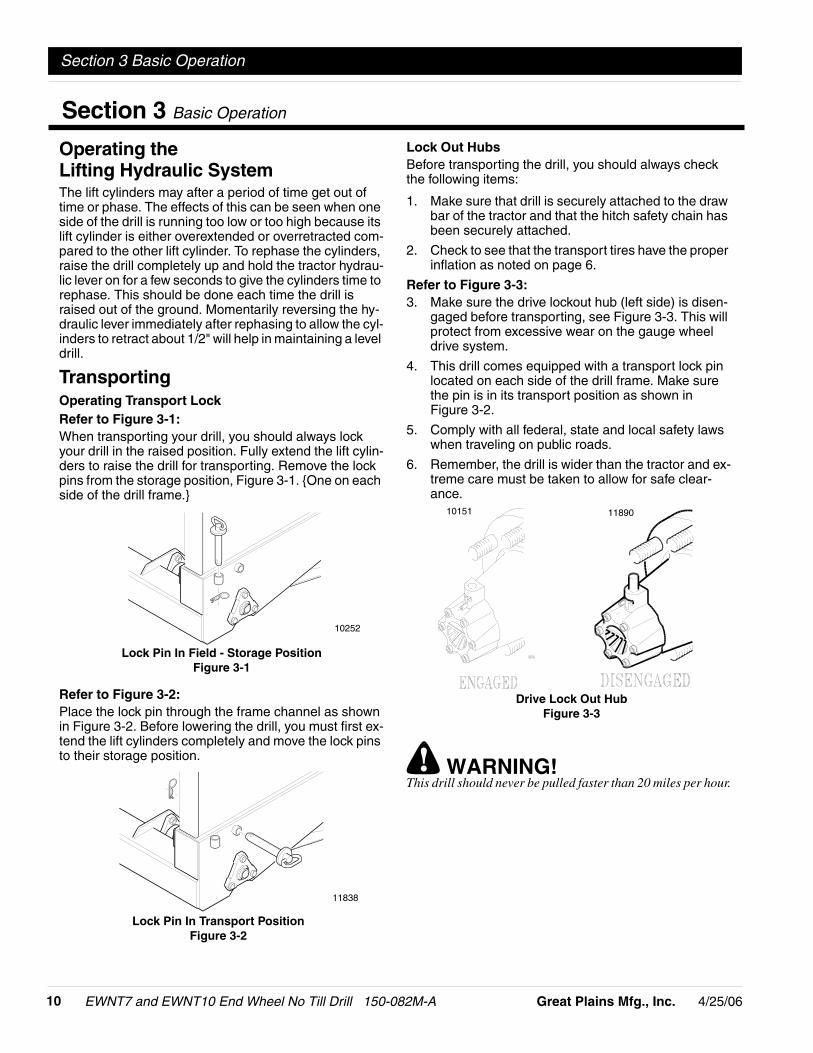
Refer to Figure 3-3:3. Make sure the drive lockout hub (left side) is disen-
gaged before transporting, see Figure 3-3. This willprotect from excessive wear on the gauge wheeldrive system.
4. This drill comes equipped with a transport lock pinlocated on each side of the drill frame. Make surethe pin is in its transport position as shown inFigure 3-2.
5. Comply with all federal, state and local safety lawswhen traveling on public roads.
6. Remember, the drill is wider than the tractor and ex-treme care must be taken to allow for safe clear-ance.
! WARNING!This drill should never be pulled faster than 20 miles per hour.
10252
Lock Pin In Field - Storage PositionFigure 3-1
11838
Lock Pin In Transport PositionFigure 3-2
1189010151
Drive Lock Out HubFigure 3-3
Section 3 Basic Operation
-114/25/06 Great Plains Mfg., Inc.
Section 4 Adjustments
EWNT7 and EWNT10 End Wheel No Till Drill 150-082M-A
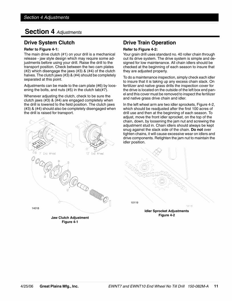
Drive System ClutchRefer to Figure 4-1:The main drive clutch (#1) on your drill is a mechanicalrelease - jaw style design which may require some ad-justments before using your drill. Raise the drill to thetransport position. Check between the two cam plates(#2) which disengage the jaws (#3) & (#4) of the clutchhalves. The clutch jaws (#3) & (#4) should be completelyseparated at this point.
Adjustments can be made to the cam plate (#6) by loos-ening the bolts, and nuts (#5) in the clutch tab(#7).
Whenever adjusting the clutch, check to be sure theclutch jaws (#3) & (#4) are engaged completely whenthe drill is lowered to the field position. The clutch jaws(#3) & (#4) should also be completely disengaged whenthe drill is raised for transport.
Jaw Clutch AdjustmentFigure 4-1
14018
Drive Train OperationRefer to Figure 4-2:Your grain drill uses standard no. 40 roller chain throughout its drive system. The drive system is simple and de-signed for low maintenance. All chain idlers should bechecked at the beginning of each season to insure thatthey are adjusted properly.
To do a maintenance inspection, simply check each idlerto insure that it is taking up any excess chain slack. Onfertilizer and native grass drills the inspection cover forthe drive is located on the outside of the left box end pan-el and this cover must be removed to inspect the fertilizerand native grass drive chain and idler.
In the left wheel arm are two idler sprockets, Figure 4-2,which should be readjusted after the first 100 acres ofdrill use and then at the beginning of each season. Toadjust, move the front idler sprocket, on the top of thechain, down, by loosening the jam nut and screwing theadjustment stud in. Chain idlers should always be keptsnug against the slack side of the chain. Do not overtighten chains, it will cause excessive wear on idlers anddrive components. Retighten the jam nut to maintain theidler position.
10119
Idler Sprocket AdjustmentsFigure 4-2
Section 4 Adjustments
EWNT7 and EWNT10 End Wheel No Till Drill 150-082M-A 4/25/0612 Great Plains Mfg., Inc.
Section 4 Adjustments
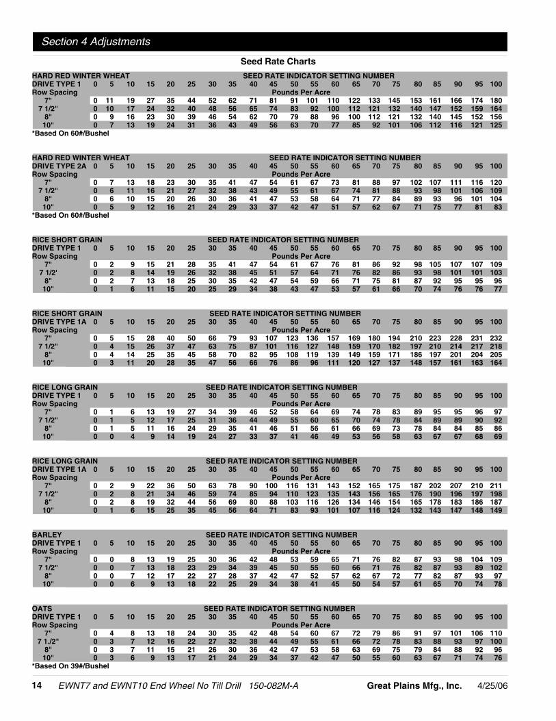
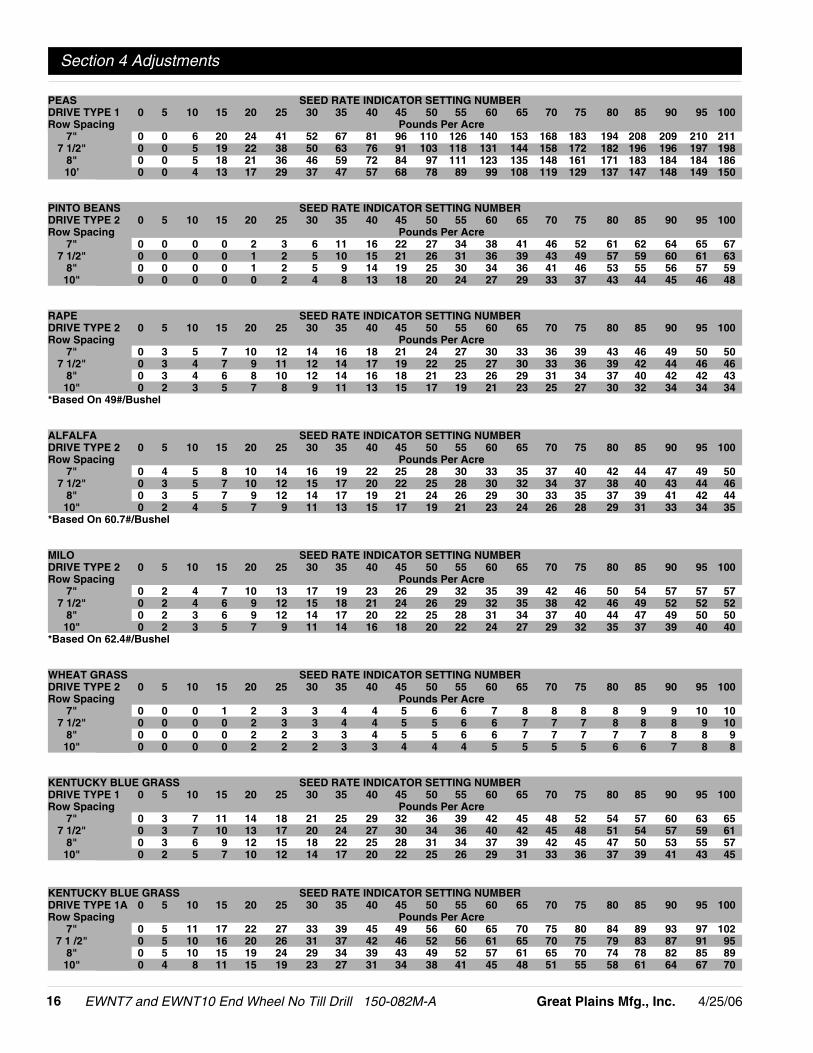
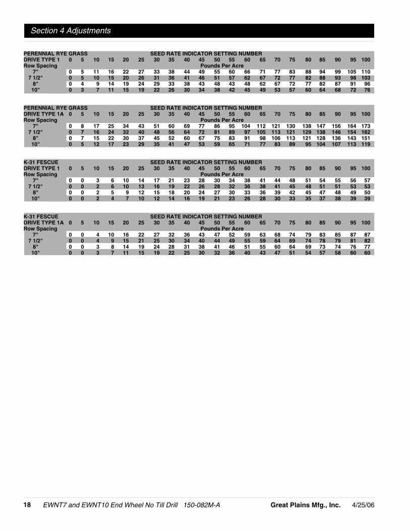
Seeding RateCalibrating the seeding rate requires four steps: arrang-ing the drive sprockets, setting the seed-rate handle, po-sitioning the seed-cup door, and checking the seedingrate.
Refer to the seed-rate charts starting on page 14. Thesecharts list the proper sprocket sizes and seed-rate-han-dle settings for various seeds and seeding rates.
The seed-rate charts are based on cleaned, untreatedseed of average size and test weight. The rates arebased on 9.0 x 24 rib implement tires. Many factors willaffect seeding rates including foreign material, seedtreatment, seed size, field conditions, tire pressure andtest weight. Minor adjustments likely will be needed. Setand check the seeding rate using the procedures below,then adjust the rate as necessary.
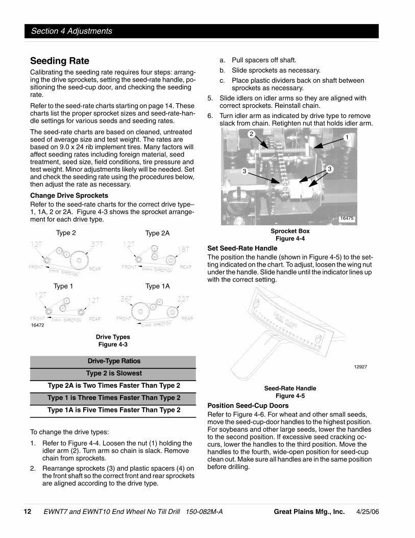
Change Drive SprocketsRefer to the seed-rate charts for the correct drive type–1, 1A, 2 or 2A. Figure 4-3 shows the sprocket arrange-ment for each drive type.
Drive TypesFigure 4-3
To change the drive types:
1. Refer to Figure 4-4. Loosen the nut (1) holding theidler arm (2). Turn arm so chain is slack. Removechain from sprockets.
2. Rearrange sprockets (3) and plastic spacers (4) onthe front shaft so the correct front and rear sprocketsare aligned according to the drive type.
Drive-Type Ratios
Type 2 is Slowest
Type 2A is Two Times Faster Than Type 2
Type 1 is Three Times Faster Than Type 2
Type 1A is Five Times Faster Than Type 2
Type 2 Type 2A
Type 1 Type 1A
16472
a. Pull spacers off shaft.
b. Slide sprockets as necessary.
c. Place plastic dividers back on shaft betweensprockets as necessary.
5. Slide idlers on idler arms so they are aligned withcorrect sprockets. Reinstall chain.
6. Turn idler arm as indicated by drive type to removeslack from chain. Retighten nut that holds idler arm.
Sprocket BoxFigure 4-4
Set Seed-Rate HandleThe position the handle (shown in Figure 4-5) to the set-ting indicated on the chart. To adjust, loosen the wing nutunder the handle. Slide handle until the indicator lines upwith the correct setting.
Seed-Rate HandleFigure 4-5
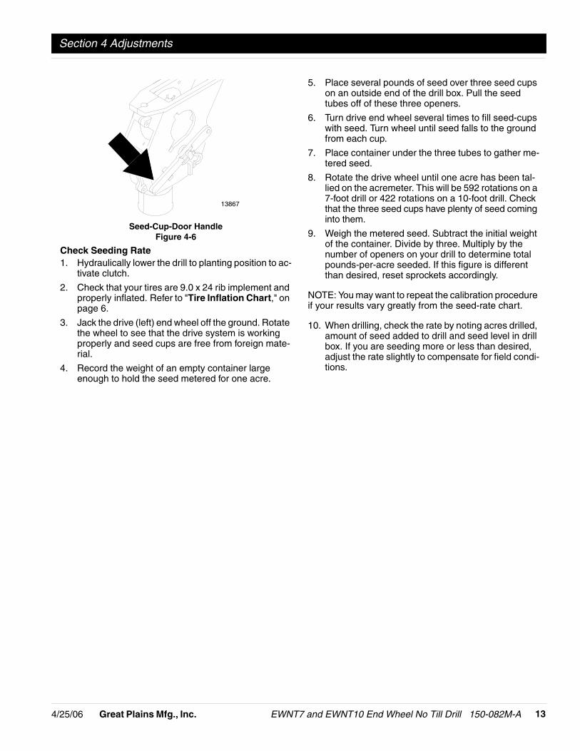
Position Seed-Cup DoorsRefer to Figure 4-6. For wheat and other small seeds,move the seed-cup-door handles to the highest position.For soybeans and other large seeds, lower the handlesto the second position. If excessive seed cracking oc-curs, lower the handles to the third position. Move thehandles to the fourth, wide-open position for seed-cupclean out. Make sure all handles are in the same positionbefore drilling.
12
3
16475
3
12927
-134/25/06 Great Plains Mfg., Inc.
Section 4 Adjustments
EWNT7 and EWNT10 End Wheel No Till Drill 150-082M-A
Seed-Cup-Door HandleFigure 4-6
Check Seeding Rate1. Hydraulically lower the drill to planting position to ac-
tivate clutch.
2. Check that your tires are 9.0 x 24 rib implement andproperly inflated. Refer to "Tire Inflation Chart," onpage 6.
3. Jack the drive (left) end wheel off the ground. Rotatethe wheel to see that the drive system is workingproperly and seed cups are free from foreign mate-rial.
4. Record the weight of an empty container largeenough to hold the seed metered for one acre.
5. Place several pounds of seed over three seed cupson an outside end of the drill box. Pull the seedtubes off of these three openers.
6. Turn drive end wheel several times to fill seed-cupswith seed. Turn wheel until seed falls to the groundfrom each cup.
7. Place container under the three tubes to gather me-tered seed.
8. Rotate the drive wheel until one acre has been tal-lied on the acremeter. This will be 592 rotations on a7-foot drill or 422 rotations on a 10-foot drill. Checkthat the three seed cups have plenty of seed cominginto them.
9. Weigh the metered seed. Subtract the initial weightof the container. Divide by three. Multiply by thenumber of openers on your drill to determine totalpounds-per-acre seeded. If this figure is differentthan desired, reset sprockets accordingly.
NOTE: You may want to repeat the calibration procedureif your results vary greatly from the seed-rate chart.
10. When drilling, check the rate by noting acres drilled,amount of seed added to drill and seed level in drillbox. If you are seeding more or less than desired,adjust the rate slightly to compensate for field condi-tions.
13867
EWNT7 and EWNT10 End Wheel No Till Drill 150-082M-A 4/25/0614 Great Plains Mfg., Inc.
Section 4 Adjustments
HARD RED WINTER WHEAT SEED RATE INDICATOR SETTING NUMBERDRIVE TYPE 1 0 5 10 15 20 25 30 35 40 45 50 55 60 65 70 75 80 85 90 95 100Row Spacing Pounds Per Acre
7" 0 11 19 27 35 44 52 62 71 81 91 101 110 122 133 145 153 161 166 174 1807 1/2" 0 10 17 24 32 40 48 56 65 74 83 92 100 112 121 132 140 147 152 159 164
8" 0 9 16 23 30 39 46 54 62 70 79 88 96 100 112 121 132 140 145 152 15610" 0 7 13 19 24 31 36 43 49 56 63 70 77 85 92 101 106 112 116 121 125
*Based On 60#/Bushel
HARD RED WINTER WHEAT SEED RATE INDICATOR SETTING NUMBERDRIVE TYPE 2A 0 5 10 15 20 25 30 35 40 45 50 55 60 65 70 75 80 85 90 95 100Row Spacing Pounds Per Acre
7" 0 7 13 18 23 30 35 41 47 54 61 67 73 81 88 97 102 107 111 116 1207 1/2" 0 6 11 16 21 27 32 38 43 49 55 61 67 74 81 88 93 98 101 106 109
8" 0 6 10 15 20 26 30 36 41 47 53 58 64 71 77 84 89 93 96 101 10410" 0 5 9 12 16 21 24 29 33 37 42 47 51 57 62 67 71 75 77 81 83
*Based On 60#/Bushel
RICE SHORT GRAIN SEED RATE INDICATOR SETTING NUMBERDRIVE TYPE 1 0 5 10 15 20 25 30 35 40 45 50 55 60 65 70 75 80 85 90 95 100Row Spacing Pounds Per Acre
7" 0 2 9 15 21 28 35 41 47 54 61 67 76 81 86 92 98 105 107 107 1097 1/2' 0 2 8 14 19 26 32 38 45 51 57 64 71 76 82 86 93 98 101 101 103
8" 0 2 7 13 18 25 30 35 42 47 54 59 66 71 75 81 87 92 95 95 9610" 0 1 6 11 15 20 25 29 34 38 43 47 53 57 61 66 70 74 76 76 77
RICE SHORT GRAIN SEED RATE INDICATOR SETTING NUMBERDRIVE TYPE 1A 0 5 10 15 20 25 30 35 40 45 50 55 60 65 70 75 80 85 90 95 100Row Spacing Pounds Per Acre
7" 0 5 15 28 40 50 66 79 93 107 123 136 157 169 180 194 210 223 228 231 2327 1/2" 0 4 15 26 37 47 63 75 87 101 116 127 148 159 170 182 197 210 214 217 218
8" 0 4 14 25 35 45 58 70 82 95 108 119 139 149 159 171 186 197 201 204 20510" 0 3 11 20 28 35 47 56 66 76 86 96 111 120 127 137 148 157 161 163 164
RICE LONG GRAIN SEED RATE INDICATOR SETTING NUMBERDRIVE TYPE 1 0 5 10 15 20 25 30 35 40 45 50 55 60 65 70 75 80 85 90 95 100Row Spacing Pounds Per Acre
7" 0 1 6 13 19 27 34 39 46 52 58 64 69 74 78 83 89 95 95 96 977 1/2" 0 1 5 12 17 25 31 36 44 49 55 60 65 70 74 78 84 89 89 90 92
8" 0 1 5 11 16 24 29 35 41 46 51 56 61 66 69 73 78 84 84 85 8610" 0 0 4 9 14 19 24 27 33 37 41 46 49 53 56 58 63 67 67 68 69
RICE LONG GRAIN SEED RATE INDICATOR SETTING NUMBERDRIVE TYPE 1A 0 5 10 15 20 25 30 35 40 45 50 55 60 65 70 75 80 85 90 95 100Row Spacing Pounds Per Acre
7" 0 2 9 22 36 50 63 78 90 100 116 131 143 152 165 175 187 202 207 210 2117 1/2" 0 2 8 21 34 46 59 74 85 94 110 123 135 143 156 165 176 190 196 197 198
8" 0 2 8 19 32 44 56 69 80 88 103 116 126 134 146 154 165 178 183 186 18710" 0 1 6 15 25 35 45 56 64 71 83 93 101 107 116 124 132 143 147 148 149
BARLEY SEED RATE INDICATOR SETTING NUMBERDRIVE TYPE 1 0 5 10 15 20 25 30 35 40 45 50 55 60 65 70 75 80 85 90 95 100Row Spacing Pounds Per Acre
7" 0 0 8 13 19 25 30 36 42 48 53 59 65 71 76 82 87 93 98 104 1097 1/2" 0 0 7 13 18 23 29 34 39 45 50 55 60 66 71 76 82 87 93 89 102
8" 0 0 7 12 17 22 27 28 37 42 47 52 57 62 67 72 77 82 87 93 9710" 0 0 6 9 13 18 22 25 29 34 38 41 45 50 54 57 61 65 70 74 78
OATS SEED RATE INDICATOR SETTING NUMBERDRIVE TYPE 1 0 5 10 15 20 25 30 35 40 45 50 55 60 65 70 75 80 85 90 95 100Row Spacing Pounds Per Acre
7" 0 4 8 13 18 24 30 35 42 48 54 60 67 72 79 86 91 97 101 106 1107 1./2" 0 3 7 12 16 22 27 32 38 44 49 55 61 66 72 78 83 88 93 97 100
8" 0 3 7 11 15 21 26 30 36 42 47 53 58 63 69 75 79 84 88 92 9610" 0 3 6 9 13 17 21 24 29 34 37 42 47 50 55 60 63 67 71 74 76
*Based On 39#/Bushel
Seed Rate Charts

-154/25/06 Great Plains Mfg., Inc.
Section 4 Adjustments
EWNT7 and EWNT10 End Wheel No Till Drill 150-082M-A
RYE SEED RATE INDICATOR SETTING NUMBERDRIVE TYPE 2 0 5 10 15 20 25 30 35 40 45 50 55 60 65 70 75 80 85 90 95 100Row Spacing Pounds Per Acre
7" 0 0 3 6 9 12 15 17 22 23 25 29 32 35 37 41 45 48 49 52 537 1/2" 0 0 3 5 8 11 14 16 21 22 24 28 30 33 35 38 42 46 46 49 49
8" 0 0 3 5 8 10 13 15 19 20 23 26 29 31 33 36 39 43 44 46 4710’ 0 0 2 4 6 8 10 14 16 17 19 21 23 25 27 29 32 34 35 37 38
MILLET SEED RATE INDICATOR SETTING NUMBERDRIVE TYPE 2 0 5 10 15 20 25 30 35 40 45 50 55 60 65 70 75 80 85 90 95 100Row Spacing Pounds Per Acre
7" 0 1 4 6 9 12 14 16 19 22 25 28 32 35 39 42 46 51 53 53 547 1/2" 0 1 3 5 8 11 13 15 17 21 24 27 31 33 36 40 44 47 49 50 51
8" 0 1 3 5 8 10 12 14 16 19 22 25 28 30 34 38 41 45 46 47 4810" 0 0 2 4 6 8 9 11 13 15 18 21 23 25 27 29 33 36 37 38 39
BUCKWHEAT SEED RATE INDICATOR SETTING NUMBERDRIVE TYPE 1 0 5 10 15 20 25 30 35 40 45 50 55 60 65 70 75 80 85 90 95 100Row Spacing Pounds Per Acre
7" 0 4 10 18 25 32 40 48 52 63 73 82 86 96 104 117 128 142 151 152 1557 1/2" 0 3 9 17 23 30 37 46 49 60 68 77 81 90 98 111 121 134 142 146 146
8" 0 3 9 16 21 28 35 43 46 57 63 73 76 85 92 104 113 126 133 134 13710" 0 3 7 12 18 23 28 34 37 46 52 58 61 68 74 83 91 100 106 107 109
FLAX OR SUDAN SEED RATE INDICATOR SETTING NUMBERDRIVE TYPE 2 0 5 10 15 20 25 30 35 40 45 50 55 60 65 70 75 80 85 90 95 100Row Spacing Pounds Per Acre
7" 0 1 4 6 8 12 15 17 21 24 27 31 33 36 38 42 47 50 53 56 577 1/2" 0 1 3 5 7 11 14 16 20 22 25 29 31 34 36 40 44 47 50 52 54
8" 0 1 3 5 7 10 13 15 19 21 24 27 29 32 34 37 41 44 47 49 5110" 0 0 3 4 6 8 10 12 15 17 19 22 23 25 27 30 33 36 38 39 41
SUNFLOWERS SEED RATE INDICATOR SETTING NUMBERDRIVE TYPE 2 0 5 10 15 20 25 30 35 40 45 50 55 60 65 70 75 80 85 90 95 100Row Spacing Pounds Per Acre
7" 0 0 0 3 6 9 12 15 17 20 25 29 32 35 37 41 44 46 49 52 557 1./2" 0 0 0 3 6 8 11 14 16 19 23 27 30 33 35 38 41 44 46 49 52
8" 0 0 0 3 5 8 10 13 15 18 22 25 28 31 34 35 38 41 44 46 4910" 0 0 0 2 4 6 8 10 12 15 17 21 23 25 26 29 31 33 35 37 39
SOYBEANS SEED RATE INDICATOR SETTING NUMBERDRIVE TYPE 1 0 5 10 15 20 25 30 35 40 45 50 55 60 65 70 75 80 85 90 95 100Row Spacing Pounds Per Acre
7" 0 0 8 21 34 46 59 70 82 95 107 118 132 144 154 166 174 184 195 201 2077 1/2" 0 0 7 20 31 42 54 64 75 87 98 108 120 131 141 152 159 168 178 184 189
8" 0 0 7 19 29 40 51 61 71 83 93 103 114 125 134 145 152 160 169 175 18010" 0 0 6 15 23 32 41 49 57 66 75 82 91 100 107 116 121 128 135 140 144
*Based On 59.1#/Bushel
SOYBEANS SEED RATE INDICATOR SETTING NUMBERDRIVE TYPE 2 0 5 10 15 20 25 30 35 40 45 50 55 60 65 70 75 80 85 90 95 100Row Spacing Pounds Per Acre
7" 0 0 2 7 11 15 19 23 27 31 35 38 43 47 50 54 57 60 63 65 677 1/2" 0 0 2 6 10 13 17 21 24 28 32 35 39 42 46 49 52 54 58 60 61
8" 0 0 2 6 9 13 17 20 23 27 30 33 37 40 43 47 49 52 55 57 5810" 0 0 2 5 8 10 13 16 18 21 24 27 30 32 35 37 39 41 44 45 47
*Based On 59.1#/Bushel
SOYBEANS SEED RATE INDICATOR SETTING NUMBERDRIVE TYPE 2A 0 5 10 15 20 25 30 35 40 45 50 55 60 65 70 75 80 85 90 95 100Row Spacing Pounds Per Acre
7" 0 0 5 14 22 30 39 49 55 64 72 79 88 96 103 111 116 123 130 134 1387 1/2" 0 0 5 13 20 28 36 42 50 58 65 72 80 87 94 101 106 112 118 123 126
8" 0 0 4 12 19 26 34 40 47 55 62 68 76 83 89 96 101 107 113 117 12010" 0 0 4 10 16 21 27 32 38 44 50 55 61 67 70 77 81 85 910 93 96
*Based On 59.1#/Bushel Setting the feed cup adjustment lever between 50 & 80 allows for optimum seeding of soybeans.
EWNT7 and EWNT10 End Wheel No Till Drill 150-082M-A 4/25/0616 Great Plains Mfg., Inc.
Section 4 Adjustments
PEAS SEED RATE INDICATOR SETTING NUMBERDRIVE TYPE 1 0 5 10 15 20 25 30 35 40 45 50 55 60 65 70 75 80 85 90 95 100Row Spacing Pounds Per Acre
7" 0 0 6 20 24 41 52 67 81 96 110 126 140 153 168 183 194 208 209 210 2117 1/2" 0 0 5 19 22 38 50 63 76 91 103 118 131 144 158 172 182 196 196 197 198
8" 0 0 5 18 21 36 46 59 72 84 97 111 123 135 148 161 171 183 184 184 18610’ 0 0 4 13 17 29 37 47 57 68 78 89 99 108 119 129 137 147 148 149 150
PINTO BEANS SEED RATE INDICATOR SETTING NUMBERDRIVE TYPE 2 0 5 10 15 20 25 30 35 40 45 50 55 60 65 70 75 80 85 90 95 100Row Spacing Pounds Per Acre
7" 0 0 0 0 2 3 6 11 16 22 27 34 38 41 46 52 61 62 64 65 677 1/2" 0 0 0 0 1 2 5 10 15 21 26 31 36 39 43 49 57 59 60 61 63
8" 0 0 0 0 1 2 5 9 14 19 25 30 34 36 41 46 53 55 56 57 5910" 0 0 0 0 0 2 4 8 13 18 20 24 27 29 33 37 43 44 45 46 48
RAPE SEED RATE INDICATOR SETTING NUMBERDRIVE TYPE 2 0 5 10 15 20 25 30 35 40 45 50 55 60 65 70 75 80 85 90 95 100Row Spacing Pounds Per Acre
7" 0 3 5 7 10 12 14 16 18 21 24 27 30 33 36 39 43 46 49 50 507 1/2" 0 3 4 7 9 11 12 14 17 19 22 25 27 30 33 36 39 42 44 46 46
8" 0 3 4 6 8 10 12 14 16 18 21 23 26 29 31 34 37 40 42 42 4310" 0 2 3 5 7 8 9 11 13 15 17 19 21 23 25 27 30 32 34 34 34
*Based On 49#/Bushel
ALFALFA SEED RATE INDICATOR SETTING NUMBERDRIVE TYPE 2 0 5 10 15 20 25 30 35 40 45 50 55 60 65 70 75 80 85 90 95 100Row Spacing Pounds Per Acre
7" 0 4 5 8 10 14 16 19 22 25 28 30 33 35 37 40 42 44 47 49 507 1/2" 0 3 5 7 10 12 15 17 20 22 25 28 30 32 34 37 38 40 43 44 46
8" 0 3 5 7 9 12 14 17 19 21 24 26 29 30 33 35 37 39 41 42 4410" 0 2 4 5 7 9 11 13 15 17 19 21 23 24 26 28 29 31 33 34 35
*Based On 60.7#/Bushel
MILO SEED RATE INDICATOR SETTING NUMBERDRIVE TYPE 2 0 5 10 15 20 25 30 35 40 45 50 55 60 65 70 75 80 85 90 95 100Row Spacing Pounds Per Acre
7" 0 2 4 7 10 13 17 19 23 26 29 32 35 39 42 46 50 54 57 57 577 1/2" 0 2 4 6 9 12 15 18 21 24 26 29 32 35 38 42 46 49 52 52 52
8" 0 2 3 6 9 12 14 17 20 22 25 28 31 34 37 40 44 47 49 50 5010" 0 2 3 5 7 9 11 14 16 18 20 22 24 27 29 32 35 37 39 40 40
*Based On 62.4#/Bushel
WHEAT GRASS SEED RATE INDICATOR SETTING NUMBERDRIVE TYPE 2 0 5 10 15 20 25 30 35 40 45 50 55 60 65 70 75 80 85 90 95 100Row Spacing Pounds Per Acre
7" 0 0 0 1 2 3 3 4 4 5 6 6 7 8 8 8 8 9 9 10 107 1/2" 0 0 0 0 2 3 3 4 4 5 5 6 6 7 7 7 8 8 8 9 10
8" 0 0 0 0 2 2 3 3 4 5 5 6 6 7 7 7 7 7 8 8 910" 0 0 0 0 2 2 2 3 3 4 4 4 5 5 5 5 6 6 7 8 8
KENTUCKY BLUE GRASS SEED RATE INDICATOR SETTING NUMBERDRIVE TYPE 1 0 5 10 15 20 25 30 35 40 45 50 55 60 65 70 75 80 85 90 95 100Row Spacing Pounds Per Acre
7" 0 3 7 11 14 18 21 25 29 32 36 39 42 45 48 52 54 57 60 63 657 1/2" 0 3 7 10 13 17 20 24 27 30 34 36 40 42 45 48 51 54 57 59 61
8" 0 3 6 9 12 15 18 22 25 28 31 34 37 39 42 45 47 50 53 55 5710" 0 2 5 7 10 12 14 17 20 22 25 26 29 31 33 36 37 39 41 43 45
KENTUCKY BLUE GRASS SEED RATE INDICATOR SETTING NUMBERDRIVE TYPE 1A 0 5 10 15 20 25 30 35 40 45 50 55 60 65 70 75 80 85 90 95 100Row Spacing Pounds Per Acre
7" 0 5 11 17 22 27 33 39 45 49 56 60 65 70 75 80 84 89 93 97 1027 1 /2" 0 5 10 16 20 26 31 37 42 46 52 56 61 65 70 75 79 83 87 91 95
8" 0 5 10 15 19 24 29 34 39 43 49 52 57 61 65 70 74 78 82 85 8910" 0 4 8 11 15 19 23 27 31 34 38 41 45 48 51 55 58 61 64 67 70

-174/25/06 Great Plains Mfg., Inc.
Section 4 Adjustments
EWNT7 and EWNT10 End Wheel No Till Drill 150-082M-A
ORCHARD GRASS SEED RATE INDICATOR SETTING NUMBERDRIVE TYPE 2A 0 5 10 15 20 25 30 35 40 45 50 55 60 65 70 75 80 85 90 95 100Row Spacing Pounds Per Acre
7" .3 .8 2.1 3.3 4.4 5.6 6.9 8.0 9.2 10.3 11.6 12.8 13.9 15.1 16.4 17.5 18.7 19.8 21.1 22.3 23.47 1/2" .3 .8 2.0 3.1 4.1 5.2 6.4 7.5 8.6 9.7 10.9 12.0 13.0 14.1 15.3 16.4 17.5 18.6 19.8 20.9 21.9
8" .3 .7 1.9 2.9 3.9 4.9 6.0 7.0 8.0 9.0 10.2 11.2 12.2 13.2 14.3 15.3 16.3 17.3 18.5 19.5 20.510" .2 .6 1.5 2.2 3.0 3.8 4.7 5.5 6.3 7.1 8.0 8.8 9.6 10.3 11.2 12.0 12.8 13.6 14.5 15.3 16.1
ORCHARD GRASS SEED RATE INDICATOR SETTING NUMBERDRIVE TYPE 2 0 5 10 15 20 25 30 35 40 45 50 55 60 65 70 75 80 85 90 95 100Row Spacing Pounds Per Acre
7" .2 .4 1.0 1.6 2.1 2.7 3.3 3.9 4.5 5.0 5.7 6.2 6.8 7.3 8.0 8.5 9.1 9.6 10.3 10.8 11.47 1/2" .1 .4 1.0 1.5 2.0 2.5 3.1 3.7 4.2 4.7 5.3 5.8 6.3 6.9 7.5 8.0 8.5 9.0 9.6 10.1 10.7
8" .1 .3 .9 1.4 1.9 2.4 2.9 3.4 3.9 4.4 4.9 5.4 5.9 6.4 7.0 7.5 7.9 8.4 9.0 9.5 10.010" .1 .3 .7 1.1 1.5 1.9 2.3 2.7 3.1 3.4 3.9 4.3 4.7 5.0 5.5 5.9 6.2 6.6 7.1 7.4 7.8
ORCHARD GRASS SEED RATE INDICATOR SETTING NUMBERDRIVE TYPE 1A 0 5 10 15 20 25 30 35 40 45 50 55 60 65 70 75 80 85 90 95 100Row Spacing Pounds Per Acre
7" .8 2.0 5.2 8.0 10.8 13.6 16.8 19.6 22.4 25.2 28.4 31.2 34.0 36.8 40.0 42.8 45.6 48.4 51.6 54.4 57.27 1/2" .8 1.9 4.9 7.5 10.1 12.8 15.8 18.4 21.0 23.6 26.6 29.3 31.9 34.5 37.5 40.1 42.8 45.4 48.4 51.0 53.6
8" .7 1.8 4.6 7.0 9.5 11.9 14.7 17.2 19.6 22.1 24.9 27.3 29.8 32.2 35.0 37.5 39.9 42.4 45.2 47.6 50.110" .6 1.4 3.6 5.5 7.4 9.4 11.6 13.5 15.4 17.3 19.5 21.5 23.4 25.3 27.5 29.4 31.4 33.3 35.5 37.4 39.3
ORCHARD GRASS SEED RATE INDICATOR SETTING NUMBERDRIVE TYPE 1 0 5 10 15 20 25 30 35 40 45 50 55 60 65 70 75 80 85 90 95 100Row Spacing Pounds Per Acre
7" .5 1.2 3.2 4.9 6.6 8.3 10.3 12.0 13.7 15.5 17.4 19.1 20.9 22.6 24.5 26.3 28.0 29.7 31.7 33.4 35.17 1/2" .5 1.2 3.0 4.6 6.2 7.8 9.7 11.3 12.9 14.5 16.3 17.9 19.6 21.2 23.0 24.6 26.2 27.8 29.7 31.3 32.9
8" .4 1.1 2.8 4.3 5.8 7.3 9.0 10.5 12.0 13.5 15.2 16.8 18.3 19.8 21.5 23.0 24.5 26.0 27.7 29.2 30.710" .3 .8 2.2 3.4 4.6 5.7 7.1 8.3 9.4 10.6 12.0 13.2 14.3 15.5 16.9 18.1 19.2 20.4 21.8 22.9 24.1
BURMUDA GRASS SEED RATE INDICATOR SETTING NUMBERDRIVE TYPE 1 0 5 10 15 20 25 30 35 40 45 50 55 60 65 70 75 80 85 90 95 100Row Spacing Pounds Per Acre
7" 0 8 14 22 28 34 40 47 53 59 65 71 77 83 89 96 102 108 114 120 1267 1/2" 0 8 13 21 26 32 38 44 49 55 61 67 72 78 84 90 95 101 107 113 118
8" 0 7 12 19 25 30 35 41 46 51 57 62 68 73 78 84 89 94 100 105 11110" 0 6 10 15 19 24 28 32 36 40 45 49 53 57 61 66 70 74 78 83 87
BURMUDA GRASS SEED RATE INDICATOR SETTING NUMBERDRIVE TYPE 1A 0 5 10 15 20 25 30 35 40 45 50 55 60 65 70 75 80 85 90 95 100Row Spacing Pounds Per Acre
7" 0 14 23 36 46 56 66 76 86 96 106 116 126 136 146 156 166 176 186 196 2067 1/2" 0 13 21 34 43 52 62 71 81 91 99 109 118 127 137 146 156 165 174 184 193
8" 0 12 20 31 40 49 57 67 75 84 92 102 110 119 127 137 145 154 162 172 18010" 0 9 15 25 32 38 45 52 59 66 73 80 87 93 100 107 114 121 128 135 142
BURMUDA GRASS SEED RATE INDICATOR SETTING NUMBERDRIVE TYPE 2 0 5 10 15 20 25 30 35 40 45 50 55 60 65 70 75 80 85 90 95 100Row Spacing Pounds Per Acre
7" 0 3 5 7 9 11 13 15 17 19 21 23 25 27 29 31 33 35 37 39 417 1/2" 0 3 4 7 9 10 12 14 16 18 20 22 24 25 27 29 31 33 35 37 38
8" 0 2 4 6 8 10 11 13 15 17 18 20 22 24 25 27 29 31 32 34 3610" 0 2 3 5 6 8 9 10 12 13 15 16 17 19 20 21 23 24 25 27 28
BURMUDA GRASS SEED RATE INDICATOR SETTING NUMBERDRIVE TYPE 2A 0 5 10 15 20 25 30 35 40 45 50 55 60 65 70 75 80 85 90 95 100Row Spacing Pounds Per Acre
7" 0 6 9 15 19 23 27 31 35 39 43 47 52 56 60 64 68 72 76 80 847 1/2" 0 5 9 14 18 21 25 29 33 37 41 45 48 52 56 60 64 67 71 75 79
8" 0 5 8 13 16 20 24 27 31 34 38 42 45 49 52 56 59 53 66 70 7410" 0 4 6 10 13 16 19 21 24 27 30 33 35 38 41 44 47 49 52 55 58
EWNT7 and EWNT10 End Wheel No Till Drill 150-082M-A 4/25/0618 Great Plains Mfg., Inc.
Section 4 Adjustments
PERENNIAL RYE GRASS SEED RATE INDICATOR SETTING NUMBERDRIVE TYPE 1 0 5 10 15 20 25 30 35 40 45 50 55 60 65 70 75 80 85 90 95 100Row Spacing Pounds Per Acre
7" 0 5 11 16 22 27 33 38 44 49 55 60 66 71 77 83 88 94 99 105 1107 1/2" 0 5 10 15 20 26 31 36 41 46 51 57 62 67 72 77 82 88 93 98 103
8" 0 4 9 14 19 24 29 33 38 43 48 43 48 62 67 72 77 82 87 91 9610" 0 3 7 11 15 19 22 26 30 34 38 42 45 49 53 57 60 64 68 72 76
PERENNIAL RYE GRASS SEED RATE INDICATOR SETTING NUMBERDRIVE TYPE 1A 0 5 10 15 20 25 30 35 40 45 50 55 60 65 70 75 80 85 90 95 100Row Spacing Pounds Per Acre
7" 0 8 17 25 34 43 51 60 69 77 86 95 104 112 121 130 138 147 156 164 1737 1/2" 0 7 16 24 32 40 48 56 64 72 81 89 97 105 113 121 129 138 146 154 162
8" 0 7 15 22 30 37 45 52 60 67 75 83 91 98 106 113 121 128 136 143 15110" 0 5 12 17 23 29 35 41 47 53 59 65 71 77 83 89 95 104 107 113 119
K-31 FESCUE SEED RATE INDICATOR SETTING NUMBERDRIVE TYPE 1 0 5 10 15 20 25 30 35 40 45 50 55 60 65 70 75 80 85 90 95 100Row Spacing Pounds Per Acre
7" 0 0 3 6 10 14 17 21 23 28 30 34 38 41 44 48 51 54 55 56 577 1/2" 0 0 2 6 10 13 16 19 22 26 28 32 36 38 41 45 48 51 51 53 53
8" 0 0 2 5 9 12 15 18 20 24 27 30 33 36 39 42 45 47 48 49 5010" 0 0 2 4 7 10 12 14 16 19 21 23 26 28 30 33 35 37 38 39 39
K-31 FESCUE SEED RATE INDICATOR SETTING NUMBERDRIVE TYPE 1A 0 5 10 15 20 25 30 35 40 45 50 55 60 65 70 75 80 85 90 95 100Row Spacing Pounds Per Acre
7" 0 0 4 10 16 22 27 32 36 43 47 52 59 63 68 74 79 83 85 87 877 1/2" 0 0 4 9 15 21 25 30 34 40 44 49 55 59 64 69 74 78 79 81 82
8" 0 0 3 8 14 19 24 28 31 38 41 46 51 55 60 64 69 73 74 76 7710" 0 0 3 7 11 15 19 22 25 30 32 36 40 43 47 51 54 57 58 60 60

-194/25/06 Great Plains Mfg., Inc.
Section 4 Adjustments
EWNT7 and EWNT10 End Wheel No Till Drill 150-082M-A
Fertilizer DriveThe fertilizer feed rate is directly related to your groundspeed so there are no chains or sprockets to adjust in or-der to change your rate. The rate is controlled by the fer-tilizer outlet opening size which is controlled by theadjustment knob on the back of the fertilizer tray. For fer-tilizer rates, refer to the chart below.
Fertilizer RateGreat Plains End Wheel No-Till Fertilizer Drills have apartition, Figure 4-7, dividing the seed and fertilizer com-partments. In the partitions are removable panels to al-low the drill to be used with all seed, Figure 4-7.
If fertilizer is not being used with grain, remove chainfrom fertilizer drive sprocket to eliminate unnecessarywear on the fertilizer drive system.
If total box capacity is desired for grain, remove seed/fer-tilizer partitions and set fertilizer rate adjustment lever at
"0" setting so as not to allow any seed to escape throughthe fertilizer outlets.
The application rate of dry granular fertilizer is affectedby many factors: Fertilizer type and density, relative hu-midity, and the moisture content of the material itself.
Due to these variables, the chart below should be usedonly to closely approximate the amount of fertilizer beingapplied.
10114
Divided Panel Panel Removed
Figure 4-7
INDICATOR SETTING NUMBERRow 10 15 20 25 30 35 40 45 50 55 60 65 70 75 80 85 90 95 100Spacing Pounds Per Acre
7" 0 11 21 40 57 75 93 111 128 144 163 181 196 217 232 245 252 258 2607 1/2" 0 10 19 37 51 69 85 100 116 131 148 164 178 198 211 223 230 234 236
8" 0 10 19 37 51 69 85 100 116 131 148 164 178 198 211 223 230 234 23610" 0 8 16 29 41 55 68 80 93 105 119 132 143 158 169 178 184 187 189
The preceding chart has been computed using fertilizer that has a density of 65 pounds/cubic foot. If you areapplying fertilizer that has a density other than this, use the following table:
Density 45 50 55 60 65 70 75 80Conversion Factor 1.45 1.30 1.20 1.10 1.00 0.93 0.87 0.81
EXAMPLE: You are using fertilizer with a 75 pound/cubicfoot density and you desire a rate of 100 pounds per acre.Multiply 100 x 0.87 = 87 pounds. Therefore, use the set-ting closest to 87 pounds.
7’ & 10’ Fertilizer Application Chart
EWNT7 and EWNT10 End Wheel No Till Drill 150-082M-A 4/25/0620 Great Plains Mfg., Inc.
Section 4 Adjustments
Native Grass DriveNative grass metering is directly related to the revolu-tions of the clutch shaft per acre. The different sprocketcombinations are required to give a broad range of plant-ing rates. The sprocket changes are made at the left endof the drill, inside the double wall end panel. For nativegrass seeding rates and sprocket combinations, refer topage 21.
Native Grass RateGreat Plains End Wheel No-Till Native Grass Drill has apartition dividing the seed and native grass compart-ments. Capacity of the seed box is 1.3 bushels per foot,and the capacity of the native grass box is 1.2 bushelsper foot.
If the native grass is not being used, remove the chainfrom the native grass drive sprocket to eliminate wear onthe native grass drive system.
Native Grass Seeding Adjustments
1. Rotate the drive wheel to see that the feed cups anddrive are working properly and are free from foreignmatter
NOTE: Seeding rates vary greatly with variations intypes of seeds being drilled. The seed rate chart onthe following page is based on a seed mix of 5.7# ofpure live seed per 11.1# of bulk. The pure live seedmix was Big Blue-1.5#, Little Blue-.8#, Side OatsGrama-.6#, Western Wheat Grass-1#, SwitchGrass-.3#, and Indian Grass-1.5#. Factors which af-fect seeding rates are: weight of seed, size of seed,relative humidity and moisture content of the seed it-self, ratio of inert material to seed, different propor-tions of seed types affecting density, and tireconfiguration, pressure and slippage. We recom-mend that you test and adjust your drill usingthe procedures listed below to help insure an ac-curate seeding rate.
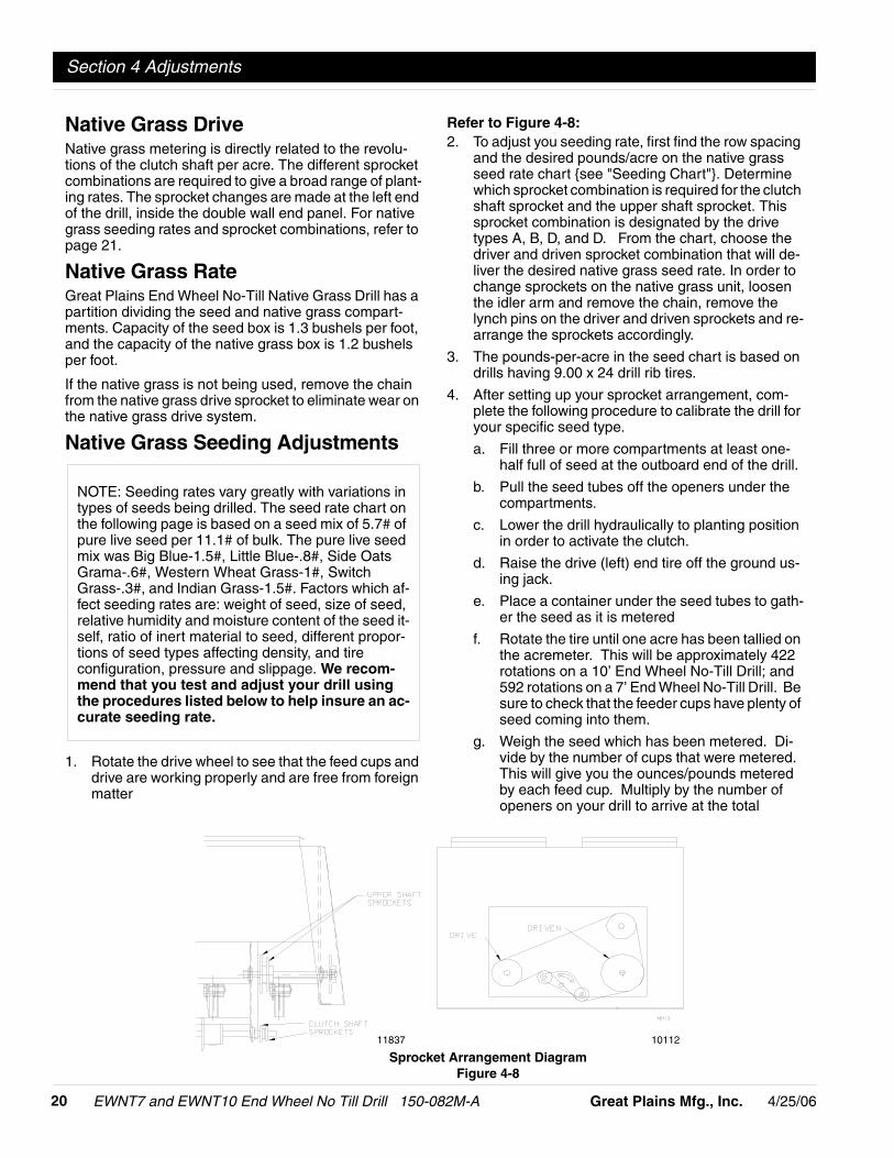
Refer to Figure 4-8:2. To adjust you seeding rate, first find the row spacing
and the desired pounds/acre on the native grassseed rate chart {see "Seeding Chart"}. Determinewhich sprocket combination is required for the clutchshaft sprocket and the upper shaft sprocket. Thissprocket combination is designated by the drivetypes A, B, D, and D. From the chart, choose thedriver and driven sprocket combination that will de-liver the desired native grass seed rate. In order tochange sprockets on the native grass unit, loosenthe idler arm and remove the chain, remove thelynch pins on the driver and driven sprockets and re-arrange the sprockets accordingly.
3. The pounds-per-acre in the seed chart is based ondrills having 9.00 x 24 drill rib tires.
4. After setting up your sprocket arrangement, com-plete the following procedure to calibrate the drill foryour specific seed type.
a. Fill three or more compartments at least one-half full of seed at the outboard end of the drill.
b. Pull the seed tubes off the openers under thecompartments.
c. Lower the drill hydraulically to planting positionin order to activate the clutch.
d. Raise the drive (left) end tire off the ground us-ing jack.
e. Place a container under the seed tubes to gath-er the seed as it is metered
f. Rotate the tire until one acre has been tallied onthe acremeter. This will be approximately 422rotations on a 10’ End Wheel No-Till Drill; and592 rotations on a 7’ End Wheel No-Till Drill. Besure to check that the feeder cups have plenty ofseed coming into them.
g. Weigh the seed which has been metered. Di-vide by the number of cups that were metered.This will give you the ounces/pounds meteredby each feed cup. Multiply by the number ofopeners on your drill to arrive at the total
10112
Sprocket Arrangement DiagramFigure 4-8
11837
-214/25/06 Great Plains Mfg., Inc.
Section 4 Adjustments
EWNT7 and EWNT10 End Wheel No Till Drill 150-082M-A
pounds-per-acre your drill would meter at thatsetting. If this figure is different than desired,change your sprocket arrangement accordingly.
5. You may want to repeat the calibration procedure ifthe results of your calibration vary greatly from whatis listed on the seed rate chart.
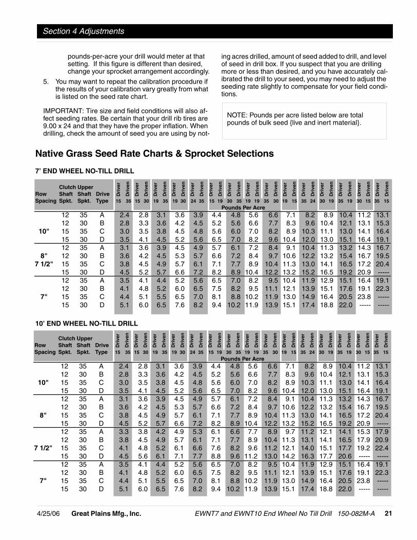
IMPORTANT: Tire size and field conditions will also af-fect seeding rates. Be certain that your drill rib tires are9.00 x 24 and that they have the proper inflation. Whendrilling, check the amount of seed you are using by not-
ing acres drilled, amount of seed added to drill, and levelof seed in drill box. If you suspect that you are drillingmore or less than desired, and you have accurately cal-ibrated the drill to your seed, you may need to adjust theseeding rate slightly to compensate for your field condi-tions.
NOTE: Pounds per acre listed below are totalpounds of bulk seed {live and inert material}.
10’ END WHEEL NO-TILL DRILL
Dri
ver
Dri
ven
Dri
ver
Dri
ven
Dri
ver
Dri
ven
Dri
ver
Dri
ven
Dri
ver
Dri
ven
Dri
ver
Dri
ven
Dri
ver
Dri
ven
Dri
ver
Dri
ven
Dri
ver
Dri
ven
Dri
ver
Dri
ven
Dri
ver
Dri
ven
Dri
ver
Dri
ven
Dri
ver
Dri
ven
Dri
ver
Dri
ven
Dri
ver
Dri
ven
Dri
ver
Dri
ven
Dri
ver
Dri
ven
Dri
ver
Dri
ven
Dri
ver
Dri
ven
Dri
ver
Dri
ven
Dri
ver
Dri
ven
Dri
ver
Dri
ven
Dri
ver
Dri
ven
Dri
ver
Dri
ven
Dri
ver
Dri
ven
Dri
ver
Dri
ven
Dri
ver
Dri
ven
Dri
ver
Dri
ven
Dri
ver
Dri
ven
Dri
ver
Dri
ven
7’ END WHEEL NO-TILL DRILL
Native Grass Seed Rate Charts & Sprocket Selections
Clutch UpperRow Shaft Shaft DriveSpacing Spkt. Spkt. Type 15 35 15 30 19 35 19 30 24 35 15 19 30 35 19 19 35 30 19 15 35 24 30 19 35 19 30 15 35 15
Pounds Per Acre12 35 A 2.4 2.8 3.1 3.6 3.9 4.4 4.8 5.6 6.6 7.1 8.2 8.9 10.4 11.2 13.112 30 B 2.8 3.3 3.6 4.2 4.5 5.2 5.6 6.6 7.7 8.3 9.6 10.4 12.1 13.1 15.3
10" 15 35 C 3.0 3.5 3.8 4.5 4.8 5.6 6.0 7.0 8.2 8.9 10.3 11.1 13.0 14.1 16.415 30 D 3.5 4.1 4.5 5.2 5.6 6.5 7.0 8.2 9.6 10.4 12.0 13.0 15.1 16.4 19.112 35 A 3.1 3.6 3.9 4.5 4.9 5.7 6.1 7.2 8.4 9.1 10.4 11.3 13.2 14.3 16.7
8" 12 30 B 3.6 4.2 4.5 5.3 5.7 6.6 7.2 8.4 9.7 10.6 12.2 13.2 15.4 16.7 19.57 1/2" 15 35 C 3.8 4.5 4.9 5.7 6.1 7.1 7.7 8.9 10.4 11.3 13.0 14.1 16.5 17.2 20.4
15 30 D 4.5 5.2 5.7 6.6 7.2 8.2 8.9 10.4 12.2 13.2 15.2 16.5 19.2 20.9 -----12 35 A 3.5 4.1 4.4 5.2 5.6 6.5 7.0 8.2 9.5 10.4 11.9 12.9 15.1 16.4 19.112 30 B 4.1 4.8 5.2 6.0 6.5 7.5 8.2 9.5 11.1 12.1 13.9 15.1 17.6 19.1 22.3
7" 15 35 C 4.4 5.1 5.5 6.5 7.0 8.1 8.8 10.2 11.9 13.0 14.9 16.4 20.5 23.8 -----15 30 D 5.1 6.0 6.5 7.6 8.2 9.4 10.2 11.9 13.9 15.1 17.4 18.8 22.0 ----- -----
Clutch UpperRow Shaft Shaft DriveSpacing Spkt. Spkt. Type 15 35 15 30 19 35 19 30 24 35 15 19 30 35 19 19 35 30 19 15 35 24 30 19 35 19 30 15 35 15
Pounds Per Acre12 35 A 2.4 2.8 3.1 3.6 3.9 4.4 4.8 5.6 6.6 7.1 8.2 8.9 10.4 11.2 13.112 30 B 2.8 3.3 3.6 4.2 4.5 5.2 5.6 6.6 7.7 8.3 9.6 10.4 12.1 13.1 15.3
10" 15 35 C 3.0 3.5 3.8 4.5 4.8 5.6 6.0 7.0 8.2 8.9 10.3 11.1 13.0 14.1 16.415 30 D 3.5 4.1 4.5 5.2 5.6 6.5 7.0 8.2 9.6 10.4 12.0 13.0 15.1 16.4 19.112 35 A 3.1 3.6 3.9 4.5 4.9 5.7 6.1 7.2 8.4 9.1 10.4 11.3 13.2 14.3 16.712 30 B 3.6 4.2 4.5 5.3 5.7 6.6 7.2 8.4 9.7 10.6 12.2 13.2 15.4 16.7 19.5
8" 15 35 C 3.8 4.5 4.9 5.7 6.1 7.1 7.7 8.9 10.4 11.3 13.0 14.1 16.5 17.2 20.415 30 D 4.5 5.2 5.7 6.6 7.2 8.2 8.9 10.4 12.2 13.2 15.2 16.5 19.2 20.9 -----12 35 A 3.3 3.8 4.2 4.9 5.3 6.1 6.6 7.7 8.9 9.7 11.2 12.1 14.1 15.3 17.912 30 B 3.8 4.5 4.9 5.7 6.1 7.1 7.7 8.9 10.4 11.3 13.1 14.1 16.5 17.9 20.9
7 1/2" 15 35 C 4.1 4.8 5.2 6.1 6.6 7.6 8.2 9.6 11.2 12.1 14.0 15.1 17.7 19.2 22.415 30 D 4.5 5.6 6.1 7.1 7.7 8.8 9.6 11.2 13.0 14.2 16.3 17.7 20.6 ----- -----12 35 A 3.5 4.1 4.4 5.2 5.6 6.5 7.0 8.2 9.5 10.4 11.9 12.9 15.1 16.4 19.112 30 B 4.1 4.8 5.2 6.0 6.5 7.5 8.2 9.5 11.1 12.1 13.9 15.1 17.6 19.1 22.3
7" 15 35 C 4.4 5.1 5.5 6.5 7.0 8.1 8.8 10.2 11.9 13.0 14.9 16.4 20.5 23.8 -----15 30 D 5.1 6.0 6.5 7.6 8.2 9.4 10.2 11.9 13.9 15.1 17.4 18.8 22.0 ----- -----
EWNT7 and EWNT10 End Wheel No Till Drill 150-082M-A 4/25/0622 Great Plains Mfg., Inc.
Section 4 Adjustments
Planting Depth AdjustmentsA no-till coulter is mounted independently and directlyahead of each opener on the drill. Each coulter cutsthrough heavy trash and/or cuts a groove in the firm soiloften encountered in no-till seeding conditions. Thecoulters are mounted directly to the drill box frame. Con-sequently, the cutting depth of all coulters on the drillchange as the drill is raised and lowered. The cuttingdepth of the coulters is controlled by an adjustable hy-draulic depth stop on the master cylinder. Refer to "Hy-draulic Depth Control" for information on how to makethis depth adjustment.) Those coulters which run directlyin drill and tractor tire tracks may be individually loweredif desired. See "Individual Coulter Adjustment".
Coulter Hydraulic Depth ControlRefer to Figure 4-9:The master lift cylinder on your drill is equipped with ahydraulic depth control stop, Figure 4-9. This allows for avariable adjustment from zero to maximum stroke whichcontrols the depth of your coulters. In order to adjust thestroke of the cylinder, retract the cylinder until thecoulters are penetrating at the desired depth required.Next, loosen the bolt on the depth control actuator plateand slide it up the cylinder until it stops against the
plunger of the control valve on the head of the cylinder.You will now need to extend your cylinder slightly andmove the depth control actuator plate up to compensatefor the control valve plunger length.
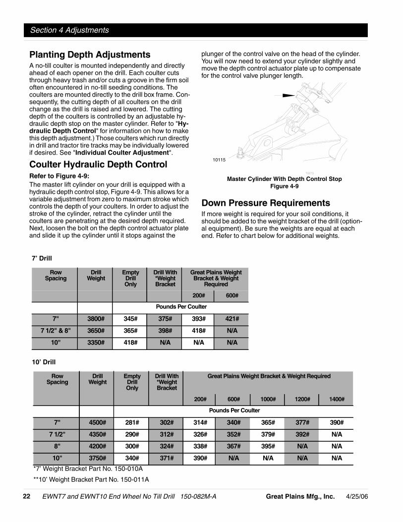
Down Pressure RequirementsIf more weight is required for your soil conditions, itshould be added to the weight bracket of the drill (option-al equipment). Be sure the weights are equal at eachend. Refer to chart below for additional weights.
10115
Master Cylinder With Depth Control StopFigure 4-9
7’ Drill
RowSpacing
DrillWeight
EmptyDrillOnly
Drill With*WeightBracket
Great Plains WeightBracket & Weight
Required
200# 600#
Pounds Per Coulter
7" 3800# 345# 375# 393# 421#
7 1/2" & 8" 3650# 365# 398# 418# N/A
10" 3350# 418# N/A N/A N/A
10’ Drill
RowSpacing
DrillWeight
EmptyDrillOnly
Drill With*WeightBracket
Great Plains Weight Bracket & Weight Required
200# 600# 1000# 1200# 1400#
Pounds Per Coulter
7" 4500# 281# 302# 314# 340# 365# 377# 390#
7 1/2" 4350# 290# 312# 326# 352# 379# 392# N/A
8" 4200# 300# 324# 338# 367# 395# N/A N/A
10" 3750# 340# 371# 390# N/A N/A N/A N/A
*7’ Weight Bracket Part No. 150-010A
**10’ Weight Bracket Part No. 150-011A
-234/25/06 Great Plains Mfg., Inc.
Section 4 Adjustments
EWNT7 and EWNT10 End Wheel No Till Drill 150-082M-A
Individual Opener & CoulterWhen coulters and openers follow in tractor tire tracksand individual coulters do not give satisfactory depth,the coulter mounting bars can be lowered up to 1 1/2" byloosening the mounting clamps and adjusting the coulterand opener to the desired setting. Lowering openers andcoulters will not aid in penetrating hard soil. This isachieved by adding weight to the drill. Refer to "CoulterDown Pressure Requirements". To retighten theclamps, snug the hex head mounting bolts until the u-bolts are tight on each side of the spring bar. Tightennuts on u-bolts and then tighten hex head mountingbolts.
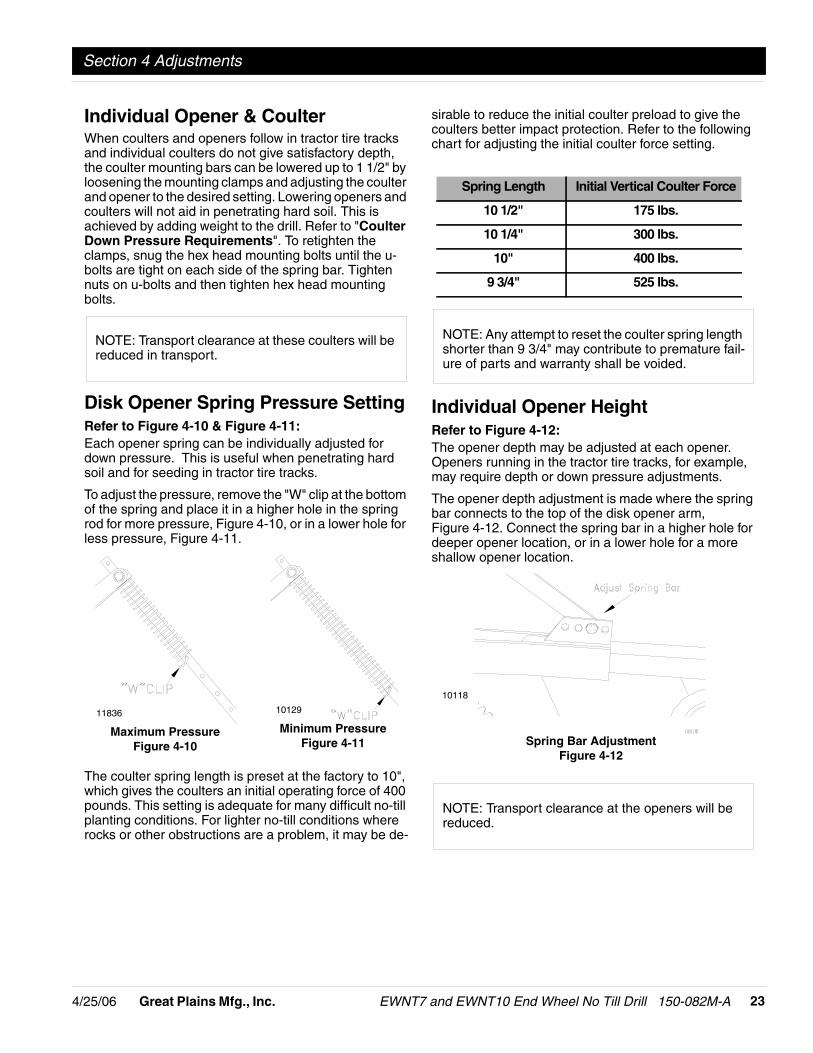
Disk Opener Spring Pressure SettingRefer to Figure 4-10 & Figure 4-11:Each opener spring can be individually adjusted fordown pressure. This is useful when penetrating hardsoil and for seeding in tractor tire tracks.
To adjust the pressure, remove the "W" clip at the bottomof the spring and place it in a higher hole in the springrod for more pressure, Figure 4-10, or in a lower hole forless pressure, Figure 4-11.
The coulter spring length is preset at the factory to 10",which gives the coulters an initial operating force of 400pounds. This setting is adequate for many difficult no-tillplanting conditions. For lighter no-till conditions whererocks or other obstructions are a problem, it may be de-
NOTE: Transport clearance at these coulters will bereduced in transport.
11836 10129
Minimum PressureFigure 4-11
Maximum PressureFigure 4-10
sirable to reduce the initial coulter preload to give thecoulters better impact protection. Refer to the followingchart for adjusting the initial coulter force setting.
Individual Opener HeightRefer to Figure 4-12:The opener depth may be adjusted at each opener.Openers running in the tractor tire tracks, for example,may require depth or down pressure adjustments.
The opener depth adjustment is made where the springbar connects to the top of the disk opener arm,Figure 4-12. Connect the spring bar in a higher hole fordeeper opener location, or in a lower hole for a moreshallow opener location.
Spring Length Initial Vertical Coulter Force
10 1/2" 175 lbs.
10 1/4" 300 lbs.
10" 400 lbs.
9 3/4" 525 lbs.
NOTE: Any attempt to reset the coulter spring lengthshorter than 9 3/4" may contribute to premature fail-ure of parts and warranty shall be voided.
10118
Spring Bar AdjustmentFigure 4-12
NOTE: Transport clearance at the openers will bereduced.
EWNT7 and EWNT10 End Wheel No Till Drill 150-082M-A 4/25/0624 Great Plains Mfg., Inc.
Section 4 Adjustments
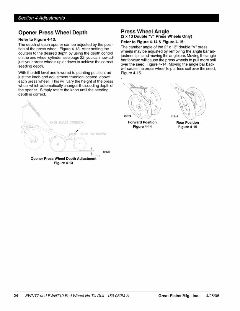
Opener Press Wheel DepthRefer to Figure 4-13:The depth of each opener can be adjusted by the posi-tion of the press wheel, Figure 4-13. After setting thecoulters to the desired depth by using the depth controlon the end wheel cylinder, see page 22, you can now ad-just your press wheels up or down to achieve the correctseeding depth.
With the drill level and lowered to planting position, ad-just the knob and adjustment trunnion located aboveeach press wheel. This will vary the height of the presswheel which automatically changes the seeding depth ofthe opener. Simply rotate the knob until the seedingdepth is correct.
10128
Opener Press Wheel Depth AdjustmentFigure 4-13
Press Wheel Angle(2 x 13 Double "V" Press Wheels Only)Refer to Figure 4-14 & Figure 4-15:The camber angle of the 2" x 13" double "V" presswheels may be adjusted by removing the angle bar ad-justment pin and moving the angle bar. Moving the anglebar forward will cause the press wheels to pull more soilover the seed, Figure 4-14. Moving the angle bar backwill cause the press wheel to pull less soil over the seed,Figure 4-15.
1154410074
Forward PositionFigure 4-14
Rear PositionFigure 4-15

-254/25/06 Great Plains Mfg., Inc.
Section 5 Field Operations
EWNT7 and EWNT10 End Wheel No Till Drill 150-082M-A
Drill Preparations1. Be certain that your rib implement tires are 9.00 x 24
and that they have the proper inflation as listed onpage 6.
2. Load seed box with seed. You should use cleanedseed to get the best results. You should always havethe drill hitched securely to a tractor and lowered be-fore loading.
3. This drill can be transported with a full box of grain.It is best not to do this unless necessary becausethe increased weight does increase the chances forproblems on the road. Do not exceed 20 miles perhour.
4. Your drill comes equipped with an acremeter and itshould be mounted on the right end of the jackshaft.It will accumulate the total acres drilled with the drill.In order to find out the acres covered, write down thebeginning reading and subtract it from the endingreading for the total acres planted.
5. Make sure that the feed cup door adjustment handleon each cup is set the same across the drill.
6. If you notice excessive cracking on large grainseeds, adjust all feed cup door handles to a widersetting. Refer to "Position Seed-Cup Doors" onpage 12.
7. Never back up with openers in ground. If you do,check all openers to be sure none are clogged.
8. This drill is not designed to be turned sharply in thefield. Always lift the drill out of the ground whenturning at ends of field rows and other short-radiusturns.
9. Never allow anyone to ride on the drill.
10. Maximum seeding speed should vary according tosoil conditions.
11. Make sure the drive lockout hub (left end wheel) isengaged, see Figure 3-3 on page 10, to allow thegauge wheel drive to work.
! CAUTION!Escaping fluid under pressure can have sufficient force to pen-etrate the skin. Check all hydraulic lines and hoses before ap-plying pressure. Fluid escaping from a very small hole can bealmost invisible. Use paper or cardboard, not body parts, tocheck for suspected leaks. If injured, seek medical assistancefrom a doctor that is familiar with this type of injury. Foreignfluids in the tissue must be surgically removed within a fewhours or gangrene will result.
Operating ChecklistCheck Reference“Safety Rules” in this Manual “Section 1
Safety Rules” onpage 3
“Hook-Up” & "Operating" instructions in thisManual
“Section 2Assembly
Instructions &Set-Up” on
page 6
“Field Operations” in this Manual “Section 5 FieldOperations” on
page 25
Tire pressure “Tire InflationChart” on
page 6
Feeder Cups for foreign matter
Engage drive hub (left end wheel) “Drive Lock OutHub” onpage 10
Rotate drive (left) wheel to make surethe drive system operates smoothly.
“Drive TrainOperation” on
page 11
Set sprockets to drive type desired. “Change DriveSprockets” on
page 12
Set seed rate. See “SeedingRate” onpage 12.
Fertilizer agitator for foreign matter
Set fertilizer rate See “FertilizerRate” onpage 19.
Disconnect fertilizer drive chain whenfertilizer is not used.
Adjustment of disk opener scrapers forease in rotation.
See “DiskOpener SpringPressure Set-
ting” onpage 23.
Lubricate the drill as needed. See “Lubrica-tion” on
page 26.
Seed & fertilizer tubes
Drill; initially and periodically for loosebolts, pins, and chains.
Section 5 Field Operations

EWNT7 and EWNT10 End Wheel No Till Drill 150-082M-A 4/25/0626 Great Plains Mfg., Inc.
Section 6 Maintenance & Lubrication
4. Feed cup drive sprocket hub should be oiled in itssquare bore. Squirt oil on to the square feed cupshaft and move feed cup adjustment lever back andforth in order to get the oil back into the square. Thisis most important before putting the drill in storage.
5. Store the drill inside if possible for longer drill life.
6. When in storage, lower the drill with openers on aboard or hard surface. Apply a light coat of oil to ex-posed cylinder rods.
Lubrication
Lubrication is required every 50 hours of operation.
Use a multipurpose spray lube. Use as required.Do not over lubricate.
Lubrication Symbols
AsRequired
Seasonally
50
Lubrication is required ____.
Lubrication is required every 10 hours of operation.
10
MaintenanceProper servicing and adjustment is the key to the longlife of any farm implement. With careful and systematicinspection, you can avoid costly maintenance, time andrepair.
1. After using your drill for several hours, check all boltsto be sure they are tight.
2. Adjust idlers to remove excess slack from chains.Clean and use chain lube on all roller chains asneeded.
3. Feed cup drive sprocket should be oiled in its squarebore. Move feed cup adjustment lever away from thesprocket as far as possible in order to get the oil backinto the square.
4. Always maintain the proper air pressure in the ribimplement tires.
5. Disk scrapers should be kept properly adjusted.
6. Replace any worn, damaged or illegible safety de-cals by obtaining new decals from your Great PlainsDealer.
Fertilizer UnitIt is recommended that the fertilizer unit be thoroughlycleaned every two or three days during operating sea-son and before putting the drill in storage for an extend-ed period of time.
Storage1. Clean the drill as necessary. Be sure that the seed
boxes are completely cleaned before storing.
2. Lubricate and adjust all roller chains.
3. Lubricate all pivots as indicated in the following Illus-trations.
NOTE: Fertilizer build up on the rotor will affect thefertilizer application rate. Drop fertilizer tray doors byreleasing latches on back of tray. Using a high-pres-sure water system, thoroughly clean the fertilizertray, gate openings, and rotor. Rotate end sprocketto ensure cleaning the entire fertilizer metering starat each drop location.
Section 6 Maintenance & Lubrication

-274/25/06 Great Plains Mfg., Inc.
Section 6 Maintenance & Lubrication
EWNT7 and EWNT10 End Wheel No Till Drill 150-082M-A
Coulter Arm Pivot
Type of Lubrication: Multipurpose Grease
13880
13877
End Wheel Hub Bearings
Type of Lubrication: Multipurpose Grease
13878
Wheel Arm Pivot Castings
Type of Lubrication: Multipurpose Grease
Seasonally
Coulter Hub Bearings
Type of Lubrication: Multipurpose Grease
13881
Seasonally
8-10
24

EWNT7 and EWNT10 End Wheel No Till Drill 150-082M-A 4/25/0628 Great Plains Mfg., Inc.
Section 6 Maintenance & Lubrication
Clutch Cam
Type of Lubrication: Multipurpose Grease
13881
24Fertilizer Felt Seal
Type of Lubrication: Multipurpose Grease
13882
8
-294/25/06 Great Plains Mfg., Inc.
Section 7 Troubleshooting
EWNT7 and EWNT10 End Wheel No Till Drill 150-082M-A
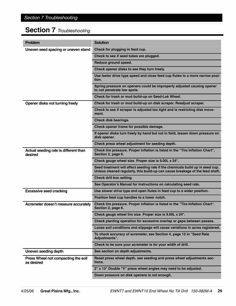
Problem Solution
Uneven seed spacing or uneven stand Check for plugging in feed cup.
Check to see if seed tubes are plugged.
Reduce ground speed.
Check opener disks to see they turn freely.
Use faster drive type speed and close feed cup flutes to a more narrow posi-tion.
Spring pressure on openers could be improperly adjusted causing openerto not penetrate low spots.
Check for trash or mud build-up on Seed-Lok Wheel.
Opener disks not turning freely Check for trash or mud build-up on disk scraper. Readjust scraper.
Check to see if scraper is adjusted too tight and is restricting disk move-ment.
Check disk bearings.
Check opener frame for possible damage.
If opener disks turn freely by hand but not in field, lessen down pressure ondisk opener.
Check press wheel adjustment for seeding depth.
Actual seeding rate is different thandesired
Check tire pressure. Proper inflation is listed in the “Tire Inflation Chart",Section 2, page 6.
Check gauge wheel size. Proper size is 9.00L x 24".
Seed treatment will affect seeding rate if the chemicals build up in seed cup.Unless cleaned regularly, this build-up can cause breakage of the feed shaft.
Check drill box setting.
See Operator’s Manual for instructions on calculating seed rate.
Excessive seed cracking Use slower drive type and open flutes in feed cup to a wider position.
Position feed cup handles to a lower notch.
Acremeter doesn’t measure accurately Check tire pressure. Proper inflation is listed in the "Tire Inflation Chart".Section 2, page 6.
Check gauge wheel tire size. Proper size is 9.00L x 24".
Check planting operation for excessive overlap or gaps between passes.
Loose soil conditions and slippage will cause variations in acres registered.
To check accuracy of acremeter, see Section 4, page 12 in "Seed RateAdjustments".
Check to be sure your acremeter is for your width of drill.
Uneven seeding depth See section on depth adjustments.
Press Wheel not compacting the soilas desired
Reset press wheel depth, see seeding and press wheel adjustments sec-tions.
2" x 13" Double "V" press wheel angles may need to be adjusted.
Down pressure on disk openers is not enough.
Section 7 Troubleshooting

EWNT7 and EWNT10 End Wheel No Till Drill 150-082M-A 4/25/0630 Great Plains Mfg., Inc.
Section 7 Troubleshooting
Grain box not emptying evenly Certain models do not have the same number of seed cups between eachdivider of bulkhead. The section with the larger number of cups will emptysooner.
Press wheel or openers plugging Drilling in damp or wet conditions may increase this problem.
Reduce down pressure on openers.
Do not back up drill in the field, or stop and allow drill to roll backwards withopeners in the ground.
If using double "V" press wheels, adjust angle bar.
Check Seed-Lok Wheel.
Raising and lowering drill is rough oruneven
Lubricate wheel arm pivot casting.
Check hydraulic fittings or leaks.
Rephasing cylinders not properly bled. Refer to "Bleeding the Hydraulic Lift-ing System" on page 9. When raising the drill at the end of the field, the lift-ing cylinders should be fully extended to insure that they are alwaysrephased. If drill is only raised enough to lift openers out of ground, lift cyl-inders may eventually get out of sequence and cause uneven seeding depth.
Feed cup sprockets locked up ortwisted feed drive shaft
Check for foreign matter lodged in one or more feeder cup sprockets.
Liquid insecticide from seed has dried within the feed cups. Remove thebuild up by disassembling each feed cup and scrape the foreign substancefrom the turning surfaces. NOTE: Liquid insecticide should be applied withcaution and care should be taken to clean the feed system after drillingtreated seeds.
Coulters not going deep enough Check weight chart on page 22 and add additional weight.
Lower coulter spring bars on tool bar. {Only in tire tracks.}
Check cylinder depth stop, refer to page 22.
Coulters and drill going to deep Check weight chart on page 22 and remove weight if necessary.
Set press wheels to a shallower depth.
Check cylinder depth stop, refer to page 22.
Hoses plugging in no-till conditions Drill at a slight angle to the rows.
Problem Solution

-314/25/06 Great Plains Mfg., Inc.
Section 8 Specifications & Warranty
EWNT7 and EWNT10 End Wheel No Till Drill 150-082M-A
Section 8 Specifications & Warranty
7’ End Wheel No-Till 10’ End Wheel No-Till
Transport Width 9’ 8" 12’ 6"
Tire Size: 9.00 x 24 9.00 x 24
Box Capacity: 17.1 Bushels 23.75 Bushels
Fertilizer Attachment Capacity: 553 Pounds 741 Pounds
Seed Capacity of Fertilizer/Native Grass Box: 12.7 Bushels 17 Bushels
7’ End Wheel No-TillDrill Row Spacing No. Of Openers Drill Weight
7" 11 *3800
7 1/2" & 8" 10 *3650#
10" 8 *3350#
*Approximate weights for machines equipped with double disk openers, 2" x13" single press wheels, step and hydraulic cylinders.
10’ End Wheel No-TillDrill Row Spacing No. Of Openers Drill Weight
7" 16 *4500#
7 1/2" 15 *4350#
8" 14 *4200#
10" 11 *3750#
10122
NOTE: All tires are warranted by the origi-nal manufacturer of the tire. Tire warrantyinformation can be found in the brochuresincluded with your Operator’s and PartsManuals or online at the manufacturer’swebsites. For service assistance or infor-mation, contact your nearest AuthorizedFarm Tire Retailer.
Manufacturer WebsiteTitan www.titan-intl.comGoodyear www.goodyearag.comFirestone www.firestoneag.com

EWNT7 and EWNT10 End Wheel No Till Drill 150-082M-A 4/25/0632 Great Plains Mfg., Inc.
Section 8 Specifications & Warranty
WarrantyGreat Plains Manufacturing, Incorporated warrants to the original pur-chaser that this seeding equipment will be free from defects in materialand workmanship for a period of one year from the date of original pur-chase when used as intended and under normal service and conditionsfor personal use; 90 days for commercial or rental purposes. This War-ranty is limited to the replacement of any defective part by Great PlainsManufacturing, Incorporated and the installation by the dealer of anysuch replacement part. Great Plains reserves the right to inspect anyequipment or part which are claimed to have been defective in materialor workmanship.This Warranty does not apply to any part or product which in GreatPlains’ judgement shall have been misused or damaged by accident orlack of normal maintenance or care, or which has been repaired or al-tered in a way which adversely affects its performance or reliability, orwhich has been used for a purpose for which the product is not de-signed. This Warranty shall not apply if the product is towed at a speedin excess of 20 miles per hour.Claims under this Warranty must be made to the dealer which originallysold the product and all warranty adjustments must by made throughsuch dealer. Great Plains reserves the right to make changes in mate-rials or design of the product at any time without notice.This Warranty shall not be interpreted to render Great Plains liable fordamages of any kind, direct, consequential, or contingent, to property.Furthermore, Great Plains shall not be liable for damages resulting fromany cause beyond its reasonable control. This Warranty does not ex-tend to loss of crops, losses caused by harvest delays or any expenseor loss for labor, supplies, rental machinery or for any other reason.No other warranty of any kind whatsoever, express or implied, ismade with respect to this sale; and all implied warranties of mer-chantability and fitness for a particular purpose which exceedthe obligations set forth in this written warranty are hereby dis-claimed and excluded from this sale.This Warranty is not valid unless registered with Great Plains Manufac-turing, Incorporated within 10 days from the date of original purchase.