Operator’s Manual Fifth Editionmanuals.gogenielift.com/Operators/english/33887.pdf · 6 Genie AWP...
24
Transcript of Operator’s Manual Fifth Editionmanuals.gogenielift.com/Operators/english/33887.pdf · 6 Genie AWP...

Genie AWP Part No. 33887
Operator’s Manual Fifth Edition
Important
Read, understand and obey these safety rules andoperating instructions before operating this machine.Only trained and authorized personnel shall bepermitted to operate this machine. This manual shouldbe considered a permanent part of your machine andshould remain with the machine at all times. If youhave any questions, call Genie Industries.
Contents
PageSafety Rules .............................................................. 1Controls ..................................................................... 6Legend ...................................................................... 7Pre-operation Inspection ........................................... 8Function Tests .......................................................... 10Workplace Inspection ............................................... 12Operating Instructions .............................................. 13Battery and Charger Instructions .............................. 14Transport Instructions ............................................... 16Tilt-back Operation Instructions ................................ 18Decals ...................................................................... 20Specifications ........................................................... 23
Genie North AmericaTelephone (206) 881-1800Toll Free 800 536-1800 in U.S.A.Toll Free 800 426-8089 in CanadaFax (206) 883-3475
Genie EuropeTelephone (44) 01636-605030Fax (44) 01636-611090
®
Copyright © 1993 by Genie Industries
Third Edition: First Printing, March 1993Second Printing, June 1994
Fourth Edition: First Printing, July 1994Second Printing, October 1994
Fifth Edition: First Printing, January 1995
Genie® is a registered trademarkof Genie Industries
Registered 2009987
U.S.A. Patent No. 5,121,816U.S.A. Patent No. 5,105,913
Printed on recycled paper
Printed in U.S.A.
®

Part No. 33887 Genie AWP 1
Operator’s ManualFifth Edition
Safety Rules
Danger
Failure to obey the instructions andsafety rules in this manual willcause death or serious injury.
Do Not Operate Unless:
You learn and practice the principles of safemachine operation contained in this operator'smanual.
1 Avoid hazardous situations.
Know and understand the above principlebefore going on to the next section.
2 Always perform a pre-operation inspection.
3 Always perform the function tests prior touse.
4 Inspect the work place.
5 Only use the machine as a personnel lift.
You read, understand and obey:
- manufacturer’s instructions andsafety rules—operator’s manual andmachine decals
- employer’s safety rules and worksiteregulations
- applicable governmental regulations
The first time this machine is set up for use, abreather cap is installed (see Breather Cap,page 8).
2 Genie AWP Part No. 33887
Operator’s Manual Fifth Edition
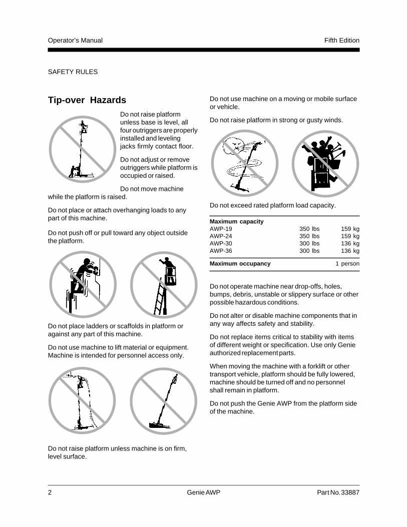
Tip-over HazardsDo not raise platformunless base is level, allfour outriggers are properlyinstalled and levelingjacks firmly contact floor.
Do not adjust or removeoutriggers while platform isoccupied or raised.
Do not move machinewhile the platform is raised.
Do not place or attach overhanging loads to anypart of this machine.
Do not push off or pull toward any object outsidethe platform.
Do not place ladders or scaffolds in platform oragainst any part of this machine.
Do not use machine to lift material or equipment.Machine is intended for personnel access only.
Do not raise platform unless machine is on firm,level surface.
Do not use machine on a moving or mobile surfaceor vehicle.
Do not raise platform in strong or gusty winds.
Do not exceed rated platform load capacity.
Maximum capacityAWP-19 350 lbs 159 kgAWP-24 350 lbs 159 kgAWP-30 300 lbs 136 kgAWP-36 300 lbs 136 kg
Maximum occupancy 1 person
Do not operate machine near drop-offs, holes,bumps, debris, unstable or slippery surface or otherpossible hazardous conditions.
Do not alter or disable machine components that inany way affects safety and stability.
Do not replace items critical to stability with itemsof different weight or specification. Use only Genieauthorized replacement parts.
When moving the machine with a forklift or othertransport vehicle, platform should be fully lowered,machine should be turned off and no personnelshall remain in platform.
Do not push the Genie AWP from the platform sideof the machine.
SAFETY RULES
Part No. 33887 Genie AWP 3
Operator’s ManualFifth Edition
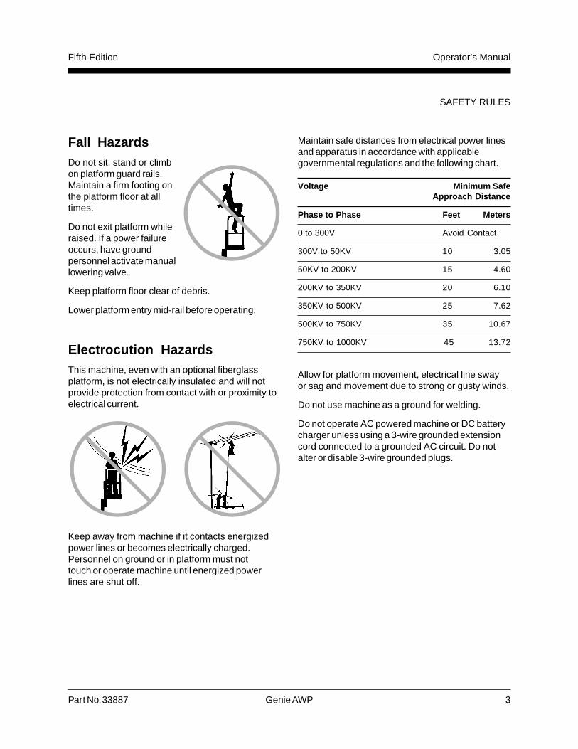
Fall HazardsDo not sit, stand or climbon platform guard rails.Maintain a firm footing onthe platform floor at alltimes.
Do not exit platform whileraised. If a power failureoccurs, have groundpersonnel activate manuallowering valve.
Keep platform floor clear of debris.
Lower platform entry mid-rail before operating.
Electrocution HazardsThis machine, even with an optional fiberglassplatform, is not electrically insulated and will notprovide protection from contact with or proximity toelectrical current.
Keep away from machine if it contacts energizedpower lines or becomes electrically charged.Personnel on ground or in platform must nottouch or operate machine until energized powerlines are shut off.
SAFETY RULES
Maintain safe distances from electrical power linesand apparatus in accordance with applicablegovernmental regulations and the following chart.
Voltage Minimum SafeApproach Distance
Phase to Phase Feet Meters
0 to 300V Avoid Contact
300V to 50KV 10 3.05
50KV to 200KV 15 4.60
200KV to 350KV 20 6.10
350KV to 500KV 25 7.62
500KV to 750KV 35 10.67
750KV to 1000KV 45 13.72
Allow for platform movement, electrical line swayor sag and movement due to strong or gusty winds.
Do not use machine as a ground for welding.
Do not operate AC powered machine or DC batterycharger unless using a 3-wire grounded extensioncord connected to a grounded AC circuit. Do notalter or disable 3-wire grounded plugs.

4 Genie AWP Part No. 33887
Operator’s Manual Fifth Edition
®
1 Outrigger interlock displaylights (four)
2 Key switch
3 Emergency stop button
4 Power light
5 Control activate button
6 Up/Down switch
Controls
Ground Controls
Platform Controls
3
5
6
3
2
1
4

Part No. 33887 Genie AWP 5
Operator’s ManualFifth Edition
Legend
6 11 6 9 8 7 67 10
16
13
3
4
1
2
5
7 66 107 20 106
24
22
21
23
25
17
26
7
Model shown is aGenie AWP-36 and isrepresentative of all AWPmodels.
1 Fuse(s)
2 AC power supply cord
3 Ground controls
4 Hydraulic power unit
5 Manual lowering valve
6 Outrigger with leveling jack
7 Base outrigger socket
8 Bubble level
15
14
12
6
9
13
18
19
17
9 Base
10 Transport tie down
11 Sliding T-handle
12 Operator's manualstorage container
13 Platform
14 Platform entry mid-rail
15 AC outlet
16 Platform controls
17 Mast
18 Outrigger storage socket
19 Battery charger (DCmodels)
20 Forklift pocket
21 Loading pivot bar
22 Battery pack (DC models)
23 Loading stop bracket
24 Retaining pin*
25 Tilt-back frame*
26 Tilt-back strut*
* Tilt-back frame is standard onAWP-30 and 36, and optionalon AWP 19 and 24.

6 Genie AWP Part No. 33887
Operator’s Manual Fifth Edition
Pre-operation Inspection
Do Not Operate Unless:
You learn and practice the principles of safemachine operation contained in this operator’smanual.
1 Avoid hazardous situations.
2 Always perform a pre-operation inspection.
Know and understand the above principlebefore going on to the next section.
3 Always perform the function tests prior to use.
4 Inspect the work place.
5 Only use the machine as a personnel lift.
Fundamentals
The Pre-operation Inspection is a visual inspectionperformed by the operator prior to each work shift.This inspection is designed to discover if anythingis apparently wrong with a machine before theoperator tests it.
Inspect the machine for modifications, damage orloose or missing parts.
A damaged or modified machine must never beused. If damage or any variation from factorydelivered condition is discovered, the machinemust be tagged and removed from service.
Repairs to the machine may only be made by aqualified service technician, according to themanufacturer's specifications. After repairs arecompleted, the operator must perform a pre-operation inspection again before testing functions.
Breather CapComponent damage will occur if the machineis operated without a breather cap.
The first time thismachine is set up foruse, the pipe plug in thehydraulic reservoirshould be removed andpermanently replacedwith a breather cap.
A breather cap is supplied and can be foundin an envelope taped to the mast near theplatform controls.
Part No. 33887 Genie AWP 7
Operator’s ManualFifth Edition
PRE-OPERATION INSPECTION
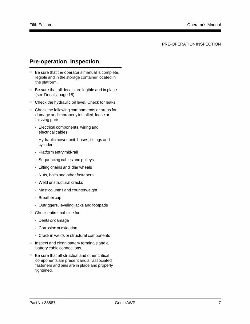
Pre-operation Inspection
Be sure that the operator’s manual is complete,legible and in the storage container located inthe platform.
Be sure that all decals are legible and in place(see Decals, page 18).
Check the hydraulic oil level. Check for leaks.
Check the following compomemts or areas fordamage and improperly installed, loose ormissing parts:
· Electrical components, wiring andelectrical cables
· Hydraulic power unit, hoses, fittings andcylinder
· Platform entry mid-rail
· Sequencing cables and pulleys
· Lifting chains and idler wheels
· Nuts, bolts and other fasteners
· Weld or structural cracks
· Mast columns and counterweight
· Breather cap
· Outriggers, leveling jacks and footpads
Check entire mahcine for:
· Dents or damage
· Corrosion or oxidation
· Crack in welds or structural components
Inspect and clean battery terminals and allbattery cable connections.
Be sure that all structual and other criticalcomponents are present and all associatedfasteners and pins are in place and properlytightened.
8 Genie AWP Part No. 33887
Operator’s Manual Fifth Edition
Function Tests
Do Not Operate Unless:
You learn and practice the principles of safemachine operation contained in this operator’smanual.
1 Avoid hazardous situations.
2 Always perform a pre-operation inspection.
3 Always perform the function tests prior touse.
Know and understand the above principlebefore going on to the next section.
4 Inspect the work place.
5 Only use the machine as a personnel lift.
You read, understand and obey:
- manufacturer’s instructions andsafety rules—operator’s manual andmachine decals
- employer’s safety rules and worksiteregulations
- applicable governmental regulations
The first time this machine is set up for use, abreather cap is installed (see Breather Cap,page 8).
Fundamentals
The Function Tests are designed to discover anymalfunctions before the machine is put into service.The operator must follow the step-by-stepinstructions to test all machine functions.
A malfunctioning machine must never be used. Ifmalfunctions are discovered, the machine must betagged and remoed from service. Repairs to themachine may only be made by a qualified servicetechnician, according to the manufacturersspecifications.
After repairs are completed, the operator mustperform a pre-operation inspection and functiontests before putting the machine into service.

Part No. 33887 Genie AWP 9
Operator’s ManualFifth Edition
Function Tests
1 Select a test area free of obstructions.
2 Connect appropriate power source.
3 Turn the key switch to the ON position.
Result: The power light should come on.
4 Pull out the red Emergency Stop button tothe ON position.
5 Select an outriggerand slide it into abase socket until theoutrigger lock pinsnaps into place.Bring the outriggerleveling jack into firmcontact with ground.
6 Check the interlockdisplay lights at theground controls.Confirm that thecorresponding lightis on.
7 Repeat procedure foreach of the remainingoutriggers.
Test Emergency Stop
8 Use the bubble level and adjust leveling jacksuntil the machine base is level.
9 Twist to release the red Emergency Stop buttonat the platform controls.
10 Push in the red Emergency Stop button at theground controls to the OFF position.
FUNCTION TESTS
11 Push in the control activate button and rotatethe up/down switch in the direction of intendedtravel.
Result: Up/Downfunctions should notoperate.
12 Push in the redEmergency Stopbutton at the platformcontrols to the OFF
position.
13 Pull out the red Emergency Stop button at theground controls to the ON position.
14 Push in the control activate button and rotatethe up/down switch in the direction of intendedtravel.
Result: Up/Down functions should not operate.
Test Outrigger Interlock
15 Twist to release the red Emergency Stop buttonat the platform controls.
16 Pull out the red Emergency Stop button at theground controls to the ON position.
Result: Up/Down functions should operate.
17 Unscrew one leveling jack until thecorresponding interlock display light turns off.
Result: Up/Down functions should not operate.
18 Return the leveling jack to previous setting andcheck the bubble level.
19 Repeat procedure for each outrigger.
Test Manual Lowering
20 Raise platform slightly.
21 Activate the manual lowering valve located onthe hydraulic power unit.
Result: Platform should descend.

10 Genie AWP Part No. 33887
Operator’s Manual Fifth Edition
Work Place Inspection
Do Not Operate Unless:
You learn and practice the principles of safemachine operation contained in this operator’smanual.
1 Avoid hazardous situations.
2 Always perform a pre-operationinspection.
3 Always perform function tests prior to use.
4 Inspect the work place.
Know and understand the above principlesbefore going on to the next section.
5 Only use the machine as it was intended.
Fundamentals
The Work Place Inspection helps the operatordetermine if the work place is suitable for safemachine operation. It should be performed by theoperator prior to moving the machine to the workplace.
It is the operator’s responsibility to read andremember the work place hazards, then watch forand avoid them while moving, setting up andoperating the machine.
Work Place Inspection
Be aware of and avoid the following hazardoussituations:
· drop-offs or holes
· bumps, floor obstructions or debris
· overhead obstructions and high voltageconductors
· hazardous locations
· inadequate surface support to withstand all loadforces imposed by the machine
· wind and weather conditions
· the presence of unauthorized personnel
· other possible unsafe conditions

Part No. 33887 Genie AWP 11
Operator’s ManualFifth Edition
Operating Instructions
Do Not Operate Unless:
You learn and practice the principles of safemachine operation contained in this operator’smanual.
1 Avoid hazardous situations.
2 Always perform a pre-operationinspection.
3 Always perform function tests prior to use.
4 Inspect the work place.
5 Only use the machine as a personnel lift.
FundamentalsUsing the machine for anything other than liftingmaterial is unsafe.
If more than one operator is expected to use amachine at different times in the same work shift,each operator is expected to follow all safety rulesand instructions in the operator’s manual. Thatmeans every new operator should perform a pre-operation inspection, function tests and a workplace inspection before using the machine.
Setup1 Position machine on a firm, level surface
directly below desired work area.
2 Connect to appropriate power source:DC models: Connect battery pack.AC models: Connect to a grounded 15A ACpower supply. Use a 12 gauge (3.3mm2) 3-wiregrounded extension cord no longer than50 feet (13m).
3 Insert key and turn to the ON position.
4 Pull out the red Emergency Stop button and besure the power light is on.
5 Install outriggers and adjust to level the machineand raise base casters slightly off the ground.
6 Check the interlock display. Be sure that all fourinterlock display lights are on.
Emergency Stop
Push in the red Emergency Stop button at platform
controls or at groundcontrols to stop allfunctions.
ManualLowering
1 Activated from ground only.
2 Activate manual lowering valve located onhydraulic power unit to lower platform.
Emergency Stop
Control Activate
Up/Down Switch

12 Genie AWP Part No. 33887
Operator’s Manual Fifth Edition
Platform Raise and Lower
1 Follow Setup procedure.
2 Twist to release the red Emergency Stop button.
3 Push in control activate button and rotate the
up/down switch inthe desired directionof travel.
After Each Use
1 Select a safestorage location—firm, level surface,weather protected, clear of obstruction andtraffic.
2 Chock wheels to prevent machine from rolling.
3 Remove key to secure from unauthorized use.
4 DC models: Disconnect battery pack andrecharge battery.
OPERATING INSTRUCTIONS
Battery and Charger Instructions
Observe and Obey:
Do not use external charger or booster battery.
Charge battery in a well-ventilated area.
Use proper AC input voltage for charging asindicated on charger.
Use only Genie authorized battery and charger.CSA applicable model:Manual Lester charger 06685 or 06670Automatic Lester charger 15840-90

Part No. 33887 Genie AWP 13
Operator’s ManualFifth Edition
OPERATING INSTRUCTIONS
battery is fully charged and the battery chargershould be turned off.
8 Disconnect the AC supply.
9 Check the battery acid level when the chargingcycle is completed. Replenish with water to thebottom of the fill tube.
Dry Battery Filling andCharging Instructions
1 Remove battery vent caps and permanentlyremove plastic seal from battery vent openings.
2 Fill each cell with battery acid (electrolyte) untillevel is sufficient to cover plates.
Do not fill to maximum level until battery chargecycle is complete. Overfilling can cause the batteryacid to overflow during charging. Neutralize batteryacid spills with baking soda and water.
3 Install the vent caps.
4 Charge the battery.
5 Check the battery acid level when the chargingcycle is complete. Replenish with water to thebottom of the fill tube.
Style A Style B
To Charge Battery1 Manual charger models: Disconnect the
battery pack from the machine.
2 Open battery pack lid to access battery.
3 Remove the battery vent caps and checkthe battery acid level. If necessary, add onlyenough water to cover the plates. Do not overfillprior to charging cycle.
4 Replace the vent caps.
Style A models: Battery pack lid must remainopen during entire charging cycle.
Style B models: Battery pack lid can remainopen or closed during the charging cycle.
5 Connect the battery charger to groundedAC circuit.
6 Automatic charger models: Set the powerswitch to the AUTO position. Charger will startafter a short delay.
Manual Charger models: Set the timer basedon the amount of use:
Light use—less than 15 lifting cycles: Set to 7hours.
Heavy use—greater than 15 lifting cycles: Set toON position.
7 All models: The charger will automatically shutoff at end of the set period.
Manual charger models: If ampere meter dropsto 3A or less within the first 15 minutes, the

14 Genie AWP Part No. 33887
Operator’s Manual Fifth Edition
OPERATING INSTRUCTIONS
Transport Instructions
Observe and Obey:
Be sure vehicle capacity and loading surfacesare sufficient to support machine weight (seeSpecifications, page 21). Some pick-up trucktailgates are not strong enough to support theweight of the machine and may requirereinforcement.
Do not load machine onto a vehicle unless it isparked on a level surface.
Transport vehicle must be secured to preventrolling while machine is being loaded.
Lifting force needed to tilt machine ontotransport vehicle requires two people.
Machine must be securely fastened to transportvehicle.
Be sure to lock both swivel casters on tilt-backframe.
Do not transport with the tilt-back frame in thelowered position. Tilt-back frame is standard onAWP-30 and 36, and optional on AWP-19 and24.
Loading for Transport1 Fully lower platform.
2 Push in red Emergency Stop buttons, turn keyswitch to the OFF position and remove key.
3 Remove outriggers from base and place instorage sockets.
4 DC models: Disconnect battery cable andremove battery pack.
5 Inspect entire machine for loose or unsecureditems.
6 Slide the stop bracket to the top lock position.
Genie AWP-19 & 24 without tilt-back frame
All models with tilt-back frame

Part No. 33887 Genie AWP 15
Operator’s ManualFifth Edition
OPERATING INSTRUCTIONS
6 Hook loading pivot to stop bracket.
7 Position machine flush against loading surface.Lower and lock stop bracket to the lowest lockpin position above loading surface.
8 All models with tilt-back frames:
Be sure both stop bracket lock pins are fullyengaged.
Be sure both tilt-back frame swivel casters arelocked.
9 Slide out T-handle until lock pin snaps intoplace.
10 Two people should lift T-handle to tilt machineonto loading surface.
11 Carefully push machine into transport position.
12 Return sliding T-handle to stowed position.
13 Secure the machine base and mast to thetransport vehicle. Use chains or straps of ampleload capacity.
14 Reverse procedure to unload.
16 Genie AWP Part No. 33887
Operator’s Manual Fifth Edition
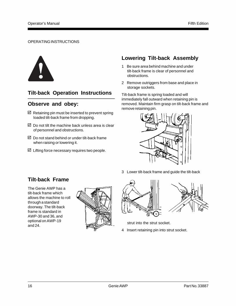
Lowering Tilt-back Assembly1 Be sure area behind machine and under
tilt-back frame is clear of personnel andobstructions.
2 Remove outriggers from base and place instorage sockets.
Tilt-back frame is spring loaded and willimmediately fall outward when retaining pin isremoved. Maintain firm grasp on tilt-back frame andremove retaining pin.
3 Lower tilt-back frame and guide the tilt-back
strut into the strut socket.
4 Insert retaining pin into strut socket.
Tilt-back Operation Instructions
Observe and obey:
Retaining pin must be inserted to prevent springloaded tilt-back frame from dropping.
Do not tilt the machine back unless area is clearof personnel and obstructions.
Do not stand behind or under tilt-back framewhen raising or lowering it.
Lifting force necessary requires two people.
OPERATING INSTRUCTIONS
Tilt-back Frame
The Genie AWP has atilt-back frame whichallows the machine to rollthrough a standarddoorway. The tilt-backframe is standard inAWP-30 and 36, andoptional on AWP-19and 24.

Part No. 33887 Genie AWP 17
Operator’s ManualFifth Edition
Tilting backMachine
1 Slide out T-handleuntil lock pin snapsinto place.
2 Two people should liftthe machine with theT-handle tomid-tilt position—casters on tilt-back framecontact floor, and machine supported byextended tilt-back strut.
3 Continue lifting until telescoping tilt-back strut iscompletely compressed.
Returning Machine ToStanding Position
1 Be sure area below machine base andT-handle is clear of personnel and obstructions.
2 Carefully pull down T-handle until machine restsat mid-tilt position.
3 Two people shouldlower the machine withthe T-handle until basecasters are in contactwith ground.
4 Return slidingT-handle to stowedposition.
Stowing Tilt-back Assembly
1 Remove retaining pin.
2 Firmly grasp tilt-back frame and removetilt-back strut fromstrut socket.
3 Lift tilt-back frame,hold in uprightposition againstspring and securewith retaining pin.
OPERATING INSTRUCTIONS

18 Genie AWP Part No. 33887
Operator’s Manual Fifth Edition
DecalsIn
dex Part No. Quantity
Decal Description
1 31237 1Notice - Before Each Work Shift
2 31243 1Danger - General Safety
3 31071 1Warning - Failure to Read/Obey Manual
4 31072 1Label - Operator's Manual Storage Container
5 33597 1Label - Fuses (AC models only)
6 31074 1Label - ANSI/Patents
7 33598 1Label - Interlock Display
8 27845 1Notice - Manual Lowering LeverCaution - Collision Hazard (descending platform)or32986 1Notice - Manual Lowering KnobCaution - Collision Hazard (descending platform)
9 31245 1Warning - Collision Hazard (runaway lift)
10 31076 1Caution - 8A Maximum, 115V AC
11 28157 1Notice - Dexron
12 27857 1Caution - Pipe Plug
13 1699 —Safety Tape
14 27865 1Label - Bubble Level
15 27863 3Caution - Component Damage Hazard
16 27839 1Label - Sliding T-handle
Ind
ex Part No. QuantityDecal Description
17 31311 2Label - AWP-19or31312 2Label - AWP-24or31452 2Label - AWP-30or31453 2Label - AWP-36
18 31067 1Notice - Operating Instructions
19 31069 (AWP-19 & 24 models only) 1Notice - maximum Capacity 350 lbsor27870 (AWP-30 & 36 models only) 1Notice - Maximum Capacity, 300 lbs.
20 27872 1Danger - Tip-over Hazard (outriggers)
21 27841 1Label - Stop Bracket
22 27842 1Label - Loading Pivot
23 27864 1Notice - Lower Stop Bracket before ...
24 27868 1Danger - Relief Valve
25 27867 2Label - Swivel Lock
26 27873 1Notice - Maintain firm grasp on ...
27 27844 1Label - Strut Socket
28 27840 1Label - Retaining Pin
29 27843 1Label - Tilt-back Strut

Part No. 33887 Genie AWP 19
Operator’s ManualFifth Edition
DECALS
43 5
14
19
1
2
18
15
16
15
12
11
10
9
8
24
23
15
22
20
21
Part No. QuantityDecal Description
30 27838 1Warning - Tilt-back HazardsNotice - Tilt-back Instructions
31 27874 1Label - Insert retaining pin into ...
32 31070 1Danger - Tip-over Hazard (moving machine)
33 31068 1Danger - Battery SafetyNotice - Battery Charger Instructions
34 28372 1Caution - Quick Disconnect
35 28398 1Danger - Battery Safety (manual charger)
36 27856 1Caution - Component Damage (manual charger)
37 27853 1Notice - Battery Charger Instructions
13
17
Ind
ex
32
1
2
3
Fiberglass Platform Option
6 7
AWP-19 & 24 without Tilt-back Frame

20 Genie AWP Part No. 33887
Operator’s Manual Fifth Edition
DECALS
All Models with Tilt-back Frame
5 6
14
4
1
2
19
3
15
16
18
7
8
9
10
12
10
20
26
21
28
22
15
25
13
15
17
28
24
32
29
30
31
Battery Pack - AutomaticCharger
Battery Pack - Manual Charger
35
36
37 *
*This decal is visible when battery pack cover israised.
33
34
Tilt-back frame is standard on AWP 30 and 36, and optionalon AWP-19 and 24.

Part No. 33887 Genie AWP 21
Operator’s ManualFifth Edition
Model AWP-19 AWP-24 AWP-30 AWP-36
Height, working maximum 25 ft 6 in 30 ft 36 ft 42 ft7.8 m 9.1 m 11.0 m 12.8 m
Height, platform maximum 19 ft 6 in 24 ft 30 ft 36 ft5.9 m 7.3 m 9.1 m 11.0 m
Lift capacity 350 lbs 350 lbs 300 lbs 300 lbs159 kg 159 kg 136 kg 136 kg
Power sourceDC model 12V 12V 12V 12VAC model 110V or 220V 110V or 220V 110V or 220V 110V or 220V
Machine weight 694 / 623 lbs 717 / 639 lbs 866 / 788 lbs 940 / 868 lbs(DC / AC models) 315 / 283 kg 325 / 290 kg 393 / 357 kg 426 / 394 kg
Height, stowed 79 in 79 in 93 in 112 in200 cm 200 cm 236 cm 284 cm
Width 29 in 29 in 29 in 29 in74 cm 74 cm 74c m 74 cm
Length 47.5 in 47.5 in 51.5 in 51.5 in120.6 cm 120.6 cm 130.8 cm 130.8 cm
Platform length 26 in 26 in 26 in 26 in66 cm 66 cm 66 cm 66 cm
Platform width 26 in 26in 26 in 26 in66 cm 66 cm 66 cm 66 cm
Platform height 43 in 43 in 43 in 43 in106 cm 106 cm 106 cm 106 cm
Outrigger footprint 65 x 58 in 65 x 58 in 75 x 73 in 81 x 81 in164 x 146.5 cm 164 x 146.5 cm 190.5 x 185.5 cm 205 x 205 cm
Continuous improvement of our products is a Geniepolicy. Product specifications are subject to changewithout notice or obligation.
Specifications

EuropeBrunel Drive
Newark
Nottinghamshire
NG24 2EG England
U.S.A.18340 NE 76th Street
P.O. Box 69
Redmond, Washington
98073-0069