OPERATOR MANUAL - Scivena Scientific M2300-M2350...1 OPERATOR MANUAL Wall Mount Anesthesia Machines...
25
1 OPERATOR MANUAL Wall Mount Anesthesia Machines Models: M2300, M2350, M2500, M2550 (Shown with optional equipment) 12330 SE Hwy 212 Clackamas, Oregon 97015 (503) 822-1157 Local and International – Toll Free 877-615-5632 [email protected] – www.scivenascientific.com M2300 M2550 M2350 M2500
Transcript of OPERATOR MANUAL - Scivena Scientific M2300-M2350...1 OPERATOR MANUAL Wall Mount Anesthesia Machines...

1
OPERATOR MANUAL
Wall Mount Anesthesia Machines Models: M2300, M2350, M2500, M2550
(Shown with optional equipment)
12330 SE Hwy 212 Clackamas, Oregon 97015
(503) 822-1157 Local and International – Toll Free 877-615-5632
[email protected] – www.scivenascientific.com
M2300
M2550 M2350
M2500

2
Table of Contents:
Page 3……… Product Examination and Preparation for Use
Page 4……… Machine Diagrams and Part Numbers
Page 5…….... Mounting Instructions
Page 6……….Machine Set-Up Instructions
Page 7 - 22… Accessory Options:
Multi-Station Manifolds – 8, 9
Induction Chambers – 10, 11
Breathing Circuit – 12 - 14
Rodent Heated Surgical Station with Downdraft – 15, 16
Multi-Station Surgical Board – 17, 18
Waste Gas Interfaces – 19 - 22
Page 23……..Warranty / Return Policy
Page 24……..Shipping Policy
Page 25……..Documentation
3
Examination and Preparation for Use
Thank you for ordering a Scivena Scientific Anesthesia Innovations anesthesia machine!
We are delighted to have you as a Scivena Scientific Anesthesia Innovations customer and want you to be completely satisfied with your purchase. Please inspect the contents of your order to see if everything is as you expected. Should anything not be exactly right or if anything was damaged in shipping, please contact your sales representative right away for help.
Our goal is to make your new anesthesia machine as easy to use and care for as possible.
This device is meant to be operated under the normal surveillance and control of a veterinarian trained in its use. However, you need to know more about this device than just how to operate it.
Please read this manual in its entirety before using the Anesthesia Machine!
If you have any comments or questions, we welcome the opportunity to address them. Please contact us directly at 877–615-5632.
Thank you!
Brian Lawson President, Scivena Scientific Anesthesia Innovations
Designed and Manufactured With Pride In Oregon, USA

4
Machine Diagram:
A. Wall Bracket
B. Articulating Arm Assembly
C. Accessory Basket (M2350 and M2550 ONLY)
D. Main Flow Meter- Indicates precise amount of carrier gas entering the system.
E. Flow Control Knob- adjusts precise amount of carrier gas entering the anesthesia machine.
F. Flush Valve- flushes pure carrier gas (bypasses the vaporizer) through the system. Flow
restricted to 30 LPM for subject safety.
G. Optional: Vaporizer- vaporizes the anesthetic agent from a liquid to a gaseous state. Delivers
anesthetic agent at precise percentage concentration independent of temperature and flow
rate. New Tec 3 (p/n VAP3000 Isoflurane, p/n VAP3100 Sevoflurane).
H. Rebreathing Head with Safety Pop-Off Valve and CO2 absorbent canister (M2300 and M2500
ONLY).
I. Common Gas Outlet with 15mm female adaptor. Port through which carrier and anesthetic
gas mixture is delivered through the anesthesia system. (See page 14-17 for induction
chamber and breathing circuit options).
J. Carrier Gas Connection (O2, Med Air or other) - DISS male thread – located on the back of the Main Flow Meter.
M2300
M2550 M2350
M2500
A
B
B
A
E
D
F
C
A
A D
E F
G
G
H
I
I
J
J

5
Mounting Instructions
The M2300 should be mounting into a solid wall stud or back board.
The mounting holes are on 16” centers (standard wall stud distance). o Use lag screws (5/16” or 3/8”) to mount to the wall.
6
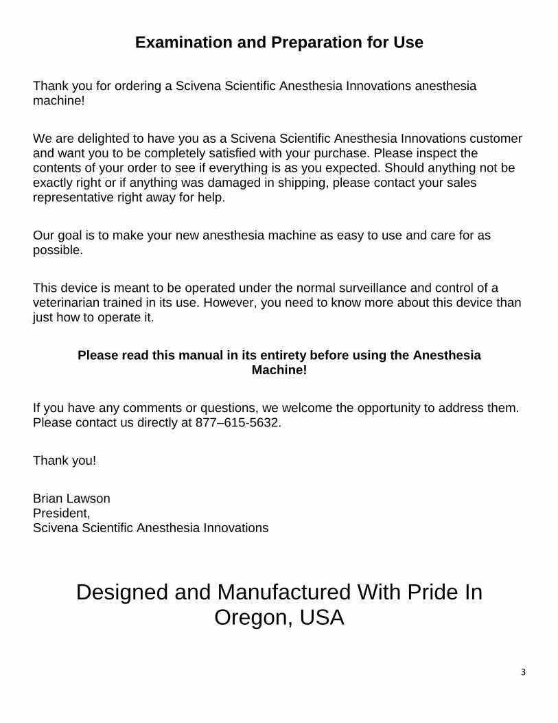
Machine Set Up:
1. Make sure machines are mounted correctly.
2. Connect selected carrier gas hose to DISS male thread connection on back of
the machine (J) and connect hose to carrier gas supply.
a. Common carrier gases include Oxygen (O2), Medical Air (Med Air), and
other combinations of gases.
**CAUTION! NEVER USE PETROLEUM PRODUCTS ON OR NEAR THE
CARRIER GAS SUPPLY WHEN USING OXYGEN AS THE CARRIER GAS!
3. Connect any optional accessories (see pages 7-22).
4. Connect waste anesthetic gas management system.
5. Fill vaporizer with appropriate anesthetic agent.
6. Make sure carrier gas supply is on.
M2300/M2350/M2500/M2550 is now ready for use

7
OPTIONAL ACCESSORY INSTRUCTIONS
Balanced Flow Multi-Station Manifolds
Induction Chambers
Breathing Circuits
Multi-Station Procedure Board
Heated Rodent Surgical Station
Waste Gas Interfaces

8
Shown in four port configuration – RES356
The Scivena Scientific Balanced Flow Multi-Station Manifold System is
designed so that every port on the manifold gets equal fresh gas delivery
independent of the accessory being used. The manifold can accommodate up
to six accessory ports. C
D
B
A
E
F
A. Accessory Receptacle (M3000/M3100) or Mounting Bracket (all other machines)
B. Manifold post
C. Manifold body with ports.
D. Port on/off stopcocks
a. Port is “ON” when toggle is in vertical position.
E. Main fresh gas inlet with 15mm female adaptor. F. 15mm Male common outlets (up to six).
Balanced Flow Multi-Station Manifold
User Instructions
RES535- 2 Port RES536- 4 Port RES537- 6 Port
9
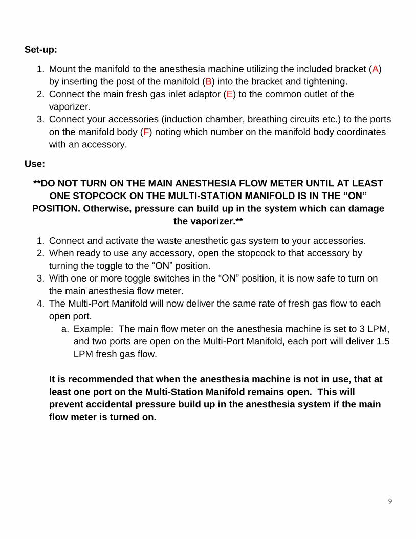
Set-up:
1. Mount the manifold to the anesthesia machine utilizing the included bracket (A)
by inserting the post of the manifold (B) into the bracket and tightening.
2. Connect the main fresh gas inlet adaptor (E) to the common outlet of the
vaporizer.
3. Connect your accessories (induction chamber, breathing circuits etc.) to the ports
on the manifold body (F) noting which number on the manifold body coordinates
with an accessory.
Use:
**DO NOT TURN ON THE MAIN ANESTHESIA FLOW METER UNTIL AT LEAST
ONE STOPCOCK ON THE MULTI-STATION MANIFOLD IS IN THE “ON”
POSITION. Otherwise, pressure can build up in the system which can damage
the vaporizer.**
1. Connect and activate the waste anesthetic gas system to your accessories.
2. When ready to use any accessory, open the stopcock to that accessory by
turning the toggle to the “ON” position.
3. With one or more toggle switches in the “ON” position, it is now safe to turn on
the main anesthesia flow meter.
4. The Multi-Port Manifold will now deliver the same rate of fresh gas flow to each
open port.
a. Example: The main flow meter on the anesthesia machine is set to 3 LPM,
and two ports are open on the Multi-Port Manifold, each port will deliver 1.5
LPM fresh gas flow.
It is recommended that when the anesthesia machine is not in use, that at
least one port on the Multi-Station Manifold remains open. This will
prevent accidental pressure build up in the anesthesia system if the main
flow meter is turned on.

10
The Scivena Scientific Sealed Induction Chamber allows for safe and effective
anesthetic induction of rodents while protecting the user from waste
anesthetic gas exposure.
A
B D
C
E
A. Chamber lid with airtight seal gasket
B. Chamber body with seal clamps
C. 15mm female gas inlet (O2/gas or CO2) D. 22mm male waste gas evacuation port
a. 19mm EVAC ports available
E. Five foot extension hose with 15mm female adaptors
Sealed Induction Chamber User Instructions
RES644 3 Liter
RES645 5 Liter
RES646 7 Liter

11
Set-Up:
1. Place chamber on level surface.
2. Connect one end of the extension hose to the common outlet of the anesthesia
machine, Scivena Scientific Multi-Port Manifold outlet port, or any diverter system
with a male common outlet on the end of the tubing, utilizing the 15mm male
adaptor on the extension hose (E).
3. Connect opposite end of the extension hose to the 15mm gas inlet on the
induction chamber (C).
4. Connect 22mm EVAC tubing to the 22mm male waste gas evacuation port on
the induction chamber (D).
a. Connect 22mm tubing to waste gas management system.
b. **The Sealed Induction Chamber must be used with either a passive waste
gas management system, or if using an active waste gas vacuum, a
Scivena Scientific Waste Gas Interface (RES505 and EVC630).
5. Remove the lid of the chamber by pulling the blue secure clamps outward and
down to release.
Use:
1. Make sure the waste anesthetic gas system is in place and functioning.
2. Before turning on any anesthetic gas, place the subject into the chamber and
secure the lid using the blue clamps- the chamber is now sealed.
3. Turn on the fresh gas flow using the main flow meter on the anesthesia machine.
a. Recommended fresh gas flow for induction chambers is 2 LPM.
4. Turn the vaporizer on to desired concentration.
a. Recommended vaporizer concentration for induction chambers is 2-3%.
5. Once subject is anesthetized, turn off the vaporizer leaving the main flow meter
on to 2LPM.
6. Using the O2 flush valve on the anesthetic machine, flush pure O2 through the
chamber to remove remaining anesthetic gas.
Recommended purge times:
RES644 - 3 Liter- 90 seconds
RES645 - 5 Liter- 105 seconds
RES646 - 7 Liter-115 seconds
7. Once chamber is sufficiently purged, turn off fresh gas flow to the chamber, open
chamber lid, remove subject and replace chamber lid.

12
Nosecone with Pre-Cut Diaphragm
Close-up View
The Rat and Mouse Non-Rebreathing Circuit is specially designed to both deliver
fresh anesthetic gas to rats and mice, and effectively remove waste anesthetic gases-
all in one, complete system. When used properly, the nosecone diaphragm
minimizes waste anesthetic gas leaks into the environment- even when using a
passive waste anesthetic gas removal system.
C
B
D
A
A. Fresh anesthetic gas delivery tube with 15mm female adaptor. Connects to
common outlet of the vaporizer on the anesthesia machine.
B. Fresh anesthetic delivery nosecone body.
C. Nosecone diaphragm with ring.
D. Waste anesthetic gas outlet for 19mm or 22mm EVAC tubing.
Rat and Mouse Non-Rebreathing Circuit
User Instructions
RES500

13
Set-Up:
1. Connect the fresh anesthetic gas delivery tube to the common outlet of the
vaporizer or Diverter System utilizing the 15mm female adaptor (A).
2. Secure the pre-cut latex diaphragm (C) onto the nosecone (B) utilizing the
included O-ring. Position the diaphragm so that the pre-cut hole is centered.
a. You can also position the hole off center to coincide with the size/desired
position of the rodent subject.
3. Connect either 19mm or 22mm EVAC tubing to the waste gas outlet of the
breathing circuit (D).
4. Connect the opposite end of the EVAC tubing to your waste gas management
system.
5. When the rodent subject is in place in the nosecone, the hole in the diaphragm
should seal just enough around the subject muzzle to keep waste anesthetic
gases from leaking, but not so tight that the diaphragm risks putting undue
pressure on the muzzle.
a. The precut hole in the diaphragm is sufficient to accommodate most small
rodent muzzles. However, you may need to make the hole larger for
rodents over 400gm.
Use:
1. Make sure waste anesthetic gas management system is in place and functioning.
2. Place anesthetized subject’s muzzle into the nosecone/diaphragm, making sure
the diaphragm seals around the subject’s muzzle.
3. Turn on the fresh anesthetic gas flow to the circuit.
a. Recommended fresh gas flow rate is 0.5-1.5 LPM at 1-2% Isoflurane
concentration.
4. When finished with procedure, turn vaporizer and fresh gas flow to zero, and
remove subject from the nosecone/diaphragm to recovery area.
14
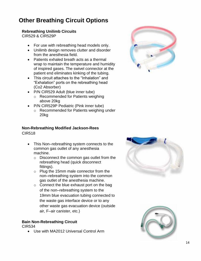
Rebreathing Unilimb Circuits CIR529 & CIR529P
For use with rebreathing head models only.
Unilimb design removes clutter and disorder from the anesthesia field.
Patients exhaled breath acts as a thermal wrap to maintain the temperature and humidity of inspired gases. The swivel connector at the patient end eliminates kinking of the tubing.
This circuit attaches to the “Inhalation” and “Exhalation” ports on the rebreathing head (Co2 Absorber)
P/N CIR529 Adult (blue inner tube) o Recommended for Patients weighing
above 20kg
P/N CIR529P Pediatric (Pink inner tube) o Recommended for Patients weighing under
20kg
Non-Rebreathing Modified Jackson-Rees
CIR518
This Non–rebreathing system connects to the common gas outlet of any anesthesia machine. o Disconnect the common gas outlet from the
rebreathing head (quick disconnect fittings).
o Plug the 15mm male connector from the non–rebreathing system into the common gas outlet of the anesthesia machine.
o Connect the blue exhaust port on the bag
of the non–rebreathing system to the
19mm blue evacuation tubing connected to
the waste gas interface device or to any
other waste gas evacuation device (outside
air, F–air canister, etc.)
Bain Non-Rebreathing Circuit CIR534
Use with MA2012 Universal Control Arm
Other Breathing Circuit Options

15
Provides body temperature regulation, fresh anesthetic gas delivery, waste
anesthetic gas removal and subject security – all in one convenient product.
A. 22mm Waste gas outlet
B. Non-Rebreathing Circuit fresh gas inlet
C. Non-rebreathing circuit holding block
D. Rat and Mouse Non-Rebreathing Circuit
E. Procedure platform
F. Tie-down attachment
G. Downdraft
Rodent Heated Surgical Station with
Downdraft Waste Gas Management
RES4000
A
D
E
G
F
C B

16
Set-Up and Use:
1. Place Surgical Station on level surface
2. Connect warm water circulating pump to included attachments and turn on- allow
platform to warm for approximately 5 minutes.
3. Insert breathing circuit waste gas outlet (D) into holding block (C) as shown in
picture above.
4. Attach active vacuum source to waste gas outlet (A) with 22mm EVAC tubing
and turn on.
5. Attach Rat and Mouse Non-Rebreathing Circuit fresh gas inlet (B) to fresh gas
outlet of anesthesia machine using included 15mm male adaptors.
6. The Surgical Station is now ready to use

17
The Multi-Station Surgical Board delivers fresh anesthetic gas to up to six
rodent subjects and provides a means to effectively remove waste anesthetic
gases, all while keeping the anesthetized subjects securely in place.
C B
A
F
E
FIGURE #1 D
A. Six Port Supply Manifold
B. Manifold waste gas exit port
C. Coaxial Rat and Mouse Non-Rebreathing Circuit (up to six)
D. Procedure platform
E. Movable tie-down anchors
F. Tie-down material
Multi-Station Surgical Board User Instructions
RES3200
18
Set-up and Use:
1. Place the Surgical Board on a level surface.
2. Place the nosecones (C) into the manifold (A) with the fresh gas inlet tubing on
the top surface (as shown in FIGURE #1).
3. Connect the nosecones to the anesthesia machine vaporizer common outlet
using Scivena Scientific’s Flow Balanced Multi-Station Manifold or any other
diverter system that accepts a 15mm male adaptor.
4. Connect 22mm EVAC tubing to the manifold waste gas exit port (B) and connect
to an activated charcoal canister or Scivena Scientific Waste Gas Interface if
using with an active vacuum source.
5. Place the tie-down anchors (E) in the desired positions.
6. Use the tie-down materials (F) to secure the anesthetized animals in place once
they are on the surgical board.
7. If not using all six stations, use included plugs to occlude unused stations.

19
For Use with Fan Style Waste Gas Evacuation Unit (EVC3000). The interface unit
balances the pressure between the anesthesia machine and the active, fan style
evacuation unit.
A. 19mm Inlet - connects to waste gas outlet of anesthesia machine or
accessory.
B. Secondary inlet with included cap- connects to waste gas outlet of
induction chamber.
C. Interface Manifold
D. Reservoir Bag
E. Room Air Intake
F. 22mm Outlet- connects to fan style waste gas evacuation system.
Waste Gas Interface User Instructions
EVC630
A B
C
E
F
D
E
FRONT SIDE

20
Set-up:
1. Mount the interface to the anesthesia machine with included bracket and
mounting hardware.
2. Connect blue 19mm EVAC tubing from the 19mm Inlet to the waste gas outlet
on the pop-off valve of the anesthesia machine rebreathing head (for
rebreathing machines) or the waste gas outlet of the non-rebreathing circuit
(for machines without rebreathing head).
3. Connect the 19mm blue EVAC tubing from the secondary inlet to the waste
gas outlet of the induction chamber.
4. Connect the clear 22mm EVAC tubing to the Fan Style Waste Gas Evacuation
System.
Use:
1. Turn the waste gas evacuation unit on.
2. Use the induction chamber to anesthetize the subject.
3. When finished with the induction chamber, remove the tubing from the
Secondary Inlet on the Waste Gas Interface and cap off with included cap.
4. Place subject on nosecone and maintain anesthesia as normal.
5. When finished with procedure, turn evacuation unit off.

21
For Use with Pump Style Waste Gas Evacuation Unit (EVC3100). The
interface unit balances the pressure between the anesthesia machine and
the active, pump style evacuation unit.
A. 22mm Inlet - connects to waste gas outlet of breathing circuit or
induction chamber.
B. Interface Body with room air intake.
C. ¼ Inch ID Hose barb Outlet- connects to pump style waste gas
evacuation system or WAGD wall outlet.
D. Vacuum stopcock- shown in “OFF” position.
A B C
D
Waste Gas Interface User Instructions
RES505

22
Set-up:
1. Connect clear 22mm EVAC tubing from the 22mm Inlet to the waste gas
outlet on the breathing circuit or induction chamber.
2. Connect ¼” ID EVAC tubing/hose from pump waste gas evacuation unit
to the Hose barb Outlet.
Use:
1. Turn the waste gas evacuation unit on.
2. Turn the Vacuum Stopcock (D) to the “ON” position.
3. Use the accessory and as normal when Waste Gas Interface is
connected inline.
4. When finished with the accessory, turn the anesthetic gas off to that
accessory and turn the Vacuum Stopcock in the line to the “OFF”
position.
5. When finished with procedures, turn waste gas evacuation unit off.

23
Warranty / Return Policy
Scivena Scientific Anesthesia Innovations warrants that each product or part shall be free from defects in workmanship and materials, under normal use and with appro-priate maintenance, for 10 (ten) years from the date of purchase. For plastic, rubber and disposable parts or items, Supera Anesthesia Innovation warrants only that each such part and item shall be free from defects in workmanship and materials at the time of delivery.
This warranty shall be void for any product that has been altered, defaced or removed from the original Scivena Scientific Anesthesia Innovation product.
Scivena Scientific Anesthesia Innovations shall not be liable for any damage, injury or loss arising out of the use of the product, whether as a result of a defect in the product or otherwise, if, prior to such damage, injury or loss, the product was (1) damaged, misused, or misapplied; (2) repaired, altered or modified by persons other than Scivena Scientific Anesthesia Innovations; (3) not installed in strict compliance with the applicable codes and ordinances; (4) not installed by Scivena Scientific Anesthesia Innovations or an authorized Supera Anesthesia Innovation dealer.
UNDER NO CIRCUMSTANCES SHALL Scivena Scientific Anesthesia Innovations BE LIABLE FOR INCIDENTAL OR CONSEQUENTIAL DAMAGES AS THOSE TERMS ARE DEFINED IN THE UNIFORM COMMERCIAL CODE.
All items returned for service or repairs are the responsibility of the customer. Proper
packing methods should be used in returning items to Scivena Scientific Anesthesia
Innovations.

24
SHIPPING POLICIES
1. Do not sign the Bill Of Lading until you have inspected the box or crate. 2. Examine the box AS it is delivered and BEFORE the truck/driver leaves. 3. If there is any evidence of damage when it arrives, note it in detail with the
phrase “possible concealed damage” on the bill of lading and immediately call the office for instructions before the truck/driver leaves if at all possible.
4. If there is obvious damage such as a hole in the box, a crushed box, etc., refuse the shipment. The product will then go back to the freight company’s terminal where they are entirely responsible.
5. Open and inspect your product as soon as possible. DO NOT WAIT. 6. If you find damage, take as many photographs of everything as soon as you can
and email them to [email protected] 7. Note: unless the following procedures are followed correctly and we are notified
within ten (10) days, SCIVENA SCIENTIFIC LLC cannot accept any responsibility for the problems that may ensue.
DO NOT RETURN ANY DAMAGED GOODS TO SUPERA LLC WITHOUT PRIOR
AUTHORIZATION OF SCIVENA SCIENTIFIC, LLC AND THE CARRIER.
KEEP ALL PACKAGING!
DO NOT RETURN ANY DAMAGED ITEMS UNTIL SHIPPING INSTRUCTIONS ARE RECEIVED.
ALL CLAIMS MUST BE FILED WITHIN TEN (10) DAYS OF RECEIPT OF GOODS. IF YOU HAVE ANY QUESTIONS CONTACT SCIVENA SCIENTIFIC DIRECTLY AT
877-615-5632.
25
DOCUMENTATION
Date purchased:
Purchased from:
Machine serial number:
Vaporizer serial number:
Machine service information:
Service Date: Service information:
Service Date: Service information:
Service Date: Service information: