Operator Manual - NORAC Systems International...Changing to Automatic or Manual Mode: From the run...
54
Operator Manual Version 2 Software
Transcript of Operator Manual - NORAC Systems International...Changing to Automatic or Manual Mode: From the run...
Operator Manual Version 2 Software

Printed in Canada Copyright 2012 by NORAC Systems International Inc. Reorder P/N: UC4.5-BC-MANUAL-OPERATOR Rev D (UC4.5 Operator Manual)
NOTICE: NORAC Systems International Inc. reserves the right to improve products and their specifications without notice and without the requirement to update products sold previously. Every effort has been made to ensure the accuracy of the information contained in this manual. The technical information in this manual was reviewed at the time of approval for publication.

Contents
1 INTRODUCTION ................................................................................................... 1 1.1 Warranty Registration .................................................................................................................................................... 1
2 SAFETY PRECAUTIONS ...................................................................................... 2 3 KEY FEATURES ...................................................................................................... 3 4 SYSTEM DESCRIPTION ....................................................................................... 4 4.1 General UC4.5 System Layout ...................................................................................................................................... 4
4.2 Height Sensors .................................................................................................................................................................. 5
4.3 Roll Sensors ....................................................................................................................................................................... 5
4.4 Position Sensors ............................................................................................................................................................... 6
4.5 Control Panel .................................................................................................................................................................... 6
5 ICON DESCRIPTIONS .......................................................................................... 7 6 OPERATION ........................................................................................................... 8 6.1 Basic UC4.5 Operation ................................................................................................................................................... 8
6.2 Sprayer Switches .............................................................................................................................................................. 9
6.3 Main Menu Settings ........................................................................................................................................................ 10
6.4 Main Menu Map .............................................................................................................................................................. 11
7 UNDERSTANDING THE UC4.5 SYSTEM ........................................................ 12 7.1 Ditches, Waterways and Outside Rounds ................................................................................................................ 12
7.2 Driving Through Ditches and Over Terraces .......................................................................................................... 12
7.3 Soil Mode, Crop Mode and Hybrid Mode ................................................................................................................ 12
7.4 Sensing Further Ahead of the Boom .......................................................................................................................... 13
7.5 Height Sensor Limitations ............................................................................................................................................ 13
8 SETUP .................................................................................................................... 14 8.1 Automatic System Setup ............................................................................................................................................... 14
8.2 Retune .............................................................................................................................................................................. 19
8.3 Manual Setup ................................................................................................................................................................... 20
8.4 Quick Install..................................................................................................................................................................... 29
9 OPTIONAL KITS .................................................................................................. 31 9.1 Main Lift Kit ..................................................................................................................................................................... 31
9.2 Severe Terrain Kit ......................................................................................................................................................... 31
9.3 Enhanced Stability Kit .................................................................................................................................................... 31
9.4 Roll Bias (Active Roll) Kit ............................................................................................................................................. 32
10 OPTIONS ............................................................................................................... 33 10.1 Headland Assist .............................................................................................................................................................. 33
10.2 Remote Switches ............................................................................................................................................................ 35
10.3 High Oil Temperature Alarm ...................................................................................................................................... 35
10.4 Sensor Reading Alarm ................................................................................................................................................... 35
10.5 Minimum Height Mode ................................................................................................................................................. 35
10.6 Changing the Units ......................................................................................................................................................... 36
10.7 Valve and Air Temperature ......................................................................................................................................... 36

11 MAINTENANCE ................................................................................................... 37 12 TROUBLESHOOTING ........................................................................................ 38 12.1 General Operation ........................................................................................................................................................ 38
12.2 Sensors ............................................................................................................................................................................. 39
12.3 Hydraulics ........................................................................................................................................................................ 41
12.4 Boom Stability ................................................................................................................................................................. 43
12.5 Setup Messages ............................................................................................................................................................... 44
12.6 Operational Messages ................................................................................................................................................... 46
13 STATEMENT OF LIMITED WARRANTY ........................................................ 47 14 SPRAYER TYPES .................................................................................................. 48 15 UC4.5 MENU STRUCTURE ................................................................................ 49

1
1 Introduction
Congratulations on your purchase of a NORAC UC4.5 Spray Height Control System. This system has an unmatched reputation within the industry for boom protection and spray height accuracy.
When properly used, the UC4.5 Spray Height Control system provides protection from boom damage as well as improving sprayer efficiency and chemical performance by ensuring correct chemical application.
To fully understand your new system and use it to its fullest capacity it is recommended that you read this manual. This manual provides a general overview, key features, operating instructions, assistance with system setup, regular maintenance recommendations and troubleshooting.
If you have any questions, feedback or comments regarding the NORAC UC4.5 Spray Height Control system, please contact us.
The information in this manual applies to systems with Version 2 software.
2
2 Safety Precautions
The UC4.5 Spray Height Control system will greatly improve spray height accuracy and protect the boom against damage in a wide variety of field conditions. However, under some circumstances performance may be limited. The operator of the sprayer must remain alert at all times and override the automatic control when necessary.
CAUTION
Under no circumstances should any service work be performed on the machinery while the UC4.5 Spray Height Control system is in the automatic mode.
Always ensure that the UC4.5 Spray Height Control system is powered down or in manual mode:
Before leaving the operator’s seat.
While the machine is not moving.
When transporting the machine.
Before working on any part of the booms:
Set the UC4.5 system to manual mode.
Turn the sprayer engine off.
Do not operate this system before:
Reading and understanding the operator’s manual.
Thoroughly understanding the machine operation.
3
3 Key Features
Non-contact Sensing:
Sensing is done using ultrasonic sensors which means no parts of the UC4.5 Spray Height Control System come in contact with the ground.
Using a non-contact system means there will be no additional forces put on the boom, which could cause damage to the sprayer boom.
Automatic Software Setup:
The system completes an automatic system setup, which calibrates the software specifically for the sprayer.
This provides the maximum performance for the height control system.
Individual Boom Overrides:
When necessary one boom section can be put into manual mode to avoid an obstacle, while the other boom sections stay in automatic.
This can take the stress out of spraying along obstacles such as fences because the operator only has to watch the boom along the obstacle, knowing that the UC4.5 is maintaining the height on the rest of the boom sections.
NOTE: Individual boom overrides may not be available for all sprayer makes and models. Consult your sales representative or technical support with any questions or concerns.
Smart Sensor Technology:
All sensors are designed by NORAC specifically for the agricultural industry.
4
4 System Description
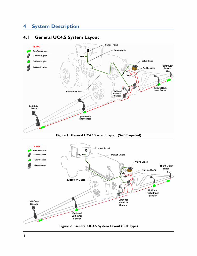
4.1 General UC4.5 System Layout
Figure 1: General UC4.5 System Layout (Self Propelled)
Figure 2: General UC4.5 System Layout (Pull Type)
5
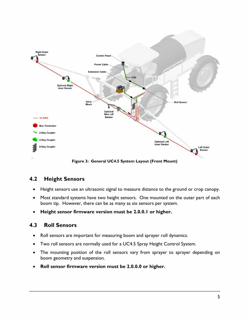
Figure 3: General UC4.5 System Layout (Front Mount)
4.2 Height Sensors
Height sensors use an ultrasonic signal to measure distance to the ground or crop canopy.
Most standard systems have two height sensors. One mounted on the outer part of each boom tip. However, there can be as many as six sensors per system.
Height sensor firmware version must be 2.0.0.1 or higher.
4.3 Roll Sensors
Roll sensors are important for measuring boom and sprayer roll dynamics.
Two roll sensors are normally used for a UC4.5 Spray Height Control System.
The mounting position of the roll sensors vary from sprayer to sprayer depending on boom geometry and suspension.
Roll sensor firmware version must be 2.0.0.0 or higher.

6
4.4 Position Sensors
Position sensors are used to measure boom suspension position and/or cylinder position.
The function of position sensors may be similar to that of a pair of roll sensors.
The mounting position of the position sensors vary from sprayer to sprayer depending onboom geometry and suspension.
4.5 Control Panel
The UC4.5 control panel (Figure 4) is the main component of the UC4.5 Spray Height Control System. The control panel uses the readings from the ultrasonic sensors to control solenoid operated valves that in turn adjust the boom height. The control panel will:
Indicate when the system is in AUTOMATIC or MANUAL mode.
Indicate any hydraulic action which is underway.
Accept input to adjust all control system settings.
Figure 4: UC4.5 Control Panel
LCD Screen
- Button
Auto (Yes) Button
Power Switch
Sensor Display Button
+ Button
Setup Button Manual Button
Boom Roll Switch (Optional)
7
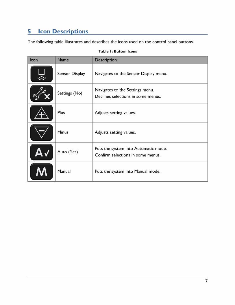
5 Icon Descriptions
The following table illustrates and describes the icons used on the control panel buttons.
Table 1: Button Icons
Icon Name Description
Sensor Display Navigates to the Sensor Display menu.
Settings (No) Navigates to the Settings menu. Declines selections in some menus.
Plus Adjusts setting values.
Minus Adjusts setting values.
Auto (Yes) Puts the system into Automatic mode. Confirm selections in some menus.
Manual Puts the system into Manual mode.

8
6 Operation
6.1 Basic UC4.5 Operation
Upon power-up a sequence of messages are temporarily displayed on the control panel LCD screen. The system is ready for use once the run screen is displayed.
To access either the "SENSOR DISPLAY" ( ) or "SETUP" ( ) menus, the control panel must be at the run screen.
Press the button corresponding with the menu desired.
Adjust the menu settings using the buttons when the prompt is displayed.
After 30 seconds menu prompts will return to the run screen.
To return to the run screen press and hold for two seconds.
New settings take effect once the run screen is displayed.
When the UC4.5 Height Control System is in automatic mode, arrows will appear on the screen indicating the UC4.5 system is making a correction. Often the correction will be very small and there may not be a noticeable change in boom position.
Figure 5: Run Screen
Changing to Automatic or Manual Mode:
From the run screen, press the control panel "AUTO" button ( ) to put the system into automatic mode. The run screen will show an "A" for each side of the boom to indicate the system is in auto. Pressing the "MANUAL" button ( ) or a sprayer joystick function will put the system into manual mode. The run screen will show an "M" for each boom to indicate the system is in manual mode.
A 45 A
LEFT BOOM ARROW
AUTO / MANUAL (Left Boom) or
MAIN LIFT ARROW
TARGET HEIGHT
RIGHT BOOM ARROW
AUTO / MANUAL (Right Boom)
9
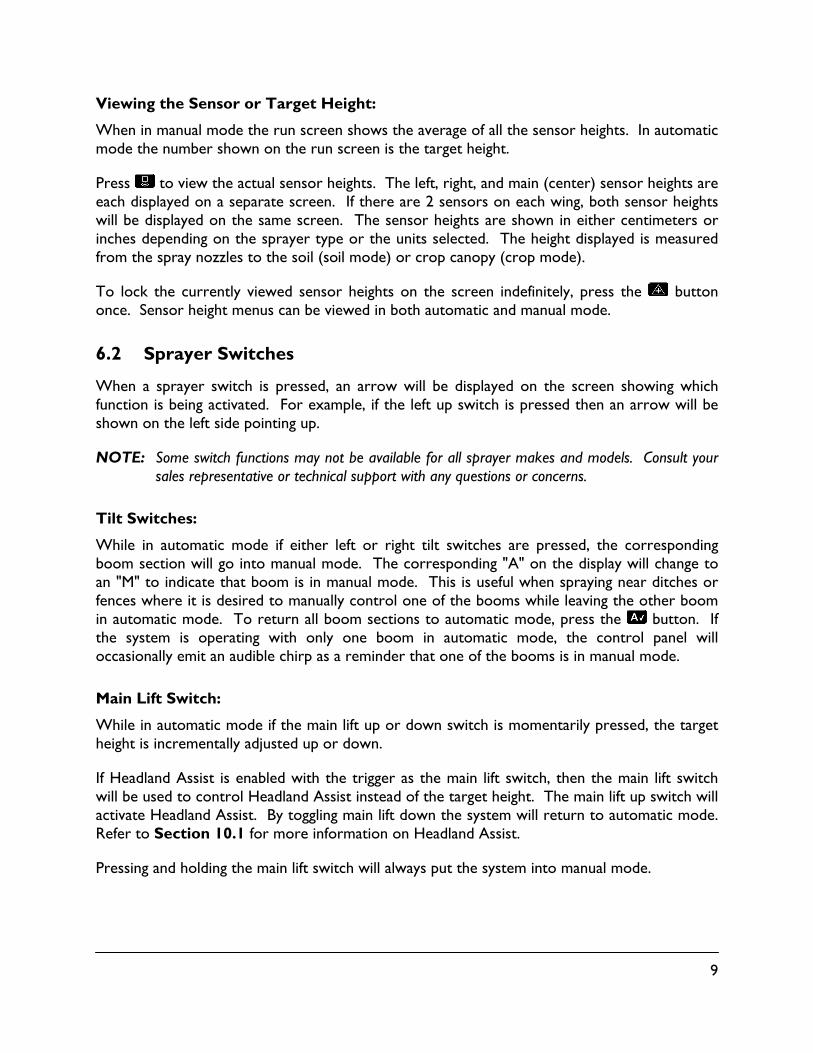
Viewing the Sensor or Target Height:
When in manual mode the run screen shows the average of all the sensor heights. In automatic mode the number shown on the run screen is the target height.
Press to view the actual sensor heights. The left, right, and main (center) sensor heights are each displayed on a separate screen. If there are 2 sensors on each wing, both sensor heights will be displayed on the same screen. The sensor heights are shown in either centimeters or inches depending on the sprayer type or the units selected. The height displayed is measured from the spray nozzles to the soil (soil mode) or crop canopy (crop mode).
To lock the currently viewed sensor heights on the screen indefinitely, press the button once. Sensor height menus can be viewed in both automatic and manual mode.
6.2 Sprayer Switches
When a sprayer switch is pressed, an arrow will be displayed on the screen showing which function is being activated. For example, if the left up switch is pressed then an arrow will be shown on the left side pointing up.
NOTE: Some switch functions may not be available for all sprayer makes and models. Consult your sales representative or technical support with any questions or concerns.
Tilt Switches:
While in automatic mode if either left or right tilt switches are pressed, the corresponding boom section will go into manual mode. The corresponding "A" on the display will change to an "M" to indicate that boom is in manual mode. This is useful when spraying near ditches or fences where it is desired to manually control one of the booms while leaving the other boom in automatic mode. To return all boom sections to automatic mode, press the button. If the system is operating with only one boom in automatic mode, the control panel will occasionally emit an audible chirp as a reminder that one of the booms is in manual mode.
Main Lift Switch:
While in automatic mode if the main lift up or down switch is momentarily pressed, the target height is incrementally adjusted up or down.
If Headland Assist is enabled with the trigger as the main lift switch, then the main lift switch will be used to control Headland Assist instead of the target height. The main lift up switch will activate Headland Assist. By toggling main lift down the system will return to automatic mode. Refer to Section 10.1 for more information on Headland Assist.
Pressing and holding the main lift switch will always put the system into manual mode.

10
6.3 Main Menu Settings
Sensor Mode:
Soil mode configures the sensors to read the height from the spray nozzles to the ground. Crop mode will read the height from the spray nozzles to the top of the crop canopy. Hybrid mode will use both the distance measured to the crop canopy and the distance measured to the ground to determine the crop height. Hybrid mode will create a virtual crop canopy using historic crop height information preventing the boom from tracking down into the crop when the crop canopy is thin or in areas of downed crop or wheel tracks.
To change sensor modes, press twice from the run screen. The screen will display either "SOIL", "CROP", or “HYBRID”. Use the buttons to change the setting. For more information on sensor modes refer to Section 7.3.
Sensitivity:
The sensitivity can be adjusted from 1 to 10, with 5 being the default setting. A lower number will reduce the system sensitivity. Higher settings will speed up the response and also create a greater demand on the hydraulics.
To change the sensitivity, press the button once from the run screen. The current sensitivity will be displayed. Use the buttons to change the setting.
Target Height:
The target height is the height that the operator would like the boom to be set at when spraying. When operating in soil mode, the target height is measured from the spray nozzles to the soil. In crop mode the target height is measured from the crop canopy to the spray nozzles. In Hybrid mode the target height is measured from the crop canopy, or in the absence of a crop canopy, to the virtual crop canopy. The target height can be changed from the run screen while the system is in automatic mode by using the buttons.
Severe Terrain Mode:
Some sprayers have the ability to fold in the boom tips and spray with only the inner sections of the boom. If the sprayer has this ability and is equipped with a five sensor system (severe terrain kit) then this feature may be used when spraying with the tips folded in.
Press from the run screen until "Tips on" is displayed. Use the buttons to turn it on or off. By turning the tips off, the two outer sensors on the wings will be disabled and only the inner wing sensors will be used to control the height.
When the tips are turned off the run screen will show a lower case "a" in automatic to indicate the outer sensors are turned off. The Severe Terrain Mode is defaulted to “Tips on” and will return to "Tips on" anytime the power is cycled. When spraying with the full boom, the setting should be "Tips on" to allow the outer sensors to operate again.

11
6.4 Main Menu Map
Sensor Settings
Severe Terrain Mode
Roll Information
Center Height
Right Height
Left Height
Run Screen
Sensitivity
Crop or Soil Mode
Retune Hydraulics
Control Settings
Figure 6: UC4.5 Main Menu Map
Note: Refer to Section 15 for a full menu structure map.
Tips on
More ?
11 ()
89
87 89
90 89
M 82 M
Sensi 5
Soil On
ReTune ?
More ?
Sensor Display
Setup

12
7 Understanding the UC4.5 System
The UC4.5 Spray Height Control System will work well in most situations. As with any equipment, it is important that the operator remain alert at all times. There may be some situations and terrain where performance is limited and in these situations the operator must resume manual control of the booms.
Sprayer hydraulics and boom suspension systems are the governing components to boom reaction time. The maximum hydraulic speed of the boom is determined by the sprayer manufacturer and is not diminished by the addition of the UC4.5 hydraulic system.
7.1 Ditches, Waterways and Outside Rounds
In many situations, it is necessary to spray with one sensor reading over terrain that does not reflect the same situation of the rest of the boom. These situations may arise when spraying over ditches, waterways, or field edges. When spraying in these situations, the operator must remain alert and override the height control system when necessary.
7.2 Driving Through Ditches and Over Terraces
Changes in terrain such as driving over terraces or through ditches are special performance situations. This type of terrain can cause the sprayer to pitch and roll significantly and when operating at high speeds this can cause rapid changes in boom tip height. Sprayer hydraulic systems are not capable of tip speeds high enough to correct for the boom tip error. There are two solutions to this problem.
The first is for the operator to recognize these situations before they occur and manually raise the boom to a safe height.
The second is to add the Roll Control option, if one is available for the specific sprayer. This will compensate for the sprayer roll and make the required corrections faster and smoother, allowing for increased boom protection and higher spraying speeds. For a description of the Roll Control, see Section 9.4.
7.3 Soil Mode, Crop Mode and Hybrid Mode
Height sensors use “smart sensor” technology, which take measurements from both the top of crop canopy and from the soil surface. This allows the user to select Hybrid, Crop or Soil Mode. In Soil Mode the target height is measured from the soil to the sprayer nozzle. In Crop Mode the target height is measured from the crop canopy to the sprayer nozzle. Hybrid mode uses a combination of the crop and oil readings to improve control.
Hybrid and Crop Mode are usually used when operating in mature cereal grains, row crops or specialty crops. Soil Mode is generally used to follow the ground through young crops, stubble or normal trash.
In row-crops, Hybrid Mode will work best with the sensor placed directly above a row.

13
Some crops will produce a more varying canopy than others. In these situations, the severe terrain option (Section 9.1) will provide more representative measurements and better performance. Hybrid mode is recommended for uneven crops.
When mounting the main lift height sensor, ensure the sensor does not measure behind a wheel or tramline, when driving straight or turning. The crop behind a wheel will be flattened, resulting in inaccurate readings and poor Crop Mode performance.
7.4 Sensing Further Ahead of the Boom
A common misconception is moving the sensor further ahead of the boom will increase performance. Moving the sensor further ahead of the boom increases the distance between the nozzle and sensor. This puts the sensor at a different location within the field than the nozzles, which introduces a height error at the nozzles. In severe terrain this height error can bring the nozzles close to the ground as the sensor reads over the crest of the hill or down a ditch.
7.5 Height Sensor Limitations
The UC5™ sensors are designed and built specifically for agricultural purposes. However, the ultrasonic transducer must be clean and dry for optimal performance. The foam disc fitted into the bottom of the sensor protects the transducer from dust. If the protective foams become wet from rain or drift from the spray nozzles the sensors may have trouble reading. Furthermore, if the transducer itself becomes wet, leave the UC5™ system on, but in Manual Mode. The transducer’s vibrations will clean itself of the water and after a few minutes it will begin to function again.
The height sensors will provide height readings from 22 to 300cm (9 to 120 inches), under typical conditions.
In order to optimize sensor performance, the UC5™ sensor has a minimum distance that it will read, also known as the blanking range. As a result, the UC5™ sensor is designed to ignore targets closer than 8 inches (20cm) from the bottom of the sensor housing.
14
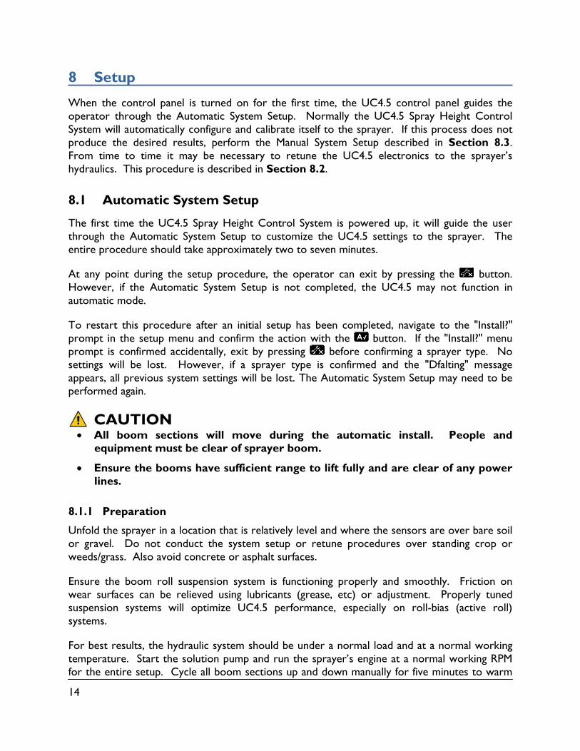
8 Setup
When the control panel is turned on for the first time, the UC4.5 control panel guides the operator through the Automatic System Setup. Normally the UC4.5 Spray Height Control System will automatically configure and calibrate itself to the sprayer. If this process does not produce the desired results, perform the Manual System Setup described in Section 8.3. From time to time it may be necessary to retune the UC4.5 electronics to the sprayer’s hydraulics. This procedure is described in Section 8.2.
8.1 Automatic System Setup
The first time the UC4.5 Spray Height Control System is powered up, it will guide the user through the Automatic System Setup to customize the UC4.5 settings to the sprayer. The entire procedure should take approximately two to seven minutes.
At any point during the setup procedure, the operator can exit by pressing the button. However, if the Automatic System Setup is not completed, the UC4.5 may not function in automatic mode.
To restart this procedure after an initial setup has been completed, navigate to the "Install?" prompt in the setup menu and confirm the action with the button. If the "Install?" menu prompt is confirmed accidentally, exit by pressing before confirming a sprayer type. No settings will be lost. However, if a sprayer type is confirmed and the "Dfalting" message appears, all previous system settings will be lost. The Automatic System Setup may need to be performed again.
CAUTION
All boom sections will move during the automatic install. People and equipment must be clear of sprayer boom.
Ensure the booms have sufficient range to lift fully and are clear of any power lines.
8.1.1 Preparation
Unfold the sprayer in a location that is relatively level and where the sensors are over bare soil or gravel. Do not conduct the system setup or retune procedures over standing crop or weeds/grass. Also avoid concrete or asphalt surfaces.
Ensure the boom roll suspension system is functioning properly and smoothly. Friction on wear surfaces can be relieved using lubricants (grease, etc) or adjustment. Properly tuned suspension systems will optimize UC4.5 performance, especially on roll-bias (active roll) systems.
For best results, the hydraulic system should be under a normal load and at a normal working temperature. Start the solution pump and run the sprayer’s engine at a normal working RPM for the entire setup. Cycle all boom sections up and down manually for five minutes to warm
15
the oil. For pull-type sprayers, ensure any hydraulic flow controls are adjusted for normal field operation. Changing the hydraulic flow controls after or during the system setup will affect the UC4.5 performance.
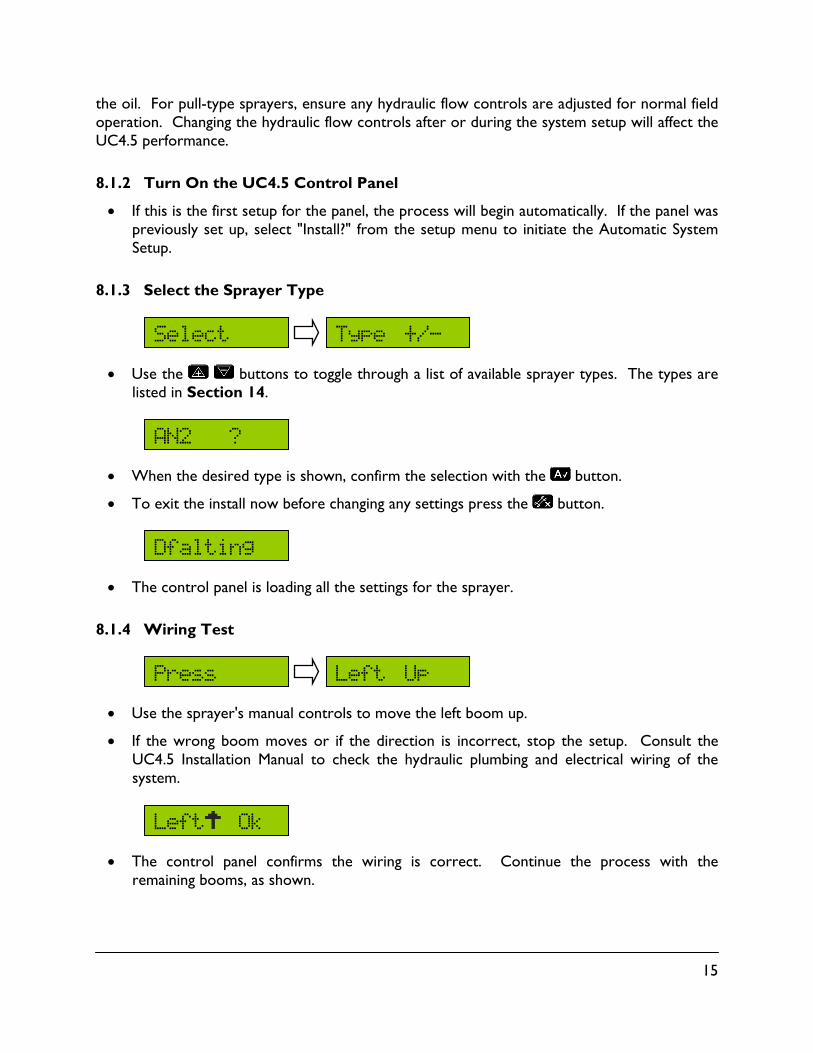
8.1.2 Turn On the UC4.5 Control Panel
If this is the first setup for the panel, the process will begin automatically. If the panel was previously set up, select "Install?" from the setup menu to initiate the Automatic System Setup.
8.1.3 Select the Sprayer Type
Use the buttons to toggle through a list of available sprayer types. The types are listed in Section 14.
When the desired type is shown, confirm the selection with the button.
To exit the install now before changing any settings press the button.
The control panel is loading all the settings for the sprayer.
8.1.4 Wiring Test
Use the sprayer's manual controls to move the left boom up.
If the wrong boom moves or if the direction is incorrect, stop the setup. Consult the UC4.5 Installation Manual to check the hydraulic plumbing and electrical wiring of the system.
The control panel confirms the wiring is correct. Continue the process with the remaining booms, as shown.
AN2 ?
Type +/-
Left Up
Select
Dfalting
Press
Left Ok

16
Note: Some sprayer types do not support a wiring test or they may support a different style of test. If there are no messages displayed in this step, simply continue as prompted by the panel.
8.1.5 Sensor Detect
Position all boom sections such that the nozzles are 35 inches (90 cm) from the ground.
Press to continue.
Note: If it is not possible to get all the booms set to exactly 35 inches (90 cm), the sensor height can be adjusted after the install is finished. Refer to Section 8.3.1 for more details.
Hold the button to begin the sensor detect sequence. The button must be held for the duration of the procedure. If is released, simply press and hold again to continue the procedure.
The control panel will automatically move the booms to detect and assign the sensors tothe correct locations.
Release the button to continue.
Switch Release
Proceed?
Hold Auto Until
“Done”
Height
35 inch Booms at Level
Left Dn Press
Rght Up Press
Rght Dn Press
Main Up Press
Main Dn Press

17
8.1.6 Boom Geometry Tuning
Exit the cab and manually push either boom tip down 1 – 3 feet (30 – 90 cm) for a moment and then let go.
Do not walk near the sensors when approaching the boom. Stay at least 3 feet from the sensor so as not to induce a measurement error.
Note: This step may not be applicable for all sprayer types.
8.1.7 Hydraulic Tuning
Hold the button to continue the hydraulic tuning. If is released before "Done" is displayed, simply press and hold again to continue the procedure.
The panel will display various messages as it is working. The messages are displayed for informational purposes only.
Release the button, the hydraulic tuning is complete.
Done
“Done”
Until Auto Hold
& let go ground near to
boom tip push Exit Cab
18
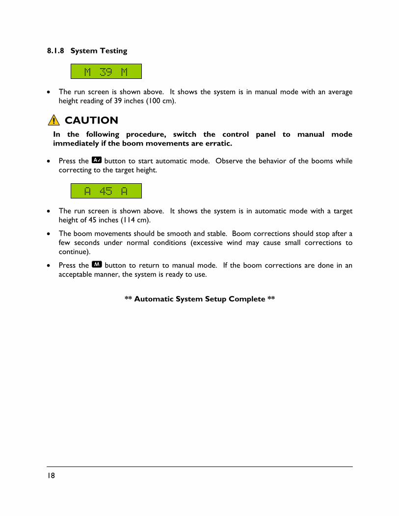
8.1.8 System Testing
The run screen is shown above. It shows the system is in manual mode with an averageheight reading of 39 inches (100 cm).
CAUTIONIn the following procedure, switch the control panel to manual mode immediately if the boom movements are erratic.
Press the button to start automatic mode. Observe the behavior of the booms while correcting to the target height.
The run screen is shown above. It shows the system is in automatic mode with a targetheight of 45 inches (114 cm).
The boom movements should be smooth and stable. Boom corrections should stop after afew seconds under normal conditions (excessive wind may cause small corrections tocontinue).
Press the button to return to manual mode. If the boom corrections are done in anacceptable manner, the system is ready to use.
** Automatic System Setup Complete **
A 45 A
M 39 M
19
8.2 Retune
From time to time it may be necessary to recalibrate (Retune) the UC4.5 electronics to the sprayer’s hydraulics. Examples of such times are:
A hydraulic solenoid valve has been changed.
The hydraulic pump has been changed or adjusted.
A different tractor has been connected to the sprayer.
The tractor’s hydraulic flow control has been adjusted.
If running a pull type sprayer and using different tractors to operate the sprayer, run the Retune procedure each time the tractor is changed. If there is a flow control for the boom hydraulics, set it prior to tuning. If the flow setting is changed by more than 20 percent, run a Retune.
Follow Section 8.1.1 (level booms, working RPM, etc.) before beginning the Retune. Navigate to the "Retune?" menu prompt in the SETUP ( ) menu and confirm with the button. The procedure described in the Automatic System Setup, starting at Section 8.1.7 will begin.
Note: The booms are to be leveled at a normal working height when Retune starts – it is not necessary to set them to 35 inches. The 35 inch height is only required during the Automatic System Setup.
20
8.3 Manual Setup
The UC4.5 Spray Height Control System will not operate in automatic mode until the system has been configured. It is recommended that the Automatic System Setup be used, but if necessary, a manual system setup may be used. The manual system setup involves setting up each sensor (programming serial numbers and sensor locations) as well as tuning the hydraulic parameters manually.
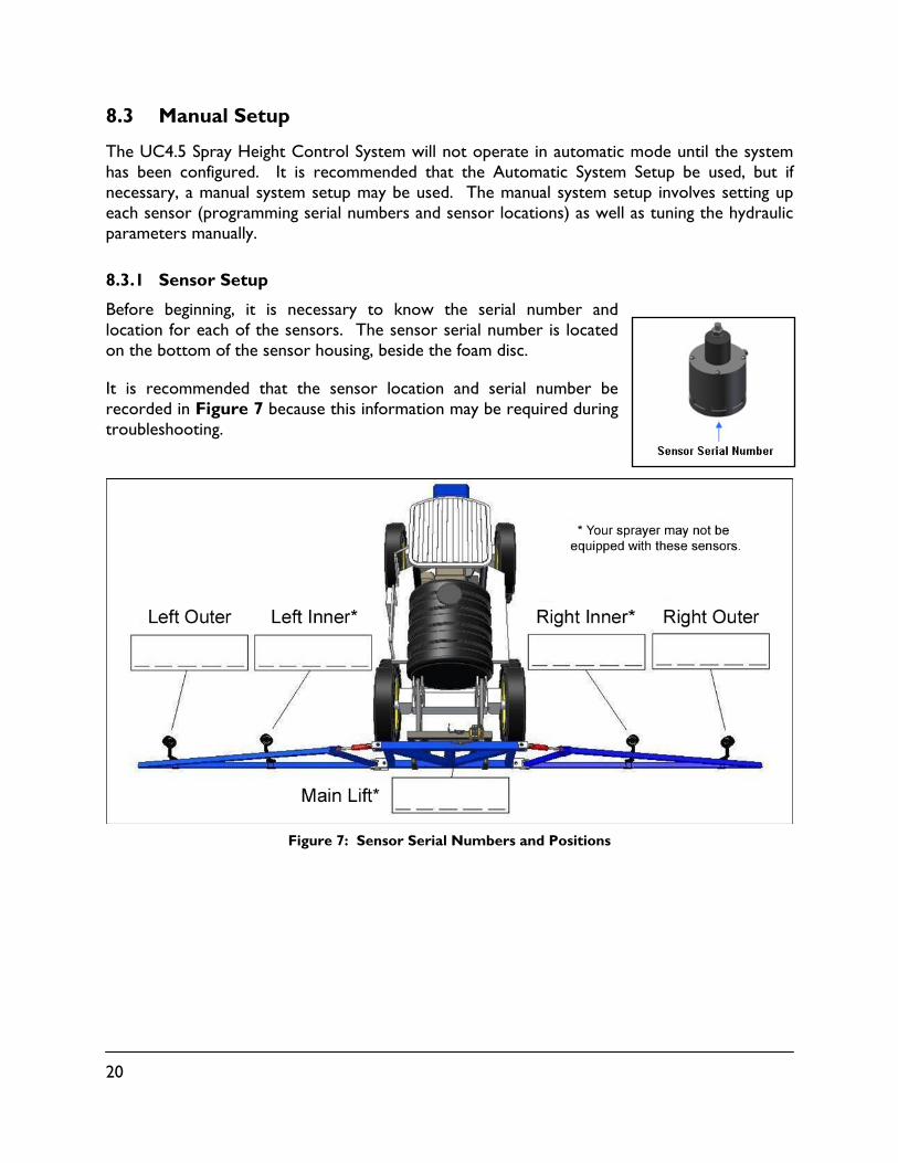
8.3.1 Sensor Setup
Before beginning, it is necessary to know the serial number and location for each of the sensors. The sensor serial number is located on the bottom of the sensor housing, beside the foam disc.
It is recommended that the sensor location and serial number be recorded in Figure 7 because this information may be required during troubleshooting.
Figure 7: Sensor Serial Numbers and Positions
21
Navigating to the Sensor Menu:
Ensure the UC4.5 control panel is in manual mode, at the run screen.
Navigate to the "More?" menu prompt in the SENSOR DISPLAY ( ) menu. Press to confirm.
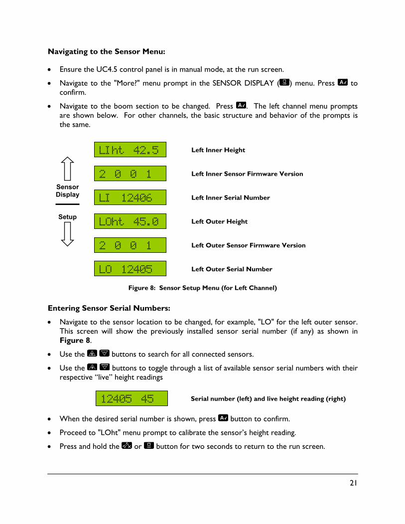
Navigate to the boom section to be changed. Press . The left channel menu prompts are shown below. For other channels, the basic structure and behavior of the prompts is the same.
Left Inner Height
Left Inner Sensor Firmware Version
Left Inner Serial Number
Left Outer Height
Left Outer Sensor Firmware Version
Left Outer Serial Number
Figure 8: Sensor Setup Menu (for Left Channel)
Entering Sensor Serial Numbers:
Navigate to the sensor location to be changed, for example, "LO" for the left outer sensor. This screen will show the previously installed sensor serial number (if any) as shown in Figure 8.
Use the buttons to search for all connected sensors.
Use the buttons to toggle through a list of available sensor serial numbers with their respective “live” height readings
Serial number (left) and live height reading (right)
When the desired serial number is shown, press button to confirm.
Proceed to "LOht" menu prompt to calibrate the sensor’s height reading.
Press and hold the or button for two seconds to return to the run screen.
LOht 45.0
2 0 0 1
LO 12405
LI 12406
2 0 0 1
LIht 42.5
12405 45
Sensor Display
Setup

22
Calibrating the Sensor’s Height Reading (Zero Height):
Ensure the sprayer boom is unfolded and the sensors are located over bare soil or gravel. Position the boom at a normal working height. Do not conduct this procedure over standing crop or tall grass/weedy areas. It is recommended to perform this calibration in soil mode.
Using a tape measure, measure the distance from the bottom of the spray nozzle to the ground (Figure 9). Use the spray nozzle closest to the sensor. Round this measurement to the nearest half-inch.
Figure 9: Measurement for Calibrating the Sensor Height
Navigate to the location measured, for example, "LOht" for the left outer sensor (Figure 8).
If the currently displayed height reading is not correct, adjust it using the buttons. The button will increase the reading; the button will decrease the reading.
To return to the Normal Operating Screen, press and hold the or button for two seconds.
Note: To view the absolute height reading from the sensor to the ground, press and hold the button from the “LOht” menu. This height reading can be useful for troubleshooting purposes.
23
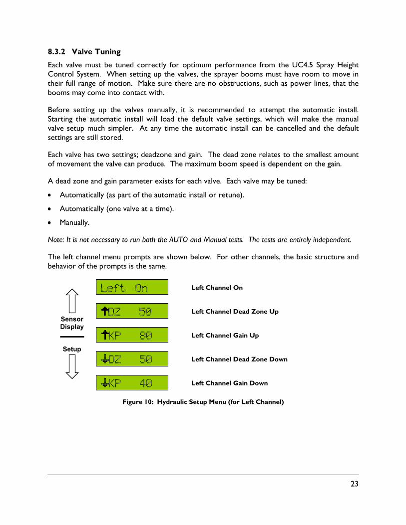
8.3.2 Valve Tuning
Each valve must be tuned correctly for optimum performance from the UC4.5 Spray Height Control System. When setting up the valves, the sprayer booms must have room to move in their full range of motion. Make sure there are no obstructions, such as power lines, that the booms may come into contact with.
Before setting up the valves manually, it is recommended to attempt the automatic install. Starting the automatic install will load the default valve settings, which will make the manual valve setup much simpler. At any time the automatic install can be cancelled and the default settings are still stored.
Each valve has two settings; deadzone and gain. The dead zone relates to the smallest amount of movement the valve can produce. The maximum boom speed is dependent on the gain.
A dead zone and gain parameter exists for each valve. Each valve may be tuned:
Automatically (as part of the automatic install or retune).
Automatically (one valve at a time).
Manually.
Note: It is not necessary to run both the AUTO and Manual tests. The tests are entirely independent.
The left channel menu prompts are shown below. For other channels, the basic structure and behavior of the prompts is the same.
Left Channel On
Left Channel Dead Zone Up
Left Channel Gain Up
Left Channel Dead Zone Down
Left Channel Gain Down
Figure 10: Hydraulic Setup Menu (for Left Channel)
KP 40
KP 80
Left On
DZ 50
DZ 50
Sensor Display
Setup
24
Automatic Dead Zone Calibration:
Follow Section 8.1.1 (level booms, working RPM, etc.) before proceeding.
Ensure the UC4.5 control panel is in manual mode, at the run screen.
Navigate to the "More?" menu prompt in the SETUP ( ) menu. Press to confirm.
Navigate to the boom section to be set up, for example "Left?" to adjust the left up or the left down settings. Press the button to confirm.
Press the button to access the next menu prompt. Choose the dead zone up or down setting (Figure 10).
Press and hold the button.
When the "Done" message is displayed, release the button to view the new setting.
Manual Dead Zone Calibration:
Follow Section 8.1.1 (level booms, working RPM, etc.) before proceeding.
Ensure the UC4.5 control panel is in manual mode, at the run screen.
Navigate to the "More?" menu prompt in the SETUP ( ) menu. Press to confirm.
Navigate to the boom section to be setup, for example, "Left?" to adjust the left up and/or the left down settings. Press the button to confirm.
Press the button to access the next menu prompt. Choose the dead zone up or down setting (Figure 10).
Press and hold the button.
The valve will turn on at the indicated setting for exactly one second. The screen will show the actual change in height.
The change in height reading is live as long as the button is held. Wait until the height reading has settled to a stable value and record this reading.
Average three readings. The acceptable average change in height should be from 0.5 to 1.5 inches (13 to 38 mm). Ideal would be 1 inch exactly (25 mm).
If the average is less, increase the DZ setting with the button. If the average is more, decrease the DZ setting with the button.
Repeat the manual dead zone test until the average falls into the acceptable range.
25
Automatic Gain Calibration:
Before tuning the gain setting, the dead zone for that function must be tuned. If the dead zone tuning has not been completed, follow the instructions for tuning a dead zone.
Follow Section 8.1.1 (level booms, working RPM, etc.) before proceeding.
Ensure the UC4.5 control panel is in manual mode, at the run screen.
Navigate to the "More?" menu prompt in the SETUP ( ) menu. Press to confirm.
Navigate to the boom section to be setup, for example, "Left?" to adjust the left up and/or the left down settings. Press the button to confirm.
Press the button to access the next menu prompt. Choose the gain up or down setting (Figure 10).
Press and hold the button.
When the "Done" message is displayed, release the button to view the new setting.
Manual Gain Calibration:
CAUTION
This test will drive the boom at full speed in the selected direction for one second. Make sure the boom has full range of movement and if driving the boom down, make sure it is not close to the ground.
The purpose of this test is to determine the sprayer boom speeds. It is recommended that each test be performed three times and the readings averaged.
From the speed measurements taken, use Table 2 to determine the appropriate gain values to use for each function. This test will provide approximate results for gain values. Proper gain values rely on more than just boom speed so it is highly recommended to use the automatic gain setup if possible.
Follow Section 8.1.1 (level booms, working RPM, etc.) before proceeding.
Ensure the UC4.5 control panel is in manual mode, at the run screen.
Navigate to the "More?" menu prompt in the SETUP ( ) menu. Press to confirm.
Navigate to the boom section to be setup, for example, "Left?" to adjust the left up and/or the left down settings. Press the button to confirm.
Press the button to access the next menu prompt. Choose the gain up or down setting (Figure 10).
Press and hold the button.
The valve will turn on at 100 percent speed for exactly one second, regardless of what the gain setting already is. The screen will show the actual change in height.

26
The change in height reading is live as long as the button is held. Wait until the height reading has settled to a stable value and record this reading. This is the boom speed in inches per second (in/s) or mm per second (mm/s).
Repeat the Manual Gain Test three times, repositioning the boom as necessary.
Average the three readings. Typical values are between 15 and 50 inches/sec.
Set the Gain value using the buttons using the tables below as a guideline. Right and left gain settings are polarized for direction as shown in Table 2.
Note: Gain values depend on many more factors than just speed, and therefore are best set automatically or by an experienced operator.
Note: Test the system in automatic mode at a sensitivity setting of five. The sensitivity setting will scale the gain settings. If the booms are not reacting quickly enough, a higher gain setting will make the boom respond faster. If the booms are too jerky or unstable, use a lower the gain setting or improve the boom’s mechanical damping.
Table 2: Gain Settings
Function Boom Speed (inch / sec)
Up Gain Down Gain
Left / Right 1 - 5 Too Slow Too Slow
Left / Right 5 - 15 225 - 175 100 - 70
Left / Right 15 - 25 175 - 150 70 - 50
Left / Right 25 - 40 150 - 100 50 - 30
Left / Right 40 - 70 100 - 50 30 - 15
Left / Right 70 + 50 - 1 15 - 1
Main (on / off) 1 - 5 100 - 75 100 - 75
Main (on / off) 5 - 10 75 - 50 75 - 50
Main (on / off) 10 - 15 50 - 30 50 - 30
Main (on / off) 15 - 20 30 - 15 30 - 15
Main (proportional) 1 - 5 85 - 75 85 - 75
Main (proportional) 5 - 10 75 - 66 75 - 66
Main (proportional) 10 - 15 66 - 60 66 - 60
Main (proportional) 15 - 20 60 - 53 60 - 53
Roll 1 - 10 254 - 225 254 - 225
Roll 10 - 15 225 - 175 225 - 175
Roll 15 - 20 175 - 150 175 - 150
Roll 20 + 150 - 100 150 - 100
27
8.3.3 Boom Geometry Tuning (Push Test)
If it desired to redo the push test or if the system has been manually set up and the boom geometry needs to be calibrated, the push test can manually launched.
To Manually Launch the Boom Geometry Test:
Navigate to the "More?" menu prompt in the SETUP ( ) menu. Press to confirm.
Navigate to "Roll?". Press to confirm.
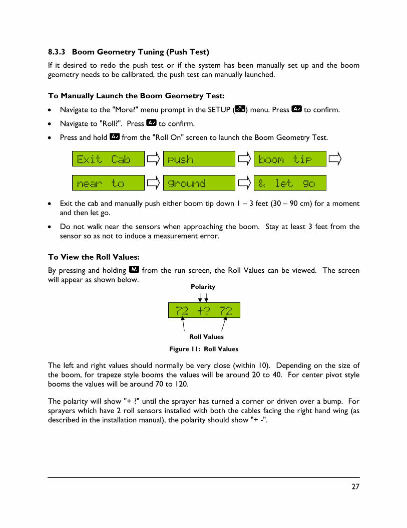
Press and hold from the "Roll On" screen to launch the Boom Geometry Test.
Exit the cab and manually push either boom tip down 1 – 3 feet (30 – 90 cm) for a moment and then let go.
Do not walk near the sensors when approaching the boom. Stay at least 3 feet from the sensor so as not to induce a measurement error.
To View the Roll Values:
By pressing and holding from the run screen, the Roll Values can be viewed. The screen will appear as shown below.
Figure 11: Roll Values
The left and right values should normally be very close (within 10). Depending on the size of the boom, for trapeze style booms the values will be around 20 to 40. For center pivot style booms the values will be around 70 to 120.
The polarity will show "+ ?" until the sprayer has turned a corner or driven over a bump. For sprayers which have 2 roll sensors installed with both the cables facing the right hand wing (as described in the installation manual), the polarity should show "+ -".
72 +? 72
& let go ground near to
boom tip push Exit Cab
Roll Values
Polarity

28
8.3.4 Turning Booms Off or On
The UC4.5 automatic height control can be turned off for each individual boom section. In automatic mode, boom sections that are turned off will not automatically adjust and are indicated with a "D" in the run screen, as shown in Figure 12.
Turning off the left channel, for example, will disable the left section’s automatic control; however, manual height readings from this section will still be available. The sprayer’s wing booms will still be controlled automatically.
Left Channel is turned off ("D" = Disabled)
Figure 12: Turning a Boom Off (for Left Channel)
Ensure the UC4.5 control panel is in manual mode and at the run screen.
Navigate to the "More?" menu prompt in the SETUP ( ) menu. Press to confirm.
Navigate to the boom section to be turned off or on, for example, "Left?". Press the button to confirm.
At the "Left On" menu prompt use the buttons to change the status.
Press and hold the or button for two seconds to return to the run screen.
D 45 A

29
8.4 Quick Install
The Quick Install feature of the UC4.5 Spray Height Control System is designed to help diagnose problems that cannot be identified during the Automatic Setup. It will instantly setup the system with typical values for hydraulic calibration and sprayer geometry, based on the sprayer type selected. Perform the following procedure for a Quick Install.
STANDARD SYSTEM (Including Passive Roll):
The system must have a minimum of two sensors.
Verify the sensors are installed with the lowest serial number on the left side increasing to the highest serial number on the right side.
Level the boom at 35 inches (90 cm) height.
Navigate in the setup menu to the "Install?" screen and press the button.
Use the buttons to toggle through a list of available sprayer types. The types are listed in Section 14.
Press and hold for 5 seconds.
When the word "Sensor" is displayed, release the button. The system will be configured with the standard settings based on the type selected and the number of sensors present.
The UC4.5 system will now prompt the operator to perform a push test (Section 8.1.6 - Boom Geometry Tuning).
Perform a ReTune (Section 8.2).
Sensor
Type +/- Select
AN2 ?
Install ?
30
ACTIVE ROLL SYSTEM:
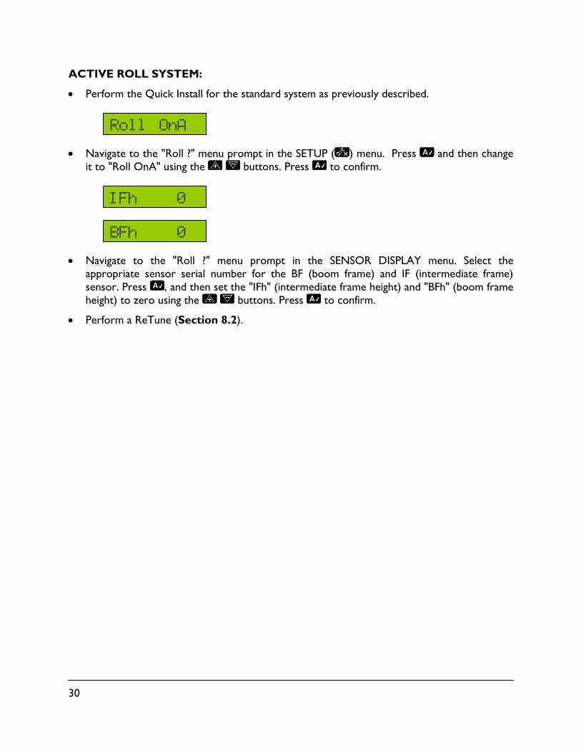
Perform the Quick Install for the standard system as previously described.
Navigate to the "Roll ?" menu prompt in the SETUP ( ) menu. Press and then change it to "Roll OnA" using the buttons. Press to confirm.
Navigate to the "Roll ?" menu prompt in the SENSOR DISPLAY menu. Select the appropriate sensor serial number for the BF (boom frame) and IF (intermediate frame) sensor. Press , and then set the "IFh" (intermediate frame height) and "BFh" (boom frame height) to zero using the buttons. Press to confirm.
Perform a ReTune (Section 8.2).
BFh 0
IFh 0
Roll OnA

31
9 Optional Kits
The kits shown below are optional add on kits for the UC4.5 Spray Height Control System. These kits will help improve the performance for certain situations described below.
9.1 Main Lift Kit
An additional sensor may be added to the centre section of the boom to improve system performance.
9.2 Severe Terrain Kit
Additional sensors may be added to improve boom protection and system performance.
This is more suitable for larger booms and in severe terrain conditions.
Figure 13: Example of Severe Terrain
9.3 Enhanced Stability Kit
This kit is designed to provide enhanced boom stability for sprayers which are loosely coupled between the intermediate frame (para-lift arms or mast) and the sprayer chassis.
The roll sensor included in this kit will provide an additional measurement of the sprayer dynamics to allow for greater stability of the boom.
32
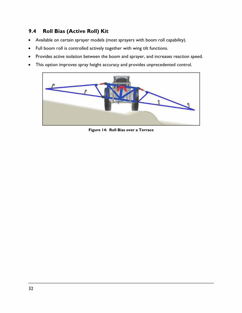
9.4 Roll Bias (Active Roll) Kit
Available on certain sprayer models (most sprayers with boom roll capability).
Full boom roll is controlled actively together with wing tilt functions.
Provides active isolation between the boom and sprayer, and increases reaction speed.
This option improves spray height accuracy and provides unprecedented control.
Figure 14: Roll Bias over a Terrace

33
10 Options
NOTE: Some options may not be available for all sprayer makes and models. Consult your sales representative or technical support with any questions or concerns.
10.1 Headland Assist
Headland Assist is used to raise the wings only or the entire boom at the end of the field for turning. This feature operates when the system is in automatic mode. This feature is enabled for certain sprayer types.
The headland mode height can be changed. While the boom is in headland assist mode, the operator can change the height by simply adjusting the target height (Section 6.3).
Navigating the Headland Assist & Remote Switch Menu:
Ensure the UC4.5 control panel is in manual mode and at the run screen.
Navigate to the "More?" menu prompt in the SETUP ( ) menu. Press to confirm.
Press until the display says "Other?". Press to confirm.
Use the buttons to navigate the Headland Assist menu.
The setting is selected when the Headland Assist menu is exited by pressing and holding .
To switch between the wings only mode and the main lift mode, press and hold at any time in the Headland Assist menu. Figure 15 shows the menu structure for the Headland Assist menu.
Figure 15: Headland Assist and Remote Switch Menu
RemS Off
RemS On
RemS HW1
RemS HW2
RemS HW3
RemS Off
RemS HM3
RemS HM2
RemS HM1
RemS On
+
–
Press & Hold Auto
34
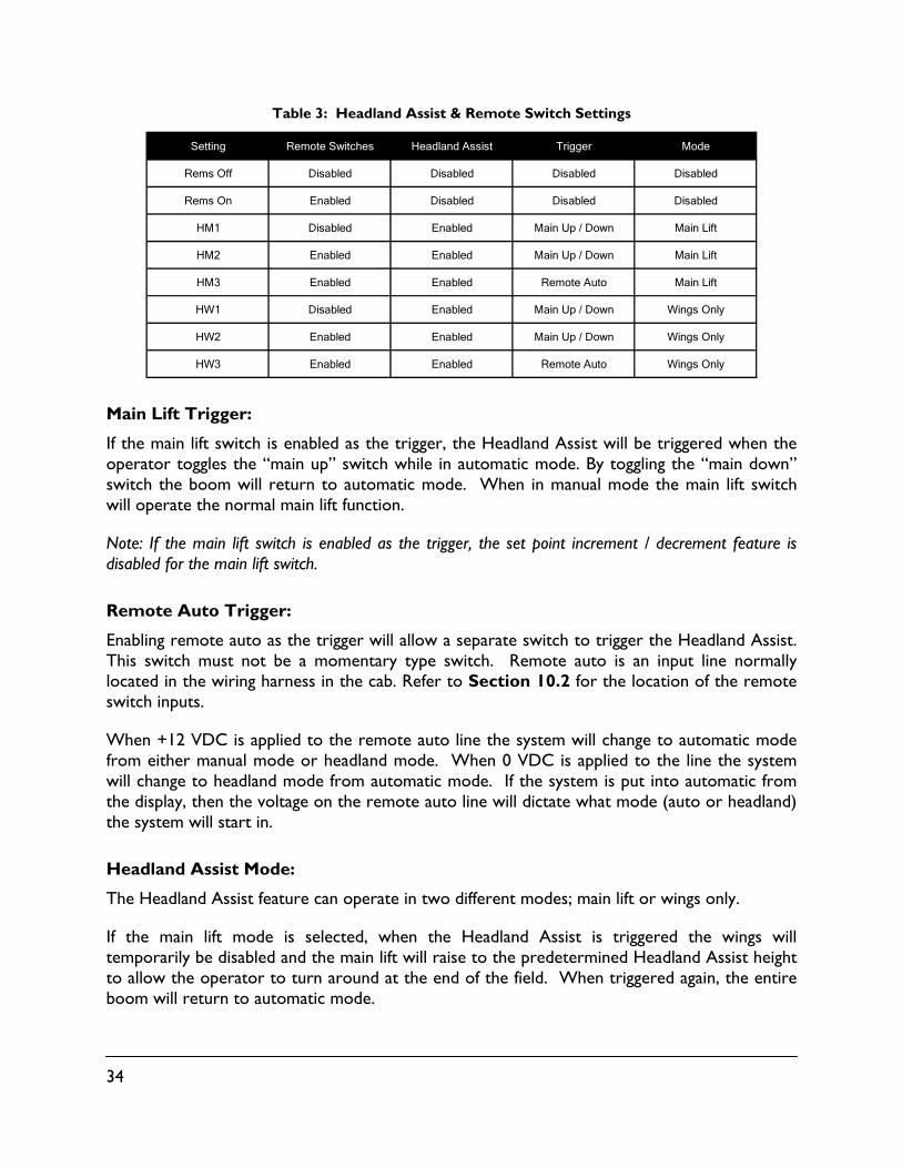
Table 3: Headland Assist & Remote Switch Settings
Setting Remote Switches Headland Assist Trigger Mode
Rems Off Disabled Disabled Disabled Disabled
Rems On Enabled Disabled Disabled Disabled
HM1 Disabled Enabled Main Up / Down Main Lift
HM2 Enabled Enabled Main Up / Down Main Lift
HM3 Enabled Enabled Remote Auto Main Lift
HW1 Disabled Enabled Main Up / Down Wings Only
HW2 Enabled Enabled Main Up / Down Wings Only
HW3 Enabled Enabled Remote Auto Wings Only
Main Lift Trigger:
If the main lift switch is enabled as the trigger, the Headland Assist will be triggered when the operator toggles the “main up” switch while in automatic mode. By toggling the “main down” switch the boom will return to automatic mode. When in manual mode the main lift switch will operate the normal main lift function.
Note: If the main lift switch is enabled as the trigger, the set point increment / decrement feature is disabled for the main lift switch.
Remote Auto Trigger:
Enabling remote auto as the trigger will allow a separate switch to trigger the Headland Assist. This switch must not be a momentary type switch. Remote auto is an input line normally located in the wiring harness in the cab. Refer to Section 10.2 for the location of the remote switch inputs.
When +12 VDC is applied to the remote auto line the system will change to automatic mode from either manual mode or headland mode. When 0 VDC is applied to the line the system will change to headland mode from automatic mode. If the system is put into automatic from the display, then the voltage on the remote auto line will dictate what mode (auto or headland) the system will start in.
Headland Assist Mode:
The Headland Assist feature can operate in two different modes; main lift or wings only.
If the main lift mode is selected, when the Headland Assist is triggered the wings will temporarily be disabled and the main lift will raise to the predetermined Headland Assist height to allow the operator to turn around at the end of the field. When triggered again, the entire boom will return to automatic mode.

35
If the wings only mode is selected; when the Headland Assist is triggered only the wings will raise to the Headland Assist height. When triggered again, the entire boom will return to automatic mode.
10.2 Remote Switches
When remote switches are enabled, the UC4.5 can be put into automatic or manual mode using a remote switch connected to the remote auto and manual input lines. This feature can still be used in conjunction with the remote auto line as the trigger in headland mode. The remote auto line is located on pin 1 of connector P16 (wire is hidden under spiral wrap) and the remote manual input line is located between pin 11 on connector P16 and pin 11 on connector P12 on cables 44650-50 and 44650-51. Please refer to the UC4.5 Installation Manual for detailed schematics of these cables.
To activate automatic mode, apply +12 VDC to the remote auto line. The voltage must always be applied after the display has been powered up. The UC4.5 will not go into automatic mode if voltage is applied to the remote auto input line before the system is powered up.
To activate manual mode, apply +12 VDC to the remote manual line. The remote manual function always has priority over the automatic function.
10.3 High Oil Temperature Alarm
The High Oil Temperature Alarm will sound if the Norac valve block reaches a temperature of 95° C. This alarm will only sound once and will not repeat. The alarm is re-enabled each time automatic mode is entered. If the alarm sounds, the screen will also show “VT Max” for 2 seconds to inform the operator that the valve block temperature is at a maximum.
This alarm is for informational purposes only, to indicate when there is a major oil heating issue with the machine. This alarm does not reflect the warranty of any components. Actual maximum oil temperature is determined by the fluid used in the system and should be recommended by the sprayer manufacturer.
10.4 Sensor Reading Alarm
Pressing and holding will enable / disable the sensor reading alarm. If enabled, the alarm will sound if an ultrasonic sensor has lost a reading. The alarm is defaulted to off.
10.5 Minimum Height Mode
Minimum height mode is normally used only for systems with five sensors (severe terrain kit). Since the five sensor system has two wing sensors that average the height, it is possible to have a boom tip close to the ground while still maintaining an acceptable average height. The minimum height defines the lowest height in which a single sensor on the wings is allowed to go.

36
To access the minimum height mode settings; press from the run screen until "More?" is displayed. Press to accept.
Press again until "Other?" is displayed. Press to accept.
Use the buttons to change the settings.
Minimum Height Soil Mode (default is 0)
Minimum Height Crop Mode (default is 0)
Units (cm or inches)
Figure 16: Minimum Height Mode and Units Menu
10.6 Changing the Units
To change the units, simply navigate to the units menu as shown in Figure 16. Use the buttons to change between inches and cm.
10.7 Valve and Air Temperature
Pressing and holding will cycle the display between the valve block temperature "VT" and the air temperature "AT".
Metric (cm height) = Celsius
Imperial (inch height) = Fahrenheit
MHC 0
MHS 0
Units in
Sensor Display
Setup

37
11 Maintenance
The NORAC Spray Height Control system requires very little maintenance, but there are a few procedures that will ensure the system continues to work correctly for many years.
Before each day:
It is highly recommended that the sprayer friction pads are greased. To ensure optimum performance this should be done daily. This will ensure the boom is pivoting separately from the sprayer. It is very important to keep the friction pads greased on Active Roll™ systems.
Ensure the height sensor breakaway brackets are functioning correctly. Apply grease to the moving parts if necessary, to ensure they return to center after a break-away occurs.
Ensure there is a clean, dry foam disc inserted in each sensor. If it is clogged with dust or other debris, clean it as described below.
At the end of the season:
Replace the oil filter in the NORAC hydraulic manifold annually (NORAC P/N 106285).
Cleaning Ultrasonic Height Sensors:
Remove the foam disc from the sensor and wash it with clean water. Squeeze out excess water and allow the foam disc to dry. The sensor can be used if the foam is wet, however a valid height reading may not be obtained until it is completely dry.
If the transducer inside the sensor is also dirty, wash it using clean water. Remove the sensor from the bracket and rinse debris from the transducer by pouring water across the face of the sensor. Do not submerge or pressure-wash the sensor. A soft bristle brush can also be used to gently clean the transducer if water alone is not sufficient. Use caution not to scratch or tear the transducer as it is fragile. The sensor should be left to dry with the transducer facing downwards. The sensor can be used if it is wet, however a valid height reading may not be obtained until it is completely dry. Leaving the control system powered on with the sensor connected and facing down will speed the process of drying the sensor.
Chemicals or compressed air should never be used to clean the sensor.

38
12 Troubleshooting
12.1 General Operation
Boom does not appear to be level after system setup:
The sensitivity setting may be too low. Check the sensor height readings, if it differs from the target height then try turning up the sensitivity. The default tolerance for a sensitivity setting of 5 is ± 6 cm (2.5 inches).
The dead zone may be calibrated incorrectly. If the dead zone is set too low the system cannot make small corrections. Recalibrate the dead zones as described in Section 8.3.2.
The sensor offset heights may be incorrect. Refer to Section 8.3.1.
The system will not go into automatic mode:
Ensure the system has completed an automatic install. If the automatic install was started and not finished, at least one hydraulic function (Section 8.3.2) will need to be manually tuned before the system will go into automatic mode.
The system resets when a valve is turned on:
Check the power supply. The sprayer’s power supply voltage must be more than 12 VDC.
This may also be caused by a damaged or defective power supply cable. Check the power cable for a good connection to the supply.
The system randomly switches between auto and manual mode:
This may be caused by a damaged or defective interface cable. Ensure all cables are connected correctly. The connections should be tight and free of corrosion.
There may be electrical noise on the sprayer’s DC system. Add a power line filter or freewheeling diodes on one or more of the sprayer’s solenoid valves.

39
12.2 Sensors
Height or roll sensor appears not to work (displays "NC" or "No Comm"):
"NC" or "No Comm" refers to no communication. This may be caused by a damaged or defective CANbus cable. Ensure all cables are connected correctly. The connections should be tight and free of corrosion.
Ensure the correct serial numbers are entered for each of the sensors (Section 8.3.1).
If the cables check out ok, the sensor may be damaged. Try swapping sensors to see if the problem follows the sensor.
Invalid height sensor measurement (displays "NR" or "NoRdg"):
"NR" and "NoRdg" refers to no reading. It is normal to see this message occasionally. If this message occurs all the time, the sensor may be having difficulty obtaining a proper reading. Ensure the sensor is not out of range. Check the sensor alignment. The sensor should point almost perpendicular to the ground and there should be no obstructions between the sensor and the ground.
The protective foam shield may be contaminated. Inspect and clean the foam shield. If it is severely worn or dirty replace the foam shield.
The sensor may have moisture in it. This can be common for sprayers which fold the wing tips up; therefore pointing the sensors into the air. If rain or moisture collects in the sensor, remove the protective foam disc and allow the water to drain out. Leaving the sensor running will help it dry out on its own and start working again.
The sensor transducer may be damaged. Remove the foam shield and check the sensor ticking. If the ticking sound cannot be heard or if it is very faint then the transducer may be damaged and the sensor may need repairing.
During power up the panel shows "1 Absent":
One of the configured sensors was not found during power up. One of the sensors is disconnected or not communicating.
Ensure the correct serial numbers are entered for each of the sensors (Section 8.3.1).

40
Sensor Swapping:
Swapping Sensors is a useful procedure for determining whether a sensor error message (e.g. "LO NC") is due to the sensor or the wiring to the sensor.
Note: A sensor may have power and emit a ticking sound, but have broken communication wire(s), which would cause this error. Performing Sensor Swapping would help determining the cause.
The procedure is as follows:
Exchange the affected sensor with one that is reporting correctly (e.g. "LO" and "RO").
Swap (input) their respective location serial numbers into the control panel (Section8.3.1).
If the problem still exists in the same location, the wiring from that branch may have a fault.
If the error appears in the new location, the sensor may not be functioning properly.
Sensor Alignment:
Proper sensor alignment is critical for proper UC4.5 performance.
When the boom is in its lowest position, the sensor mouth must be 22cm (9 inches) or more above the spray nozzles.
The bottom of the sensor must be at least 25cm (9 inches) in front of the nozzles.
The sensor must be approximately vertical at normal operating heights.
Ensure that there are no obstructions within a 30cm (12 inch) diameter circle projected directly below the sensor.
When mounting or relocating sensor brackets, ensure they do not interfere with boom folding operation.
When mounting to the top part of the boom (Figure 17), check that the sensor cannot read off the bottom part of the boom. This is most common in Crop Mode.
Figure 17: Sensor Reading Off the Boom
Sensor field of view
41
12.3 Hydraulics
When diagnosing hydraulic problems, first determine if the electrical system is ok. Check all cable connections and ensure they are tight and free of corrosion. Measure the electrical output at the valve to ensure there is voltage at the connection.
Most valves will have an override pin. This is a small brass colored hole located at the end of each coil in the center. There will be one for each valve. Pushing in the pin will manually activate the valve. There must be pressure at the block for the function to move.
If the sprayer is equipped with a bypass valve it will need to be activated anytime a hydraulic function is required.
Boom(s) will not raise or lower:
Ensure there is hydraulic oil being supplied at the Norac valve block and that there is pressure at the pressure port. The hydraulics will not work if the pressure and tank lines are reversed. If there are any quick couplers in the system they must be properly connected.
The raise and lower lines to the tilt cylinders may be reversed. Ensure the raise lines are connected to the "B" ports on the Norac valve block. The lower lines should be connected to the "A" ports.
The boom will raise when it should lower, or vice versa:
Check the cable connections to the valve block and ensure they are not reversed.
The raise and lower lines to the tilt cylinders may be reversed. Ensure the raise lines are connected to the "B" ports on the Norac valve block. The lower lines should be connected to the "A" ports.
The boom will creep up or down in manual mode:
The raise and lower lines to the tilt cylinders may be reversed. Ensure the raise lines are connected to the "B" ports on the Norac valve block. The lower lines should be connected to the "A" ports.
This may be caused by a problem with the sprayer’s hydraulic system. Check the sprayer hydraulics. Check if the tilt cylinders are leaking and replace the seals if needed.
There may be an internal problem with the Norac valve block. Some possible causes are; a sticky valve, worn valve, faulty check valves or a foreign object stuck in the valve block. If possible try removing any foreign objects in the valve. The valve block may need also repairing.

42
The hydraulic oil is overheating:
Using the UC4.5 system at higher sensitivities may create a greater demand on the sprayer’s hydraulics. Try lowering the sensitivity.
Plumbing single acting systems as double acting with orifices in both "A" ports may reduce the heating.

43
12.4 Boom Stability
The boom is unstable in automatic mode:
Ensure the sprayer’s boom suspension is operating correctly and moving freely. If the suspension is sticking or too loose the boom will be unstable. If the boom is unstable in manual mode, the height control system will not make it more stable.
If there are friction pads on the boom, ensure they are well greased. Check the boom damper shocks and replace them if they are worn. If there is substantial wear in the mast-style main lift, the boom will be too loose. Install shims or adjust the mast-style lift if possible.
If the hydraulic settings are not calibrated correctly the boom may be unstable. Perform a Retune (Section 8.2) and redo the Boom Geometry Test (Section 8.3.3).
Check the mounting of the roll sensors. They must be mounted for the type of boom suspension as shown in the installation manual.
Ensure the height sensors are reading properly and consistently. The sensors must be aligned and mounted correctly. The sensor should point almost perpendicular to the ground and there should be no obstructions between the sensor and the ground.
If the sprayer is equipped with accumulators on the tilt cylinders they should be charged to the manufacturers specifications. There should also be orifices installed between the accumulators and tilt cylinders.
The boom(s) move all the way to the top in crop mode:
The sensors are likely reading off of the boom in crop mode. Ensure the sensors are aligned and mounted correctly. The sensor should point almost perpendicular to the ground and there should be no obstructions between the sensor and the ground.
44
12.5 Setup Messages
The following are descriptions of messages or problems that may be encountered during the automatic setup or retune.
"Timeout":
This message may occur if the system is trying to move a boom but does not see any change in the sensor heights. If the cylinder is fully extended or retracted, manually reposition the boom into the middle of the stroke and resume the setup by holding the button.
For left and right booms that do not adjust below the level of the main boom, ensure that the main boom is within 125cm (50 inches) above ground before attempting an Install or ReTune.
Ensure there is enough hydraulic pressure to move the boom.
"Mot’n Dly":
The system detects motion and is waiting for the boom to stop moving.
"Wiring!":
This message is shown at the wiring test if the system receives a signal from the wrong sprayer switch. This will occur if the wiring is incorrect or there is a poor cable connection. Pressing the wrong switch during this test will also display this error message.
"Too Many":
The system has detected too many sensors connected. Remove the additional sensors or set up the system manually.
"Bakwards":
This message will be shown if the boom moves in the wrong direction of what is expected by the UC4.5 system. This may be caused by a wiring or hydraulic problem. An extremely under damped boom or high wind conditions may also cause this message to appear.
"TooHigh!" or "TooLow!":
The boom is positioned higher than 60 inches (150 cm) or lower than 30 inches (80 cm). The system setup was likely started with the boom too high or too low. Restart the setup with the boom positioned at 35 inches (90 cm).
45
The display is stuck at "Mot’n Dly" or "KP Stp 9" during an install or retune:
The sensor may be reading off the boom. Try moving the sensor to a better location.
The target may be too weak. Move the sprayer to a better location with either dirt orgravel on the ground. Ensure there is no grass or other plants under the sprayer boom.
The sensor may be out of range. Release the button and manually adjust the entire boom to approximately 35 inches (90 cm) above the ground. Press and hold to continue with the install or retune.
It may be too windy outside too complete an Install or Retune. If the boom cannot stopmoving due to high wind conditions, the system cannot be properly calibrated.

46
12.6 Operational Messages
The following messages may appear during normal operation and may not indicate an error with the system.
"NR" or "NoRdg":
This indicates the sensor is not receiving a good reading. It is normal to see this messageoccasionally, however if the message is constantly displayed there may be a problem with asensor. Refer to Section 12.2 for more information.
"Minimum Overide":
This message is displayed when the target height is lower than the Minimum Height Modeallows.
"Disabled":
Access to the system setup features (Automatic Install, ReTune) has been disabled by theinstaller to avoid unintentional system changes.
">>>>>>>>":
The control panel is busy with a task that may take a few seconds. Wait for the arrows todisappear before activating any control panel switches.

47
13 Statement of Limited Warranty
NORAC SYSTEMS INTERNATIONAL INC., also known as NORAC, warrants all equipment of its manufacture to be free of defects in material and workmanship for a period of one year. This warranty period is for a period of twelve months from the date the equipment is delivered by NORAC or its authorized dealer to the purchaser. Items include control systems and genuine replacement parts manufactured by NORAC. Auxiliary components not manufactured by NORAC or NORAC rebuilt parts are covered by a 90-day warranty.
NORAC will repair free of charge items returned within the warranty period to one of NORAC’s authorized service centers. In countries where NORAC maintains authorized service centers, freight will be paid one way and returned by the same carrier unless instructed differently. The purchaser is responsible that the item is properly packaged for shipment. Shipping damage is not covered under this warranty.
NORAC or its authorized Service Center will repair or replace, at its option, any defective part or component at no cost to the purchaser during the Warranty period. If service in the field is required NORAC will authorize on-site repairs at no charge for parts and labor. Travel time, travel costs and per diem expenses to and from the place where repairs are made, will not be covered by this warranty.
For the nearest Service Center visit our website at www.norac.ca or call +1 306 664 6711 or e-mail [email protected].
Any evidence of, negligent or abnormal use, alteration of serial numbers, or repairs attempted by other than NORAC authorized personnel or not using NORAC certified or recommended parts, automatically voids the warranty. Normal wear is not covered under this warranty.
NORAC will not warranty any complaints relating to inadequate installation (unless the installation was performed by NORAC), adjustments or calibration.
The forgoing states the entire liability of NORAC regarding the purchase and use of its equipment. The purchaser agrees that NORAC accepts no liability for any consequential loss or damage of any kind. The purchaser further agrees that the warranties contained herein are in lieu of all other warranties, expressed or implied, and, specifically NORAC disclaims any implied warranty regarding merchantability or fitness for a particular purpose. This paragraph is of no force or effect in those jurisdictions, where the limitations of the type noted herein are prohibited by law.
To ensure warranty coverage the customer must register within 30 days of their purchase by either sending in a registration form included with the equipment or online at www.norac.ca.
48
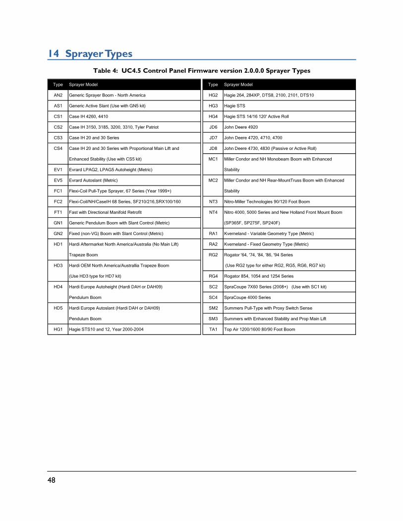
14 Sprayer Types
Table 4: UC4.5 Control Panel Firmware version 2.0.0.0 Sprayer Types
Type Sprayer Model Type Sprayer Model
AN2 Generic Sprayer Boom - North America HG2 Hagie 264, 284XP, DTS8, 2100, 2101, DTS10
AS1 Generic Active Slant (Use with GN5 kit) HG3 Hagie STS
CS1 Case IH 4260, 4410 HG4 Hagie STS 14/16 120' Active Roll
CS2 Case IH 3150, 3185, 3200, 3310, Tyler Patriot JD6 John Deere 4920
CS3 Case IH 20 and 30 Series JD7 John Deere 4720, 4710, 4700
CS4 Case IH 20 and 30 Series with Proportional Main Lift and JD8 John Deere 4730, 4830 (Passive or Active Roll)
Enhanced Stability (Use with CS5 kit) MC1 Miller Condor and NH Monobeam Boom with Enhanced
EV1 Evrard LPAG2, LPAG5 Autoheight (Metric) Stability
EV5 Evrard Autoslant (Metric) MC2 Miller Condor and NH Rear-MountTruss Boom with Enhanced
FC1 Flexi-Coil Pull-Type Sprayer, 67 Series (Year 1999+) Stability
FC2 Flexi-Coil/NH/CaseIH 68 Series, SF210/216,SRX100/160 NT3 Nitro-Miller Technologies 90/120 Foot Boom
FT1 Fast with Directional Manifold Retrofit NT4 Nitro 4000, 5000 Series and New Holland Front Mount Boom
GN1 Generic Pendulum Boom with Slant Control (Metric) (SP365F, SP275F, SP240F)
GN2 Fixed (non-VG) Boom with Slant Control (Metric) RA1 Kverneland - Variable Geometry Type (Metric)
HD1 Hardi Aftermarket North America/Australia (No Main Lift) RA2 Kverneland - Fixed Geometry Type (Metric)
Trapeze Boom RG2 Rogator '64, '74, '84, '86, '94 Series
HD3 Hardi OEM North America/Australlia Trapeze Boom (Use RG2 type for either RG2, RG5, RG6, RG7 kit)
(Use HD3 type for HD7 kit) RG4 Rogator 854, 1054 and 1254 Series
HD4 Hardi Europe Autoheight (Hardi DAH or DAH09) SC2 SpraCoupe 7X60 Series (2008+) (Use with SC1 kit)
Pendulum Boom SC4 SpraCoupe 4000 Series
HD5 Hardi Europe Autoslant (Hardi DAH or DAH09) SM2 Summers Pull-Type with Proxy Switch Sense
Pendulum Boom SM3 Summers with Enhanced Stability and Prop Main Lift
HG1 Hagie STS10 and 12, Year 2000-2004 TA1 Top Air 1200/1600 80/90 Foot Boom
49
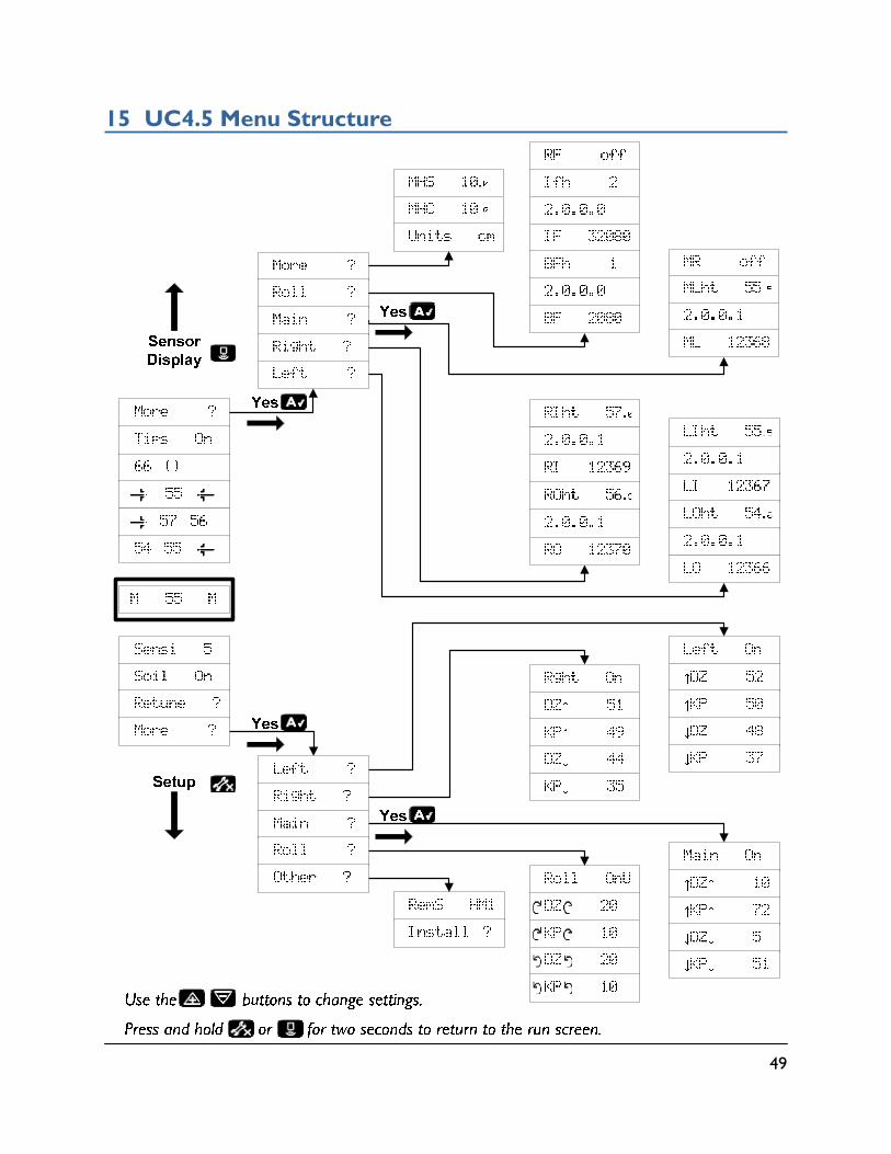
15 UC4.5 Menu Structure

TOPCON Agriculture Canada 3702 Kinnear Place
Saskatoon, SK S7P 0A6
TOPCON Agriculture Americas W5527 Hwy 106
Fort Atkinson, WI 53538
TOPCON Precision Agriculture Europe Avenida de la industria,
35, Tres Cantos, España Spain
Support Phone: 888 979 9509
E-mail: [email protected]: www.norac.ca


![Automatic Warning System (AWS) [Compatibility Mode]](https://static.fdocuments.us/doc/165x107/5571ff1f49795991699caf56/automatic-warning-system-aws-compatibility-mode.jpg)