
Operator Manual Kodak X-Omat 5000 RA Processor · Identifying the Covers and Panels and Other...
88
© Eastman Kodak Company Publication No. 5B6729 May 1997 Supersedes January 1996 OPERATOR MANUAL for the Kodak X-Omat 5000 RA Processor H148_0004AA
Transcript of Operator Manual Kodak X-Omat 5000 RA Processor · Identifying the Covers and Panels and Other...
© Eastman Kodak Company
Publication No. 5B6729May 1997
Supersedes January 1996
OPERATOR MANUALfor the
Kodak X-Omat 5000 RA Processor
H148_0004AA
2 May 1997 – 5B6729
PLEASE NOTE The information contained herein is based on the experience and knowledge relating to thesubject matter gained by Eastman Kodak Company prior to publication.
No patent license is granted by this information.
Eastman Kodak Company reserves the right to change this information without notice, andmakes no warranty, express or implied, with respect to this information. Kodak shall not be liablefor any loss or damage, including consequential or special damages, resulting from any use ofthis information, even if loss or damage is caused by Kodak’s negligence or other fault.
WarningTo avoid hazardous conditions, keep floors and floor coverings around your Kodak X-Omat Processor andassociated drains clean and dry at all times. Any accumulation of fluids from mixing tanks, drain lines, etc, shouldbe cleaned up immediately. In the event of an accumulation of liquid due to backup, overflow, or other malfunctionsof the drain associated with your Kodak X-Omat Processor, call a plumber or other contractor to correct any problemwith the drain. Kodak accepts no responsibility or liability whatsoever for the serviceability of any drain connected toor associated with a Kodak X-Omat Processor. Such drains are the sole responsibility of the customer.
Description Page
Table of Contents
Introduction . . . . . . . . . . . . . . . . . . . . . . . . . . . . . . . . . . . . . . . . . . . . . . . . . . . . . . . . . . . . 4Intended Audience . . . . . . . . . . . . . . . . . . . . . . . . . . . . . . . . . . . . . . . . . . . . . . . 4How To Use this Manual . . . . . . . . . . . . . . . . . . . . . . . . . . . . . . . . . . . . . . . . . . 4
Overview . . . . . . . . . . . . . . . . . . . . . . . . . . . . . . . . . . . . . . . . . . . . . . . . . . . . . . . . . . . . . . 5Product Description . . . . . . . . . . . . . . . . . . . . . . . . . . . . . . . . . . . . . . . . . . . . . . 5Identifying the Covers and Panels and Other Components of the Processor . . 6Using the Display Panel . . . . . . . . . . . . . . . . . . . . . . . . . . . . . . . . . . . . . . . . . . . 7Adjusting the Contrast of the Display Panel . . . . . . . . . . . . . . . . . . . . . . . . . . . 8Enabling the Auto Dimming Feature . . . . . . . . . . . . . . . . . . . . . . . . . . . . . . . . 8Adjusting the Intensity of the Interface Control Panel . . . . . . . . . . . . . . . . . . . . 8Using the Access Code . . . . . . . . . . . . . . . . . . . . . . . . . . . . . . . . . . . . . . . . . . . 9Changing the Access Code . . . . . . . . . . . . . . . . . . . . . . . . . . . . . . . . . . . . . . . . 9Limiting Access to the Processor Setup. . . . . . . . . . . . . . . . . . . . . . . . . . . . . . . 11Changing the User Access . . . . . . . . . . . . . . . . . . . . . . . . . . . . . . . . . . . . . . . . 11Operating Characteristics. . . . . . . . . . . . . . . . . . . . . . . . . . . . . . . . . . . . . . . . . . 12
Operating Instructions . . . . . . . . . . . . . . . . . . . . . . . . . . . . . . . . . . . . . . . . . . . . . . . . . . . . 13Performing the Daily Start-Up Procedure. . . . . . . . . . . . . . . . . . . . . . . . . . . . . . 13Performing the Shutdown Procedure . . . . . . . . . . . . . . . . . . . . . . . . . . . . . . . . 14Film Feeding. . . . . . . . . . . . . . . . . . . . . . . . . . . . . . . . . . . . . . . . . . . . . . . . . . . . 15
Default Setpoints and Configurations. . . . . . . . . . . . . . . . . . . . . . . . . . . . . . . . . . . . . . . . . 17Summary of Default Settings . . . . . . . . . . . . . . . . . . . . . . . . . . . . . . . . . . . . . . . . . . . . . . 17Basic Setup Options. . . . . . . . . . . . . . . . . . . . . . . . . . . . . . . . . . . . . . . . . . . . . . . . . . . . . . 19
Selecting a Film Processing Cycle . . . . . . . . . . . . . . . . . . . . . . . . . . . . . . . . . . . . . . 19Procedure for Selecting the Rapid, Standard, or Extended Cycle: . . . . . . . . . . 20Procedure for Selecting the K/RA Cycle: . . . . . . . . . . . . . . . . . . . . . . . . . . . . . 20
Setting the Dryer Setpoint Temperature . . . . . . . . . . . . . . . . . . . . . . . . . . . . . . . . . . 22Setting the Time and Date . . . . . . . . . . . . . . . . . . . . . . . . . . . . . . . . . . . . . . . . . . . . . 23Displaying the Time and Date . . . . . . . . . . . . . . . . . . . . . . . . . . . . . . . . . . . . . . . . . . 25Calibrating the Replenishment System . . . . . . . . . . . . . . . . . . . . . . . . . . . . . . . . . . . 26Selecting a Replenishment Mode . . . . . . . . . . . . . . . . . . . . . . . . . . . . . . . . . . . . . . . 28Selecting the Standby Mode . . . . . . . . . . . . . . . . . . . . . . . . . . . . . . . . . . . . . . . . . . . 30

5B6729 – May 1997 3
Setting the Volume of the Alarm. . . . . . . . . . . . . . . . . . . . . . . . . . . . . . . . . . . . . . . . . 32Selecting Temperature Lockout Mode . . . . . . . . . . . . . . . . . . . . . . . . . . . . . . . . . . . . 34Selecting Display Units . . . . . . . . . . . . . . . . . . . . . . . . . . . . . . . . . . . . . . . . . . . . . . . . 36Selecting the Receptacle Mode . . . . . . . . . . . . . . . . . . . . . . . . . . . . . . . . . . . . . . . . . 37Selecting the Display Language . . . . . . . . . . . . . . . . . . . . . . . . . . . . . . . . . . . . . . . . . 39
Advanced Setup Options . . . . . . . . . . . . . . . . . . . . . . . . . . . . . . . . . . . . . . . . . . . . . . . . . . 41Setting the Developer and Fixer Setpoint Temperatures . . . . . . . . . . . . . . . . . . . . . . 41Displaying the Fixer Temperature. . . . . . . . . . . . . . . . . . . . . . . . . . . . . . . . . . . . . . . . 43Setting the Developer and Fixer Replenishment Volumes . . . . . . . . . . . . . . . . . . . . . 44Verifying the Replenishment Rates . . . . . . . . . . . . . . . . . . . . . . . . . . . . . . . . . . . . . . 46Setting the Transport Speed. . . . . . . . . . . . . . . . . . . . . . . . . . . . . . . . . . . . . . . . . . . . 47Setting the Automatic On and Off Timers . . . . . . . . . . . . . . . . . . . . . . . . . . . . . . . . . . 49
Procedure for Setting Timer1 Initially . . . . . . . . . . . . . . . . . . . . . . . . . . . . . . . . . 49Setting the On Time: . . . . . . . . . . . . . . . . . . . . . . . . . . . . . . . . . . . . . . . . . . 50Setting the Off Time: . . . . . . . . . . . . . . . . . . . . . . . . . . . . . . . . . . . . . . . . . . 51
Procedure for Setting Timer2 Initially . . . . . . . . . . . . . . . . . . . . . . . . . . . . . . . . . 52Procedure for Setting the On and Off Timers for the Remaining Days of the Week 52
Copying On and Off Timer Settings: . . . . . . . . . . . . . . . . . . . . . . . . . . . . . . 52Setting Different On and Off Times for the Remaining Days: . . . . . . . . . . . 52
Changing the On and Off Timer Settings . . . . . . . . . . . . . . . . . . . . . . . . . . . . . . 54Selecting the Start-Up Option . . . . . . . . . . . . . . . . . . . . . . . . . . . . . . . . . . . . . . . . . . . 56Entering and Exiting Sleep Mode . . . . . . . . . . . . . . . . . . . . . . . . . . . . . . . . . . . . . . . . 57
Procedure for Entering Sleep Mode: . . . . . . . . . . . . . . . . . . . . . . . . . . . . . . . . . 58Procedure for Exiting Sleep Mode: . . . . . . . . . . . . . . . . . . . . . . . . . . . . . . . . . . 58
Selecting Sleep Mode Options . . . . . . . . . . . . . . . . . . . . . . . . . . . . . . . . . . . . . . . . . . 59Procedure for Turning On or Off the Roller Jog Option: . . . . . . . . . . . . . . . . . . 59Procedure for Turning On or Off the Cool Down Option: . . . . . . . . . . . . . . . . . . 61
Usage Information . . . . . . . . . . . . . . . . . . . . . . . . . . . . . . . . . . . . . . . . . . . . . . . . . . . . . . . 62Obtaining the Developer Usage Volume . . . . . . . . . . . . . . . . . . . . . . . . . . . . . . . . . . 62Obtaining the Developer Usage Rate . . . . . . . . . . . . . . . . . . . . . . . . . . . . . . . . . . . . . 63Obtaining the Fixer Usage Volume. . . . . . . . . . . . . . . . . . . . . . . . . . . . . . . . . . . . . . . 65Obtaining the Fixer Usage Rate . . . . . . . . . . . . . . . . . . . . . . . . . . . . . . . . . . . . . . . . . 66Selecting the Film Size for Each Setup Group . . . . . . . . . . . . . . . . . . . . . . . . . . . . . . 68Obtaining Film Usage Rates. . . . . . . . . . . . . . . . . . . . . . . . . . . . . . . . . . . . . . . . . . . . 69Obtaining the Processor’s Software Version . . . . . . . . . . . . . . . . . . . . . . . . . . . . . . . 71Other Functions . . . . . . . . . . . . . . . . . . . . . . . . . . . . . . . . . . . . . . . . . . . . . . . . . . . . . 72
Replenishment Solutions . . . . . . . . . . . . . . . . . . . . . . . . . . . . . . . . . . . . . . . . . . . . . . . . . . 73Mixing the Developer and Fixer Solutions . . . . . . . . . . . . . . . . . . . . . . . . . . . . . . . . 73Filling the Processor Tanks . . . . . . . . . . . . . . . . . . . . . . . . . . . . . . . . . . . . . . . . . . . . 73Draining the Processor Tanks . . . . . . . . . . . . . . . . . . . . . . . . . . . . . . . . . . . . . . . . . . 75
Menu Flowchart . . . . . . . . . . . . . . . . . . . . . . . . . . . . . . . . . . . . . . . . . . . . . . . . . . . . . . . . . 77
Preventive Maintenance . . . . . . . . . . . . . . . . . . . . . . . . . . . . . . . . . . . . . . . . . . . . . . . . . . . 81
Problem Solving . . . . . . . . . . . . . . . . . . . . . . . . . . . . . . . . . . . . . . . . . . . . . . . . . . . . . . . . . 83
Warranty . . . . . . . . . . . . . . . . . . . . . . . . . . . . . . . . . . . . . . . . . . . . . . . . . . . . . . . . . . . . . . . 85
Publication History . . . . . . . . . . . . . . . . . . . . . . . . . . . . . . . . . . . . . . . . . . . . . . . . . . . . . . . 87
OPERATORS MANUAL
4 May 1997 – 5B6729
Introduction
Intended AudienceThis manual is written for all users of the Kodak X-Omat 5000 RA Processor. The novice user needsonly a basic working knowledge of automatic radiographic film processors in order to understand theinstructions and procedures outlined in this manual. The experienced user may only need to refer tothis manual when using some of the features and functions new to the 5000 RA Processor.
How To Use this ManualThe manual is organized by topics. Each topic contains all the information you need to perform thegiven task:
• instructions for navigating through the required menus
• sample menu displays that appear after each key selection
5B6729 – May 1997 5
Overview
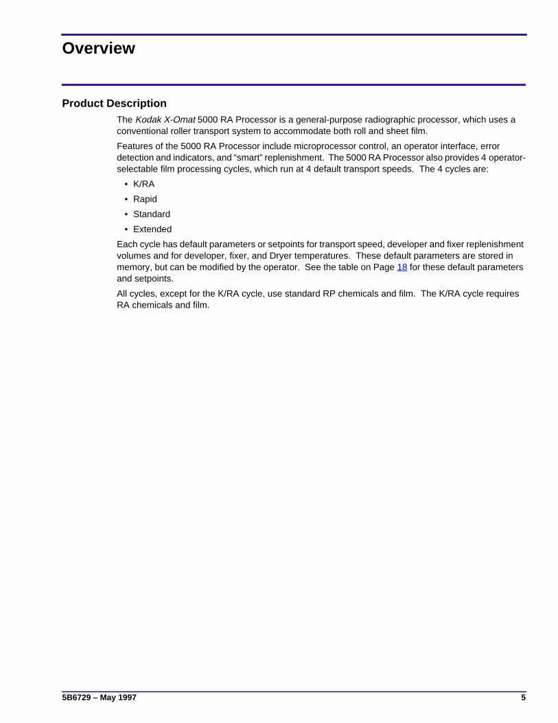
Product DescriptionThe Kodak X-Omat 5000 RA Processor is a general-purpose radiographic processor, which uses aconventional roller transport system to accommodate both roll and sheet film.
Features of the 5000 RA Processor include microprocessor control, an operator interface, errordetection and indicators, and “smart” replenishment. The 5000 RA Processor also provides 4 operator-selectable film processing cycles, which run at 4 default transport speeds. The 4 cycles are:
• K/RA
• Rapid
• Standard
• Extended
Each cycle has default parameters or setpoints for transport speed, developer and fixer replenishmentvolumes and for developer, fixer, and Dryer temperatures. These default parameters are stored inmemory, but can be modified by the operator. See the table on Page 18 for these default parametersand setpoints.
All cycles, except for the K/RA cycle, use standard RP chemicals and film. The K/RA cycle requiresRA chemicals and film.

OPERATORS MANUAL
6 May 1997 – 5B6729
Identifying the Covers and Panels and Other Components of the Processor
Figure 1 Receive and Feed Ends of the Processor
Figure 2 Circuit Breaker, Safelight Receptacle, and Interface Control Panel
H148_0061BAH148_0061BCA
PanelAccessMiddle
Access PanelTransformer
Side PanelNon - Drive
BinReceiving
PanelDisplay
Top CoverTrayFeed
Dryer AccessPanel
Electrical BoxAccess Panel
H148_0108CA
K R S E
P.I.C. INTERFACE
Sleep/
PanelControlInterface
Breaker CB1Main Circuit
ReceptacleSafelight
Status IndicatorsCycle Indicators
H148_0108CCA
WakeKey
CycleKey
5B6729 – May 1997 7
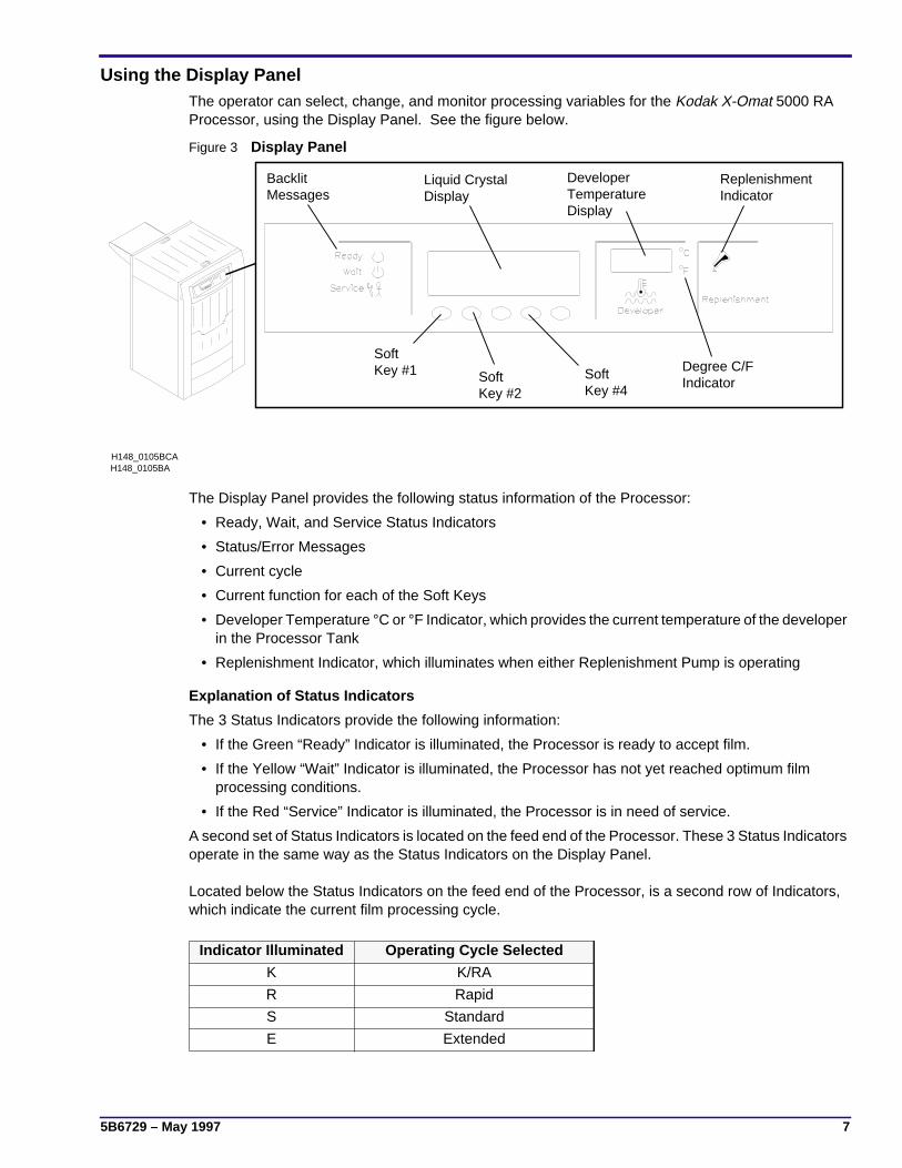
Using the Display PanelThe operator can select, change, and monitor processing variables for the Kodak X-Omat 5000 RAProcessor, using the Display Panel. See the figure below.
Figure 3 Display Panel
The Display Panel provides the following status information of the Processor:
• Ready, Wait, and Service Status Indicators
• Status/Error Messages
• Current cycle
• Current function for each of the Soft Keys
• Developer Temperature °C or °F Indicator, which provides the current temperature of the developerin the Processor Tank
• Replenishment Indicator, which illuminates when either Replenishment Pump is operating
Explanation of Status Indicators
The 3 Status Indicators provide the following information:
• If the Green “Ready” Indicator is illuminated, the Processor is ready to accept film.
• If the Yellow “Wait” Indicator is illuminated, the Processor has not yet reached optimum filmprocessing conditions.
• If the Red “Service” Indicator is illuminated, the Processor is in need of service.
A second set of Status Indicators is located on the feed end of the Processor. These 3 Status Indicatorsoperate in the same way as the Status Indicators on the Display Panel.
Located below the Status Indicators on the feed end of the Processor, is a second row of Indicators,which indicate the current film processing cycle.
Indicator Illuminated Operating Cycle Selected
K K/RA
R Rapid
S Standard
E Extended
H148_0105BAH148_0105BCA
BacklitMessages
Liquid CrystalDisplay
DeveloperTemperatureDisplay
ReplenishmentIndicator
SoftKey #1 Soft
Key #2SoftKey #4
Degree C/FIndicator
OPERATORS MANUAL
8 May 1997 – 5B6729
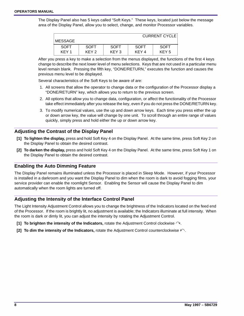
The Display Panel also has 5 keys called “Soft Keys.” These keys, located just below the messagearea of the Display Panel, allow you to select, change, and monitor Processor variables.
After you press a key to make a selection from the menus displayed, the functions of the first 4 keyschange to describe the next lower level of menu selections. Keys that are not used in a particular menulevel remain blank. Pressing the fifth key, “DONE/RETURN,” executes the function and causes theprevious menu level to be displayed.
Several characteristics of the Soft Keys to be aware of are:
1. All screens that allow the operator to change data or the configuration of the Processor display a“DONE/RETURN” key, which allows you to return to the previous screen.
2. All options that allow you to change data, configuration, or affect the functionality of the Processortake effect immediately after you release the key, even if you do not press the DONE/RETURN key.
3. To modify numerical values, use the up and down arrow keys. Each time you press either the upor down arrow key, the value will change by one unit. To scroll through an entire range of valuesquickly, simply press and hold either the up or down arrow key.
Adjusting the Contrast of the Display Panel[1] To lighten the display, press and hold Soft Key 4 on the Display Panel. At the same time, press Soft Key 2 on
the Display Panel to obtain the desired contrast.
[2] To darken the display, press and hold Soft Key 4 on the Display Panel. At the same time, press Soft Key 1 onthe Display Panel to obtain the desired contrast.
Enabling the Auto Dimming FeatureThe Display Panel remains illuminated unless the Processor is placed in Sleep Mode. However, if your Processoris installed in a darkroom and you want the Display Panel to dim when the room is dark to avoid fogging films, yourservice provider can enable the roomlight Sensor. Enabling the Sensor will cause the Display Panel to dimautomatically when the room lights are turned off.
Adjusting the Intensity of the Interface Control PanelThe Light Intensity Adjustment Control allows you to change the brightness of the Indicators located on the feed endof the Processor. If the room is brightly lit, no adjustment is available; the Indicators illuminate at full intensity. Whenthe room is dark or dimly lit, you can adjust the intensity by rotating the Adjustment Control.
[1] To brighten the intensity of the Indicators, rotate the Adjustment Control clockwise .
[2] To dim the intensity of the Indicators, rotate the Adjustment Control counterclockwise .
MESSAGECURRENT CYCLE
SOFTKEY 1
SOFTKEY 2
SOFTKEY 3
SOFTKEY 4
SOFTKEY 5

5B6729 – May 1997 9
Using the Access CodeOnly service personnel and one primary person should have use of the access code. The defaultaccess code 4213 is required to perform certain functions.
Simply press the “GO TO SETUP” key on the Walk-Up Menu and enter the access code to performthe functions listed below:
• to change setup information preset at the factory
• to change to or from the “K/RA” cycles
If the Limited Access Feature is off, an access code is not necessary to perform the functions listedbelow:
• to select the Processor cycle (except “K/RA”)
• to change the Dryer temperature
• to display the current fixer temperature
• to place the Processor in Sleep mode
• to display the time and date
The access code can be changed at any time by the user. To change the access code, follow theprocedure below. If you forget the new access code and need to revert to the original access code,call your service provider.
Changing the Access Code[1] From the Walk-Up Menu, press the “GO TO SETUP” key.
[2] Enter the 4-digit access code.
[3] Press the “MORE” key.
[4] Press the “OPTIONS” key.
[5] Press the “MORE” key.
[6] Press the “ACCESS CODE” key.
READYSTD
DRYERTEMP
SLEEP SELECTCYCLE
MORE GO TOSETUP
1 2 3 4 CANCELREQUEST
▲ ▼ CHEM/CYCLE
MORE DONE/RETURN
INFO SETUP OPTIONS DONE/RETURN
REPLENMODE
DAILYSTARTUP
DISPLAYUNITS
MORE DONE/RETURN
ACCESSCODE
USERACCESS
TEMPLOCK
MORE DONE/RETURN
OPERATORS MANUAL
10 May 1997 – 5B6729
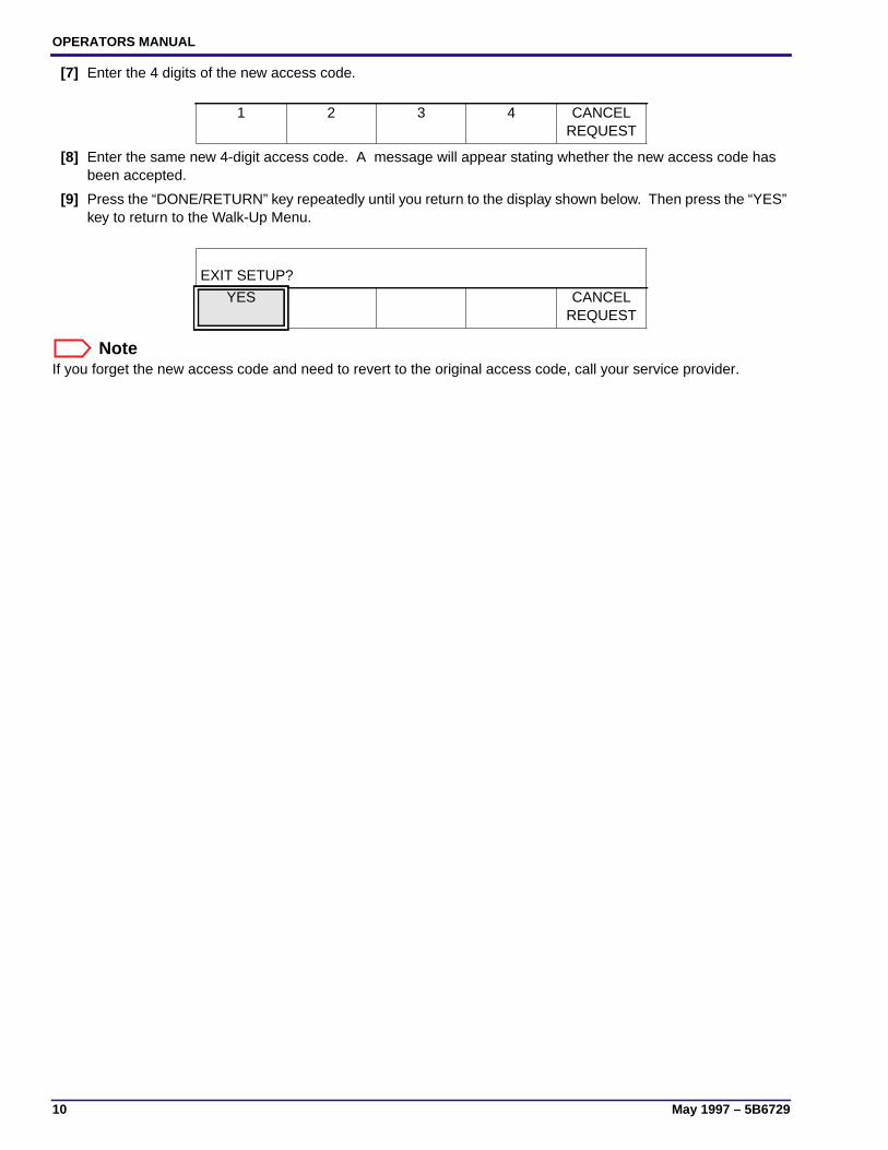
[7] Enter the 4 digits of the new access code.
[8] Enter the same new 4-digit access code. A message will appear stating whether the new access code hasbeen accepted.
[9] Press the “DONE/RETURN” key repeatedly until you return to the display shown below. Then press the “YES”key to return to the Walk-Up Menu.
NoteIf you forget the new access code and need to revert to the original access code, call your service provider.
1 2 3 4 CANCELREQUEST
EXIT SETUP?
YES CANCELREQUEST
5B6729 – May 1997 11
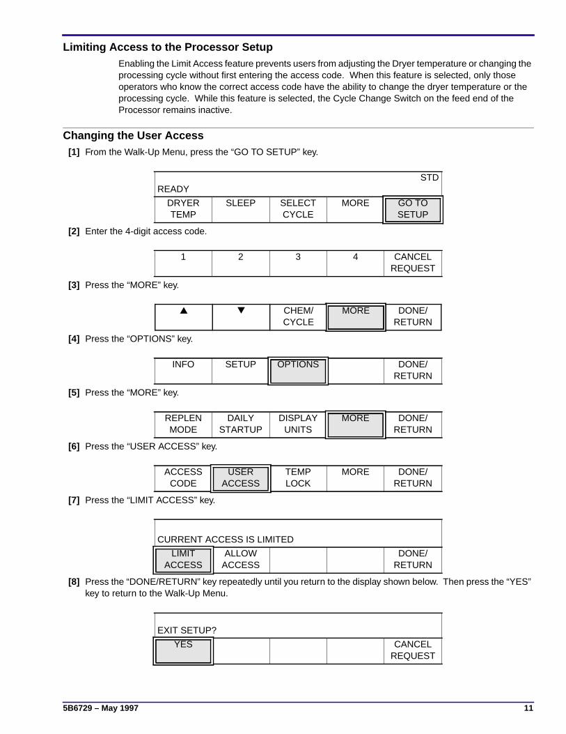
Limiting Access to the Processor SetupEnabling the Limit Access feature prevents users from adjusting the Dryer temperature or changing theprocessing cycle without first entering the access code. When this feature is selected, only thoseoperators who know the correct access code have the ability to change the dryer temperature or theprocessing cycle. While this feature is selected, the Cycle Change Switch on the feed end of theProcessor remains inactive.
Changing the User Access[1] From the Walk-Up Menu, press the “GO TO SETUP” key.
[2] Enter the 4-digit access code.
[3] Press the “MORE” key.
[4] Press the “OPTIONS” key.
[5] Press the “MORE” key.
[6] Press the “USER ACCESS” key.
[7] Press the “LIMIT ACCESS” key.
[8] Press the “DONE/RETURN” key repeatedly until you return to the display shown below. Then press the “YES”key to return to the Walk-Up Menu.
READYSTD
DRYERTEMP
SLEEP SELECTCYCLE
MORE GO TOSETUP
1 2 3 4 CANCELREQUEST
▲ ▼ CHEM/CYCLE
MORE DONE/RETURN
INFO SETUP OPTIONS DONE/RETURN
REPLENMODE
DAILYSTARTUP
DISPLAYUNITS
MORE DONE/RETURN
ACCESSCODE
USERACCESS
TEMPLOCK
MORE DONE/RETURN
CURRENT ACCESS IS LIMITED
LIMITACCESS
ALLOWACCESS
DONE/RETURN
EXIT SETUP?
YES CANCELREQUEST

OPERATORS MANUAL
12 May 1997 – 5B6729
Operating Characteristics• All menus appearing before the point you are required to enter the access code give you only
20 seconds to press a key. If you do not press a key within that time, the Walk-Up Menu willappear.
• All menus appearing after the point you are required to enter the access code give you 2 minutesto press a key. If you do not press a key within that time, the Walk-Up Menu will appear.
• When you first turn on the Processor, the wash water and Drive Motor run for 4 minutes and thenturn off. The Replenishment Pumps also turn on briefly.
• If either the developer or fixer solution evaporated while the Processor was off, the developer andfixer Tanks will be automatically replenished to their overflow levels when you turn on theProcessor.
• When film is fed, the Drive Motor, the Dryer Blower, and water turn on immediately.
• The Drive Motor will not operate if the Top Cover of the Processor is removed.
• The Display Panel remains illuminated unless the Processor is placed in Sleep Mode. However, ifyour Processor is installed in a darkroom and you want the Display Panel to dim when the room isdark to avoid fogging films, your service provider can enable the roomlight Sensor. Enabling theSensor will cause the Display Panel to dim automatically when the room lights are turned off.
• All errors and warnings cause the alarm on the Processor to sound twice when a film is fed into theFilm Detector.
5B6729 – May 1997 13
Operating Instructions
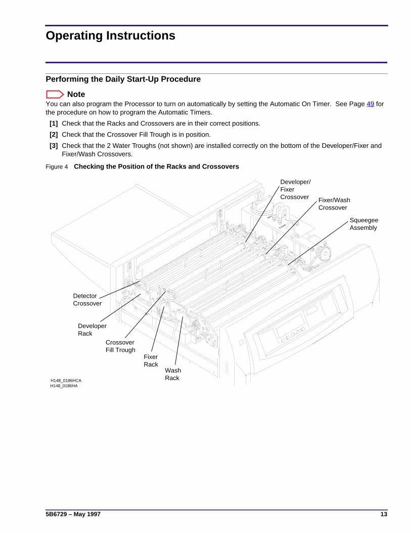
Performing the Daily Start-Up Procedure
NoteYou can also program the Processor to turn on automatically by setting the Automatic On Timer. See Page 49 forthe procedure on how to program the Automatic Timers.
[1] Check that the Racks and Crossovers are in their correct positions.
[2] Check that the Crossover Fill Trough is in position.
[3] Check that the 2 Water Troughs (not shown) are installed correctly on the bottom of the Developer/Fixer andFixer/Wash Crossovers.
Figure 4 Checking the Position of the Racks and Crossovers
FIXER
DEV
H148_0186HAH148_0186HCA
AssemblySqueegee
RackWash
CrossoverFixer/Wash
RackFixer
CrossoverFixerDeveloper/
RackDeveloper
CrossoverDetector
Fill TroughCrossover

OPERATORS MANUAL
14 May 1997 – 5B6729
Figure 5 Installing the Evaporation Covers
[4] Check that developer and fixer solutions are near the overflow levels of each Tank.
[5] Install the Evaporation Covers on the Crossovers and the Top Cover on the Processor.
[6] Turn on the water supply.
ImportantThe incoming water temperature should be between 4 and 29°C (40 and 85°F).
[7] Remove any film from the Feed Tray.
[8] Move the wall power switch to the “ON” position.
[9] Move the main Circuit Breaker CB1 to the “ON” position.
[10] For optimum processing quality, allow approximately 20 minutes for the processing solutions to reach thecorrect operating temperature before you feed film. The Ready Indicator will illuminate once the solutions havereached the correct temperature.
Performing the Shutdown Procedure
NoteYou can also program the Processor to shut down automatically by setting the Automatic Off Timer. See Page 49for the procedure on how to set the Automatic Timers.
[1] Move the main Circuit Breaker CB1 to the “OFF” position.
[2] Move the wall power switch to the “OFF” position.
[3] Turn off the water supply.
H148_0036BAH148_0036BCB
Evaporation Covers
5B6729 – May 1997 15
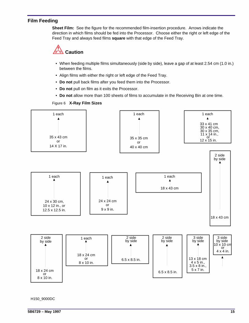
Film FeedingSheet Film: See the figure for the recommended film-insertion procedure. Arrows indicate thedirection in which films should be fed into the Processor. Choose either the right or left edge of theFeed Tray and always feed films square with that edge of the Feed Tray.
Caution
• When feeding multiple films simultaneously (side by side), leave a gap of at least 2.54 cm (1.0 in.)between the films.
• Align films with either the right or left edge of the Feed Tray.
• Do not pull back films after you feed them into the Processor.
• Do not pull on film as it exits the Processor.
• Do not allow more than 100 sheets of films to accumulate in the Receiving Bin at one time.
Figure 6 X-Ray Film Sizes
H150_9000DC
2 sideby side
3 sideby side
3 sideby side
2 sideby side
2 sideby side
by side
13 x 18 cm
12 x 15 in.or
11 x 14 in.,
4 x 4 in.or
10 x 10 cm
5 x 7 in.3.5 x 8 in.,4 x 5 in.,
6.5 x 8.5 in.
6.5 x 8.5 in.8 x 10 in.
or18 x 24 cm
1 each
8 x 10 in.or
18 x 24 cm
18 x 43 cm
2 side
18 x 43 cm
1 each
9 x 9 in.or
24 x 24 cm
1 each
12.5 x 12.5 in.10 x 12 in., or24 x 30 cm,
1 each
30 x 35 cm,30 x 40 cm,33 x 41 cm
1 each
40 x 40 cmor
35 x 35 cm
1 each
14 X 17 in.or
35 x 43 cm
1 each
OPERATORS MANUAL
16 May 1997 – 5B6729
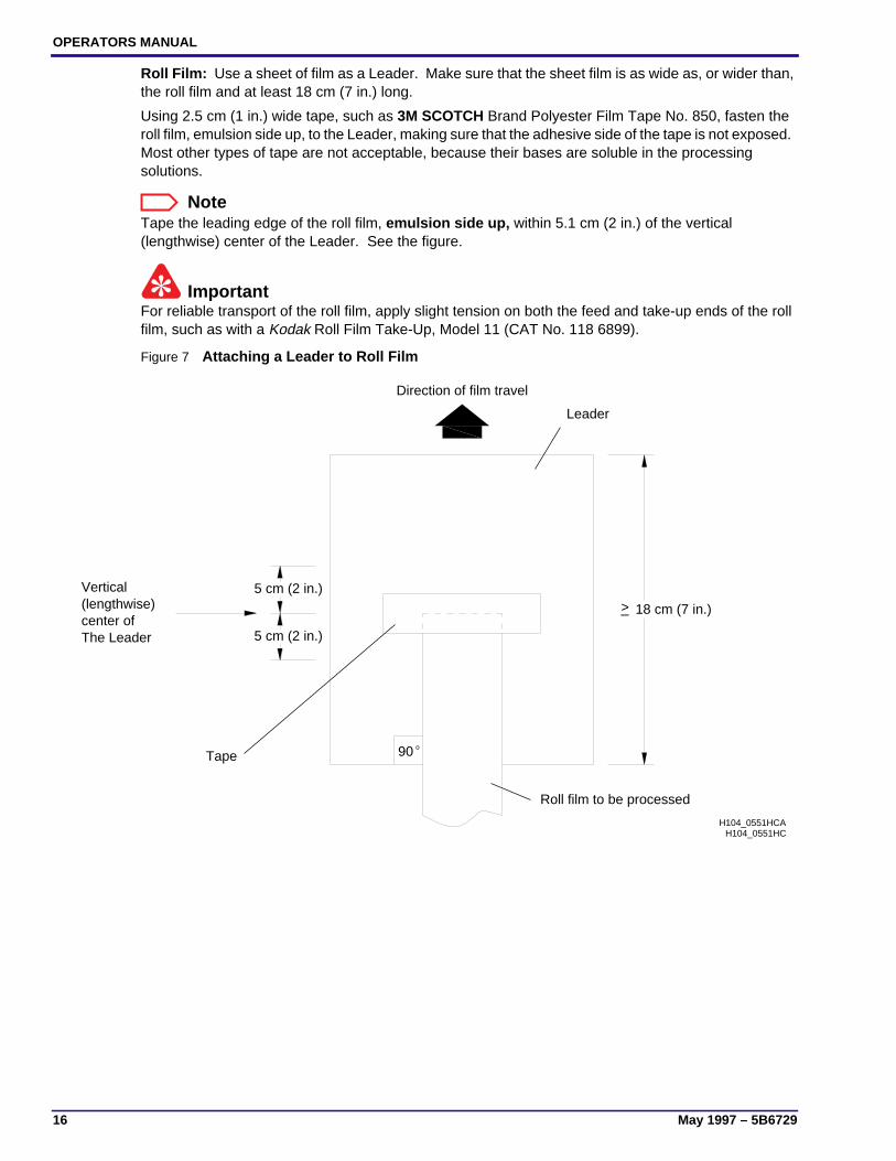
Roll Film: Use a sheet of film as a Leader. Make sure that the sheet film is as wide as, or wider than,the roll film and at least 18 cm (7 in.) long.
Using 2.5 cm (1 in.) wide tape, such as 3M SCOTCH Brand Polyester Film Tape No. 850, fasten theroll film, emulsion side up, to the Leader, making sure that the adhesive side of the tape is not exposed.Most other types of tape are not acceptable, because their bases are soluble in the processingsolutions.
NoteTape the leading edge of the roll film, emulsion side up, within 5.1 cm (2 in.) of the vertical(lengthwise) center of the Leader. See the figure.
ImportantFor reliable transport of the roll film, apply slight tension on both the feed and take-up ends of the rollfilm, such as with a Kodak Roll Film Take-Up, Model 11 (CAT No. 118 6899).
Figure 7 Attaching a Leader to Roll Film
H104_0551HC
The Leadercenter of (lengthwise)Vertical
Direction of film travel
o90
5 cm (2 in.)
5 cm (2 in.)
>_ 18 cm (7 in.)
H104_0551HCA
Roll film to be processed
Leader
Tape
Summary of Default Settings
5B6729 – May 1997 17
Default Setpoints and Configurations
Section 1: Summary of Default Settings
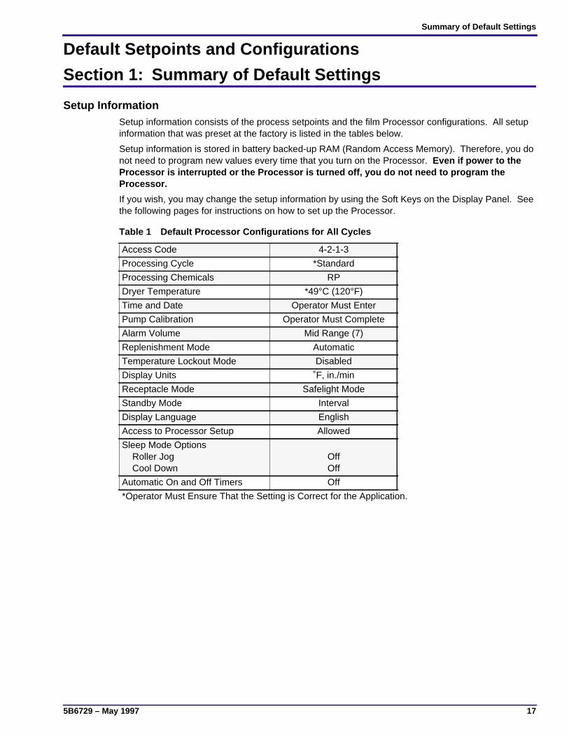
Setup InformationSetup information consists of the process setpoints and the film Processor configurations. All setupinformation that was preset at the factory is listed in the tables below.
Setup information is stored in battery backed-up RAM (Random Access Memory). Therefore, you donot need to program new values every time that you turn on the Processor. Even if power to theProcessor is interrupted or the Processor is turned off, you do not need to program theProcessor.
If you wish, you may change the setup information by using the Soft Keys on the Display Panel. Seethe following pages for instructions on how to set up the Processor.
Table 1 Default Processor Configurations for All Cycles
Access Code 4-2-1-3
Processing Cycle *Standard
Processing Chemicals RP
Dryer Temperature *49°C (120°F)
Time and Date Operator Must Enter
Pump Calibration Operator Must Complete
Alarm Volume Mid Range (7)
Replenishment Mode Automatic
Temperature Lockout Mode Disabled
Display Units ˚F, in./min
Receptacle Mode Safelight Mode
Standby Mode Interval
Display Language English
Access to Processor Setup Allowed
Sleep Mode Options Roller Jog Cool Down
OffOff
Automatic On and Off Timers Off
*Operator Must Ensure That the Setting is Correct for the Application.

OPERATORS MANUAL
18 May 1997 – 5B6729
Table 2 Default Processor Setpoints for Each Cycle
Item
Chemicals and Cycle
RA Chemicals RP Chemicals
K/RA RAPID STANDARD EXTENDED
DeveloperTemperature
36.7°C(98°F)
38.3°C(101°F)
35.0°C(95°F)
35.0°C(95°F)
Fixer Temperature(minimum)
35.0°C(95°F)
35.0°C(95°F)
35.0°C(95°F)
35.0°C(95°F)
DeveloperReplenishmentVolume(35 x 43 cm sheet)AutomaticFlooded
60 mL65 mL
60 mL65 mL
60 mL65 mL
60 mL65 mL
FixerReplenishmentVolume(35 x 43 cm sheet)AutomaticFlooded
85 mL65 mL
85 mL65 mL
85 mL65 mL
85 mL65 mL
Transport Speed 342.9 cm/min(135 in./min)
251.5 cm/min(99 in./min)
167.6 cm/min(66 in./min)
86.4 cm/min(34 in./min)
Dryer Temperature 48.9°C(120°F)
48.9°C(120°F)
48.9°C(120°F)
48.9°C(120°F)
Basic Setup Options
5B6729 – May 1997 19
Section 2: Basic Setup Options
Selecting a Film Processing Cycle
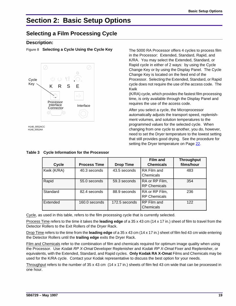
Description:Figure 8 Selecting a Cycle Using the Cycle Key The 5000 RA Processor offers 4 cycles to process film
in the Processor: Extended, Standard, Rapid, andK/RA. You may select the Extended, Standard, orRapid cycle in either of 2 ways: by using the CycleChange Key or by using the Display Panel. The CycleChange Key is located on the feed end of theProcessor. Selecting the Extended, Standard, or Rapidcycle does not require the use of the access code. TheKwik(K/RA) cycle, which provides the fastest film processingtime, is only available through the Display Panel andrequires the use of the access code.
After you select a cycle, the Microprocessorautomatically adjusts the transport speed, replenish-ment volumes, and solution temperatures to theprogrammed values for the selected cycle. Whenchanging from one cycle to another, you do, however,need to set the Dryer temperature to the lowest settingthat still provides good drying. See the procedure forsetting the Dryer temperature on Page 22.
Table 3 Cycle Information for the Processor
Cycle, as used in this table, refers to the film processing cycle that is currently selected.
Process Time refers to the time it takes the leading edge of a 35 x 43 cm (14 x 17 in.) sheet of film to travel from theDetector Rollers to the Exit Rollers of the Dryer Rack.
Drop Time refers to the time from the leading edge of a 35 x 43 cm (14 x 17 in.) sheet of film fed 43 cm wide enteringthe Detector Rollers until the trailing edge exits the Dryer Rack.
Film and Chemicals refer to the combination of film and chemicals required for optimum image quality when usingthe Processor. Use Kodak RP X-Omat Developer Replenisher and Kodak RP X-Omat Fixer and Replenisher, orequivalents, with the Extended, Standard, and Rapid cycles. Only Kodak RA X-Omat Films and Chemicals may beused for the K/RA cycle. Contact your Kodak representative to discuss the best option for your needs.
Throughput refers to the number of 35 x 43 cm (14 x 17 in.) sheets of film fed 43 cm wide that can be processed inone hour.
K R S E
H148_0052AA
ProcessorInterfaceConnector
Interface
H148_0052ACC
KeyCycle
Cycle Process Time Drop TimeFilm and
ChemicalsThroughputfilms/hour
Kwik (K/RA) 40.3 seconds 43.5 seconds RA Film andChemicals
483
Rapid 55.0 seconds 59.3 seconds RA or RP Film,RP Chemicals
354
Standard 82.4 seconds 88.9 seconds RA or RP Film,RP Chemicals
236
Extended 160.0 seconds 172.5 seconds RP Film andChemicals
122
OPERATORS MANUAL
20 May 1997 – 5B6729
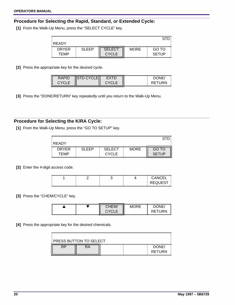
Procedure for Selecting the Rapid, Standard, or Extended Cycle:[1] From the Walk-Up Menu, press the “SELECT CYCLE” key.
[2] Press the appropriate key for the desired cycle.
[3] Press the “DONE/RETURN” key repeatedly until you return to the Walk-Up Menu.
Procedure for Selecting the K/RA Cycle:[1] From the Walk-Up Menu, press the “GO TO SETUP” key.
[2] Enter the 4-digit access code.
[3] Press the “CHEM/CYCLE” key.
[4] Press the appropriate key for the desired chemicals.
READYSTD
DRYERTEMP
SLEEP SELECTCYCLE
MORE GO TOSETUP
RAPIDCYCLE
STD CYCLE EXTDCYCLE
DONE/RETURN
READYSTD
DRYERTEMP
SLEEP SELECTCYCLE
MORE GO TOSETUP
1 2 3 4 CANCELREQUEST
▲ ▼ CHEM/CYCLE
MORE DONE/RETURN
PRESS BUTTON TO SELECT
RP RA DONE/RETURN

Basic Setup Options
5B6729 – May 1997 21
[5] One of the following displays will appear:
(a) If you selected RP chemicals, press the appropriate key for the desired cycle.
(b) If you selected RA chemicals, press the “K/RA CYCLE” key.
[6] Press the “DONE/RETURN” key repeatedly until you return to the display shown below. Then press the “YES”key to return to the Walk-Up Menu.
PRESS BUTTON TO SELECTSTD
RAPIDCYCLE
STD CYCLE EXTDCYCLE
DONE/RETURN
PRESS BUTTON TO SELECTK/RA
K/RACYCLE
DONE/RETURN
EXIT SETUP?
YES CANCELREQUEST
OPERATORS MANUAL
22 May 1997 – 5B6729
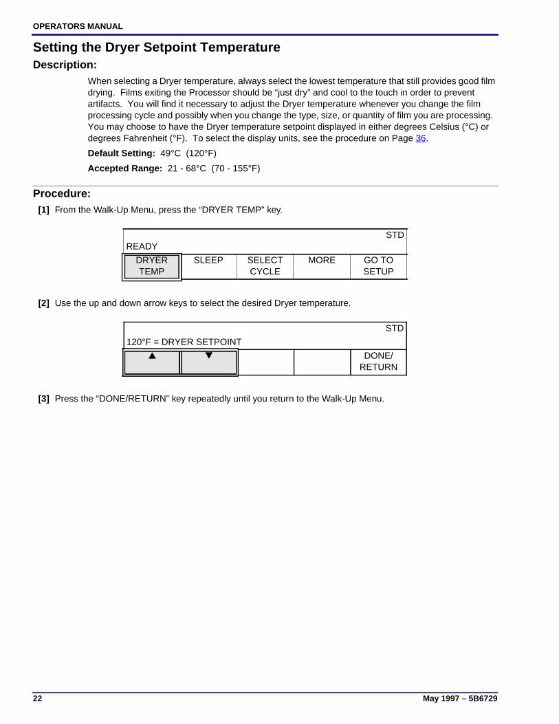
Setting the Dryer Setpoint TemperatureDescription:
When selecting a Dryer temperature, always select the lowest temperature that still provides good filmdrying. Films exiting the Processor should be “just dry” and cool to the touch in order to preventartifacts. You will find it necessary to adjust the Dryer temperature whenever you change the filmprocessing cycle and possibly when you change the type, size, or quantity of film you are processing.You may choose to have the Dryer temperature setpoint displayed in either degrees Celsius (°C) ordegrees Fahrenheit (°F). To select the display units, see the procedure on Page 36.
Default Setting: 49°C (120°F)
Accepted Range: 21 - 68°C (70 - 155°F)
Procedure:[1] From the Walk-Up Menu, press the “DRYER TEMP” key.
[2] Use the up and down arrow keys to select the desired Dryer temperature.
[3] Press the “DONE/RETURN” key repeatedly until you return to the Walk-Up Menu.
READYSTD
DRYERTEMP
SLEEP SELECTCYCLE
MORE GO TOSETUP
STD
120°F = DRYER SETPOINT
▲ ▼ DONE/RETURN

Basic Setup Options
5B6729 – May 1997 23
Setting the Time and DateDescription:
By setting the Clock in the Processor, you can take advantage of several of the features that theProcessor offers:
• Auto Start-Up and Shutdown
• Time and Date Stamping of Error Messages
When setting the time and date, you may choose from several different formats:
Time Formats:
• 12 Hour
• 24 Hour
Date Formats (where M=Month, D=Day, and Y=Year):
• M-D-Y
• D-M-Y
• Y-M-D
Procedure:[1] From the Walk-Up Menu, press the “GO TO SETUP” key.
[2] Enter the 4-digit access code.
[3] Press the “MORE” key.
[4] Press the “SETUP” key.
[5] Press the “CLOCK” key.
[6] Press the “TIME FORMAT” key.
READYSTD
DRYERTEMP
SLEEP SELECTCYCLE
MORE GO TOSETUP
1 2 3 4 CANCELREQUEST
▲ ▼ CHEM/CYCLE
MORE DONE/RETURN
INFO SETUP OPTIONS DONE/RETURN
PROCESS CLOCK AUTOSTARTUP
PUMPCALIB
DONE/RETURN
SETTIME
SETDATE
TIMEFORMAT
DATEFORMAT
DONE/RETURN

OPERATORS MANUAL
24 May 1997 – 5B6729
[7] Select the “FORMAT” key of your choice.
[8] Press the “DONE/RETURN” key once to return to the format options.
[9] Press the “DATE FORMAT” key.
[10] Select the “FORMAT” key of your choice.
[11] Press the “DONE/RETURN” key once to return to the set time and set date options.
[12] Press the “SET TIME” key.
[13] Use the up and down arrow keys to set the time in hours and minutes.
[14] Press the “DONE/RETURN” key once to return to the set date option.
[15] Press the “SET DATE” key.
[16] Press the “SET DATE” key.
[17] Use the up and down arrow keys to set the date.
[18] Press the “DONE/RETURN” key once to return to the set year option.
12 HOUR = TIME DISPLAY FORMAT
12 HOURFORMAT
24 HOURFORMAT
DONE/RETURN
SETTIME
SETDATE
TIMEFORMAT
DATEFORMAT
DONE/RETURN
M-D-Y = DATE DISPLAY FORMAT
M-D-YFORMAT
D-M-YFORMAT
Y-M-DFORMAT
DONE/RETURN
SETTIME
SETDATE
TIMEFORMAT
DATEFORMAT
DONE/RETURN
12:30 AM = CURRENT TIME
▲
HOUR▼
HOUR▲
MINUTE▼
MINUTEDONE/
RETURN
SETTIME
SETDATE
TIMEFORMAT
DATEFORMAT
DONE/RETURN
SETDATE
SETYEAR
DONE/RETURN
10-31 = CURRENT DATE
▲
MONTH▼
MONTH▲
DAY▼
DAYDONE/
RETURN
Basic Setup Options
5B6729 – May 1997 25
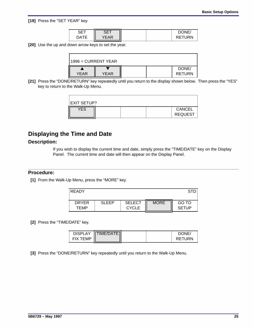
[19] Press the “SET YEAR” key.
[20] Use the up and down arrow keys to set the year.
[21] Press the “DONE/RETURN” key repeatedly until you return to the display shown below. Then press the “YES”key to return to the Walk-Up Menu.
Displaying the Time and DateDescription:
If you wish to display the current time and date, simply press the “TIME/DATE” key on the DisplayPanel. The current time and date will then appear on the Display Panel.
Procedure:[1] From the Walk-Up Menu, press the “MORE” key.
[2] Press the “TIME/DATE” key.
[3] Press the “DONE/RETURN” key repeatedly until you return to the Walk-Up Menu.
SETDATE
SETYEAR
DONE/RETURN
1996 = CURRENT YEAR
▲
YEAR▼
YEARDONE/
RETURN
EXIT SETUP?
YES CANCELREQUEST
READY STD
DRYERTEMP
SLEEP SELECTCYCLE
MORE GO TOSETUP
DISPLAYFIX TEMP
TIME/DATE DONE/RETURN
OPERATORS MANUAL
26 May 1997 – 5B6729
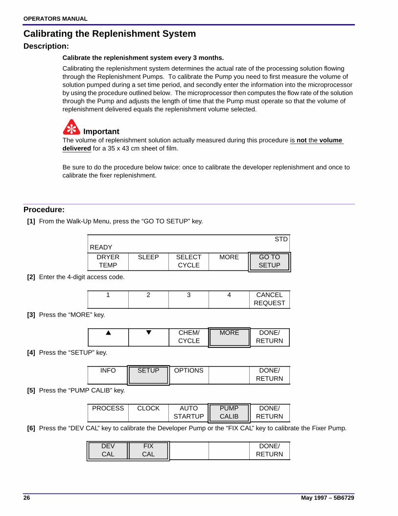
Calibrating the Replenishment SystemDescription:
Calibrate the replenishment system every 3 months.
Calibrating the replenishment system determines the actual rate of the processing solution flowingthrough the Replenishment Pumps. To calibrate the Pump you need to first measure the volume ofsolution pumped during a set time period, and secondly enter the information into the microprocessorby using the procedure outlined below. The microprocessor then computes the flow rate of the solutionthrough the Pump and adjusts the length of time that the Pump must operate so that the volume ofreplenishment delivered equals the replenishment volume selected.
ImportantThe volume of replenishment solution actually measured during this procedure is not the volumedelivered for a 35 x 43 cm sheet of film.
Be sure to do the procedure below twice: once to calibrate the developer replenishment and once tocalibrate the fixer replenishment.
Procedure:[1] From the Walk-Up Menu, press the “GO TO SETUP” key.
[2] Enter the 4-digit access code.
[3] Press the “MORE” key.
[4] Press the “SETUP” key.
[5] Press the “PUMP CALIB” key.
[6] Press the “DEV CAL” key to calibrate the Developer Pump or the “FIX CAL” key to calibrate the Fixer Pump.
READYSTD
DRYERTEMP
SLEEP SELECTCYCLE
MORE GO TOSETUP
1 2 3 4 CANCELREQUEST
▲ ▼ CHEM/CYCLE
MORE DONE/RETURN
INFO SETUP OPTIONS DONE/RETURN
PROCESS CLOCK AUTOSTARTUP
PUMPCALIB
DONE/RETURN
DEVCAL
FIXCAL
DONE/RETURN
Basic Setup Options
5B6729 – May 1997 27
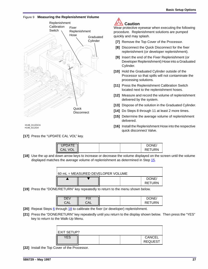
Figure 9 Measuring the Replenishment Volume
CautionWear protective eyewear when executing the followingprocedure. Replenishment solutions are pumpedquickly and may splash.
[7] Remove the Top Cover of the Processor.
[8] Disconnect the Quick Disconnect for the fixerreplenishment (or developer replenishment).
[9] Insert the end of the Fixer Replenishment (orDeveloper Replenishment) Hose into a GraduatedCylinder.
[10] Hold the Graduated Cylinder outside of theProcessor so that spills will not contaminate theprocessing solutions.
[11] Press the Replenishment Calibration Switchlocated next to the replenishment hoses.
[12] Measure and record the volume of replenishmentdelivered by the system.
[13] Dispose of the solution in the Graduated Cylinder.
[14] Do Steps 8 through 11 at least 2 more times.
[15] Determine the average volume of replenishmentdelivered.
[16] Install the Replenishment Hose into the respectivequick disconnect Valve.
[17] Press the “UPDATE CAL VOL” key.
[18] Use the up and down arrow keys to increase or decrease the volume displayed on the screen until the volumedisplayed matches the average volume of replenishment as determined in Step 15.
[19] Press the “DONE/RETURN” key repeatedly to return to the menu shown below.
[20] Repeat Steps 6 through 18 to calibrate the fixer (or developer) replenishment.
[21] Press the “DONE/RETURN” key repeatedly until you return to the display shown below. Then press the “YES”key to return to the Walk-Up Menu.
[22] Install the Top Cover of the Processor.
FIXER
DEV
H148_0112GA
FixerReplenishmentHose
GraduatedCylinder
H148_0112GCA
ReplenishmentCalibrationSwitch
QuickDisconnect
UPDATECAL VOL
DONE/RETURN
60 mL = MEASURED DEVELOPER VOLUME
▲ ▼ DONE/RETURN
DEVCAL
FIXCAL
DONE/RETURN
EXIT SETUP?
YES CANCELREQUEST

OPERATORS MANUAL
28 May 1997 – 5B6729
Selecting a Replenishment ModeDescription:
Automatic Replenishment Mode
Select this mode when you want the Processor to automatically adjust the replenishment volumes fordeveloper and fixer according to film usage. See the procedure “Setting the Developer and FixerReplenishment Volumes” beginning on Page 44.
Flooded Replenishment Mode
Select this mode if your site has low film usage of less than 25 sheets of 35 x 43 cm (14 x 17 in.) filmor equivalent area per 8-hour day. Check with your Kodak representative to see whether theFlooded Replenishment Mode is right for the film usage of the Processor. Replenishment will be addedautomatically —
• every 5 minutes
• when the equivalent film area of 35 x 43 cm (14 x 17 in.) has been processed.
Tank Fill Mode
Select this mode to fill empty Processor Tanks automatically. A warning error stating that the “TanksCurrently Being Filled” occurs as the Tanks are filling. After the Tanks are filled, the error is clearedand the Processor will begin normal operation.
Disable Replenishment
Select this feature to disable the Replenishment Pumps before doing any of the cleaning procedures.When the Pumps are disabled, a warning error stating that the “Replenishment Pumps Disabled”occurs. To clear the error, simply select either Automatic or Flooded Replenishment.
Default Setting: Automatic
Procedure:[1] Press the “GO TO SETUP” key.
NoteThe “SELECT CYCLE” key does not appear if you have selected the K/RA cycle.
[2] Enter the 4-digit access code.
[3] Press the “MORE” key.
[4] Press the “OPTIONS” key.
READYSTD
DRYERTEMP
SLEEP SELECTCYCLE
MORE GO TOSETUP
1 2 3 4 CANCELREQUEST
▲ ▼ CHEM/CYCLE
MORE DONE/RETURN
INFO SETUP OPTIONS DONE/RETURN

Basic Setup Options
5B6729 – May 1997 29
[5] Press the “REPLEN MODE” key.
[6] Select one of the 4 replenishment modes:
• Automatic Replenishment
• Flooded Replenishment
• Tank Fill
• Disable Replenishment
[7] Press the “DONE/RETURN” key repeatedly until you return to the display shown below. Then press the “YES”key to return to the Walk-Up Menu.
REPLENMODE
DAILYSTARTUP
DISPLAYUNITS
MORE DONE/RETURN
REPLENISHMENT MODE IS AUTO
AUTO FLOODED TANK FILL DISABLEREPLEN
DONE/RETURN
EXIT SETUP?
YES CANCELREQUEST

OPERATORS MANUAL
30 May 1997 – 5B6729
Selecting the Standby ModeDescription:
The Processor will enter the Standby mode after the trailing edge of the last sheet of film exits the Dryer.There are 2 modes within the Standby mode — the Interval mode and the Continuous mode. With theProcessor in the Interval mode, the transport system and wash water turn on periodically to keep theRollers wet. When the Processor is in the Continuous mode, the transport system will operatecontinuously at a reduced speed to keep the Rollers wet. In either mode, the following actions takeplace:
• the Dryer Blower and Heater turn on as needed to maintain the temperature of the Dryer.
• the wash water turns on every 8 minutes and remains on for 90 seconds to clean the Rollers.
• the solution Heaters remain on as needed to maintain the setpoint temperature of the solutions.
Default Setting: Interval
Procedure:[1] From the Walk-Up Menu, press the “GO TO SETUP” key.
[2] Enter the 4-digit access code.
[3] Press the “MORE” key.
[4] Press the “OPTIONS” key.
[5] Press the “MORE” key.
[6] Press the “MORE” key.
[7] Press the “STANDBY MODE” key.
READYSTD
DRYERTEMP
SLEEP SELECTCYCLE
MORE GO TOSETUP
1 2 3 4 CANCELREQUEST
▲ ▼ CHEM/CYCLE
MORE DONE/RETURN
INFO SETUP OPTIONS DONE/RETURN
REPLENMODE
DAILYSTARTUP
DISPLAYUNITS
MORE DONE/RETURN
ACCESSCODE
USERACCESS
TEMPLOCK
MORE DONE/RETURN
STANDBYMODE
ROLLERJOG
COOLDOWN
MORE DONE/RETURN
Basic Setup Options
5B6729 – May 1997 31
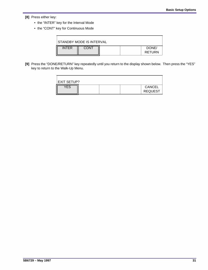
[8] Press either key:
• the “INTER” key for the Interval Mode
• the “CONT” key for Continuous Mode
[9] Press the “DONE/RETURN” key repeatedly until you return to the display shown below. Then press the “YES”key to return to the Walk-Up Menu.
STANDBY MODE IS INTERVAL
INTER CONT DONE/RETURN
EXIT SETUP?
YES CANCELREQUEST

OPERATORS MANUAL
32 May 1997 – 5B6729
Setting the Volume of the AlarmDescription:
The Processor includes an audible alarm that signals the user when to feed films in order to ensure theproper spacing of films. The alarm also signals the occurrence of an error or warning. The volume ofthe alarm is adjustable among 15 different levels. As you increase or decrease the volume of the alarm,the alarm sounds continuously so that you can hear the current volume level you selected. The alarmcontinues to sound until you press the “DONE/RETURN” key or until the screen time-out expires.
Default Setting: Mid Range (7)
Accepted Range: 0 - 15
Procedure:[1] From the Walk-Up Menu, press the “GO TO SETUP” key.
[2] Enter the 4-digit access code.
[3] Press the “MORE” key.
[4] Press the “OPTIONS” key.
[5] Press the “MORE” key.
[6] Press the “MORE” key.
[7] Press the “MORE” key.
[8] Press the “ALARM VOLUME” key.
READYSTD
DRYERTEMP
SLEEP SELECTCYCLE
MORE GO TOSETUP
1 2 3 4 CANCELREQUEST
▲ ▼ CHEM/CYCLE
MORE DONE/RETURN
INFO SETUP OPTIONS DONE/RETURN
REPLENMODE
DAILYSTARTUP
DISPLAYUNITS
MORE DONE/RETURN
ACCESSCODE
USERACCESS
TEMPLOCK
MORE DONE/RETURN
STANDBYMODE
ROLLERJOG
COOLDOWN
MORE DONE/RETURN
RECPTMODE
ALARMVOLUME
MORE DONE/RETURN
Basic Setup Options
5B6729 – May 1997 33
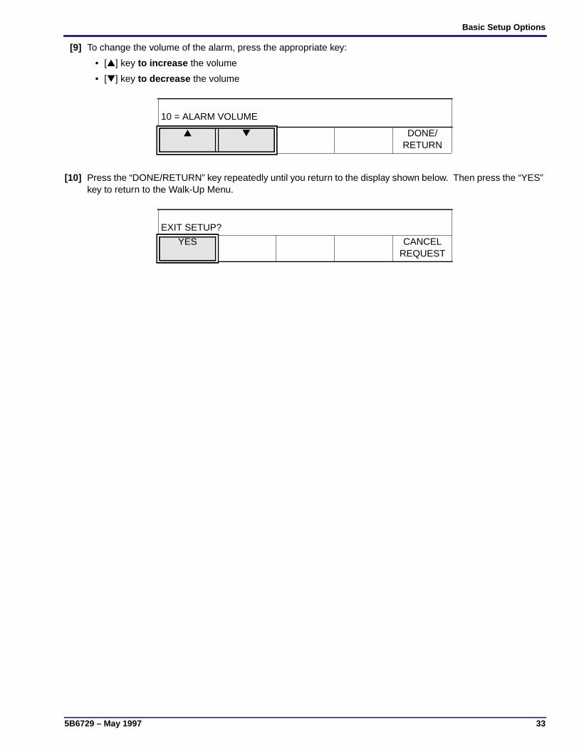
[9] To change the volume of the alarm, press the appropriate key:
• [▲] key to increase the volume
• [▼] key to decrease the volume
[10] Press the “DONE/RETURN” key repeatedly until you return to the display shown below. Then press the “YES”key to return to the Walk-Up Menu.
10 = ALARM VOLUME
▲ ▼ DONE/RETURN
EXIT SETUP?
YES CANCELREQUEST
OPERATORS MANUAL
34 May 1997 – 5B6729
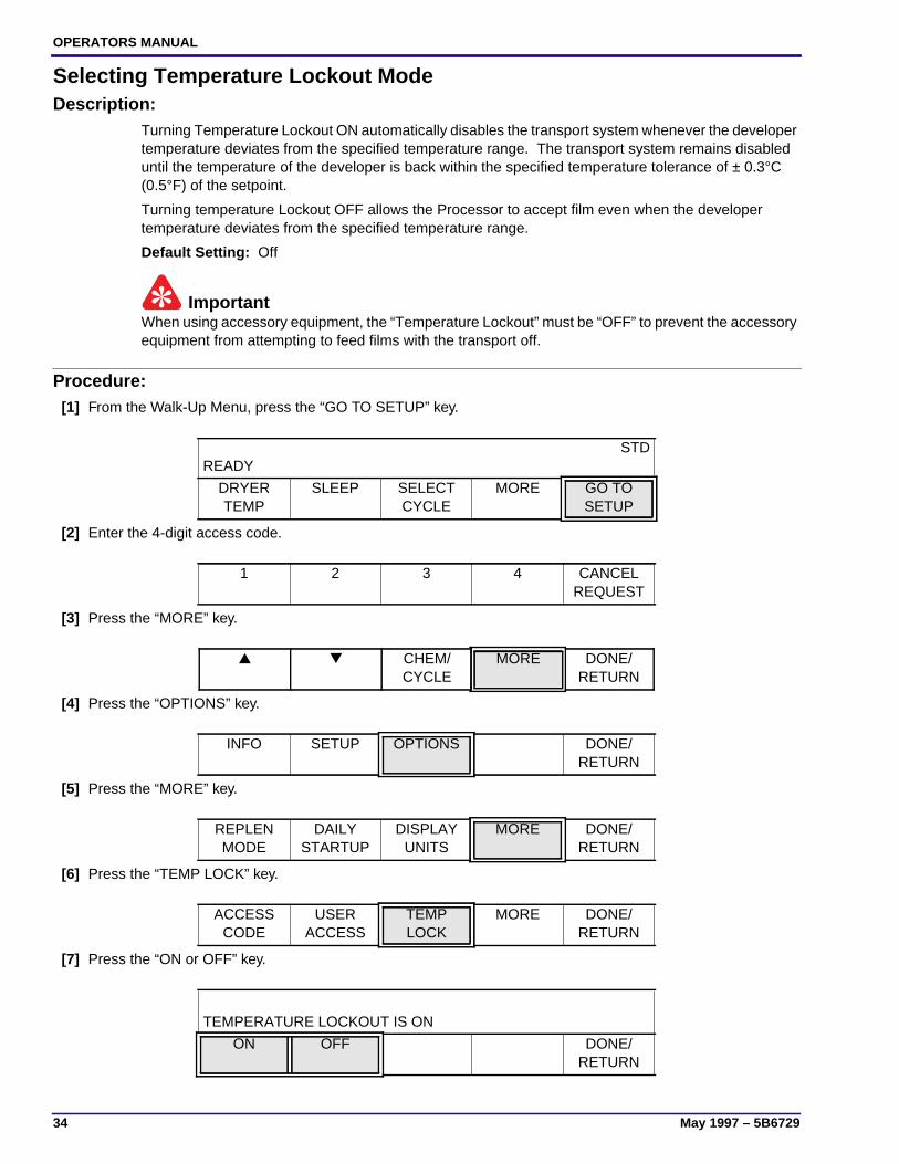
Selecting Temperature Lockout ModeDescription:
Turning Temperature Lockout ON automatically disables the transport system whenever the developertemperature deviates from the specified temperature range. The transport system remains disableduntil the temperature of the developer is back within the specified temperature tolerance of ± 0.3°C(0.5°F) of the setpoint.
Turning temperature Lockout OFF allows the Processor to accept film even when the developertemperature deviates from the specified temperature range.
Default Setting: Off
ImportantWhen using accessory equipment, the “Temperature Lockout” must be “OFF” to prevent the accessoryequipment from attempting to feed films with the transport off.
Procedure:[1] From the Walk-Up Menu, press the “GO TO SETUP” key.
[2] Enter the 4-digit access code.
[3] Press the “MORE” key.
[4] Press the “OPTIONS” key.
[5] Press the “MORE” key.
[6] Press the “TEMP LOCK” key.
[7] Press the “ON or OFF” key.
READYSTD
DRYERTEMP
SLEEP SELECTCYCLE
MORE GO TOSETUP
1 2 3 4 CANCELREQUEST
▲ ▼ CHEM/CYCLE
MORE DONE/RETURN
INFO SETUP OPTIONS DONE/RETURN
REPLENMODE
DAILYSTARTUP
DISPLAYUNITS
MORE DONE/RETURN
ACCESSCODE
USERACCESS
TEMPLOCK
MORE DONE/RETURN
TEMPERATURE LOCKOUT IS ON
ON OFF DONE/RETURN

Basic Setup Options
5B6729 – May 1997 35
[8] Press the “DONE/RETURN” key repeatedly until you return to the display shown below. Then press the “YES”key to return to the Walk-Up Menu.
EXIT SETUP?
YES CANCELREQUEST

OPERATORS MANUAL
36 May 1997 – 5B6729
Selecting Display UnitsDescription:
The software of the Processor allows you to choose either degrees Fahrenheit (°F) or degrees Celsius(°C) for temperature units, and either English or Metric units for measuring length.
Default Setting: °F and in./min
Procedure:[1] From the Walk-Up Menu, press the “GO TO SETUP” key.
[2] Enter the 4-digit access code.
[3] Press the “MORE” key.
[4] Press the “OPTIONS” key.
[5] Press the “DISPLAY UNITS” key.
[6] Press either key:
• “ENGLISH” for °F and in./min or
• “METRIC” for °C and cm/min
[7] Press the “DONE/RETURN” key repeatedly until you return to the display shown below. Then press the “YES”key to return to the Walk-Up Menu.
READYSTD
DRYERTEMP
SLEEP SELECTCYCLE
MORE GO TOSETUP
1 2 3 4 CANCELREQUEST
▲ ▼ CHEM/CYCLE
MORE DONE/RETURN
INFO SETUP OPTIONS DONE/RETURN
REPLENMODE
DAILYSETUP
DISPLAYUNITS
MORE DONE/RETURN
UNITS ARE ENGLISH
ENGLISH METRIC DONE/RETURN
EXIT SETUP?
YES CANCELREQUEST
Basic Setup Options
5B6729 – May 1997 37
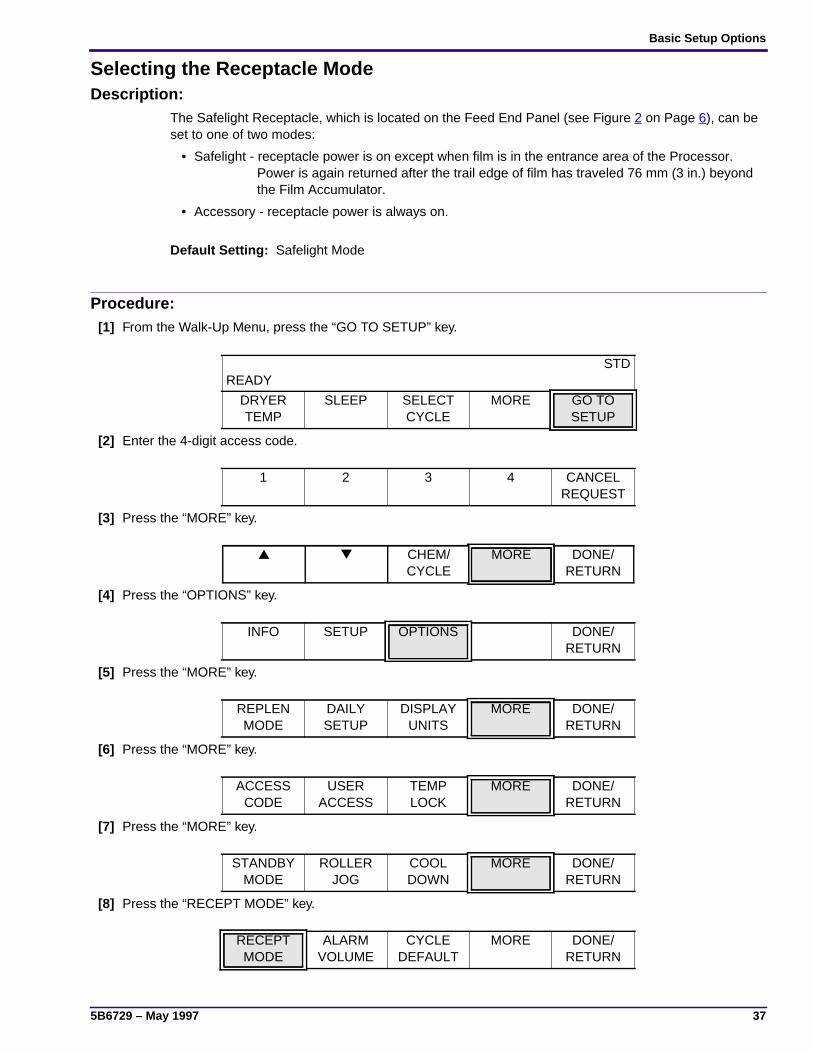
Selecting the Receptacle ModeDescription:
The Safelight Receptacle, which is located on the Feed End Panel (see Figure 2 on Page 6), can beset to one of two modes:
• Safelight - receptacle power is on except when film is in the entrance area of the Processor. Power is again returned after the trail edge of film has traveled 76 mm (3 in.) beyond the Film Accumulator.
• Accessory - receptacle power is always on.
Default Setting: Safelight Mode
Procedure:[1] From the Walk-Up Menu, press the “GO TO SETUP” key.
[2] Enter the 4-digit access code.
[3] Press the “MORE” key.
[4] Press the “OPTIONS” key.
[5] Press the “MORE” key.
[6] Press the “MORE” key.
[7] Press the “MORE” key.
[8] Press the “RECEPT MODE” key.
READYSTD
DRYERTEMP
SLEEP SELECTCYCLE
MORE GO TOSETUP
1 2 3 4 CANCELREQUEST
▲ ▼ CHEM/CYCLE
MORE DONE/RETURN
INFO SETUP OPTIONS DONE/RETURN
REPLENMODE
DAILYSETUP
DISPLAYUNITS
MORE DONE/RETURN
ACCESSCODE
USERACCESS
TEMPLOCK
MORE DONE/RETURN
STANDBYMODE
ROLLERJOG
COOLDOWN
MORE DONE/RETURN
RECEPTMODE
ALARMVOLUME
CYCLEDEFAULT
MORE DONE/RETURN

OPERATORS MANUAL
38 May 1997 – 5B6729
[9] Press either key:
• “SAFE” key for the Safelight mode or
• “ACCY” key for the Accessory mode
[10] Press the “DONE/RETURN” key repeatedly until you return to the display shown below. Then press the “YES”key to return to the Walk-Up Menu.
RECEPTACLE MODE IS SAFELIGHT
SAFE ACCY DONE/RETURN
EXIT SETUP?
YES CANCELREQUEST
Basic Setup Options
5B6729 – May 1997 39
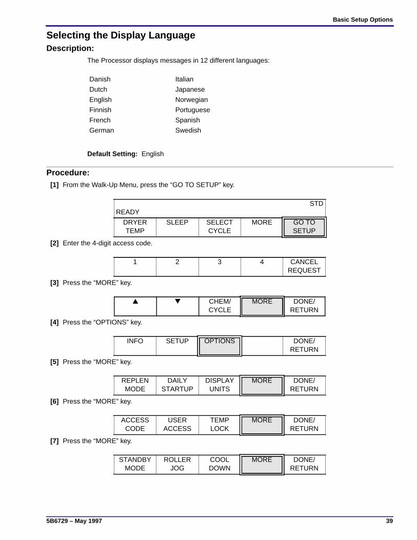
Selecting the Display LanguageDescription:
The Processor displays messages in 12 different languages:
Default Setting: English
Procedure:[1] From the Walk-Up Menu, press the “GO TO SETUP” key.
[2] Enter the 4-digit access code.
[3] Press the “MORE” key.
[4] Press the “OPTIONS” key.
[5] Press the “MORE” key.
[6] Press the “MORE” key.
[7] Press the “MORE” key.
Danish Italian
Dutch Japanese
English Norwegian
Finnish Portuguese
French Spanish
German Swedish
READYSTD
DRYERTEMP
SLEEP SELECTCYCLE
MORE GO TOSETUP
1 2 3 4 CANCELREQUEST
▲ ▼ CHEM/CYCLE
MORE DONE/RETURN
INFO SETUP OPTIONS DONE/RETURN
REPLENMODE
DAILYSTARTUP
DISPLAYUNITS
MORE DONE/RETURN
ACCESSCODE
USERACCESS
TEMPLOCK
MORE DONE/RETURN
STANDBYMODE
ROLLERJOG
COOLDOWN
MORE DONE/RETURN
OPERATORS MANUAL
40 May 1997 – 5B6729
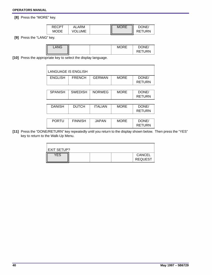
[8] Press the “MORE” key.
[9] Press the “LANG” key.
[10] Press the appropriate key to select the display language.
[11] Press the “DONE/RETURN” key repeatedly until you return to the display shown below. Then press the “YES”key to return to the Walk-Up Menu.
RECPTMODE
ALARMVOLUME
MORE DONE/RETURN
LANG MORE DONE/RETURN
LANGUAGE IS ENGLISH
ENGLISH FRENCH GERMAN MORE DONE/RETURN
SPANISH SWEDISH NORWEG MORE DONE/RETURN
DANISH DUTCH ITALIAN MORE DONE/RETURN
PORTU FINNISH JAPAN MORE DONE/RETURN
EXIT SETUP?
YES CANCELREQUEST
Advanced Setup Options
5B6729 – May 1997 41
Section 3: Advanced Setup Options
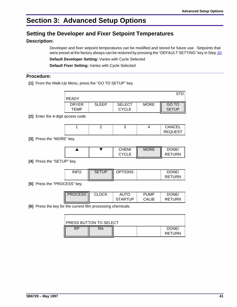
Setting the Developer and Fixer Setpoint TemperaturesDescription:
Developer and fixer setpoint temperatures can be modified and stored for future use. Setpoints thatwere preset at the factory always can be restored by pressing the “DEFAULT SETTING” key in Step 10.
Default Developer Setting: Varies with Cycle Selected
Default Fixer Setting: Varies with Cycle Selected
Procedure:[1] From the Walk-Up Menu, press the “GO TO SETUP” key.
[2] Enter the 4-digit access code.
[3] Press the “MORE” key.
[4] Press the “SETUP” key.
[5] Press the “PROCESS” key.
[6] Press the key for the current film processing chemicals.
READYSTD
DRYERTEMP
SLEEP SELECTCYCLE
MORE GO TOSETUP
1 2 3 4 CANCELREQUEST
▲ ▼ CHEM/CYCLE
MORE DONE/RETURN
INFO SETUP OPTIONS DONE/RETURN
PROCESS CLOCK AUTOSTARTUP
PUMPCALIB
DONE/RETURN
PRESS BUTTON TO SELECT
RP RA DONE/RETURN
OPERATORS MANUAL
42 May 1997 – 5B6729
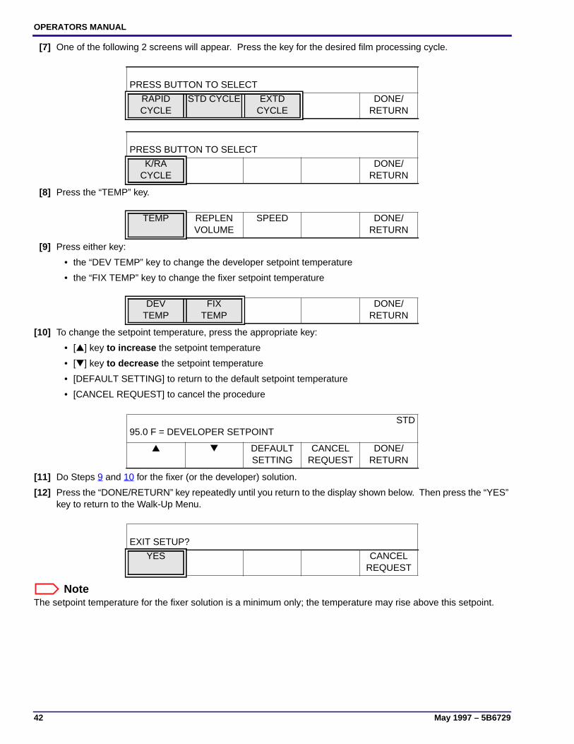
[7] One of the following 2 screens will appear. Press the key for the desired film processing cycle.
[8] Press the “TEMP” key.
[9] Press either key:
• the “DEV TEMP” key to change the developer setpoint temperature
• the “FIX TEMP” key to change the fixer setpoint temperature
[10] To change the setpoint temperature, press the appropriate key:
• [▲] key to increase the setpoint temperature
• [▼] key to decrease the setpoint temperature
• [DEFAULT SETTING] to return to the default setpoint temperature
• [CANCEL REQUEST] to cancel the procedure
[11] Do Steps 9 and 10 for the fixer (or the developer) solution.
[12] Press the “DONE/RETURN” key repeatedly until you return to the display shown below. Then press the “YES”key to return to the Walk-Up Menu.
NoteThe setpoint temperature for the fixer solution is a minimum only; the temperature may rise above this setpoint.
PRESS BUTTON TO SELECT
RAPIDCYCLE
STD CYCLE EXTDCYCLE
DONE/RETURN
PRESS BUTTON TO SELECT
K/RACYCLE
DONE/RETURN
TEMP REPLENVOLUME
SPEED DONE/RETURN
DEVTEMP
FIXTEMP
DONE/RETURN
95.0 F = DEVELOPER SETPOINTSTD
▲ ▼ DEFAULTSETTING
CANCELREQUEST
DONE/RETURN
EXIT SETUP?
YES CANCELREQUEST

Advanced Setup Options
5B6729 – May 1997 43
Displaying the Fixer TemperatureDescription:
If you wish to determine the temperature of the fixer solution, simply press the “DISPLAY FIX TEMP”key on the Display Panel. The temperature reading will then be displayed for the fixer solution.
NoteThe setpoint temperature for the fixer solution is a minimum only; the temperature may rise above thissetpoint.
Procedure:[1] From the Walk-Up Menu, press the “MORE” key.
[2] Press the “DISPLAY FIX TEMP” key.
[3] Press the “DONE/RETURN” key repeatedly until you return to the Walk-Up Menu.
READYSTD
DRYERTEMP
SLEEP SELECTCYCLE
MORE GO TOSETUP
DISPLAYFIX TMP
TIME/DATE DONE/RETURN

OPERATORS MANUAL
44 May 1997 – 5B6729
Setting the Developer and Fixer Replenishment VolumesDescription:
Default Developer Setting: Varies with the Type of Replenishment Selected (Automatic or Flooded)
Default Fixer Setting: Varies with the Type of Replenishment Selected (Automatic or Flooded)
If it is necessary to change the replenishment volumes from the factory default settings, follow theprocedure outlined below.
Procedure:[1] From the Walk-Up Menu, press the “GO TO SETUP” key.
[2] Enter the 4-digit access code.
[3] Press the “MORE” key.
[4] Press the “SETUP” key.
[5] Press the “PROCESS” key.
[6] Press the appropriate key for the desired chemicals.
READY STD
DRYERTEMP
SLEEP SELECTCYCLE
MORE GO TOSETUP
1 2 3 4 CANCELREQUEST
▲ ▼ CHEM/CYCLE
MORE DONE/RETURN
INFO SETUP OPTIONS DONE/RETURN
PROCESS CLOCK AUTOSTARTUP
PUMPCALIB
DONE/RETURN
PRESS BUTTON TO SELECT
RP RA DONE/RETURN

Advanced Setup Options
5B6729 – May 1997 45
[7] One of the following 2 screens will appear. Press the key for the desired film processing cycle.
[8] Press the “REPLEN VOLUME” key.
[9] Press the “DEV or FIX REP VOLUME” key.
[10] Press the appropriate key to change the replenishment volume:
• [▲] key to increase the volume
• [▼] key to decrease the volume
• [DEFAULT SETTING] to return to the default volume
• [CANCEL REQUEST] to cancel the procedure
[11] Press the “DONE/RETURN” key repeatedly until you return to the display shown below. Then press the “YES”key to return to the Walk-Up Menu.
PRESS BUTTON TO SELECT
RAPIDCYCLE
STD CYCLE EXTDCYCLE
DONE/RETURN
PRESS BUTTON TO SELECT
K/RACYCLE
DONE/RETURN
PRESS BUTTON TO SELECTSTD
TEMP REPLENVOLUME
SPEED DONE/RETURN
PRESS BUTTON TO SELECTSTD
DEV REPVOLUME
FIX REPVOLUME
DONE/RETURN
60 mL = FIXER REPLENISHMENT VOLUME
▲ ▼ DEFAULTSETTING
CANCELREQUEST
DONE/RETURN
EXIT SETUP?
YES CANCELREQUEST

OPERATORS MANUAL
46 May 1997 – 5B6729
Verifying the Replenishment Rates[1] Remove the Top Cover of the Processor.
[2] Insert the end of the Developer (or Fixer)Replenishment Hose into a Graduated Cylinder.
[3] Hold the Graduated Cylinder outside of theProcessor so spills will not contaminate theprocessing solutions.
[4] Press and hold for 5 seconds the ReplenishmentCalibration Switch locatednext to theReplenishment Hoses. See the figure.
[5] Allow the Replenishment Pumps to turn on anddeliver the preset volume of replenishmentsolution.
[6] Compare the volume of replenishment solutiondelivered into the Graduated Cylinder to thereplenishment volume you set in the previousprocedure. If the 2 volumes are not within 10% ofeach other, do the “Calibrating the ReplenishmentSystem” procedure on Page 26.
FIXER
DEV
H148_0112GA
FixerReplenishmentHose
GraduatedCylinder
H148_0112GCA
ReplenishmentCalibrationSwitch
QuickDisconnect
Advanced Setup Options
5B6729 – May 1997 47
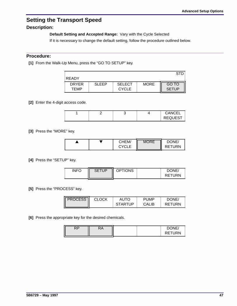
Setting the Transport SpeedDescription:
Default Setting and Accepted Range: Vary with the Cycle Selected
If it is necessary to change the default setting, follow the procedure outlined below.
Procedure:[1] From the Walk-Up Menu, press the “GO TO SETUP” key.
[2] Enter the 4-digit access code.
[3] Press the “MORE” key.
[4] Press the “SETUP” key.
[5] Press the “PROCESS” key.
[6] Press the appropriate key for the desired chemicals.
READYSTD
DRYERTEMP
SLEEP SELECTCYCLE
MORE GO TOSETUP
1 2 3 4 CANCELREQUEST
▲ ▼ CHEM/CYCLE
MORE DONE/RETURN
INFO SETUP OPTIONS DONE/RETURN
PROCESS CLOCK AUTOSTARTUP
PUMPCALIB
DONE/RETURN
RP RA DONE/RETURN
OPERATORS MANUAL
48 May 1997 – 5B6729
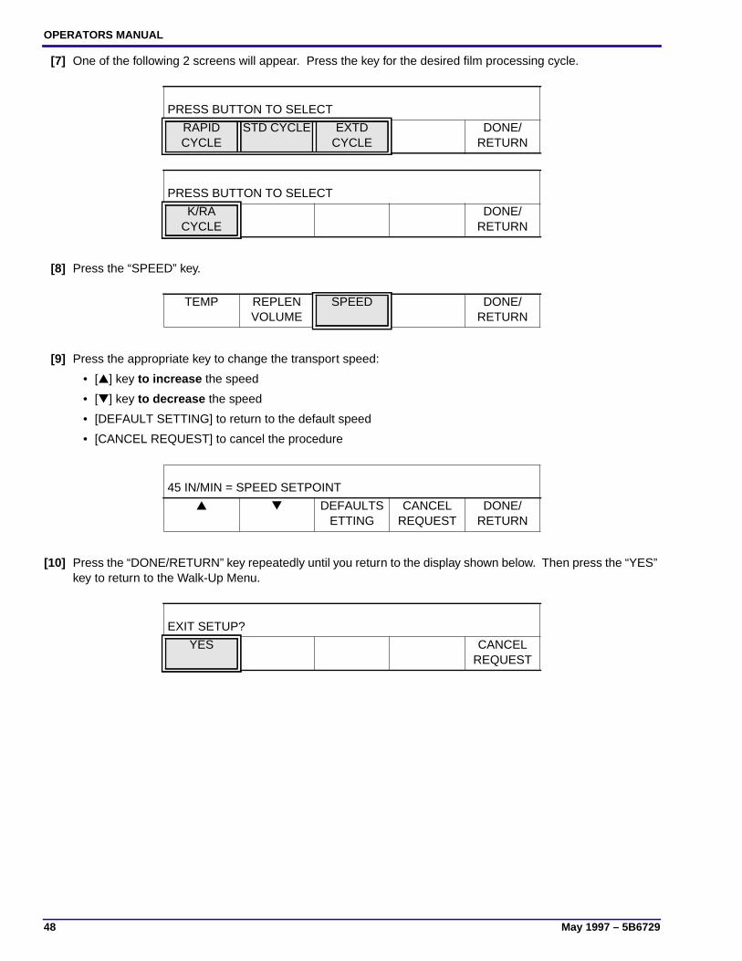
[7] One of the following 2 screens will appear. Press the key for the desired film processing cycle.
[8] Press the “SPEED” key.
[9] Press the appropriate key to change the transport speed:
• [▲] key to increase the speed
• [▼] key to decrease the speed
• [DEFAULT SETTING] to return to the default speed
• [CANCEL REQUEST] to cancel the procedure
[10] Press the “DONE/RETURN” key repeatedly until you return to the display shown below. Then press the “YES”key to return to the Walk-Up Menu.
PRESS BUTTON TO SELECT
RAPIDCYCLE
STD CYCLE EXTDCYCLE
DONE/RETURN
PRESS BUTTON TO SELECT
K/RACYCLE
DONE/RETURN
TEMP REPLENVOLUME
SPEED DONE/RETURN
45 IN/MIN = SPEED SETPOINT
▲ ▼ DEFAULTSETTING
CANCELREQUEST
DONE/RETURN
EXIT SETUP?
YES CANCELREQUEST

Advanced Setup Options
5B6729 – May 1997 49
Setting the Automatic On and Off TimersDescription:
The Processor software provides programmable timers for programming 2 distinct on and off times forthe Processor each day. The Automatic Timers allow you to specify a start time for the Processor toenergize automatically so that the processing solutions and the Dryer will have reached their setpointtemperatures before you arrive at the work site. The Processor can store up to 2 “start times” and 2“off times” for each day of the week to coincide with changing shifts or with weekend schedules.
Example of Use: For instance, if you want the Processor to be warmed up and ready to accept filmsby the time you arrive at work in the morning, you may set Timer1 to turn on the Processor at 6:00 a.m.If you operate during 2 distinct shifts and there is a large lapse in time between the 2 shifts, you mightwant to set Timer1 to turn off the Processor at the end of the first shift and set Timer2 to turn on theProcessor again an hour before the second shift starts for the afternoon. And finally, you might wantto set Timer2 to turn off the Processor for the night at the end of the second shift.
ImportantWhen you are setting the Timers, if the current time is later than the programmed “off time”, theProcessor will not automatically turn itself off until that time the following day.
You will have to manually turn off the Processor for the current day. For example:If it is currently 4:00 p.m. and you have programmed the “off time” for 3:00 p.m., you must manually turnoff the Processor.
Do not set the On and Off Timers within 15 minutes of each other. To ensure the correct operation ofthe Processor, the Processor must remain on for at least 15 minutes before the Automatic Off Timerturns it off. Likewise, the Processor must remain off for at least 15 minutes before the Automatic OnTimer turns it on.
Procedure for Setting Timer1 Initially
Beginning the Procedure
NoteIf the Timers are already set and you wish to change the on and off times, follow the procedure on Page 54.
Before proceeding with the steps below, be sure that you have completed the procedure for setting the time and dateon Page 23.
If you are reading through the steps below to become familiar with the procedure and are not actually setting thetimers, the screens that you see displayed may be different from the sample screens shown in this procedure.
[1] From the Walk-Up Menu, press the “GO TO SETUP” key.
[2] Enter the 4-digit access code.
READYSTD
DRYERTEMP
SLEEP SELECTCYCLE
MORE GO TOSETUP
1 2 3 4 CANCELREQUEST

OPERATORS MANUAL
50 May 1997 – 5B6729
[3] Press the “MORE” key.
[4] Press the “SETUP” key.
[5] Press the “AUTO STARTUP” key.
[6] If you have already set the clock, continue with Step 7. If you have not yet set the time and date, the displaybelow will appear. Do the procedure on Page 23 before continuing with this procedure.
[7] Press the “ON” key.
[8] Press the “SET TIMERS” key.
Setting the On Time:
[9] Press the“TIMER1 CONTROL” key.
[10] Press the “ON” key.
▲ ▼ CHEM/CYCLE
MORE DONE/RETURN
INFO SETUP OPTIONS DONE/RETURN
PROCESS CLOCK AUTOSTARTUP
PUMPCALIB
DONE/RETURN
CLOCK MUST BE SET BEFORE CONTINUING
DONE/RETURN
AUTO STARTUP IS OFF
ON OFF DONE/RETURN
AUTO STARTUP IS ON
SETTIMERS
ON OFF DONE/RETURN
PRESS BUTTON TO SET UP FOR MONDAY
TIMER1CONTROL
COPYPREV
NEXTDAY
DONE/RETURN
SET UP TIMER1 FOR MONDAY
ON OFF DONE/RETURN

Advanced Setup Options
5B6729 – May 1997 51
[11] Press the “ON TIME” key.
[12] Use the up and down arrow keys to select the hour and minute when you want the Processor to turn on.
[13] Press the “DONE/RETURN” key to return to the menu options shown below.
Setting the Off Time:
NoteAny time the screen shown below appears on the Display Panel, you can press the “OFF” key to erase the lastprogrammed on and off times for Timer1 and Timer2.
[14] Press the “OFF TIME” key.
[15] Use the up and down arrow keys to select the hour and minute when you want the Processor to turn off.
[16] Press the “DONE/RETURN” key repeatedly until you return to the menu options shown below.
SET UP TIMER1 FOR MONDAY
ONTIME
ON OFF DONE/RETURN
6:00 AM = CURRENT ON TIME
▲
HOUR▼
HOUR▲
MINUTE▼
MINUTEDONE/
RETURN
SET UP TIMER1 FOR MONDAY
ONTIME
OFFTIME
ON OFF DONE/RETURN
SET UP TIMER1 FOR MONDAY
ONTIME
OFFTIME
ON OFF DONE/RETURN
11:00 AM = CURRENT OFF TIME
▲
HOUR▼
HOUR▲
MINUTE▼
MINUTEDONE/
RETURN
PRESS BUTTON TO SET UP FOR MONDAY
TIMER1CONTROL
TIMER2CONTROL
COPYPREV
NEXTDAY
DONE/RETURN

OPERATORS MANUAL
52 May 1997 – 5B6729
Procedure for Setting Timer2 Initially[1] Press the “TIMER2 CONTROL” key.
[2] Repeat Steps 10 through 16 starting on Page 50 to set the on and off times for Timer2. Then set the on andoff times for the remaining days of the week by completing the steps on the next page.
Procedure for Setting the On and Off Timers for the Remaining Days of the Week
Introduction
If the hours that you would like to operate the Processor on the other days of the week are the same hours as thoseyou set for Monday, follow Steps 1 through 3 below.
If you do not want to repeat Monday’s on and off times for the other days of the week, follow Steps 4 through 13.
Copying On and Off Timer Settings:
[1] Press the “NEXT DAY” key to advance the display to show Tuesday.
[2] Press the “COPY PREV” key. You will hear a beep when you press the “COPY PREV” key.
[3] Repeat the entire process to set the Automatic Timers for the remaining days of the week.
Setting Different On and Off Times for the Remaining Days:
If you want to select different on and off times for Timer1 and Timer2 than those you set for Monday, do the stepsbelow.
[4] Press the “NEXT DAY” key to advance the display to show Tuesday.
[5] Press the “TIMER1 CONTROL” key.
[6] Press the “ON” key to enable Timer1.
PRESS BUTTON TO SET UP FOR MONDAY
TIMER1CONTROL
TIMER2CONTROL
COPYPREV
NEXTDAY
DONE/RETURN
PRESS BUTTON TO SET UP FOR MONDAY
TIMER1CONTROL
TIMER2CONTROL
COPYPREV
NEXTDAY
DONE/RETURN
PRESS BUTTON TO SET UP FOR TUESDAY
TIMER1CONTROL
COPYPREV
NEXTDAY
DONE/RETURN
PRESS BUTTON TO SET UP FOR MONDAY
TIMER1CONTROL
COPYPREV
NEXTDAY
DONE/RETURN
PRESS BUTTON TO SET UP FOR TUESDAY
TIMER1CONTROL
COPYPREV
NEXTDAY
DONE/RETURN

Advanced Setup Options
5B6729 – May 1997 53
[7] Press the “ON TIME” key.
[8] Use the up and down arrow keys to select the hour and minute when you want the Processor to turn on.
[9] Press the “DONE/RETURN” key until you return to the menu options shown below.Press the “OFF TIME” key.
[10] Use the up and down arrow keys to select the hour and minute when you want the Processor to turn off.
[11] Press the “DONE/RETURN” key twice to return to the menu options displayed below.Press the “TIMER2 CONTROL” key.
[12] Repeat Steps 7 through 11 to set the on and off time settings for Timer2.
[13] Repeat the entire process to set the Automatic Timers for the remaining days of the week.
SET UP TIMER1 FOR MONDAY
ON OFF DONE/RETURN
SET UP TIMER1 FOR TUESDAY
ONTIME
ON OFF DONE/RETURN
2:00 PM = CURRENT ON TIME
▲
HOUR▼
HOUR▲
MINUTE▼
MINUTEDONE/
RETURN
SET UP TIMER1 FOR TUESDAY
ONTIME
OFFTIME
ON OFF DONE/RETURN
11:00 PM = CURRENT OFF TIME
▲
HOUR▼
HOUR▲
MINUTE▼
MINUTEDONE/
RETURN
PRESS BUTTON TO SET UP FOR TUESDAY
TIMER1CONTROL
TIMER2CONTROL
COPYPREV
NEXTDAY
DONE/RETURN

OPERATORS MANUAL
54 May 1997 – 5B6729
Changing the On and Off Timer Settings
NoteIf you are setting the On and Off Timer Settings for the very first time, follow the procedure on Page 49.
[1] From the Walk-Up Menu, press the “GO TO SETUP” key.
[2] Enter the 4-digit access code.
[3] Press the “MORE” key.
[4] Press the “SETUP” key.
[5] Press the “AUTO STARTUP” key.
[6] Press the “SET TIMERS” key.
[7] Press either the “TIMER1 CONTROL” or “TIMER2 CONTROL” key.
[8] Press either the “ON TIME” or the “OFF TIME” key.
READYSTD
DRYERTEMP
SLEEP SELECTCYCLE
MORE GO TOSETUP
1 2 3 4 CANCELREQUEST
▲ ▼ CHEM/CYCLE
MORE DONE/RETURN
INFO SETUP OPTIONS DONE/RETURN
PROCESS CLOCK AUTOSTARTUP
PUMPCALIB
DONE/RETURN
AUTO STARTUP IS ON
SETTIMERS
ON OFF DONE/RETURN
PRESS BUTTON TO SET UP FOR MONDAY
TIMER1CONTROL
TIMER2CONTROL
COPYPREV
NEXTDAY
DONE/RETURN
SET UP TIMER1 FOR MONDAY
ONTIME
OFFTIME
ON OFF DONE/RETURN

Advanced Setup Options
5B6729 – May 1997 55
[9] Use the up and down arrow keys to select the new time that you want to program.
[10] Continue changing the programmed on and off times for Timer1 and Timer2 by pressing the “DONE/RETURN”key repeatedly until you return to the appropriate menu.
NoteAny time the screen shown above appears on the Display Panel, you can press the “OFF” key to erase the lastprogrammed on and off times for Timer1 and Timer2.
[11] When you are through changing the on and off times, press the “DONE/RETURN” key repeatedly until youreturn to the display shown below. Then press the “YES” key to return to the Walk-Up Menu.
6:00 AM = CURRENT ON TIME
▲
HOUR▼
HOUR▲
MINUTE▼
MINUTEDONE/
RETURN
SET UP TIMER1 FOR MONDAY
ONTIME
OFFTIME
ON OFF DONE/RETURN
EXIT SETUP?
YES CANCELREQUEST
OPERATORS MANUAL
56 May 1997 – 5B6729
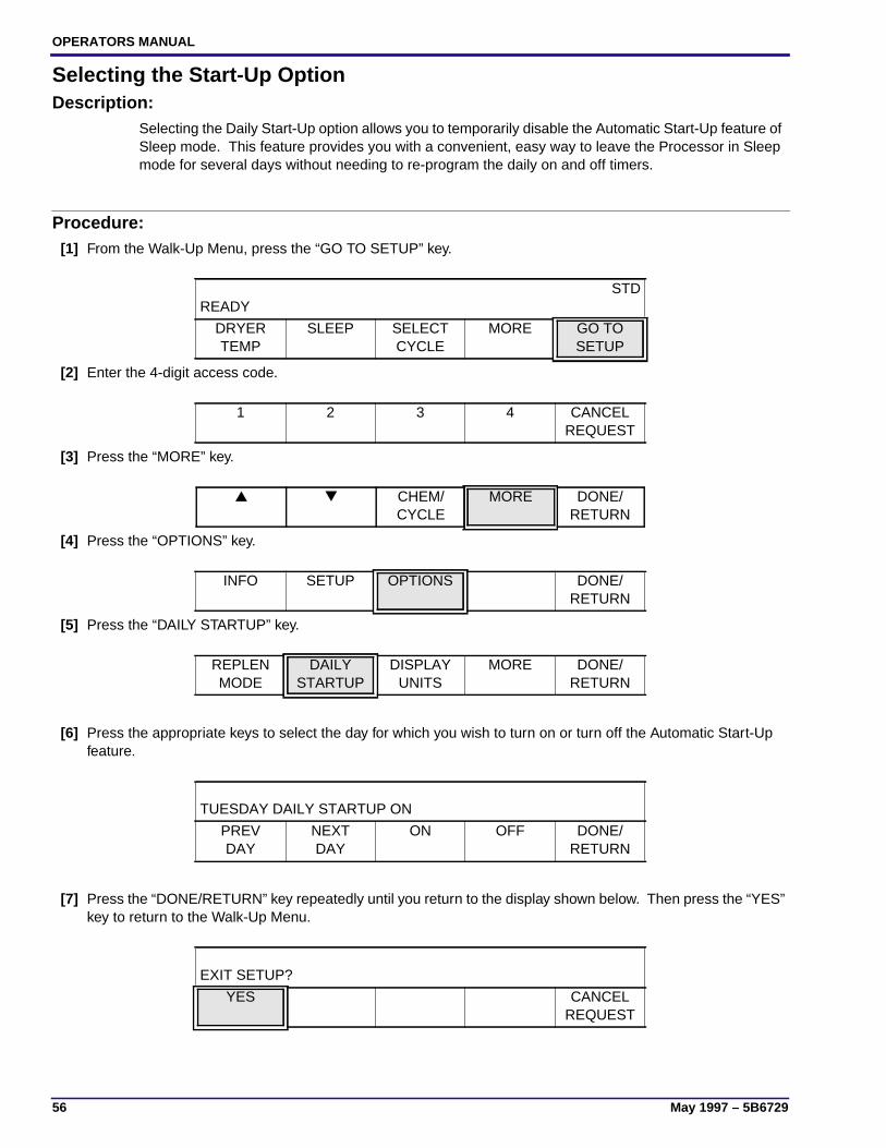
Selecting the Start-Up OptionDescription:
Selecting the Daily Start-Up option allows you to temporarily disable the Automatic Start-Up feature ofSleep mode. This feature provides you with a convenient, easy way to leave the Processor in Sleepmode for several days without needing to re-program the daily on and off timers.
Procedure:[1] From the Walk-Up Menu, press the “GO TO SETUP” key.
[2] Enter the 4-digit access code.
[3] Press the “MORE” key.
[4] Press the “OPTIONS” key.
[5] Press the “DAILY STARTUP” key.
[6] Press the appropriate keys to select the day for which you wish to turn on or turn off the Automatic Start-Upfeature.
[7] Press the “DONE/RETURN” key repeatedly until you return to the display shown below. Then press the “YES”key to return to the Walk-Up Menu.
READYSTD
DRYERTEMP
SLEEP SELECTCYCLE
MORE GO TOSETUP
1 2 3 4 CANCELREQUEST
▲ ▼ CHEM/CYCLE
MORE DONE/RETURN
INFO SETUP OPTIONS DONE/RETURN
REPLENMODE
DAILYSTARTUP
DISPLAYUNITS
MORE DONE/RETURN
TUESDAY DAILY STARTUP ON
PREVDAY
NEXTDAY
ON OFF DONE/RETURN
EXIT SETUP?
YES CANCELREQUEST

Advanced Setup Options
5B6729 – May 1997 57
Entering and Exiting Sleep Mode
Description:Figure 10
When the Processor is in Sleep mode, the Processorappears to be “off,” but the microprocessor remainsactive. Depending upon the configuration of otheroptions, the components listed below remain off whilethe Processor is in Sleep mode:
• Heaters
• Motors
• Solenoids
While the Processor is in the Sleep mode, you cannotfeed films or access any of the Processor setupscreens.
You can manually place the Processor in or out ofSleep mode in either of 2 ways:
• Simply use the Key located on the feed end of theProcessor.
• Or, use the Soft Keys on the Display Panel to placethe Processor into or out of Sleep Mode.
NoteTo fully utilize the Sleep Mode, the Cool Down, and theRoller Jog features, you must:
1. Leave the main Circuit Breaker CB1 and the wallPower Switch in the “ON” positions.
2. Leave the water supply on.
3. Leave the Top Cover closed.
H148_0108CA
K R S E
P.I.C. INTERFACE
Sleep/
PanelControlInterface
Breaker CB1Main Circuit
ReceptacleSafelight
Status IndicatorsCycle Indicators
H148_0108CCA
WakeKey
CycleKey
OPERATORS MANUAL
58 May 1997 – 5B6729
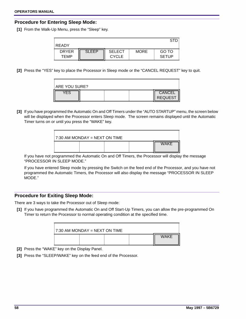
Procedure for Entering Sleep Mode:[1] From the Walk-Up Menu, press the “Sleep” key.
[2] Press the “YES” key to place the Processor in Sleep mode or the “CANCEL REQUEST” key to quit.
[3] If you have programmed the Automatic On and Off Timers under the “AUTO STARTUP” menu, the screen belowwill be displayed when the Processor enters Sleep mode. The screen remains displayed until the AutomaticTimer turns on or until you press the “WAKE” key.
If you have not programmed the Automatic On and Off Timers, the Processor will display the message“PROCESSOR IN SLEEP MODE.”
If you have entered Sleep mode by pressing the Switch on the feed end of the Processor, and you have notprogrammed the Automatic Timers, the Processor will also display the message “PROCESSOR IN SLEEPMODE.”
Procedure for Exiting Sleep Mode:There are 3 ways to take the Processor out of Sleep mode:
[1] If you have programmed the Automatic On and Off Start-Up Timers, you can allow the pre-programmed OnTimer to return the Processor to normal operating condition at the specified time.
[2] Press the “WAKE” key on the Display Panel.
[3] Press the “SLEEP/WAKE” key on the feed end of the Processor.
READYSTD
DRYERTEMP
SLEEP SELECTCYCLE
MORE GO TOSETUP
ARE YOU SURE?
YES CANCELREQUEST
7:30 AM MONDAY = NEXT ON TIME
WAKE
7:30 AM MONDAY = NEXT ON TIME
WAKE
Advanced Setup Options
5B6729 – May 1997 59
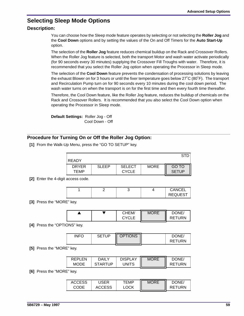
Selecting Sleep Mode OptionsDescription:
You can choose how the Sleep mode feature operates by selecting or not selecting the Roller Jog andthe Cool Down options and by setting the values of the On and Off Timers for the Auto Start-Upoption.
The selection of the Roller Jog feature reduces chemical buildup on the Rack and Crossover Rollers.When the Roller Jog feature is selected, both the transport Motor and wash water activate periodically(for 90 seconds every 30 minutes) supplying the Crossover Fill Troughs with water. Therefore, it isrecommended that you select the Roller Jog option when operating the Processor in Sleep mode.
The selection of the Cool Down feature prevents the condensation of processing solutions by leavingthe exhaust Blower on for 3 hours or until the fixer temperature goes below 27˚C (80˚F). The transportand Recirculation Pump turn on for 90 seconds every 10 minutes during the cool down period. Thewash water turns on when the transport is on for the first time and then every fourth time thereafter.
Therefore, the Cool Down feature, like the Roller Jog feature, reduces the buildup of chemicals on theRack and Crossover Rollers. It is recommended that you also select the Cool Down option whenoperating the Processor in Sleep mode.
Default Settings: Roller Jog - Off Cool Down - Off
Procedure for Turning On or Off the Roller Jog Option:[1] From the Walk-Up Menu, press the “GO TO SETUP” key.
[2] Enter the 4-digit access code.
[3] Press the “MORE” key.
[4] Press the “OPTIONS” key.
[5] Press the “MORE” key.
[6] Press the “MORE” key.
READYSTD
DRYERTEMP
SLEEP SELECTCYCLE
MORE GO TOSETUP
1 2 3 4 CANCELREQUEST
▲ ▼ CHEM/CYCLE
MORE DONE/RETURN
INFO SETUP OPTIONS DONE/RETURN
REPLENMODE
DAILYSTARTUP
DISPLAYUNITS
MORE DONE/RETURN
ACCESSCODE
USERACCESS
TEMPLOCK
MORE DONE/RETURN

OPERATORS MANUAL
60 May 1997 – 5B6729
[7] Press the “ROLLER JOG” key.
[8] Press either key:
• the “ON” key to enable the Roller Jog option
• the “OFF” key to disable the Roller Jog option
[9] Press the “DONE/RETURN” key repeatedly until you return to the display shown below. Then press the “YES”key to return to the Walk-Up Menu.
STANDBYMODE
ROLLERJOG
COOLDOWN
MORE DONE/RETURN
ON OFF DONE/RETURN
EXIT SETUP?
YES CANCELREQUEST
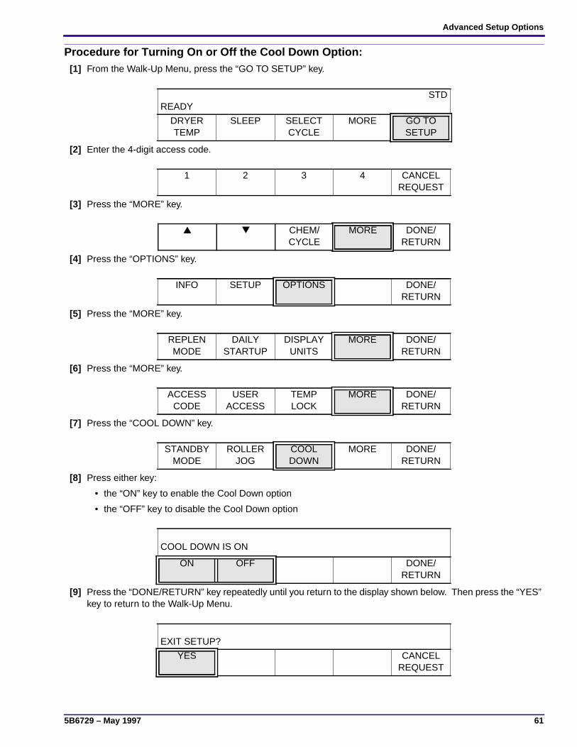
Advanced Setup Options
5B6729 – May 1997 61
Procedure for Turning On or Off the Cool Down Option:[1] From the Walk-Up Menu, press the “GO TO SETUP” key.
[2] Enter the 4-digit access code.
[3] Press the “MORE” key.
[4] Press the “OPTIONS” key.
[5] Press the “MORE” key.
[6] Press the “MORE” key.
[7] Press the “COOL DOWN” key.
[8] Press either key:
• the “ON” key to enable the Cool Down option
• the “OFF” key to disable the Cool Down option
[9] Press the “DONE/RETURN” key repeatedly until you return to the display shown below. Then press the “YES”key to return to the Walk-Up Menu.
READYSTD
DRYERTEMP
SLEEP SELECTCYCLE
MORE GO TOSETUP
1 2 3 4 CANCELREQUEST
▲ ▼ CHEM/CYCLE
MORE DONE/RETURN
INFO SETUP OPTIONS DONE/RETURN
REPLENMODE
DAILYSTARTUP
DISPLAYUNITS
MORE DONE/RETURN
ACCESSCODE
USERACCESS
TEMPLOCK
MORE DONE/RETURN
STANDBYMODE
ROLLERJOG
COOLDOWN
MORE DONE/RETURN
COOL DOWN IS ON
ON OFF DONE/RETURN
EXIT SETUP?
YES CANCELREQUEST
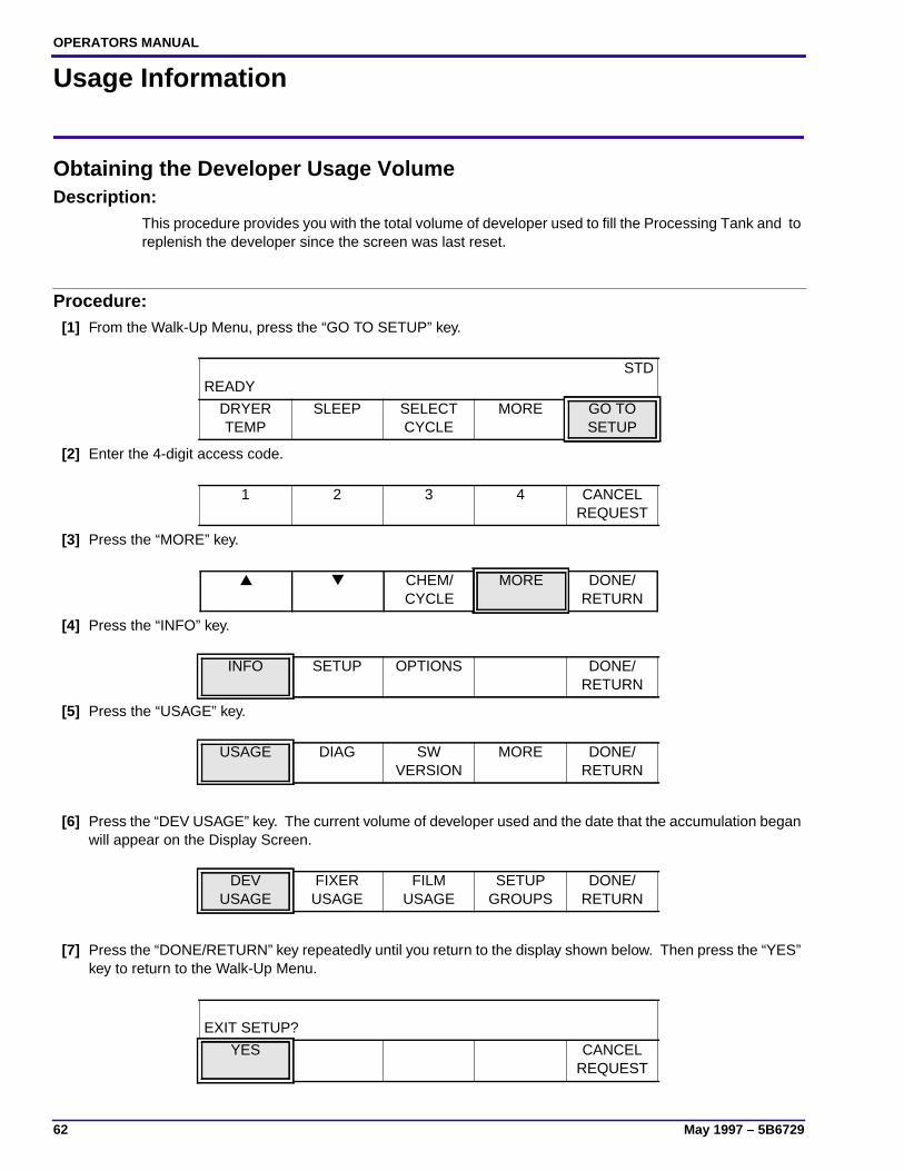
OPERATORS MANUAL
62 May 1997 – 5B6729
Usage Information
Obtaining the Developer Usage VolumeDescription:
This procedure provides you with the total volume of developer used to fill the Processing Tank and toreplenish the developer since the screen was last reset.
Procedure:[1] From the Walk-Up Menu, press the “GO TO SETUP” key.
[2] Enter the 4-digit access code.
[3] Press the “MORE” key.
[4] Press the “INFO” key.
[5] Press the “USAGE” key.
[6] Press the “DEV USAGE” key. The current volume of developer used and the date that the accumulation beganwill appear on the Display Screen.
[7] Press the “DONE/RETURN” key repeatedly until you return to the display shown below. Then press the “YES”key to return to the Walk-Up Menu.
READYSTD
DRYERTEMP
SLEEP SELECTCYCLE
MORE GO TOSETUP
1 2 3 4 CANCELREQUEST
▲ ▼ CHEM/CYCLE
MORE DONE/RETURN
INFO SETUP OPTIONS DONE/RETURN
USAGE DIAG SWVERSION
MORE DONE/RETURN
DEVUSAGE
FIXERUSAGE
FILMUSAGE
SETUPGROUPS
DONE/RETURN
EXIT SETUP?
YES CANCELREQUEST
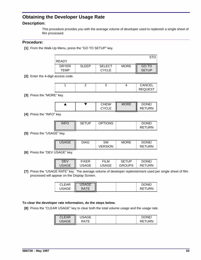
5B6729 – May 1997 63
Obtaining the Developer Usage RateDescription:
This procedure provides you with the average volume of developer used to replenish a single sheet offilm processed.
Procedure:[1] From the Walk-Up Menu, press the “GO TO SETUP” key.
[2] Enter the 4-digit access code.
[3] Press the “MORE” key.
[4] Press the “INFO” key.
[5] Press the “USAGE” key.
[6] Press the “DEV USAGE” key.
[7] Press the “USAGE RATE” key. The average volume of developer replenishment used per single sheet of filmprocessed will appear on the Display Screen.
To clear the developer rate information, do the steps below.
[8] Press the “CLEAR USAGE” key to clear both the total volume usage and the usage rate.
READYSTD
DRYERTEMP
SLEEP SELECTCYCLE
MORE GO TOSETUP
1 2 3 4 CANCELREQUEST
▲ ▼ CHEM/CYCLE
MORE DONE/RETURN
INFO SETUP OPTIONS DONE/RETURN
USAGE DIAG SWVERSION
MORE DONE/RETURN
DEVUSAGE
FIXERUSAGE
FILMUSAGE
SETUPGROUPS
DONE/RETURN
CLEARUSAGE
USAGERATE
DONE/RETURN
CLEARUSAGE
USAGERATE
DONE/RETURN
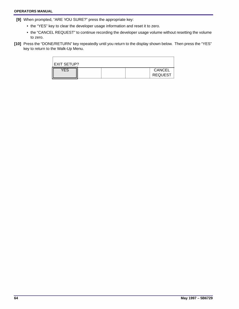
OPERATORS MANUAL
64 May 1997 – 5B6729
[9] When prompted, “ARE YOU SURE?” press the appropriate key:
• the “YES” key to clear the developer usage information and reset it to zero.
• the “CANCEL REQUEST” to continue recording the developer usage volume without resetting the volumeto zero.
[10] Press the “DONE/RETURN” key repeatedly until you return to the display shown below. Then press the “YES”key to return to the Walk-Up Menu.
EXIT SETUP?
YES CANCELREQUEST
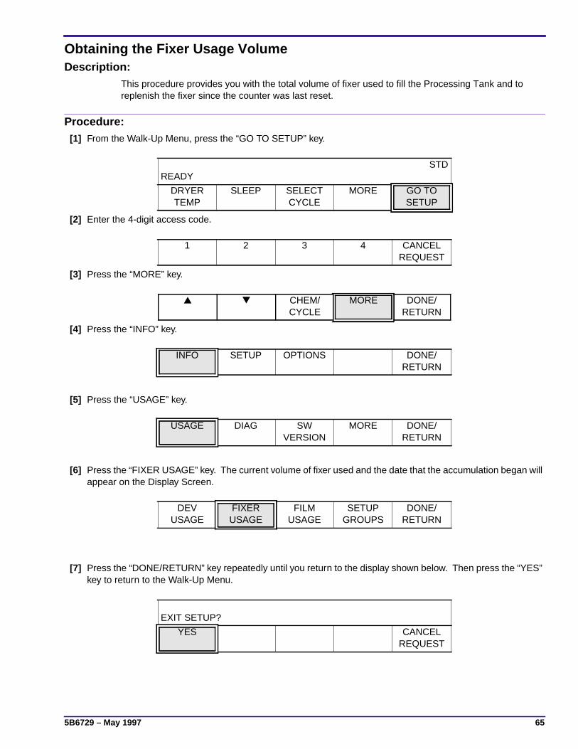
5B6729 – May 1997 65
Obtaining the Fixer Usage VolumeDescription:
This procedure provides you with the total volume of fixer used to fill the Processing Tank and toreplenish the fixer since the counter was last reset.
Procedure:[1] From the Walk-Up Menu, press the “GO TO SETUP” key.
[2] Enter the 4-digit access code.
[3] Press the “MORE” key.
[4] Press the “INFO” key.
[5] Press the “USAGE” key.
[6] Press the “FIXER USAGE” key. The current volume of fixer used and the date that the accumulation began willappear on the Display Screen.
[7] Press the “DONE/RETURN” key repeatedly until you return to the display shown below. Then press the “YES”key to return to the Walk-Up Menu.
READYSTD
DRYERTEMP
SLEEP SELECTCYCLE
MORE GO TOSETUP
1 2 3 4 CANCELREQUEST
▲ ▼ CHEM/CYCLE
MORE DONE/RETURN
INFO SETUP OPTIONS DONE/RETURN
USAGE DIAG SWVERSION
MORE DONE/RETURN
DEVUSAGE
FIXERUSAGE
FILMUSAGE
SETUPGROUPS
DONE/RETURN
EXIT SETUP?
YES CANCELREQUEST
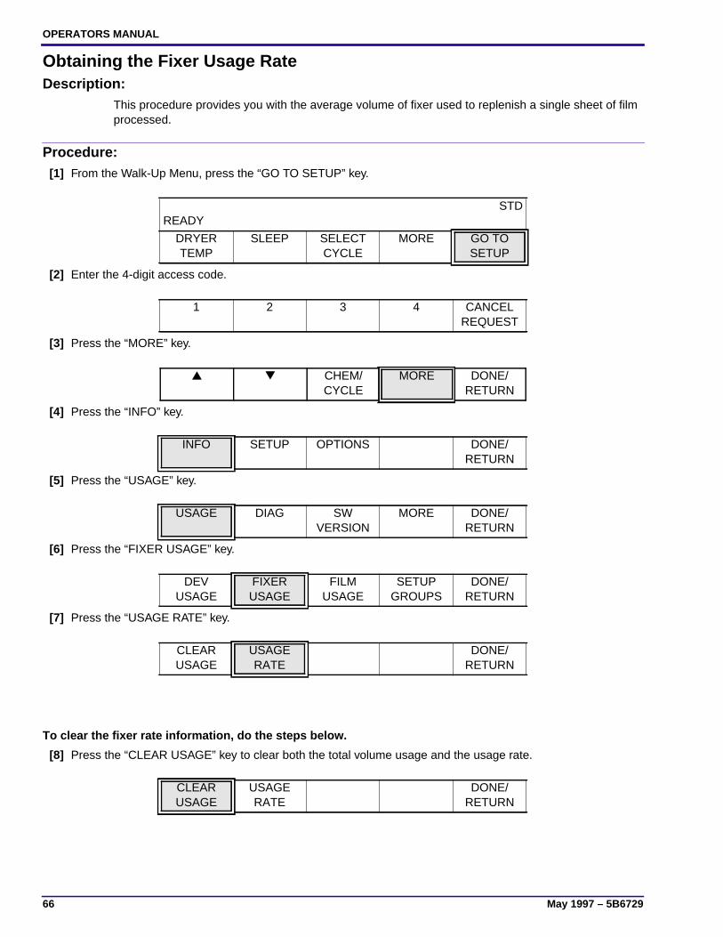
OPERATORS MANUAL
66 May 1997 – 5B6729
Obtaining the Fixer Usage RateDescription:
This procedure provides you with the average volume of fixer used to replenish a single sheet of filmprocessed.
Procedure:[1] From the Walk-Up Menu, press the “GO TO SETUP” key.
[2] Enter the 4-digit access code.
[3] Press the “MORE” key.
[4] Press the “INFO” key.
[5] Press the “USAGE” key.
[6] Press the “FIXER USAGE” key.
[7] Press the “USAGE RATE” key.
To clear the fixer rate information, do the steps below.
[8] Press the “CLEAR USAGE” key to clear both the total volume usage and the usage rate.
READYSTD
DRYERTEMP
SLEEP SELECTCYCLE
MORE GO TOSETUP
1 2 3 4 CANCELREQUEST
▲ ▼ CHEM/CYCLE
MORE DONE/RETURN
INFO SETUP OPTIONS DONE/RETURN
USAGE DIAG SWVERSION
MORE DONE/RETURN
DEVUSAGE
FIXERUSAGE
FILMUSAGE
SETUPGROUPS
DONE/RETURN
CLEARUSAGE
USAGERATE
DONE/RETURN
CLEARUSAGE
USAGERATE
DONE/RETURN

5B6729 – May 1997 67
[9] When prompted, “ARE YOU SURE?” press the appropriate key:
• the “YES” key to clear the developer usage information and reset it to zero.
• the “CANCEL REQUEST” to continue recording the developer usage volume without resetting the volumeto zero.
[10] Press the “DONE/RETURN” key repeatedly until you return to the display shown below. Then press the “YES”key to return to the Walk-Up Menu.
EXIT SETUP?
YES CANCELREQUEST
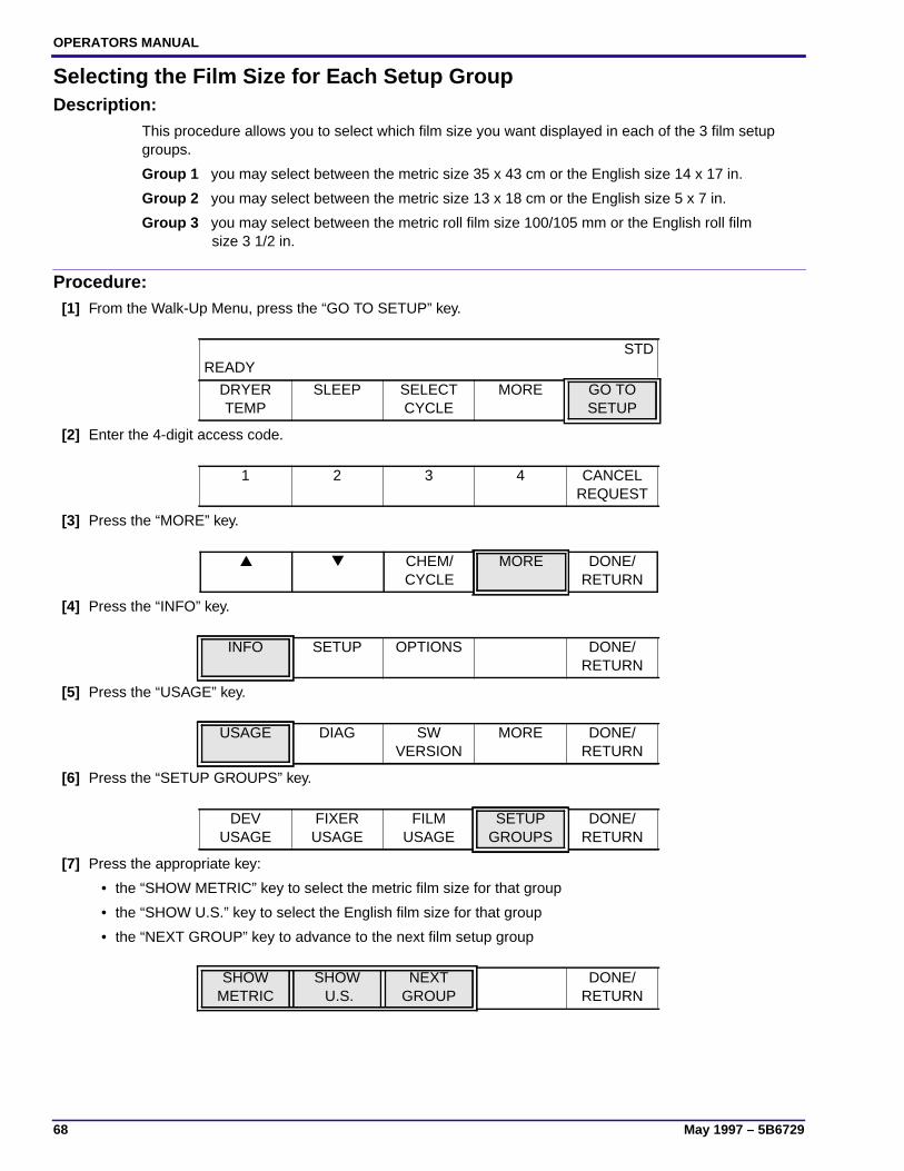
OPERATORS MANUAL
68 May 1997 – 5B6729
Selecting the Film Size for Each Setup GroupDescription:
This procedure allows you to select which film size you want displayed in each of the 3 film setupgroups.
Group 1 you may select between the metric size 35 x 43 cm or the English size 14 x 17 in.
Group 2 you may select between the metric size 13 x 18 cm or the English size 5 x 7 in.
Group 3 you may select between the metric roll film size 100/105 mm or the English roll film size 3 1/2 in.
Procedure:[1] From the Walk-Up Menu, press the “GO TO SETUP” key.
[2] Enter the 4-digit access code.
[3] Press the “MORE” key.
[4] Press the “INFO” key.
[5] Press the “USAGE” key.
[6] Press the “SETUP GROUPS” key.
[7] Press the appropriate key:
• the “SHOW METRIC” key to select the metric film size for that group
• the “SHOW U.S.” key to select the English film size for that group
• the “NEXT GROUP” key to advance to the next film setup group
READYSTD
DRYERTEMP
SLEEP SELECTCYCLE
MORE GO TOSETUP
1 2 3 4 CANCELREQUEST
▲ ▼ CHEM/CYCLE
MORE DONE/RETURN
INFO SETUP OPTIONS DONE/RETURN
USAGE DIAG SWVERSION
MORE DONE/RETURN
DEVUSAGE
FIXERUSAGE
FILMUSAGE
SETUPGROUPS
DONE/RETURN
SHOWMETRIC
SHOW U.S.
NEXTGROUP
DONE/RETURN
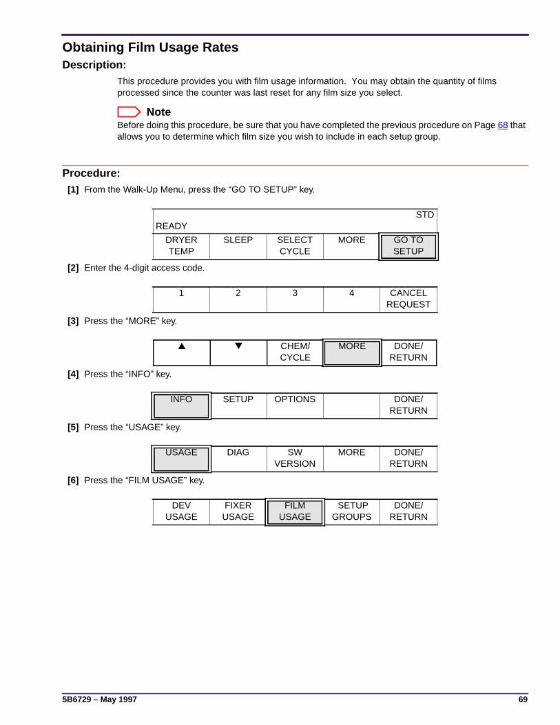
5B6729 – May 1997 69
Obtaining Film Usage RatesDescription:
This procedure provides you with film usage information. You may obtain the quantity of filmsprocessed since the counter was last reset for any film size you select.
NoteBefore doing this procedure, be sure that you have completed the previous procedure on Page 68 thatallows you to determine which film size you wish to include in each setup group.
Procedure:[1] From the Walk-Up Menu, press the “GO TO SETUP” key.
[2] Enter the 4-digit access code.
[3] Press the “MORE” key.
[4] Press the “INFO” key.
[5] Press the “USAGE” key.
[6] Press the “FILM USAGE” key.
READYSTD
DRYERTEMP
SLEEP SELECTCYCLE
MORE GO TOSETUP
1 2 3 4 CANCELREQUEST
▲ ▼ CHEM/CYCLE
MORE DONE/RETURN
INFO SETUP OPTIONS DONE/RETURN
USAGE DIAG SWVERSION
MORE DONE/RETURN
DEVUSAGE
FIXERUSAGE
FILMUSAGE
SETUPGROUPS
DONE/RETURN

OPERATORS MANUAL
70 May 1997 – 5B6729
[7] Press the appropriate key:
• the “▲” key to display the usage count for the next largest film size
• the “▼” key to display the usage count for the next smallest film size
• the “SHEET COUNT” key to display the total number of films processed (all sizes)
To clear the film usage information, do the steps below.
[8] Press the “CLEAR USAGE” key.
[9] When prompted, “ARE YOU SURE?” press the appropriate key:
• the “YES” key to clear the film usage information and reset it to zero (for all film sizes).
• the “CANCEL REQUEST” to continue recording the film usage information without resetting it to zero.
[10] Press the “DONE/RETURN” key repeatedly until you return to the display shown below. Then press the “YES”key to return to the Walk-Up Menu.
▲ ▼ CLEARUSAGE
SHEETCOUNT
DONE/RETURN
▲ ▼ CLEARUSAGE
SHEETCOUNT
DONE/RETURN
EXIT SETUP?
YES CANCELREQUEST

5B6729 – May 1997 71
Obtaining the Processor’s Software VersionDescription:
This procedure allows you to determine what versions of software are operating in your Processor. Youmay display the software version for the following programs:
• Boot
• Main
• Accumulator Boot
• Accumulator Main
Procedure:[1] From the Walk-Up Menu, press the “GO TO SETUP” key.
[2] Enter the 4-digit access code.
[3] Press the “MORE” key.
[4] Press the “INFO” key.
[5] Press the “SW VERSION” key.
[6] Press the appropriate key. The software version will appear on the Display Screen.
• the “BOOT” key to display the boot version
• the “MAIN” key to display the main program version
• the “ACCUM BOOT” key to display the accumulator boot version
• the “ACCUM MAIN” key to display the accumulator main program version
[7] When you are done displaying the different software versions, press the “DONE/RETURN” key repeatedly untilyou return to the display shown below. Then press the “YES” key to return to the Walk-Up Menu.
READYSTD
DRYERTEMP
SLEEP SELECTCYCLE
MORE GO TOSETUP
1 2 3 4 CANCELREQUEST
▲ ▼ CHEM/CYCLE
MORE DONE/RETURN
INFO SETUP OPTIONS DONE/RETURN
USAGE DIAG SWVERSION
MORE DONE/RETURN
BOOT MAIN ACCUMBOOT
ACCUMMAIN
DONE/RETURN
EXIT SETUP?
YES CANCELREQUEST

OPERATORS MANUAL
72 May 1997 – 5B6729
Other FunctionsDescription:
There are a few other menu options that you might see that have not been discussed in this OperatorManual. Two of the options appear on the display shown below. The operator should never have anyneed to access these options. These options should be accessed only by a trained, service provider.
The “DIAG” key allows a trained, service provider access to the internal diagnostics that reside in theProcessor.
The “MORE” key allows a trained, service provider access to additional diagnostic functions andprovides the capability for the service provider to print error history logs.
USAGE DIAG SWVERSION
MORE DONE/RETURN

5B6729 – May 1997 73
Replenishment Solutions
Mixing the Developer and Fixer Solutions
Important
• See Table 3 on Page 19 to determine which type of chemicals to use with the selected cycle.
• When mixing chemicals, follow all instructions and precautions.
• Do not mix more than a 2-week supply of developer and fixer replenisher.
[1] To ensure that replenishment does not occur while the solutions are being mixed, move the Main Circuit BreakerCB1 to the “OFF” position.
[2] Determine which type of chemicals is needed for the film processing cycle that you selected. See the table onPage 19.
[3] Following all directions provided with the solutions, mix at least 19 litres (5 gallons) of each solution.
Filling the Processor TanksFigure 11 Checking the Positions of the Racks
[1] Check that the Racks are in the correct positions.
[2] Close the Developer and Fixer Drains. See Figure 12 on Page 75.
ImportantThe Replenishment Pumps automatically start when the Processor is turned on, but will not fill the Processor Tanks.
[3] Move the main Circuit Breaker CB1 to the “ON” position.
[4] Wait for the Walk-Up Menu to appear on the Display Panel.
H148_0009BAH148_0009BCB
Feed Tray
CrossoverDetector
CrossoverDeveloper/Fixer
CrossoverFixer/Wash
AssemblySqueegee

OPERATORS MANUAL
74 May 1997 – 5B6729
[5] From the Walk-Up Menu, press the “GO TO SETUP” key.
[6] Enter the 4-digit access code.
[7] Press the “MORE” key.
[8] Press the “OPTIONS” key.
[9] Press the “REPLEN MODE” key.
Important
• If the developer and fixer Tanks of the Processor are empty and you do not press “TANK FILL,” a “Fill Error” willoccur in approximately 4 minutes.
• The developer and fixer Tanks will not fill if the Top Cover is removed.
• The developer and fixer Tanks require approximately 10 minutes to fill with solution.
• A Tank Fill error message will appear on the Display Panel while the Tanks are filling.
• Once the Tanks are full, the Replenishment Pumps automatically turn off and the normal, Processor warm-upperiod begins.
[10] Press the “TANK FILL” key.
[11] Press the “DONE/RETURN” key repeatedly until you return to the Walk-Up Menu.
[12] If you are using RP chemicals, wait until the Tanks have been filling for approximately 1 minute. Thenadd 250 mL (8.5 fl oz) of starter solution to the drive side of the Processor’s developer Tank.
[13] After the Replenishment Pumps stop operating, check that:
(a) the level of both the developer and fixer solutions in the Tanks is at the overflow limit.
(b) there is some movement on the surface of the developer and fixer solutions to indicate that theRecirculation Pump is operating.
READYSTD
DRYERTEMP
SLEEP SELECTCYCLE
MORE GO TOSETUP
1 2 3 4 CANCELREQUEST
▲ ▼ CHEM/CYCLE
MORE DONE/RETURN
INFO SETUP OPTIONS DONE/RETURN
REPLENMODE
DAILYSTARTUP
DISPLAYUNITS
MORE DONE/RETURN
AUTO FLOODED TANK FILL DISABLEREPLEN
DONE/RETURN
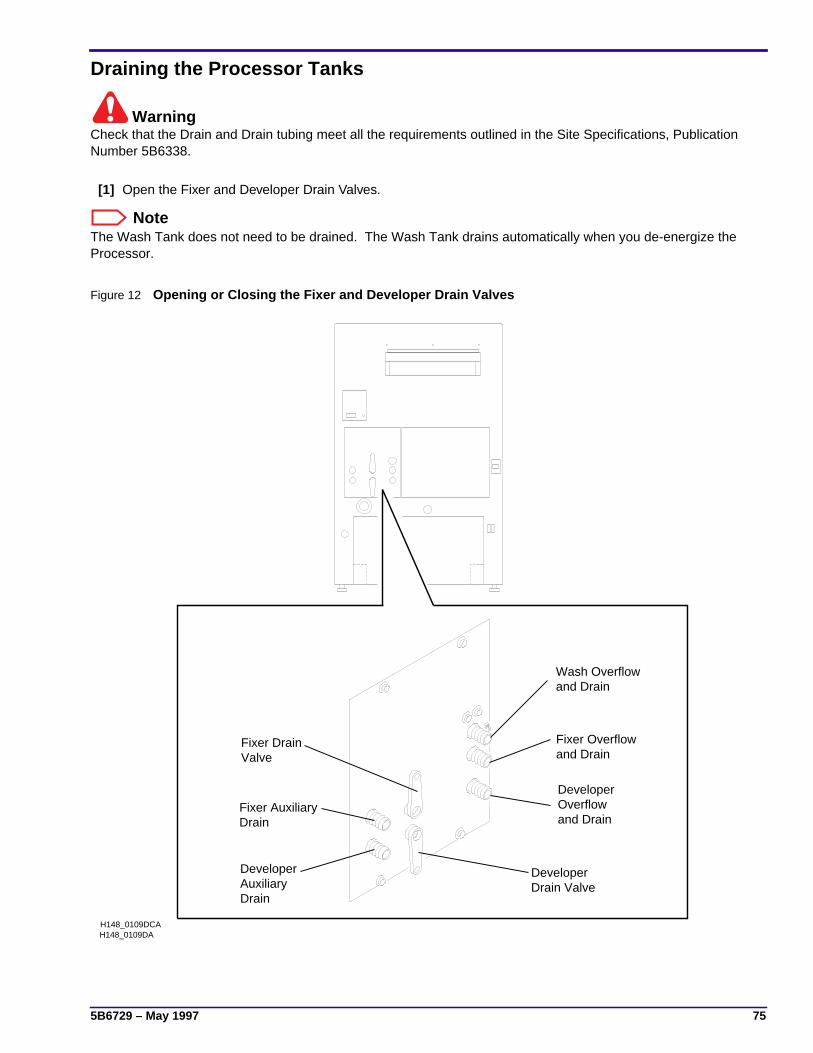
5B6729 – May 1997 75
Draining the Processor Tanks
WarningCheck that the Drain and Drain tubing meet all the requirements outlined in the Site Specifications, PublicationNumber 5B6338.
[1] Open the Fixer and Developer Drain Valves.
NoteThe Wash Tank does not need to be drained. The Wash Tank drains automatically when you de-energize theProcessor.
Figure 12 Opening or Closing the Fixer and Developer Drain Valves
H148_0109DA
Drain ValveDeveloper
and DrainFixer Overflow
DrainAuxiliaryDeveloper
DrainFixer Auxiliary
ValveFixer Drain
Wash Overflowand Drain
DeveloperOverflowand Drain
H148_0109DCA

OPERATORS MANUAL
76 May 1997 – 5B6729

READYSTD
DRYER TEMP
SLEEP SELECT CYCLE
MORE GO TO SETUP
(WALK UP MENU)
FILM IN PROCESSSTD
DRYERTEMP
MORE
STD
STD
STD
STDPRESS BUTTON TO SELECT
INFO SETUP OPTIONS DONE/RETURN
CHEM/CYCLE
MORE DONE/RETURN
15:06 12/25/96
DONE/RETURN
96.1 = CURRENT FIXER TEMPERATUREDONE/
RETURN
*MIXER LEVELS FOR 5000 RA/ICM ONLY
DONE/RETURN
*MIXERLEVELS
TIME/DATE
DISPLAYFIX TEMP
UNITS ARE ENGLISH
ENGLISH METRIC DONE/RETURN
PRESS BUTTON TO SELECT
REPLENMODE
DAILYSTARTUP
DISPLAYUNITS
MORE DONE/RETURN
TUESDAY DAILY STARTUP ON
PREVDAY
NEXTDAY
ON OFF DONE/RETURN
REPLENISHMENT MODE IS AUTOMATIC
AUTO FLOODED TANKFILL
DISABLEREPLEN
DONE/RETURN
PRESS BUTTON TO SELECT
USAGE DIAG SWVERSION
MORE DONE/RETURN
PRESS BUTTON TO SELECT
DEVUSAGE
FIXERUSAGE
FILMUSAGE
SETUPGROUPS
DONE/RETURN
12345 GAL 10/21/96
CLEARUSAGE
USAGERATE
DONE/RETURN
85 ML = DEV USAGE/SHEET
DONE/RETURN
34567 L 05/13/96
CLEARUSAGE
USAGERATE
DONE/RETURN
254 ML = FIXER USAGE/SHEET
DONE/RETURN
99999 = 6.5 X 8.5 IN
CLEARUSAGE
SHEETCOUNT
DONE/RETURN
9999999 = SHEET COUNT
DONE/RETURN
14 X 17 IN = GROUP1
SHOWMETRIC
SHOWU.S.
NEXTGROUP
DONE/RETURN
5 X 7 IN = GROUP2
SHOWMETRIC
SHOWU.S.
NEWGROUP
DONE/RETURN
100/105 MM = GROUP3
SHOWMETRIC
SHOWU.S.
NEXTGROUP
DONE/RETURN
120 F = DRYER SETPOINT
To Page 78
To Page 79
12/28/96
ACCY
STD K/RA120 F = DRYER SETPOINT
DONE/RETURN
1 2 3 4 CANCELREQUEST
PRESS BUTTON TO SELECTENTER ACCESS CODE OR
CANCEL REQUEST
<
<
<
<
<
<
Menu Flowchart for the 5000 RA Processor
RAPIDCYCLE
STDCYCLE
DONE/RETURN
IF RA MODE IS SELECTED, THE ÒSELECT CYCLEÓ BUTTON WILL BE BLANKED
EXTDCYCLE
DONE/RETURN
PRESS BUTTON TO SELECT
RAPIDCYCLE
K/RA
SELECTED CHEMISTRY IS RP
RP RA DONE/RETURN
PRESS BUTTON TO SELECT
K/RACYCLE
STDCYCLE
EXTDCYCLE
DONE/RETURN
STD K/RA
DONE/RETURN

PRESS BUTTON TO SELECT
PROCESS CLOCK AUTOSTARTUP
PUMPCALIB
DONE/RETURN
STDPRESS BUTTON TO SELECT
TEMP REPLENVOLUME
SPEED DONE/RETURN
STD
STD
STD
PRESS BUTTON TO SELECT
DEVTEMP
FIXTEMP
DONE/RETURN
95.0 F = FIXER SETPOINT
DEFAULTSETTING
CANCELREQUEST
DONE/RETURN
95.0 F = DEVELOPER SETPOINT
DEFAULTSETTING
CANCELREQUEST
DONE/RETURN
STD
STD
STDPRESS BUTTON TO SELECT
60 ML = DEVELOPER REPLENISHMENT VOLUME
DEFAULTSETTING
CANCELREQUEST
DONE/RETURN
60 ML = FIXER REPLENISHMENT VOLUME
DEFAULTSETTING
CANCELREQUEST
DONE/RETURN
STD45 IN/MIN = SPEED SETPOINT
DEFAULTSETTING
CANCELREQUEST
DONE/RETURN
DEV REPVOLUME
FIX REPVOLUME
DONE/RETURN
PRESS BUTTON TO SELECT
SETTIME
SETDATE
TIMEFORMAT
DATEFORMAT
DONE/RETURN
12:30 AM = CURRENT TIME
HOUR HOUR MINUTE MINUTEDONE/
RETURN
PRESS BUTTON TO SELECT
DONE/RETURN
SETDATE
SETYEAR
YEAR YEARDONE/
RETURN
1996 = CURRENT YEAR
10-31 = CURRENT DATE
MONTH MONTH DAY DAYDONE/
RETURN
M-D-Y = DATE DISPLAY FORMAT
M-D-YFORMAT
D-M-YFORMAT
Y-M-DFORMAT
DONE/RETURN
12 HOUR = TIME DISPLAY FORMAT
12 HOURFORMAT
24 HOURFORMAT
DONE/RETURN
AUTO STARTUP IS ON
SETTIMERS
ON OFF DONE/RETURN
PRESS BUTTON TO SETUP FOR MONDAY
TIMER1CONTROL
TIMER2CONTROL
COPYPREV
NEXTDAY
DONE/RETURN
SETUP TIMER FOR MONDAY
ONTIME
OFFTIME
ON OFF DONE/RETURN
12:30 AM = CURRENT ON TIME
HOUR HOUR MINUTE MINUTEDONE/
RETURN
* If timer1 or timer 2 is off, the "ON TIME" and "OFF TIME" buttons will be blank.
PRESS BUTTON TO SELECT
DEVCAL
FIXCAL
DONE/RETURN
PRESS REPLEN CAL SWITCH TO START CAL
UPDATECAL VOL
DONE/RETURN
60 ML = MEASURED FIXER VOLUME
DONE/RETURN
60ML = MEASURED DEVELOPER VOLUME
DONE/RETURN
<
<
<
<
<
<
<
<
<
<
<
<
<
<
<
<
<
<
<
<
<
<
<
<
<
<
<
<
OPERATOR MANUAL
PRESS BUTTON TO SELECT
RAPIDCYCLE
PRESS BUTTON TO SELECT
RP RA DONE/RETURN
PRESS BUTTON TO SELECT
K/RACYCLE
STDCYCLE
EXTCYCLE
DONE/RETURN
DONE/RETURN

TEMPERATURE LOCKOUT IS ON
ON OFF DONE/RETURN
ACCESS IS CURRENTLY ALLOWED
LIMITACCESS
ALLOWACCESS
DONE/RETURN
PRESS BUTTON TO SELECT
ACCESSCODE
USERACCESS
TEMPLOCK
MORE DONE/RETURN
ENTER NEW ACCESS CODE
1 2 3 4 CANCELREQUEST
STANDBY MODE IS INTERVAL
INTER CONT DONE/RETURN
RECEPTACLE MODE IS SAFELIGHT
SAFE ACCY DONE/RETURN
PRESS BUTTON TO SELECT
STANDBYMODE
ROLLERJOG
COOLDOWN
MORE DONE/RETURN
ROLLER JOG IS ON
ON OFF DONE/RETURN
PRESS BUTTON TO SELECT
RECEPTMODE
ALARMVOLUME
MORE DONE/RETURN
10 = CURRENT ALARM VOLUME
DONE/RETURN
PRESS BUTTON TO SELECT
LANG MOREDONE/
RETURN
LANGUAGE IS ENGLISH
ENGLISH FRENCH GERMAN MORE DONE/RETURN
LANGUAGE IS ENGLISH
SPANISH SWEDISH NORWEG MORE DONE/RETURN
LANGUAGE IS ENGLISH
DANISH DUTCH ITALIAN MOREDONE/
RETURN
LANGUAGE IS ENGLISH
PORTU FINNISH JAPAN MOREDONE/
RETURN
COOL DOWN IS ON
ON OFF DONE/RETURN
to first option screen
<
<

OPERATORS MANUAL
80 May 1997 – 5B6729
This page is intentionally blank.

5B6729 – May 1997 81
Preventive Maintenance
Weekly
ImportantReliable operation of the Processor requires that you clean, adjust, and lubricate all parts correctly. More frequentmaintenance may be necessary because of site conditions or actual usage. The following guidelines are forProcessors installed according to the Site Specifications. For monthly and quarterly maintenance, contact yourtrained service provider.
WarningWear rubber gloves, safety glasses, and protective clothing when doing any daily maintenance procedure. Reportany change in the operating condition of the Processor to your service provider.
[1] Move the main Circuit Breaker CB1 on the Processor to the “OFF” position and the wall power switch to the“OFF” position.
[2] Turn off the water supply.
[3] Remove the Top Cover.
[4] Disconnect the Crossover Fill Trough.
Caution
• Handle these assemblies carefully to prevent changing the alignment. Do not wash the Racks and Crossoverswith water hotter than 44°C (110°F). Do not clean the Racks, Crossovers, or Squeegee Rollers using abrasivematerials or alcohol.
• To prevent fixer or developer contamination when you remove the Fixer or Developer Rack, place the SplashGuard between the developer and fixer Tanks. Use the Rack Drip Tray when you remove or install any of theRacks.
Figure 13 Using the Splash Guard and Drip Tray
H108_0035AAH108_0035ACD
TrayDripRack
GuardSplash
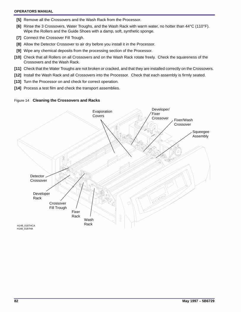
OPERATORS MANUAL
82 May 1997 – 5B6729
[5] Remove all the Crossovers and the Wash Rack from the Processor.
[6] Rinse the 3 Crossovers, Water Troughs, and the Wash Rack with warm water, no hotter than 44°C (110°F).Wipe the Rollers and the Guide Shoes with a damp, soft, synthetic sponge.
[7] Connect the Crossover Fill Trough.
[8] Allow the Detector Crossover to air dry before you install it in the Processor.
[9] Wipe any chemical deposits from the processing section of the Processor.
[10] Check that all Rollers on all Crossovers and on the Wash Rack rotate freely. Check the squareness of theCrossovers and the Wash Rack.
[11] Check that the Water Troughs are not broken or cracked, and that they are installed correctly on the Crossovers.
[12] Install the Wash Rack and all Crossovers into the Processor. Check that each assembly is firmly seated.
[13] Turn the Processor on and check for correct operation.
[14] Process a test film and check the transport assemblies.
Figure 14 Cleaning the Crossovers and Racks
FIXER
DEV
H148_0187HAH148_0187HCA
AssemblySqueegee
RackWash
CrossoverFixer/Wash
RackFixer
CrossoverFixerDeveloper/
RackDeveloper
CrossoverDetector
CoversEvaporation
Fill TroughCrossover
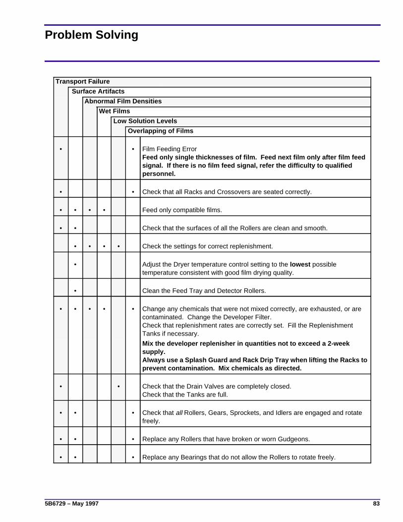
5B6729 – May 1997 83
Problem Solving
Transport Failure
Surface Artifacts
Abnormal Film Densities
Wet Films
Low Solution Levels
Overlapping of Films
• • Film Feeding ErrorFeed only single thicknesses of film. Feed next film only after film feedsignal. If there is no film feed signal, refer the difficulty to qualifiedpersonnel.
• • Check that all Racks and Crossovers are seated correctly.
• • • • Feed only compatible films.
• • Check that the surfaces of all the Rollers are clean and smooth.
• • • • Check the settings for correct replenishment.
• Adjust the Dryer temperature control setting to the lowest possibletemperature consistent with good film drying quality.
• Clean the Feed Tray and Detector Rollers.
• • • • • Change any chemicals that were not mixed correctly, are exhausted, or arecontaminated. Change the Developer Filter.Check that replenishment rates are correctly set. Fill the ReplenishmentTanks if necessary.
Mix the developer replenisher in quantities not to exceed a 2-weeksupply.Alway s use a Splas h Guard and Rack Drip Tray when liftin g the Racks toprevent contamination. Mix chemicals as directed.
• • Check that the Drain Valves are completely closed.Check that the Tanks are full.
• • • Check that all Rollers, Gears, Sprockets, and Idlers are engaged and rotatefreely.
• • • Replace any Rollers that have broken or worn Gudgeons.
• • • Replace any Bearings that do not allow the Rollers to rotate freely.
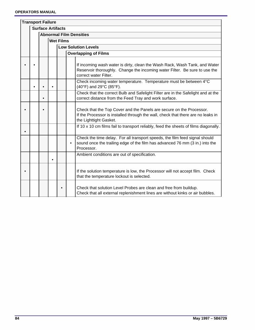
OPERATORS MANUAL
84 May 1997 – 5B6729
• • If incoming wash water is dirty, clean the Wash Rack, Wash Tank, and WaterReservoir thoroughly. Change the incoming water Filter. Be sure to use thecorrect water Filter.
• • •Check incoming water temperature. Temperature must be between 4°C(40°F) and 29°C (85°F).
•Check that the correct Bulb and Safelight Filter are in the Safelight and at thecorrect distance from the Feed Tray and work surface.
• • Check that the Top Cover and the Panels are secure on the Processor.If the Processor is installed through the wall, check that there are no leaks inthe Lighttight Gasket.
•If 10 x 10 cm films fail to transport reliably, feed the sheets of films diagonally.
•Check the time delay. For all transport speeds, the film feed signal shouldsound once the trailing edge of the film has advanced 76 mm (3 in.) into theProcessor.
•Ambient conditions are out of specification.
• If the solution temperature is low, the Processor will not accept film. Checkthat the temperature lockout is selected.
• Check that solution Level Probes are clean and free from buildup.Check that all external replenishment lines are without kinks or air bubbles.
Transport Failure
Surface Artifacts
Abnormal Film Densities
Wet Films
Low Solution Levels
Overlapping of Films
5B6729 – May 1997 85
Warranty
Kodak warrants this Kodak X-Omat 5000 RA Processor to function correctly for one year from the dateof initial installation, when installed within one year from date of shipment.
Warranty Repair CoverageIf this equipment does not function correctly during the warranty period, the dealer (for Kodak X-Omat5000 RA Processors) who sold the equipment will provide or arrange for repair of the equipment duringthe dealer’s normal working hours. Such repair service will include any adjustments and/orreplacement of parts required to maintain your equipment in good working order.
How To Obtain ServiceShould the equipment require service, refer to the sales contract for details on whom to call for service,or contact the dealer (for Kodak X-Omat 5000 RA Processors) who sold the equipment.
LimitationsWarranty service is limited to the contiguous United States, the island of Oahu in Hawaii, and certainareas of Alaska.
This warranty does not cover —• circumstances beyond the control of Kodak
• misuse
• abuse
• attachments
• accessories
• alterations not marketed by Kodak (including service or parts to correct problems resulting from theuse of such attachments, accessories, or alterations)
• failure to follow the operating instructions recommended by Kodak
• supply items
Kodak makes no other warranties, express or implied, for this equipment.
Repair without charge is the only obligation of both Kodak and the dealer under this warranty.Kodak will not be responsible for any consequential or incidental damages resulting from thesale, use, or improper functioning of this equipment, even if loss or damage is caused by thenegligence or other fault of Kodak.
Such damages for which Kodak will not be responsible, include, but are not limited to, loss of revenueor profit, downtime costs, loss of use of the equipment, cost of any substitute equipment, facilities orservices or claims of your customers for such damages.
This limitation of liability will not apply to claims for injury to persons or damage to property caused bythe sole negligence or fault of Kodak or by persons under its direction or control.

OPERATORS MANUAL
86 May 1997 – 5B6729
This page is intentionally blank.

5B6729 – May 1997 87
Publication History
Date Pub. No. ECO No. Affected Pages File Name Notes
October 1995 5B6729 2649-029 All om3425_1_029.doc First printing.
January 1996 5B6729 2649-062 47, 87, 88, & covers. om3425_1_062.doc Graphic Unification plusminor edits.
May 1997 5B6729 2649-142 5, 7, 8, 10, 18-23, 36,43, 46-49, 58, 77-84
om3425_1_142.doc Updated manual to reflectnew software and fixed afew typos.
January 1998 5B6729 2649-142 All om342500.fm First CD-ROM printing.Content is identical to May1997 version; formattingmay vary from printversion.

om342500.fm
Printed In USA
HEALTH IMAGING
EASTMAN KODAK COMPANY ● ROCHESTER, N.Y. 14650
Kodak and X-Omat are trademarks.