
OPERATOR MANUAL - Frank's Hospital Workshop€¦ · 150830-442 Operator Manual Listing of ......
38
OPERATOR MANUAL ASC 2000™ Ambulatory Surgical Table (08/10/11) P150830-442
Transcript of OPERATOR MANUAL - Frank's Hospital Workshop€¦ · 150830-442 Operator Manual Listing of ......

OPERATOR MANUAL
ASC 2000™Ambulatory Surgical Table
(08/10/11) P150830-442

iTable of Contents Operator Manual 150830-442
A WORD FROM STERIS CORPORATION
IMPORTANT: Read this entire manual before attempting to install oroperate your ASC 2000™ Ambulatory Surgical Table. Ensure all appro-priate personnel understand the contents of this manual.
This Operating Manual contains important information on proper use andmaintenance of the ASC 2000 Ambulatory Surgical Table. All personnelinvolved in the use and maintenance of this equipment must carefullyreview and comply with the warnings, cautions, and instructions con-tained in this manual. These instructions are important to protect the healthand safety of personnel operating the table and should be retained in aconveniently accessible area for quick reference.
Complete instructions for uncrating have been furnished. If missing, contactSTERIS for a replacement copy, giving the serial, equipment, and modelnumbers of the unit.
STERIS carries a complete line of accessories for use with this table. STERISrepresentatives will gladly review these with you.
A listing of the Safety Precautions to be observed when operating andservicing this equipment can be found in Section 1 of this manual. Do notoperate or service the equipment until you have become familiar with thisinformation.
Any alteration of this equipment not authorized or performed by STERISEngineering Service which could affect operation will void the warranty,could adversely affect proper table functioning and could violate federal,state, and local regulations.
The ASC 2000 Ambulatory Surgical Table is primarily designed for ambula-tory surgical care facilities.
A thorough preventive maintenance program is essential for safe and properunit operation. This manual contains maintenance schedules and proce-dures which should be followed for satisfactory equipment performance.Comprehensive instructions for monthly, quarterly, and semi-annual preven-tive maintenance can be found in the Maintenance Manual, P764331-449(available from STERIS).
Only STERIS-trained personnel should attempt to perform maintenance onthe ASC 2000 Ambulatory Surgical Table to avoid personal injury or damageto the product.
You are encouraged to contact STERIS concerning our comprehensive Preven-tive Maintenance Agreement. Under the terms of this agreement, preventivemaintenance, adjustments, and replacement of worn parts are done on ascheduled basis to help assure optimal equipment performance and help avoiduntimely or costly interruptions. STERIS maintains a global staff of well equipped,factory-trained technicians to provide these services, as well as expert repairservices. Please contact STERIS for details.
NOTE: A patient grounding post/potential equalization terminal (male connec-tor, DIN 42801) is provided. The female connector for patient grounding is notfurnished by STERIS.
©2011, STERIS Corporation. All rights reserved. Printed in U.S.A.
Advisory
Service Information
Indications for Use

ii150830-442 Operator Manual Table of Contents
Distributed by:STERIS Corporation2720 Gunter Park EastMontgomery, AL 36109 • USATEL: 334 277 6660FAX: 334 271 5450www.steris.com
Class 1 EquipmentType B Equipment
Splash-Proof Equipment (enclosed equipment protected against splashingwater, IPX4)
Equipment not suitable for use in the presence of a flammableanesthetic mixture with air or oxygen or nitrous oxide.
Suitable for continuous operation with short-time loading (15% duty cycle).
Manufactured for STERIS by MEDILAND of Taiwan.
EC Authorized Representative
STERIS Ltd.Chancery House190 Waterside RoadHamilton Industrial ParkLeicesterLE5 1QZUNITED KINGDOM
The base language of this document isENGLISH. Any translations must be
made from the base language document.
STERIS Corporation, Montgomery, Alabama is anISO 13485 certified facility.
iiiTable of Contents Operator Manual 150830-442
TABLE OF CONTENTS
Section Title Page
A WORD FROM STERIS CORPORATION ............................................. i
1 LISTING OF PRECAUTIONS AND SAFETY LABELS ......................... 1-1
1.1 Safety Label on the Table ............................................................................................ 1-4
1.2 Symbols on the Table................................................................................................... 1-5
2 IMPORTANT USER INFORMATION.................................................... 2-1
2.1 Pinch Point Warnings ................................................................................................... 2-1
2.2 Patient Positioning and Weight Limitation .................................................................... 2-3
2.3 Patient Safety Straps ................................................................................................... 2-3
2.4 Auxiliary Control Switches ........................................................................................... 2-4
2.5 General Description ..................................................................................................... 2-5
2.6 Technical Specifications .............................................................................................. 2-6
2.6.1 Overall Size ........................................................................................................... 2-6
2.6.2 Ranges of Motion .................................................................................................. 2-6
2.6.3 Weight ................................................................................................................... 2-6
2.6.4 Power Requirements ............................................................................................. 2-6
2.6.5 Environmental Conditions ..................................................................................... 2-6
2.6.6 Image Amplification Coverage.............................................................................. 2-6
3 INSTALLATION INSTRUCTIONS ....................................................... 3-1
4 OPERATING INSTRUCTIONS ............................................................ 4-1
4.1 Operating the Table ..................................................................................................... 4-1
4.2 Weight Capacity .......................................................................................................... 4-2
4.3 Hand Control ................................................................................................................ 4-2
4.3.1 Hand Control Function Buttons Description ......................................................... 4-2
4.3.2 Hand Control LEDs Description ........................................................................... 4-5
4.4 Auxiliary Control System .............................................................................................. 4-5
4.5 Headrest Operation ..................................................................................................... 4-6
4.6 Leg Section Operation ................................................................................................. 4-6
4.7 Table Pads ................................................................................................................... 4-7

iv150830-442 Operator Manual Table of Contents
TABLE OF CONTENTS (Cont'd)
Section Title Page
4.8 Accessories/Side Rails ................................................................................................ 4-7
4.8.1 Permanently Attached Side Rails ......................................................................... 4-7
4.8.2 Drain Pan ............................................................................................................. 4-8
5 ROUTINE MAINTENANCE ................................................................. 5-1
5.1 Read Before Performing Routine Maintenance ........................................................... 5-1
5.2 Cleaning the Table ....................................................................................................... 5-1
5.2.1 General ................................................................................................................ 5-2
5.2.2 After Each Usage ................................................................................................. 5-2
5.2.3 End-Of-Day Cleaning Procedure ......................................................................... 5-3
5.2.4 Weekly Cleaning Procedure ................................................................................. 5-3
5.3 Bi-Weekly Maintenance ............................................................................................... 5-3
5.4 Monthly Maintenance................................................................................................... 5-3
5.5 Battery Charging Procedure ........................................................................................ 5-4
5.6 Preventive Maintenance .............................................................................................. 5-5
5.7 Replacement Parts ...................................................................................................... 5-6
6 TROUBLESHOOTING ......................................................................... 6-1
7 DISPOSAL HAZARDS ......................................................................... 7-1
1-1Listing of Precautions and Safety Labels Operator Manual 150830-442
The following list of Safety Precautions must be observed when operating and servicing the ASC 2000™ AmbulatorySurgical Table. WARNINGS indicate the potential for danger to personnel, and CAUTIONS indicate the potential fordamage to equipment. These precautions are repeated (in whole or in part), where applicable, throughout the manual.It is important to review these Safety Precautions before operating the table.
WARNING – PINCHING HAZARD:Pinch points are created during tabletop articulation. Carefully review illustrations in Figures 2-1 through 2-3before operating the table.
To avoid serious injury, keep limbs, fingers, and other body areas clear of all pinch points when positioning thetable.
When manually positioning table sections, stay clear of potential pinching hazards.
WARNING – TIPPING HAZARD:
Do not place patient on the table unless floor locks are engaged.
Do not release floor locks while patient is on table.
Do not use this table for patients exceeding the 400-lb (181-kg) limit.
WARNING – EXPLOSION HAZARD:
Table must not be used in the presence of flammable anesthetics.
WARNING – TRIPPING HAZARD:Route the power cord to the receptacle in a position so that it will not be tripped over by personnel in the area.
WARNING – PERSONAL INJURY HAZARD:Failure to keep the patient properly secured with the patient safety straps at all times could result in death orserious injury to the patient and the operating room staff.
The floor locks must be engaged at all times when a patient is on the table. Failure to lock the floor locks beforeplacing a patient on the table or disengaging the floor locks while a patient is on the table could result in the tablerolling unexpectedly during the procedure.
The table is not intended for patient transport. Transporting a patient on the table could result in accidental deathor serious personal injury to the patient and/or the operating room staff.
Keep hands and feet clear of the unloading platform and the table base when unloading the table. Seriouspersonal injury could result.
Section 4.1, Steps 1-5 in "Operating the Table" must be executed before patient transfer to the table. Executionof Steps 1-5 with the patient on the table could result in death or serious injury to both the patient and the operatingroom staff.
Healthcare professionals must ensure that patients are positioned and monitored so as to prevent compromisingrespiration, nerve pathways, or circulation.
LISTING OF PRECAUTIONS AND SAFETY LABELS 1
Continued ...
1-2150830-442 Operator Manual Listing of Precautions and Safety Labels
WARNING – PERSONAL INJURY HAZARD (Cont'd):When installing any table accessory, check for correct attachment and tighten securely (if appropriate). Do notuse a worn or damaged accessory. Check installation before using any accessory.
Unanticipated table movement could cause patient injury. Patient must be secured to the table in accordancewith recommended positioning practices.
When cleaning/disinfecting table, do not use phenolics, which may cause patient skin burns if inadequately rinsed off, oralcohol, which does not have sufficient cleaning/disinfection properties.
The Table Leg Sections are designed to support the patient legs. Do not put body weight on the Leg Sections.
If the integrity of the external protective earth conductor installation or arrangement is in doubt, operate the tablefrom its internal power source.
WARNING – INSTABILITY HAZARD:Possible patient or user injury, as well as table or accessory failure, may result from using STERIS tableaccessories for other than their stated purpose – or from using, on STERIS tables, accessories manufactured andsold by other companies.
WARNING – PINCHING AND TIPPING HAZARD:Patient injury may result if the operator of this table is not completely familiar with the controls for patient positioningand table operation.
WARNING – PERSONAL INJURY AND/OR EQUIPMENT DAMAGE HAZARD:
Table is factory set to operate at a certain voltage. Use of any other power supply could result in serious personalinjury or table damage.
Use of this table in the presence of flammable anesthetics could result in serious personal injury or table damage.
Placing a patient whose weight exceeds the 400-lb (181-kg) weight limit could result in death or serious injuryto the patient and the operating room staff, and serious equipment damage.
Failure to perform periodic inspections of the table could result in serious personal injury or table damage.
Repairs and adjustments to this equipment must be made only by STERIS or STERIS-trained service personnel.Nonroutine maintenance performed by unqualified personnel or installation of unauthorized parts could causepersonal injury, invalidate the warranty, or result in costly damage. Contact STERIS regarding service options.
Regularly scheduled preventive maintenance is essential for safe and reliable operation of the equipment.Contact STERIS to schedule preventive maintenance.
The X-Ray Cassette Top accessory back section spans both the upper and lower table back sections. Failure to keepthe table upper and lower back sections parallel with each other can cause equipment damage and injury.
WARNING – INFECTION HAZARD:To protect against aerosols being reflected from potentially contaminated surfaces, wear rubber or plasticgloves, masks and eye protection, and follow OSHA blood-borne pathogens standards when cleaning.
WARNING – DISPOSAL HAZARD:This product contains materials which may require disposal through appropriately licensed and permittedhazardous waste management firms.

1-3Listing of Precautions and Safety Labels Operator Manual 150830-442
CAUTION – POSSIBLE EQUIPMENT DAMAGE:Failure to keep all personnel and equipment clear of the table before actuating any inertia-driven or power-drivenmovement could result in table damage.
When moving the table to or from point of use, roll it carefully at moderate speed and only over smooth floors.Maximum floor clearance is 1/4" (6.4 mm). Avoid door and elevator jambs, and obstructions greater than 1/4" (6.4mm). If necessary, lift table over obstructions, onto trucks, etc. Lift table evenly and only by the table base. DONOT transport articles (including accessories) on top of the table, and DO NOT use a forklift to move theuncrated table.
Hang the Hand Control from side rail of the table when not in use, to avoid possible damage to the control.
When cleaning/disinfecting table, do not use phenolics, which may cause patient skin burns if inadequatelyrinsed off, or alcohol, which does not have sufficient cleaning/disinfection properties.
When cleaning/disinfecting table, thoroughly read the cleaning fluid directions for use and follow all directionsand cautions as shown.
Do not spray cleaning fluid into electric receptacles and avoid spraying directly on emergency backup buttonsor into clearance space. Spray or drippage may settle onto electric circuits inside table causing corrosion andloss of function.
Cleaning procedures requiring articulation of the table should be performed only by persons familiar with tableoperation.
After performing cleaning procedures, ensure pads and tops are completely dry before reinstalling.
Route the hand control cord clear of any pinch points where cord could be damaged.
Use of incorrect hydraulic oil may severely damage the table and/or cause malfunction. Contact STERIS forproper hydraulic oil.
After performing cleaning procedures, ensure pads and X-ray tops are completely dry before reinstalling.Moisture trapped between pads and X-ray tops may contribute to equipment damage, such as X-ray topwarpage.

1-4150830-442 Operator Manual Listing of Precautions and Safety Labels
1.1 Safety Labelon the Table
Following is the safety label on the ASC 2000 Ambulatory Surgical Table.

1-5Listing of Precautions and Safety Labels Operator Manual 150830-442
1.2 Symbolson the Table
Following is a key to symbols on the ASC 2000 Ambulatory Surgical Table.
Symbol Definition
Type B Equipment
Protective Earth Ground
Equipotentiality
Electric Shock Hazard
Control Power ON
Control Power OFF
Powered By AC
Attention, Consult Manual for Further Instructions
A Amperage Rating of the Unit
V Voltage Rating of the Unit
~ Alternating Current
Hz Frequency of the Unit
W Power Rating
SNSNSNSNSN Serial Number of the Unit
- OR -- OR -- OR -- OR -- OR -

2-1Important User Information Operator Manual 150830-442
2IMPORTANT USER INFORMATION
When inertia-driven or power-driven table parts close (especially duringextreme tabletop articulation), pinch-point hazards exist (see Figs. 2-1 through2-3). All personnel involved in tabletop positioning should examine and beaware of these points before operating the table.
Pinch points shown (circled) in Figure 2-1:
1. Between Leg Section and Base Cover or Column Cover.
2. Between Headrest and Base Cover.
3. Between Leg Section and Seat Section.
4. Between Lower Back Section and Yoke.
5. Between Headrest and Floor.
2.1 Pinch PointWarnings
WARNING – PINCHING HAZ-ARD:
• Pinch points are createdduring tabletop articula-tion. Carefully review theillustrations in Figures 2-1through 2-3 before operat-ing the table.
• To avoid serious injury,keep limbs, fingers, andother body areas clear ofall pinch points when po-sitioning the table.
CAUTION – POSSIBLEEQUIPMENT DAMAGE: Fail-ure to keep all personnel andequipment clear of the tablebefore actuating any iner-tia-driven or power-drivenmovement could result intable damage. Figure 2-1. Pinch Points
Pinch points shown (circled) in Figure 2-2:
1. Between Thumbscrew of Seat Section and Yoke Cap.
2. Between Leg Section and Floor.
3. Between Leg Section and Base Cover.
4. Between Seat Section and Yoke Cap.
Figure 2-2. Pinch Points
12
3
52
4
1
23
4

2-2150830-442 Operator Manual Important User Information
Pinch points shown (circled) in Figure 2-3:
1. Between Headrest and Upper Back Section.
2. Between Upper Back Section and Lower Back Section.
3. Between Lower Back Section and Seat Section.
4. Between Upper Back Plate and Lower Back Plate.
5. Between Lower Back Plate and Seat Plate.
6. Between Lock Pedal and Base Cover or Between Foot Pedal and BaseCover.
Figure 2-3. Pinch Points
4 5
2 3
6
1

2-3Important User Information Operator Manual 150830-442
2.2 PatientPositioning and
Weight Limitation
NOTE: Accessories may have a specified weight limitation that is less than thatof the table. Do not exceed the lowest weight limit, table or accessory.
The table is designed to safely support a 400-lb (181-kg) patient. Do notexceed the maximum patient weight.
NOTE: When positioning the patient on the table, note the following:
1) Always check patient stability when patient is positioned.
2) Do not place patient on the table unless floor locks are engaged.
3) Do not release floor locks while patient is on table.
4) Do not attempt to move table while patient is on it.
5) Use extreme care when transferring patients to or from table.
6) Ensure all accessories are properly installed and secured.
7) Check for and eliminate harmful patient pressure points once patient ispositioned.
8) Have a qualified medical professional monitor patient during surgery for allpossible patient positioning hazards.
9) Do not place patient weight on the Leg Sections. Leg Sections were designedto support leg weight, not body weight.
2.3 Patient SafetyStraps
All patients must be restrained for proper safety regardless of the length or typeof procedure.
Adjust the patient safety straps such that they restrain the patient according tocurrently accepted patient restraining practices, keeping in mind thetrendelenburg/reverse trendelenburg, back, lateral tilt, and height adjustment.
WARNING – PERSONALINJURY HAZARD: Failure tokeep the patient properly se-cured with the patient safetystraps at all times could re-sult in death or serious injuryto the patient and the operat-ing room staff.
WARNING – TIPPING HAZ-ARD:
• Do not place patient onthe table unless floor locksare engaged.
• Do not release floor lockswhile patient is on table.
• Do not use this table forpatients exceeding the400-lb (181-kg) limit.
WARNING - PERSONALINJURY HAZARD: Healthcareprofessionals must ensurethat patients are positionedand monitored so as to pre-vent compromising respira-tion, nerve pathways, or cir-culation.

2-4150830-442 Operator Manual Important User Information
Six Auxiliary Control Switches are located behind the cover plate on the frontof the ASC 2000™ Ambulatory Surgical Table base (see Figs. 2-4 and 3-1). TheAuxiliary Control Switches may be used the moment the Hand Control/Foot Control becomes lost or damaged; or, they may be used to discon-nect the battery.
For the Auxiliary Control Switches to function:
1. Aside from loss or damage of the Hand/Foot Control, the table must befunctioning normally.
2. The table must be receiving AC electrical current or the Battery Switch mustbe ON (and the batteries charged).
Auxiliary Control Switch descriptions:
1. Tabletop Articulation (if electric pump is operational): REV., TREND.,HEIGHT, SIDE TILT, LOWER BACK, and UPPER BACK.
2. The POWER TRIGGER switch activates the Auxiliary Control Switches. IfAuxiliary Controls are idle for more than 70 seconds, the system willautomatically turn off.
NOTE: The BATTERY SWITCH should always be positioned to ON for BatteryPower Operation and Battery Charging. To interrupt the Battery Power andisolate the battery from the Power System, toggle switch to OFF.
2.4 Auxiliary ControlSwitches
Figure 2-4. Auxiliary Control Switches
WARNING - PERSONALINJURY HAZARD:
• The floor locks must beengaged at all times whena patient is on the table.Failure to lock the floorlocks before placing a pa-tient on the table or disen-gaging the floor lockswhile a patient is on thetable could result in thetable rolling unexpectedlyduring the procedure.
• The table is not intendedfor patient transport.Transporting a patient onthe table could result inaccidental death or seri-ous personal injury to thepatient and/or the operat-ing room staff.

2-5Important User Information Operator Manual 150830-442
The ASC 2000 Ambulatory Surgical Table (see Fig. 2-5) is battery powered andspecifically designed to provide the complete patient positioning flexibilityrequired for modern ambulatory surgical care facilities. The ASC 2000 SurgicalTable features powered lateral tilt, trendelenburg/reverse trendelenburg, andadjustable height functions. This table is designed to safely function with a400 lb (181 kg) patient and is constructed of aluminum alloy, stainless steel,and other high quality materials.
The table accepts positioning commands from three sources:
1. A Hand Control (which includes “ON”, "OFF", "TREND.”, "REV.", “HEIGHTUP”, "HEIGHT DOWN", “TILT LEFT”, "TILT RIGHT", "LOWER BACK DOWN","LOWER BACK UP", "UPPER BACK DOWN" and "UPPER BACK UP". Referto Figure 4-2 of this document for control feature locations.
2. Auxiliary Control Switches. Refer to Figure 2-4 of this section of thedocument for control feature locations.
3. An optional physician-controlled Foot Control (which includesTrendelenburg Tilts, Lateral Tilts, and Height functions).
NOTE: The Headrest and Leg Sections are manually adjustable.
2.5 GeneralDescription
KEY:1. Headrest2. Upper Back Section3. Lower Back Section4. Seat Section5. Leg Section6. Table Top7. Side Rail8. Fixed Handle For Leg Section9. Pull Rod10. Lock Pedal11. Emergency Backup Switches12. Hand Control13. Thumbscrew For Head Section
Figure 2-5. ASC 2000 Table Components (Typical)

2-6150830-442 Operator Manual Important User Information
2.6.1 Overall Size
2.6.3 Weight
2.6.4 Power Requirements
2.6 TechnicalSpecifications
2.6.2 Ranges of Motion
22" wide x79" long x 27.5" to 41" high(547 mm wide x 2009 mm long x 699 to 1045 mm high)
Height: 27.5" to 41" (699 to 1045 mm)
Trendelenburg Range: 45° ±1°
Reverse Trendelenburg Range: 20° ±1°
Lateral Tilt Range: 20° ±1°
Lower Back Motion: UP: 75° ±1° DOWN: 15° ±1°
Upper Back Motion: UP: 40° ±1° DOWN: 55° ±1°
Head Motion (Manual): UP: 33° ±1° DOWN: 87° ±1°
Leg Motion (Manual): UP: 0° DOWN: 90° ±1°
(Swivel 90° toward outside)
485 lbs (220 kg)Maximum Patient Weight: 400 lbs (181 kg); Distributed as:• 30 lbs (14 kg) Maximum on Headrest• 90 lbs (41 kg) Maximum on Upper Back Section• 90 lbs (41 kg) Maximum on Lower Back Section• 86 lbs (39 kg) Maximum on Seat Section• 52 lbs (24 kg) Maximum on Each Leg Section
Line Power Input:
• 100-132 VAC, One-Phase, 50/60 Hz, 5.0 A
• 180-264 VAC, One-Phase, 50/60 Hz, 3.0 A
NOTE: Each table is shipped from the factory configured to the electricalrequirement specified on the factory order. If this electrical configuration needs tobe changed in the field,consult STERIS for the needed procedure and requiredmaterials.
Temperature: 32-122°F (0-50°C)
Relative Humidity: 20-80% RH
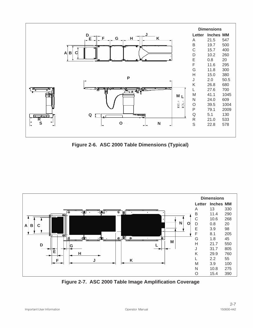
See Figure 2-7.
See Figure 2-6.
2.6.5 EnvironmentalConditions
2.6.6 Image AmplificationCoverage
2-7Important User Information Operator Manual 150830-442
Figure 2-6. ASC 2000 Table Dimensions (Typical)
Figure 2-7. ASC 2000 Table Image Amplification Coverage
C
D
EG
H
J
BA
L
K
M
N O
F
DimensionsLetter Inches MMA 13 330B 11.4 290C 10.6 268D 0.8 20E 3.9 98F 8.1 205G 1.8 45H 21.7 550J 31.7 805K 29.9 760L 2.2 55M 3.9 100N 10.8 275O 15.4 390
DimensionsLetter Inches MMA 21.5 547B 19.7 500C 15.7 400D 10.2 260E 0.8 20F 11.6 295G 11.8 300H 15.0 380J 2.0 50.5K 26.8 680L 27.6 700M 41.1 1045N 24.0 609O 39.5 1004P 79.1 2009Q 5.1 130R 21.0 533S 22.8 578NO
M L
HGFED
CBA
KJ
RS
Q
P
3-1Installation Instructions Operator Manual 150830-442
3INSTALLATION INSTRUCTIONS
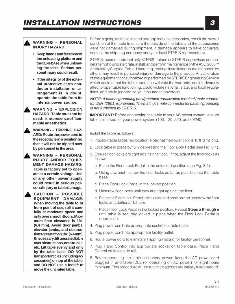
Before signing for the table and any applicable accessories, check the overallcondition of the table to ensure the outside of the table and the accessorieswere not damaged during shipment. If damage appears to have occurred,contact the shipping company and your local STERIS representative.
STERIS recommends that only STERIS-trained or STERIS-supervised person-nel attempt to uncrate/crate, install, and perform maintenance on the ASC 2000™Ambulatory Surgical Table. Uncrating, crating, installation, or maintenance byothers may result in personal injury or damage to the product. Any alterationof this equipment not authorized or performed by STERIS Engineering Servicewhich could affect the table operation will void the warranty, could adverselyaffect proper table functioning, could violate national, state, and local regula-tions, and could jeopardize your insurance coverage.
NOTE: A patient grounding post/potential equalization terminal (male connec-tor, DIN 42801) is provided. The mating female connector for patient groundingis not furnished by STERIS.
IMPORTANT: Before connecting the table to your AC power system, ensuretable is marked for your power system (100, 120, 220, or 230/240).
Install the table as follows:
1. Position table at desired location. Note that the power cord is 10 ft (3 m) long.
2. Lock table in place by fully depressing the Floor Lock Pedal (see Fig. 3-1).
3. Ensure floor locks are tight against the floor. If not, adjust the floor locks asfollows:
a. Place the Floor Lock Pedal in the unlocked position (see Fig. 3-1).
b. Using a wrench, screw the floor locks as far as possible into the tablebase.
c. Place Floor Lock Pedal in the locked position.
d. Unscrew floor locks until they are tight against the floor.
e. Place the Floor Lock Pedal in the unlocked position and unscrew the floorlocks an additional 1/2 turn.
f. Place Floor Lock Pedal in the locked position. Repeat Steps a through euntil table is securely locked in place when the Floor Lock Pedal isdepressed.
4. Plug power cord into appropriate socket on table base.
5. Plug power cord into appropriate facility outlet.
6. Route power cord to eliminate Tripping Hazard for facility personnel.
7. Plug Hand Control into appropriate socket on table base. Place HandControl on table side rail.
8. Before operating the table on battery power, keep the AC power cordplugged in and table IDLE (or operating on AC power) for eight hoursminimum. This procedure will ensure the batteries are initially fully charged.
WARNING – PERSONALINJURY HAZARD:
• Keep hands and feet clear ofthe unloading platform andthe table base when unload-ing the table. Serious per-sonal injury could result.
• If the integrity of the exter-nal protective earth con-ductor installation or ar-rangement is in doubt,operate the table from itsinternal power source.
WARNING – EXPLOSIONHAZARD: Table must not beused in the presence of flam-mable anesthetics.
WARNING – TRIPPING HAZ-ARD: Route the power cord tothe receptacle in a position sothat it will not be tripped overby personnel in the area.
WARNING – PERSONALINJURY AND/OR EQUIP-MENT DAMAGE HAZARD:Table is factory set to oper-ate at a certain voltage. Useof any other power supplycould result in serious per-sonal injury or table damage.
CAUTION – POSSIBLEEQUIPMENT DAMAGE:When moving the table to orfrom point of use, roll it care-fully at moderate speed andonly over smooth floors. Maxi-mum floor clearance is 1/4"(6.4 mm). Avoid door jambs,elevator jambs, and obstruc-tions greater than 1/4" (6.4 mm).If necessary, lift uncrated tableover obstructions, onto trucks,etc. Lift table evenly and onlyby the table base. DO NOTtransport articles (including ac-cessories) on top of the table,and DO NOT use a forklift tomove the uncrated table.

3-2150830-442 Operator Manual Installation Instructions
Figure 3-1. Floor Locks
9. Attach Headrest to table as follows:
NOTE: The thumbscrews located under the tabletop frame must be loosenedbefore installing or removing the headrest (see Figs. 2-5 and 3-2).
a. Loosen Headrest fastening thumbscrews located under tabletop.
b. Insert Headrest mounting bars into holes provided in end of Upper BackSection.
c. Securely tighten thumbscrews to fasten Headrest to Upper Back Sectionof the tabletop.
Figure 3-2. Attaching Headrest
Locked Position Unlocked Position
10. Install Leg Sections onto table as follows (see Fig. 3-3):
a. Insert each leg adapter (left and right) support pin into large hole in SeatSection. An upper alignment pin should be fully inserted in mating hole.
b. To hold adapters in place, tighten retaining knobs located under SeatSection (also see Fig. 4-4).
c. Place mounting post of appropriate Leg Section (left and right) into theadapter now mounted on the Seat Section.
d. Securely tighten Fixed Handle to fasten Leg Section to adapter mountedon Seat Section.
e. Repeat Steps c and d for remaining Leg Section.

3-3Installation Instructions Operator Manual 150830-442
Figure 3-3. Attaching Leg Sections
FixedHandle
SeatSection
SupportPin
WARNING – PERSONALINJURY HAZARD: The TableLeg Sections are designed tosupport the patient legs. Donot put body weight on theLeg Sections.
Left HandLeg Section
Right HandLeg Section
Right HandAdapter
FixedHandle
Left HandAdapter
RetainingKnob
SupportPin
AlignmentPin
AlignmentPin

4-1Operating Instructions Operator Manual 150830-442
4
4.1 Operating theTable
OPERATING INSTRUCTIONS
Operate the ASC 2000™ Ambulatory Surgical Table as follows:
1. Review Pinch Point Warnings as presented in Section 2.1 of this manual.
2. Verify that the power cord is plugged into both the facility outlet and the tablereceptacle and the Battery Switch is in the ON position.
3. For optimum performance, before attempting to operate the table, allow thetable to reach room temperature (see Fig. 4-1).
4. Ensure the floor locks are properly engaged (Floor Lock Pedal depressedin Lock position). If not, adjust per Step 3 of Section 3, InstallationInstructions, of this manual.
5. After referencing Section 4.3.1, Hand Control Function Buttons Description,position the tabletop to parallel with the earth plane.
NOTE: The ASC 2000 Table Headrest and Leg Sections must be manuallyadjusted.
6. Before placing the patient on the table, reference Section 4.2, WeightCapacity, in this manual. Assuming the weight of the patient does notexceed the indicated weight capacity for the table, transfer or positionpatient and ensure the patient is properly restrained (reference Sec-tion 2.3, Patient Safety Straps, in this manual).
NOTE: A patient grounding post/potential equalization terminal (male connec-tor, DIN 42801) is provided. The mating female connector for patient groundingis not furnished by STERIS.
WARNING – PERSONALINJURY HAZARD:
• Section 4.1, Steps 1 - 5 in"Operating the Table" mustbe executed before patienttransfer to the table. Ex-ecution of Steps 1 - 5 withthe patient on the tablecould result in injury to boththe patient and the operat-ing room staff.
• Healthcare professionalsmust ensure that patientsare positioned and moni-tored so as to preventcompromising respira-tion, nerve pathways, orcirculation.
• Unanticipated table move-ment could cause patientinjury. Patient must be se-cured to the table in ac-cordance with recom-mended positioning prac-tices.
• If the integrity of the exter-nal protective earth con-ductor installation or ar-rangement is in doubt,operate the table from itsinternal power source.
WARNING – PERSONALINJURY AND/OR EQUIP-MENT DAMAGE HAZARD:
• Table is factory set to op-erate at a certain voltage.Use of any other powersupply could result in se-rious personal injury ortable damage.
• Use of this table in thepresence of flammable an-esthetics could result inserious personal injury ortable damage.
Figure 4-1. ASC 2000 Ambulatory Surgical Table
4-2150830-442 Operator Manual Operating Instructions
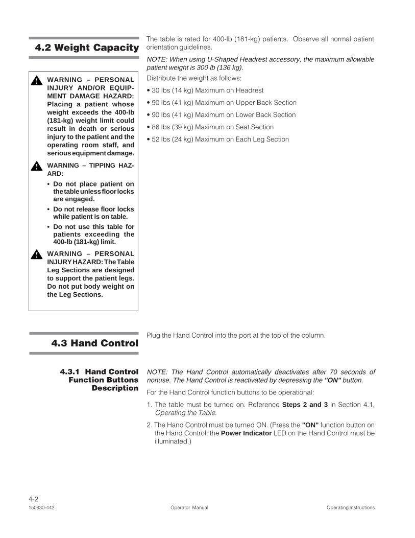
4.2 Weight Capacity
WARNING – PERSONALINJURY AND/OR EQUIP-MENT DAMAGE HAZARD:Placing a patient whoseweight exceeds the 400-lb(181-kg) weight limit couldresult in death or seriousinjury to the patient and theoperating room staff, andserious equipment damage.
WARNING – TIPPING HAZ-ARD:
• Do not place patient onthe table unless floor locksare engaged.
• Do not release floor lockswhile patient is on table.
• Do not use this table forpatients exceeding the400-lb (181-kg) limit.
WARNING – PERSONALINJURY HAZARD: The TableLeg Sections are designedto support the patient legs.Do not put body weight onthe Leg Sections.
The table is rated for 400-lb (181-kg) patients. Observe all normal patientorientation guidelines.
NOTE: When using U-Shaped Headrest accessory, the maximum allowablepatient weight is 300 lb (136 kg).
4.3 Hand Control
4.3.1 Hand ControlFunction Buttons
Description
Plug the Hand Control into the port at the top of the column.
NOTE: The Hand Control automatically deactivates after 70 seconds ofnonuse. The Hand Control is reactivated by depressing the "ON" button.
For the Hand Control function buttons to be operational:
1. The table must be turned on. Reference Steps 2 and 3 in Section 4.1,Operating the Table.
2. The Hand Control must be turned ON. (Press the "ON" function button onthe Hand Control; the Power Indicator LED on the Hand Control must beilluminated.)
Distribute the weight as follows:
• 30 lbs (14 kg) Maximum on Headrest
• 90 lbs (41 kg) Maximum on Upper Back Section
• 90 lbs (41 kg) Maximum on Lower Back Section
• 86 lbs (39 kg) Maximum on Seat Section
• 52 lbs (24 kg) Maximum on Each Leg Section

4-3Operating Instructions Operator Manual 150830-442
WARNING – PINCHING ANDTIPPING HAZARD: Patientinjury may result if the op-erator of this table is notcompletely familiar with thecontrols for patient position-ing and table operation.
WARNING – PERSONALINJURY HAZARD:
• The floor locks must beengaged at all times a pa-tient is on the table. Fail-ure to lock the floor locksbefore placing a patient onthe table or disengagingthe floor locks while a pa-tient is on the table couldresult in the table rollingunexpectedly during theprocedure.
• The table is not intendedfor patient transport.Transporting a patient onthe table could result inaccidental death or seri-ous personal injury to thepatient and/or the operat-ing room staff.
CAUTION – POSSIBLEEQUIPMENT DAMAGE:Hang the Hand Control fromside rail of the table whennot in use, to avoid possibledamage to the control.
The Hand Control pushbuttons (Fig. 4-2) and descriptions are as follows:
NOTE: Simply release the Hand Control pushbutton when desired ASC 2000Tabletop position has been reached and table will automatically stop and lockin position. Refer to Section 2.6.2, Ranges of Motion, for the positioning of thefollowing table functions.
OFF: When depressed, all Hand Control function buttons deactivate.
NOTE: The Hand Control automatically deactivates after 70 seconds ofnonuse. The Hand Control is reactivated by pressing the "ON" button.
ON: When depressed, the Hand Control function buttons activate.
TREND.: When depressed, the Head Section of the tabletop will lower.
REV.: When depressed, the Head Section of the tabletop will rise; or, FootSection will lower.
HEIGHT DOWN: When depressed, the entire tabletop will lower.
HEIGHT UP: When depressed, the entire tabletop will rise.
TILT LEFT: When depressed, the tabletop will roll to the left (viewing the tablefrom the head end).
TILT RIGHT: When depressed, the tabletop will roll to the right (viewing thetable from the head end).
LOWER BACK DOWN: When depressed, the Lower Back Section of thetabletop will lower.
LOWER BACK UP: When depressed, the Lower Back Section of the tabletopwill raise.
UPPER BACK DOWN: When depressed, the Upper Back Section of thetabletop will lower.
UPPER BACK UP: When depressed, the Upper Back Section of the tabletopwill raise.

4-4150830-442 Operator Manual Operating Instructions
1. AC Power Indicator2. Battery Power Indicator3. Control Power OFF4. Trendelenburg5. Height DOWN6. Left Tilt7. Lower Back Section DOWN8. Upper Back Section DOWN
9. Low Battery Indicator10. Power Indicator11. Control Power ON12. Reverse Trendelenburg13. Height UP14. Right Tilt15. Lower Back Section UP16. Upper Back Section UP
KEY:
Figure 4-2. ASC 2000 Ambulatory Surgical Table Hand Control

4-5Operating Instructions Operator Manual 150830-442
The Hand Control has visual LED (Light Emitting Diode) indicators to assist inthe table operation (Fig. 4-2). These LEDs are as follows:
AC Power (green LED): indicates that the table is receiving facility power toenable table operation.
Battery Power (green LED): indicates that the table is receiving power fromthe table batteries enabling the table to function. This also may indicate anoperational situation. Refer to Section 6, Troubleshooting, for more informa-tion.
Low Battery (yellow LED): indicates that the ASC 2000 Ambulatory SurgicalTable batteries are low on stored power. Approximately 25 cycles remainbefore Table shuts down (LED will remain ON). Refer to Section 5, RoutineMaintenance, for more information.
Power Indicator (green LED): indicates the Hand Control is active. The HandControl automatically deactivates after 70 seconds of nonuse. The HandControl is reactivated by depressing the "ON" button.
4.3.2 Hand Control LEDsDescription
The ASC 2000 Ambulatory Surgical Table is equipped with an Auxiliary ControlSystem. This system can be actuated at any time and will allow table operationin the event of primary control malfunction. A row of toggle switches (seeFig. 2-4) located on the front of table base behind a cover panel is used for tablemovements as long as electrical power is still available.
NOTE: The ASC 2000 Table Headrest and Leg Sections must be manuallyadjusted.
To operate system, proceed as follows:
1. Open cover panel.
2. Toggle POWER TRIGGER switch to ON.
3. Operate the appropriate toggle switch to obtained the needed TabletopArticulation. Available Tabletop Articulation (if electric pump is operational):REV., TREND., HEIGHT, SIDE TILT, LOWER BACK, and UPPER BACK.When toggle switch is released, the tabletop will stop and lock in place.
NOTE: The Auxiliary Control System deactivates after 70 seconds of nonuse.The Auxiliary Control System is reactivated by toggling the "POWER TRIG-GER" switch to "ON."
4.4 Auxiliary ControlSystem

4-6150830-442 Operator Manual Operating Instructions
The Headrest is manually adjustable 33° upward and 87° downward fromhorizontal position. Adjust headrest as follows:
1. While holding headrest securely in one hand, locate release handle (seeFig. 4-3) and pull to release (spring-loaded).
2. Tilt headrest upward or downward to desired position, let go of releasehandle, then move headrest slightly until ratchet mechanism locks headrestinto position.
Release Handle
Ratchet Mechanism
Figure 4-3. Headrest Section Positioning
4.5 HeadrestOperation
4.6 Leg SectionOperation
The ASC 2000 Ambulatory Surgical Table Leg Sections (see Fig. 2-5) aremanually adjustable between 0° and 90° downward from the horizontalposition. The Leg Sections also swing 90° outward from the center line axis ofthe table. Adjust leg section to desired positions as follows:
1. UPWARD/DOWNWARD: While holding Leg Section securely in one hand,release Horizontal Lock Handle (on adapter), press down on the SafetyCam Lock Lever, and adjust the horizontal height of the Leg Section to thedesired position (see Figs. 4-4 and 3-3). Then tighten Horizontal LockHandle to lock Leg Section in position.
2. OUTWARD: While holding Leg Section securely in one hand, locate FixedHandle and turn to release the selected Leg Section. Now, swing the legsection to desired position. Tighten Fixed Handle.
3. Each leg section may be completely removed from the Seat Section byturning the retaining knob counter-clockwise and pulling Leg Section andadapter from the Seat Section.
WARNING – PINCHING HAZ-ARD: When manually posi-tioning table sections, stayclear of potential pinchinghazards.
WARNING – PERSONALINJURY HAZARD: The TableLeg Sections are designedto support the patient legs.Do not put body weight onthe Leg Sections.
WARNING – PINCHING HAZ-ARD: When manually posi-tioning table sections, stayclear of potential pinchinghazards.

4-7Operating Instructions Operator Manual 150830-442
Figure 4-4. Leg Section Positioning
SafetyCamLockLever
SeatSection
Left HandLeg Section
Right HandLeg Section
FixedHandle
RetainingKnob
HorizontalLock Handle

4-8150830-442 Operator Manual Operating Instructions
4.7 Table PadsThe conductive Tabletop Pads are backed with fastening strips which fastento mated strips on the tabletop (see Fig. 4-5). To install, proceed as follows:
1. Place pads in position and firmly press fastening strips together.
2. To remove pads, gently “peel” pad away from tabletop.
Figure 4-5. Tabletop Pad Installation and Removal
KEY:1. Pad2. Fastening Strip (Female)3. Fastening Strip (Male)4. Tabletop
4.8 Accessories/SideRails
4.8.1 PermanentlyAttached Side Rails
WARNING – PERSONALINJURY HAZARD: When in-stalling any table accessory,check for correct attach-ment and tighten securely(if appropriate). Do not usea worn or damaged acces-sory. Check installation be-fore using any accessory.
WARNING – INSTABILITYHAZARD: Possible patient oruser injury, as well as table oraccessory failure, may resultfrom using STERIS table ac-cessories for other than theirstated purpose - or from us-ing, on STERIS tables, ac-cessories manufactured andsold by other companies.
The standard STERIS permanently attached 3/8" wide x 1-1/8" tall side railsallow for the use of many standard surgery table attachments and accessories.The rails consist of one rail mounted to each side of each tabletop main section.
NOTE: The Headrest is only supplied with an end rail, no side rails.
For information on accessory options, see Table 4-1 and consult STERIS.

4-9Operating Instructions Operator Manual 150830-442
4.8.2 Drain Pan Install the Drain Pan option to the ASC 2000 Ambulatory Surgical Table asfollows:
1. Insert rods extending from each side of Drain Pan attachment (see Fig. 4-6)into the bores provided in the end of Seat Section.
2. Reach under tabletop frame and fully tighten the two thumbscrews (one oneach side of frame) to secure the Drain Pan attachment in place.
3. Connect flexible tubing to the bottom of the Drain Pan for routing drainagefluids to a remote container.
Figure 4-6. Attach Drain Pan Accessory to Tabletop
KEY:1. Seat Section2. Thumbscrew3. Drain Pan4. Flexible Tubing
WARNING – PERSONALINJURY AND/OR EQUIP-MENT DAMAGE HAZARD:The X-Ray Cassette Top ac-cessory back section spansboth the upper and lowertable back sections. Failureto keep the table upper andlower back sections parallelwith each other can causeequipment damage and in-jury.
WARNING – PERSONALINJURY HAZARD: When in-stalling any table accessory,check for correct attach-ment and tighten securely(if appropriate). Do not usea worn or damaged acces-sory. Check installation be-fore using any accessory.
WARNING – INSTABILITYHAZARD: Possible patient oruser injury, as well as table oraccessory failure, may resultfrom using STERIS table ac-cessories for other than theirstated purpose - or from us-ing, on STERIS tables, ac-cessories manufactured andsold by other companies.
Table 4-1. ASC 2000 Ambulatory TableSpecific Accessories*
Accessory Equipment/Part Number
Foot Rest (Left) MTPA09Foot Rest (Right) MTPA10Drain Pan MTPA16U-Shaped Head Rest MTPA13X-Ray Cassette Top MTPA19Pelvic Section Extension MTPA32Opthalmic Headrest MTPA33 (with Surgeon Wrist Support)Foot Controller MTPA28
* Contact STERIS for ordering information.

5-1Routine Maintenance Operator Manual 150830-442
5ROUTINE MAINTENANCE
5.1 Read BeforePerforming Routine
Maintenance
The routine maintenance procedures described in this section of the manualshould be performed as indicated in the following sections and Table 5-2,Preventive Maintenance Schedule. Any maintenance procedures not in-cluded in this section should be performed only by STERIS-trained servicepersonnel fully acquainted with the equipment.
In addition to the routine maintenance described in this section, regularlyscheduled preventive maintenance is essential for safe and reliable operationof the equipment. Annual Maintenance Agreements are available to providescheduled maintenance, adjustments, and replacement of worn parts per-formed by a qualified technician, to assure peak equipment performance andavoid unscheduled downtime. Contact STERIS for details.
Maintain a record of all maintenance procedures performed on this ASC2000™ Ambulatory Surgical Table. If a problem occurs, refer to Section 6,Troubleshooting,,,,, or contact STERIS.
NOTE: Never permit unqualified persons to service this equipment.
WARNING – PERSONALINJURY AND / OR EQUIP-MENT DAMAGE HAZARD:• Repairs and adjustments to
this equipment must bemade only by STERIS orSTERIS-trained service per-sonnel. Non-routine main-tenance performed by un-qualified personnel or instal-lation of unauthorized partscould cause personal injury,result in improper equipmentperformance, invalidate thewarranty, or result in costlydamage. Contact STERIS re-garding service options.
• Regularly scheduled preven-tive maintenance is essen-tial for safe and reliable op-eration of the equipment.Contact STERIS to sched-ule preventive maintenance.
5.2 Cleaning theTable
WARNING – INFECTIONHAZARD: To protect againstaerosols being reflected fromcontaminated surfaces, wearrubber or plastic gloves, masksand eye protection, and followOSHA blood-borne pathogensstandards when cleaning.
WARNING – PERSONALINJURY HAZARD: Whencleaning/disinfecting table, donot use phenolics, which maycause patient skin burns if in-adequately rinsed off, or alco-hol, which does not have suffi-cient cleaning/disinfectionproperties.
See Table 5-1 for recommended cleaning products. Clean the entire table perthe following procedures.
Table 5-1. Recommended Cleaning Products*Product Name Product Use
Coverage® Spray HB Ready-to- Hospital-grade quaternary-basedUse Disinfectant Cleaner disinfectant spray
Coverage® HB Concentrate EPA-registered Hepatitis-B-effective quat
T.B.Q.® Environmental Disin- Detergent-based germicidefectant Cleaner
Coverage Plus® Concentrated One-step germicide disinfectant cleanerDisinfectant Cleaner
Coverage® Spray Ready-to-Use General cleaner/disinfectant formulatedDisinfectant Cleaner with quarternary ammonium compounds
and nonionic detergents
Germicidal Cloth Impregnated Surface disinfectantNon-Woven Disposable
* Contact STERIS for ordering information.
5-2150830-442 Operator Manual Routine Maintenance
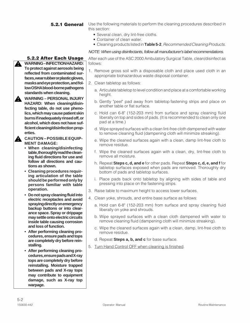
5.2.1 General Use the following materials to perform the cleaning procedures described inthis section:
• Several clean, dry lint-free cloths.• Container of clean water.• Cleaning products listed in Table 5-2, Recommended Cleaning Products.
NOTE: When using disinfectants, follow all manufacturer's label recommendations.
5.2.2 After Each Usage After each use of the ASC 2000 Ambulatory Surgical Table, clean/disinfect asfollows:
1. Remove gross soil with a disposable cloth and place used cloth in anappropriate biohazardous waste disposal container.
2. Clean tabletop as follows:
a. Articulate tabletop to level condition and place at a comfortable workingheight.
b. Gently "peel" pad away from tabletop fastening strips and place onanother table or flat surface.
c. Hold can 6-8" (152-203 mm) from surface and spray cleaning fluidliberally on top and sides of pads. (It is recommended to clean only onepad at a time.)
d. Wipe sprayed surfaces with a clean lint-free cloth dampened with waterto remove cleaning fluid (dampening cloth will minimize streaking).
e. Wipe the cleaned surfaces again with a clean, damp lint-free cloth toremove residue.
f. Wipe the cleaned surfaces again with a clean, dry, lint-free cloth toremove all moisture.
h. Repeat Steps c, d, and e for other pads. Repeat Steps c, d, e, and f fortabletop surfaces exposed when pads are removed. Thoroughly drybottom of pads and tabletop surfaces.
i. Place pads back onto tabletop by aligning with sides of table andpressing into place on the fastening strips.
3. Raise table to maximum height to access lower surfaces.
4. Clean yoke, shrouds, and entire base surface as follows:
a. Hold can 6-8" (152-203 mm) from surface and spray cleaning fluidliberally on yoke and shrouds.
b. Wipe sprayed surfaces with a clean cloth dampened with water toremove cleaning fluid (dampening cloth will minimize streaking).
c. Wipe the cleaned surfaces again with a clean, damp, lint-free cloth toremove residue.
d. Repeat Steps a, b, and c for base surface.
5. Turn Hand Control OFF when cleaning is finished.
WARNING – INFECTION HAZARD:To protect against aerosols beingreflected from contaminated sur-faces, wear rubber or plastic gloves,masks and eye protection, and fol-low OSHA blood-borne pathogensstandards when cleaning.WARNING – PERSONAL INJURYHAZARD: When cleaning/disin-fecting table, do not use pheno-lics, which may cause patient skinburns if inadequately rinsed off, oralcohol, which does not have suf-ficient cleaning/disinfection prop-erties.CAUTION – POSSIBLE EQUIP-MENT DAMAGE:• When cleaning/disinfecting
table, thoroughly read the clean-ing fluid directions for use andfollow all directions and cau-tions as shown.
• Cleaning procedures requir-ing articulation of the tableshould be performed only bypersons familiar with tableoperation.
• Do not spray cleaning fluid intoelectric receptacles and avoidspraying directly on emergencybackup buttons or into clear-ance space. Spray or drippagemay settle onto electric circuitsinside table causing corrosionand loss of function.
• After performing cleaning pro-cedures, ensure pads and topsare completely dry before rein-stalling.
• After performing cleaning pro-cedures, ensure pads and X-raytops are completely dry beforereinstalling. Moisture trappedbetween pads and X-ray topsmay contribute to equipmentdamage, such as X-ray topwarpage.

5-3Routine Maintenance Operator Manual 150830-442
5.2.3 End-Of-Day CleaningProcedure
At the end of each day, perform the cleaning procedures as outlined inSection 5.2.2, After Each Usage.
5.2.4 Weekly CleaningProcedure
After each weekly use of the ASC 2000 Ambulatory Surgical Table, clean/disinfect table as follows:
1. Perform Steps 1 through 4 of the Section 5.2.2, After Each Usage.
2. Check table casters for any accumulated debris and clean as follows:
a. Ensure the floor locks are properly engaged (Floor Lock Pedal de-pressed in Lock position). If not, adjust per Step 3 of Section 3, InstallationInstructions, of this manual.
b. Hold cleaner spray can 6-8" (152-203 mm) from caster and spraycleaning fluid liberally on the caster.
c. Wipe caster with a cloth, dampened with water, to remove cleaning fluidand debris.
d. Perform Steps b and c for the remaining three casters.
3. Articulate table through all movements and clean all additional surfacesexposed during these articulations as follows:
a. Hold spray cleaner can 6-8" (152-203 mm) from surface to be cleanedand spray cleaning fluid liberally on surface.
b. Wipe sprayed surfaces with a clean lint-free cloth, dampened with waterto remove cleaning fluid.
c. Wipe cleaned surfaces again with a clean, damp, lint-free cloth removeany remaining residue.
4. Turn Hand Control OFF when finished with cleaning procedure.
5.3 Bi-WeeklyMaintenance
Operate each ASC 2000 Ambulatory Surgical Table function (refer to Section 4,Operating Instructions). Operation should be smooth and quiet. If table operationis not smooth, have a qualified technician repair the table. Never permit inexpe-rienced, unqualified persons to attempt to make any repairs to the table.
5.4 MonthlyMaintenance
Check ASC 2000 Ambulatory Surgical Table casters and floor locks for anyaccumulated debris and clean as follows:
1. Ensure the floor locks are properly engaged (Floor Lock Pedal depressedin Lock position). If not, adjust per Step 3 of Section 3, Installation Instruc-tions, of this manual.
2. Hold spray cleaner can 6-8" (152-203 mm) from caster and spray cleaningfluid liberally on the caster.
3. Wipe caster with a cloth, dampened with water, to remove cleaning fluid anddebris. Ensure items such as suture, oils, and floor wax are removed.
4. Perform Steps 2 and 3 for the remaining three casters.

5-4150830-442 Operator Manual Routine Maintenance
5.5 Battery ChargingProcedure
IMPORTANT: Batteries are recharged automatically as long as the BATTERYSWITCH is set to ON and the AC power is connected to the ASC 2000Ambulatory Surgical Table.
Batteries will require recharging on a periodic basis depending on frequencyof table usage. Low or discharged battery conditions are indicated by LowBattery Indicator on the Hand Control (see Fig. 4-2 and Section 4.3.2).
Lead acid batteries last longer if not fully discharged. Therefore, to obtain thelongest life and capacity from your ASC 2000 Ambulatory Surgical Tablebatteries, always connect AC power cord to table base and plug into anappropriate AC receptacle as often as possible, and as long as possible, withthe BATTERY SWITCH set to ON. If this is not always possible, rechargebatteries at the following times:
• Every 10 days when the table is in normal service; more often if usagedemands.
• Whenever Low Battery Indicator is ON.
• If the table remains in extended storage for longer than three months;batteries must be charged every three months.
NOTE: If the sealed lead-acid gel electrolyte-type batteries do not charge,check for the following:
1) F1 and F2 fuses are blown - replace (see Fig. 2-4 and Section 5.7,Replacement Parts).
2) AC power cord is defective - replace if necessary.
3) BATTERY SWITCH is OFF.
4) Charger Circuit is not operating.
Recharge batteries as follows:
1. Connect AC power cord to table base and plug into an appropriate ACreceptacle.
2. Turn the BATTERY SWITCH to ON.
3. Allow approximately 48 hours for full battery charge.
4. Verify Low Battery Indicator on the Hand Control is OFF. Disconnect ACpower.
5-5Routine Maintenance Operator Manual 150830-442
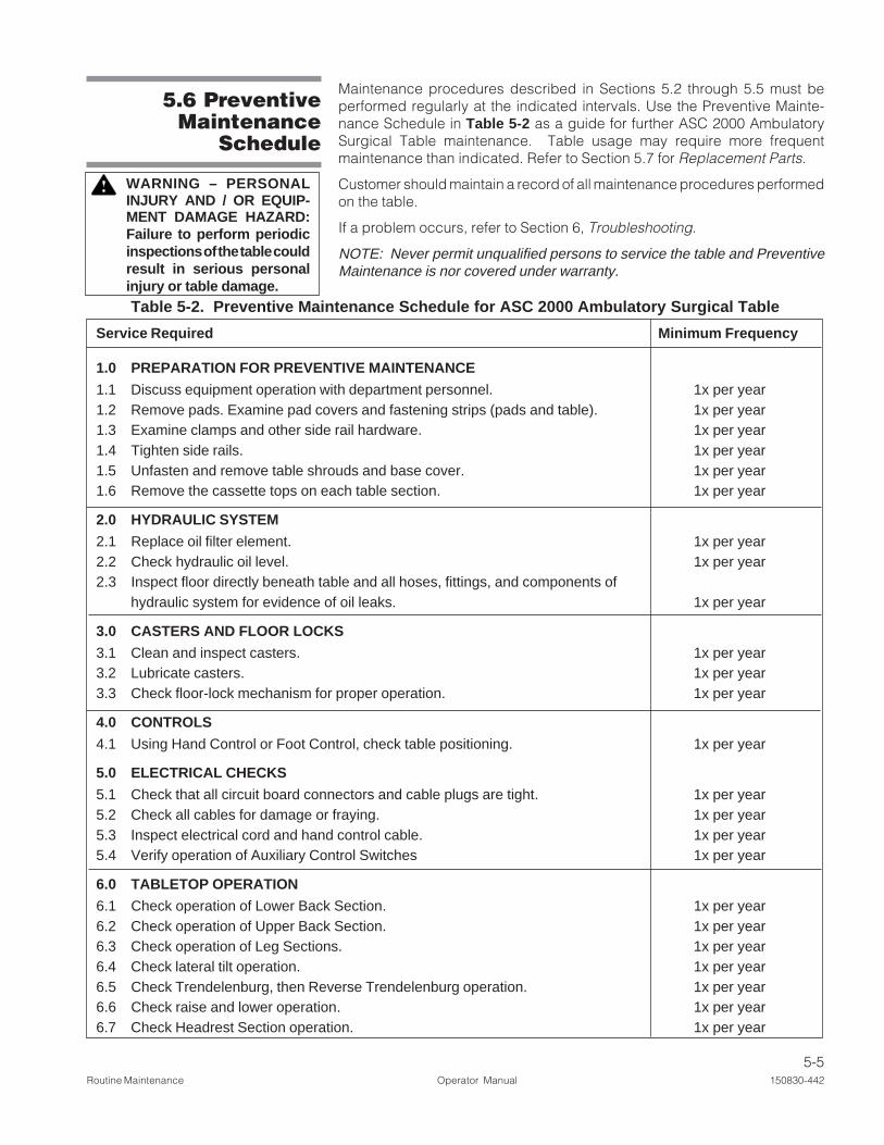
5.6 PreventiveMaintenance
Schedule
Table 5-2. Preventive Maintenance Schedule for ASC 2000 Ambulatory Surgical Table
Service Required Minimum Frequency
1.0 PREPARATION FOR PREVENTIVE MAINTENANCE
1.1 Discuss equipment operation with department personnel. 1x per year1.2 Remove pads. Examine pad covers and fastening strips (pads and table). 1x per year1.3 Examine clamps and other side rail hardware. 1x per year1.4 Tighten side rails. 1x per year1.5 Unfasten and remove table shrouds and base cover. 1x per year1.6 Remove the cassette tops on each table section. 1x per year
2.0 HYDRAULIC SYSTEM
2.1 Replace oil filter element. 1x per year2.2 Check hydraulic oil level. 1x per year2.3 Inspect floor directly beneath table and all hoses, fittings, and components of
hydraulic system for evidence of oil leaks. 1x per year
3.0 CASTERS AND FLOOR LOCKS
3.1 Clean and inspect casters. 1x per year3.2 Lubricate casters. 1x per year3.3 Check floor-lock mechanism for proper operation. 1x per year
4.0 CONTROLS
4.1 Using Hand Control or Foot Control, check table positioning. 1x per year
5.0 ELECTRICAL CHECKS
5.1 Check that all circuit board connectors and cable plugs are tight. 1x per year5.2 Check all cables for damage or fraying. 1x per year5.3 Inspect electrical cord and hand control cable. 1x per year5.4 Verify operation of Auxiliary Control Switches 1x per year
6.0 TABLETOP OPERATION
6.1 Check operation of Lower Back Section. 1x per year6.2 Check operation of Upper Back Section. 1x per year6.3 Check operation of Leg Sections. 1x per year6.4 Check lateral tilt operation. 1x per year6.5 Check Trendelenburg, then Reverse Trendelenburg operation. 1x per year6.6 Check raise and lower operation. 1x per year6.7 Check Headrest Section operation. 1x per year
Maintenance procedures described in Sections 5.2 through 5.5 must beperformed regularly at the indicated intervals. Use the Preventive Mainte-nance Schedule in Table 5-2 as a guide for further ASC 2000 AmbulatorySurgical Table maintenance. Table usage may require more frequentmaintenance than indicated. Refer to Section 5.7 for Replacement Parts.
Customer should maintain a record of all maintenance procedures performedon the table.
If a problem occurs, refer to Section 6, Troubleshooting.
NOTE: Never permit unqualified persons to service the table and PreventiveMaintenance is nor covered under warranty.
WARNING – PERSONALINJURY AND / OR EQUIP-MENT DAMAGE HAZARD:Failure to perform periodicinspections of the table couldresult in serious personalinjury or table damage.
5-6150830-442 Operator Manual Routine Maintenance
Table 5-2. Preventive Maintenance Schedule for ASC 2000 Ambulatory Surgical Table (Cont'd)
Service Required Minimum Frequency
7.0 TABLE RIGIDITY
7.1 Check tabletop for any horizontal or vertical play. 1x per year7.2 Check side tilt mechanism for any play. 1x per year7.3 Check raise/lower mechanism for any play. 1x per year7.4 Check for any play in floor-lock legs. 1x per year
8.0 FINAL TEST
8.1 Examine all lubricated parts. Apply lubrication as needed. 1x per year8.2 Secure all covers and shrouds. 1x per year8.3 Reinstall any pads that were removed. Check for rips, tears, etc. 1x per year8.4 Inspect area to ensure removal of all materials used during inspection. 1x per year
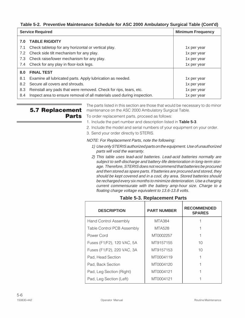
5.7 ReplacementParts
The parts listed in this section are those that would be necessary to do minormaintenance on the ASC 2000 Ambulatory Surgical Table.
To order replacement parts, proceed as follows:1. Include the part number and description listed in Table 5-3.2. Include the model and serial numbers of your equipment on your order.3. Send your order directly to STERIS.
NOTE: For Replacement Parts, note the following:
1) Use only STERIS authorized parts on the equipment. Use of unauthorizedparts will void the warranty.
2) This table uses lead-acid batteries. Lead-acid batteries normally aresubject to self-discharge and battery-life deterioration in long-term stor-age. Therefore, STERIS does not recommend that batteries be procuredand then stored as spare parts. If batteries are procured and stored, theyshould be kept covered and in a cool, dry area. Stored batteries shouldbe recharged every six months to minimize deterioration. Use a chargingcurrent commensurate with the battery amp-hour size. Charge to afloating charge voltage equivalent to 13.6-13.8 volts.
Table 5-3. Replacement Parts
DESCRIPTION PART NUMBERRECOMMENDED
SPARES
Hand Control Assembly MTA384 1
Table Control PCB Assembly MTA528 1
Power Cord MT0002257 1
Fuses (F1/F2), 120 VAC, 5A MT9157155 10
Fuses (F1/F2), 220 VAC, 3A MT9157153 10
Pad, Head Section MT0004119 1
Pad, Back Section MT0004120 1
Pad, Leg Section (Right) MT0004121 1
Pad, Leg Section (Left) MT0004121 1

6-1Troubleshooting Operator Manual 150830-442
6TROUBLESHOOTING
This section of the manual describes the types of table malfunctions which mayoccur and indicates probable causes.
If you are unable to correct the situation following the Troubleshooting Chart (orif a problem occurs which is not described on the chart) or Routine Mainte-nance Section of this publication, please contact STERIS. Service chargesmay be incurred, consult your warranty for details. A trained service technicianwill promptly place your ASC 2000™ Ambulatory Surgical Table in properworking order.
NOTE: Never permit unqualified persons to service the table. If you are unableto correct a table malfunction, please contact STERIS.
WARNING – PERSONALINJURY AND/OR EQUIP-MENT DAMAGE HAZARD:
• Failure to perform periodicinspections of the tablecould result in seriouspersonal injury or tabledamage.
• Repairs and adjustmentsto this equipment must bemade only by STERIS orSTERIS-trained servicepersonnel. Nonroutinemaintenance performedby unqualified personnelor installation of unautho-rized parts could causepersonal injury, invalidatethe warranty, or result incostly damage. ContactSTERIS regarding serviceoptions.
Calling For Service: First, try to define the situation and determine whetheryou can solve it yourself (see Table 6-1). If you can't solve the situation, callSTERIS and give the following information for the table: model number, serialnumber, date of purchase.
CAUTION – POSSIBLEEQUIPMENT DAMAGE:When moving the table to orfrom the point of use, roll itcarefully at moderate speedand only over smooth floors.Maximum floor clearance is1/4" (6.4 mm). Avoid doorand elevator jambs, and ob-structions greater than 1/4"(6.4 mm). If necessary, lifttable over obstructions, ontotrucks, etc. Lift table evenlyand only by the table base.DO NOT transport articles(including accessories) ontop of the table, and DO NOTuse a forklift to move uncratedtable.
6-2150830-442 Operator Manual Troubleshooting
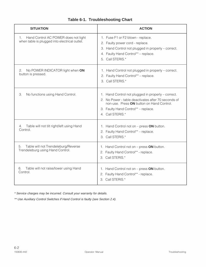
Table 6-1. Troubleshooting Chart
SITUATION ACTION
1. Hand Control AC POWER does not lightwhen table is plugged into electrical outlet.
1. Fuse F1 or F2 blown - replace.
2. Faulty power cord - replace.
3. Hand Control not plugged in properly – correct.
4. Faulty Hand Control** – replace.
5. Call STERIS.*
3. No functions using Hand Control. 1. Hand Control not plugged in properly – correct.
2. No Power - table deactivates after 70 seconds ofnon-use. Press ON button on Hand Control.
3. Faulty Hand Control** – replace.
4. Call STERIS.*
4. Table will not tilt right/left using HandControl.
1. Hand Control not on – press ON button.
2. Faulty Hand Control** – replace.
3. Call STERIS.*
5. Table will not Trendeleburg/ReverseTrendeleburg using Hand Control.
1. Hand Control not on – press ON button.
2. Faulty Hand Control** - replace.
3. Call STERIS.*
6. Table will not raise/lower using HandControl.
1. Hand Control not on – press ON button.
2. Faulty Hand Control** - replace.
3. Call STERIS.*
* Service charges may be incurred. Consult your warranty for details.
** Use Auxiliary Control Switches if Hand Control is faulty (see Section 2.4).
2. No POWER INDICATOR light when ONbutton is pressed.
1. Hand Control not plugged in properly – correct.
2. Faulty Hand Control** – replace.
3. Call STERIS.*

7-1Disposal Hazards Operator Manual 150830-442
7DISPOSAL HAZARDS
The following materials are contained within the table. When disposing of thetable or its parts, ensure the proper disposal of hazardous and other regulatedwaste in compliance with federal, state, and local regulations.
Lead Acid (Pb/H2SO4): gelled cell batteries located in the table base at thehead end of the table. Approximate weight 5 lb (2 kg).
Lead (Pb) in Solder: contained in solder on circuit boards and in somemiscellaneous wire connections. Minute amounts.
Electronic and Electrical Parts: not known to require special disposal at dateof this manual.
Metal Parts: made from aluminum (Al), steel (Fe), cast iron (Fe), copper (Cu),and copper alloys (Cu/x), plastic, synthetic rubber, plating (Cr, Ni, Zn, Au), andadhesives not known to require special disposal methods at date of thismanual.
Hydraulic Oil: contained in hydraulic components located in the base,column, seat section, back section, and hydraulic system lines and hoses.
WARNING – DISPOSALHAZARD: This product con-tains materials which mayrequire disposal through ap-propriately licensed andpermitted hazardous wastemanagement firms.
CAUTION – POSSIBLEEQUIPMENT DAMAGE: Useof incorrect hydraulic oil mayseverely damage the tableand/or cause malfunction.Contact STERIS for properhydraulic oil.


![INDEX [wakerly.org]wakerly.org/DDPP/DDPP3_mkt/ddpp3ix.pdf · INDEX Note: Page numbers for ... clocked assignment operator, := 628 clocked truth-table operator, :> 628 ... 243 Brayton,](https://static.fdocuments.us/doc/165x107/5ace2c0d7f8b9a93268e77ed/index-note-page-numbers-for-clocked-assignment-operator-628-clocked.jpg)


