
Operations Manual - TE 40 / TE 40-AVR Rotary hammer · Manual de instrucciones es Istruzioni...
17
TE 40 / TE 40-AVR *274306* 274306 Hilti Corporation LI-9494 Schaan Tel.: +423 / 234 21 11 Fax: +423 / 234 29 65 www.hilti.com Hilti = registered trademark of Hilti Corp., Schaan W 3161 0107 00-Pos. 1 1 Printed in Liechtenstein © 2007 Right of technical and programme changes reserved S. E. & O. 274306 / A Bedienungsanleitung de Operating instructions en Mode d’emploi fr Manual de instrucciones es Istruzioni d’uso it Gebruiksaanwijzing nl Brugsanvisning da Bruksanvisning no Bruksanvisning sv Käyttöohje fi Manual de instruções pt δηγιες ρησεως el Lietoßanas pamåcîba lv Instrukcija lt Kasutusjuhend et 3 2 1 10 4 1 2 3 11 D C B A 13 7:30 07 1 2 12
Transcript of Operations Manual - TE 40 / TE 40-AVR Rotary hammer · Manual de instrucciones es Istruzioni...
TE 40 /TE 40-AVR
*274306*
2743
06
Hilti CorporationLI-9494 SchaanTel.: +423 / 234 21 11Fax: +423 / 234 29 65www.hilti.com
Hilti = registered trademark of Hilti Corp., Schaan W 3161 0107 00-Pos. 1 1 Printed in Liechtenstein © 2007Right of technical and programme changes reserved S. E. & O.
274306 / A
Bedienungsanleitung de
Operating instructions en
Mode d’emploi fr
Manual de instrucciones es
Istruzioni d’uso it
Gebruiksaanwijzing nl
Brugsanvisning da
Bruksanvisning no
Bruksanvisning sv
Käyttöohje fi
Manual de instruções pt
�δηγιες �ρησεως el
Lietoßanas pamåcîba lv
Instrukcija lt
Kasutusjuhend et
32
1
10
4
1
23
11
D
C
B
A
137:
30a.
m
07
1
2
12
16
3
5
8
7
4
2
9
1
3
4
5
2
235 24/6
7
1
3
3
2
1
5
2
1
4
3
7
1
3
4
2
6
4
5
32 6
1
4
5
32
4
6
1
8
3
2
1
9
1
TE 40 / TE 40‑AVR combi hammerIt is essential that the operating instructionsare read before the power tool is operatedfor the first time.
Always keep these operating instructionstogether with the power tool.
Ensure that the operating instructions arewith the power tool when it is given to otherpersons.
Contents Page1. General information 172. Description 183. Insert tools, accessories 204. Technical data 215. Safety rules 226. Before use 247. Operation 258. Care and maintenance 289. Troubleshooting 29
10. Disposal 3011. Manufacturer’s warranty - tools 3012. EC declaration of conformity 31
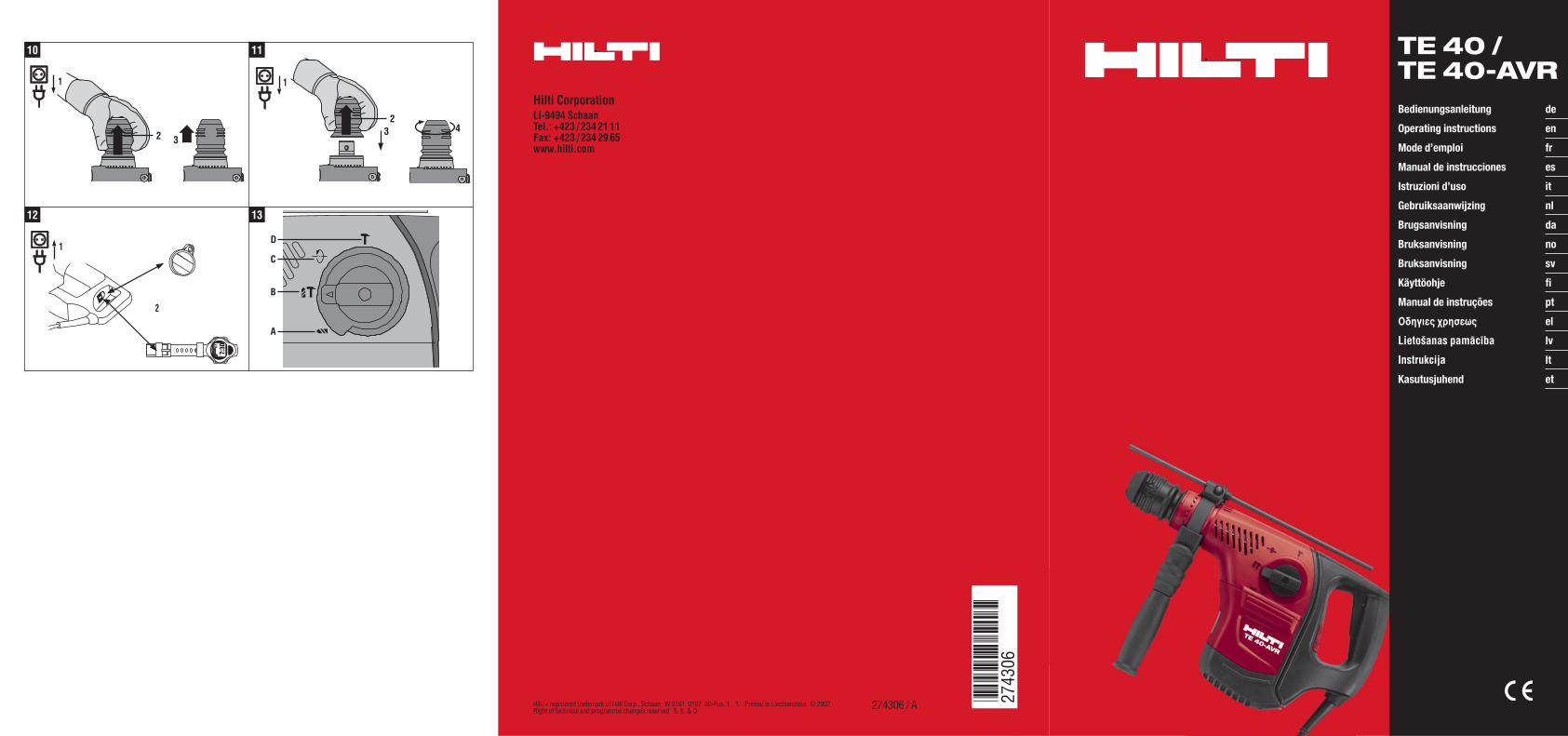
Operating controls and indicators 1
@Chuck
;Function selector switch
=Control switch
%Supply cord
&Side handle
(Depth gauge
)Service indicator
+Theft protection indicator (option)
§AVR active vibration reduction (only
TE 40‑AVR)
1. General information1.1 Safety notices and their meaning
WARNINGDraws attention to a potentially dangerous situationthat could lead to serious personal injury or fatality.
CAUTIONDraws attention to a potentially dangerous situationthat could lead to slight personal injury or damage tothe equipment or other property.
NOTEDraws attention to an instruction or other usefulinformation.
1.2 Explanation of the pictograms and otherinformation
Warning signs
Generalwarning
Warning:electricity
Warning: hotsurface
Obligation signs
Wear eyeprotection
Wear a hardhat
Wear earprotection
Wearprotective
gloves
en
17
Wearbreathingprotection
Symbols
Read theoperating
instructionsbefore use.
Return wastematerial forrecycling.
Drillingwithout
hammering
Hammerdrilling
Chiseling Chisel positionadjustment
Volts Amps
Watts Alternatingcurrent
Hertz Rated speedunder no load
Revolutionsper minute
Diameter Doubleinsulated
Equipped withtheft
protectionsystem
Lock symbol
1 These numbers refer to the corresponding illustra-tions. The illustrations can be found on the fold-outcover pages. Keep these pages open while studyingthe operating instructions.In these operating instructions, the designation “thepower tool” always refers to the TE 40 or TE 40-AVRcombihammer.
Location of identification data on the power toolThe type designation can be found on the type iden-tification plate and the serial number on the side ofthe motor housing. Make a note of this data in youroperating instructions and always refer to it whenmaking an enquiry to your Hilti representative orservice department.
Type:
Serial no.:
2. Description2.1 Use of the product as directed
The power tool is an electrically-powered combihammer with pneumatic hammering mechanism.The power tool is intended for drilling in concrete, masonry, metal and wood.The power tool can also be used for light to medium-duty chiseling work on masonry and for surface finishingon concrete.Working on materials hazardous to the health (e.g. asbestos) is not permissible.The power tool is designed for professional use and may be operated, serviced and maintained only by trained,authorized personnel. This personnel must be informed of any special hazards that may be encountered. Thepower tool and its ancillary equipment may present hazards when used incorrectly by untrained personnel orwhen used not as directed.The working environment may be as follows: construction site, workshop, renovation, conversion or newconstruction.The power tool may be used only in a dry environment.
en
18
Do not use the power tool where there is a risk of fire or explosion.The power tool may be operated only when connected to a power supply providing a voltage and frequency incompliance with the information given on its type identification plate.Modification of the power tool or tampering with its parts is not permissible.To avoid the risk of injury, use only genuine Hilti accessories and insert tools.Observe the information printed in the operating instructions concerning operation, care and maintenance.
2.2 ChuckTE‑C (SDS-plus) quick-change chuckTE‑T (SDS-top) quick-change chuck
2.3 SwitchesSpeed control switch for smooth startingFunction selector switch:Hammer drillingDrilling without hammeringChiselingChisel position adjustment (12 positions)
2.4 GripsVibration-absorbing, pivotable side handleVibration-absorbing grip
2.5 Protective deviceMechanical slip clutchElectronic restart interlock to prevent the power tool starting unintentionally after an interruption in the electricsupply (see section 9 “Troubleshooting”).
2.6 LubricationOil lubrication
2.7 Active vibration reduction (only TE 40‑AVR)The power tool is equipped with an AVR active vibration reduction system which reduces vibration significantlycompared to power tools without active vibration reduction.
2.8 TPS theft protection system (optional)The power tool may be equipped with the TPS theft protection system as an option. If the power tool is equippedwith this feature, it can be unlocked and made ready for operation only through use of the corresponding TPSkey.
2.9 LED indicatorsService indicator LED (see section “Care and maintenance”)Theft protection system indicator (optional) (see section “Operation”)
2.10 Items supplied as standard
1 Power tool with side handle1 Chuck1 Hilti toolbox
en
19
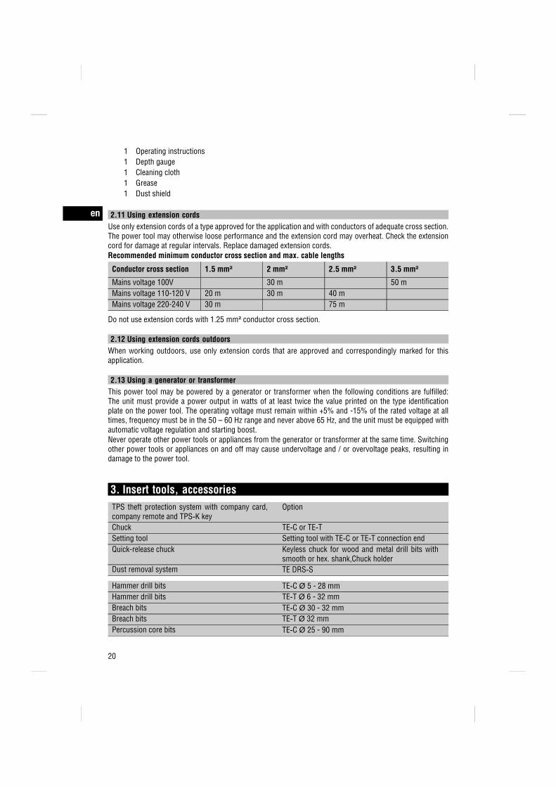
1 Operating instructions1 Depth gauge1 Cleaning cloth1 Grease1 Dust shield
2.11 Using extension cordsUse only extension cords of a type approved for the application and with conductors of adequate cross section.The power tool may otherwise loose performance and the extension cord may overheat. Check the extensioncord for damage at regular intervals. Replace damaged extension cords.Recommended minimum conductor cross section and max. cable lengths
Conductor cross section 1.5 mm² 2 mm² 2.5 mm² 3.5 mm²Mains voltage 100V 30 m 50 mMains voltage 110-120 V 20 m 30 m 40 mMains voltage 220-240 V 30 m 75 m
Do not use extension cords with 1.25 mm² conductor cross section.
2.12 Using extension cords outdoorsWhen working outdoors, use only extension cords that are approved and correspondingly marked for thisapplication.
2.13 Using a generator or transformerThis power tool may be powered by a generator or transformer when the following conditions are fulfilled:The unit must provide a power output in watts of at least twice the value printed on the type identificationplate on the power tool. The operating voltage must remain within +5% and -15% of the rated voltage at alltimes, frequency must be in the 50 – 60 Hz range and never above 65 Hz, and the unit must be equipped withautomatic voltage regulation and starting boost.Never operate other power tools or appliances from the generator or transformer at the same time. Switchingother power tools or appliances on and off may cause undervoltage and / or overvoltage peaks, resulting indamage to the power tool.
3. Insert tools, accessoriesTPS theft protection system with company card,company remote and TPS‑K key
Option
Chuck TE‑C or TE‑TSetting tool Setting tool with TE‑C or TE‑T connection endQuick-release chuck Keyless chuck for wood and metal drill bits with
smooth or hex. shank,Chuck holderDust removal system TE DRS‑S
Hammer drill bits TE‑C Ø 5 - 28 mmHammer drill bits TE‑T Ø 6 - 32 mmBreach bits TE‑C Ø 30 - 32 mmBreach bits TE‑T Ø 32 mmPercussion core bits TE‑C Ø 25 - 90 mm
en
20
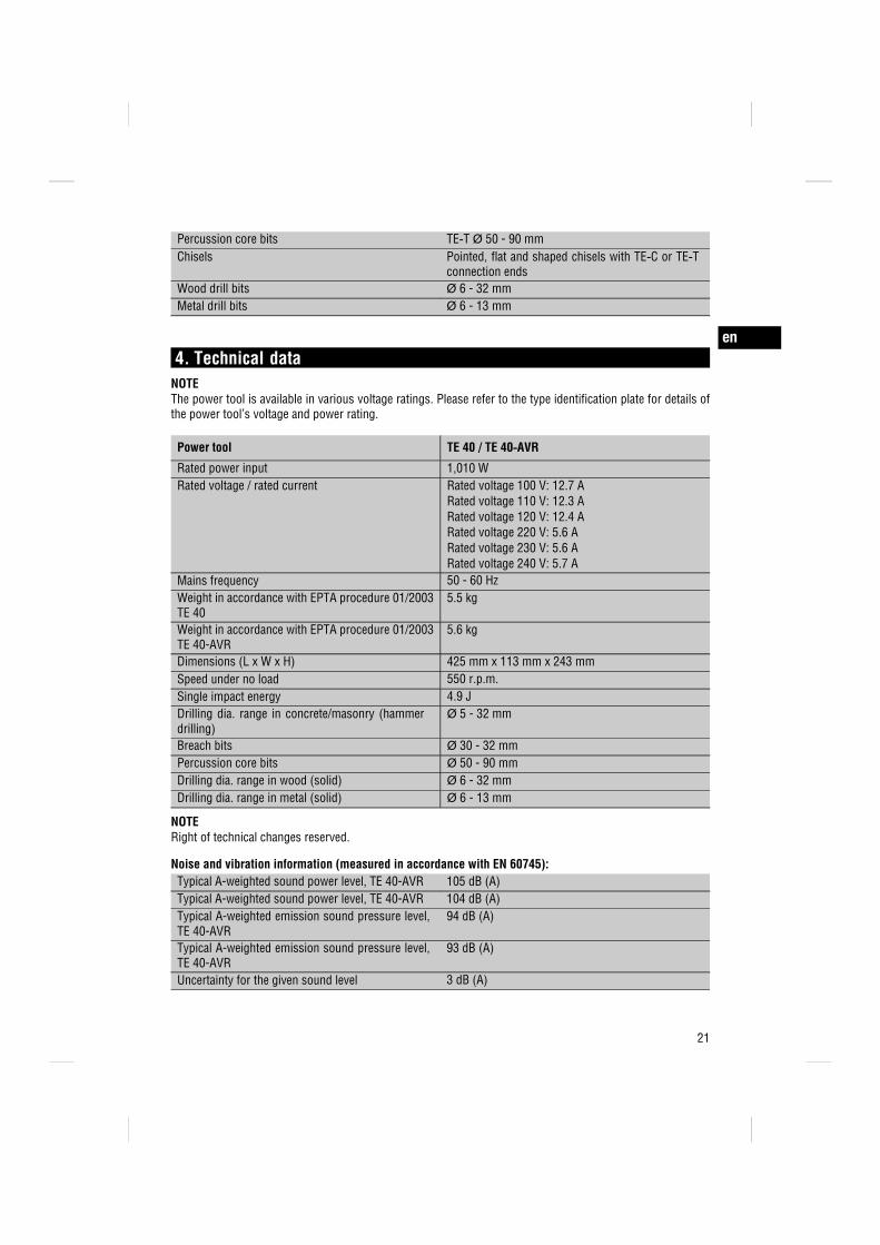
Percussion core bits TE‑T Ø 50 - 90 mmChisels Pointed, flat and shaped chisels with TE‑C or TE‑T
connection endsWood drill bits Ø 6 - 32 mmMetal drill bits Ø 6 - 13 mm
4. Technical dataNOTEThe power tool is available in various voltage ratings. Please refer to the type identification plate for details ofthe power tool’s voltage and power rating.
Power tool TE 40 / TE 40‑AVR
Rated power input 1,010 WRated voltage / rated current Rated voltage 100 V: 12.7 A
Rated voltage 110 V: 12.3 ARated voltage 120 V: 12.4 ARated voltage 220 V: 5.6 ARated voltage 230 V: 5.6 ARated voltage 240 V: 5.7 A
Mains frequency 50 - 60 HzWeight in accordance with EPTA procedure 01/2003TE 40
5.5 kg
Weight in accordance with EPTA procedure 01/2003TE 40-AVR
5.6 kg
Dimensions (L x W x H) 425 mm x 113 mm x 243 mmSpeed under no load 550 r.p.m.Single impact energy 4.9 JDrilling dia. range in concrete/masonry (hammerdrilling)
Ø 5 - 32 mm
Breach bits Ø 30 - 32 mmPercussion core bits Ø 50 - 90 mmDrilling dia. range in wood (solid) Ø 6 - 32 mmDrilling dia. range in metal (solid) Ø 6 - 13 mm
NOTERight of technical changes reserved.
Noise and vibration information (measured in accordance with EN 60745):Typical A-weighted sound power level, TE 40-AVR 105 dB (A)Typical A-weighted sound power level, TE 40-AVR 104 dB (A)Typical A-weighted emission sound pressure level,TE 40-AVR
94 dB (A)
Typical A-weighted emission sound pressure level,TE 40-AVR
93 dB (A)
Uncertainty for the given sound level 3 dB (A)
en
21
Triaxial vibration value for the TE 40‑AVR (vibrationvector sum)
Measured in accordance with EN 60745‑2‑1 prAA:2005
Drilling in metal, (ah, D) < 2.5 m/s²Triaxial vibration value for the TE 40‑AVR (vibrationvector sum)
Measured in accordance with EN 60745‑2‑6 prAB:2005
Hammer drilling in concrete, (ah, HD) 10.7 m/s²Chiseling, (ah, Cheq) 9.9 m/s²Triaxial vibration value for the TE 40 (vibration vectorsum)
Measured in accordance with EN 60745‑2‑1 prAA:2005
Drilling in metal, (ah, D) < 2.5 m/s²Triaxial vibration value for the TE 40 (vibration vectorsum)
Measured in accordance with EN 60745‑2‑6 prAB:2005
Hammer drilling in concrete, (ah, HD) 16.3 m/s²Chiseling, (ah, Cheq) 16.5 m/s²Uncertainty (K) for triaxial vibration value 1.5 m/s²
Other information about the power toolChuck TE‑C (SDS-plus)Chuck TE‑T (SDS-top)Protection class as per EN Protection class II (double insulated) as per
EN 60745
5. Safety rules5.1 General safety rules
WARNING! Read all instructions! Failure to follow allinstructions listed below may result in electric shock,fire and/or serious injury. The term “power tool” inall of the warnings listed below refers to your mains-operated (corded) power tool or battery-operated(cordless) power tool. SAVE THESE INSTRUCTIONS.
5.1.1 Work area safetya) Keep work area clean and well lit. Cluttered and
dark areas invite accidents.b) Do not operate power tools in explosive atmo-
spheres, such as in the presence of flammableliquids, gases or dust. Power tools create sparkswhich may ignite the dust or fumes.
c) Keep children and bystanders away while oper-ating a power tool. Distractions can cause you tolose control.
5.1.2 Electrical safetya) Power tool plugs must match the outlet. Never
modify the plug in any way. Do not use anyadapter plugs with earthed (grounded) power
tools. Unmodified plugs and matching outlets willreduce risk of electric shock.
b) Avoid body contact with earthed or groundedsurfaces such as pipes, radiators, ranges andrefrigerators. There is an increased risk of electricshock if your body is earthed or grounded.
c) Do not expose power tools to rain or wet con-ditions. Water entering a power tool will increasethe risk of electric shock.
d) Do not abuse the cord. Never use the cord forcarrying, pulling or unplugging the power tool.Keep cord away from heat, oil, sharp edgesor moving parts. Damaged or entangled cordsincrease the risk of electric shock.
e) When operating a power tool outdoors, use anextension cord suitable for outdoor use. Use of acord suitable for outdoor use reduces the risk ofelectric shock.
5.1.3 Personal safetya) Stay alert, watch what you are doing and use
common sense when operating a power tool. Donot use a power tool while you are tired or under
en
22
the influence of drugs, alcohol or medication. Amoment of inattention while operating power toolsmay result in serious personal injury.
b) Use safety equipment. Always wear eye pro-tection. Safety equipment such as dust mask,non-skid safety shoes, hard hat, or hearing pro-tection used for appropriate conditions will reducepersonal injuries.
c) Avoid accidental starting. Ensure the switch isin the off-position before plugging in. Carryingpower tools with your finger on the switch orplugging in power tools that have the switch oninvites accidents.
d) Remove any adjusting key or wrench beforeturning the power tool on. A wrench or a key leftattached to a rotating part of the power tool mayresult in personal injury.
e) Do not overreach. Keep proper footing and bal-ance at all times. This enables better control ofthe power tool in unexpected situations.
f) Dress properly. Do not wear loose clothing orjewellery. Keep your hair, clothing and glovesaway from moving parts. Loose clothes, jewelleryor long hair can be caught in moving parts.
g) If devices are provided for the connection of dustextraction and collection facilities, ensure theseare connected and properly used. Use of thesedevices can reduce dust-related hazards.
5.1.4 Power tool use and carea) Do not force the power tool. Use the correct
power tool for your application. The correct powertool will do the job better and safer at the rate forwhich it was designed.
b) Do not use the power tool if the switch does notturn it on and off. Any power tool that cannot becontrolled with the switch is dangerous and mustbe repaired.
c) Disconnect the plug from the power sourceand/or the battery pack from the power toolbefore making any adjustments, changing ac-cessories, or storing power tools. Such prevent-ive safety measures reduce the risk of starting thepower tool accidentally.
d) Store idle power tools out of the reach of childrenand do not allow persons unfamiliar with thepower tool or these instructions to operate thepower tool. Power tools are dangerous in thehands of untrained users.
e) Maintain power tools. Check for misalignment orbinding of moving parts, breakage of parts and
any other condition that may affect the powertool’s operation. If damaged, have the powertool repaired before use. Many accidents arecaused by poorly maintained power tools.
f) Keep cutting tools sharp and clean. Properlymaintained cutting tools with sharp cutting edgesare less likely to bind and are easier to control.
g) Use the power tool, accessories and tool bitsetc., in accordance with these instructions andin the manner intended for the particular typeof power tool, taking into account the workingconditions and the work to be performed. Use ofthe power tool for operations different from thoseintended could result in a hazardous situation.
5.1.5 Servicea) Have your power tool serviced by a qualified
repair person using only identical replacementparts. This will ensure that the safety of the powertool is maintained.
5.2 Additional safety instructions
5.2.1 Personal safetya) Wear ear protectors. Exposure to noise can cause
hearing loss.b) Use auxiliary handles supplied with the tool.
Loss of control can cause personal injury.c) Always hold the power tool securely with both
hands on the grips provided. Keep the grips dry,clean and free from oil and grease.
d) Breathing protection must be worn if the powertool is used without a dust removal system forwork that creates dust.
e) Improve the blood circulation in your fingers byrelaxing your hands and exercising your fingersduring breaks between working.
f) Avoid touching rotating parts. Switch the powertool on only after bringing it into position atthe workpiece. Touching rotating parts, especiallyrotating drill bits, discs or blades, etc. may lead toinjury.
g) Always lead the supply cord and extension cordaway from the power tool to the rear whileworking. This helps to avoid tripping over the cordwhile working.
5.2.2 Power tool use and carea) Secure the workpiece. Use clamps or a vice
to secure the workpiece. The workpiece is thus
en
23
held more securely than by hand and both handsremain free to operate the power tool.
b) Check that the insert tools used are compatiblewith the chuck system and that they are securedin the chuck correctly.
c) Always work from a secure, safe stance.
5.2.3 Electrical safety
a) Before beginning work, check the working area(e.g. using a metal detector) to ensure that noconcealed electric cables or gas and water pipesare present. External metal parts of the power toolmay become live, for example, when an electriccable is damaged accidentally. This presents aserious risk of electric shock.
b) Check the power tool’s supply cord at regularintervals and have it replaced by a qualifiedspecialist if found to be damaged. Check ex-tension cords at regular intervals and replacethem if found to be damaged. Do not touch thesupply cord or extension cord if it is damagedwhile working. Disconnect the supply cord plugfrom the power outlet. Damaged supply cords orextension cords present a risk of electric shock.
c) Dirty or dusty power tools which have beenused frequently for work on conductive materi-als should be checked at regular intervals at aHilti Service Center. Under unfavorable circum-stances, dampness or dust adhering to the surface
of the power tool, especially dust from conductivematerials, may present a risk of electric shock.
d) When working outdoors with an electric toolcheck to ensure that the tool is connected to theelectric supply by way of a ground fault circuitinterrupter (RCD) with a rating of max. 30 mA(tripping current). Use of a ground fault circuitinterrupter reduces the risk of electric shock.
e) Use of a ground fault circuit interrupter (RCDresidual current device) with a maximum trippingcurrent of 30 mA is recommended.
5.2.4 Work area safetya) Ensure that the workplace is well lit.b) Ensure that the workplace is well ventilated.
Exposure to dust at a poorly ventilated workplacemay result in damage to the health.
c) If the work involves breaking right through, takethe appropriate safety measures at the oppositeside. Parts breaking away could fall out and / orfall down and injure other persons.
5.2.5 Personal protective equipment
The user and any other persons in the vicinity mustwear suitable eye protection, a hard hat, ear pro-tection, protective gloves and breathing protectionwhile the power tool is in use.
6. Before use
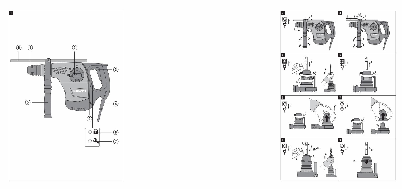
6.1 Fitting and adjusting the side handle 2
CAUTIONRemove the depth gauge from the side handle inorder to avoid injury.
1. Disconnect the supply cord plug from the poweroutlet.
2. Release the side handle clamping band by turningthe handle counterclockwise.
3. Slide the side handle clamping band over thechuck and onto the cylindrical section at the frontend of the power tool.
4. Pivot the side handle into the desired position.5. Secure the side handle by turning the grip clock-
wise.
en
24
6.2 Unlocking the power toolSee section “Operation”
6.3 Use of extension cords and generators ortransformers
Please refer to section 2 “Description”.
7. Operation
CAUTIONIn accordance with the applications for which it isdesigned, the power tool produces a high torque.Always use the side handle and hold the powertool with both hands. The user must be prepared forsudden sticking and stalling of the insert tool.
CAUTIONUse clamps or a vice to hold the workpiece securely.
CAUTIONThe collar at the front end of the gearing section isnot to be used as a gripping surface.
7.1 Preparing for useCAUTIONWear protective gloves when changing drill bits asthe drill bit may get hot during use.
7.1.1 Adjusting the depth gauge 3
1. Release the side handle clamping band by turningthe handle counterclockwise.
2. Pivot the side handle into the desired position.3. Attach the clamp with the depth gauge to the
clamping band at the desired position.4. Release the screw at the depth gauge.5. Adjust the depth gauge to the desired drilling
depth.6. Tighten the screw at the depth gauge firmly.7. Tighten the side handle securely by turning the
grip section. This also clamps the depth gauge inposition.
7.1.2 Chuck with turn-lock system
7.1.2.1 Fitting the insert tool 4
1. Disconnect the supply cord plug from the poweroutlet.
2. Check that the connection end of the insert tool isclean and lightly greased. Clean it and grease it ifnecessary.
3. Open the chuck by turning the chuck sleeve to theright toward the “open brackets” symbol.
4. Push the insert tool into the chuck in any position,as far as it will go, and then rotate the insert tooluntil it can be pushed further in.
5. Close the chuck by turning the chuck sleeve tothe left toward the “closed brackets” symbol.
6. Check that the insert tool has engaged correctlyby pulling it.
7.1.2.2 Removing the insert tool 5
1. Disconnect the supply cord plug from the poweroutlet.
2. Open the chuck by turning the chuck sleeve to theright toward the “open brackets” symbol.
3. Pull the drill bit out of the chuck.
7.1.2.3 Removing the chuck 6
CAUTIONRemove the depth gauge from the side handle andthe insert tool from the chuck in order to avoidinjury.
NOTESet the selector switch to the “Chiseling” positionbefore removing the chuck.
1. Disconnect the supply cord plug from the poweroutlet.
2. Open the chuck by turning the chuck sleeve to theright toward the “open brackets” symbol.
3. Pull the chuck sleeve forward and hold it securely.4. Remove the chuck by pulling it away from the
power tool.
en
25
7.1.2.4 Fitting the chuck 7
CAUTIONRemove the depth gauge from the side handle andthe insert tool from the chuck in order to avoidinjury.
NOTESet the selector switch to the “Chiseling” positionbefore removing the chuck.
1. Disconnect the supply cord plug from the poweroutlet.
2. Open the chuck by turning the chuck sleeve to theright toward the “open brackets” symbol.
3. Grip the chuck sleeve and hold it securely.4. Slide the chuck onto the guide tube from the front
and then release the sleeve.5. Rotate the chuck until it is heard to engage.
7.1.3 Chuck with click-lock system
7.1.3.1 Fitting the insert tool 8
1. Disconnect the supply cord plug from the poweroutlet.
2. Check that the connection end of the insert tool isclean and lightly greased. Clean it and grease it ifnecessary.
3. Check that the sealing lip of the dust shield isclean and in good condition. Clean the dust shieldif necessary or have it replaced if the sealing lipis damaged.
4. Push the insert tool into the chuck and rotate itwhile applying slight pressure until it engages inthe guide grooves.
5. Push the insert tool further into the chuck until itis heard to engage.
6. Check that the insert tool has engaged correctlyby pulling it.
7.1.3.2 Removing the insert tool 9
1. Disconnect the supply cord plug from the poweroutlet.
2. Open the chuck by pulling back the insert toollocking sleeve.
3. Pull the drill bit out of the chuck.
7.1.3.3 Removing the chuck 10
CAUTIONRemove the depth gauge from the side handle andthe insert tool from the chuck in order to avoidinjury.
NOTESet the selector switch to the “Chiseling” positionbefore removing the chuck.
1. Disconnect the supply cord plug from the poweroutlet.
2. Pull the chuck sleeve forward and hold it securely.3. Remove the chuck by pulling it away from the
power tool.
7.1.3.4 Fitting the chuck 11
CAUTIONRemove the depth gauge from the side handle andthe insert tool from the chuck in order to avoidinjury.
NOTESet the selector switch to the “Chiseling” positionbefore removing the chuck.
1. Disconnect the supply cord plug from the poweroutlet.
2. Grip the chuck sleeve, pull it forward and hold itsecurely in this position.
3. Slide the chuck onto the guide tube from the frontand then release the sleeve.
4. Rotate the chuck until it is heard to engage.
7.2 Operation
CAUTIONWorking on the material may cause it to splinter.Wear eye protection and protective gloves. Wearbreathing protection if no dust removal system isused. Splintering material presents a risk of injury tothe eyes and body.
CAUTIONThe work generates noise. Wear ear protectors.Exposure to noise can cause hearing loss.
CAUTIONImprove the blood circulation in your fingers byrelaxing your hands and exercising your fingersduring breaks between working.
en
26
7.2.1 TPS theft protection system (optional)NOTEThe power tool may be equipped with the optionaltheft protection system. If the power tool is equippedwith this feature, it can be unlocked and made readyfor operation only through use of the correspondingTPS key.
7.2.1.1 Unlocking the power tool 12
1. Plug the supply cord into the power outlet. Theyellow theft protection indicator LED blinks. Thepower tool is now ready to receive the signal fromthe TPS key.
2. Hold the TPS key or the TPS watch strap buckleagainst the lock symbol. The power tool is un-locked as soon as the yellow theft protectionindicator LED no longer lights.NOTE If, for example, the electric supply is brieflyinterrupted due to a power failure or disconnectedwhen moving to a different workplace, the powertool remains ready for operation for approx. 20minutes. In the event of a longer interruption, theTPS key must be used again to unlock the powertool.
7.2.1.2 Activation of the theft protection systemfor the power tool
NOTEFurther detailed information on activation and useof the theft protection system can be found in theoperating instructions for the theft protection system.
7.2.2 Drilling without hammering (A) 13
1. Turn the function selector switch until it engagesin the “Drilling without hammering” position. Donot operate the function selector switch while themotor is running.
2. Bring the side handle into the desired positionand check that it is fitted correctly and secured.
3. Plug the supply cord into the power outlet.4. Position the power tool and drill bit at the point
where the hole is to be drilled.5. Press the control switch slowly (drill at a low
speed until the drill bit centers itself in the hole).6. Press the control switch fully to continue drilling
with full power.7. Do not apply excessive pressure. This will not
increase the power tool’s drilling performance.Lower pressure extends the life of the insert tool.
7.2.3 Hammer drilling (B) 13
NOTEWorking at low temperatures: The hammering mech-anism works only when the power tool has reacheda minimum operating temperature. Bring the tip ofthe drill bit or chisel into contact with the workpieceand allow the power tool to run under no load untilit reaches the minimum operating temperature. If ne-cessary, repeat this procedure until the hammeringmechanism begins to operate.
1. Turn the function selector switch until it engagesin the “Hammer drilling” position. Do not operatethe function selector switch while the motor isrunning.
2. Bring the side handle into the desired positionand check that it is fitted correctly and secured.
3. Plug the supply cord into the power outlet.4. Position the power tool and drill bit at the point
where the hole is to be drilled.5. Press the control switch slowly (drill at a low
speed until the drill bit centers itself in the hole).6. Press the control switch fully to continue drilling
with full power.7. Do not apply excessive pressure. This will not in-
crease the power tool’s hammering performance.Lower pressure extends the life of the insert tool.
8. Reduce drilling speed shortly before breakingthrough in order to avoid damage to the surfaceat the rear side.
7.2.4 ChiselingNOTEThe chisel can be adjusted to 12 different positions(in 30° increments). This ensures that flat chisels andshaped chisels can always be set to the optimumworking position.
7.2.4.1 Adjusting the chisel (C) 13
CAUTIONDo not operate the power tool when the selectorswitch is set to “Chisel adjustment”.
1. Turn the function selector switch until it engagesin the “Chisel adjustment” position. Do not oper-ate the function selector switch while the motoris running.
2. Bring the side handle into the desired positionand check that it is fitted correctly and secured.
en
27
3. Rotate the chisel to the desired position.
7.2.4.2 Locking the chisel (D) 13
Turn the function selector switch until it engages inthe “Chiseling” position. Do not operate the functionselector switch while the motor is running.
7.2.4.3 Chiseling(D) 13
1. Plug the supply cord into the power outlet.2. Position the tip of the chisel at the point where
chiseling is to begin.3. Press the control switch fully.
8. Care and maintenanceCAUTIONDisconnect the supply cord plug from the poweroutlet.
8.1 Care of insert toolsClean off dirt and dust deposits adhering to the inserttools and protect them from corrosion by wiping theinsert tools from time to time with an oil-soaked rag.
8.2 Care of the power toolThe outer casing of the power tool is made fromimpact-resistant plastic. Sections of the grip are madefrom a synthetic rubber material.
Never operate the power tool when the ventilationslots are blocked. Clean the ventilation slots carefullyusing a dry brush. Do not permit foreign objects toenter the interior of the power tool. Clean the outsideof the power tool at regular intervals with a slightlydamp cloth. Do not use a spray, steam pressurecleaning equipment or running water for cleaning.This may negatively affect the electrical safety of thepower tool. Always keep the grip surfaces of thepower tool free from oil and grease. Do not usecleaning agents which contain silicone.
8.3 Service indicatorNOTEThe power tool is equipped with a service indicator.
Indicator Constant red light End of service interval - servicing is due. After thelamp lights for the first time, the power tool maycontinue to be used for several hours before theautomatic cut-out is activated. To ensure that thepower tool is always ready for use, it should bereturned to Hilti for servicing in good time.
Blinking red light See section “Troubleshooting”.
8.4 MaintenanceWARNINGRepairs to the electrical section of the power toolmay be carried out only by trained electrical spe-cialists.
Check all external parts of the power tool for damageat regular intervals and check that all controls operatefaultlessly. Do not operate the power tool if parts
are damaged or when the controls do not functionfaultlessly. If necessary, the power tool should berepaired by Hilti Service.
8.5 Checking the power tool after care andmaintenance
After carrying out care and maintenance work onthe power tool, check that all protective and safetydevices are fitted and that they function faultlessly.
en
28
9. Troubleshooting
Fault Possible cause Remedy
The power tool doesn’t start. Interruption in the electric supply. Plug in another electric applianceand check whether it works.
The supply cord or plug is defective. Have it checked by a trainedelectrical specialist and replaced ifnecessary.
Generator with sleep mode. Apply a load to the generator byconnecting another appliance (e.g.a lamp). Subsequently switch thepower tool off and on again.
Other electrical fault. Have it checked by a trainedelectrical specialist.
The electronic restart interlock isactivated after an interruption in theelectric supply.
Switch the power tool off and onagain.
No hammering action. The power tool is too cold. Allow the power tool to warmup to the minimum operatingtemperature.See section: 7.2.3 Hammer drilling(B) 13
The power tool doesn’t startand the LED blinks red.
A fault has occurred in the powertool.
If necessary, the power tool shouldbe repaired by Hilti Service.
The power tool doesn’t startand the LED lights red.
The carbon brushes are worn. Have it checked by a trainedelectrical specialist and replaced ifnecessary.
The power tool doesn’t startand the indicator lamp blinksyellow.
The power tool has not beenunlocked (power tools with optionaltheft protection system).
Use the TPS key to unlock the powertool.
The power tool doesn’t achievefull power.
The extension cord is too long or itsgauge is inadequate.
Use an extension cord of anapproved length and / or ofadequate gauge.
The voltage provided by the electricsupply is too low.
Connect the power tool to a differentpower source.
The drill bit doesn’t rotate. The function selector switch is notengaged or is in the “Chiseling” or“Chisel adjustment” position.
When the motor has stopped, movethe function control switch to the“Drilling without hammering” or“Hammer drilling” position.
The drill bit / chisel can’t bereleased from the chuck.
The chuck is not pulled back fully. Pull the chuck back as far as it willgo and remove the insert tool.
The side handle is not fittedcorrectly.
Release the side handle and refitit correctly so that the clampingband and side handle engage in thegroove.
en
29
10. Disposal
Most of the materials from which Hilti tools or machines are manufactured can be recycled. The materials mustbe correctly separated before they can be recycled. In many countries, Hilti has already made arrangementsfor taking back your old tools for recycling. Please ask your Hilti customer service department or Hiltirepresentative for further information.
For EC countries only
Disposal of electric tools together with household waste is not permissible.
In observance of European Directive 2002/96/EC on waste electrical and electronic equipmentand its implementation in accordance with national law, electric tools that have reached the endof their life must be collected separately and returned to an environmentally compatible recyclingfacility.
11. Manufacturer’s warranty - toolsHilti warrants that the tool supplied is free of defectsin material and workmanship. This warranty is validso long as the tool is operated and handled correctly,cleaned and serviced properly and in accordance withthe Hilti Operating Instructions, and the technicalsystem is maintained. This means that only originalHilti consumables, components and spare parts maybe used in the tool.
This warranty provides the free-of-charge repair orreplacement of defective parts only over the entirelifespan of the tool. Parts requiring repair or replace-ment as a result of normal wear and tear are notcovered by this warranty.
Additional claims are excluded, unless stringent na-tional rules prohibit such exclusion. In particular,Hilti is not obligated for direct, indirect, incidentalor consequential damages, losses or expenses inconnection with, or by reason of, the use of, orinability to use the tool for any purpose. Impliedwarranties of merchantability or fitness for a par-ticular purpose are specifically excluded.
For repair or replacement, send the tool or relatedparts immediately upon discovery of the defect tothe address of the local Hilti marketing organizationprovided.
This constitutes Hilti's entire obligation with regardto warranty and supersedes all prior or contempor-aneous comments and oral or written agreementsconcerning warranties.
en
30
12. EC declaration of conformityDesignation: Combi hammerType: TE 40 / TE 40‑AVRYear of design: 2006
We declare, on our sole responsibility, that thisproduct complies with the following directives andstandards: 89/336/EEC, 98/37/EC, EN 55014‑1,EN 55014‑2, EN 60745‑1, EN 60745‑2‑6,EN 61000‑3‑2, EN 61000‑3‑3.
Hilti Corporation
Peter Cavada Matthias GillnerHead of BU Quality and ProcessManagement
Executive Vice President
Business Area Electric Tools & Ac-cessories
Business Area ElectricTools & Accessories
11 2006 11 2006
en
31


![HIT-CT 1 INJECTION MORTAR - hilti.se HIT- CT1 330 ml foil pack ... 12,0 17,3 25,3 34,9 56,4 79,2 Shear V Rd [kN] ... Rotary hammer TE 2 (-A) – TE 16 (-A) TE 40 – TE 80 Other tools](https://static.fdocuments.us/doc/165x107/5b0183427f8b9ab9598c718f/hit-ct-1-injection-mortar-hiltise-hit-ct1-330-ml-foil-pack-120-173-253.jpg)
