Operations Manual - eng.famu.fsu.edu
20
Operations Manual Design and Development of an Autonomous Underwater Vehicle Team 23 AUVSI Robosub Members: Max Austin (mpa12c) Corey Cavalli (cmc12s) Jordan Clein (jc11y) John Nicholson (jn12c) Erik Olson (eno12b) Ross Richardson (rbr11) Faculty Advisor Dr.Clark Dr. Harvey Sponsor/s Dr.Shih NEEC Instructor/s Dr. Gupta 4/1/2016
Transcript of Operations Manual - eng.famu.fsu.edu

Operations Manual
Design and Development of an Autonomous Underwater Vehicle
Team 23
AUVSI Robosub
Members:
Max Austin (mpa12c)
Corey Cavalli (cmc12s)
Jordan Clein (jc11y)
John Nicholson (jn12c)
Erik Olson (eno12b)
Ross Richardson (rbr11)
Faculty Advisor
Dr.Clark
Dr. Harvey
Sponsor/s
Dr.Shih
NEEC
Instructor/s
Dr. Gupta
4/1/2016

ME Senior Design Team#23(RoboSub) Operations Manual
ii
Table of Contents
Table of Figures ........................................................................................................................................... iv
Table of Tables ............................................................................................................................................. v
Abstract ........................................................................................................................................................ vi
Acknowledgements ..................................................................................................................................... vii
1. Functional Analysis .............................................................................................................................. 1
1.1 Electrical Function .............................................................................................................................. 1
1.2 Mechanical Function ........................................................................................................................... 1
2. Project Specifications ............................................................................................................................ 2
2.1 Electrical Specifications ...................................................................................................................... 2
2.1.1 Main CPU .................................................................................................................................... 3
2.1.2 Microcontrollers ........................................................................................................................... 3
2.1.3 IMU ............................................................................................................................................. 4
2.1.4 Motor Controllers ......................................................................................................................... 4
2.2 Mechanical Specifications .................................................................................................................. 5
3. Product Assembly ................................................................................................................................ 5
3.1 Mechanical Design .............................................................................................................................. 5
3.1.1 Gripper ......................................................................................................................................... 5
3.1.2 Torpedo ........................................................................................................................................ 6
3.1.3 Marker Dropper............................................................................................................................ 6
3.1.4 Thrusters ...................................................................................................................................... 7
4. Operation Instructions ........................................................................................................................... 7
4.1 Lab Testing ......................................................................................................................................... 7
4.1.1 Torpedo/ Gripper Test .................................................................................................................. 7
4.1.2 Marker Dropper Test .................................................................................................................... 7
4.1.3 Control Test ................................................................................................................................. 7
4.2 Water Testing ...................................................................................................................................... 8
4.2.1 Sealing The AUV ......................................................................................................................... 8
4.2.2 Wireless Control .......................................................................................................................... 8
4.2.3 Running Code .............................................................................................................................. 8
5. Troubleshooting .................................................................................................................................... 9

ME Senior Design Team#23(RoboSub) Operations Manual
iii
5.1 Water Leak .......................................................................................................................................... 9
5.2 Overheating ........................................................................................................................................ 9
5.3 Connection Issues ............................................................................................................................... 9
6. Regular Maintenance ............................................................................................................................ 9
6.1 Mechanical Maintenance .................................................................................................................... 9
6.2 Electrical Maintenance ........................................................................................................................ 9
7. Spare Parts .......................................................................................................................................... 10
8. Recommended Approach/Conclusion ................................................................................................. 10
8.1 Thruster Modifications ...................................................................................................................... 10
8.2 Camera Modifications ...................................................................................................................... 10
8.3 Waterproofing Air Tank .................................................................................................................... 10
9. Appendix ............................................................................................................................................. 11

ME Senior Design Team#23(RoboSub) Operations Manual
iv
Table of Figures
Figure 1: Signal Diagram .............................................................................................................................. 1
Figure 2: New Hull Design ........................................................................................................................... 2
Figure 3: Battery Diagram ............................................................................................................................ 2
Figure 4: 12V Battery Circuit ....................................................................................................................... 3
Figure 5: Zotac Mini Computer .................................................................................................................... 3
Figure 6: Sparkfun Razor IMU ..................................................................................................................... 4
Figure 7: L298 H-Bridge motor controller ................................................................................................... 4
Figure 8: Hull Assembled on Frame ............................................................................................................. 5
Figure 9: Gripper Mechanism ....................................................................................................................... 6
Figure 10: Torpedo Design ........................................................................................................................... 6
Figure 11: Marker Dropper ........................................................................................................................... 7
Figure 12: Motor Controller Wiring ........................................................................................................... 13

ME Senior Design Team#23(RoboSub) Operations Manual
v
Table of Tables
Table 1: Battery Requirements ..................................................................................................................... 2
Table 2: Parts List ....................................................................................................................................... 10
Table 3: Spec Sheets ................................................................................................................................... 11

ME Senior Design Team#23(RoboSub) Operations Manual
vi
Abstract The goal of Team 23 is to represent the FAMU/FSU College of Engineering in the 19th annual
AUVSI Robosub competition, which occurs from July 25th to July 31st of 2016. This will be accomplished
through the design, development, and extensive testing of a modular sub which meets all of the
competition requirements provided by the AUVSI Robosub competition. The work process is described
in the manual below as well as operation instructions for the submersible.
Team 23 was not the only team working on the Robosub this year, team 4 of the ECE teams also
worked to reach the goal of reaching the competition this year. This manual will combine the progress of
both teams into one central document to make it easier to follow all the information there is to know
about the submersible.

ME Senior Design Team#23(RoboSub) Operations Manual
vii
Acknowledgements We would like to thank the people who have helped us thus far and the ones who plan to help us
in the future. This includes Kim Hinckley at the Morcom pool for letting us use FSU’s dive pool for
testing. Dr. Gupta and Dr. Shih for guidance and constructive criticism throughout the project and the
course. Dr. Clark for pushing us to set high goals and achieve them. Dr. Harvey and Dr. Hooker for their
support and suggestions and the ME and ECE department for funding our senior design project.

ME Senior Design Team#23(RoboSub) Operations Manual
1
1. Functional Analysis
1.1 Electrical Function
The intended function of this project is to design an autonomous underwater vehicle, or AUV. In
order to accomplish this several components needed to be addressed: the main electronics (the CPU), a
waterproof electronics housing (hull), cameras and thrusters for navigation, and the mechanical
components of subsystems to perform various tasks such as the marker dropper, gripper and torpedo
firing mechanism. The major electronics hardware required to control the AUV is comprised of a main
processing unit (MPU), microcontrollers, and motor drivers. Each subsystem has its own set of
instructions and code which interacts with the MPU. Below is a signal diagram showing how the
electronics communicate with one another in their subsystems. The legend on the upper left corner of
Figure 1 organizes the components into their specific subsystems.
Figure 1: Signal Diagram
1.2 Mechanical Function
A well designed hull was one of the most crucial requirements for the entire project. A good
balance between size and weight had to be found. The size is an important factor in that it must be large
enough to hold all the electronics hardware but not but not have excess volume that caused too much
buoyancy. The electronics housing is an important factor in the AUV since it will be housing all of the
electronic hardware and will need to be watertight to prevent water shorting the electronics. A CAD of the
hull can be seen in figure 2 below. The waterproofing will be done by using a weather strip as an o-ring
around the inside of the hull. There are then six latches that put pressure on an acrylic lid. The pressure
applied to the lid from the latches creates a watertight seal around the top. The housing is also important
in that it is the main medium through which the heat generated by the electronics will be dissipated. If the
heat dissipated is not enough, then the electronics could overheat, which could then cause small problems
circuitry problems such as shorts. The final design that was chosen is shown above and is made of
ME Senior Design Team#23(RoboSub) Operations Manual
2
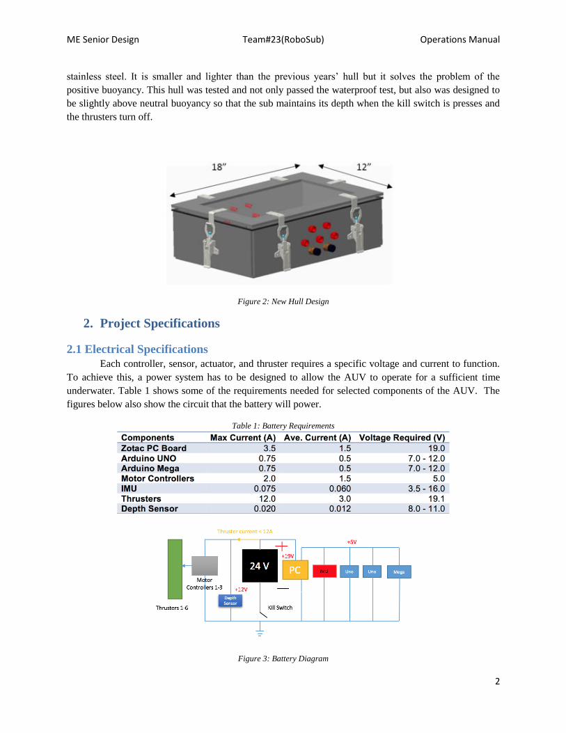
stainless steel. It is smaller and lighter than the previous years’ hull but it solves the problem of the
positive buoyancy. This hull was tested and not only passed the waterproof test, but also was designed to
be slightly above neutral buoyancy so that the sub maintains its depth when the kill switch is presses and
the thrusters turn off.
Figure 2: New Hull Design
2. Project Specifications
2.1 Electrical Specifications
Each controller, sensor, actuator, and thruster requires a specific voltage and current to function.
To achieve this, a power system has to be designed to allow the AUV to operate for a sufficient time
underwater. Table 1 shows some of the requirements needed for selected components of the AUV. The
figures below also show the circuit that the battery will power.
Table 1: Battery Requirements
Figure 3: Battery Diagram

ME Senior Design Team#23(RoboSub) Operations Manual
3
Figure 3 above shows the main power diagram for the AUV. The main components are all
powered by a 24 V battery along with voltage regulators which cut down the power to the components
that do not require as much.
Figure 4: 12V Battery Circuit
The Figure above shows the secondary power diagram for the AUV. The functional purpose of
this battery is to power the cooling fans along with the relays and air valves for the pneumatic system.
This battery also serves aesthetic purposes such as powering the LEDs in the sub or lighting up the kill
switch.
2.1.1 Main CPU
In order to integrate all of the subs functions to communicate with one another a main processing unit
is need. The Zotac computer acts as the main processing unit for the AUV. As the MPU, the Zotac is
essentially the sub’s “brain” and is responsible for most of the high-level communication. The Zotac is
where the image processing takes place which then communicates to other peripherals of the sub. The
MPU interfaces with one Arduino Mega and two Arduino UNO microcontrollers. The Zotac makes use of
its USB ports to establish bidirectional UART serial communication links with the microcontrollers. The
information is sent to the Arduinos to control various hardware such as the thrusters, and depth sensor.
The Zotac computer also utilizes two Logitech webcams connected via USB for vision information. The
MPU receives power from an external 19V/ 4mA universal laptop battery. The Zotac also acts as a power
source to the microcontrollers and IMU.
Figure 5: Zotac Mini Computer
2.1.2 Microcontrollers
Each serial device needs a “bridge” to communicate with the MPU. The Arduino UNO is a
perfect solution to handle this communication. Two Arduino UNO’s will be used in the AUV. Each
Arduino will control a peripheral: actuators, hydrophones, etc. This will take the serial communication
from each subsystem and allow control over USB from the MPU. This device was selected to be

ME Senior Design Team#23(RoboSub) Operations Manual
4
specifically used for motor control. It contains more pins to be used with all six thrusters. This allows
thruster control to be sent to only one device instead of multiple Arduinos. It also allows for more
processing power so that it can be directly attached to the IMU stabilizing unit. It is powered via USB and
will be controlled through USB from the MPU as well.
2.1.3 IMU
The Inertial Measurement Unit, or IMU, is integral in maintaining the orientation of the AUV. It
has nine degrees of freedom and outputs data in the x,y, and z planes. This particular IMU was a very cost
effective model that was able to easily do the tasks needed with this project and communicate with the
Zotac which adjusts the thrusters accordingly.
Figure 6: Sparkfun Razor IMU
2.1.4 Motor Controllers
There were three L298 H-Bridge motor controllers that were used in the AUV, both of which
were very similar. This year the team purchases a new motor controller to replace the older model and
make all of the controllers the same. The motor controller used is the CanaKit driver, with the following
specifications:
Figure 7: L298 H-Bridge motor controller

ME Senior Design Team#23(RoboSub) Operations Manual
5
2.2 Mechanical Specifications
The hull without the frame weighs 75 lbs and displaces slightly over that to achieve a small
degree of buoyancy when submerged. If needed buoyancy foam can be added to the bottom of the hull to
achieve neutral buoyancy if it is too heavy. Furthermore weights can be added to the hull if it is too
buoyant.
3. Product Assembly
There are a lot of connections that need to be made throughout the AUV in order for it to operate
correctly. The signal diagram from figure 1 shows all the top level connections that need to be made, This
section contains more detailed wiring diagrams as well as instructions for attaching the hardware to one
another.
3.1 Mechanical Design
The mechanical design consists of the hull and frame assembly. The primary purpose of this design was
to keep it simple and functional. The main idea behind the design of the hull was to achieve neutral
buoyancy to put as l
Figure 8: Hull Assembled on Frame
3.1.1 Gripper
The gripper mechanism must be able to grasp and continuously apply pressure to a variety of
small objects throughout the course. The grip must constrain at least 3 degrees of freedom of the object
throughout movement in all directions. The gripper must be controlled effectively by the microcontroller
and interface with the cameras to ensure accuracy in securing a target.
Figure X shows the actuator the team has decided to go with for the gripping mechanism. This
model runs off of compressed air. The camera would detect an object on the bottom of the pool and would
activate an air compressor which would close the claw and keep it inside of its grip. This model will be
improved upon this year by redesigning the physical gripper but keeping the same principles intact. The
gripper for this AUV is mounted in the front.

ME Senior Design Team#23(RoboSub) Operations Manual
6
Figure 9: Gripper Mechanism
3.1.2 Torpedo
The portion of this system that the team is focused on redesigning is the physical projectile. The
problem of the floating torpedoes will invariably effect scoring during the competition. Upon
investigation of an old torpedo It was found that the object is made out of either cast or machined ABS
plastic that contains a metal rod in its center and a magnet to attach to the projectile system. The use of a
metal rod gave structure and assisted in the attempt to correct buoyancy. With the knowledge that this had
less than optimal buoyancy but the system is still designed for these to particular projectiles to fit into it
the team chose to look at a manufacturing change. Figure 4 shows a remade CAD design made to mimic
the previous design. The manufacturing methods that will be used to replicate this is 3D printing. Using
3D printed ABS rapid inexpensive prototyping is available to change buoyancy based on core size and
infill. This will also allow the altering of core materials with ease to produce the ideal weight addition to
the sub. Additionally the rapid prototyping will allow for slight shape changes to optimize trajectory in
water.
Figure 10: Torpedo Design
3.1.3 Marker Dropper
The design used for the marker dropper came from a design adopted from a previous FAMU-FSU
RoboSub team. The decision to continue with this design came down to its simplicity and effectiveness.
The mechanical subsystem is made out of aluminum 6061 and contains a parabolic track where two steel
balls will be in place. The parabolic track is bound on both sides by aluminum walls in order to prevent
the markers from accidentally falling off the device. There is a servomotor that is oriented vertically
downward, located directly between each of the two markers. When the camera sees the desired object the
servomotor will rotate right or left to a desired angle releasing one of the two balls. After the ball is
released, after a given delay, the motor will rotate back to its starting position. When the cameras see the
other desired object, the motor can rotate to the same angle in the opposite direction in order to allow the
second steel ball to drop into the desired bin. The servomotor will be controlled by one of the
microcontrollers. The wires from the microcontroller will run to one of the Seacon ports that will run the
rest of the connection to the waterproof servo.
5”
ME Senior Design Team#23(RoboSub) Operations Manual
7
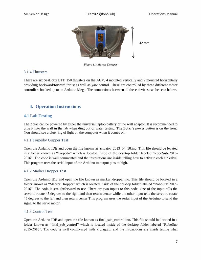
Figure 11: Marker Dropper
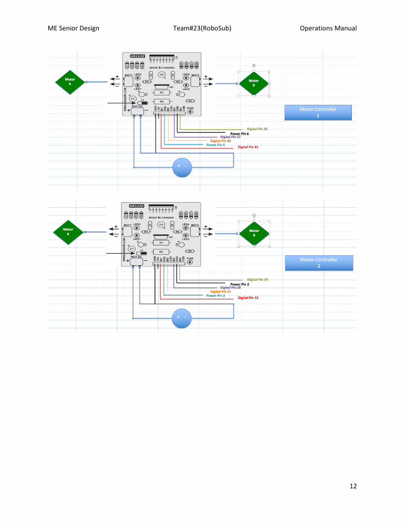
3.1.4 Thrusters
There are six SeaBotix BTD 150 thrusters on the AUV, 4 mounted vertically and 2 mounted horizontally
providing backward/forward thrust as well as yaw control. These are controlled by three different motor
controllers hooked up to an Arduino Mega. The connections between all these devices can be seen below.
4. Operation Instructions
4.1 Lab Testing
The Zotac can be powered by either the universal laptop battery or the wall adaptor. It is recommended to
plug it into the wall in the lab when ding out of water testing. The Zotac’s power button is on the front.
You should see a blue ring of light on the computer when it comes on.
4.1.1 Torpedo/ Gripper Test
Open the Arduino IDE and open the file known as actuator_2013_04_18.ino. This file should be located
in a folder known as “Torpedo” which is located inside of the desktop folder labeled “RoboSub 2015-
2016”. The code is well commented and the instructions are inside telling how to activate each air valve.
This program uses the serial input of the Arduino to output pins to high.
4.1.2 Marker Dropper Test
Open the Arduino IDE and open the file known as marker_dropper.ino. This file should be located in a
folder known as “Marker Dropper” which is located inside of the desktop folder labeled “RoboSub 2015-
2016”. The code is straightforward to use. There are two inputs to this code. One of the input tells the
servo to rotate 45 degrees to the right and then return center while the other input tells the servo to rotate
45 degrees to the left and then return center This program uses the serial input of the Arduino to send the
signal to the servo motor.
4.1.3 Control Test
Open the Arduino IDE and open the file known as final_sub_control.ino. This file should be located in a
folder known as “final_sub_control” which is located inside of the desktop folder labeled “RoboSub
2015-2016”. The code is well commented with a diagram and the instructions are inside telling what
42 mm
ME Senior Design Team#23(RoboSub) Operations Manual
8
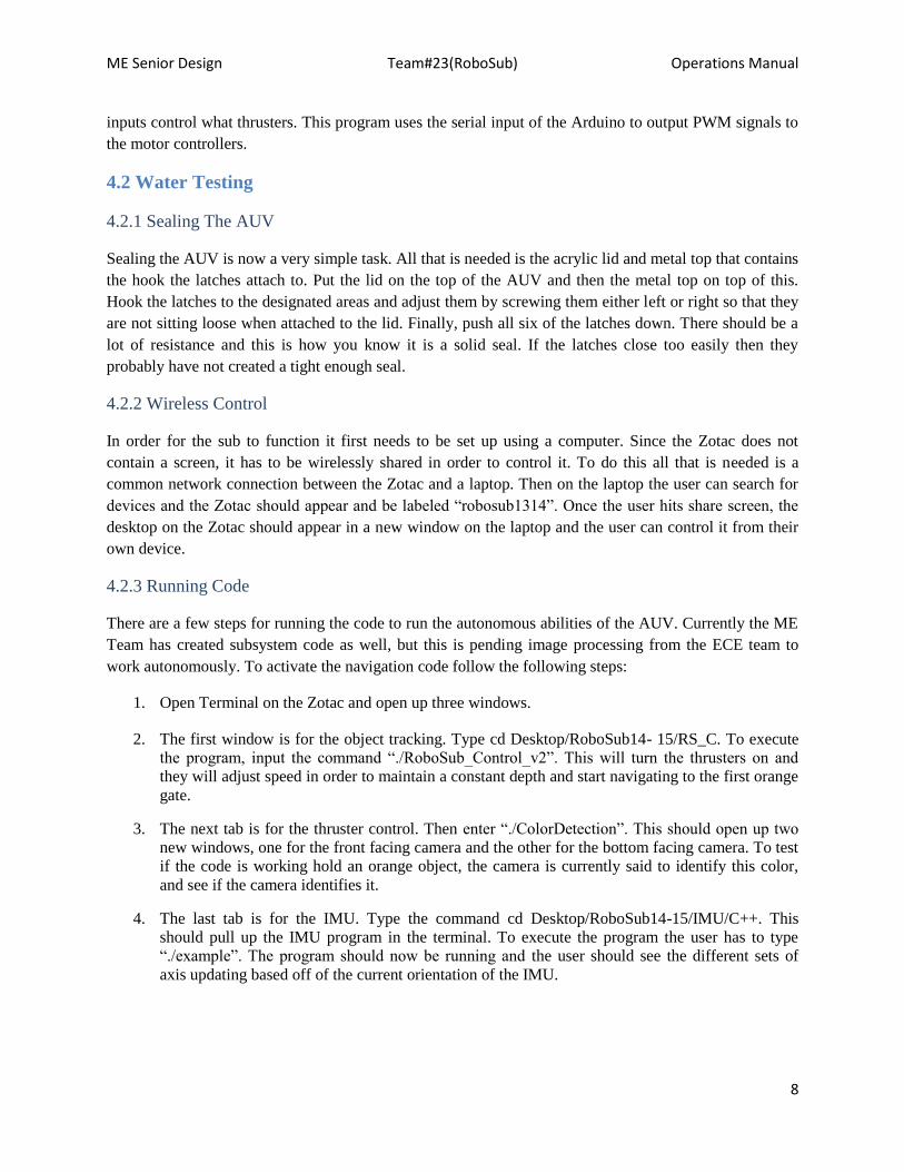
inputs control what thrusters. This program uses the serial input of the Arduino to output PWM signals to
the motor controllers.
4.2 Water Testing
4.2.1 Sealing The AUV
Sealing the AUV is now a very simple task. All that is needed is the acrylic lid and metal top that contains
the hook the latches attach to. Put the lid on the top of the AUV and then the metal top on top of this.
Hook the latches to the designated areas and adjust them by screwing them either left or right so that they
are not sitting loose when attached to the lid. Finally, push all six of the latches down. There should be a
lot of resistance and this is how you know it is a solid seal. If the latches close too easily then they
probably have not created a tight enough seal.
4.2.2 Wireless Control
In order for the sub to function it first needs to be set up using a computer. Since the Zotac does not
contain a screen, it has to be wirelessly shared in order to control it. To do this all that is needed is a
common network connection between the Zotac and a laptop. Then on the laptop the user can search for
devices and the Zotac should appear and be labeled “robosub1314”. Once the user hits share screen, the
desktop on the Zotac should appear in a new window on the laptop and the user can control it from their
own device.
4.2.3 Running Code
There are a few steps for running the code to run the autonomous abilities of the AUV. Currently the ME
Team has created subsystem code as well, but this is pending image processing from the ECE team to
work autonomously. To activate the navigation code follow the following steps:
1. Open Terminal on the Zotac and open up three windows.
2. The first window is for the object tracking. Type cd Desktop/RoboSub14- 15/RS_C. To execute
the program, input the command “./RoboSub_Control_v2”. This will turn the thrusters on and
they will adjust speed in order to maintain a constant depth and start navigating to the first orange
gate.
3. The next tab is for the thruster control. Then enter “./ColorDetection”. This should open up two
new windows, one for the front facing camera and the other for the bottom facing camera. To test
if the code is working hold an orange object, the camera is currently said to identify this color,
and see if the camera identifies it.
4. The last tab is for the IMU. Type the command cd Desktop/RoboSub14-15/IMU/C++. This
should pull up the IMU program in the terminal. To execute the program the user has to type
“./example”. The program should now be running and the user should see the different sets of
axis updating based off of the current orientation of the IMU.

ME Senior Design Team#23(RoboSub) Operations Manual
9
5. Troubleshooting
5.1 Water Leak If water leaks into the sealed hull the electronics can be permanently damaged and cause the sub
to stop working during competition. To prevent this, proper testing must be performed before placing
electronics in the hull. Furthermore absorbent material can be placed on the bottom/sides of the hull to
prevent small leaks from puddling up near electronics.
5.2 Overheating Because the hull is small and air tight conduction of heat produced by electrical components can
cause the electrical components to overheat and fail. To prevent this fans are placed in the hull to aid in
convective heat transfer. Furthermore a heat sink can be added to use the outside water to facilitate heat
transfer.
5.3 Connection Issues Due to the amount of subsystems on the hull there are many electrical connections both outside and
inside the hull. These electrical connections can be broken or malfunction through normal movement or
user error and cause the AUV to stop working. To prevent these electrical disconnections more secure
connections can be made by soldering and using clamps on the wires. Also connections could be tested
using a multimeter to ensure proper connections.
6. Regular Maintenance
6.1 Mechanical Maintenance
The moving components in the mechanical system require some form of lubrication, this includes
the solenoid valves, gripping mechanism, and latches. All seals on the hull that separate the hull internals
from the water must be checked prior to and immediately following any aquatic operation. If leakage is
noticed extra sealant should be applied to the problem area and retested. The Hull lid should be inspected
for cracks and the waterproof rubber spacer between the lid and the hull edge should be inspected for
tears prior to any pool testing.
6.2 Electrical Maintenance
The electrical components for the most part should last for many years to come. The major
components, such as the Zotac and Arduinos, should not need to be replaced unless during testing one of
them gets shorted. The same goes for the four relays as well as the voltage regulators. The only
maintenance that should need to be done should be checking to make sure all the connections are still
solid and all of the solder joints are still intact. The batteries to power the AUV will also need to be
charged.

ME Senior Design Team#23(RoboSub) Operations Manual
10
7. Spare Parts
Table 2: Parts List
Part Cost Quantity Distributor Part Number
Stainless steel McMaster-Carr
Rubber Seal $20.00 1 Steelerubber 70-1192-52
Acrylic Lid $16.83 1 McMaster-Carr 8574K28
Toggle Latches $20.93 6 J.W. Winco INC 110ENGL
Latch Catch Plate $2.98 6 Protex 03-1692SS
Cable Penetrators $4.00 12 BlueRobotics PENETRATOR-10-25-A-
R2
34” Aluminum Bar $9.77 2 8020.net 1010
8” Aluminum Bar $3.79 12 8020.net 1010
5 hole 90° bracket $6.30 4 8020.net 4151
2 hole 90° bracket $2.90 20 8020.net 4119
¼-20 x .500"
Button Head
$0.30 62 8020.net 3690
¼ - 20 T-Nut $0.61 62 8020.net 3675
2 Hole T-Nut $0.95 4 8020.net 3356
3 Hole T-Nut $1.55 4 8020.net 3358
Kill Switch $22.88 1 Oznium
8. Recommended Approach/Conclusion
8.1 Thruster Modifications Currently the sub has 5 degrees of freedom and is only missing translation in the sideways
direction. By placing and additional thruster pointing sideways the sub can navigate easier and allow it to
complete tasks more efficiently. Furthermore the thrusters on the sub are several years old and are in need
of replacement in the near future. The thrusters are about $700 therefore new thrusters should be
investigated such as the blureobotics thrusters which are recommended by competition officials.
8.2 Camera Modifications Much like the thrusters the cameras are beginning to age and will eventually need to be replaced.
The current camera housing is fairly large and could accommodate several different types of cameras. If a
more compact camera is chosen a new camera housing could be made that is smaller and produces less
buoyancy force.
8.3 Waterproofing Air Tank The air tank that it currently being used is not made for underwater use and will eventually rust.
A waterproof casing could easily be made to prevent this rusting and corrosion. Another solution would
be to find a small enough tank that is waterproof. Finally the more complex option would be to place the
tank inside the hull and drill a hole that a pipe could fit to. This may not work due to the little available
space in the hull.

ME Senior Design Team#23(RoboSub) Operations Manual
11
9. Appendix
Table 3: Spec Sheets
Component Spec Sheet
Zotac-ZBOX CI321 nano PC
https://www.zotac.com/us/product/mini_pcs/ci321-nano
Arduino Uno https://www.arduino.cc/en/Main/ArduinoBoardUno
Mega https://www.arduino.cc/en/Main/ArduinoBoardMega2560
IMU https://www.sparkfun.com/products/10736 and
https://www.sparkfun.com/products/9873
Motor Controllers https://www.sparkfun.com/products/9670
Seabotics motor
Gripper https://trimantec.com/wp-content/uploads/2015/06/catalog-for-HFY.pdf
Marker Dropper Servo
ME Senior Design Team#23(RoboSub) Operations Manual
12

ME Senior Design Team#23(RoboSub) Operations Manual
13
Figure 12: Motor Controller Wiring