Operations Guide for the HMC and Managed Systems Version 7 Release 3
114
Operations Guide for the HMC and Managed Systems Version 7 Release 3 ESCALA Power6 REFERENCE 86 A1 85FF 00
Transcript of Operations Guide for the HMC and Managed Systems Version 7 Release 3
Operations Guide for the HMC and Managed Systems Version 7 Release 3 ES
CA
LA P
ower
6
REFERENCE 86 A1 85FF 00

ESCALA Power6
Operations Guide for the HMC and Managed Systems Version 7 Release 3
HardwareApril 2008
BULL CEDOC
357 AVENUE PATTON
B.P.20845
49008 ANGERS CEDEX 01
FRANCE
REFERENCE 86 A1 85FF 00

The following copyright notice protects this book under Copyright laws which prohibit such actions as, but not limited to, copying, distributing, modifying, and making derivative works.
Copyright Bull SAS 2008
Printed in France
Suggestions and criticisms concerning the form, content, and presentation of this book are invited. A form is provided at the end of this book for this purpose.
To order additional copies of this book or other Bull Technical Publications, you are invited to use the Ordering Form also provided at the end of this book.
Trademarks and Acknowledgements
We acknowledge the right of proprietors of trademarks mentioned in this book.
The information in this document is subject to change without notice. Bull will not be liable for errors ontained herein, or for incidental or consequential damages in connection with the use of this material.
c

Contents
About this publication . . . . . . . . . . . . . . . . . . . . . . . . . . . . . viiHow to send your comments . . . . . . . . . . . . . . . . . . . . . . . . . . . . . vii
Chapter 1. Introduction to the Hardware Management Console . . . . . . . . . . . . 1User interface style for the HMC . . . . . . . . . . . . . . . . . . . . . . . . . . . . 1Predefined user IDs and passwords. . . . . . . . . . . . . . . . . . . . . . . . . . . . 1Tasks and roles . . . . . . . . . . . . . . . . . . . . . . . . . . . . . . . . . . 2Starting the HMC. . . . . . . . . . . . . . . . . . . . . . . . . . . . . . . . . . 3
Chapter 2. Using the Web-based user interface . . . . . . . . . . . . . . . . . . . 5Task bar . . . . . . . . . . . . . . . . . . . . . . . . . . . . . . . . . . . . . 5Navigation pane . . . . . . . . . . . . . . . . . . . . . . . . . . . . . . . . . . 5
Welcome. . . . . . . . . . . . . . . . . . . . . . . . . . . . . . . . . . . . 6Systems Management . . . . . . . . . . . . . . . . . . . . . . . . . . . . . . . 6
Servers . . . . . . . . . . . . . . . . . . . . . . . . . . . . . . . . . . . 6Selecting a server . . . . . . . . . . . . . . . . . . . . . . . . . . . . . . . 7Displaying server details . . . . . . . . . . . . . . . . . . . . . . . . . . . . 8Launching tasks for managed objects . . . . . . . . . . . . . . . . . . . . . . . . 8Partitions . . . . . . . . . . . . . . . . . . . . . . . . . . . . . . . . . 9Displaying partition details . . . . . . . . . . . . . . . . . . . . . . . . . . . 10
Frames . . . . . . . . . . . . . . . . . . . . . . . . . . . . . . . . . . . 10Custom Groups . . . . . . . . . . . . . . . . . . . . . . . . . . . . . . . . 10
User-defined groups . . . . . . . . . . . . . . . . . . . . . . . . . . . . . 11System Plans . . . . . . . . . . . . . . . . . . . . . . . . . . . . . . . . . . 11HMC Management . . . . . . . . . . . . . . . . . . . . . . . . . . . . . . . . 12Service Management . . . . . . . . . . . . . . . . . . . . . . . . . . . . . . . 13Updates . . . . . . . . . . . . . . . . . . . . . . . . . . . . . . . . . . . 13
Work pane. . . . . . . . . . . . . . . . . . . . . . . . . . . . . . . . . . . . 13Working with Tables . . . . . . . . . . . . . . . . . . . . . . . . . . . . . . . 13
Selecting Rows . . . . . . . . . . . . . . . . . . . . . . . . . . . . . . . . 14Filtering . . . . . . . . . . . . . . . . . . . . . . . . . . . . . . . . . . 14Sorting . . . . . . . . . . . . . . . . . . . . . . . . . . . . . . . . . . . 14Column configuration . . . . . . . . . . . . . . . . . . . . . . . . . . . . . . 14Views menu . . . . . . . . . . . . . . . . . . . . . . . . . . . . . . . . . 14
Status bar . . . . . . . . . . . . . . . . . . . . . . . . . . . . . . . . . . . . 14Status: Unacceptable . . . . . . . . . . . . . . . . . . . . . . . . . . . . . . . 15Status: Attention LEDs. . . . . . . . . . . . . . . . . . . . . . . . . . . . . . . 15Status: Serviceable Events . . . . . . . . . . . . . . . . . . . . . . . . . . . . . 15Status Overview . . . . . . . . . . . . . . . . . . . . . . . . . . . . . . . . . 15
Chapter 3. Systems Management for Servers . . . . . . . . . . . . . . . . . . . 17Properties . . . . . . . . . . . . . . . . . . . . . . . . . . . . . . . . . . . . 17Update Password . . . . . . . . . . . . . . . . . . . . . . . . . . . . . . . . . 18Operations . . . . . . . . . . . . . . . . . . . . . . . . . . . . . . . . . . . 18
Power On . . . . . . . . . . . . . . . . . . . . . . . . . . . . . . . . . . . 18Power Off . . . . . . . . . . . . . . . . . . . . . . . . . . . . . . . . . . . 19Power Management . . . . . . . . . . . . . . . . . . . . . . . . . . . . . . . 19LED Status . . . . . . . . . . . . . . . . . . . . . . . . . . . . . . . . . . 20Schedule Operations . . . . . . . . . . . . . . . . . . . . . . . . . . . . . . . 20Advanced System Management . . . . . . . . . . . . . . . . . . . . . . . . . . . 22Utilization Data . . . . . . . . . . . . . . . . . . . . . . . . . . . . . . . . . 22Rebuild. . . . . . . . . . . . . . . . . . . . . . . . . . . . . . . . . . . . 22Change Password . . . . . . . . . . . . . . . . . . . . . . . . . . . . . . . . 23
Configuration . . . . . . . . . . . . . . . . . . . . . . . . . . . . . . . . . . 23Create Logical Partition . . . . . . . . . . . . . . . . . . . . . . . . . . . . . . 23
© Copyright IBM Corp. 2007, 2008 iii

System Plans . . . . . . . . . . . . . . . . . . . . . . . . . . . . . . . . . . 23Partition Availability Priority . . . . . . . . . . . . . . . . . . . . . . . . . . . . 23View Workload Management Groups . . . . . . . . . . . . . . . . . . . . . . . . . . 24Manage Custom Groups . . . . . . . . . . . . . . . . . . . . . . . . . . . . . . 24Manage Partition Data. . . . . . . . . . . . . . . . . . . . . . . . . . . . . . . 24Manage System Profiles . . . . . . . . . . . . . . . . . . . . . . . . . . . . . . 25Virtual Resources . . . . . . . . . . . . . . . . . . . . . . . . . . . . . . . . 26
Shared processor pool management . . . . . . . . . . . . . . . . . . . . . . . . . 26Shared Memory Pool Management . . . . . . . . . . . . . . . . . . . . . . . . . . 26Virtual Storage Management. . . . . . . . . . . . . . . . . . . . . . . . . . . . . 27Virtual Network Management . . . . . . . . . . . . . . . . . . . . . . . . . . . . 27
Connections . . . . . . . . . . . . . . . . . . . . . . . . . . . . . . . . . . . 27View service processor connection status . . . . . . . . . . . . . . . . . . . . . . . . 27Resetting or removing connections . . . . . . . . . . . . . . . . . . . . . . . . . . 28Disconnecting another HMC. . . . . . . . . . . . . . . . . . . . . . . . . . . . . 28Adding a managed system . . . . . . . . . . . . . . . . . . . . . . . . . . . . . 28Correcting a connection problem . . . . . . . . . . . . . . . . . . . . . . . . . . . 28
Correcting a No connection state for a managed system . . . . . . . . . . . . . . . . . . 28Correcting an Incomplete state for a managed system . . . . . . . . . . . . . . . . . . . 29Correcting a Recovery state for a managed system . . . . . . . . . . . . . . . . . . . . 30Correcting an Error state for a managed system . . . . . . . . . . . . . . . . . . . . . 30Correcting a Failed Authentication state for a managed system . . . . . . . . . . . . . . . . 30Correcting a new connection problem between the HMC and a managed system . . . . . . . . . . 31
Hardware Information. . . . . . . . . . . . . . . . . . . . . . . . . . . . . . . . 31Adapters . . . . . . . . . . . . . . . . . . . . . . . . . . . . . . . . . . . 31
Host Channel Adapter (HCA) . . . . . . . . . . . . . . . . . . . . . . . . . . . 31Host Ethernet Adapter (HEA) . . . . . . . . . . . . . . . . . . . . . . . . . . . 32
View Hardware Topology . . . . . . . . . . . . . . . . . . . . . . . . . . . . . 32Updates . . . . . . . . . . . . . . . . . . . . . . . . . . . . . . . . . . . . 32Serviceability . . . . . . . . . . . . . . . . . . . . . . . . . . . . . . . . . . . 33
Manage Serviceable Events . . . . . . . . . . . . . . . . . . . . . . . . . . . . . 33Create Serviceable Event . . . . . . . . . . . . . . . . . . . . . . . . . . . . . . 33Reference Code History . . . . . . . . . . . . . . . . . . . . . . . . . . . . . . 34Control Panel Functions . . . . . . . . . . . . . . . . . . . . . . . . . . . . . . 34Hardware . . . . . . . . . . . . . . . . . . . . . . . . . . . . . . . . . . . 34
Add FRU . . . . . . . . . . . . . . . . . . . . . . . . . . . . . . . . . . 34Add Enclosure . . . . . . . . . . . . . . . . . . . . . . . . . . . . . . . . 34Exchange FRU . . . . . . . . . . . . . . . . . . . . . . . . . . . . . . . . 35Exchange Enclosure . . . . . . . . . . . . . . . . . . . . . . . . . . . . . . 35Remove FRU . . . . . . . . . . . . . . . . . . . . . . . . . . . . . . . . . 35Remove Enclosure . . . . . . . . . . . . . . . . . . . . . . . . . . . . . . . 35Power On/Off IO Unit . . . . . . . . . . . . . . . . . . . . . . . . . . . . . 35
Manage Dumps . . . . . . . . . . . . . . . . . . . . . . . . . . . . . . . . . 36Collect VPD . . . . . . . . . . . . . . . . . . . . . . . . . . . . . . . . . . 36Edit MTMS . . . . . . . . . . . . . . . . . . . . . . . . . . . . . . . . . . 36FSP Failover . . . . . . . . . . . . . . . . . . . . . . . . . . . . . . . . . . 37
Capacity on Demand . . . . . . . . . . . . . . . . . . . . . . . . . . . . . . . . 37
Chapter 4. Systems Management for Partitions . . . . . . . . . . . . . . . . . . 39Properties . . . . . . . . . . . . . . . . . . . . . . . . . . . . . . . . . . . . 39Change Default Profile . . . . . . . . . . . . . . . . . . . . . . . . . . . . . . . 39Operations . . . . . . . . . . . . . . . . . . . . . . . . . . . . . . . . . . . 39
Activate . . . . . . . . . . . . . . . . . . . . . . . . . . . . . . . . . . . 39Restart . . . . . . . . . . . . . . . . . . . . . . . . . . . . . . . . . . . . 40Shut Down . . . . . . . . . . . . . . . . . . . . . . . . . . . . . . . . . . 40Manage Attention LED . . . . . . . . . . . . . . . . . . . . . . . . . . . . . . 41Schedule Operations . . . . . . . . . . . . . . . . . . . . . . . . . . . . . . . 41viosvrcmd . . . . . . . . . . . . . . . . . . . . . . . . . . . . . . . . . . . 42Delete . . . . . . . . . . . . . . . . . . . . . . . . . . . . . . . . . . . . 43Mobility . . . . . . . . . . . . . . . . . . . . . . . . . . . . . . . . . . . 43
Migrate. . . . . . . . . . . . . . . . . . . . . . . . . . . . . . . . . . . 43
iv Operations Guide for the HMC and Managed Systems

Validate . . . . . . . . . . . . . . . . . . . . . . . . . . . . . . . . . . 43Recover. . . . . . . . . . . . . . . . . . . . . . . . . . . . . . . . . . . 44
Configuration . . . . . . . . . . . . . . . . . . . . . . . . . . . . . . . . . . 44Manage Profiles . . . . . . . . . . . . . . . . . . . . . . . . . . . . . . . . . 44Manage Custom Groups . . . . . . . . . . . . . . . . . . . . . . . . . . . . . . 44Save Current Configuration . . . . . . . . . . . . . . . . . . . . . . . . . . . . . 44
Hardware Information. . . . . . . . . . . . . . . . . . . . . . . . . . . . . . . . 45Adapters . . . . . . . . . . . . . . . . . . . . . . . . . . . . . . . . . . . 45
Host Ethernet Adapter (HEA) . . . . . . . . . . . . . . . . . . . . . . . . . . . 45Host Channel Adapter (HCA) . . . . . . . . . . . . . . . . . . . . . . . . . . . 45Switch Network Interface. . . . . . . . . . . . . . . . . . . . . . . . . . . . . 45
Virtual IO Adapters . . . . . . . . . . . . . . . . . . . . . . . . . . . . . . . 45Dynamic Logical Partitioning . . . . . . . . . . . . . . . . . . . . . . . . . . . . . 46
Processor . . . . . . . . . . . . . . . . . . . . . . . . . . . . . . . . . . . 46Memory . . . . . . . . . . . . . . . . . . . . . . . . . . . . . . . . . . . 46Physical Adapters . . . . . . . . . . . . . . . . . . . . . . . . . . . . . . . . 46Virtual Adapter . . . . . . . . . . . . . . . . . . . . . . . . . . . . . . . . . 47Host Ethernet. . . . . . . . . . . . . . . . . . . . . . . . . . . . . . . . . . 47
Console window . . . . . . . . . . . . . . . . . . . . . . . . . . . . . . . . . 48Serviceability . . . . . . . . . . . . . . . . . . . . . . . . . . . . . . . . . . . 48
Manage Serviceable Events . . . . . . . . . . . . . . . . . . . . . . . . . . . . . 48Reference Code History . . . . . . . . . . . . . . . . . . . . . . . . . . . . . . 49Control Panel Functions . . . . . . . . . . . . . . . . . . . . . . . . . . . . . . 49
Chapter 5. Systems Management for Frames . . . . . . . . . . . . . . . . . . . 51Properties . . . . . . . . . . . . . . . . . . . . . . . . . . . . . . . . . . . . 51Update Password . . . . . . . . . . . . . . . . . . . . . . . . . . . . . . . . . 51Operations . . . . . . . . . . . . . . . . . . . . . . . . . . . . . . . . . . . 52
Initialize Frames . . . . . . . . . . . . . . . . . . . . . . . . . . . . . . . . . 52Initialize All Frames . . . . . . . . . . . . . . . . . . . . . . . . . . . . . . . 52Rebuild. . . . . . . . . . . . . . . . . . . . . . . . . . . . . . . . . . . . 52Change Password . . . . . . . . . . . . . . . . . . . . . . . . . . . . . . . . 52Power On/Off IO Unit . . . . . . . . . . . . . . . . . . . . . . . . . . . . . . 52
Configuration . . . . . . . . . . . . . . . . . . . . . . . . . . . . . . . . . . 52Manage Custom Groups . . . . . . . . . . . . . . . . . . . . . . . . . . . . . . 53
Connections . . . . . . . . . . . . . . . . . . . . . . . . . . . . . . . . . . . 53Bulk Power Assembly (BPA) Status . . . . . . . . . . . . . . . . . . . . . . . . . . 53Reset . . . . . . . . . . . . . . . . . . . . . . . . . . . . . . . . . . . . 54
Hardware Information. . . . . . . . . . . . . . . . . . . . . . . . . . . . . . . . 54View RIO Topology. . . . . . . . . . . . . . . . . . . . . . . . . . . . . . . . 54
Serviceability . . . . . . . . . . . . . . . . . . . . . . . . . . . . . . . . . . . 54Manage Serviceable Events . . . . . . . . . . . . . . . . . . . . . . . . . . . . . 54Hardware . . . . . . . . . . . . . . . . . . . . . . . . . . . . . . . . . . . 55
Add FRU . . . . . . . . . . . . . . . . . . . . . . . . . . . . . . . . . . 55Add Enclosure . . . . . . . . . . . . . . . . . . . . . . . . . . . . . . . . 55Exchange FRU . . . . . . . . . . . . . . . . . . . . . . . . . . . . . . . . 56Exchange Enclosure . . . . . . . . . . . . . . . . . . . . . . . . . . . . . . 56Remove FRU . . . . . . . . . . . . . . . . . . . . . . . . . . . . . . . . . 56Remove Enclosure . . . . . . . . . . . . . . . . . . . . . . . . . . . . . . . 56
Chapter 6. System Plans . . . . . . . . . . . . . . . . . . . . . . . . . . . . 57View System Plan . . . . . . . . . . . . . . . . . . . . . . . . . . . . . . . . . 57Create System Plan . . . . . . . . . . . . . . . . . . . . . . . . . . . . . . . . . 57Deploy System Plan . . . . . . . . . . . . . . . . . . . . . . . . . . . . . . . . 58Export System Plan. . . . . . . . . . . . . . . . . . . . . . . . . . . . . . . . . 58Import System Plan . . . . . . . . . . . . . . . . . . . . . . . . . . . . . . . . 58Remove System Plan . . . . . . . . . . . . . . . . . . . . . . . . . . . . . . . . 59
Chapter 7. Updates . . . . . . . . . . . . . . . . . . . . . . . . . . . . . . 61Update HMC . . . . . . . . . . . . . . . . . . . . . . . . . . . . . . . . . . . 61
Contents v

Managed System Updates . . . . . . . . . . . . . . . . . . . . . . . . . . . . . . 61Change Licensed Internal Code for the current release . . . . . . . . . . . . . . . . . . . . 62Upgrade Licensed Internal Code to a new release . . . . . . . . . . . . . . . . . . . . . 63Flash Side Selection. . . . . . . . . . . . . . . . . . . . . . . . . . . . . . . . 64Check system readiness . . . . . . . . . . . . . . . . . . . . . . . . . . . . . . 64View system information . . . . . . . . . . . . . . . . . . . . . . . . . . . . . . 64
Appendix A. HMC tasks, user roles, IDs, and associated commands . . . . . . . . . 65
Appendix B. Remote operations . . . . . . . . . . . . . . . . . . . . . . . . . 89Using a remote HMC . . . . . . . . . . . . . . . . . . . . . . . . . . . . . . . . 89Using a Web browser . . . . . . . . . . . . . . . . . . . . . . . . . . . . . . . . 90Using the HMC remote command line . . . . . . . . . . . . . . . . . . . . . . . . . . 91
Setting up secure script execution between SSH clients and the HMC . . . . . . . . . . . . . . . 91Enabling and disabling HMC remote commands . . . . . . . . . . . . . . . . . . . . . . 92
Web browser requirements . . . . . . . . . . . . . . . . . . . . . . . . . . . . . . 92Preparing to use the Web browser . . . . . . . . . . . . . . . . . . . . . . . . . . . . 92Logging in to the HMC from a LAN-connected Web browser. . . . . . . . . . . . . . . . . . . 92
Appendix C. Customizable data replication . . . . . . . . . . . . . . . . . . . . 95Peer-to-Peer replication . . . . . . . . . . . . . . . . . . . . . . . . . . . . . . . 95Master-to-Slave replication . . . . . . . . . . . . . . . . . . . . . . . . . . . . . . 96Data replication . . . . . . . . . . . . . . . . . . . . . . . . . . . . . . . . . . 97
Appendix D. HMC commands . . . . . . . . . . . . . . . . . . . . . . . . . . 99
Notices . . . . . . . . . . . . . . . . . . . . . . . . . . . . . . . . . . . 101Trademarks . . . . . . . . . . . . . . . . . . . . . . . . . . . . . . . . . . . 102Terms and conditions. . . . . . . . . . . . . . . . . . . . . . . . . . . . . . . . 102
vi Operations Guide for the HMC and Managed Systems

About this publication
This publication helps users to understand how to use the Hardware Management Console (HMC),describes the tasks you can use on the console, and how to navigate using the web-based user interface.
Note: The HMC user interface windows represented in this document are general samples. They may ormay not represent the exact windows that are displayed for your user ID or version.
For information about the accessibility features of this product, for users who have a physical disability,see accessibledoc.dita.
How to send your commentsYour feedback is important in helping to provide the most accurate and highest quality information. Ifyou have any comments about this publication, use the Feedback button at http://www.ibm.com/systems/infocenter. Alternatively, you can send your comments to [email protected]. Be sure toinclude the name of the book, the form number of the book, and the specific location of the text you arecommenting on (for example, a page number or table number).
© Copyright IBM Corp. 2007, 2008 vii

viii Operations Guide for the HMC and Managed Systems

Chapter 1. Introduction to the Hardware Management Console
This section briefly describes some of the concepts and functions of the Hardware Management Console(HMC) and introduces the user interface that is used for accessing those functions.
The HMC is a system that controls managed systems, logical partitions, Capacity on Demand (CoD), andupdates. To provide flexibility and availability, you can implement HMCs as a local HMC or a redundantHMC.
Local HMCA local HMC is an HMC that is physically located close to the system it manages and isconnected by either a private or public network. An HMC in a private network is a DHCP serverfor the service processors of the systems it manages. An HMC may also manage a system over anopen network, where the managed system’s service processor IP address has been assignedmanually using the Advanced System Management Interface (ASMI).
Remote HMCA remote HMC is an HMC that is not physically located near its managed systems. This could bein another part of the same room or data center, in another building, or even on another site.Typically, a remote HMC would be attached to its managed servers via a public network, butconfigurations with a remote HMC attached to a private network are also possible. Prior to HMCversion 7, at least one local HMC was required. With Version 7, any or all HMCs may be remote.
Redundant HMCA redundant HMC manages a system that is already managed by another HMC. When twoHMCs manage one system, they are peers, and each can be used to control the managed system.One HMC can manage multiple managed systems, and each managed system can have twoHMCs. If both HMCs are connected to the server using private networks, each HMC must be aDHCP server set up to provide IP addresses on two unique, nonroutable IP ranges.
The HMC allows you to configure and manage servers. One HMC can manage multiple servers, and dualHMCs can provide redundant support by managing the same system. To help ensure consistent function,each HMC is shipped preinstalled with the Hardware Management Console Licensed Machine CodeVersion 7.
User interface style for the HMCThis HMC uses a Web-based user interface. This interface uses a tree style navigation model providinghierarchical views of system resources and tasks to enable direct access to hardware resources and taskmanagement capabilities. It provides views of system resources and provides tasks for systemadministration.
See Chapter 2, “Using the Web-based user interface,” on page 5 for detailed information on how to usethis HMC interface.
Predefined user IDs and passwordsPredefined user IDs and passwords are included with the HMC. It is imperative to your system’s securitythat you change the hscroot predefined password immediately.
© Copyright IBM Corp. 2007, 2008 1

The following predefined user IDs and passwords are included with the HMC:
Table 1. Predefined HMC user IDs and passwords
User ID Password Purpose
hscroot abc123 The hscroot user ID and passwordare used to log in to the HMC for thefirst time. They are case-sensitive andcan only be used by a member of thesuper administrator role.
root passw0rd The root user ID and password areused by the service provider toperform maintenance procedures.They cannot be used to log in to theHMC.
Tasks and rolesEach HMC user can be a member of a different role. Each of these roles allows the user to access differentparts of the HMC and perform different tasks on the managed system. HMC roles are either predefinedor customized.
The roles discussed in this section refer to HMC users; operating systems running on logical partitionshave their own set of users and roles. When you create an HMC user, you must assign that user a taskrole. Each task role allows the user varying levels of access to tasks available on the HMC interface. Formore information about the tasks each HMC user role can perform, see Appendix A, “HMC tasks, userroles, IDs, and associated commands,” on page 65.
You can assign managed systems and logical partitions to individual HMC users. This allows you tocreate a user that has access to managed system A but not to managed system B. Each grouping ofmanaged resource access is called a managed resource role. To learn more about managed resource rolesand how to create them, see Manage Task and Resource Roles.
The predefined HMC roles, which are the default on the HMC, are as follows:
Table 2. Predefined HMC Roles
Role Description HMC User ID
Operator The operator is responsible for dailysystem operation.
hmcoperator
Super Administrator The super administrator acts as theroot user, or manager, of the HMCsystem. The super administrator hasunrestricted authority to access andmodify most of the HMC system.
hmcsuperadmin
Product Engineer A product engineer assists in supportsituations, but cannot access HMCuser management functions. Toprovide support access for yoursystem, you must create andadminister user IDs with the productengineer role.
hmcpe
Service Representative A service representative is anemployee who is at your location toinstall, configure, or repair thesystem.
hmcservicerep
2 Operations Guide for the HMC and Managed Systems

Table 2. Predefined HMC Roles (continued)
Role Description HMC User ID
Viewer A viewer can view HMC information,but cannot change any configurationinformation.
hmcviewer
You can create customized HMC roles by modifying predefined HMC roles. Creating customized HMCroles is useful for restricting or granting specific task privileges to a certain user. For more informationabout creating customized HMC roles, see Manage Task and Resource Roles.
Starting the HMCTurn on the HMC by setting both the display and system unit to the On position. The initializationwindow, which includes the copyright information, is displayed. Learn about how to log in to the HMCinterface.
When initialization is complete, the pre-login window is displayed.
Note: The pre-login window contains the link to log in to the HMC application, the ability to view theonline help information, and the summarized status information for the HMC. You will need to log in toview the status information.
To log in to the HMC do the following:1. In the pre-login window, click Log on and launch the Hardware Management Console web
application.2. Enter the user ID and password combination assigned to you.3. Click Logon.
Note: If you previously disconnected from your session, the Choose a Disconnected Session windowopens. Select the session you want to reconnect to and click Reconnect.
After you log in, the HMC workplace window opens and, if enabled, the Tip of the Day windowappears. For more information about how to enable this feature, see Tip of the Day.
The HMC workplace window allows you to work with tasks for your console and managed systems. Notall tasks are available for each user ID. The user role assigned to your user ID determines what tasks youare able to perform. For example, if you are assigned a user ID with the operator role, you will haveaccess to all the tasks that have operator access. See Appendix A, “HMC tasks, user roles, IDs, andassociated commands,” on page 65 for a listing of all tasks and the user roles for which the tasks areavailable.
If at any time you do not know or remember what user ID you are currently logged in to the HMC, lookat the task bar on the top of the Welcome page or you can click HMC Management in the navigationpane. Then click Manage Users and Tasks from the work pane (see Manage Users and Tasks for moreinformation).
Chapter 1. Introduction to the Hardware Management Console 3

4 Operations Guide for the HMC and Managed Systems

Chapter 2. Using the Web-based user interface
You can use the Web-based user interface to perform tasks on the Hardware Management Console(HMC) or on your managed resources.
This user interface comprises several major components: the banner, the task bar, the navigation pane, thework pane, and the status bar.
The banner, across the top of the workplace window, identifies the product and logo. It is optionallydisplayed. Use the Change User Interface Settings task to change the setting.
The task bar, located below the banner, displays the names of any tasks that are running, the user ID youare logged in as, online help information, and the ability to logoff or disconnect from the console.
The navigation pane, in the left portion of the window, contains the primary navigation links for managingyour system resources and the HMC. The items are referred to as nodes.
The work pane, in the right portion of the window, displays information based on the current selectionfrom the navigation pane. For example, when Welcome is selected in the navigation pane, the Welcomewindow content is displayed in the work pane.
The status bar, in the bottom left portion of the window, provides visual indicators of current overallsystem status. It also contains a status overview icon which may be selected to display more detailedstatus information in the work pane.
You can resize the panes of the HMC workplace by moving the mouse pointer over the border thatseparates the navigation pane from the work pane until the mouse pointer changes to a double-pointedarrow. When the pointer changes shape, press and hold the left mouse button while dragging the mousepointer to the left or right. Release the button and your navigation pane or work pane is now larger orsmaller in size. You can also do this within the work pane border that separates the resources table fromthe tasks pad.
Task barThe Task bar contains the Help and Logoff tasks and a button that represents each currently running task.
Navigation paneThe Navigation pane contains the primary links for managing your system resources and the HMC.These include Systems Management, System Plans, HMC Management, and Service Management.
Systems Management
Systems Management contains a view of system resources such as servers, frames, and Custom groups.Custom groups include the predefined groups ’All Partitions’, ’All Objects’, and any user-defined groups.
System Plans
System Plans contains plans to deploy and manage the HMC on a managed system.
© Copyright IBM Corp. 2007, 2008 5

HMC Management
HMC Management contains categorized HMC management tasks. Related tasks are categorizedalphabetically by links including HMC and user customization, console tasks, connectivity, and settings.
Service Management
Service Management contains a categorized or alphabetic view of tasks and their descriptions used toservice the Hardware Management Console.
Updates
Updates provides a way for you to access information on both HMC and system firmware code levels atthe same time without running a task.
WelcomeWelcome is the initial window that is displayed when you log on to the HMC.
The Welcome work pane lists the nodes of the navigation pane and their descriptions. It also includes thefollowing Additional Resources:
Guided Setup WizardProvides a step-by-step process to configure your HMC.
HMC Operations GuideProvides an online version of the Managing the HMC for system administrators and systemoperators using the HMC.
If you are accessing the HMC remotely, you can view the publication in PDF format or in HTMLformat (click View as HTML). If you are accessing the HMC locally, you can view the publicationin HTML format.
HMC ReadmeProvides hints and errata information about the HMC.
Online InformationProvides information about the HMC.
Note: The following information is only available when you are accessing the HMC remotely.
IBM® System Supportsupplies support and technical information for IBM Systems
HMC Supportsupplies support and technical information for the HMC
Education and Tutorialssupplies course materials for training and updating HMC skills
To see what level of the HMC you are currently using, point your mouse over HMC Version at the topof the work pane.
Systems ManagementSystems Management contains a tree view of managed resources. Resources may include Servers, Frames,and Custom Groups.
ServersServers represents the servers that are managed by this HMC.
6 Operations Guide for the HMC and Managed Systems
To add servers, you can use the Add Managed System task under the Connections category in the taskspad.
When you click Servers from the navigation pane a listing of individually defined servers is displayed intable form in the work pane, and under the Servers node in the navigation pane.
Selecting a server:
Learn about the information displayed when you select a server.
To work with a server, you can perform one of the following actions:v Select a server under the Servers node from the navigation pane.v Click on a server name from the work pane table.v Click in the Select column next to the server name in the work pane table.
The Servers work pane table displays the following attributes by default.
Name Specifies the user-defined name of the managed system.
Status Displays the current status of the managed system (for example, Operating, Power off,Initializing) and, in addition, displays icons representing an unacceptable state or an activeAttention LED. See “Status: Unacceptable” on page 15 or “Status: Attention LEDs” on page 15 formore information.
Available Processing UnitsDisplays the number of processing units that are available for assignment to logical partitions onthe managed system. This is the total number of processing units that are activated on themanaged system minus the number of processing units that are assigned to the logical partitions,including the logical partitions that are shut down, on the managed system. This number doesnot include any processing units that have not yet been activated with Capacity on Demand(CoD).
Available MemoryDisplays the amount of memory that is available for assignment to logical partitions on themanaged system. This is the total amount of memory that is activated on the managed systemminus the amount of memory needed by managed system firmware minus the amount ofmemory that is assigned to the logical partitions, including the logical partitions that are shutdown, on the managed system. This number does not include any memory that has not yet beenactivated with Capacity on Demand (CoD). The available memory amount can be shown in MBor GB. Click MB or GB in the Available Memory column title.
Reference CodeDisplays the system reference codes for the server. Click the reference code in the table for adetailed description.
The Servers work pane table can also display the following optional attributes in the table.
Configurable Processing UnitsDisplays the configured processing units. Configured - Licensed and usable (not guarded)processing units.
Configurable MemoryDisplays the configured memory. Configured - Licensed and usable (not guarded) memory.
Serial NumberDisplays the serial number of the managed system.
Type-ModelDisplays the type and model number of the managed system (for example, 9117-MMA).
Chapter 2. Using the Web-based user interface 7

CoD Processor CapableDisplays whether the managed system supports Capacity on Demand (CoD) for processors.
CoD Memory CapableDisplays whether the managed system supports CoD for memory.
Permanent ProcessorsSpecifies the number of permanent licensed processors.
On/Off CoD Processors StateDisplays the On/Off CoD processor state.
Trial CoD Processor StateDisplays the Trial CoD processor state.
Reserved CoD Processor StateDisplays the Reserved CoD processor state.
Utility CoD Processor StateDisplays the Utility CoD processor state.
Permanent Memory (GB)Displays the amount of permanent activated memory.
On/Off CoD Memory StateDisplays the On/Off CoD memory state.
Trial CoD Memory StateDisplays the Trial CoD memory state.
To show optional attributes, select the Column configuration icon on the table toolbar. This functionallows you to select additional attributes that you want displayed as columns in the table. It also allowsyou to reorder the columns, see “Column configuration” on page 14 for more information.
You can also use Views from the table toolbar to display the Default server attributes in the table or todisplay the Capacity On Demand server attributes in the table. See “Views menu” on page 14 for moreinformation.
Displaying server details:
Display a server’s properties.
To display details (properties) about a server, you can select the server by clicking in the Select column inthe work pane table. Then you can either click Properties from the tasks pad or click on thedouble-arrow icon next to the server name and click Properties from the context menu. In both cases, theProperties window opens.
Launching tasks for managed objects:
After you have chosen the objects to work with, you are ready to perform the appropriate tasks on them.Learn about how to launch a task for your selected managed objects.
Appropriate tasks for a selected object are listed in the tasks pad, in context menus, and in the Tasksmenu.If a particular task cannot be performed on an object, the task will not display.
Tasks pad:
The Tasks pad appears below the Work pane when you have selected an object you want to work with.This view contains available tasks for selected managed object(s).
The tasks contained in this view meet the following characteristics:
8 Operations Guide for the HMC and Managed Systems

v Tasks are available for the currently selected target object(s) in the Navigation pane tree or the Workpane table view. If multiple objects are selected in the Work pane table, the intersection of the selectedobjects’ tasks is displayed. If there are no selections in the table, tasks are displayed for the objectselected in the Navigation pane.
v Tasks available are limited by the role of the currently logged in user
The Tasks pad is optionally displayed and is set by using the Change User Interface Settings task.
The following is an example of using the Tasks pad method:1. In the Work pane table, select a server.2. In the Tasks pad, select a task group by clicking on the expand button or clicking on the group name.3. Select a task that appears under the task group that you want to perform on that server. The task
window opens.
Context Menu:
The Context menu lists the task groups appropriate for the selected object. Context menus are availableonly for table selections. For example, in the Select column of the Servers Work pane table, select theobject you want to work with. The Context menu button (double right arrows) appears next to the objectname you have selected. Click the button and the task groups menu appears for that particular object.Then select a task. If more than one object is selected, the tasks that appear in the Context menu(s) applyto all selections.
Tasks menu:
The tasks menu is displayed on the table toolbar.
The tasks menu is available only for table selections. For example, in the Select column of the Serverswork pane table, select the object you want to work with. Click Tasks for the list of the applicable taskgroups for the selected objects in the table. Select a task group, then select a task to open for the object. Ifmore than one object is selected, the tasks that are displayed in the tasks menu apply to all selections.
Partitions:
When you select a managed server in the navigation pane, the work pane displays the list of partitionsdefined on the server.
The Partitions work pane table displays the following attributes by default:
Name Specifies the user-defined name of the logical partition.
ID Specifies the ID of the partition
Status Displays the current status of the partition (for example, running, not activated) and, in addition,displays icons representing an unacceptable state or active Attention LED. See “Status:Unacceptable” on page 15 or “Status: Attention LEDs” on page 15 for more information.
Processing UnitsDisplays the unit of measure for shared processing power across one or more virtual processors.Processing power can be specified in fractions of a processor.
MemorySpecifies the amount of memory allocated to the partition currently. The memory amount can beshown in MB or GB. Click MB or GB in the Memory column title.
Active ProfileSpecifies the profile that was used to activate the partition last.
Chapter 2. Using the Web-based user interface 9
EnvironmentSpecifies the type of object, logical partition, server, frame.
Reference CodeDisplays the system reference codes for the partition. For POWER6® systems, click the referencecode in the table for a detailed description.
The Partitions work pane table can also display the following optional attributes in the table.
ProcessorIf the partition is using dedicated processors, this value indicates the number of processorscurrently allocated to the partition. If the partition is using shared processors, this valuerepresents the virtual processors currently allocated to the partition.
Service PartitionSpecifies whether the partition has service authority.
ConfiguredSpecifies whether a partition is configured with all the required resources to power on.
Default ProfileSpecifies the profile that is configured as the default profile. When users perform the Activatetask from the partition, this profile is selected by default.
Optional attributes can be displayed when you select the Column configuration icon on the table toolbar.This function allows you to select additional attributes that you want displayed as columns in the table.It also allows you to reorder the columns, see “Column configuration” on page 14 for more information.
Displaying partition details:
Display a partition’s properties.
To display details (properties) about a partition you can select the partition by clicking in the Selectcolumn in the work pane table. Then you can either click Properties from the tasks pad or click on thedouble-arrow icon next to the partition name and click Properties from the context menu. You can alsoclick on the partition name. In all cases the Properties window is displayed.
FramesThe Frames node identifies the frames managed by this HMC.
Frames typically have dual Bulk Power Controllers (BPCs), however only one BPC is displayed as bothBPCs share the same machine type, model, and serial number and function as redundant peers.
The Frames work pane table includes the following attributes:
Name Displays the defined name of the Frame.
Status Displays the status of the frame object. A frame is in an unacceptable state when it is in NoConnection or Incomplete state. When either of these conditions occurs, a red X is displayed inthe status cells next to the status text which identifies the state. Clicking on either the X or thestatus text opens information describing the unacceptable state and potential remedies.
Frame NumberDisplays the number of the managed frame. You can modify the number.
Connection StatusDisplays connection status of the frame (side A and B).
Custom GroupsThe Custom Groups node provides a mechanism for you to group system resources together in a singleview.
10 Operations Guide for the HMC and Managed Systems

Groups may be nested to create custom ″topologies″ of system resources.
Custom groups include the predefined groups All Partitions and All Objects and any user-definedgroups that you created using the Manage Custom Groups task under the Configuration category in thetasks pad. The All Partitions group includes all the partitions defined to all servers managed by theHMC. The All Objects group is a collection of all the managed servers, partitions, and frames.
These system-defined groups (All Partitions and All Objects) cannot be deleted. However, if you do notwant All Partitions or All Objects displayed under Custom Groups, do the following:1. Open the Change User Interface Settings task from the HMC Management work pane.2. Deselect All Partitions node and All Objects node in the User Interface Settings window.3. Click OK to save the changes and close the window. Those groups are no longer displayed under
Custom Groups in the navigation pane.
You can use the Views menu on the table toolbar to display your preferred table column configuration.For more information, see “Views menu” on page 14.
User-defined groups:
Create new groups and manage existing ones.
Click Manage Custom Groups task under the Configuration category from the tasks pad to create yourown group that you want to work with.
To create a group, do the following:1. Select one or more resources (for example: servers, partitions, frames) that you want to include in the
group you want to work with.2. Click Manage Custom Groups.3. Select Create a new group, specify a group name and description, and then click OK. The new
user-defined group is displayed in the navigation pane under Custom Groups.
You can also create a group by using the pattern match method. To use the pattern match method, do thefollowing:1. Without selecting an object, click Manage Custom Groups from the Custom Groups or Systems
Management tasks pad.2. From the Create Pattern Match Group window, select one or more group types that you want to
create, specify a group name, description, and the pattern used to determine if an object should bepart of the group. Click OK to complete. The new user-defined group is displayed in the navigationpane under the Custom Groups node.
Note: Patterns specified in the Managed Resource Pattern input field are regular expressions. Forexample, if you specified abc.*, all the resources that begin with abc will be included in that group.
For more information, see “Manage Custom Groups” on page 24.
System PlansYou can display the plans and the tasks used to deploy system plans to managed systems.
A system plan contains a specification of the logical partition configuration of a single managed system.You can also use this node to import, export, and manage the files containing these system plans.
To display the plans and tasks:1. In the navigation pane, select System Plans.2. In the work pane, select a plan you want to work with by clicking in the Select column.
Chapter 2. Using the Web-based user interface 11

3. From the tasks pad, click one of the following tasks:v Create System Planv Deploy System Planv Export System Planv Import System Planv Remove System Planv View System Plan
These tasks are described in further detail in “System Plans” on page 23. The table in the work panedisplays the system plans that the HMC manages and attributes related to the system plans.
The following attributes are set as the defaults. However, you can select or deselect the attributes thatyou want displayed in the table by clicking the Column configuration icon on the table toolbar. You canalso reorder the columns. For more information, see “Column configuration” on page 14.
Name Displays the system plan file name.
DescriptionSpecifies a description of the system plan.
SourceDisplays how the system plan was created.
VersionDisplays version information about the system plan.
Last Modified DateSpecifies the date when the system plan was last modified.
The create and deploy System Plans tasks are also displayed for a server under the Configuration taskgroup.
If there are no system plans available when you select System Plans, you can create or import a planfrom the tasks listed in the tasks pad.
HMC ManagementHMC Management contains a categorized view of HMC management tasks and their descriptions.
These tasks are used for setting up the HMC, maintaining its internal code, and securing the HMC.
To display the tasks in the work pane, do the following:1. In the Navigation pane, select HMC Management .2. In the work pane, click on the task you want to perform.3. By default, a categorized listing of the tasks is displayed. The categories include:
v Operationsv Administration
To see the HMC level you are using, point your mouse over HMC Version at the top of the work pane.
If you want an alphabetic listing of the tasks, click Alphabetical List in the upper right corner of thework pane. Click Categorized List to go back to the task categories.
Note: If you are accessing the HMC remotely, some tasks do not display.
HMC Management tasks are described in further detail in HMC Management tasks and a listing of thetasks and the default user roles that can use them are shown in Table 4 on page 65.
12 Operations Guide for the HMC and Managed Systems
Service ManagementService Management contains a categorized or alphabetic view of tasks and their descriptions used toservice the HMC.
To display the tasks in the work pane, do the following:1. In the Navigation pane, select Service Management.2. In the work pane, click on the task you want to perform.3. By default, a categorized listing of the tasks appear. The category is Connectivity.
To see the HMC level you are using, point your mouse over HMC Version at the top of the work pane.
If you want an alphabetical listing of the tasks, click Alphabetical List in the upper right corner of thework pane. Click Categorized List to go back to the task categories.
Service Management tasks are described in further detail in Service Management tasks and a listing ofthe tasks and the default user roles that can use them are shown in Table 4 on page 65.
UpdatesUpdates provides a way for you to access information on both HMC and system firmware code levels atthe same time without performing a task.
The Updates work pane displays the HMC code level, and system code levels. You can also installcorrective service by clicking Update HMC.
Note: Before performing HMC updates, see “Update HMC” on page 61.
To display the tasks, do the following:1. In the navigation pane, select Updates.2. Select a managed object.3. In the tasks pad, click the task you want to perform.
These tasks can also be viewed under the Updates task group when you are working with managedobjects displayed inSystems Management.
Work paneThe Work pane displays information based on the current selection in the Navigation pane or Status bar.For example, when you click an individual server, the Navigation pane displays a configurable table inthe Work pane that displays a list of all the managed systems on that server.
Task pad
Selecting a task can be done in a number of ways. Tasks for selected objects are listed in the Work pane,Tasks pad, context menus, and in the Tasks drop-down menu on the table toolbar. When context sensitivetasks are listed at the bottom of the Work pane in the Tasks pad, only tasks applicable for selected objectsare displayed.
Working with TablesThe tool bar at the top of the table contains buttons used to select, filter, sort, and arrange the entries inthe table.
Hovering over the toolbar buttons displays their functions. The toolbar also includes menus that are usedwith the information displayed in the tables. For more information, see “Tasks menu” on page 9 and“Views menu” on page 14.
Chapter 2. Using the Web-based user interface 13
Selecting RowsYou can select more than one table row at a time.
Rows can be individually selected or a block of rows can be selected at once by first left-clicking theselection box of the first row in the desired block and then shift-clicking the selection box of the last rowin the desired block. The Select All or Deselect All buttons can be used to select or deselect all objects inthe table. The table summary at the bottom of the table includes the total number of items that areselected.
FilteringLearn more about how to define a filter for a column to limit the entries displayed in a table.
If you select the Filter Row button a row appears under the title row of the table. Select Filter under acolumn to define a filter for that column to limit the entries in a table. Tables can be filtered to show onlythose entries most important to you. The filtered view can be toggled on and off by selecting the checkbox next to the desired filter in the filter row. Select the Clear All Filters button to return to the completelisting. The table summary includes the total number of items that pass the filter criteria in addition tothe total number of items.
SortingThe Edit Sort and Clear All Sorts buttons are used to perform multi-column sorts of objects in the table inascending or descending order.
Click Edit Sort to define sorts for columns in a table. Alternatively, single column sorting can beperformed by selecting the ^ in the column header to change from ascending to descending order. ClickClear All Sorts to return to the default ordering.
Column configurationThe column configuration buttons give you the ability to select which columns to display for folders inthe Systems Management tree view.
Click the Configure Columns button to arrange the columns in the table in a desired order or hidecolumns from view. All available columns are listed in the Columns list box by their column name. Youselect the columns you want displayed or hidden by checking or unchecking the box next to the columnnames. The column order is manipulated by clicking on a column name from the list box and using thearrow buttons to the right of the list to change the order of the selected column. When you havecompleted the configuration of the columns, click OK. The columns appear in the table as you specified.If you want to go back to the original layout of the table, click the Reset Column Order, Visibility, andWidths button from the table toolbar. Select one or more of the properties you want to reset. Click OK tosave this setting.
Views menuThe Views menu is displayed on the toolbar and is only available for table selections when working withservers, custom groups, exceptions view, or attention LEDs view.
This table option allows you to display different sets of attributes (columns) in the table. You can alsochange the attributes for each view.
Status barThe status bar in the bottom left pane provides a view of overall system status, including managedsystem resources and the HMC.
A status-sensitive title, background color, and indicator icons are part of the status bar. The statusindicators appear in color when one or more objects go into unacceptable status, have attention LEDs, orhave open serviceable events. Otherwise, the status icon is not available.
14 Operations Guide for the HMC and Managed Systems

Click any of the individual icons in the status bar to view a listing of resources with specific status. Forexample, select the Unacceptable icon to view all resources in an unacceptable state. The results aredisplayed in a table in the work pane.
Status: UnacceptableIf any managed object is in unacceptable state, the Unacceptable indicator displays on the status bar.
When you select the Unacceptable indicator, it displays a table in the work pane of only the objects in anunacceptable state. By clicking on the icon, help information is opened describing the status of the serveror partition. You can also use the Views menu to display your preferred table column configuration forthese objects.
Status: Attention LEDsIf any managed object’s Attention LED is activated, the Attention LED icon displays in the status bar.
When you select the Attention LED icon it displays a table in the work pane of only the objects inAttention LED. A help window opens when you click on the icon. You can also use the Views menu todisplay your preferred table column configuration for these objects.
Status: Serviceable EventsIf at least one serviceable event for the HMC or a managed object is in an open state, the serviceableevent icon displays in the status bar.
When you click the icon the Manage Serviceable Events window opens. This window displays all openevents.
Status OverviewThe Status Overview icon displays a detailed summary of system status in the work pane.
The Status Overview icon displays details about any errors, attention LEDs active, or open serviceableevents found for the HMC or managed objects. It also summarizes the total number of errors, attentionLEDs, and open serviceable events by object type. Object types include the server, partition, frames, andthe HMC. When any of these conditions are present, links are available to display all objects with theparticular state in the work pane.
Chapter 2. Using the Web-based user interface 15

16 Operations Guide for the HMC and Managed Systems

Chapter 3. Systems Management for Servers
Systems Management displays tasks to manage servers, logical partitions, and frames. Use these tasks toset up, configure, view current status, troubleshoot, and apply solutions for servers.
To perform these tasks, see “Launching tasks for managed objects” on page 8. The tasks listed in thetasks pad change as selections are made in the work area. The context is always listed at the top of thetasks pad in the format Task: Object. These tasks are listed when a managed system is selected.
PropertiesDisplay the selected managed system’s properties. This information is useful in system and partitionplanning and resource allocation.
These properties include the following:
GeneralThe General tab displays the system’s name, serial number, model and type, state, attention ledstate, service processor version, maximum number of partitions, assigned service partition (ifdesignated), and power off policy information.
ProcessorThe Processor tab displays information about the managed system’s processors includinginstalled processing units, deconfigured processing units, available processing units, configurableprocessing units, minimum number of processing units per virtual processor and maximumnumber of shared processor pools.
MemoryThe Memory tab displays information about the managed system’s memory including installedmemory, deconfigured memory, available memory, configurable memory, memory region size,current memory available for partition usage, and system firmware current memory. A tabdescribes the maximum number of memory pools.
I/O The I/O tab displays the physical I/O resources for the managed system. The assignment of I/Oslots and partition and adaptor-type information are displayed, grouped by units. Select the linkin the Slot column to display the physical I/O properties of each resource. Select I/O Pools todisplay all of the I/O pools found in the system and the partitions that are participating in thepools.
MigrationIf your managed system is partition-migration capable, the Migration tab displays partitionmigration information.
Power-On ParametersThe Power-On Parameters tab displays the initial program load (IPL) source mode for restarting,and allows you to change the power-on parameters for the next restart by changing the values inthe Next fields. These changes will only be valid for the next managed system restart.
CapabilitiesThe Capabilities tab displays the runtime capabilities of this server. Select Help for moreinformation on the capabilities listed.
AdvancedThe Advanced tab displays huge page memory capabilities on the managed system, includingavailable huge page memory, configurable huge page memory, current page size, and currentmaximum huge page memory. To change memory allocation on systems with huge page tablesupport, set the Requested huge page memory (in pages) field to the desired memory. To change
© Copyright IBM Corp. 2007, 2008 17
the requested value for huge page memory, the system must be powered off. The BarrierSynchronization Register (BSR) displays array information.
Update PasswordUse the Update Password task to update HMC access and Advanced System Management Interface(ASMI) passwords on the managed system.
The first time you access a managed system using an HMC, the system prompts you to enter passwordsfor each of the following:v Hardware Management Console: HMC accessv Advanced System Management Interface: Generalv Advanced System Management Interface: Admin
If you are using an HMC to access the managed system before all required passwords have been set,enter the appropriate password for each password that is presented in the Update Password task.
If another HMC subsequently needs access to this managed system, upon attempting to access this HMCthe user is presented with the Update Password Failed Authentication window, which will prompt forthe HMC access password you entered.
In the event that the HMC access password changes while you are logged in to the managed system,your HMC will discover that it can no longer authenticate after it attempts to reconnect to that managedsystem. This will result in a state of Failed Authentication for that managed system. You will be required toenter the new password before any actions can be performed.
OperationsOperations contains the tasks for operating managed systems.
Power OnUse the Power On task to start a managed system.
Choose from the following options to power on your managed system:
Normal: Select this option to specify that the HMC uses the current setting for the partition start policy todetermine how to power on the managed system. The current setting can be one of the following values:v Auto-Start Always: This option specifies that the HMC power on logical partitions automatically after
the managed system powers on. If powering on the managed system is the result of a user action, theHMC starts all partitions that are configured for automatic start up. If powering on the managedsystem is the result of an automatic recovery process, the HMC starts only those logical partitions thatwere running at the time the system powered off. This option is always available for selection.
v Stop at Partition Standby: This option specifies that logical partition start up is in standby mode afterthe managed system powers on and the HMC does not start any logical partitions when the managedsystem powers on. If powering on the managed system is the result of an automatic recovery processand the HMC is used to start a logical partition, the HMC starts all logical partitions that were runningat the time the system powered off. This option is available for selection only when the firmware forthe managed system does not support advanced IPL capabilities.
v Auto-Start for Auto-Recovery: This option specifies that the HMC power on logical partitionsautomatically only after the managed system powers on as the result of an automatic recovery process.This option is available for selection only when the firmware for the managed system supports thisadvanced IPL capability.
18 Operations Guide for the HMC and Managed Systems

v User-Initiated: This option specifies that the HMC does not start any logical partitions when themanaged system powers on. You must start logical partitions manually on the managed system byusing the HMC. This option is available for selection only when the firmware for the managed systemsupports this advanced IPL capability.
You can set the partition start policy from the Power On Parameters page of the Properties task for themanaged system.
System profile: Selecting this power-on option specifies that the HMC power on the system and itslogical partitions based on a predefined system profile. When you select this power-on option, you mustselect the partition profile that you want the HMC to use to activate logical partitions on the managedsystem.
Hardware Discovery: Selecting this power-on option specifies that the HMC run the hardware discoveryprocess when the managed system powers on. The hardware discovery process captures informationabout all I/O devices -- in particular those devices not currently assigned to partitions. When you selectthe hardware discovery power on option for a managed system, the managed system is powered on intoa special mode which performs the hardware discovery. After the Hardware Discovery process iscomplete, the system will be in Operating state with any partitions in the power-off state. The HardwareDiscovery process records the hardware inventory in a cache on the managed system. The collectedinformation is then available for use when displaying data for I/O devices or when creating a systemplan based on the managed system. This option is available only if the system is capable of using thehardware discovery process to capture I/O hardware inventory for the managed system.
Power OffShut down the managed system. Powering off the managed system will make all partitions unavailableuntil the system is again powered on.
Before you power off the managed system, ensure that all logical partitions have been shut down andthat their states have changed from Running to Not Activated. For more information on shutting down alogical partition, see “Shut Down” on page 40
If you do not shut down all logical partitions on the managed system before you power off the managedsystem, the managed system shuts down each logical partition before the managed system itself powersoff. This can cause a substantial delay in powering off the managed system, particularly if the logicalpartitions are not responsive. Further, the logical partitions might shut down abnormally, which couldresult in data loss and further delays when you activate the logical partitions once more.
Choose from the following options:
Normal power offThe Normal power off mode shuts down the system’s operations in a controlled manner. Duringthe shutdown, programs running active jobs are allowed to perform cleanup (end-of-jobprocessing).
Fast power offThe Fast power off mode shuts down the system by stopping all active jobs immediately. Theprograms running those jobs are not allowed to perform any cleanup. Use this option when youneed to shut down the system because of an urgent or critical situation.
Power ManagementYou can reduce the manage system’s processor power consumption by enabling power saver mode.
To enable power saver mode, do the following:1. In the navigation area, expand Systems management.
Chapter 3. Systems Management for Servers 19

2. In the navigation area, expand Servers.3. Select the server that you want to enable to use power saver mode.4. In the tasks area, expand Operations.5. Click Power Management.6. Select your desired power saver mode, and click OK.
LED StatusView system attention LED information, light specific LEDs to identify a system component, and test allLEDs on a managed system.
The system provides several LEDs that help identify various components, such as enclosures or fieldreplaceable units (FRUs), in the system. For this reason, they are called Identify LEDs. Individual LEDs arelocated on or near the components. The LEDs are located either on the component itself or on the carrierof the component (for example, memory card, fan, memory module, or processor). LEDs are either greenor amber. Green LEDs indicate either of the following:v Electrical power is present.v Activity is occurring on a link. (The system could be sending or receiving information.)
Amber LEDs indicate a fault or identify condition. If your system or one of the components on yoursystem has an amber LED turned on or blinking, identify the problem and take the appropriate action torestore the system to normal.
You can activate or deactivate the following types of identify LEDs:
Identify LED for an enclosureIf you want to add an adapter to a specific drawer (enclosure), you need to know the machinetype, model, and serial number (MTMS) of the drawer. To determine whether you have thecorrect MTMS for the drawer that needs the new adapter, you can activate the LED for a drawerand verify that the MTMS corresponds to the drawer that requires the new adapter.
Identify LED for a FRU associated with a specified enclosureIf you want to attach a cable to a specific I/O adapter, you can activate the LED for the adapterthat is a field replaceable unit (FRU), and then physically verify where to attach the cable. Thiscan be especially useful when you have several adapters with open ports.
You can deactivate a system attention LED or a logical partition LED. For example, you might determinethat a problem is not a high priority and decide to repair the problem at a later time. However, you wantto be alerted if another problem occurs, so you must deactivate the system attention LED so that it can beactivated again if another problem occurs.
Choose from the following options:
Identify LEDDisplays the current Identify LED states for all the location codes contained in the selectedenclosure. From this task, you can select a single location code or multiple location codes tooperate against and activate or deactivate the LED(s) by selecting the corresponding button.
Test LEDInitiates an LED Lamp Test against the selected system. All LEDs will activate for severalminutes.
Schedule OperationsCreate a schedule for certain operations to be performed on the managed system without operatorassistance.
20 Operations Guide for the HMC and Managed Systems

Scheduled operations are helpful for situations where automatic, delayed, or repetitious processing ofsystem operations is necessary. A scheduled operation is started at a specified time, without operatorassistance to perform the operation. A schedule can be set for one operation or repeated many times.
For example, you could schedule power on or off operations for a managed system.
The Scheduled Operations task displays the following information for each operation:v The processor that is the object of the operation.v The scheduled datev The scheduled timev The operationv The number of remaining repetitions
From the Scheduled Operations window you can do the following:v Schedule an operation to run at a later timev Define operations to repeat at regular intervalsv Delete a previously scheduled operationv View details for a currently scheduled operationv View scheduled operations within a specified time rangev Sort scheduled operations by date, operation, or managed system
You can schedule an operation to occur once or you can schedule it to repeat. You must provide the timeand date that you want the operation to occur. If the you want the operation to repeat, you will be askedto select the following:v The day or days of the week that you want the operation to occur. (optional)v The interval, or time between each occurrence. (required)v The total number of repetitions. (required)
The operations that you can schedule for the managed system include the following:
Activate on a System ProfileSchedules an operation on a selected system for scheduling activation of a selected system profile.
Backup Profile DataSchedules an operation to back up profile data for a managed system
Power Off Managed SystemSchedules an operation for a system power off at regular intervals for a managed system.
Power On Managed SystemSchedules an operation for a system power on at regular intervals for a managed system.
Manage Utility CoD processorsSchedules an operation for managing how your Utility CoD processors are used.
Manage Utility CoD processor minute usage limitCreates a limit for Utility CoD processor usage.
Modify a Shared Processor PoolSchedules an operation for modifying a shared processor pool.
Move a partition to a different poolSchedules an operation for moving a partition to a different processor pool.
Change power saver mode on a managed systemSchedules an operation for changing a managed system’s power saver mode.
To schedule operations on the managed system, do the following:1. In the Navigation area, click Systems Management.2. In the Navigation area, click Servers.
Chapter 3. Systems Management for Servers 21

3. In the work pane, select one or more managed systems.4. In the tasks pad, select the Operations task category, then click Schedule Operations. The Customize
Scheduled Operations window opens.5. From the Customize Scheduled Operations window, click Options from the menu bar to display the
next level of options:v To add a scheduled operation, click Options and then click New....v To delete a scheduled operation, select the operation you want to delete, point to Options and then
click Delete.v To update the list of scheduled operations with the current schedules for the selected objects, point
to Options and then click Refresh.v To view a scheduled operation, select the operation you want to view, point to View and then click
Schedule Details....v To change the time of a scheduled operation, select the operation you want to view, point to View
and then click New Time Range....v To sort the scheduled operations, point to Sort and then click one of the sort categories that
appears.6. To return to the HMC workplace, point to Operations and then click Exit.
Advanced System ManagementThe HMC can connect directly to the Advanced System Management (ASM) interface for a selectedsystem.
ASM is an interface to the service processor that allows you to manage the operation of the server, suchas auto power restart, and to view information about the server, such as the error log and vital productdata.
To connect to the Advanced System Management interface, do the following:1. From the System Management tasks list, select Operations.2. From the Operations task list, select Advanced System Management (ASM).
Utilization DataYou can set the HMC to collect resource utilization data for a specific managed system or for all systemsthe HMC manages.
The HMC collects utilization data for memory and processor resources. You can use this data to analyzetrends and make resource adjustments. The data is collected into records called events. Events are createdat the following times:v At periodic intervals (30 seconds, 1 minute, 5 minutes, 30 minutes, hourly, daily, and monthly)v When you make system-level and partition-level state and configuration changes that affect resource
utilizationv When you start up, shut down, and change the local time on the HMC
You must set the HMC to collect utilization data for a managed system before utilization data can displayfor the managed system.
Use the Change Sampling Rate task to enable, set and change the sampling rate, or disable samplingcollection.
RebuildYou can extract the configuration information from the managed system and rebuild the information onthe Hardware Management Console (HMC).
22 Operations Guide for the HMC and Managed Systems

This task does not disrupt the operation of the running server.
Rebuilding the managed system updates the information on the HMC about the managed system.Rebuilding the managed system is useful when the state of the managed system is Incomplete. TheIncomplete state means that the HMC cannot gather complete information from the managed systemabout logical partitions, profiles, or resources.
Rebuilding the managed system is different from refreshing the HMC window. When the managedsystem is rebuilt, the HMC extracts the information from the managed system. You cannot start othertasks while the HMC rebuilds the managed system. This process can take several minutes.
Change PasswordChange the HMC access password on the selected managed system
After the password is changed, you must update the HMC access password for all other HMCs fromwhich you want to access this managed system.
Enter the current password. Then enter a new password and verify it by entering it again.
ConfigurationConfiguration contains the tasks for configuring your managed system and partitions.
Create Logical PartitionAccess the LPAR Wizard to create a new logical partition (LPAR) on your managed system.
Ensure you have logical partition planning information before you use this wizard. Logical partitionplanning information can be found at the System Planning Tool (SPT) Web site: http://www.ibm.com/systems/support/tools/systemplanningtool/. The SPT is available to assist you in system planning,design, validation and to provide a system validation report that reflects your system requirements whilenot exceeding system recommendations.
For more information about creating logical partitions, see Logical Partitioning.
System PlansRecord or import specifications for logical partitions, partition profiles, or hardware specifications on achosen system.
A system plan is a specification of the logical partition configuration of a single managed system. A systemplan is stored in a file that is called a system-plan file and has a file suffix of .sysplan. A system-plan filecan contain more than one system plan, although multiple plans in a single file are not common.
The System Plans tasks creates a record of the hardware and partition configuration of a managedsystem at a given time. It records specifications for the logical partitions and partition profiles on theselected system. It can also record hardware specifications that the HMC is able to detect.
To maximize the information that the HMC can obtain from the managed system, power on the managedsystem and activate the logical partitions on the managed system before creating the new system plan.
The System Plans tasks are the same tasks that are available from the System Plans node from thenavigation pane and are documented here: Chapter 6, “System Plans,” on page 57.
Partition Availability PriorityUse this task to specify the partition-availability priority of each logical partition on this managed system.
Chapter 3. Systems Management for Servers 23

The managed system uses partition-availability priorities in the case of processor failure. If a processorfails on a logical partition, and there are no unassigned processors available on the managed system, thelogical partition can acquire a replacement processor from logical partitions with a lowerpartition-availability priority. This allows the logical partition with the higher partition-availabilitypriority to continue running after a processor failure.
You can change the partition availability priority for a partition by selecting a partition and choosing anavailability priority from those listed.
Use the online Help if you need additional information about prioritizing partitions.
View Workload Management GroupsDisplay a detailed view of the workload management groups you have specified for this managedsystem.
Each group displays the total number of processors, processing units for partitions using shared modeprocessing, and the total amount of memory allocated to the partitions in the group.
Manage Custom GroupsYou can report status on a group basis, allowing you to monitor your system in a way that you prefer.
You can also nest groups (a group contained within a group) to provide hierarchical or topology views.
One or more user-defined groups might already be defined on your HMC. Default groups are listedunder Custom Groups node under Server Management. The default groups are All Partitions and AllObjects. You can create others, delete the ones that were created, add to created groups, create groupsusing the pattern match method, or delete from created groups by using the Manage Custom Groupstask.
Use the online Help if you need additional information for working with groups.
Manage Partition DataA partition profile is a record on the HMC that specifies a possible configuration for a logical partition.When you activate a partition profile, the managed system attempts to start the logical partition using theconfiguration information in the partition profile.
A partition profile specifies the desired system resources for the logical partition and the minimum andmaximum amounts of system resources that the logical partition can have. The system resources specifiedwithin a partition profile includes processors, memory, and I/O resources. The partition profile can alsospecify certain operating settings for the logical partition. For example, you can set a partition profile sothat, when the partition profile is activated, the logical partition is set to start automatically the next timethat you power on the managed system.
Each logical partition on a managed system that is managed by an HMC has at least one partition profile.You can create additional partition profiles with different resource specifications for your logical partition.If you create multiple partition profiles, you can designate any partition profile on the logical partition tobe the default partition profile. The HMC activates the default profile if you do not select a specificpartition profile to be activated. Only one partition profile can be active at one time. To activate anotherpartition profile for a logical partition, you must shut down the logical partition before you activate theother partition profile.
A partition profile is identified by partition ID and profile name. Partition IDs are whole numbers used toidentify each logical partition that you create on a managed system, and profile names identify thepartition profiles that you create for each logical partition. Each partition profile on a logical partition
24 Operations Guide for the HMC and Managed Systems

must have a unique profile name, but you can use a profile name for different logical partitions on asingle managed system. For example, logical partition 1 cannot have more than one partition profile witha profile name of normal, but you can create a profile named normal for each logical partition on themanaged system.
When you create a partition profile, the HMC shows you all of the resources available on your system.The HMC does not verify if another partition profile is currently using a portion of these resources.Therefore, it is possible for you to overcommit resources. When you activate a profile, the systemattempts to allocate the resources that you assigned to the profile. If you have overcommitted resources,the partition profile will not be activated.
For example, you have four processors on your managed system. Partition 1 profile A has threeprocessors, and partition 2 profile B has two processors. If you attempt to activate both of these partitionprofiles at the same time, partition 2 profile B will fail to activate because you have overcommittedprocessor resources.
When you shut down a logical partition and reactivate the logical partition using a partition profile, thepartition profile overlays the resource specifications of the logical partition with the resourcespecifications in the partition profile. Any resource changes that you made to the logical partition usingdynamic logical partitioning are lost when you reactivate the logical partition using a partition profile.This is desirable when you want to undo dynamic logical partitioning changes to the logical partition.However, this is not desirable if you want to reactivate the logical partition using the resourcespecifications that the logical partition had when you shut down the managed system. Therefore, keepyour partition profiles up to date with the latest resource specifications. You can save the currentconfiguration of the logical partition as a partition profile. This allows you to avoid having to changepartition profiles manually.
If you shut down a logical partition whose partition profiles are not up to date, and the logical partitionis set to start automatically when the managed system starts, you can preserve the resource specificationson that logical partition by restarting the entire managed system using the partition autostart power-onmode. When the logical partitions start automatically, the logical partitions have the resourcespecifications that the logical partitions had when you shut down the managed system.
Use the Manage Partition Data tasks to do the following:v Restore partition data. If you lose partition profile data, use the restore task in one of three ways:
– Restore partition data from a backup file. Profile modifications performed after the selected backupfile was created will be lost.
– Restore merged data from your backup file and recent profile activity. The data in the backup filetakes priority over recent profile activity if the information conflicts.
– Restore merged data from recent profile activity and your backup file. The data from recent profileactivity takes priority over your backup file if the information conflicts.
v Initialize partition data. Initializing the partition data for a managed system will delete all of thecurrently defined system profiles, partitions, and partition profiles.
v Backup a partition profile to a file.v Backup partition data to a file.
Use the online Help if you need additional information about managing partition data.
Manage System ProfilesA system profile is an ordered list of partition profiles that is used by the HMC to start the logicalpartitions on a managed system in a specific configuration.
Chapter 3. Systems Management for Servers 25

When you activate the system profile, the managed system attempts to activate each partition profile inthe system profile in the order specified. A system profile helps you activate or change the managedsystem from one complete set of logical partition configurations to another.
You can create a system profile that has a partition profile that has overcommitted resources. You can usethe HMC to validate the system profile against the currently available system resources and against thetotal system resources. Validating your system profile ensures that your I/O devices and processingresources are not overcommitted, and it increases the likelihood that the system profile can be activated.The validation process estimates the amount of memory needed to activate all of the partition profiles inthe system profile. It is possible that a system profile can pass validation and yet not have enoughmemory to be activated.
Use this task to do the following:v Create new system profiles.v Create a copy of a system profile.v Validate the resources specified in the system profile against the resources available on the managed
system. The validation process indicates whether any of the logical partitions in the system profile arealready active and whether the uncommitted resources on the managed system can meet the minimumresources specified in the partition profile.
v View the properties of a system profile. From this task, you can view or change an existing systemprofile.
v Delete a system profile.v Activate a system profile. When you activate a system profile, the managed system will attempt to
activate the partition profiles in the order specified in the system profile.
Use the online Help if you need additional information about managing system profiles.
Virtual ResourcesManage shared processor pools, shared memory pools, virtual storage, and virtual networks.
Shared processor pool managementYou can assign a specific amount of the processing capacity in a shared processor pool to each logicalpartition that uses shared processors.
Shared processors are physical processors whose processing capacity is shared among multiple logicalpartitions. By default, all physical processors that are not dedicated to specific logical partitions aregrouped together in a shared processor pool. This task allows you to view information about your sharedprocessor pool and to make changes to that pool.
Detailed information about configuring shared processor pools is available. For more information, seeConfiguring shared processor pools using the HMC version 7 release 3.2.0, or later.
Shared Memory Pool ManagementUse the Create/Modify Shared Memory Pool wizard to configure a shared memory pool.
The Create/Modify Shared Memory Pool wizard is only available when the managed system supportsthe use of Active Memory Sharing. Active Memory Sharing is a feature that enables you to assign physicalmemory to a shared memory pool and share that memory among multiple logical partitions.
To create or modify a shared memory pool between partitions, do the following:1. In the Navigation area, click Systems Management.2. In the Navigation area, click Servers.3. In the work pane, select one or more managed systems.
26 Operations Guide for the HMC and Managed Systems

4. In the tasks pad, select the Operations task category, then click Virtual Resources.5. Click Shared Memory Pool Management. The Create/Modify Shared Memory Pool wizard opens.6. Complete the steps in the wizard to perform your task.
Virtual Storage ManagementYou can create and manage the virtual disks, storage pools, physical volumes, and optical devices in yourmanaged system using the Virtual Storage Management task.
A single storage pool is created automatically when you install Virtual I/O Server. This storage pool isusually called rootvg.
To manage the storage capability of your managed system, do the following:1. In the Navigation area, click Systems Management.2. In the Navigation area, click Servers.3. In the work pane, select one or more managed systems.4. In the contents area, select the VIOS partition for which you want to manage storage details.5. In the tasks pad, select the Operations task category, then click Virtual Resources.6. Click Virtual Storage Management.
Virtual Network ManagementYou can view the state of all the virtual networks on the managed system using the Virtual NetworkManagement task.
To view information about the virtual networks on the managed system, do the following:1. In the Navigation area, click Systems Management.2. In the Navigation area, click Servers.3. In the work pane, select one or more managed systems.4. In the tasks pad, select the Operations task category, then click Virtual Resources.5. Click Virtual Network Management.
ConnectionsYou can view the HMC connection status to service processors or frames, reset those connections, connectanother HMC to the selected managed system, or disconnect another HMC.
If you have selected a managed system in the work area, the following tasks pertain to that managedsystem. If you have selected a frame, the tasks pertain to that frame.
View service processor connection statusView information about the status of the HMC connection to the service processors on the managedsystem.
To show the service processor connection status to the service processors on the managed system, do thefollowing:1. In the navigation area, expand Systems management.2. In the navigation area, expand Servers.3. Select the server for which you want to view service processor connection status.4. In the tasks area, expand Connections.5. Select Service Processor Status.
Chapter 3. Systems Management for Servers 27

Resetting or removing connectionsReset or remove a managed system from the HMC interface.
To reset or remove connections, do the following:1. In the navigation area, expand Systems management.2. In the navigation area, expand Servers.3. Select the server that you want to reset or remove.4. In the tasks area, expand Connections.5. Select Reset or Remove Connections.6. Select an option and click OK.
Disconnecting another HMCYou can disconnect a connection between a selected HMC and the managed server.
To disconnect another HMC, do the following:1. In the navigation area, expand Systems management.2. In the navigation area, expand Servers.3. Select the server for which you want to disconnect another HMC.4. In the tasks area, expand Connections.5. Select Disconnect another HMC.6. Select an HMC from the list and click OK.
Adding a managed systemAdd systems in the network to the list of systems managed by this HMC.
To add managed systems in the network to the list of systems managed by this HMC, do the following:1. In the navigation area, expand Systems management.2. In the navigation area, expand Servers.3. Select the server.4. In the tasks area, expand Connections.5. Select Add Managed System.6. Select an option, enter the required IP address information, and click OK.
Correcting a connection problemTo correct a connection problem between the HMC and the managed system or to correct the state of amanaged system in No Connection, Incomplete, Recovery, Error, or Failed Authentication state, follow theprocedures below.
Correcting a No connection state for a managed systemThe No connection state can occur when the HMC is not connected, or the handshake with the managedsystem failed.
Use this procedure for a system that was previously connected to the same HMC and is now in Noconnection state. If you have a new system, a new HMC, or have moved your system to a differentHMC, refer to Correcting a connection problem between the HMC and a managed system.1. From the Systems Management - Servers work pane, select the managed system.2. Select Connections - Service Processor Status. Record the IP address of the service processor.3. From the HMC Management work pane, select Test Network Connectivity.4. Enter the IP address of the service processor and select Ping.
28 Operations Guide for the HMC and Managed Systems

5. Choose from the following options:v If the ping is successful, go to step 6.v If the ping is not successful, go to step 7.
6. If the ping test is successful, perform the following steps:a. In the Systems Management - Servers work pane, ensure that there are no reference codes
displayed in the Reference Code column for the server in No Connection state. Note: A steadyreference code could indicate a hardware problem. If the reference code is a clickable link, click thereference code to display possible procedures to correct the problem. If the reference code is not alink or a solution is not presented, contact your next level of support or your hardware serviceprovider.
b. Restart the HMC. For more information on restarting the HMC, see Shut Down or Restart.c. If restarting the HMC does not resolve the problem, contact your next level of support or your
hardware service provider.7. If the ping test is not successful, perform the following steps:
a. In the Systems Management - Servers work pane, ensure that there are no reference codesdisplayed in the Reference Code column for the server in No Connection state. Note: A steadyreference code could indicate a hardware problem. If the reference code is a clickable link, click thereference code to display possible procedures to correct the problem. If the reference code is not alink or a solution is not presented, contact your next level of support or your hardware serviceprovider.
b. If your system has a control panel, check to see if the power light is on. Choose from thefollowing options:v If there is power to the managed system, go to step 8.v If there is no power to the managed system, “Power On” on page 18 the managed system. After
the power is restored, wait 5 minutes for the service processor to re-IPL and the HMC tore-establish contact. If the system is equipped with redundant service processors, allow up to 20minutes for this step.
8. Verify physical network connectivity:a. Verify that the HMC and the service processor are correctly connected to your Ethernet network.b. Verify that Ethernet link status is good on all network segments which exist between the HMC
and the managed system.c. If you think the network might be the problem, connect a cable from the HMC to the service
processor and try pinging the failing system. Then choose from the following options:v If the ping is successful, put the cables back the way they were and correct the network
problem. After the network problem is resolved, repeat this entire procedure.v If the ping is not successful, put the cables back the way they were and continue with step 8.d.
d. Reset the service processor using the following steps:1) “Power Off” on page 19 the server.2) Unplug the AC power cord and re-plug it back in.3) “Power On” on page 18 the server.
9. If the problem is not resolved by any of the above steps, contact your next level of support or yourhardware service provider.
Correcting an Incomplete state for a managed systemThe Incomplete state can occur when the HMC failed to get all of the necessary information from themanaged system.
To correct an Incomplete state, perform the following steps:1. From the Systems Management - Servers work pane, select the managed system.2. In the tasks pad, select Operations - Rebuild.
Chapter 3. Systems Management for Servers 29

3. Select Yes to refresh the internal representation of the managed system on the HMC.v If the state remains Incomplete, rebuild the managed system several more timesv If the state goes to Recovery, see “Correcting a Recovery state for a managed system.”v If the state remains in Incomplete or goes to Recovery, continue with the next step.
4. In the tasks pad, select Connections - Reset or Remove Connections to reset the connection from themanaged system to the HMC. If this fails, continue to the next step.
5. Restart the HMC. For more information on restarting the HMC, see Shut Down or Restart.v If the state goes to Recovery, see “Correcting a Recovery state for a managed system.”v If the state remains Incomplete, perform the following steps:
– Verify that there is a redundant HMC.– Verify that no one is entering commands from the alternate HMC.– Repeat step 1 through 5. If it still fails, continue with the next step.
6. If the problem persists, contact your next level of support or your hardware service provider.
Correcting a Recovery state for a managed systemThe Recovery state can occur when the save area in the service processor assembly is not synchronizedwith the HMC.
To recover from the Recovery state, perform the following steps:1. Restore partition data. For details, see the Recover task in “Manage Partition Data” on page 24. If this
solves the problem, this ends the procedure.2. If the problem is not resolved after restoring partition data, choose the option that describes what
happened:v If the state remains Recovery, retry restoring partition data. If it fails a second time, follow the
problem determination procedure for any reference codes you receive.v If the state changed to Incomplete, refer to “Correcting an Incomplete state for a managed system”
on page 29.v If the state changed to No Connection, refer to “Correcting a No connection state for a managed
system” on page 28.3. If the problem persists, contact your next level of support or your hardware service provider.
Correcting an Error state for a managed systemThe Error state automatically generates a call to the service support center if the function is enabled.
If the automatic call support function is not enabled, contact your next level of support or your hardwareservice provider.
Correcting a Failed Authentication state for a managed systemThe Failed Authentication state can occur when the HMC access password for the managed system isnot valid.1. Do you have an HMC password?
v Yes: Enter the HMC password and choose from the following options:– If the managed system goes to Operating, Power Off, or Standby state, the authentication was
successful. This ends the procedure.– If the managed system goes to No connection, Incomplete, Recovery, or Error state, refer to
Correcting the managed system operating state.v No: Do you have an ASMI admin password?
– Yes: Continue with step 2.– No: Contact your next level of support to request CE login. Then continue with step 2, using CE
login instead of admin password for step 2.a.
30 Operations Guide for the HMC and Managed Systems

2. Perform the following steps:a. Login to the ASMI with admin authority. See “Advanced System Management” on page 22.b. Select Login Profile.c. Select Change Password.d. In the User ID to change field, select HMC.e. Enter the ASMI’s admin password in the Current password for user ID admin field. Note: Do not
enter the HMC user password.f. Enter the ASMI’s admin password.g. Enter a new HMC access password twice and click Continue.h. From the Systems Management - Servers work pane, select the managed system.i. Select Update password.j. Input the new password that was set in step 2.g. This ends the procedure.
Correcting a new connection problem between the HMC and a managed systemUse this procedure if you have a new HMC, a new managed system, or have moved your managedsystem to a different HMC.
If your system was previously connected to the same HMC and is now in No connection state, refer to“Correcting a No connection state for a managed system” on page 28.1. From the Systems Management - Servers work pane, select Connections - Add Managed System
from the tasks pad. For more information, see “Connections” on page 27. Does the system appear inthe work pane?v Yes: This ends the procedure.v No: Continue with step 2.
2. Check for network problems, cables, switches, link lights on the service processor, and so on. Wasthere a problem?v Yes: Correct the problem and return to step 1.v No: Continue with step 3.
3. Reset the service processor to force it to request a new IP address using the following steps:a. “Power Off” on page 19 the server.b. Unplug the AC power cord and re-plug it back in.c. “Power On” on page 18 the server.
4. Did resetting the service processor resolve the problem?v Yes: This ends the procedure.v No: Contact your next level of support.
Hardware InformationDisplay information about the hardware attached to a selected managed system.
AdaptersView information about the Host Ethernet Adapters (HEA, also referred to as Integrated Virtual Ethernetadapters) or Host Channel Adapters (HCA) for a selected managed system.
For more information about HEAs, see Host Ethernet Adapter.
Host Channel Adapter (HCA)Host Channel Adapters (HCAs) provide a managed system with port connections to other devices. Thatport can be connected to another HCA, a target device, or a switch that redirects the data coming in onone of its ports out to a device attached to another of its ports.
Chapter 3. Systems Management for Servers 31

You can show a list of the HCAs for the managed system. You can select an HCA from the list to displaythe current partition usage for the HCA.
From this task you can display the following:v The physical location of each HCA on the managed system.v The number of globally unique identifiers (GUIDs) that are in use on each HCA.v The number of GUIDs on each HCA that are available to be assigned to logical partitions.v HMC management status. HCAs that are unable to be managed by an HMC are in an error state.v The logical partition usage for a selected HCA.
Host Ethernet Adapter (HEA)A Host Ethernet Adapter (HEA) allows multiple logical partitions to share a single physical Ethernetadapter.
Unlike most other types of I/O devices, you can never assign the HEA itself to a logical partition.Instead, multiple logical partitions can connect directly to the HEA and use the HEA resources. Thisallows these logical partitions to access external networks through the HEA without having to go throughan Ethernet bridge on another logical partition.
Use the Host Ethernet task to display the ports of the physical HEAs on a selected managed system.
View Hardware TopologyDisplay the current hardware topology for the selected managed system and any discrepancies betweenthe current topology and the last valid topology.
High Speed Link (HSL), also known as Remote I/O (RIO), resources provide the connection betweensystem I/O busses and the system processor. HSL/RIO resources are normally configured in loops withthe system unit having an HSL/RIO controller resource that handles routing of the data between thesystem processor and the system I/O busses. System I/O busses connect to the loop with HSL I/Oadapter or RIO adapter resources.
Use this task to display the current RIO topology of the selected managed system. Current Topologydisplays the current topology. Any discrepancies between the current topology and the last validtopology are identified as errors. The following information is shown:v The starting location of the physical RIO cable and the RIO connection (cable to port)v The ending location of the physical RIO cable and the RIO connection (cable to port)v Starting Node Type Displays the values of the node. Possible values are Local Bridge, Local NIC,
Remote Bridge, and Remote NICv Link Status Displays the leading port statusv Cable Length Displays the length of the RIO cables. Errors occur when the actual cable lengths are
different from the expected cable lengthsv The serial number of the power-controlling managed systemv The serial number of the function-controlling managed system
UpdatesPerform a guided update of managed system, power, or I/O Licensed Internal Code.
These Update tasks are the same tasks that are available from the Updates node of the navigation paneand are documented here: “Managed System Updates” on page 61.
32 Operations Guide for the HMC and Managed Systems

ServiceabilityProblem Analysis on the HMC automatically detects error conditions and reports to you any problemthat requires service to repair it.
These problems are reported to you as serviceable events. Use the Manage Events task to view specificevents for selected systems. However, if you notice a problem occurred or you suspect a problem isaffecting the system but Problem Analysis has not reported it to you, use the Create Serviceable Eventtask to report the problem to your service provider.
Manage Serviceable EventsProblems on your managed system are reported to the HMC as serviceable events. You can view theproblem, manage problem data, call home the event to your service provider, or repair the problem.
To set the criteria for the serviceable events you to view, do the following:1. From the tasks pad, open Manage Serviceable Events.2. Provide event criteria, error criteria, and FRU criteria.3. Click OK.4. If you do not want the results filtered, select ALL.
The Serviceable Events Overview window displays all of the events that match your criteria. Theinformation displayed in the compact table view includes the following:v Problem Numberv PMH Numberv Reference Code - Click on the Reference code to display a description of the problem reported and
actions that may be taken to fix the problem.v Status of the problemv Last reported time of the problemv Failing MTMS of the problem
The full table view includes more detailed information, including reporting MTMS, first reported time,and serviceable event text.
Select a serviceable event and use the Selected drop down menu to:v View event details: Field-replaceable units (FRUs) associated with this event and their descriptions.v Repair the event: Launch a guided repair procedure, if available.v Call home the event: Report the event to your service provider.v Manage event problem data: View, call home, or offload to media data and logs associated with this
event.v Close the event: After the problem is solved, add comments and close the event.
Use the online Help if you need additional information on managing serviceable events.
Create Serviceable EventUse this task to report a problem on your managed system to your service provider or to test problemreporting on your managed system.
Submitting a problem is dependent upon whether you have customized your HMC to use the RemoteSupport Facility (RSF) and if it is authorized to automatically call for service. If so, the probleminformation and service request is sent to the service provider automatically with a modem transmission.
To report a problem on your managed system:1. Open the Create Serviceable Event task from the Service Management work pane.
Chapter 3. Systems Management for Servers 33

2. From the Report a Problem window, enter a brief description of your problem in the ProblemDescription input field and then click Request Service.
or
To test problem reporting from the Report a Problem window:1. Select Test automatic problem reporting and enter This is just a test in the Problem Description input
field.2. Click Request Service.
The problems are reported to the service provider for the managed system. Reporting a problem sends tothe service provider the information you provide on the Report a Problem window, and machineinformation that identifies the console.
Use the online Help if you need additional information for reporting a problem or testing if problemreporting works.
Reference Code HistoryReference codes provide general diagnostic, troubleshooting, and debugging information.
The most recent reference codes are displayed. To view a history of reference codes, enter the number ofcodes to retrieve from the history and select Go. If detailed information is available on the managedsystem you are viewing, select the desired reference code to view the details of a specific reference code.
Control Panel FunctionsLearn more about how to display the available virtual control panel functions for the managed system.
(20) Type, Model, Feature displays the managed system’s machine type, model, and feature code. Alsodisplayed are the CEC IPL Type and the FSP IPL Type for the managed system.
HardwareAdd, exchange, or remove hardware from the managed system. Display a list of installed FRUs orenclosures and their locations. Select a FRU or an enclosure and launch a step-by-step procedure to add,exchange, or remove the unit.
Add FRULocate and add a Field Replaceable Unit (FRU).
To add a FRU, do the following:1. Select an enclosure type from the drop down list.2. Select an FRU type from the list.3. Click Next.4. Select a location code from the displayed list.5. Click Add.6. Click Launch Procedure.7. When you have completed the FRU installation process, click Finish.
Add Enclosurelocate and add an enclosure.
To add an enclosure, do the following:1. Select an enclosure type, then click Add.
34 Operations Guide for the HMC and Managed Systems

2. Click Launch Procedure.3. When you have completed the enclosure installation process, click Finish.
Exchange FRUUse the Exchange FRU task to exchange one FRU with another.
To exchange a FRU:1. Select an installed enclosure type from the drop down list.2. From the displayed list of FRU types for this enclosure, select an FRU type.3. Click Next to display a list of locations for the FRU type.4. Select a location code for a specific FRU.5. Click Add to add the FRU location to Pending Actions.6. Select Launch Procedure to begin replacing the FRUs listed in Pending Actions.7. Click Finish when you have completed the installation.
Exchange EnclosureUse the Exchange Enclosure task to exchange one enclosure for another.
To exchange an enclosure:1. Select an installed enclosure, then click Add to add the selected enclosure’s location code to Pending
Actions.2. Click Launch Procedure to begin replacing the enclosures identified in Pending Actions in the
selected system.3. Click Finish when you have completed the enclosure replacement process
Remove FRUUse the Remove FRU task to remove a FRU from your managed system.
To remove a FRU:1. Select an enclosure from the drop down list to display a list FRU types currently installed in the
selected enclosure.2. From the displayed list of FRU types for this enclosure, select an FRU type.3. Click Next to display a list of locations for the FRU type.4. Select a location code for a specific FRU.5. Click Add to add the FRU location to Pending Actions.6. Select Launch Procedure to begin removing the FRUs listed in Pending Actions.7. Click Finish when you have completed the removal procedure.
Remove EnclosureUse the Remove Enclosure task to remove an enclosure.
To remove an enclosure:1. Select an enclosure type, then click Add to add the selected enclosure type’s location code to Pending
Actions.2. Click Launch Procedure to begin removing the enclosures identified in Pending Actions from the
selected system.3. Click Finish when you have completed the enclosure removal process.
Power On/Off IO UnitUse the Power On/Off IO Unit task to power on or off an IO unit.
Chapter 3. Systems Management for Servers 35

Only units or slots that reside in a power domain can be powered on or off. The corresponding poweron/off buttons will be disabled for location codes that are not controllable by the HMC.
Manage DumpsManage system, service processor, and power subsystem dumps for systems managed by the HMC.
system dumpA collection of data from server hardware and firmware, either after a system failure or a manualrequest. Only perform a system dump under the direction of your next level of support or yourservice provider.
service processor dumpA collection of data from a service processor either after a failure, external reset, or manualrequest.
power subsystem dumpA collection of data from Bulk Power Control service processor. This is only applicable to certainmodels of managed systems.
Use the Manage Dump task to do the following:v Initiate a system dump, a service processor dump, or a power subsystem dump.v Modify the dump capability parameters for a dump type before initiating a dump.v Delete a dump.v Copy a dump to media such as a DVD-RAM.v Copy a dump to another system using FTP.v Call home a dump by using the Call Home feature to transmit the dump back to your service provider,
for example IBM Remote Support, for further analysis.v View the offload status of a dump as it progresses.
Use the online Help if you need additional information for managing dumps.
Collect VPDCopy Vital Product Data (VPD) to removable media.
The managed system has VPD that is stored internally. The VPD consists of information such as howmuch memory is installed, and how many processors are installed. These records can provide valuableinformation which can be used by remote service and service representatives so that they can help youkeep the firmware and software on your managed system up to date.
Note: To collect VPD, you must have at least one operational partition. For more information, see LogicalPartitioning.
The information in the VPD file can be used to complete the following types of orders for your managedsystem:v Install or remove a sales featurev Upgrade or downgrade a modelv Upgrade or downgrade a feature
Using this task, this information can be sent to removable media (diskette, DVD-RAM, or memory key)for use by you or your service provider.
Use the online Help if you need additional information for collecting VPD.
Edit MTMSEdit or display the model, type, machine serial (MTMS) or configuration ID of an enclosure.
36 Operations Guide for the HMC and Managed Systems

The MTMS value or configuration ID for an expansion unit may need to be edited during a replacementprocedure.
Use the online Help if you need additional information for editing MTMS.
FSP FailoverEnable a secondary service processor if your managed system’s primary service processor fails.
FSP Failover is designed to reduce customer outages due to service processor hardware failures. If aredundant service processor is supported for the current system configuration, select Setup to set up FSPFailover for the selected managed system. Select Initiate to initiate FSP Failover for the selected managedsystem.
Capacity on DemandActivate inactive processors or memory that are installed on your managed server.
Capacity on Demand (CoD) allows you to nondisruptively activate (no boot required) processors andmemory. Capacity on Demand also gives you the option to temporarily activate capacity to meetintermittent performance needs, to activate additional capacity on a trial basis, and to access capacity tosupport operations in times of need.
For more information about Capacity on Demand, see Capacity on Demand.
Chapter 3. Systems Management for Servers 37

38 Operations Guide for the HMC and Managed Systems
Chapter 4. Systems Management for Partitions
Systems Management displays tasks you can perform to manage servers, logical partitions, and frames.Use these tasks to set up, configure, view current status, troubleshoot, and apply solutions for partitions.
This chapter describes the tasks that display when you select a partition.
To launch these tasks, see “Launching tasks for managed objects” on page 8. The following sets of tasksare represented in the tasks pad, tasks menu, or context menu. The tasks listed in the tasks pad change asselections are made in the work area. The context is always listed at the top of the tasks pad in theformat Task: Object. These tasks are listed when a partition is selected and the context is Tasks: partitionname.
PropertiesThe Properties task displays the selected partition’s properties. This information is useful in resourceallocation and partition management. These properties include:
GeneralThe General tab displays the partition’s name, id, environment, state, resource configuration,operating system, the current profile used when starting the partition, and the system on whichthe partition is located.
HardwareThe Hardware tab displays the current usage of processors, memory, and I/O on the partition.
Virtual AdaptersThe Virtual Adapters tab displays the current configuration of virtual adapters. Virtual adaptersallow for the sharing of resources between partitions. From this tab, you can view, create, andedit virtual adapters on the partition.
SettingsThe Settings tab displays the boot mode and keylock position of the partition. Also displayed arethe current service and support settings for the partition.
Other The Other tab displays the partition’s Workload Management Group (if applicable), and thepartition’s Power controlling partitions.
Change Default ProfileChange the default profile for the partition.
Select a profile from the drop down list to be the new default profile.
OperationsOperations contains the tasks for operating partitions.
ActivateUse the Activate task to activate a partition on your managed system that is in the Not Activated state.
Select from the list of profiles and click OK to activate the partition.
© Copyright IBM Corp. 2007, 2008 39

RestartRestart the selected logical partition or partitions.
For i5/OS® logical partitions, use this window only if you cannot restart the IBM i logical partition fromthe command line of the operating system. Using this window to restart an IBM i logical partition willresult in an abnormal IPL.
If you choose to restart VIOS partitions that are acting as the Paging Service Partition (PSP) for a numberof client partitions, a warning displays, indicating that you should shut down the client partitions beforeshutting down the VIOS partition.
Choose one of the following options (the Operating System option and the Operating System Immediateoption are only enabled if Resource Monitoring and Control (RMC) is up and configured):
Dump The HMC shuts down the logical partition and initiates a main storage or system memory dump.For AIX® and Linux® logical partitions, the HMC also notifies the logical partition that it will beshut down. For IBM i logical partitions, the processors are stopped immediately. After theshutdown is complete, the logical partition is immediately restarted. (IBM i logical partitions arerestarted multiple times so that the logical partition can store the dump information.) Use thisoption if a portion of the operation system appears hung and you want a dump of the logicalpartition for analysis.
Operating SystemThe HMC shuts down the logical partition normally by issuing a shutdown -r command to thelogical partition. During this operation, the logical partition performs any necessary shutdownactivities. After the shutdown is complete, the logical partition is immediately restarted. Thisoption is only available for AIX logical partitions. Immediate: The HMC shuts down the logicalpartition immediately. The HMC ends all active jobs immediately. The programs running in thosejobs are not allowed to perform any job cleanup. This option might cause undesirable results ifdata has been partially updated. Use this option only after a controlled end has beenunsuccessfully attempted.
Operating System ImmediateThe HMC shuts down the logical partition immediately by issuing a shutdown -Fr command tothe logical partition. During this operation, the logical partition bypasses messages to other usersand other shutdown activities. After the shutdown is complete, the logical partition isimmediately restarted. This option is only available for AIX logical partitions.
Dump RetryThe HMC retries a main storage or system memory dump on the logical partition. After this iscomplete, the logical partition is shut down and restarted. Use this option only if you havepreviously tried the Dump option without success. This option is only available for IBM i logicalpartitions.
Shut DownShut down the selected logical partition or partitions.
For IBM i logical partitions, use this window only if you cannot shut down the IBM i logical partitionfrom the command line of the operating system. Using this window to shut down an IBM i logicalpartition will result in an abnormal IPL.
If you choose to shut down VIOS partitions that are acting as the Paging Service Partition (PSP) for anumber of client partitions, a warning displays, indicating that you should shut down the clientpartitions before shutting down the VIOS partition.
Choose from the following options:
40 Operations Guide for the HMC and Managed Systems

DelayedThe HMC shuts down the logical partition using the delayed power-off sequence. This allows thelogical partition time to end jobs and write data to disks. If the logical partition is unable to shutdown within the predetermined amount of time, it will end abnormally and the next restart maybe longer than normal.
ImmediateThe HMC shuts down the logical partition immediately. The HMC ends all active jobsimmediately. The programs running in those jobs are not allowed to perform any job cleanup.This option might cause undesirable results if data has been partially updated. Use this optiononly after a controlled shutdown has been unsuccessfully attempted.
Operating SystemThe HMC shuts down the logical partition normally by issuing a shutdown command to thelogical partition. During this operation, the logical partition performs any necessary shutdownactivities. This option is only available for AIX logical partitions.
Operating System ImmediateThe HMC shuts down the logical partition immediately by issuing a shutdown -F command tothe logical partition. During this operation, the logical partition bypasses messages to other usersand other shutdown activities. This option is only available for AIX logical partitions.
Manage Attention LEDUse the Manage Attention LED to activate or deactivate an attention LED on your partition.
All attention LEDs for the partitions on the managed system are listed. Select an LED and choose toactivate or deactivate.
Schedule OperationsCreate a schedule for certain operations to be performed on the logical partition without operatorassistance.
Scheduled operations are helpful for situations where automatic, delayed, or repetitious processing ofsystem operations is necessary. A scheduled operation is started at a specified time, without operatorassistance to perform the operation. A schedule can be set for one operation or repeated many times.
For example, you could schedule an operation to remove resources from a logical partition or moveresources from one logical partition to another.
The Scheduled Operations task displays the following information for each operation:v The processor that is the object of the operation.v The scheduled datev The scheduled timev The operationv The number of remaining repetitions
From the Scheduled Operations window you can do the following:v Schedule an operation to run at a later timev Define operations to repeat at regular intervalsv Delete a previously scheduled operationv View details for a currently scheduled operationv View scheduled operations within a specified time rangev Sort scheduled operations by date, operation, or managed system
Chapter 4. Systems Management for Partitions 41

You can schedule an operation to occur once or you can schedule it to repeat. You must provide the timeand date that you want the operation to occur. If the you want the operation to repeat, you will be askedto select the following:v The day or days of the week that you want the operation to occur. (optional)v The interval, or time between each occurrence. (required)v The total number of repetitions. (required)
The operations that you can schedule for a logical partition include the following:
Activate on an LPARSchedules an operation on a selected profile for activation of the selected logical partition.
Dynamic ReconfigurationSchedules an operation for adding, removing, or moving a resource (processors or megabytes ofmemory).
Operating System Shutdown (on a partition)Schedules a shutdown of the selected logical partition.
To schedule operations on the HMC, do the following:1. In the Navigation area, click Systems Management.2. In the work pane, select one or more partitions.3. In the tasks pad, select the Operations task category, then click Schedule Operations. The Customize
Scheduled Operations window opens.4. From the Customize Scheduled Operations window, click Options from the menu bar to display the
next level of options:v To add a scheduled operation, click Options and then click New....v To delete a scheduled operation, select the operation you want to delete, point to Options and then
click Delete.v To update the list of scheduled operations with the current schedules for the selected objects, point
to Options and then click Refresh.v To view a scheduled operation, select the operation you want to view, point to View and then click
Schedule Details....v To change the time of a scheduled operation, select the operation you want to view, point to View
and then click New Time Range....v To sort the scheduled operations, point to Sort and then click one of the sort categories that
appears.5. To return to the HMC workplace, point to Operations and then click Exit.
viosvrcmdIssue virtual I/O server command.
Synopsis
viosvrcmd -m managed-system {-p partition-name | --id partition-ID} -c ″command″ [--help]
Description
viosvrcmd issues an I/O server command line interface (ioscli) command to a virtual I/O serverpartition.
The ioscli commands are passed from the Hardware Management Console (HMC) to the virtual I/Oserver partition over an RMC session. RMC does not allow interactive execution of ioscli commands.
42 Operations Guide for the HMC and Managed Systems
Options
-m The name of the managed system which has the virtual I/O server partition to which to issue thecommand. The name may either be the user-defined name for the managed system, or be in theform tttt-mmm*ssssssss, where tttt is the machine type, mmm is the model, and ssssssss is the serialnumber of the managed system. The tttt-mmm*ssssssss form must be used if there are multiplemanaged systems with the same user-defined name.
-p The name of the virtual I/O server partition to which to issue the command.
You must either use this option to specify the name of the partition, or use the --id option tospecify the partition’s ID. The -p and the --id options are mutually exclusive.
--id The ID of the virtual I/O server partition to which to issue the command.
You must either use this option to specify the ID of the partition, or use the -p option to specifythe partition’s name. The --id and the -p options are mutually exclusive.
-c The I/O server command line interface (ioscli) command to issue to the virtual I/O serverpartition.
command must be enclosed in double quotes. Also, command cannot contain the semicolon (;),greater than (>), or vertical bar (|) characters.
--help Display the help text for this command and exit.
DeleteUse the Delete task to delete the selected partition.
The Delete task deletes the selected partition and all of the partition profiles associated with the partitionfrom the managed system. When you delete a partition, all hardware resources currently assigned to thatpartition become available to other partitions.
MobilityUse the Mobility task to migrate your partition to another server, ensure that the requirements for themigration are met, and recover if the partition is in an invalid state.
MigrateMigrate a partition to another managed system.
To migrate a partition to another system, do the following:1. In the navigation area, expand Systems Management.2. Expand Servers.3. Select the server.4. In the contents area, select the partition you want to migrate to another system.5. Select Operations > Mobility > Migrate. The Partition Migration wizard opens.6. Complete the steps in the Partition Migration wizard and click Finish.
ValidateValidate the settings for moving the partition from the source system to the destination system.
To validate the settings, do the following:1. In the navigation area, expand Systems Management.2. Expand Servers.3. Select the server.4. In the contents area, select the partition you want to migrate to another system.
Chapter 4. Systems Management for Partitions 43

5. Select Operations > Mobility > Validate. The Partition Migration Validation window opens.6. Fill in the information in the fields, and click Validate.
RecoverRecover this partition from a migration that did not complete.
To recover this partition from a migration that did not complete, do the following:1. In the navigation area, expand Systems Management.2. Expand Servers.3. Select the server.4. In the contents area, select the partition you want to recover.5. Select Operations > Mobility > Recover. The Migration Recovery window opens.6. Complete the information as necessary and click Recover.
ConfigurationConfiguration contains the tasks for configuring your partitions.
Manage ProfilesUse the Manage Profiles task to create, edit, copy, delete, or activate a profile for the selected partition.
A partition profile contains the resource configuration for the partition. You can modify the processor,memory, and adapter assignments for a profile by editing the profile.
The default partition profile for a logical partition is the partition profile that is used to activate thelogical partition if no other partition profile is selected. You cannot delete the default partition profileunless you first designate another partition profile as the default partition profile. The default profile isdefined in the status column.
Choose Copy to create an exact copy of the selected partition profile. This allows you to create multiplepartition profiles that are nearly identical to one another by copying a partition profile and changing thecopies as needed.
Manage Custom GroupsGroups are comprised of logical collections of objects. You can report status on a group basis, allowingyou to monitor your system in a way that you prefer. You can also nest groups (a group contained withina group) to provide hierarchical or topology views.
One or more user-defined groups might already be defined on your HMC. Default groups are listedunder Custom Groups node under Server Management. The default groups are All Partitions and AllObjects. You can create others, delete the ones that were created, add to created groups, create groupsusing the pattern match method, or delete from created groups by using the Manage Custom Groupstask.
Use the online Help if you need additional information for working with groups.
Save Current ConfigurationSave the current configuration of a logical partition to a new partition profile by entering a new profilename.
This procedure is useful if you change the configuration of a logical partition using dynamic logicalpartitioning and you do not want to lose the changes when you restart the logical partition. You canperform this procedure at any time after you initially activate a logical partition.
44 Operations Guide for the HMC and Managed Systems

Hardware InformationDisplay information about the hardware attached to a selected managed system.
AdaptersView information about the Host Ethernet Adapters (HEA, also referred to as Integrated Virtual Ethernetadapters) or Host Channel Adapters (HCA) for a selected managed system.
For more information about HEAs, see Host Ethernet Adapter.
Host Ethernet Adapter (HEA)A Host Ethernet Adapter (HEA) allows multiple logical partitions to share a single physical Ethernetadapter.
Unlike most other types of I/O devices, you can never assign the HEA itself to a logical partition.Instead, multiple logical partitions can connect directly to the HEA and use the HEA resources. Thisallows these logical partitions to access external networks through the HEA without having to go throughan Ethernet bridge on another logical partition.
Use the Host Ethernet task to display the ports of the physical HEAs on a selected managed system.
Host Channel Adapter (HCA)Host Channel Adapters (HCAs) provide a managed system with port connections to other devices. Thatport can be connected to another HCA, a target device, or a switch that redirects the data coming in onone of its ports out to a device attached to another of its ports.
You can show a list of the HCAs for the managed system. You can select an HCA from the list to displaythe current partition usage for the HCA.
From this task you can display the following:v The physical location of each HCA on the managed system.v The number of globally unique identifiers (GUIDs) that are in use on each HCA.v The number of GUIDs on each HCA that are available to be assigned to logical partitions.v HMC management status. HCAs that are unable to be managed by an HMC are in an error state.v The logical partition usage for a selected HCA.
Switch Network InterfaceUse the Switch Network Interface task to display a list of the Switch Network Interface (SNI) adaptersfor the selected managed system.
Displayed is the SNI adapter handle, the name of the partition to the adapter is assigned, the physicallocation of the adapter, and the host name or IP address of the adapter.
Virtual IO AdaptersView the topology of currently configured virtual SCSI and virtual Ethernet adapters on a selectedpartition.
Use the SCSI task to view the topology of virtual SCSI adapters on a partition. The following informationis displayed:v Adapter namev Backing devicev Remote partitionv Remote Adapterv Remote Backing Device
Chapter 4. Systems Management for Partitions 45

Use the Ethernet task to view the current virtual Ethernet configuration for the partition. The followinginformation is displayed:v Adapter namev Virtual LANsv I/O Serverv Server Virtual Adapterv Shared Adapter
Partitions assigned to a VLAN that is bridged have access to a external network via a physical sharedEthernet adapter owned by a Virtual I/O Server.
Dynamic Logical PartitioningDynamic Logical Partitioning (DLPAR) tasks allow you to dynamically add or remove processors,memory, and adapters to and from logical partitions.
For detailed information about Dynamic Logical Partitioning, see Managing logical partition resourcesdynamically using the HMC.
ProcessorAdd or remove processor resources from a logical partition or to move processor resources from onelogical partition to another.
Use the Add or Remove task to add processor resources to or remove processor resources from theselected logical partition without restarting the logical partition.
Use the Move task to move processor resources from the selected logical partition to another logicalpartition without restarting either logical partition.
Use the online Help for more information on adding, removing, or moving processor resources.
MemoryAdd or remove memory resources from a logical partition or to move memory resources from one logicalpartition to another.
Use the Add or Remove task to add memory to or remove memory from the selected logical partitionwithout restarting the logical partition.
Use the Move task to move memory from the selected logical partition to another logical partitionwithout restarting either logical partition.
Use the online Help for more information on adding, removing, or moving processor resources.
Physical AdaptersAdd I/O slots to a logical partition without restarting the partition or to move or remove I/O slots froma logical partition without restarting the partition.
Use the Add task to add I/O slots to a logical partition without restarting the partition. When you addan I/O slot to a logical partition, the I/O adapter in that I/O slot and the devices that are controlled bythe I/O adapter can be used by the logical partition. This function is typically used to share infrequentlyused devices among logical partitions by moving these devices from one logical partition to another.
Use the Move or Remove task to remove I/O slots from a logical partition or move I/O slots betweenlogical partitions without restarting the logical partitions. When you remove an I/O slot from a logicalpartition, the I/O adapter in that I/O slot and the devices that are controlled by the I/O adapter are also
46 Operations Guide for the HMC and Managed Systems

removed from the logical partition. If you choose to move the I/O slot to another logical partition, theI/O adapter and the devices that are controlled by the I/O adapter are also moved to the other logicalpartition. This function is typically used to share infrequently used devices among logical partitions bymoving these devices from one logical partition to another.
Vary off the I/O slot and all I/O adapters and devices connected to the I/O slot before you remove theI/O slot from the logical partition.
Virtual AdapterThis task displays a list of all of the virtual adapters that currently exist for this logical partition orpartition profile.
Use this task to create, change, or remove a virtual adapter on a logical partition or in a partition profile.
From this task you can:v Display the properties of a virtual adapter.v Edit the properties of a virtual adapter.v Create a new virtual adapter.v Delete a virtual adapter.
Use the online Help for more information on managing virtual adapters.
Host EthernetUse Host Ethernet tasks to add Logical Host Ethernet Adapter (LHEA) logical ports dynamically to arunning logical partition.
Use the Add task to add LHEA logical ports dynamically to a running logical partition. These logicalports allow the logical partition to access and use the physical port resources on a physical HEA.
Some operating system or system software versions do not allow you to add logical ports dynamically.Consult the documentation for the operating system or system software for more information.
To add logical ports dynamically to the logical partition, select the HEA whose resources you want touse, select the physical port for which you want to create a logical port, and click Configure. You canthen configure the logical port and return to this window. If you change your mind about adding alogical port to the logical partition, select the physical port that corresponds to the logical port and clickReset. You can then configure a different logical port for that physical port.
When you are done adding logical ports to the running logical partition, click OK.
Use the Move or Remove task to move LHEA logical ports dynamically from the selected logicalpartition.
These logical ports allow the logical partition to access and use the physical port resources on a physicalHEA. You can move the logical ports dynamically to another running logical partition, or you can leavethe logical ports as unassigned.
Some operating system or system software versions do not allow you to move or remove logical portsdynamically. Consult the documentation for the operating system or system software for moreinformation.
To remove logical ports dynamically from the logical partition, select the HEA whose logical ports youwant to remove, select the physical port whose logical ports you want to remove and click OK.
Chapter 4. Systems Management for Partitions 47
To move logical ports dynamically from the logical partition to another running logical partition, selectthe HEA whose logical ports you want to remove, select the physical port whose logical ports you wantto move, select the destination logical partition in Logical Partition, and click OK.
Console windowUse the Open Terminal Window task to open a terminal window to the operating system running on theselected partition.
Use the Close Terminal Connection task to close the connection.
Use the Open Shared 5250 Console task to open a shared console with an IBM i partition.
Use the Open Dedicated 5250 Console task to open a dedicated console with an IBM i partition.
ServiceabilityProblem Analysis on the HMC automatically detects error conditions and reports to you any problemthat requires service to repair it.
These problems are reported to you as serviceable events. Use the Manage Events task to view specificevents for selected systems. However, if you notice a problem occurred or you suspect a problem isaffecting the system but Problem Analysis has not reported it to you, use the Create Serviceable Eventtask to report the problem to your service provider.
Manage Serviceable EventsProblems on your managed system are reported to the HMC as serviceable events. You can view theproblem, manage problem data, call home the event to your service provider, or repair the problem.
To set the criteria for the serviceable events you to view, do the following:1. From the tasks pad, open Manage Serviceable Events.2. Provide event criteria, error criteria, and FRU criteria.3. Click OK.4. If you do not want the results filtered, select ALL.
The Serviceable Events Overview window displays all of the events that match your criteria. Theinformation displayed in the compact table view includes the following:v Problem Numberv PMH Numberv Reference Code - Click on the Reference code to display a description of the problem reported and
actions that may be taken to fix the problem.v Status of the problemv Last reported time of the problemv Failing MTMS of the problem
The full table view includes more detailed information, including reporting MTMS, first reported time,and serviceable event text.
Select a serviceable event and use the Selected drop down menu to:v View event details: Field-replaceable units (FRUs) associated with this event and their descriptions.v Repair the event: Launch a guided repair procedure, if available.v Call home the event: Report the event to your service provider.v Manage event problem data: View, call home, or offload to media data and logs associated with this
event.v Close the event: After the problem is solved, add comments and close the event.
48 Operations Guide for the HMC and Managed Systems

Use the online Help if you need additional information on managing serviceable events.
Reference Code HistoryUse the Reference Code History task to view reference codes that have been generated for the selectedlogical partition. Reference codes are diagnostic aids that help you determine the source of a hardware oroperating system problem.
By default, only the most recent reference codes that the logical partition has generated are displayed. Toview more reference codes, enter the number of reference codes that you want to view into View historyand click Go. The window displays that number of the latest reference codes, with the date and time atwhich each reference code was generated. The window can display up to the maximum number ofreference codes stored for the logical partition.
Control Panel FunctionsThis task displays the available virtual control panel functions for the partition selected. The tasks are:
(21) Activate Dedicated Service ToolsStarts Dedicated Service Tools (DST) on the partition.
(65) Disable Remote ServiceDeactivates remote service on the partition.
(66) Enable Remote ServiceActivates remote service on the partition.
(67) Disk Unit IOP Reset/ReloadDisk unit IOP reset/reload is enabled only by specific disk unit error conditions.
(68) Concurrent Maintenance Power Off DomainConcurrent maintenance power domain Power Off.
(69) Concurrent Maintenance Power On DomainConcurrent maintenance power domain Power On.
(70) IOP Control Storage DumpThis IOP dump function is enabled by specific error conditions.
Chapter 4. Systems Management for Partitions 49

50 Operations Guide for the HMC and Managed Systems

Chapter 5. Systems Management for Frames
Set up, configure, view current status, troubleshoot, and apply solutions for frames.
This section describes the tasks you can perform when you select a frame.
To launch these tasks, see “Launching tasks for managed objects” on page 8. The following sets of tasksare represented in the tasks pad, tasks menu, or context menu. The tasks listed in the tasks pad change asselections are made in the work area. The context is always listed at the top of the tasks pad in theformat Task: Object. These tasks are listed when a managed system is selected and the context is Tasks:Frame Name.
PropertiesDisplay the selected frame properties.
These properties include the following:
GeneralThe General tab displays the frame name and number, state, type, model, and serial number.
Managed SystemsThe Managed Systems tab displays all of the managed systems contained in the frame and theircage numbers. A cage is a division of the enclosure that holds the managed systems, the I/Ounits, and the bulk power assemblies (BPAs).
I/O UnitsThe I/O Units tab displays all of the I/O units contained in the frame, their cage numbers, andtheir assigned managed systems. A cage is a division of the enclosure that holds the managedsystems, the I/O units, and the BPAs. If the System column displays Not owned, thecorresponding I/O unit has not been assigned to a managed system.
Update PasswordUse the Update Password task to update HMC access and Advanced System Management Interface(ASMI) passwords on the managed system.
The first time you access a managed system using an HMC, the system prompts you to enter passwordsfor each of the following:v Hardware Management Console: HMC accessv Advanced System Management Interface: Generalv Advanced System Management Interface: Admin
If you are using an HMC to access the managed system before all required passwords have been set,enter the appropriate password for each password that is presented in the Update Password task.
If another HMC subsequently needs access to this managed system, upon attempting to access this HMCthe user is presented with the Update Password Failed Authentication window, which will prompt forthe HMC access password you entered.
In the event that the HMC access password changes while you are logged in to the managed system,your HMC will discover that it can no longer authenticate after it attempts to reconnect to that managedsystem. This will result in a state of Failed Authentication for that managed system. You will be required toenter the new password before any actions can be performed.
© Copyright IBM Corp. 2007, 2008 51

OperationsPerform tasks on managed frames.
Initialize FramesInitialize managed frames.
This operation task is available when one or more frames are selected. It will first power on the unownedI/O units within the selected managed frames, then power on the managed systems within the selectedmanaged frames. The complete initialization process may take several minutes to complete.
Note: Managed systems that are already powered on will not be affected. They will not be powered offand back on again.
Initialize All FramesInitialize all of your frames.
This operation task is available when no managed frame is selected and the Frames tab on the navigationarea is highlighted. It will first power on unowned I/O units within each managed frame, then power onmanaged systems within each managed frame.
Note: Frames are already powered on when they are connected to HMC. Initializing frames does notpower on the frames.
RebuildUpdate frame information on the HMC interface.
Updating, or rebuilding, the frame acts much like a refresh of the frame information. Rebuilding theframe is useful when the system’s state indicator in the Work pane of the HMC is shown as Incomplete.The Incomplete indicator signifies that the HMC cannot gather complete resource information from themanaged system within the frame.
No other tasks can be performed on the HMC during this process, which may take several minutes.
Change PasswordChange the HMC access password on the selected managed frame.
After the password is changed, you must update the HMC access password for all other HMCs fromwhich you want to access this managed frame.
Enter the current password. Then enter a new password and verify it by entering it again.
Power On/Off IO UnitPower off an IO unit using the HMC interface.
Only units or slots that reside in a power domain can be powered off. The corresponding power on/offbuttons will be disabled for location codes that are not controllable by the HMC.
ConfigurationConfiguration contains the tasks for configuring your frame. You can manage custom groups using theConfiguration task.
52 Operations Guide for the HMC and Managed Systems
Manage Custom GroupsYou can report status on a group basis, allowing you to monitor your system in a way that you prefer.
You can also nest groups (a group contained within a group) to provide hierarchical or topology views.
One or more user-defined groups might already be defined on your HMC. Default groups are listedunder Custom Groups node under Server Management. The default groups are All Partitions and AllObjects. You can create others, delete the ones that were created, add to created groups, create groupsusing the pattern match method, or delete from created groups by using the Manage Custom Groupstask.
Use the online Help if you need additional information for working with groups.
ConnectionsConnections tasks allow you to view the HMC connection status to frames or reset those connections.
Bulk Power Assembly (BPA) StatusUse the Bulk Power Assembly Status task to view the state of the connection from the HardwareManagement Console (HMC) to side A and side B of the bulk power assembly. The HMC will operatenormally with a connection to either side A or side B. However, for code update operations and someconcurrent maintenance operations, the HMC needs connections to both sides.
The HMC displays the following:v IP addressv BPA Rolev Connection Statusv Connection Error code
If the status is not Connected, the Connection status may be one of the following:
Starting/UnknownOne of the Bulk Power Assemblies (BPAs) contained in the frame is in the process of starting. Thestate of the other BPA cannot be determined.
Standby/StandbyBoth of the BPAs contained in the frame are in the standby state. A BPA in the standby state isoperating normally.
Standby/StartingOne of the BPAs contained in the frame is operating normally (in standby state). The other BPA isin the process of starting.
Standby/Not AvailableOne of the BPAs contained in the frame is operating normally (in the standby state), but the otherBPA is not operating normally.
Pending frame numberA change to the frame number is in progress. No operations can be performed when the frame isin this state.
Failed AuthenticationThe HMC access password for the frame is not valid. Enter a valid password for the frame.
Pending Authentication - Password Updates RequiredThe frame access passwords have not been set. You must set the required passwords for theframe, to enable secure authentication and access control from the HMC.
Chapter 5. Systems Management for Frames 53

No ConnectionThe HMC cannot connect to the frame.
IncompleteThe HMC failed to get all of the necessary information from the managed frame. The frame is notresponding to requests for information.
ResetReset the connection between the HMC and the selected managed frame.
When you reset the connection with a managed frame, the connection is broken and then reconnected.Reset the connection with the managed frame if the managed frame is in a No Connection state and youhave verified that the network settings are correct on both the HMC and the managed frame.
Hardware InformationDisplay information about the hardware attached to a selected managed frame.
View RIO TopologyDisplay the current RIO topology for the selected managed frame and any discrepancies between thecurrent topology and the last valid topology.
High Speed Link (HSL), also known as Remote I/O (RIO), resources provide the connection betweensystem I/O busses and the system processor. HSL/RIO resources are normally configured in loops withthe system unit having an HSL/RIO controller resource that handles routing of the data between thesystem processor and the system I/O busses. System I/O busses connect to the loop with HSL I/Oadapter or RIO adapter resources.
Use this task to display the current RIO topology of the selected managed system. Current Topologydisplays the current topology. Any discrepancies between the current topology and the last validtopology are identified as errors. The following information is shown:v The starting location of the physical RIO cable and the RIO connection (cable to port)v The ending location of the physical RIO cable and the RIO connection (cable to port)v Starting Node Type Displays the values of the node. Possible values are Local Bridge, Local NIC,
Remote Bridge, and Remote NICv Link Status Displays the leading port statusv Cable Length Displays the length of the RIO cables. Errors occur when the actual cable lengths are
different from the expected cable lengthsv The serial number of the power-controlling managed systemv The serial number of the function-controlling managed system
ServiceabilityProblem Analysis on the HMC automatically detects error conditions and reports to you any problemthat requires service to repair it. These problems are reported to you as serviceable events. you can viewspecific events for selected systems and add, remove, or exchange a Field Replaceable Unit (FRU).
Manage Serviceable EventsProblems on your managed frame are reported to the HMC as serviceable events. You can view theproblem, manage problem data, call home the event to your service provider, or repair the problem.
To set the criteria for the serviceable events you want to view, do the following:1. From the tasks pad, open Manage Serviceable Events.
54 Operations Guide for the HMC and Managed Systems

2. Provide event criteria, error criteria, and FRU criteria.3. Click OK.4. If you do not want the results filtered, select ALL.
The Serviceable Events Overview window displays all of the events that match your criteria. Theinformation displayed in the compact table view includes the following:v Problem Numberv PMH Numberv Reference Code - Click on the Reference code to display a description of the problem reported and
actions that may be taken to fix the problem.v Status of the problemv Last reported time of the problemv Failing MTMS of the problem
The full table view includes more detailed information, including reporting MTMS, first reported time,and serviceable event text.
Select a serviceable event and do the following:v View event details: FRUs associated with this event and their descriptions.v Repair the event: Launch a guided repair procedure, if available.v Call home the event: Report the event to your service provider.v Manage event problem data: View, call home, or offload to media data and logs associated with this
event.v Close the event: After the problem is solved, add comments and close the event.
Use the online Help if you need additional information on managing serviceable events.
HardwareThese tasks are used to add, exchange, or remove hardware from the managed frame. From the hardwaretasks you can display a list of installed FRUs or enclosures and their locations. Select a FRU or anenclosure and launch a step-by-step procedure to add, exchange, or remove the unit.
Add FRUUse the Add FRU task to locate and add a FRU.
To add a FRU, do the following:1. From the drop down list, select an enclosure type.2. Select an FRU type.3. Click Next.4. Select a location code.5. Add the selected enclosure location to Pending Actions by clicking Add.6. Begin adding the selected FRU type to the enclosure locations identified in Pending Actions by
clicking Launch Procedure.7. When you have completed the FRU installation process, click Finish.
Add EnclosureUse the Add Enclosure task to locate and add an enclosure.
To add an enclosure, do the following:1. Select an enclosure type, then click Add to add the selected enclosure type’s location code to Pending
Actions.2. To begin adding the enclosures identified in Pending Actions to the selected system, click Launch
Procedure.
Chapter 5. Systems Management for Frames 55

3. When you have completed the enclosure installation process, click Finish.
Exchange FRUExchange one FRU with another.
To exchange a FRU, do the following:1. Select an installed enclosure type.2. Select an FRU type.3. Click Next.4. Select a location code for a specific FRU.5. Click Add.6. Select Launch Procedure.7. When you have completed the installation, click Finish.
Exchange EnclosureExchange one enclosure for another.
To exchange an enclosure, do the following:1. Select an installed enclosure, then click Add to add the selected enclosure’s location code to Pending
Actions.2. Begin replacing the enclosures identified in Pending Actions in the selected system by clicking Launch
Procedure.3. When you have completed the enclosure replacement process, click Finish.
Remove FRURemove a FRU from your managed system.
To remove a FRU, do the following:1. Select an enclosure from the drop down list.2. Select an FRU type from the displayed list of FRU types for this enclosure.3. Click Next.4. Select a location code for a specific FRU.5. Click Add.6. Select Launch Procedure.7. When you have completed the removal procedure, click Finish.
Remove EnclosureRemove an enclosure identified by the HMC.
To remove an enclosure, do the following:1. Select an enclosure type, then click Add.2. Click Launch Procedure.3. When you have completed the enclosure removal process, click Finish.
56 Operations Guide for the HMC and Managed Systems

Chapter 6. System Plans
Display the tasks used to record or import specifications for logical partitions, partition profiles, orhardware specifications on a chosen system.
To display the tasks available for a system plan, select a system plan from the System Plan work panetable.
View System PlanReview the detailed information in the selected system plan.
The System Plan Viewer consists of four main areas:Title pane
Displays basic information about the System Plan Viewer and the application from which youaccessed the viewer.
Navigation paneProvides a navigation tree of the system plan that you are viewing.
Contents paneProvides the detailed view of the information in the system plan that you are viewing.
Actions paneContains action buttons that allow you to work with the system plan.
Use the navigation tree to determine which aspects of the system plan to view. Some levels of the treecan be expanded or collapsed to reveal more entries.
Use the online Help for more information on viewing a system plan.
Create System PlanThis task is used to create a new system plan for a system that this HMC manages. The new system plancontains specifications for the logical partitions and partition profiles of the managed system that youused to create the plan.
The new system plan also can contain hardware information that the HMC is able to obtain from theselected managed system. However, the HMC might not be able to detect all system hardware andpartition settings. For example, the HMC is not able to detect the types of disk drives installed on themanaged system unless the HMC uses Resource Monitoring and Control (RMC) to monitor resources onthe managed system.
To maximize the information that the HMC can obtain from the managed system, power on the managedsystem and activate the logical partitions on the managed system before creating the new system plan.
When you use the HMC to create a system plan for a managed system, you can capture partitionconfiguration information and a limited amount of associated hardware configuration information.Additionally, you can set up Resource Monitoring and Control (RMC) prior to creating a system plan tocapture more detailed information. Although it may cause the creation of the system plan to take severalmore minutes to finish processing, by using RMC you can capture disk drive and tape driveconfiguration information for a managed system in the system plan.
Use the online Help for more information on creating a system plan.
© Copyright IBM Corp. 2007, 2008 57

Deploy System PlanSelect the system plan that you want to deploy and the name of the managed system on which you wantto deploy the plan.
This task uses the Deploy System Plan wizard to perform the following actions, depending on thecontents of the system plan. To learn more about deploying system plans, read the following:v If the system plan contains logical partition information, you can use the wizard to create the specified
logical partitions on the managed system. You can choose to create all the logical partitions specifiedwithin the system plan, or you can choose which logical partitions in the system plan that you want tocreate.
v If the system plan contains operating environment installation information, you can use the wizard toinstall the operating environment for a specified partition. You can use the wizard to specify theresource location that the wizard needs for installing the operating system environment, as well as tospecify or change operating environment installation settings. Currently, the wizard provides supportfor installing a Virtual I/O Server (VIOS) operating environment only.
v If the system plan contains VIOS provisioning information for a partition, you can use the wizard toprovision the partition. The wizard can configure one or more client partitions and provision certainresources for the partitions when the system plan contains this type of provisioning information.
Use the online Help for more information on deploying a system plan.
Export System PlanThis task is used to export a system plan to other systems or other HMCs.
You have three options for exporting the selected system-plan file:v You can export the system file to the local system on which you are running the browser to access the
HMC.v You can export the system-plan file to removable media that is currently mounted to the HMC, such as
optical discs or USB Mass Storage devices.v You can export the system-plan file to a remote file transfer protocol (FTP) site. Exporting a
system-plan file by means of FTP allows you to import the system-plan file into a different HMC. Youcan then deploy a system plan in the file to a system that the other HMC manages.
Use the online Help for more information on exporting a system plan.
Import System PlanThis task is used to import a system plan to other systems or other HMCs.
You can save this system plan and import the plan on other systems that this HMC manages that havehardware that is identical to the hardware in the system plan. You can import the system plan on anotherHMC and use it to deploy the system plan to other systems the target HMC manages that have hardwarethat is identical to the hardware in the system plan.
You can also import a system plan created using the System Planning Tool (SPT) at http://www.ibm.com/systems/support/tools/systemplanningtool/. The SPT is available to assist you in systemplanning, design, validation and to provide a system validation report that reflects your systemrequirements while not exceeding system recommendations. The SPT is a PC-based browser applicationdesigned to be run in a standalone environment. The SPT emulates an LPAR configuration and validatesthat the planned partitions are valid. It allows you to test the placement of hardware within the system toensure that the placement is valid. When you have prepared your partitioning plan using the SPT, youcan save this plan in a system plan file. You can import this file into your HMC and deploy the system
58 Operations Guide for the HMC and Managed Systems

plan to a managed system that is managed by the HMC. When you deploy the system plan, the HMCcreates the logical partitions from the system plan on the managed system.
You can import a system-plan file from one of three sources:v You can import a system file from the local system on which you are running the browser to access the
HMC.v You can import a system-plan file from removable media that is currently mounted to the HMC, such
as optical discs or USB Mass Storage devices.v You can import a system-plan file from a remote file transfer protocol (FTP) site. Importing a
system-plan file by means of FTP allows you to deploy a system plan from a source other than thecurrent HMC.
Use the online Help for more information on importing a system plan.
Remove System PlanThis task is used to permanently remove the specified system plan from the HMC.
Note: Removing the system plan from the HMC does not undo any partition or hardware configurationchanges that occurred if the specified system plan was deployed on a managed system.
Use the online Help for more information on removing a system plan.
Chapter 6. System Plans 59

60 Operations Guide for the HMC and Managed Systems

Chapter 7. Updates
Display tasks to manage Licensed Internal Code (LIC) on your HMC, managed system, power subsystem,or I/O adapters.
Use the Update HMC button to update Licensed Internal Code on the HMC. Before updating LIC on theHMC, see “Update HMC.”
Other tasks are used to update managed system, power subsystem, and I/O adapter LIC. To launch thesetasks, see “Launching tasks for managed objects” on page 8. The following sets of tasks are representedin the tasks pad, tasks menu, or context menu. The tasks listed in the tasks pad change as selections aremade in the work area. The context is always listed at the top of the tasks pad in the format Task: Object.
To display the tasks, do the following:1. Select the Updates node in the navigation pane.2. Select a managed object to apply updates on.3. From the tasks pad, click on the task you want to perform.
Update HMCIdentify HMC version, release, service and build levels.
When you click Updates, the HMC displays the following information:v Versionv Releasev Service Packv Build Levelv Base Versionv Serial Number of the HMCv Bios Version on the HMC
For more information about updating your HMC code, see Updating, upgrading, and migrating yourHMC machine code.
Managed System UpdatesWhen a managed system is selected, Updates tasks perform a guided update of managed system, powersubsystem, or I/O Licensed Internal Code.
Licensed Internal Code (LIC) can be changed in two ways. You can upgrade the LIC installed on amanaged system to a new release, or update the existing LIC running on the system.
An update of a current LIC release may fix problems or add additional function. Updating LIC may ormay not be a disruptive process. Updates that do not disrupt the system are called concurrent updates.To update the LIC currently installed on the managed system, click Change Licensed Internal Code forthe current release task.
A new release of LIC may add support for new hardware or add new function. Upgrading LIC to a newrelease is always a disruptive process requiring a complete shut down, power off, and restart of the system.To upgrade LIC to a new release, click Upgrade Licensed Internal Code to a new release.
© Copyright IBM Corp. 2007, 2008 61

Concurrent updates allow the system and the applications running on the system to continue to run asthe LIC update is applied. This appreciably lessens the system downtime associated with LICmaintenance. Most updates released will be concurrent. However, certain types of problems are critical tofix and can be fixed only with a disruptive update. View system information allows you to view thelevels of LIC available in a repository and determine which of the available updates are concurrent andwhich are disruptive.
If the update is disruptive, you are given the option of installing and activating (incurring the disruption)or deferring the activation to a more convenient time. Concurrent updates can only be done for managedsystem LIC.
Note: Checking is done before LIC update to assure that the system is in the correct state for an update.The state of the system must not change during a code update. For example, partitions should not beshut down during an LIC update.
New releases of LIC (upgrades) and updates to these releases are available from the followingrepositories:v IBM service web sitev IBM support systemv DVD - a DVD can be ordered from IBM or a DVD may be created that contains downloaded LICv FTP site - a site accessible to your HMC by FTP that contains a previously downloaded level of LICv HMC hard drive - LIC may be downloaded directly to the HMC’s hard drive or the hard drive may
contain a previously downloaded level of LIC
Fixes and upgrades to LIC can be ordered or downloaded from the Fix Central web site athttp://www.ibm.com/eserver/support/fixes/fixcentral.
Use the Flash Side Selection task to select which flash side will be active after the next activation. (Thistask is intended for service user mode only.)
Use the Check system readiness task to check that all systems selected are in the correct state for LICupdate.
Choose the View system information task to view the level of LIC currently installed on your managedsystem or I/O. When a repository is selected, View system information also displays retrievable levels ofLIC available in the repository.
Change Licensed Internal Code for the current releaseUse this task to apply updates to the currently installed Licensed Internal Code (LIC) on your system.
This task requires access to a service repository, either a remote location, the HMC hard drive, or a DVDdrive.
LIC updates can be downloaded directly from IBM’s service web site or IBM’s support system during theupdate process.
If you have completed a code update from a repository to one of your managed systems or powersubsystems, that code is available in the Hard Drive repository on the HMC for installation on othersystems. You can select Hard Drive to update other managed systems or power subsystems with thesame code.
LIC updates can also be downloaded and written to a DVD or to another system available to your HMCusing FTP. You can select DVD drive or FTP site to install the LIC update from these locations.
62 Operations Guide for the HMC and Managed Systems

Multiple managed systems can be updated simultaneously by selecting them from the target list.
Files are selectively downloaded to the HMC to apply LIC updates. From this task, you can:v View current levels of Licensed Internal Code on a managed system, power subsystem, or I/O.v View retrievable levels of Licensed Internal Code in a repository.v Install and activate LIC updates (update to a new level of LIC).v Remove and activate LIC updates (downgrade to a previous level of LIC).
Select Start Change Licensed Internal Code wizard to perform a guided update of managed system,power, and I/O Licensed Internal Code (LIC), do the following:1. A System readiness check is automatically performed to check that the system is in the right state for
LIC update. If the readiness check fails, actions needed to correct the problems preventing the updateare reported to you.
2. Choose a repository from which to update your system. You can update from IBM’s service web site,IBM’s support system, or, if you have already downloaded an update to the HMC, an FTP site, or aDVD and if you want to update from those locations, choose that option.
3. If you choose FTP site, you are prompted for a user ID, password, and the directory in which theupdate is located.
4. Select the type of update to install, Managed system and Power LIC or I/O LIC. If there are no LICupdates available in the repository for the type of update chosen, no prompts for installation occur.
5. Confirm that the update as displayed is the correct update. Displayed is the chosen repository, thetarget or targets of the update, the concurrency status of the target (disruptive or concurrent), and thetype of installation. To change the update, select Advanced Options.
6. If no changes are desired, continue with the update. Accept the license agreement.7. Confirm the update.8. A progress window displays until the update completes.
Select View system information to examine current LIC levels on a managed system, power subsystem,or I/O, including levels retrievable from a repository.
Select Advanced features to update managed system and power LIC with more options and additionaltargeting choices.
Upgrade Licensed Internal Code to a new releaseA new release level of Licensed Internal Code (LIC) supports major new function such as the introductionof new hardware models and significant function or features enabled by firmware. In addition to the newfunction and hardware support, new release levels also contain fixes. Upgrading from one release level toanother is disruptive to system operations.
Release levels can be skipped. You can upgrade from release level A to release level D without having toinstall release level B and C. New release levels of LIC are installed with this task.
To install a new release of Licensed Internal Code, do the following:1. When you select Upgrade Licensed Internal Code to a new release, a readiness check is performed
on the system before the task progresses. If the readiness check fails, actions needed to correct theproblems preventing the upgrade will be reported to you.
2. Choose a repository from which to upgrade your system. You may upgrade from IBM’s service website, IBM’s support system, or, if you have already downloaded an upgrade to the HMC, an FTP site,or a DVD and want to upgrade from those locations, choose that option.
3. Select the desired LIC update, managed system or power subsystem. Once verification of therepository content and targeted systems completes, the license agreement panel displays.
4. Select Accept on the license agreement panel, and the confirmation panel displays.
Chapter 7. Updates 63

5. If any actions are listed at the bottom of the confirmation panel, complete them, and then click OK toconfirm that the upgrade should begin. A progress panel displays the results as the upgrade proceeds.At the end of the process, the new release level of LIC will be installed on both the t-side (temporaryside) and the p-side (permanent side).
Flash Side SelectionSelect which flash side will be active after the next activation.
Note: This task is intended for Service User mode only.
Attention: If you select p-side for the next activation, this action disables concurrent Licensed InternalCode (LIC) update.
The flash side is the nonvolatile storage location in the flexible service processor (FSP), divided into t-side(temporary side) and p-side (permanent side), allowing for storing two levels of code. When the p-side isselected, concurrent LIC update is disabled.
Check system readinessUse this task to confirm that the managed system is in the correct state to perform a Licensed InternalCode update or upgrade successfully.
Before updating or upgrading Licensed internal code, all managed systems to be updated must be inOperating, Standby, Power Off, or Recovery state. All flexible service processors (FSP) for the managedsystem must be correctly connected to the HMC. Any problems found during the check will be reportedto you to correct before updating LIC. A readiness check will automatically be performed before anyupdate or upgrade begins.
View system informationExamine current LIC levels on the managed system, including installed, activated, and accepted levels. Ifa repository is selected, this task also displays retrievable levels available in a repository.
The Installed level of LIC is the level that will be activated and loaded into memory at the next systemrestart. The Activated level of LIC is the level that is activated and loaded into memory at this time. TheAccepted level of LIC is a committed level of LIC that can be returned to, if necessary. This is the level ofcode on the p-side (permanent side). The Inactivated Deferred level of LIC is the latest inactivated levelthat contains deferred updates. A deferred update requires a system restart to activate.
Concurrent LIC update status indicates whether concurrent LIC update is enabled or disabled. Aconcurrent update can be installed and activated without rebooting any partitions or disruptingapplications.
Reason for disablement indicates why concurrent LIC update is disabled. This might include thefollowing:v The permanent side is activev A temporary LIC level is active
A concurrent LIC update can be installed and activated without rebooting partitions or disruptingapplications.
64 Operations Guide for the HMC and Managed Systems
Appendix A. HMC tasks, user roles, IDs, and associatedcommands
This chapter lists the tasks you can perform using the Hardware Management Console (HMC) and theuser roles, IDs and commands that are associated with that task.
You can create customized user profiles that allow you to have unique user IDs and multiple user roles.The management of these user roles is performed by using the Manage Task and Resource Roles task.The Manage User Profiles and Access task provides the ability to define which user role is associatedwith each specific user ID.
Some tasks have an associated command. For more information about accessing the HMC command line,see “Using the HMC remote command line” on page 91.
Some tasks can only be performed using the command line. For a listing of those tasks, see Table 9 onpage 85.
For more information about where to find task information, see the following table:
Table 3. HMC task groupings
HMC tasks and the corresponding user roles, IDs, andcommands Associated table
HMC Management Table 4
Service Management Table 5 on page 69
Systems Management Table 6 on page 71
Frame Management Table 7 on page 83
Control Panel Functions Table 8 on page 84
This table describes the HMC management tasks, commands, and default user roles associated with eachHMC Management task.
Table 4. HMC Management tasks, commands, and default user roles
HMC Interface Tasks andAssociated Commands
User roles and IDs
Operator(hmcoperator)
Super Administrator(hmcsuperadmin)
Viewer(hmcviewer)
Service Representative(hmcservicerep)
Back up HMC Data
Back up HMC Data
bkconsdata
X X X
Change Date and Time
Change Date and Time
chhmc
lshmc
X X X
© Copyright IBM Corp. 2007, 2008 65

Table 4. HMC Management tasks, commands, and default user roles (continued)
HMC Interface Tasks andAssociated Commands
User roles and IDs
Operator(hmcoperator)
Super Administrator(hmcsuperadmin)
Viewer(hmcviewer)
Service Representative(hmcservicerep)
Change Language andLocale
Change Language andLocale
chhmc
lshmc
X X X X
Change Network Settings
Change Network Settings
chhmc
lshmc
X X X
Change User InterfaceSettings
Change User InterfaceSettings
X X X X
Change User Password
Change User Password
chhmcusr
X X X X
Configure KDC
KDC Configuration
chhmc
lshmc
getfile
rmfile
X
Configure LDAP
Configuring the HMC sothat it uses LDAPauthentication
lshmcldap
chhmcldap
X
Create Welcome Text
Create Welcome Text
chusrtca
lsusrtca
X X
66 Operations Guide for the HMC and Managed Systems

Table 4. HMC Management tasks, commands, and default user roles (continued)
HMC Interface Tasks andAssociated Commands
User roles and IDs
Operator(hmcoperator)
Super Administrator(hmcsuperadmin)
Viewer(hmcviewer)
Service Representative(hmcservicerep)
Launch Guided SetupWizard
Launch Guided SetupWizard
X
Launch Remote HardwareManagement Console
X X X X
Lock HMC Screen X X X X
Logoff or Disconnect X X X X
Manage Certificates
Manage CertificatesX
Manage Data Replication
Manage Data ReplicationX X
Manage Install Resources
Managing Install ResourcesX X
Manage Task and ResourceRoles
Manage Task and ResourceRoles
chaccfg
lsaccfg
mkaccfg
rmaccfg
X
Manage User Profiles andAccess
Manage User Profiles andAccess
chhmcusr
lshmcusr
mkhmcusr
rmhmcusr
X
Manage Users and Tasks
Manage Users and Tasks
lslogon
termtask
X X X X
Open 5250 Console X X X
Appendix A. HMC tasks, user roles, IDs, and associated commands 67

Table 4. HMC Management tasks, commands, and default user roles (continued)
HMC Interface Tasks andAssociated Commands
User roles and IDs
Operator(hmcoperator)
Super Administrator(hmcsuperadmin)
Viewer(hmcviewer)
Service Representative(hmcservicerep)
Open Restricted ShellTerminal
Open Restricted ShellTerminal
X X X X
Remote CommandExecution
Remote CommandExecution
chhmc
lshmc
X X X
Remote Operation
Appendix B, “Remoteoperations,” on page 89
chhmc
lshmc
X X X X
Remote Virtual Terminal
Remote Virtual TerminalX X X
Restore HMC Data
Restore HMC DataX X X
Save Upgrade Data
Save Upgrade Data
saveupgdata
X X X
Schedule Operations
Schedule OperationsX X
Shut Down or Restart
Shut Down or Restart
hmcshutdown
X X X
Test Network Connectivity
Test Network Connectivity
ping
X X X X
Tip of the Day
Tip of the DayX X X X
View HMC Events
View HMC Events
lssvcevents
X X X
68 Operations Guide for the HMC and Managed Systems
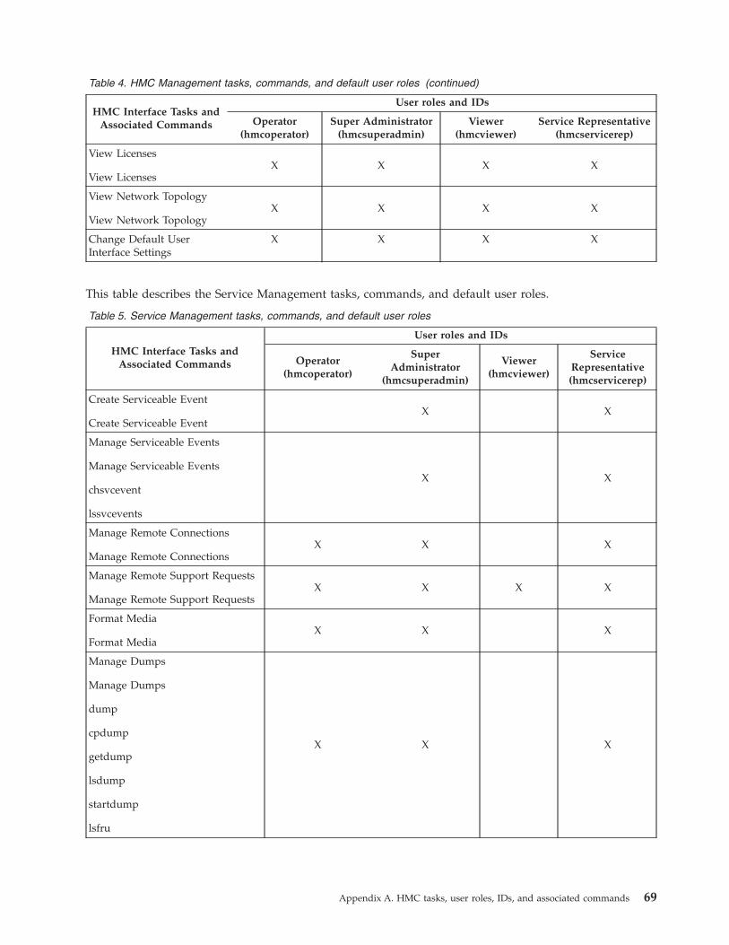
Table 4. HMC Management tasks, commands, and default user roles (continued)
HMC Interface Tasks andAssociated Commands
User roles and IDs
Operator(hmcoperator)
Super Administrator(hmcsuperadmin)
Viewer(hmcviewer)
Service Representative(hmcservicerep)
View Licenses
View LicensesX X X X
View Network Topology
View Network TopologyX X X X
Change Default UserInterface Settings
X X X X
This table describes the Service Management tasks, commands, and default user roles.
Table 5. Service Management tasks, commands, and default user roles
HMC Interface Tasks andAssociated Commands
User roles and IDs
Operator(hmcoperator)
SuperAdministrator
(hmcsuperadmin)
Viewer(hmcviewer)
ServiceRepresentative(hmcservicerep)
Create Serviceable Event
Create Serviceable EventX X
Manage Serviceable Events
Manage Serviceable Events
chsvcevent
lssvcevents
X X
Manage Remote Connections
Manage Remote ConnectionsX X X
Manage Remote Support Requests
Manage Remote Support RequestsX X X X
Format Media
Format MediaX X X
Manage Dumps
Manage Dumps
dump
cpdump
getdump
lsdump
startdump
lsfru
X X X
Appendix A. HMC tasks, user roles, IDs, and associated commands 69

Table 5. Service Management tasks, commands, and default user roles (continued)
HMC Interface Tasks andAssociated Commands
User roles and IDs
Operator(hmcoperator)
SuperAdministrator
(hmcsuperadmin)
Viewer(hmcviewer)
ServiceRepresentative(hmcservicerep)
Transmit Service Information
Transmit Service Information
chsacfg
lssacfg
X X
Enable Electronic Service Agent
Manage Systems Call-HomeX X X
Manage Outbound Connectivity
Manage Outbound ConnectivityX X X
Manage Inbound Connectivity
Manage Inbound ConnectivityX X X
Manage Customer Information
Manage Customer InformationX X X
Authorize User
Authorize UserX
Manage Serviceable EventNotification
Manage Serviceable EventNotification
chsacfg
lssacfg
X X X
Manage Connection Monitoring
Manage Connection MonitoringX X X X
Manage POWER4 Service Agent
Manage POWER4™ Service AgentX X
Electronic Service Agent SetupWizard
Call-Home Setup Wizard
X X
70 Operations Guide for the HMC and Managed Systems
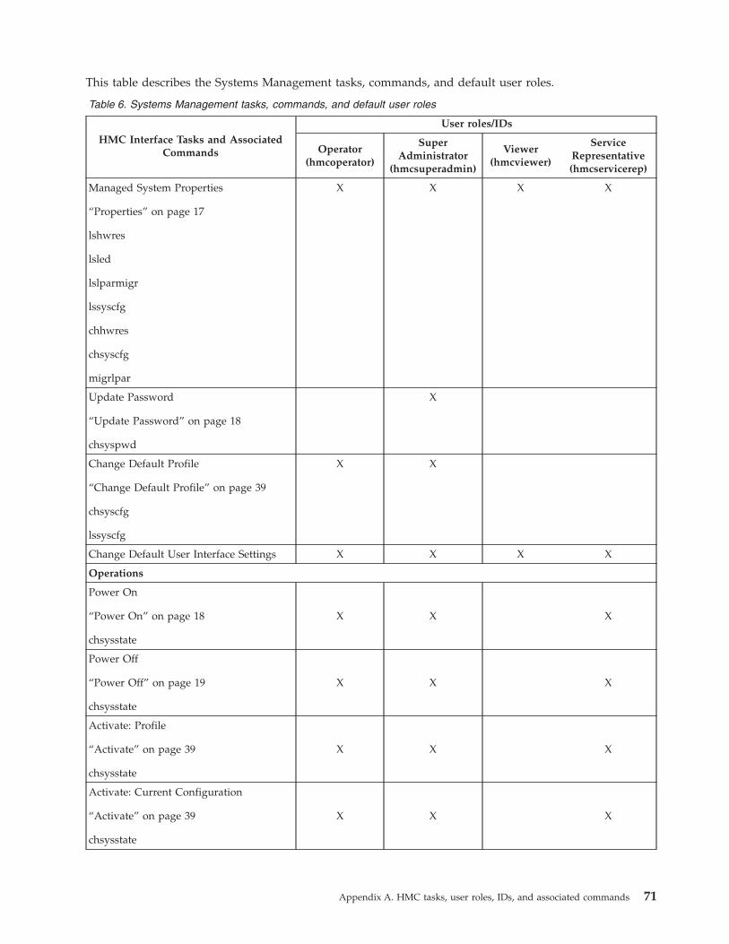
This table describes the Systems Management tasks, commands, and default user roles.
Table 6. Systems Management tasks, commands, and default user roles
HMC Interface Tasks and AssociatedCommands
User roles/IDs
Operator(hmcoperator)
SuperAdministrator
(hmcsuperadmin)
Viewer(hmcviewer)
ServiceRepresentative(hmcservicerep)
Managed System Properties
“Properties” on page 17
lshwres
lsled
lslparmigr
lssyscfg
chhwres
chsyscfg
migrlpar
X X X X
Update Password
“Update Password” on page 18
chsyspwd
X
Change Default Profile
“Change Default Profile” on page 39
chsyscfg
lssyscfg
X X
Change Default User Interface Settings X X X X
Operations
Power On
“Power On” on page 18
chsysstate
X X X
Power Off
“Power Off” on page 19
chsysstate
X X X
Activate: Profile
“Activate” on page 39
chsysstate
X X X
Activate: Current Configuration
“Activate” on page 39
chsysstate
X X X
Appendix A. HMC tasks, user roles, IDs, and associated commands 71

Table 6. Systems Management tasks, commands, and default user roles (continued)
HMC Interface Tasks and AssociatedCommands
User roles/IDs
Operator(hmcoperator)
SuperAdministrator
(hmcsuperadmin)
Viewer(hmcviewer)
ServiceRepresentative(hmcservicerep)
Restart
“Restart” on page 40
chsysstate
X X X
Shut Down
“Shut Down” on page 40
chsysstate
X X X
LED Status: Deactivate Attention LED
“Manage Attention LED” on page 41
chled
X X X X
LED Status: Identify LED
“Manage Attention LED” on page 41X X X X
LED Status: Test LED
“Manage Attention LED” on page 41X X X X
Schedule Operations
“Schedule Operations” on page 41X X
Launch Advanced System Management(ASM)
“Advanced System Management” onpage 22
asmmenu
X X X
Utilization Data: Change Sampling Rate
“Utilization Data” on page 22
chlparutil
lslparutil
X X X
Utilization Data: View
“Utilization Data” on page 22
lslparutil
X X X X
Rebuild
“Rebuild” on page 22
chsysstate
X X
Change Password
“Change Password” on page 23
chsyspwd
X
72 Operations Guide for the HMC and Managed Systems

Table 6. Systems Management tasks, commands, and default user roles (continued)
HMC Interface Tasks and AssociatedCommands
User roles/IDs
Operator(hmcoperator)
SuperAdministrator
(hmcsuperadmin)
Viewer(hmcviewer)
ServiceRepresentative(hmcservicerep)
Power Management
“Power Management” on page 19
chpwrmgmt
lspwrmgmt
X
Perform VIOS Command
“viosvrcmd” on page 42
viosvrcmd
X X X
Delete
“Delete” on page 43
rmsyscfg
X X X
Mobility: Migrate
“Migrate” on page 43
lslparmigr
migrlpar
X X X
Mobility: Validate
“Validate” on page 43
lslparmigr
migrlpar
X X X
Mobility: Recover
“Recover” on page 44
lslparmigr
migrlpar
X X X
Manage profiles
“Manage Profiles” on page 44
chsyscfg
lssyscfg
mksyscfg
rmsyscfg
chsysstate
X X X
Launch OS Management
“Operations” on page 39X X X X
Appendix A. HMC tasks, user roles, IDs, and associated commands 73
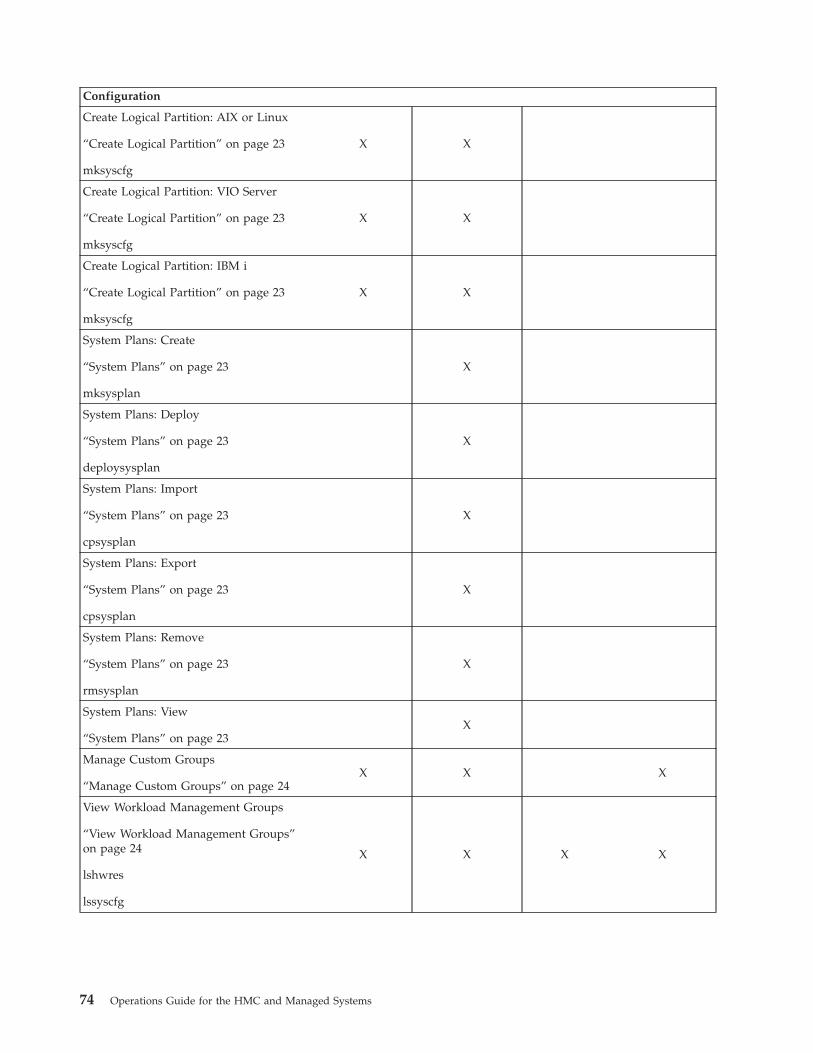
Configuration
Create Logical Partition: AIX or Linux
“Create Logical Partition” on page 23
mksyscfg
X X
Create Logical Partition: VIO Server
“Create Logical Partition” on page 23
mksyscfg
X X
Create Logical Partition: IBM i
“Create Logical Partition” on page 23
mksyscfg
X X
System Plans: Create
“System Plans” on page 23
mksysplan
X
System Plans: Deploy
“System Plans” on page 23
deploysysplan
X
System Plans: Import
“System Plans” on page 23
cpsysplan
X
System Plans: Export
“System Plans” on page 23
cpsysplan
X
System Plans: Remove
“System Plans” on page 23
rmsysplan
X
System Plans: View
“System Plans” on page 23X
Manage Custom Groups
“Manage Custom Groups” on page 24X X X
View Workload Management Groups
“View Workload Management Groups”on page 24
lshwres
lssyscfg
X X X X
74 Operations Guide for the HMC and Managed Systems

Partition Availability Priority
“Partition Availability Priority” on page23
chsyscfg
lssyscfg
mksyscfg
X X
Manage System Profiles
“Manage System Profiles” on page 25
chsyscfg
chsysstate
lssyscfg
mksyscfg
rmsyscfg
X X X X
Manage Partition Data: Restore
“Manage Partition Data” on page 24
rstprofdata
X X
Manage Partition Data: Initialize
“Manage Partition Data” on page 24
rstprofdata
X X
Manage Partition Data: Backup
“Manage Partition Data” on page 24
bkprofdata
X X X
Recover Partition Data
chsysstate
rstprofdata
X X X
Manage Partition Data: Delete
“Manage Partition Data” on page 24
rmprofdata
X X
Save Current Configuration
“Save Current Configuration” on page 44
mksyscfg
X X
Appendix A. HMC tasks, user roles, IDs, and associated commands 75

Virtual Resources: Shared Processor PoolManagement
“Shared processor pool management” onpage 26
chhwres
lshwres
X
Virtual Resources: Shared Memory PoolManagement
“Shared Memory Pool Management” onpage 26
lshwres
lsmemdev
chhwres
X
Virtual Resources: Virtual StorageManagement
“Virtual Storage Management” on page27
X
Virtual Resources: Virtual NetworkManagement
“Virtual Network Management” on page27
X
Connections
Service Processor Status
“Connections” on page 27
lssysconn
X X X X
Reset or Remove Connections
“Connections” on page 27
rmsysconn
X X
Disconnect Another HMC
“Connections” on page 27X
Add Managed System
“Connections” on page 27
mksysconn
X X
Hardware (Information)
76 Operations Guide for the HMC and Managed Systems

Adapters: Host Channel
“Host Channel Adapter (HCA)” on page31
lshwres
X X X X
Adapters: Host Ethernet
“Host Ethernet Adapter (HEA)” on page32
chhwres
lshwres
X X X X
Adapters: Switch Network Interface
“Switch Network Interface” on page 45
lshwres
X X X X
View Hardware Topology
“View Hardware Topology” on page 32X X X X
Virtual I/O Adapters: SCSI
“Virtual IO Adapters” on page 45
lshwres
X X X X
Virtual I/O Adapters: Ethernet
“Virtual IO Adapters” on page 45
lshwres
X X X X
Dynamic Logical Partitioning
Processor
“Processor” on page 46
chhwres
lshwres
X X X
Memory
“Memory” on page 46
chhwres
lshwres
X X X
Physical Adapters
“Physical Adapters” on page 46
chhwres
lshwres
X X X
Appendix A. HMC tasks, user roles, IDs, and associated commands 77

Virtual Adapter
“Virtual Adapter” on page 47
chhwres
lshwres
X X X
Host Ethernet
“Host Ethernet” on page 47
chhwres
lshwres
X X X
Updates
Change Licensed Internal Code for thecurrent release
“Change Licensed Internal Code for thecurrent release” on page 62
lslic
updlic
X X
Upgrade Licensed Internal Code to a newrelease
“Upgrade Licensed Internal Code to anew release” on page 63
lslic
updlic
X X
Check system readiness
“Check system readiness” on page 64
updlic
X X
View system information
“View system information” on page 64
lslic
X X
Update HMC
updhmc
lshmc
X X
Console Window
Open Terminal Window
Open Restricted Shell Terminal
mkvterm
X X X
Close Terminal Connection
rmvtermX X X
Open Shared 5250 Console X X X
78 Operations Guide for the HMC and Managed Systems

Open Dedicated 5250 Console X X X
Serviceability
Manage Serviceable Events
Manage Serviceable Events
chsvcevent
lssvcevents
X X
Create Serviceable Event
Create Serviceable EventX X
Reference Code History
“Reference Code History” on page 34
lsrefcode
X X X X
Control Panel Functions: (20) Type,Model, Feature
“Control Panel Functions” on page 34
lssyscfg
X X
Hardware: Add FRU
“Add FRU” on page 34X X
Hardware: Add Enclosure
“Add Enclosure” on page 34X X
Hardware: Exchange FRU
“Exchange FRU” on page 35X X
Hardware: Remove FRU
“Remove FRU” on page 35X X
Hardware: Remove Enclosure
“Remove Enclosure” on page 35X X
Hardware: Power On/Off Unit
“Power On/Off IO Unit” on page 35X X
Manage Dumps
“Manage Dumps” on page 36
dump
cpdump
getdump
lsdump
startdump
lsfru
X X X
Appendix A. HMC tasks, user roles, IDs, and associated commands 79
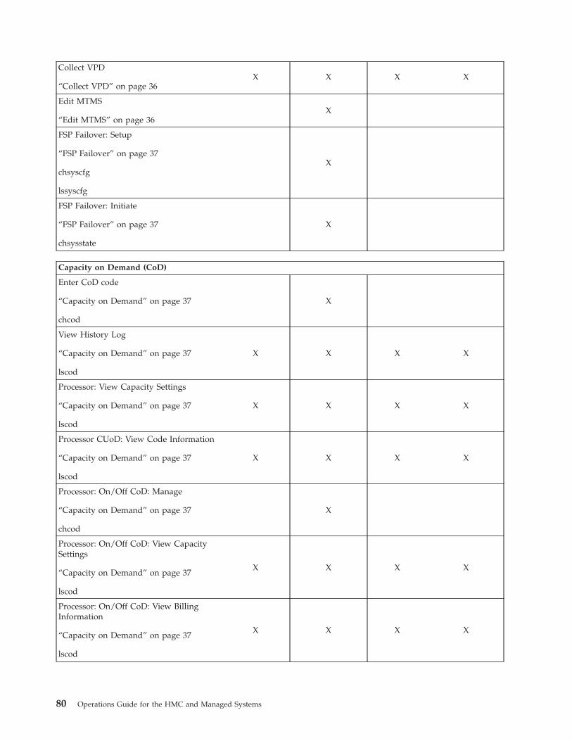
Collect VPD
“Collect VPD” on page 36X X X X
Edit MTMS
“Edit MTMS” on page 36X
FSP Failover: Setup
“FSP Failover” on page 37
chsyscfg
lssyscfg
X
FSP Failover: Initiate
“FSP Failover” on page 37
chsysstate
X
Capacity on Demand (CoD)
Enter CoD code
“Capacity on Demand” on page 37
chcod
X
View History Log
“Capacity on Demand” on page 37
lscod
X X X X
Processor: View Capacity Settings
“Capacity on Demand” on page 37
lscod
X X X X
Processor CUoD: View Code Information
“Capacity on Demand” on page 37
lscod
X X X X
Processor: On/Off CoD: Manage
“Capacity on Demand” on page 37
chcod
X
Processor: On/Off CoD: View CapacitySettings
“Capacity on Demand” on page 37
lscod
X X X X
Processor: On/Off CoD: View BillingInformation
“Capacity on Demand” on page 37
lscod
X X X X
80 Operations Guide for the HMC and Managed Systems

Processor: On/Off CoD: View CodeInformation
“Capacity on Demand” on page 37
lscod
X X X X
Processor: Trial CoD: Stop
“Capacity on Demand” on page 37
chcod
X
Processor: Trial CoD: View CapacitySettings
“Capacity on Demand” on page 37
lscod
X X X X
Processor: Trial CoD: View CodeInformation
“Capacity on Demand” on page 37
lscod
X X X X
Processor: Reserve CoD: Manage
“Capacity on Demand” on page 37
chcod
X
Processor: Reserve CoD: View CapacitySettings
“Capacity on Demand” on page 37
lscod
X X X X
Processor: Reserve CoD: View CodeInformation
“Capacity on Demand” on page 37
lscod
X X X X
Processor: Reserve CoD: View SharedProcessor Utilization
“Capacity on Demand” on page 37
lscod
X X X
PowerVM (formerly known as AdvancedPOWER Virtualization): Enter ActivationCode
“Capacity on Demand” on page 37
chcod
X
PowerVM: View History Log
“Capacity on Demand” on page 37
lscod
X X X X
Appendix A. HMC tasks, user roles, IDs, and associated commands 81

PowerVM: View Code Information
“Capacity on Demand” on page 37
lscod
X X X X
Enterprise Enablement: Enter ActivationCode
“Capacity on Demand” on page 37
chcod
X
Enterprise Enablement: View History Log
“Capacity on Demand” on page 37
lscod
X X X X
Enterprise Enablement: View CodeInformation
“Capacity on Demand” on page 37
lscod
X X X X
Other Advanced Functions: EnterActivation Code
“Capacity on Demand” on page 37
chcod
X
Other Advanced Functions: View HistoryLog
“Capacity on Demand” on page 37
lscod
X X X X
Other Advanced Functions: View CodeInformation
“Capacity on Demand” on page 37
lscod
X X X X
Processor: Manage
“Capacity on Demand” on page 37
chcod
X
Processor: View Capacity Settings
“Capacity on Demand” on page 37
lscod
X X X X
Processor: View Code Information
“Capacity on Demand” on page 37
lscod
X X X X
Memory: Manage
“Capacity on Demand” on page 37
chcod
X
82 Operations Guide for the HMC and Managed Systems

Memory: View Capacity Settings
“Capacity on Demand” on page 37
lscod
X X X X
Memory: View Code Information
“Capacity on Demand” on page 37
lscod
X X X X
This table describes the Frame Management tasks, commands, and default user roles.
Table 7. Frame management tasks, commands, and user roles
HMC Interface Tasksand Associated
Commands
User roles/IDs
Operator(hmcoperator)
Super Administrator(hmcsuperadmin)
Viewer (hmcviewer)Service
Representative(hmcservicerep)
Properties
“Properties” on page39
chsyscfg
lssyscfg
X X X X
Initialize Frame(s)
“Initialize Frames” onpage 52
X X X
Initialize All Frames
“Initialize AllFrames” on page 52
X X X
Power off unownedI/O drawers
chsysstate
X X X
Launch FrameAdvanced SystemManagement (ASM)
asmmenu
X X X X
Bulk Power Assembly(BPA) Status
“Bulk PowerAssembly (BPA)Status” on page 53
lssysconn
X X X X
Reset
“Reset” on page 54
rmsysconn
X X
Appendix A. HMC tasks, user roles, IDs, and associated commands 83

Table 7. Frame management tasks, commands, and user roles (continued)
HMC Interface Tasksand Associated
Commands
User roles/IDs
Operator(hmcoperator)
Super Administrator(hmcsuperadmin)
Viewer (hmcviewer)Service
Representative(hmcservicerep)
View VLAN NetworkData
X X X X
Serviceability
Hardware: Fill andDrain Tool Tasks: Filland Drain Tool Fill
X X
Hardware: Fill andDrain Tool Tasks: Filland Drain Tool Drain
X X
Hardware: Fill andDrain Tool Tasks: Filland Drain Tool FillNode
X X
Hardware: Fill andDrain Tool Tasks: Filland Drain Tool FillInitial System Fill
X X
Hardware: Fill andDrain Tool Tasks: Filland Drain Tool FillSystem Top Off
X X
This table describes the Control Panel Functions tasks, commands, and default user roles.
Table 8. Control Panel Functions tasks, commands, and user roles
HMC Interface Tasks andAssociated Commands
User roles/IDs
Operator(hmcoperator)
SuperAdministrator
(hmcsuperadmin)
Viewer(hmcviewer)
ServiceRepresentative(hmcservicerep)
Serviceability
(21) Activate Dedicated ServiceTools
“Control Panel Functions” on page49
chsysstate
X X
(65) Disable Remote Service
“Control Panel Functions” on page49
chsysstate
X X
(66) Enable Remote Service
“Control Panel Functions” on page49
chsysstate
X X
84 Operations Guide for the HMC and Managed Systems

Table 8. Control Panel Functions tasks, commands, and user roles (continued)
HMC Interface Tasks andAssociated Commands
User roles/IDs
Operator(hmcoperator)
SuperAdministrator
(hmcsuperadmin)
Viewer(hmcviewer)
ServiceRepresentative(hmcservicerep)
(67) DIsk Unit IOP Reset / Reload
“Control Panel Functions” on page49
chsysstate
X X
(68) Concurrent Maintenance PowerOff Domain
“Control Panel Functions” on page49
X X
(69) Concurrent Maintenance PowerOn Domain
“Control Panel Functions” on page49
X X
(70) IOP Control Storage Dump
“Control Panel Functions” on page49
chsysstate
X X
This table describes the commands that are not associated with an HMC UI task, and defines the defaultuser roles that can perform each command.
Table 9. Command line tasks, associated commands, and user roles
Command line tasks
User roles/IDs
Operator(hmcoperator)
SuperAdministrator
(hmcsuperadmin)
Viewer(hmcviewer)
ServiceRepresentative(hmcservicerep)
Change which encryption is usedby the HMC to encrypt thepasswords of locally authenticatedHMC users, or change whichencryptions can be used by theHMC Web UI.
chhmcencr
X
List which encryption is used bythe HMC to encrypt the passwordsof locally authenticated HMC users,or list which encryptions can beused by the HMC Web UI
chhmcfs
X X X
Free up space in HMC file systems
chhmcfsX X
Appendix A. HMC tasks, user roles, IDs, and associated commands 85
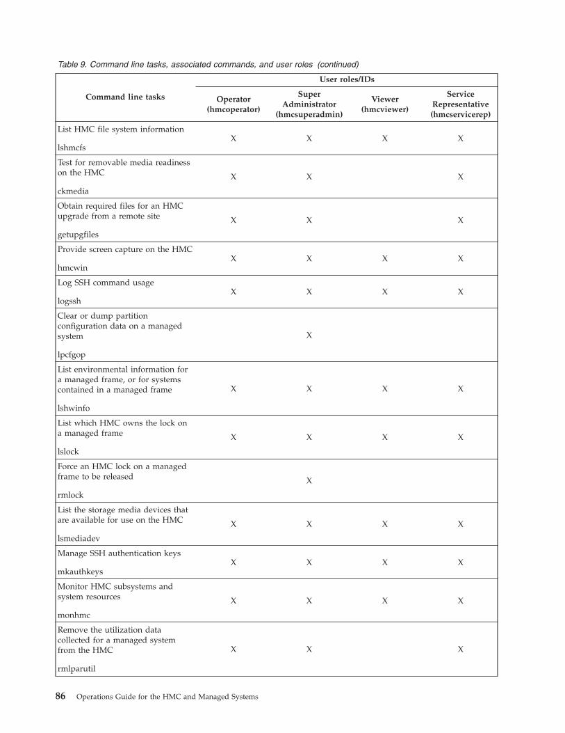
Table 9. Command line tasks, associated commands, and user roles (continued)
Command line tasks
User roles/IDs
Operator(hmcoperator)
SuperAdministrator
(hmcsuperadmin)
Viewer(hmcviewer)
ServiceRepresentative(hmcservicerep)
List HMC file system information
lshmcfsX X X X
Test for removable media readinesson the HMC
ckmedia
X X X
Obtain required files for an HMCupgrade from a remote site
getupgfiles
X X X
Provide screen capture on the HMC
hmcwinX X X X
Log SSH command usage
logsshX X X X
Clear or dump partitionconfiguration data on a managedsystem
lpcfgop
X
List environmental information fora managed frame, or for systemscontained in a managed frame
lshwinfo
X X X X
List which HMC owns the lock ona managed frame
lslock
X X X X
Force an HMC lock on a managedframe to be released
rmlock
X
List the storage media devices thatare available for use on the HMC
lsmediadev
X X X X
Manage SSH authentication keys
mkauthkeysX X X X
Monitor HMC subsystems andsystem resources
monhmc
X X X X
Remove the utilization datacollected for a managed systemfrom the HMC
rmlparutil
X X X
86 Operations Guide for the HMC and Managed Systems

Table 9. Command line tasks, associated commands, and user roles (continued)
Command line tasks
User roles/IDs
Operator(hmcoperator)
SuperAdministrator
(hmcsuperadmin)
Viewer(hmcviewer)
ServiceRepresentative(hmcservicerep)
Enable users to edit a text file onthe HMC in a restricted mode
rnvi
X X X X
Restore hardware resources after aDLPAR failure
rsthwres
X
Restore upgrade data on the HMC
rstupgdataX X X
Transfer a file from the HMC to aremote system
sendfile
X X X X
Appendix A. HMC tasks, user roles, IDs, and associated commands 87

88 Operations Guide for the HMC and Managed Systems

Appendix B. Remote operations
Connect to and use the HMC remotely.
Remote operations use the GUI used by a local HMC operator or the command line interface (CLI) on theHMC. You can perform operations remotely in the following ways:v Use a remote HMCv Use a Web browser to connect to a local HMCv Use an HMC remote command line
The remote HMC is an HMC that is on a different subnet from the service processor, therefore the serviceprocessor cannot be auto discovered with IP multicast.
To determine whether to use a remote HMC or Web browser connected to a local HMC, consider thescope of control that you need. A remote HMC defines a specific set of managed objects that are directlycontrolled by the remote HMC, while a Web browser to a local HMC has control over the same set ofmanaged objects as the local HMC. The communications connectivity and communications speed is anadditional consideration; LAN connectivity provides acceptable communications for either a remote HMCor Web browser control.
Using a remote HMCA remote HMC gives the most complete set of functions because it is a complete HMC; only the processof configuring the managed objects is different from a local HMC.
As a complete HMC, a remote HMC has the same setup and maintenance requirements as a localHardware Management Console. A remote HMC needs LAN TCP/IP connectivity to each managedobject (service processor) that is to be managed; therefore, any customer firewall that may exist betweenthe remote HMC and its managed objects must permit HMC to service processor communications tooccur. A remote HMC may also need communication with another HMC for service and support. Table 10shows the ports a remote HMC uses for communications.
Table 10. Ports used by a Remote HMC for Communications
Port Use
udp 9900 HMC to HMC discovery
tcp 9920 HMC to HMC commands
A remote HMC needs connectivity to IBM (or another HMC that has connectivity to IBM) for service andsupport. The connectivity to IBM may be in the form of access to the internet (through a companyfirewall), or a dialed connection through a customer-provided switched phone connection using thesupplied modem (see Manage Outbound Connectivity). A remote HMC cannot use the supplied modemfor communication with a local HMC or a service processor.
Performance and the availability of the status information and access to the control functions of theservice processor depends on the reliability, availability, and responsiveness of the customer network thatinterconnects the remote HMC with the managed object. A remote HMC monitors the connection to eachservice processor and attempts to recover any lost connections and can report those connections thatcannot be recovered.
© Copyright IBM Corp. 2007, 2008 89

Security for a remote HMC is provided by the HMC user-login procedures in the same way as a localHMC. As with a local HMC, all communication between a remote HMC and each service processor isencrypted. Certificates for secure communications are provided, and can be changed by the user ifdesired (see Manage Certificates).
TCP/IP access to the remote HMC is controlled through its internally managed firewall and is limited toHMC related functions.
Using a Web browserIf you need occasional monitoring and control of managed objects connected to a single local HMC, use aWeb browser. An example of using the Web browser might be an off-hours monitor from home by anoperator or system programmer.
Each HMC contains a Web server that can be configured to allow remote access for a specified set ofusers. If a customer firewall exists between the Web browser and the local HMC, the ports must beaccessible, and the firewall should allow incoming requests on these ports. Table 11 shows the ports aWeb browser needs for communicating with an HMC.
Table 11. Ports used by a Web browser for communications to the HMC
Port Use
tcp 443 Secure browser access to Web server communication
tcp 8443 Secure browser access to Web server communication
tcp 9960 Browser applet communication
After an HMC has been configured to allow Web browser access, a Web browser gives an enabled useraccess to all the configured functions of a local HMC, except those functions that require physical accessto the HMC, such as those that use the local diskette or DVD media. The user interface presented to theremote Web browser user is the same as that of the local HMC and is subject to the same constraints asthe local HMC.
The Web browser can be connected to the local HMC using a LAN TCP/IP connection and using onlyencrypted (HTTPS) protocols. Logon security for a Web browser is provided by the HMC user-loginprocedures. Certificates for secure communications are provided, and can be changed by the user (seeManage Certificates).
Performance and the availability of the status information and access to the control functions of themanaged objects depends on the reliability, availability, and responsiveness of the network thatinterconnects the Web browser with the local HMC. Because there is no direct connection between theWeb browser and the individual managed objects, the Web browser does not monitor the connection toeach service processor, does not do any recovery, and does not report any lost connections. Thesefunctions are handled by the local HMC
The Web browser system does not require connectivity to IBM for service or support. Maintenance of thebrowser and system level is the responsibility of the customer.
If the URL of the HMC is specified using the format https://xxx.xxx.xxx.xxx (where xxx.xxx.xxx.xxx is theIP address) and Microsoft® Internet Explorer is used as the browser, a hostname mismatch message isdisplayed. To avoid this message, a Firefox browser is used or a hostname is configured for the HMC,using the Change Network Settings task (see Change Network Settings), and this hostname is specifiedin the URL instead of an IP address. For example, you can use the format https://hostname.domain_nameor https://hostname (for example, using https://hmc1.ibm.com or https://hmc1).
90 Operations Guide for the HMC and Managed Systems
Using the HMC remote command lineAn alternative to performing tasks on the HMC graphical user interface is using the command lineinterface (CLI).
You can use the command line interface in the following situations:v When consistent results are required. If you have to administer several managed systems, you can
achieve consistent results by using the command line interface. The command sequence can be storedin scripts and run remotely.
v When automated operations are required. After you have developed a consistent way to manage themanaged systems, you can automate the operations by invoking the scripts from batch-processingapplications, such as the cron daemon, from other systems.
On a local HMC, you can use the command line interface in a terminal window. To open a terminalwindow, use the Open Restricted Shell Terminal task from the HMC Management work pane.
Setting up secure script execution between SSH clients and the HMCYou must ensure that your script executions between SSH clients and the HMC are secure.
HMCs typically are placed inside the machine room where managed systems are located, so you mightnot have physical access to the HMC. In this case, you can remotely access it using either a remote Webbrowser or the remote command line interface.
Note: To enable scripts to run unattended between an SSH client and an HMC, the SSH protocol mustalready be installed on the client’s operating system.
To enable scripts to run unattended between an SSH client and an HMC, do the following:1. Enable remote command execution. For more information, see “Enabling and disabling HMC remote
commands” on page 922. On the client’s operating system, run the SSH protocol key generator. To run the SSH protocol key
generator, do the following:a. To store the keys, create a directory named $HOME/.ssh (either RSA or DSA keys can be used).b. To generate public and private keys, run the following command:
ssh-keygen -t rsa
The following files are created in the $HOME/.ssh directory:private key: id_rsapublic key: id_rsa.pub
The write bits for both group and other are turned off. Ensure that the private key has apermission of 600.
3. On the client’s operating system, use ssh and run the mkauthkeys command to update the HMCuser’s authorized_keys2 file on the HMC by using the following command:ssh hmcuser@hmchostname “mkauthkeys -–add ’<the contents of $HOME/ .ssh/id_rsa.pub>’ “ “
To delete the key from the HMC, can use the following command:
ssh hmcuser@hmchostname “mkauthkeys --remove ’joe@somehost’ “
To enable password prompting for all hosts that access the HMC through ssh, use the scp command tocopy the key file from the HMC: scp hmcuser@hmchostname:.ssh/authorized_keys2 authorized_keys2
Edit the authorized_keys2 file and remove all lines in this file. Then copy it back to the HMC: scpauthorized_keys2 hmcuser@hmchostname:.ssh/authorized_keys2
Appendix B. Remote operations 91

Enabling and disabling HMC remote commandsYou can enable or disable the remote command line interface access to the HMC.
To enable or disable remote commands, do the following:1. Open the Remote Command Execution task from the HMC Management work pane.2. From the Remote Command Execution window:
v To enable remote commands, select Enable remote command execution using the ssh facility.v To disable remote commands, make sure Enable remote command execution using the ssh facility
is not selected.3. Click OK.
Web browser requirementsLearn about the requirements your Web browser must meet to monitor and control the HMC.
HMC Web browser support requires HTML 2.0, JavaScript 1.0, Java™ Virtual Machine (JVM), and cookiesupport in browsers that will connect to the HMC. Contact your support personnel to assist you indetermining if your browser is configured with a Java Virtual Machine. The Web browser must use theHTTP 1.1 protocol; and if you are using a proxy server, the HTTP 1.1 protocol must be enabled for theproxy connections. Additionally, pop-ups must be enabled for all HMCs addressed in the browser ifrunning with pop-ups disabled. The following browsers have been tested:
Microsoft Internet Explorer 6.0 or laterIf the Microsoft Internet Explorer browser is configured to use an internet proxy, then includelocal intranet addresses in the exception list. Consult your network administrator for moreinformation. If you still need to use the proxy, access the HMC then enable Use HTTP 1.1through proxy connections under the Advanced tab in your Internet Options window.
Firefox 1.5.0.6 or laterFor Firefox 2.0, make sure to enable the JavaScript™ option to raise or lower windows and moveor resize existing windows is enabled.
Preparing to use the Web browserPerform the necessary steps to prepare to use a Web browser to access the HMC.
Before you can use a Web browser to access an HMC, you must do the following:v Configure the HMC to allow remote control for specified users.v For LAN-based connections, know the TCP/IP address of the HMC to be controlled, and have
correctly set up any firewall access between the HMC and the Web browser.v Have a valid user ID and password assigned by the access administrator for HMC Web access.
Logging in to the HMC from a LAN-connected Web browserLog in to the HMC remotely from a LAN-connected Web browser.
Use the following steps to log in to the HMC from a LAN-connected Web browser:1. Ensure that your Web browser PC has LAN connectivity to the desired HMC.2. From your Web browser, enter the URL of the desired HMC, using the format https://
hostname.domain_name (for example: https://hmc1.ibm.com) or https://xxx.xxx.xxx.xxx.If this is the first access of the HMC for the current Web browser session, you can receive a certificateerror. This certificate error is displayed if:v The Web server contained in the HMC is configured to use a self-signed certificate and the browser
has not been configured to trust the HMC as an issuer of certificates,
92 Operations Guide for the HMC and Managed Systems

v The HMC is configured to use a certificate signed by a Certificate Authority (CA) and the browserhas not been configured to trust this CA.
In either case, if you know that the certificate being displayed to the browser is the one used by theHMC, you can continue and all communications to the HMC will be encrypted.If you do not want to receive notification of a certificate error for the first access of any browsersession, you can configure the browser to trust the HMC or the CA. In general, to configure thebrowser, use one of the following methods:v You must indicate that the browser will permanently trust the issuer of the certificatev By viewing the certificate and installing, to the database of trusted CAs, the certificate of the CA
that issued the certificate used by the HMC.If the certificate is self-signed, the HMC itself is considered the CA that issued the certificate.
3. When prompted, enter the user name and password assigned by your administrator.
Appendix B. Remote operations 93

94 Operations Guide for the HMC and Managed Systems

Appendix C. Customizable data replication
The Customizable Data Replication service provides the ability to configure a set of HardwareManagement Consoles (HMCs) to automatically replicate any changes to certain types of data so that theconfigured set of HMCs automatically keep this data synchronized without manual intervention.
Note: Before enabling this replication service, you may want to save your original data settings in caseyou need to restore these settings at a future time. See Save Upgrade Data.
The following types of data can be configured:v Customer information data
– Administrator information (customer name, address, telephone number, and so on.)– System information (administrator name, address, telephone of your system)– Account information (customer number, enterprise number, sales branch office, and so on.)
v Group data– All user-defined group definitions
v Modem configuration data– Configure modem for remote support
v Outbound connectivity data– Configure local modem to RSF– Enable an internet connection– Configure to an external time source
The Customizable Data Replication service can be enabled for the following types of operations:v Peer-to-Peer (see “Peer-to-Peer replication”).
Provides automatic replication of the selected customized data types between peer HMCs. Changesmade on any of these consoles are replicated to the other consoles.
v Master-to-Slave (see “Master-to-Slave replication” on page 96).Provides automatic replication of the selected customized data types from one or more designatedmaster HMCs to one or more designated slave HMCs. Changes made on a master console areautomatically replicated to the slave console.
Peer-to-Peer replicationConfigure automatic replication of the selected customized data types between peer HMCs.
To configure automatic replication of the selected customized data types between peer HMCs, do thefollowing:1. Log in the HMC using a user ID that has administrator roles.2. In the HMC Management work pane, click Manage Data Replication.3. Select Enable.4. Click New.5. Select an HMC to be used as a data source from the list, and click Add.
orIn the TCP/IP Address Information field, type the TCP/IP address of the Hardware ManagementConsole to be a used as a data source, and then click Find.
6. In the Customizable Data Types list, select the types of data that you want to replicate from a peerHMC currently selected.
© Copyright IBM Corp. 2007, 2008 95

7. Choose one of the following actions:v Click Save to close the Manage Data Replication window.v Click Push to Slaves to transfer all local levels to any communicating slave. The slaves, if they are
running this level of code, are instructed to accept the levels from the master, regardless of thevalue of their current levels.
v Click Sync from Master to invalidate the local levels for all properties that are defined to have amaster. This results in an immediate level set where the master provide their levels to the localmachine. This option is not available if the local HMC is not defined to have any data sources.
v Click Status to show the status of this task on this machine.8. Repeat these steps on each of the HMCs that you want to act as peers with one another. Once
communication is established between the HMCs, the requested types of customizable data areautomatically replicated from one HMC to the other immediately following the change in the dataitself.
Master-to-Slave replicationMaster-to-Slave replication provides automatic replication of the selected customized data types from oneor more designated master HMCs to one or more designated slave HMCs.
To set up a master console, do the following:1. Log in the HMC using a user ID that has administrator roles.2. From the HMC Management work pane, click Manage Data Replication.3. Select Enable, then click Save.
Note: If you want to configure additional master consoles, see “Peer-to-Peer replication” on page 95
To set up the slave console, do the following:1. Log in the HMC using a user ID that has administrator roles.2. Select Manage Data Replication.3. Select Enable.4. Click New.5. Select an HMC to be used as a master data source from the list, then click Add.
orIn the TCP/IP Address Information field, enter the TCP/IP address of the HMC to be used as themaster data source, then click Find.
6. Select the types of data that you want to accept from the HMC.
Note: When configuring a HMC as a slave, you should check the types of customizable data from theLocal Customizable Data Change Warnings list that should generate warnings to a user whenmanual changes are made to that data on this HMC. Manually updating data on the slave HMC willchange the local data level to a higher level than the master. Changes on the master HMC will thennot replicate to this HMC until the master data level exceeds that on the slave, or a Sync from Masteror Push to Slaves task is run to resynchronize the data levels on master and slave.
7. Choose one of the following actions:v Click Save to close the Manage Data Replication window.v Click Push to Slaves to transfer all local levels to any communicating slave. The slaves, if they are
running this level of code, are instructed to accept the levels from the master, regardless of thevalue of their current levels.
96 Operations Guide for the HMC and Managed Systems

v Click Sync from Master to invalidate the local levels for all properties that are defined to have amaster. This results in an immediate level set where the masters provide their levels to the localmachine. This option is not available if the local Hardware Management Console is not defined tohave any data sources.
v Click Status to show the status of this task on this machine.8. Repeat these steps on any additional HMCs that you want to configure as a slave.9. Once communication is established between all of the HMCs, the master consoles remains
synchronized with each other, providing redundancy in the event that one of the master consolesbecomes unavailable. The slave consoles are kept synchronized with whichever master consoleprovides the data to them first.
Data replicationAs data is replicated from one HMC to another, an internal level indicator for the data being replicated isrecorded each time the data is altered on the data source. Learn about how to force the replication of datafrom one or more data sources.
Each HMC keeps track of the level indicator for each type of data and will not accept data from a datasource when the level indicator is not greater than that on the receiving HMC.
If you need to force the replication of data from one or more data sources and the level indicator on thereceiving HMC is greater than that of the data sources, do the following:1. Log in the HMC using a user ID that has administrator roles.2. In the HMC Management work pane, click Manage Data Replication.3. Deselect all the data types from the Customizable Data Types list.
Note: If you just want to reset the level indicator for a particular data type, just deselect that datatype.
4. Click Save.5. In the HMC Management work pane, click Manage Data Replication.6. Select the types of data from the Customizable Data Types list you just deselected.7. Click Save.
Note: Deselecting and then reselecting the data types resets the internal level indicators for the specifiedtypes of data and forces replication of the data from the data sources.
Appendix C. Customizable data replication 97

98 Operations Guide for the HMC and Managed Systems
Appendix D. HMC commands
HMC command information, including examples, is available from the HMC command line using theman command. For more information, you can also refer to the following Web addresshttps://www14.software.ibm.com/webapp/set2/sas/f/hmc/home.html) and“Using the HMC remotecommand line” on page 91.
To view the command information, type man and then the command name. For example, to learn moreabout the ″Create a user for the HMC″ (mkhmcusr) command, type the following at the command line:
man mkhmcusr
© Copyright IBM Corp. 2007, 2008 99

100 Operations Guide for the HMC and Managed Systems

Notices
This information was developed for products and services offered in the U.S.A.
The manufacturer may not offer the products, services, or features discussed in this document in othercountries. Consult the manufacturer’s representative for information on the products and servicescurrently available in your area. Any reference to the manufacturer’s product, program, or service is notintended to state or imply that only that product, program, or service may be used. Any functionallyequivalent product, program, or service that does not infringe any intellectual property right of themanufacturer may be used instead. However, it is the user’s responsibility to evaluate and verify theoperation of any product, program, or service.
The manufacturer may have patents or pending patent applications covering subject matter described inthis document. The furnishing of this document does not give you any license to these patents. You cansend license inquiries, in writing, to the manufacturer.
The following paragraph does not apply to the United Kingdom or any other country where suchprovisions are inconsistent with local law: THIS INFORMATION IS PROVIDED “AS IS” WITHOUTWARRANTY OF ANY KIND, EITHER EXPRESS OR IMPLIED, INCLUDING, BUT NOT LIMITED TO,THE IMPLIED WARRANTIES OF NON-INFRINGEMENT, MERCHANTABILITY OR FITNESS FOR APARTICULAR PURPOSE. Some states do not allow disclaimer of express or implied warranties in certaintransactions, therefore, this statement may not apply to you.
This information could include technical inaccuracies or typographical errors. Changes are periodicallymade to the information herein; these changes will be incorporated in new editions of the publication.The manufacturer may make improvements and/or changes in the product(s) and/or the program(s)described in this publication at any time without notice.
Any references in this information to Web sites not owned by the manufacturer are provided forconvenience only and do not in any manner serve as an endorsement of those Web sites. The materials atthose Web sites are not part of the materials for this product and use of those Web sites is at your ownrisk.
The manufacturer may use or distribute any of the information you supply in any way it believesappropriate without incurring any obligation to you.
Any performance data contained herein was determined in a controlled environment. Therefore, theresults obtained in other operating environments may vary significantly. Some measurements may havebeen made on development-level systems and there is no guarantee that these measurements will be thesame on generally available systems. Furthermore, some measurements may have been estimated throughextrapolation. Actual results may vary. Users of this document should verify the applicable data for theirspecific environment.
Information concerning products not produced by this manufacturer was obtained from the suppliers ofthose products, their published announcements or other publicly available sources. This manufacturer hasnot tested those products and cannot confirm the accuracy of performance, compatibility or any otherclaims related to products not produced by this manufacturer. Questions on the capabilities of productsnot produced by this manufacturer should be addressed to the suppliers of those products.
All statements regarding the manufacturer’s future direction or intent are subject to change or withdrawalwithout notice, and represent goals and objectives only.
© Copyright IBM Corp. 2007, 2008 101

The manufacturer’s prices shown are the manufacturer’s suggested retail prices, are current and aresubject to change without notice. Dealer prices may vary.
This information is for planning purposes only. The information herein is subject to change before theproducts described become available.
This information contains examples of data and reports used in daily business operations. To illustratethem as completely as possible, the examples include the names of individuals, companies, brands, andproducts. All of these names are fictitious and any similarity to the names and addresses used by anactual business enterprise is entirely coincidental.
If you are viewing this information in softcopy, the photographs and color illustrations may not appear.
The drawings and specifications contained herein shall not be reproduced in whole or in part without thewritten permission of the manufacturer.
The manufacturer has prepared this information for use with the specific machines indicated. Themanufacturer makes no representations that it is suitable for any other purpose.
The manufacturer’s computer systems contain mechanisms designed to reduce the possibility ofundetected data corruption or loss. This risk, however, cannot be eliminated. Users who experienceunplanned outages, system failures, power fluctuations or outages, or component failures must verify theaccuracy of operations performed and data saved or transmitted by the system at or near the time of theoutage or failure. In addition, users must establish procedures to ensure that there is independent dataverification before relying on such data in sensitive or critical operations. Users should periodically checkthe manufacturer’s support websites for updated information and fixes applicable to the system andrelated software.
TrademarksIBM, the IBM logo, and ibm.com are trademarks or registered trademarks of International BusinessMachines Corp., registered in many jurisdictions worldwide. Other product and service names might betrademarks of IBM or other companies. A current list of IBM trademarks is available on the Web atCopyright and trademark information at www.ibm.com/legal/copytrade.shtml.
INFINIBAND, InfiniBand Trade Association, and the INFINIBAND design marks are trademarks and/orservice marks of the INFINIBAND Trade Association.
Linux is a registered trademark of Linus Torvalds in the United States, other countries, or both.
Microsoft, Windows, Windows NT, and the Windows logo are trademarks of Microsoft Corporation in theUnited States, other countries, or both.
Red Hat, the Red Hat ″Shadow Man″ logo, and all Red Hat-based trademarks and logos are trademarksor registered trademarks of Red Hat, Inc., in the United States and other countries.
Java and all Java-based trademarks and logos are trademarks of Sun Microsystems, Inc. in the UnitedStates, other countries, or both.
Other company, product, or service names may be trademarks or service marks of others.
Terms and conditionsPermissions for the use of these publications is granted subject to the following terms and conditions.
102 Operations Guide for the HMC and Managed Systems

Personal Use: You may reproduce these publications for your personal, noncommercial use provided thatall proprietary notices are preserved. You may not distribute, display or make derivative works of thesepublications, or any portion thereof, without the express consent of the manufacturer.
Commercial Use: You may reproduce, distribute and display these publications solely within yourenterprise provided that all proprietary notices are preserved. You may not make derivative works ofthese publications, or reproduce, distribute or display these publications or any portion thereof outsideyour enterprise, without the express consent of the manufacturer.
Except as expressly granted in this permission, no other permissions, licenses or rights are granted, eitherexpress or implied, to the publications or any information, data, software or other intellectual propertycontained therein.
The manufacturer reserves the right to withdraw the permissions granted herein whenever, in itsdiscretion, the use of the publications is detrimental to its interest or, as determined by the manufacturer,the above instructions are not being properly followed.
You may not download, export or re-export this information except in full compliance with all applicablelaws and regulations, including all United States export laws and regulations.
THE MANUFACTURER MAKES NO GUARANTEE ABOUT THE CONTENT OF THESEPUBLICATIONS. THESE PUBLICATIONS ARE PROVIDED ″AS-IS″ AND WITHOUT WARRANTY OFANY KIND, EITHER EXPRESSED OR IMPLIED, INCLUDING BUT NOT LIMITED TO IMPLIEDWARRANTIES OF MERCHANTABILITY, NON-INFRINGEMENT, AND FITNESS FOR A PARTICULARPURPOSE.
Notices 103

104 Operations Guide for the HMC and Managed Systems