Operations and Maintenance Plan (Final) - Skanska Conformed... · Operations and Maintenance Plan...
60
Operations and Maintenance Plan (Final) Task No. 7.16.36 (Deliverable No. 7.16.36) Prepared for: Prepared by: The Connector Partnership 777 S. Figueroa Street Tenth Floor Los Angeles, California 90017 Review Copy Date Initials Originator 8/15/2013 CJ/PS Checker 8/21/2013 LM/WHH Back checker (for Final) 9/10/2013 WHH Approved by 9/10/2013 DS September 10, 2013 REGIONAL CONNECTOR TRANSIT CORRIDOR PROJECT Contract No. E0119
Transcript of Operations and Maintenance Plan (Final) - Skanska Conformed... · Operations and Maintenance Plan...

`
Operations and Maintenance Plan (Final) Task No. 7.16.36 (Deliverable No. 7.16.36) Prepared for:
Prepared by: The Connector Partnership 777 S. Figueroa Street Tenth Floor Los Angeles, California 90017
Review Copy Date Initials Originator 8/15/2013 CJ/PS Checker 8/21/2013 LM/WHH Back checker (for Final)
9/10/2013 WHH
Approved by 9/10/2013 DS September 10, 2013
REGIONAL CONNECTOR TRANSIT CORRIDOR PROJECT Contract No. E0119

Operations and Maintenance Plan (Final)
Table of Contents
R E G I O N A L C O N N E C T O R T R A N S I T C O R R I D O R P R O J E C T Page i September 10, 2013
Table of Contents 1.0 INTRODUCTION ......................................................................................................... 1-1
1.1 Purpose of the Operating and Maintenance Plan ........................................ 1-1
1.2 Metro Regional Connector Line Service Objectives .................................... 1-1
2.0 SYSTEM DESCRIPTION AND CHARACTERISTICS ................................................. 2-1
2.1 Metro Light Rail Overview ............................................................................. 2-1
2.2 Metro Regional Connector Line Project Description ................................... 2-1 2.2.1 Hours of Operation ............................................................................... 2-2
2.3 Metro Regional Connector Light Rail Facilities and Systems .................... 2-3 2.3.1 Stations and System Accessibility ........................................................ 2-3 2.3.2 Revenue Vehicle Fleet ......................................................................... 2-3 2.3.3 Vehicle Fleet Maintenance and Train Storage Facility .......................... 2-4 2.3.4 Mainline Track Segments ..................................................................... 2-4 2.3.5 Special Track Work .............................................................................. 2-5 2.3.6 Connections to Other Rail Systems ...................................................... 2-5 2.3.7 Emergency Ventilation Systems ........................................................... 2-5 2.3.8 Ancillary Space HVAC Systems ........................................................... 2-7 2.3.9 Traction Power Systems ....................................................................... 2-7 2.3.10 Emergency Generators ........................................................................ 2-7 2.3.11 Rail Operations Center ......................................................................... 2-7 2.3.12 Train Control System ............................................................................ 2-8 2.3.13 Communications System ...................................................................... 2-8 2.3.14 Fare Collection System ........................................................................ 2-9 2.3.15 Safety and Security Program ................................................................ 2-9 2.3.16 Connections with the Metro Bus Network ............................................. 2-9
3.0 OPERATIONS ............................................................................................................. 3-1
3.1 Introduction .................................................................................................... 3-1
3.2 Train Services ................................................................................................ 3-1 3.2.1 Weekday Early Morning Service Frequency ......................................... 3-2 3.2.2 Weekday Peak Period Service Frequency ............................................ 3-2 3.2.3 Weekday Mid-Day Service Frequency .................................................. 3-2 3.2.4 Weekday Evening Service Frequency .................................................. 3-3 3.2.5 Weekday Late Night Service Frequency ............................................... 3-3 3.2.6 Weekend/Holiday Service Frequency ................................................... 3-3
3.3 Travel Times ................................................................................................... 3-3 3.3.1 Travel Times between Stations ............................................................ 3-3 3.3.2 Accommodating the Elderly and Disabled ............................................ 3-7 3.3.3 Estimated Run Times ........................................................................... 3-7 3.3.4 Train Operations ................................................................................... 3-8
3.4 Regional Connector Operations ................................................................... 3-8 3.4.1 Pre-Revenue Operations – Regional Connector ................................... 3-8 3.4.2 Train Operations ................................................................................... 3-9 3.4.3 Duty Assignments ................................................................................ 3-9

Operations and Maintenance Plan (Final)
Table of Contents
R E G I O N A L C O N N E C T O R T R A N S I T C O R R I D O R P R O J E C T Page ii September 10, 2013
3.5 Train Consists ................................................................................................ 3-9
3.6 Terminal Dwell Times .................................................................................... 3-9
3.7 Station Dwell Times & Other Simulation Parameters ................................ 3-10
4.0 WAYSIDE SYSTEMS MAINTENANCE ....................................................................... 4-1
4.1 Management and Supervision ...................................................................... 4-1
4.2 Track ............................................................................................................... 4-3
4.3 Rail Communications .................................................................................... 4-5
4.4 Signals ............................................................................................................ 4-7
4.5 Traction Power ............................................................................................... 4-9
4.6 Facilities Maintenance and Custodial Systems ......................................... 4-11
4.7 SCADA Systems Engineering and Maintenance ....................................... 4-12
4.8 Transit Systems Engineering ...................................................................... 4-13
4.9 Maintenance of Way Systems Engineering ................................................ 4-14
5.0 RAIL FLEET AND RAIL FLEET SERVICES ............................................................... 5-1
5.1 Description of Metro Light Rail System Fleet .............................................. 5-1 5.1.1 Fleet Interchangeability ........................................................................ 5-1 5.1.2 Rail Fleet Management Plan ................................................................ 5-1
5.2 Rail Fleet Inspection and Maintenance......................................................... 5-1 5.2.1 Maintenance Yards .............................................................................. 5-1 5.2.2 Daily Inspection, Cleaning and Servicing .............................................. 5-2 5.2.3 Unscheduled Maintenance and Repair ................................................. 5-2 5.2.4 Overhaul/Rebuild Program ................................................................... 5-2 5.2.5 Emergency Response Capabilities ....................................................... 5-2
6.0 RULES, SAFETY, SECURITY AND TRAINING .......................................................... 6-1
6.1 Responsibility for Safety and Security ......................................................... 6-1
6.2 System Safety Program Plan ........................................................................ 6-2
6.3 Regulatory Agencies ..................................................................................... 6-2 6.3.1 Federal Transit Administration .............................................................. 6-2 6.3.2 Federal Communication Commission ................................................... 6-2 6.3.3 Occupational Safety and Health Administration (OSHA) ....................... 6-2 6.3.4 California Public Utilities Commission (CPUC) ..................................... 6-2
6.4 Industry Organizations and Standards......................................................... 6-3 6.4.1 American Public Transportation Association (APTA) ............................ 6-3 6.4.2 American Railway Engineering and Maintenance-of-Way Association
(AREMA) .............................................................................................. 6-3 6.4.3 National Fire Protection Association (NFPA) ........................................ 6-3
6.5 Operating Rules ............................................................................................. 6-3
6.6 Standard Operating Procedures ................................................................... 6-3

Operations and Maintenance Plan (Final)
Table of Contents
R E G I O N A L C O N N E C T O R T R A N S I T C O R R I D O R P R O J E C T Page iii September 10, 2013
6.7 Work Instructions .......................................................................................... 6-4
6.8 Training and Qualification ............................................................................. 6-4
7.0 SERVICE INTERRUPTIONS AND EMERGENCIES ................................................... 7-0
7.1 Principal Objectives ....................................................................................... 7-0 7.1.1 Safety and Security .............................................................................. 7-0 7.1.2 Loss and Damage Mitigation ................................................................ 7-0 7.1.3 System Recovery ................................................................................. 7-0
7.2 Service Recovery Scenarios ......................................................................... 7-0 7.2.1 Vehicle Incidents .................................................................................. 7-0 7.2.2 Wayside Incidents ................................................................................ 7-1 7.2.3 Passenger Incidents ............................................................................. 7-2 7.2.4 Other Incidents or Accidents................................................................. 7-3 7.2.5 Other Recovery Scenarios.................................................................... 7-6
7.3 Role of the Rail Operations Center ............................................................... 7-6 7.3.1 Description and Location of the Rail Operations Center ....................... 7-6 7.3.2 Coordination and Control of the Railroad .............................................. 7-7 7.3.3 Immediate Notifications ........................................................................ 7-7 7.3.4 Communications Center ....................................................................... 7-7 7.3.5 Recovery Strategy Formulation and Implementation ............................ 7-7 7.3.6 Accident/Incident Investigation Requirements ...................................... 7-9 7.3.7 Coordination of Resources ................................................................... 7-9 7.3.8 Regulatory Reporting Requirements ..................................................... 7-9 7.3.9 Lessons Learned/Continuous Improvement ......................................... 7-9
List of Tables Table 2-1: Station Locations and Features .............................................................................. 2-3 Table 2-2: Train Storage Locations ......................................................................................... 2-4 Table 2-3: New Substations Required – Regional Connector .................................................. 2-7 Table 3-1: Branch Line Headway Requirements ..................................................................... 3-2 Table 3-2: Simulated Running Times: 23rd Street –Mariachi Plaza .......................................... 3-4 Table 3-3: Simulated Running Times: San Pedro - Union ....................................................... 3-5 Table 3-4: Estimated Travel Times Between Stations – East-West Line ................................. 3-6 Table 3-5: Estimated Travel Times Between Stations – North-South Line ............................... 3-7 Table 3-6: Estimated Running Times ...................................................................................... 3-8 Table 3-7: Existing Schedule Running Times .......................................................................... 3-8 Table 3-8: Simulation Parameters ......................................................................................... 3-10 Table 5-1: Yard Capacities ...................................................................................................... 5-2
List of Figures
Figure 4-1 Track Systems Maintenance .................................................................................. 4-3 Figure 4-2 Rail Communications Systems ............................................................................... 4-5

Operations and Maintenance Plan (Final)
Table of Contents
R E G I O N A L C O N N E C T O R T R A N S I T C O R R I D O R P R O J E C T Page iv September 10, 2013
Figure 4-3 Signal System Maintenance ................................................................................... 4-7 Figure 4-4 Traction Power ....................................................................................................... 4-9 Figure 4-5 Rail Maintenance Custodial Services ................................................................... 4-11 Figure 4-6 Rail Transit SCADA System ................................................................................. 4-12 Figure 4-7 Transit Systems Engineering ............................................................................... 4-13 Figure 4-8 Maintenance of Way Engineering ........................................................................ 4-14

Operations and Maintenance Plan (Final)
Acronyms
R E G I O N A L C O N N E C T O R T R A N S I T C O R R I D O R P R O J E C T Page v September 10, 2013
List of Acronyms ADAAG Americans with Disabilities Act Accessibility Guidelines APTA American Public Transportation Association AREMA American Railway Engineering and Maintenance-of-Way Association ATC Automatic Train Control ATP Automatic Train Protection BLS Blue Light Stations BOC Bus Operations Center CPUC California Public Utilities Commission CTS Cable Transmission Systems EBPS Emergency Back-Up Power System EFs Emergency Fans EGOP Emergency Gas Operating Procedure EOC Emergency Operations Center ESOP Emergency Seismic Operating Procedure EVS Emergency Ventilation System FCC Federal Communications Commission FRA Federal Railroad Administration FTA Federal Transit Administration H2S Hydrogen Sulfide LACMTA Los Angeles County Metropolitan Transportation Authority LEL Lower Explosive Limit LRT Light Rail Transit NFPA National Fire Protection Association NTSB National Transportation Safety Board OCC Operations Control Center OCS Overhead Contact System OPE Over Platform Exhaust OSHA Occupational Safety and Health Administration PMP Preventive Maintenance Program PRO Pre-Revenue Operations ROC Rail Operations Center RTOS Rail Transit Operations Supervisors SCADA Supervisory Control and Data Acquisition Systems SCFs Station Cooling Fans SOPs Standard Operating Procedures SSCP Safety and Security Certification Plan SSPP System Safety Program Plan TPIS Transit Passenger Information System TPSS Traction Power Substations

Operations and Maintenance Plan (Final)
Acronyms
R E G I O N A L C O N N E C T O R T R A N S I T C O R R I D O R P R O J E C T Page vi September 10, 2013
UPS Uninterruptable Power Supply

Operations and Maintenance Plan (Final)
1.0 – Introduction
R E G I O N A L C O N N E C T O R T R A N S I T C O R R I D O R P R O J E C T Page 1-1 September 10, 2013
1.0 INTRODUCTION
1.1 Purpose of the Operating and Maintenance Plan This Operations and Maintenance Plan describes the Metro Regional Connector Transit Corridor Project of the Los Angeles County Metropolitan Transportation Authority (LACMTA or Metro) and establishes the framework for its operation and maintenance; and also successfully integrate the Metro Rail System into the Regional Connector operation.
The Operating and Maintenance Plan is a living document. It is updated periodically as conditions change. Revenue operations on the Metro Regional Connector Transit Corridor are expected to begin in 2020.
1.2 Metro Regional Connector Line Service Objectives Metro Rail Operations primary mission is a commitment to operate and maintain a safe, clean, and efficient transit system with professionalism, courtesy and integrity throughout the Los Angeles region.
The principal service objectives of the Metro Regional Connector Corridor Project are to:
Improve regional system functionality by maximizing ridership and increasing transit accessibility and connectivity
Reduce the number of transfers occurring systemwide, particularly at 7th Street/Metro Center Station and Union Station
Minimize the trip time between the Gold, Blue and Expo Lines between 7th Street/Metro Center Station and Union Station
Expand transit coverage of downtown Los Angeles with new high capacity service and stations
Improve mobility and accessibility both locally and regionally – develop an efficient and sustainable level of mobility within Los Angeles County to accommodate planned growth and a livable environment
Leverage investments previously made in the regional rail system to improve system reliability
Develop a project that minimizes adverse environmental impacts while providing environmental benefits, including providing air quality benefits and helps the region meet greenhouse gas reduction goals
Support community planning efforts – Support the progression of the regional center area as an integrated destination and a dynamic livable area accommodating project growth in a sustainable manner
Support adopted land use and transportation plans
Increase livability through the integration of transit into communities
Provide a safe and secure alternative transportation system – Develop a project that is safe for riders, pedestrians and drivers while meeting region’s needs for security

Operations and Maintenance Plan (Final)
1.0 – Introduction
R E G I O N A L C O N N E C T O R T R A N S I T C O R R I D O R P R O J E C T Page 1-2 September 10, 2013
Support public involvement and community preservation – Incorporate the public in the planning process and balance the benefits and impacts while preserving communities in the area, such as Little Tokyo, the Arts District, Bunker Hill, Civic Center and the Historic District
Recognize and value the unique and diverse communities in the project area
Create jobs and support a sustainable economy
Provide a cost effective transportation system – Develop a project that provides sufficient regional benefits to justify the investment
Achieve a financially feasible project – Develop a project that maximizes opportunity for funding and financing that is financially sustainable

Operations and Maintenance Plan (Final)
2.0 – System Description and Characteristics
R E G I O N A L C O N N E C T O R T R A N S I T C O R R I D O R P R O J E C T Page 2-1 September 10, 2013
2.0 SYSTEM DESCRIPTION AND CHARACTERISTICS
2.1 Metro Light Rail Overview The Los Angeles County Metropolitan Transportation Authority operates heavy rail and light rail transit lines.
There are two heavy rail subway lines: the Red Line and the Purple Line. Both opened to revenue service in January 1993. The Red Line operates 16.4 miles between Union Station in downtown Los Angeles and North Hollywood. The Purple Line operates 6.4 miles between Union Station in downtown Los Angeles and Wilshire/Western Station in Koreatown with a proposed extension to Wilshire/La Cienega.
There are four light rail lines in the Metro system: Blue, Green, Gold, and Expo. The Blue line opened in 1990 and runs 22 miles between Long Beach (the Long Beach Transit Mall) and downtown Los Angeles (7th St/Metro Center). It has at grade, elevated, and subway sections.
The Green Line opened in 1995 and runs for 20 miles as an elevated line between Redondo Beach and Norwalk. Planned projects would extend the line from Redondo Beach to the South Bay Galleria and add a branch to LAX.
The Gold Line opened in 2003 and runs for 19.7 miles between Pasadena to East Los Angeles. It has at grade, elevated, and subway sections. An extension from Sierra Madre to Azusa is under construction, and a further extension to Montclair is planned. Another planned extension would extend the line from the Atlantic Station to I-605. The alignment for this extension has not yet been decided; the System Operating Plan assumes that the terminus will be at Washington Boulevard and Lambert Road in Whittier, if implemented.
The Expo Line Phase 1 opened in 2012 and the Phase 2 extension is expected to open in 2016. Phase 1 operates from downtown Los Angeles (7th St/Metro Center) to Culver City and Phase 2 will continue to Santa Monica. The Expo line has at grade, elevated, and subway portions.
2.2 Metro Regional Connector Line Project Description The Regional Connector Corridor will connect the Metro Gold and Blue/Expo Lines and allow for all three lines to run through downtown Los Angeles. The Regional Connector Corridor will connect from the existing terminus of the Blue/Expo line at 7th Street-Metro Center Station to the Gold Line Little Tokyo/Arts District Station, which will be moved across the street to Central Avenue and 1st Street. The project will connect the Blue/Expo Line subway light rail lines to the currently at-grade Gold Line light rail, which will be moved to a subway at the new station. The Regional Connector Project is 1.9 miles long and will operate in each direction with an estimated one-way running time of 5 minutes, 7 seconds between 1st/Central Station and 7th/Metro Station. The Regional Connector Corridor Project will also construct two new rail stations (2nd/Hope Station, and 2nd/Broadway Station).
This connection will create the opportunity to run one connected light rail system with a major north-south and east-west axis and eliminate the need for transfers to the Red and Purple Lines to make a cross town trip. It will also provide Blue and Expo Line riders a one-seat ride to Union Station and Metrolink/Amtrak services. Once construction is complete, the operation of the

Operations and Maintenance Plan (Final)
2.0 – System Description and Characteristics
R E G I O N A L C O N N E C T O R T R A N S I T C O R R I D O R P R O J E C T Page 2-2 September 10, 2013
current Metro Gold Line between Pasadena and East Los Angeles will terminate. In its place, Metro will initiate operations on two routes:
Azusa (or Montclair) and Long Beach East Los Angeles and Santa Monica
2.2.1 Hours of Operation Weekday service on the Regional Connector will operate from approximately 4:30 AM to 2:15 AM. Weekend and holiday service will operate on the Regional Connector from approximately 5:00 AM to 2:00 AM based on the Systemwide Operating Plan (document Del. No 1.6.1.1a11) dated July 18, 2012. Metro intends to change over time to 24-hour operations service. Using today’s service as a model, revenue trains would operate through the Regional Connector approximately as follows:
MO-TH: 3:34 AM - 1:30 AM FR: 3:45 AM - 2:24 AM SA: 3:45 AM - 2:45 AM SU: 3.45 AM - 1:30 AM

Operations and Maintenance Plan (Final)
2.0 – System Description and Characteristics
R E G I O N A L C O N N E C T O R T R A N S I T C O R R I D O R P R O J E C T Page 2-3 September 10, 2013
2.3 Metro Regional Connector Light Rail Facilities and Systems 2.3.1 Stations and System Accessibility Table 2-1 presents a complete list of stations that would be served by the Metro Light Rail service as part of the Regional Connector Corridor project. All stations would be below grade.
Table 2-1: Station Locations and Features
Station Station
Entrance(s) Station Access Location(s) Platform Elevator Escalator Parking 2nd/Hope Street* 2 North from S Flower St.
South from S. Hope St. 25’x270’ 8 2 0
2nd/Broadway* 2 West from Broadway East from Spring St.
25’x270’ 4 6 0
1st/Central, relocated from existing Little Tokyo/Arts District Station
2 North from E. 1st St. South from Central Ave. and Alameda St.
25’x270’ 3 4 0
* Note: There are two bid options as follows: A second entrance at 2nd and Broadway and a second level lobby entrance with a pedestrian bridge connection to GTK Way Plaza at 2nd and Hope. These entrances include the full complement of functional and operational features.
Platforms are all center configurations using a central concourse for access via escalators, stairs and elevators. This configuration provides the optimal arrangement for station patrons. They will be well-lighted meeting Metro’s Lighting Design Criteria and include seating, trash receptacles, signage, safety and security equipment (closed-circuit television, public announcement system, passenger assistance telephones), and a transit passenger information system (TPIS). All public areas of the stations have a minimum of two elevators complying with the Americans with Disabilities Act access requirements. Ancillary rooms are also accessible via at least one elevator for Metro personnel use.
The fare collection areas are located at the station entrance/plaza level of the stations and include ticket vending machines, fare gates, and map cases. The station entrances are designed to be unmanned and glass curtain walls and art-enhanced fencing are provided to establish a secure environment for station closure along with a rolling grille that is incorporated in the entrance portal.
2.3.2 Revenue Vehicle Fleet Metro’s existing fleet includes 171 light rail vehicles from various manufacturers. The fleet comprises 69 Nippon Sharyo series P2020 LRVs (operated on the Blue and Expo Lines); 52 Siemens series P2000 LRVs (operated on the Blue, Expo and Green Lines); and 50 Ansaldo Breda series P2550 LRVs (operated on the Gold Line). Metro has initiated procurement for up to 235 light rail vehicles, series P3010, with an initial purchase of 78 vehicles and exercised options for 97 additional vehicles. Kinki-Sharyo was selected as the manufacturer.
All of the light rail vehicles in the fleet, existing and future, permit high level platform boarding. Traction power is collected from energized catenary via contact with the vehicle’s pantograph leading to DC propulsion equipment operating at a nominal voltage of 750 V DC.

Operations and Maintenance Plan (Final)
2.0 – System Description and Characteristics
R E G I O N A L C O N N E C T O R T R A N S I T C O R R I D O R P R O J E C T Page 2-4 September 10, 2013
To support service through the Regional Connector Corridor and the overall Blue Line, Expo Line, and Gold Line, Metro will need to procure 78 additional compatible light-rail vehicles. These cars are shared on the Expo, and Gold /RC plus 5 included in an option to buy and reflect the project schedule included in the Systemwide Operating Plan dated July 18, 2012 (document Del. No 1.6.1.1a11). Additional information about the LRV Revenue Vehicle Fleet and planned procurement schedule can be found in the Metro Rail Fleet Management Plan (Draft), FY 2012 to FY 2035, November 2012.
2.3.3 Vehicle Fleet Maintenance and Train Storage Facility The Blue Line and Expo Line fleets are currently stored and maintained at the Division 11 Yard, located between the Blue Line’s Del Amo and Wardlow stations. The Gold Line fleet is currently stored and maintained at the Division 21 Yard, located between the Gold Line’s Chinatown and Lincoln/Cypress stations. An additional maintenance and storage facility is under construction along the Gold Line’s Foothill Extension in Monrovia, east of the Monrovia station, and another one is planned along the Expo Line in Santa Monica, between the Expo/Bundy and Bergamont Street stations. Additional storage is planned at a secured siding located north of the Blue Line’s Washington station. The number of trainsets required to operate the proposed service is 81. The number of 3-car trainsets to be stored in each location is as follows:
Table 2-2: Train Storage Locations
Location
Maximum Capacity (3-car Trainsets)
Storage Requirement in System Operating Plan
(3-car Trainsets) Santa Monica 18 18
Division 11 25 22 Terminal 12 4 4 Division 21 14 14 Monrovia TBD 23 TOTAL TBD 81
2.3.4 Mainline Track Segments The mainline trackwork for the Regional Connector will consist of two parallel, grade-separated, underground tracks, extending from the current Blue and Expo Line terminus at 7th Street/Metro Center to an underground junction below 1st and Alameda Streets. From this junction, one pair of tracks will head north and rise to the surface to connect with the Gold Line towards Azusa, and another pair of tracks will head east and rise to the surface to connect with the Gold Line towards East Los Angeles. No crossings of the right-of-way would exist. The right-of-way will include an overhead catenary system to supply power to the light rail vehicles and will contain special trackwork to connect to existing rail lines.

Operations and Maintenance Plan (Final)
2.0 – System Description and Characteristics
R E G I O N A L C O N N E C T O R T R A N S I T C O R R I D O R P R O J E C T Page 2-5 September 10, 2013
2.3.5 Special Track Work The implementation of the Regional Connector requires special trackwork to connect to existing rail lines and to increase operational efficiency and safety. These components include:
• Turnouts – The point where two tracks diverge and converge, allowing trains to change their path of travel and switch between different tracks,
• Crossovers – Two turnouts connected by a segment of track, allowing trains to move between adjacent tracks in a single direction. Crossovers can be combined in sequence to provide universal access between two sets of tracks in either direction.
Turnouts with a minimum speed of 15 mph for both tracks to East Los Angeles and 10 mph on both tracks to Union Station would be provided under 1st and Alameda Streets (Wye Junction) in order to allow trains operating over the Regional Connector to operate over the Gold Line towards either Azusa (on the North-South route) or East Los Angeles (on the East-West route). Double crossovers with No. 10 lateral turnouts are provided along the alignment north of the existing end wall at 7th/Metro Station at 6th Street, and north of the Wye junction heading towards Pasadena. The double crossover immediately east of the 2nd/Broadway Station uses No. 8 lateral turnouts.
2.3.6 Connections to Other Rail Systems The Regional Connection Corridor will create a connection between the Metro Blue, Expo, and Gold Lines. There is currently a non-revenue connection between the Metro Blue Line and the Metro Green Line. The two tracks of the Regional Connector would connect to the two tracks of the existing Blue and Expo Lines at their existing terminus, north of the 7th Street/Metro Center station. North and east of the junction under 1st and Alameda Streets, two separate branches would connect to the existing Gold Line and remove the existing East Los Angeles to Pasadena connection. To the north of the junction, one pair of tracks would connect to the existing Gold Line Bridge over U.S. 101, providing access to the Gold Line to Montclair. To the east of the junction, the other pair of tracks would connect to the existing Gold Line just west of Garey Street, providing access to the Gold Line to East Los Angeles.
2.3.7 Emergency Ventilation Systems The purpose of ventilation systems is to preserve the safety of underground or enclosed facilities in the event of fire or intrusion of toxic or flammable gasses. The objective for the Emergency Ventilation System (EVS) operations, regardless of where the fire occurs, is to direct smoke flows away from the majority of evacuating passengers.
For a tunnel fire, the Emergency Fans (EF) on either side of the incident are to be energized in a “push-pull” mode, (i.e., one fan system located on one side of the incident tunnel operating in its exhaust mode and the other fan system located on the other side of the incident tunnel operating in its supply mode) in order to direct smoke flows away from likely passenger evacuation routes. For the station fire, the EFs and Station Cooling Fans (SCFs) on both sides of the incident (EFs are located at each end of the stations) are to be energized in their exhaust mode, thus directing smoke flows into the station’s adjoining Over Platform Exhaust (OPE) plenums, through the EFs and to the surface permitting safe passenger evacuations.

Operations and Maintenance Plan (Final)
2.0 – System Description and Characteristics
R E G I O N A L C O N N E C T O R T R A N S I T C O R R I D O R P R O J E C T Page 2-6 September 10, 2013
The ventilation response for tunnel emergency scenarios is to utilize all of the local Emergency Ventilation Fans in their full speed mode. Emergency Ventilation Operating Procedures (EVOP) will be developed to respond to fire scenarios in the stations and the tunnels.
The intended ventilation response for station fire scenarios is to operate all four Emergency fans (EFs) and both Station Cooling Fans (SCFs) in the incident station in their full speed (forward) exhaust mode. The operation of these fans in full speed mode is intended to direct smoke flows into the Over Platform Exhaust plenum and draw fresh air towards the platform area via the station entrance(s).
The operation of EF’s at adjacent stations may provide supplementary ventilation capability for both tunnel emergency and station fire scenarios.
The Emergency Ventilation Fan system shall also perform secondary support functions during hazardous gas purging operations (Emergency Gas Operating Procedure - EGOP), seismic event operations (Emergency Seismic Operating Procedure - ESOP), and shall be required to function during local power outages. The EGOP ventilation response, similar to the tunnel emergency ventilation response, involves operating selected ventilation fans in a “push-pull” fashion to generate a flow of fresh air across an incident location, the incident in this case being the detection of a hazardous gas concentration. In the event of after-hours hazardous gas leaks, the local EFs shall be utilized in their half speed mode to direct the gases toward the nearest ventilation shaft. The half speed operation of the EF system shall provide sufficient ventilation to move air thru each tunnel. In the system-wide response to such occurrences, an alternating push-pull ventilation concept shall be employed in the LRT tunnels. Localized hazardous gas purge ventilation responses are available where the fans of the two nearest stations operate. During off-hour (non-revenue operation) hazardous gas venting operations, only one EF per shaft is required to operate. The piston action of moving trains is expected to accomplish gas dispersal/venting during normal train operation.
The EF system shall also operate at half-speed for ESOP ventilation and receive emergency back-up power for EGOP.
Backup power would be available at each station to enable gas purging in the event of an area-wide utility power outage. Ventilation fans used for emergency service, their motors, and all related components exposed to the ventilation airflow would be designed to operate in an ambient atmosphere as specified by NFPA 130 for a period of at least 1 hour. Ventilation fans and related components would be capable of withstanding the maximum anticipated plus/minus pressure transients induced by train operations. The emergency ventilation system design basis is one train per ventilation zone in single bored tunnels. Train control system provides vital circuits or microprocessor logic to prevent two trains from occupying a single ventilation zone within a single track tunnel per Metro Fire/Life Safety Design Criteria and NFPA 130. This is accomplished by ATC speed commands and by fixed signals when applicable. The block design includes enforcement of ventilation zone restrictions. Emergency ventilation systems shall be supervised and controlled in all operating modes locally at the motor control center and/or fan unit, and remotely at both the Rail Operations Center (ROC) and at the station Emergency Management Panel (EMP). Local controls and EMP controls shall have primary and secondary overriding capability, respectively.
Operations and Maintenance Plan (Final)
2.0 – System Description and Characteristics
R E G I O N A L C O N N E C T O R T R A N S I T C O R R I D O R P R O J E C T Page 2-7 September 10, 2013
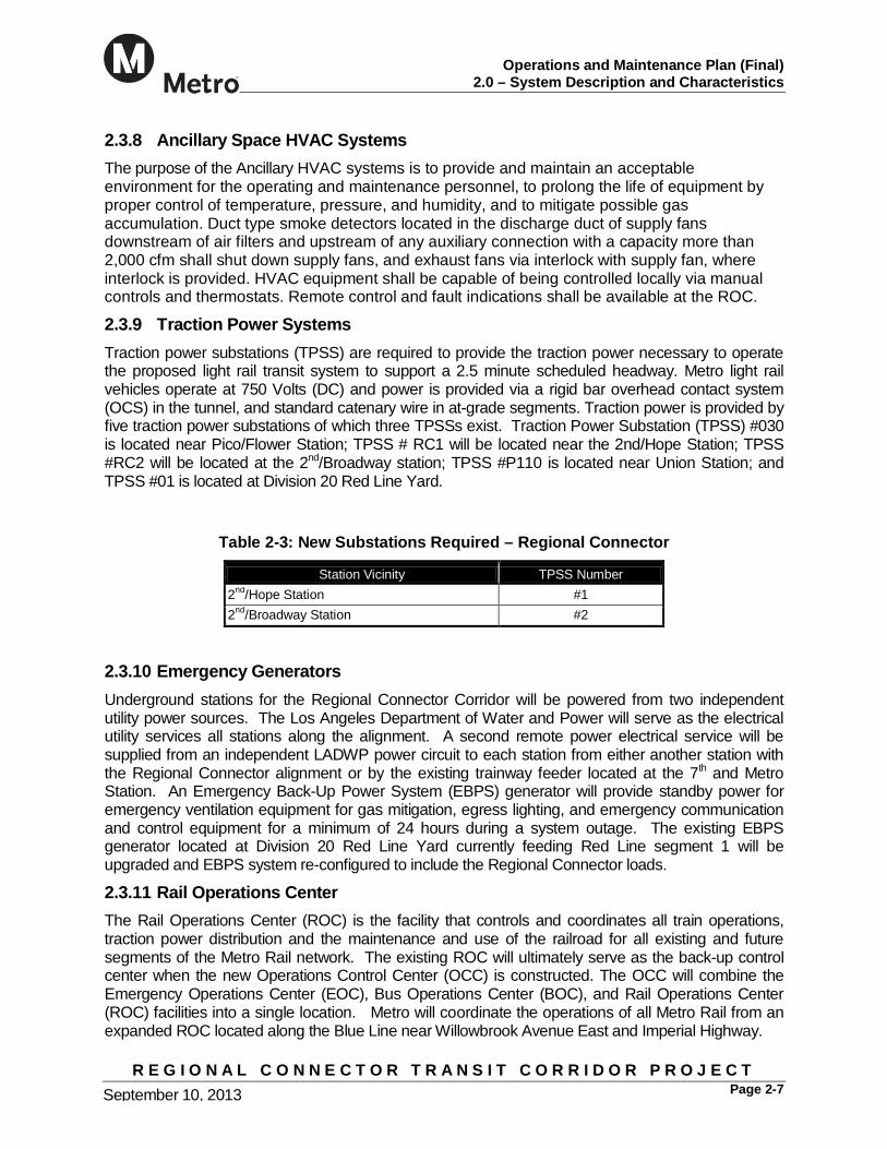
2.3.8 Ancillary Space HVAC Systems The purpose of the Ancillary HVAC systems is to provide and maintain an acceptable environment for the operating and maintenance personnel, to prolong the life of equipment by proper control of temperature, pressure, and humidity, and to mitigate possible gas accumulation. Duct type smoke detectors located in the discharge duct of supply fans downstream of air filters and upstream of any auxiliary connection with a capacity more than 2,000 cfm shall shut down supply fans, and exhaust fans via interlock with supply fan, where interlock is provided. HVAC equipment shall be capable of being controlled locally via manual controls and thermostats. Remote control and fault indications shall be available at the ROC.
2.3.9 Traction Power Systems Traction power substations (TPSS) are required to provide the traction power necessary to operate the proposed light rail transit system to support a 2.5 minute scheduled headway. Metro light rail vehicles operate at 750 Volts (DC) and power is provided via a rigid bar overhead contact system (OCS) in the tunnel, and standard catenary wire in at-grade segments. Traction power is provided by five traction power substations of which three TPSSs exist. Traction Power Substation (TPSS) #030 is located near Pico/Flower Station; TPSS # RC1 will be located near the 2nd/Hope Station; TPSS #RC2 will be located at the 2nd/Broadway station; TPSS #P110 is located near Union Station; and TPSS #01 is located at Division 20 Red Line Yard.
Table 2-3: New Substations Required – Regional Connector
Station Vicinity TPSS Number 2nd/Hope Station #1 2nd/Broadway Station #2
2.3.10 Emergency Generators Underground stations for the Regional Connector Corridor will be powered from two independent utility power sources. The Los Angeles Department of Water and Power will serve as the electrical utility services all stations along the alignment. A second remote power electrical service will be supplied from an independent LADWP power circuit to each station from either another station with the Regional Connector alignment or by the existing trainway feeder located at the 7th and Metro Station. An Emergency Back-Up Power System (EBPS) generator will provide standby power for emergency ventilation equipment for gas mitigation, egress lighting, and emergency communication and control equipment for a minimum of 24 hours during a system outage. The existing EBPS generator located at Division 20 Red Line Yard currently feeding Red Line segment 1 will be upgraded and EBPS system re-configured to include the Regional Connector loads.
2.3.11 Rail Operations Center The Rail Operations Center (ROC) is the facility that controls and coordinates all train operations, traction power distribution and the maintenance and use of the railroad for all existing and future segments of the Metro Rail network. The existing ROC will ultimately serve as the back-up control center when the new Operations Control Center (OCC) is constructed. The OCC will combine the Emergency Operations Center (EOC), Bus Operations Center (BOC), and Rail Operations Center (ROC) facilities into a single location. Metro will coordinate the operations of all Metro Rail from an expanded ROC located along the Blue Line near Willowbrook Avenue East and Imperial Highway.

Operations and Maintenance Plan (Final)
2.0 – System Description and Characteristics
R E G I O N A L C O N N E C T O R T R A N S I T C O R R I D O R P R O J E C T Page 2-8 September 10, 2013
2.3.12 Train Control System The Train Control system (including related on-board equipment) is fully integrated into the civil, facilities and other subsystem designs consistent with Metro Design Criteria. An Automatic Train Control (ATC) System and related equipment shall be provided. The ATC System provides for fully integrated operations of the new system with the existing Metro System, such that the train operation is seamless. The ATC system includes Automatic Train Protection (ATP). It shall be compatible, interoperable and similar to the existing ATP System installed on the Metro Blue and Gold Lines. The ATP System shall support the operational requirements of the Metro Light Rail Transit (LRT). A bi-directional manually operated with cab signal system, providing over-speed protection only on all tracks, in any direction and when operating over crossovers. Continuous speed control shall be by coded cab signals in the rails or loops through turnouts and crossovers.
The ATP System shall include applicable vital train detection, automatic train protection, interlocking control and all other systems and subsystems, whether specifically identified herein or not, necessary for train control system operation. The train control system shall interface with SCADA system for control requests from ROC and indications to ROC.
2.3.13 Communications System The Communications system is consistent with Metro’s Design Criteria and with the existing operations on Metro’s Expo, Blue, Green, and Gold Line LRT services. The Communications system comprises the following elements:
Supervisory Control and Data Acquisition Systems (SCADA)
Cable Transmission Systems (CTS)
Telephone Systems
Radio Systems
Emergency Management System
Closed Circuit Television Systems
Transit Passenger Information System (TPIS)
Uninterruptible Power Supply System for communications system
Seismic Detection System
Fire Alarm Detection System
Intrusion Detection Access Controlled System
Tunnel Portal Surveillance and Alarm System
Gas Detection and Alarm System

Operations and Maintenance Plan (Final)
2.0 – System Description and Characteristics
R E G I O N A L C O N N E C T O R T R A N S I T C O R R I D O R P R O J E C T Page 2-9 September 10, 2013
The existing Cable Transmission System (CTS) on the Gold Line will be modified to delete the existing Little Tokyo node. A new SONET ring will be added for Regional Connector with dual homing to the existing 7th/Metro and Union Station nodes. EMP at 7th/Metro Station will be modified to include changes related to ventilation.
2.3.14 Fare Collection System The fare collection system will be fully compatible with Metro’s Universal Fare System including fare boxes, point-of-sale devices, fare gates and ticket vending machines. The existing Fare Collection system will change significantly. This includes the basis of fare collection (either distance based or flat fare), and TAP requirement between lines.
2.3.15 Safety and Security Program The Regional Connector LRT Project Safety and Security Certification Plan (SSCP) has been developed in compliance with the California Public Utilities Commission (CPUC) General Order 164D “Rules and Regulations Governing State Safety Oversight of Fixed Guideway Rail Systems.” The safety program has been integrated with both the ongoing activities of the agency as well as with the planning and construction of new projects and services. For more information on Safety and Security Plan compliance, please review the Regional Connector LRT Project: Safety and Security Certification Plan, November 30, 2011.
2.3.16 Connections with the Metro Bus Network Metro Bus services, as well as a number of other bus service providers, connect with Metro Rail services, including the Metro Expo, Blue, Green, and Gold Line LRT services, at virtually all stations, and all existing and new Regional Connector Corridor stations in downtown Los Angeles. When a new rail line is introduced, changes to bus routes in the vicinity of that new line may be implemented to reduce duplication of services and to provide efficient and timely connections to and from rail stations.
Operations and Maintenance Plan (Final)
3.0 – Operations
R E G I O N A L C O N N E C T O R T R A N S I T C O R R I D O R P R O J E C T Page 3-1 September 10, 2013
3.0 OPERATIONS 3.1 Introduction The working Operating Plan enabled by the Regional Connector Project discontinues the existing Gold Line service pattern, continues all Blue Line trains from Long Beach through the Regional Connector toward Azusa (Montclair), and continues all Exposition Line trains from Santa Monica to East Los Angeles. The design of the Regional Connector will allow 3-car trains at a 5 minute Schedule Headway resulting in a 2.5-minute Schedule Headway in the trunk upon opening of the Regional Connector. The two lines that will be operated are: North-South Line - Service on the north-south line will consist of:
o Full-line operation from Downtown Long Beach on the Metro Blue Line to Azusa on the Metro Gold Line (or Montclair if Foothill Extension Phase 2B is implemented).
o The Blue Line will have short line turnback terminals at Willow in Long Beach and at Sierra Madre Villa in Pasadena.
East-West Line – Service on the east-west line will consist of full-line operation from East Los Angeles on the Metro Gold Line (or Whittier if Phase 2 of the Eastside Transit Corridor is implemented with the Washington Boulevard alternative) to Downtown Santa Monica..
3.2 Train Services The line extensions that comprise the overall project are in various stages of planning, engineering, or construction. The following assumptions and guidance have been used in developing the Conceptual Operating Plan: Run times from the existing Expo Line. Core area run times from the results of unimpeded RAILSIM simulations over the core
area under a 2.5 minute Schedule Headway. Run times from the existing Blue Line schedule from Downtown Long Beach to Grand
Station. Run times from the existing Gold Line schedule from Union Station to Sierra Madre Villa
Station. Estimated run times from Sierra Madre Villa Station to Azusa (or the future Montclair
Station if constructed), as provided by Metro Operations personnel. Estimated run times from the future Washington/Lambert Station to Atlantic Station (or
Whittier if constructed), as provided by Metro Operations personnel. Estimated run times from the future Downtown Santa Monica Station to Culver City, as
provided by Metro Operations personnel. Run times from Pico/Aliso Station to East Los Angeles Atlantic Station.
The proposed schedule was built such that trains of the same service (i.e. North-South or East-West) but opposite direction meet at the 1st/Central Wye Interlocking and Flower/Washington Interlocking. That is, train times at 1st/Central Wye interlocking and Flower/Washington Wye interlocking served as the ‘anchors’ for schedule development; this time was fixed for each train and the other scheduled

Operations and Maintenance Plan (Final)
3.0 – Operations
R E G I O N A L C O N N E C T O R T R A N S I T C O R R I D O R P R O J E C T Page 3-2 September 10, 2013
times were set accordingly based on simulated run times in the Core Area (Grand/23rd/Union/Pico-Aliso) and scheduled / estimated times outside the Core Area. Having trains of the same service pass at the Wye Interlocking prevents delays since two trains can make simultaneous moves through the interlocking. In coordination with Metro Operations, a proposed schedule was developed in accordance with the branch line headway requirements detailed in Table 3-1:
Table 3-1: Branch Line Headway Requirements
Time Range Requirement 4:30-5:00 Build from no service to 15 minute headways 5:00-6:00 Build from 15 minute headways to 5 minute headways 6:00-9:00 Peak period; maintain 5 minute headways 9:00-3:00 Ramp down to 10 minute headways, and maintain that for
the rest of this period 3:00-3:15 Build up to 5 minute headways 3:15-6:30 Peak period; maintain 5 minute headway
6:30-12:00a Ramp down to 10 minute headways and maintain that for the rest of this time period
12:00-12:15 Ramp down to 20 minute headways, ending service at 2:15a
3.2.1 Weekday Early Morning Service Frequency Service will begin at 4:30 AM and early morning service will continue until 5:00 AM. Service will operate at a 15-minute headway on the branch lines, resulting in a 7.5-minute headway in the Core Area. Between 5:00 AM and 6:00 AM service on the branch lines will ramp up to 5-minute headways in preparation for the morning peak hour service.
3.2.2 Weekday Peak Period Service Frequency The AM peak period begins at 6:00 AM and ends at 9:00 AM. The PM peak period begins at 3:00 PM and ends at 6:30 PM. Peak period service on the branch lines will run at 5-minute headways, resulting in a 2.5-minute headway in the Core Area. Because eastbound, westbound, northbound, and southbound trains would all provide service to downtown Los Angeles, service would operate at peak frequency in both directions on the East-West and North-South lines during the peak periods.
In the trunk section between the Washington/Flower and 1st/Alameda, which is served by both routes, the combined headway would be 2.5 minutes.
3.2.3 Weekday Mid-Day Service Frequency Weekday mid-day service runs approximately from 9:00 AM to 3:00 PM. After 9:00 AM, service will ramp down from the peak hour frequency on the branch lines to run at 10-minute headways, resulting in 5-minute headways in the Core Area. At approximately 3:00 PM service will ramp up

Operations and Maintenance Plan (Final)
3.0 – Operations
R E G I O N A L C O N N E C T O R T R A N S I T C O R R I D O R P R O J E C T Page 3-3 September 10, 2013
from 10-minute headways on the branch lines to 5-minute headways in anticipation of peak period operations.
3.2.4 Weekday Evening Service Frequency Beginning at approximately 6:30 PM, service frequency would ramp down to a 10-minute evening headway on both the East-West and North-South lines; the combined headway during the evening period would be 5 minutes. The evening headway would continue until midnight, when the frequency would ramp down to a 20-minute headway (10-minute headway in the trunk), which would be maintained until the end of service at 2:15 AM.
3.2.5 Weekday Late Night Service Frequency Weekday late night service runs from 12:30 AM to 2:15 AM. Service will operate at a 20-minute frequency on the branch lines, resulting in a 10-minute headway in the Core Area. The last trains will depart terminals at approximately 2:15 AM.
3.2.6 Weekend/Holiday Service Frequency Weekend and Holiday service will run from approximately 4:30 AM to 9:00 AM with a 15-minute headway, increasing to a 12-minute headway from 9:00 AM to 11:00 AM, and to 7.5 minutes from 11:00 AM to 8:00 PM. In the evenings from 8:00 PM to 12:00 AM, there will be a 10-minute headway, and a 20-minute headway from 12:00 AM to 2:15 AM.
3.3 Travel Times The run times used for developing the schedule were based on RAILSIM® simulation of the Core Area, existing scheduled run times outside the Core Area to the existing stations, and estimated run times to future stations that are either under construction or in the planning phases.
3.3.1 Travel Times between Stations Table 3-2 and Table 3-3 contain the simulated run times between 23rd Street and Mariachi Plaza, and between San Pedro and Union. A representative diagram of the Core Area is included for reference in Appendix A.

Operations and Maintenance Plan (Final)
3.0 – Operations
R E G I O N A L C O N N E C T O R T R A N S I T C O R R I D O R P R O J E C T Page 3-4 September 10, 2013
Table 3-2: Simulated Running Times: 23rd Street –Mariachi Plaza
Station/Interlocking Name Interval Time Dwell Time Total Run Time 23rd Street 0:00:00 0:00:20 0:02:04 Pico 0:02:29 0:00:40 0:04:33 7th-Flower 0:01:55 0:00:40 0:06:28 2nd-Hope 0:01:47 0:00:20 0:08:15 2nd-Broadway 0:01:32 0:00:20 0:09:47 1st-Central 0:01:48 0:00:40 0:11:35 Pico-Aliso 0:02:31 0:00:20 0:14:06 Mariachi Plaza 0:01:17 0:00:20 0:15:23 Mariachi Plaza 0:00:00 0:00:20 0:00:20 Pico-Aliso 0:01:18 0:00:20 0:01:38 1st-Central 0:03:19 0:00:40 0:04:57 2nd-Broadway 0:01:29 0:00:20 0:06:26 2nd-Hope 0:01:34 0:00:20 0:08:00 7th-Flower 0:02:08 0:00:40 0:10:08 Pico 0:02:01 0:00:40 0:12:09 23rd Street 0:02:09 0:00:20 0:14:18

Operations and Maintenance Plan (Final)
3.0 – Operations
R E G I O N A L C O N N E C T O R T R A N S I T C O R R I D O R P R O J E C T Page 3-5 September 10, 2013
Table 3-3: Simulated Running Times: San Pedro - Union Station/Interlocking Name Interval Time Dwell Time Total Run Time San Pedro 0:00:00 0:00:20 0:00:20 Grand 0:02:12 0:00:20 0:02:32 Pico 0:02:40 0:00:40 0:05:12 7th-Flower 0:01:55 0:00:40 0:07:07 2nd-Hope 0:01:47 0:00:20 0:08:54 2nd-Broadway 0:01:32 0:00:20 0:10:26 1st-Central 0:01:48 0:00:40 0:12:14 Union 0:03:10 0:00:30 0:15:24 Union 0:00:00 0:00:30 0:00:30 1st-Central 0:03:32 0:00:40 0:04:02 2nd-Broadway 0:01:29 0:00:20 0:05:31 2nd-Hope 0:01:34 0:00:20 0:07:05 7th-Flower 0:02:08 0:00:40 0:09:13 Pico 0:02:01 0:00:40 0:11:14 Grand 0:02:19 0:00:20 0:13:33 These one-way travel time estimates are based on the following assumptions:
• All East-West trains (except equipment moves to and from the yards) operate of the full length of the route between Downtown Santa Monica and East Los Angeles Atlantic (or Whittier - Washington/Lambert, if constructed).
• During the morning and evening peak periods, alternate North-South trains operate on the “short route” between Willow Street and Sierra Madre Villa, while the remaining trains operate of the “long route” between the Downtown Long Beach and Azusa (Montclair if constructed). All North-South trains operate on the long route during off-peak periods.
• Operating speeds take into account permanent civil speed restrictions such as grades, curvature and track super-elevation, the design and layout of crossovers, and the time it takes to move through them as well as other operational restrictions
• Speed restrictions imposed by the signal and train control system and California Public Utilities Commission (CPUC) regulation
• Maximum design speed is 45 miles per hour in mixed traffic area • Station dwell times. This is the amount of time that a train is stopped at a station for
passengers to alight and board. The scheduled dwell time ranges from 20 seconds to 40 seconds, depending on the ridership volume at a particular station. Most stations have a scheduled dwell of 20 seconds.

Operations and Maintenance Plan (Final)
3.0 – Operations
R E G I O N A L C O N N E C T O R T R A N S I T C O R R I D O R P R O J E C T Page 3-6 September 10, 2013
Scheduled terminal “turn-around” times (when Train Operators change from one end of the train to the other for the return trip) will be no less than 3.0 minutes, allowing recovery capability for only a very minor service delay. Normally, a second train will be ready to depart at terminal upon arrival of the first train. This allows for better schedule reliability. The turn-around time for various levels of service delivery is also subject to headway cycle and clearance “slots” at interlockings, where trains must use the available opportunities for their movements to keep in the proper cycle. For East-West trains, the end-to-end travel time is approximately 1 hour and 24.5 minutes eastbound and 1 hour and 25 minutes westbound. Cycle times vary, depending on the headway being operated. During peak periods (5-minute branch headway) the cycle time is 2 hours 59 minutes to 3 hours 5 minutes. Cycle time during mid-day service (10-minute branch headways) is between 3 hours and 3 hours 10 minutes, and during night service (20 minute branch headways) is 2 hours 59 minutes. For North-South trains on the long route between Long Beach Transit Mall and Montclair, the end-to-end travel time is approximately 2 hours 9 minutes in both directions. Cycle times vary, depending on the headway being operated. During peak periods (5-minute branch headway) the cycle time is 4 hours 33.5 minutes to 4 hours 40 minutes. Cycle time during mid-day service (10-minute branch headways) is 4 hours 35 minutes, and during night service (20 minute branch headways) is 4 hours 25.5 minutes. For North-South trains on the short route between Willow Street and Sierra Madre Villa, the end-to-end travel time is approximately 1 hour 18 minutes northbound and 1 hour 17.5 minutes southbound. Cycle time for this route, which operates only during peak hours, is 2 hours 50 minutes. Tables 3.4 and 3.5 present the travel times for the East-West and North-South Lines, respectively. The times for line segments not currently in operation are approximate and subject to confirmation.
Table 3-4: Estimated Travel Times Between Stations – East-West Line
Station Name Travel Time Dwell Time Total
Time Travel Time Dwell Time Total
Time Downtown Santa Monica N/A N/A 0:00:00 0:38:00 N/A 1:24:58 23rd Street 0:37:40 0:00:20 0:38:00 0:01:49 0:00:20 0:46:58 Pico 0:01:49 0:00:40 0:40:29 0:01:21 0:00:40 0:44:49 7th St/Metro Ctr 0:01:15 0:00:40 0:42:24 0:01:28 0:00:40 0:42:48 2nd Pl/Hope 0:01:27 0:00:20 0:44:11 0:01:14 0:00:20 0:40:40 2nd St/Broadway 0:01:12 0:00:20 0:45:43 0:01:09 0:00:20 0:39:06 1st St/Central 0:01:08 0:00:40 0:47:31 0:02:39 0:00:40 0:37:37 Pico-Aliso 0:02:11 0:00:20 0:50:02 0:00:58 0:00:20 0:34:18 Mariachi Plaza 0:00:57 0:00:20 0:51:19 0:32:40 0:00:20 0:33:00 Washington/ Lambert
0:33:00 N/A 1:24:19 N/A N/A 0:00:00
Total (Depart to Arrive) 1:20:39 0:03:40 1:24:19 1:21:18 0:03:40 1:24:58

Operations and Maintenance Plan (Final)
3.0 – Operations
R E G I O N A L C O N N E C T O R T R A N S I T C O R R I D O R P R O J E C T Page 3-7 September 10, 2013
Table 3-5: Estimated Travel Times Between Stations – North-South Line
Station Name Travel Time Dwell Time Total
Time Travel Time Dwell Time Total Time
Downtown Long Beach N/A N/A 0:00:00 0:15:00 N/A 2:09:03 Willow St 0:14:40 0:00:20 0:15:00 0:33:33 0:00:20 1:54:03 San Pedro St 0:33:28 0:00:20 0:48:48 0:1:47 0:00:20 1:20:10 Grand 0:01:52 0:00:20 0:51:00 0:01:59 0:00:20 1:18:03 Pico 0:02:00 0:00:40 0:53:40 0:01:21 0:00:40 1:15:44 7th St/Metro Ctr 0:01:15 0:00:40 0:55:35 0:01:28 0:00:40 1:13:43 2nd Pl/Hope 0:01:27 0:00:20 0:57:22 0:01:14 0:00:20 1:11:35 2nd St/Broadway 0:01:12 0:00:20 0:58:54 0:01:09 0:00:20 1:10:01 1st St/Central 0:01:08 0:00:40 1:00:42 0:02:52 0:00:40 1:08:32 Union Station 0:02:40 0:00:30 1:03:52 0:28:30 0:00:30 1:05:00 Sierra Madre Villa 0:28:40 0:00:20 1:32:52 0:35:40 0:00:20 0:36:00 Montclair 0:36:00 N/A 2:08:52 N/A N/A 0:00:00 Total (Depart to Arrive) 2:04:22 0:04:30 2:08:52 2:04:33 0:04:30 2:09:03
3.3.2 Accommodating the Elderly and Disabled The compliance to the ADAAG is mandatory by the law and the Metro Rail Design Criteria. The design and construction of the stations shall comply with Americans with Disabilities Act Accessibility Guidelines (ADAAG) and California Title 24 CCR. The specific technical standards and codes applicable to specific design and construction are listed in Metro Design Criteria Section 6. Operations personnel must be aware of the particular needs of elderly passengers and those with disabilities during both irregular and single-track operations. Circumstances may well require supervisory personnel, security personnel and/or others at side-platform stations to assist passengers and expedite train operations where possible. Special signage and/or operating or other personnel positioned at the sidewalk entrance to those side-platform stations is required to properly direct passengers to the proper platform during single-track operations. Assistance in the proper time and location effectively mitigates train delay issues encountered from having to wait for passengers moving from one platform to the other. Delays that occur at stations to accommodate the elderly and those with disabilities increase station dwell times and further increase the running times between interlockings described in the paragraphs above. For these reasons, operating personnel are required to be especially attentive to the special needs that will occur at side-platform stations during single-track operations, deploying additional resources as necessary.
3.3.3 Estimated Run Times Run times to Montclair, Washington-Lambert and Colorado/4th were provided by Metro in Table 3-6 as follows:

Operations and Maintenance Plan (Final)
3.0 – Operations
R E G I O N A L C O N N E C T O R T R A N S I T C O R R I D O R P R O J E C T Page 3-8 September 10, 2013
Table 3-6: Estimated Running Times
Location 1 Location 2 Running Time (minute) Mariachi Plaza Washington-Lambert 33
Colorado/4th 23rd Street 38 Sierra Madre Montclair 36
3.3.4 Train Operations Metro Blue Line schedule run times were based on the Monday through Friday schedules effective July 17, 2011. The Gold Line schedule run times were based on the Monday through Friday schedules effective June 26, 2011. The run times used from existing Metro Blue Line and Metro Gold Line schedules follow in Table 3-7:
Table 3-7: Existing Schedule Running Times
Location 1 Location 2 Running Time (minute) Long Beach Transit Mall Grand Avenue Station 51
Willow Station Grand Avenue Station 36 Union Station Sierra Madre Villa Station 29
3.4 Regional Connector Operations 3.4.1 Pre-Revenue Operations – Regional Connector Pre-Revenue Operations (PRO) takes place, as the last rail activation element of the project, after System Integration Testing has been completed. PRO is scheduled for approximately 60 days. The start-up date of revenue train operations for the public will immediately follow completion of PRO.
Regional Connector will have a two-phased opening for Revenue Train Operations. Phase I will open/extend the line from 7th/Metro to East Los Angeles, and Phase II will open the remaining branch line from 1st/Central Station to Union Station. Hence, two PRO will be done accordingly for each phase.
Prior to PRO, vehicles, communications, switches, automatic train control, and other service and operational elements are tested and validated. Once these tests conclude, PRO initiates. During PRO, schedules are tested, evaluated and adjusted under simulated operating conditions. Service interruption scenarios and emergency response activities are practiced. Intra- and inter-agency familiarization takes place.
Satisfactory completion of the Pre-Revenue Operations will provide the basis for certifying that the system is capable of providing a safe and dependable rail service. This is the period of time where all of Metro’s operating rules, procedures during normal, abnormal and emergency conditions, maintenance practices, reporting mechanisms, etc. are tested and refined. It is at

Operations and Maintenance Plan (Final)
3.0 – Operations
R E G I O N A L C O N N E C T O R T R A N S I T C O R R I D O R P R O J E C T Page 3-9 September 10, 2013
this time that the Emergency Drills are to be conducted.
3.4.2 Train Operations Each Metro LRT train is operated by a single Train Operator. There are no other crew members.
3.4.3 Duty Assignments All LRT Train Operator assignments are developed by the Service Planning Scheduling Department. Train Operators submit bids for the duty assignments they prefer and are selected to work assignments in accordance with the terms of collective bargaining agreements that are in effect. Some operators are assigned to take custody of trains and place them into service or bring them back from service. Some Train Operators relieve others already in service and may or not handle trains to and from the yard. Other Train Operators are assigned to “work as directed,” providing staffing for logistical train movements, mainline replacement, test or extra trains and emergency operator replacement. Besides the number of Train Operator assignments needed to provide scheduled and logistical service, an additional number of extra or relief operators are required to cover Train Operator vacations and sick days and to provide coverage for other vacancies that may occur. Because Train Operator duty assignments can change frequently as operating patterns are revised, the actual assignments are not included as a part of this document.
3.5 Train Consists Operations planning estimates and assumptions are based on the operation of 3-car consists. The three new stations will include platforms to serve three-car LRT vehicles. Trains can be assigned from 1 to 3 cars, depending on ridership conditions.
3.6 Terminal Dwell Times In accordance with Metro’s Operations Design Criteria, the turn times used at all the end-terminals and in-line terminals are not less than three (3) minutes, allowing for adequate time to change train operators and recovery capability for only a very minor service delay. Typically, as a train arrives at a terminal, another train is ready to depart; effectively increasing the schedule recovery capability by one full headway.

Operations and Maintenance Plan (Final)
3.0 Operations
R E G I O N A L C O N N E C T O R T R A N S I T C O R R I D O R P R O J E C T Page 3-10 September 10, 2013
3.7 Station Dwell Times & Other Simulation Parameters The Station dwell times and other RAILSIM® parameters used for the Core Area simulation per previous direction from an agreement with Metro and CPJV are detailed in Table 3-8 below.
Table 3-8: Simulation Parameters Parameter Description Setting Station Stop and Civil Speed Comfort Margins
Braking comfort margin is the percent by which the brake rate specified in the equipment data is reduced (made gentler), requiring that trains initiate braking sooner in the simulation in order to make their station stop or to reach their civil speed target.
10%
Acceleration Reaction Time
The train operator and equipment reaction time to accelerate the train in response to an upgraded signal or cab code rate. 6 seconds
Deceleration Reaction Time
The train operator and equipment reaction time to brake the train after seeing a downgraded signal or cab code rate. 6 seconds
Jerk Rate The maximum rate of positive (or negative) change in acceleration. A lower value will cause acceleration to increase (or decrease) more gradually.
2.0 mph/s2
Maximum Brake Rate The equipment maximum brake rate 2.5 mph/s
Passenger Load The constant number of passengers assumed during the entire run:
(light standee/ AW2 load)
170 per car; 510 per train
System Maximum Design Speed
The maximum system speed 45 mph
Traffic Intersections Delay at traffic intersections 0 seconds
Signal Aspect Relay Movement Time
The time for “downstream” signals to update 0 seconds
Station Dwell Time
23rd Street, San Pedro, Grand, Pico/Aliso and Mariachi Plaza, 2nd/Hope and 2nd/Broadway
20 seconds
Station Dwell Time Union 30 seconds
Station Dwell Time Pico, 7th/Metro, 1st/Central 40 seconds
Interlocking Processing
Interlocking Processing times at Washington/Flower Switch Movement Time Route Establishment Time Route Release Time
5 seconds 3 seconds 5 seconds
Interlocking Processing
Interlocking Processing times at 1st -Central Switch Movement Time Route Establishment Time Route Release Time
5 seconds 3 seconds 5 seconds

Operations and Maintenance Plan (Final)
4.0 Wayside Systems Maintenance
R E G I O N A L C O N N E C T O R T R A N S I T C O R R I D O R P R O J E C T Page 4-1
4.0 WAYSIDE SYSTEMS MAINTENANCE
4.1 Management and Supervision The Wayside Systems departments are responsible for Track, Communications and Signals, Traction Power, Facilities Maintenance/Custodial Services, SCADA Systems Engineering and Maintenance, and Maintenance of Way Systems Engineering. Responsibilities encompass all required inspections, preventive maintenance, corrective maintenance, emergency response, and system design and improvements. These departments are also responsible for rail system infrastructure preservation.
As portions of the systems start to age, every effort is made to protect the investment. Examples of this work include track maintenance and repair, rail profile grinding, signal repair and replacement, grade crossing rehabilitation, traction power system renewal and upgrades. These programs are necessary to support the Rail Operations overall goal of operating and maintaining a safe, clean and efficient transit system with professionalism, courtesy and integrity throughout the Los Angeles region.
The Wayside Systems Department is currently divided into eight units that directly support the Metro Rail System:
Track
Signals
Traction Power
Rail Communications
Rail Facilities Maintenance / Custodial Services
SCADA Systems Engineering and Maintenance
Transit Systems Engineering
Maintenance of Way (MOW) Engineering
The Track, Signals, Traction Power and Wayside Engineering Departments report to the Executive Officer – Wayside Systems. Rail Communications, Transit Systems Engineering and SCADA Systems Engineering and Maintenance report to the Executive Officer – Rail Transit Engineering and Maintenance. Both EOs report directly to the General Manager – Rail Operations. The Wayside System Organization Charts are presented below.
The Wayside Systems Department personnel are currently stationed at five base locations dispersed throughout the rail system network as follows:
Location 61 adjacent to the Division 20 Facility (Signals, Traction Power, Wayside Engineering)
Division 20 Facility (Custodial)
Location 62 (Rail Communications)
Location 66 near to the Rail Operations Control Center (Track)

Operations and Maintenance Plan (Final)
4.0 Wayside Systems Maintenance
R E G I O N A L C O N N E C T O R T R A N S I T C O R R I D O R P R O J E C T Page 4-2
Location 60 Central Control Facility (which houses the ROC, SCADA engineering staff and a component of the custodial staff).
Included in the preventive maintenance program are periodic inspection and maintenance tasks, which have been established to meet the Metro’s needs. The scope and frequency of these tasks are based on the following criteria:
System safety
Regulatory requirements
Manufacturers’ recommendations
Agency experience
Budget constraints
An overall Wayside Systems Maintenance Plan is currently under development and will detail the inspection and maintenance operations, along with the procedures for conducting them. A brief summary of each of the maintenance areas, with department-specific Maintenance Plans noted as applicable is contained in the following sub-sections.

Operations and Maintenance Plan (Final)
4.0 Wayside Systems Maintenance
R E G I O N A L C O N N E C T O R T R A N S I T C O R R I D O R P R O J E C T Page 4-3
4.2 Track Figure 1 below presents the Track Department Organizational Chart.
Figure 4-1 Track Systems Maintenance
The track of the Metro Rail System is maintained by the Wayside Systems Department in accordance with the programs defined in the Department’s Track Maintenance Program, June 2005. The plan complies with established industry guidelines as well as Federal and State regulations. Inspection and maintenance is performed using tested and reliable methods. CPUC General Order 143-B, Section 14.05 requires formal inspection, maintenance and reconstruction programs, A systematic inspection and maintenance program has been established to ensure the safety of the riding public and Metro Rail employees.
All Metro Rail track is inspected and maintained in accordance with the Federal Railroad Administration Track Safety Standards as contained in Title 49 CFR Part 213. It is Metro Rail’s policy to maintain its track to a standard that is one Federal Railroad Administration (FRA) track class higher than is required by the maximum operating speed for any given segment of track. Reconstruction work is performed in accordance with American Railway Engineering and Maintenance-of-Way Association (AREMA) Standards as required by CPUC General Order 143-B, Section 9.01.
Track inspection is performed by trained and certified track inspectors to identify potential safety hazards and to report on the changing condition of the track geometry. Main tracks are required to be inspected twice weekly with at least a one-day interval between the inspections. Yard tracks are inspected weekly. Written track inspection reports are completed by the track

Operations and Maintenance Plan (Final)
4.0 Wayside Systems Maintenance
R E G I O N A L C O N N E C T O R T R A N S I T C O R R I D O R P R O J E C T Page 4-4
inspectors documenting the location, track, nature, and extent of the defects and conditions observed. Reports also contain repair date, action taken, and the name of the person making the repairs to minor defects at the time of the inspection.
Defects that cannot be repaired by the inspectors at the time of inspection are considered major defects, requiring additional resources and/or long-term maintenance program and planning to remedy.
The following are examples of the items that are included in an inspection:
Track Structure: All ballasted track, direct fixation track, embedded track, grade crossings and special track work sections are inspected for appropriate fit of all components including track switch points, and moving parts.
Fastening Systems: Direct fixation bolts and rail clips, spikes, joint bars and rail anchors are inspected for tightness.
Track Geometry: Track gauge, alignment, cross-level, super-elevation, as well as ballast and sub-grade conditions are inspected to determine that they are within in acceptable tolerances.
Deterioration: Excessive or unusual wear of rail, ties, bolts, joint bars, frog inserts, switch points, rail welds, and other appurtenances is identified by measuring and evaluating in accordance with the requirements and tolerances or each component. Such inspections also include identifying vegetation growth and right-of-way encroachments or infringements.
Extreme Hot Weather Conditions: When temperatures reach 105 degrees Fahrenheit, all tracks, except subway tracks, are inspected for hot weather related damage or indications of excess thermal expansion.
Severe Weather: Storms with heavy rains or damaging winds, or other occurrences including fires and/or seismic events, are cause for special track inspections to determine that the railroad is safe for train operations.
Accident Damage: Damage can occur to track as a result of train collisions and/or derailments, dragging equipment, accidents at grade crossings and other events. Inspections are made in response to request from the ROC following such incidents.
The Track Maintenance Program provides detailed instructions for each type of inspection including the standards and tolerances to be met, the forms to be used, the type or repair and/or corrective actions required for each situation, the materials and procedures to be used, and the record-keeping requirements.
As with other maintenance tasks that involve the active railroad, the Track Department must perform a significant amount of its work during the limited non-revenue service hours. This requires special coordination and flexible work schedules, with personnel and equipment availability sufficient to accomplish the required work in the time period available. In many cases, the work can be accomplished without adversely affecting scheduled train service.
Other work of longer duration or involving interlockings for example, can involve taking sections of track or interlockings out of service while repair and/or reconstruction work is done. The Track Department coordinates its plans and activities closely with various Rail Operations Departments, including Transportation, Rail Operations Control, and Scheduling. In some

Operations and Maintenance Plan (Final)
4.0 Wayside Systems Maintenance
R E G I O N A L C O N N E C T O R T R A N S I T C O R R I D O R P R O J E C T Page 4-5
circumstances, single-track train operations are required to provide sufficient time for the necessary work to be performed.
The Track Department maintains the required records of inspection and maintenance and makes them available to the CPUC for review and audit.
4.3 Rail Communications Figure 2 below presents the Rail Communications Department Organization Chart.
Figure 4-2 Rail Communications Systems
The Rail Communications Department installs and maintains the rail system telephone and radio communications systems on the Metro Rail system. The following communications systems are applicable to the Regional Connector:
Maintenance Telephones (MT)

Operations and Maintenance Plan (Final)
4.0 Wayside Systems Maintenance
R E G I O N A L C O N N E C T O R T R A N S I T C O R R I D O R P R O J E C T Page 4-6
Emergency Telephones at Traction Power Substations (TPSSs)
Emergency Telephones at Blue Light Stations (BLS)
Emergency Telephones at Platforms (ET)
Elevator Telephones
Fire Alarm Systems (FAS)
Supervisory Control and Data Acquisition (SCADA)
Passenger Assistance Intercom Systems at stations
Transit Passenger Information System (TPIS) at passenger stations
Seismic Detection System (SDS)
Gas Detection and Alarm System Cable Transmission System (CTS)
Radio channel for train operations
Multi-transmitter system radio channel for Systems Maintenance
Tunnel radio system including fire/police channel connections
Station Communications Uninterruptable Power Supply (UPS)
Intrusion Detection Access Controlled System (IDACS)
Tunnel Portal Surveillance and Alarm System
Emergency Management System (EMS)
Remote terminal Unit (RTU)
There are other communications systems at Metro to serve the agency’s administrative functions. However those are not installed and maintained by the Rail Communications Department within Metro Rail Operations.
Inspection and maintenance of the radio and telephone systems listed above, and the devices connected to them, are carried out at specific intervals in accordance with manufacturers’ recommendations and, where applicable, in accordance with the requirements of the Federal Communications Commission (FCC) and the CPUC. The details of the inspection and maintenance requirements and procedures are contained in the Department’s Preventive Maintenance Plan for Rail Communications, Version 3.1 (April 23, 2008). The Rail Communications Department maintains records of the required inspections and maintenance and makes them available to the FCC and the CPUC for review and audit.
Most of the radio transmitter locations that serve the Metro Rail System are located on hilltops within the Los Angeles Metropolitan area and they are not immediately adjacent to the Metro Rail mainline rights-of-way. New radio base station antenna located in close proximity to the station entrance is required to re-broadcast the LA Metro (MTA), LA police, LA sheriff and fire department in stations and tunnels.
The Communications Department works closely with the SCADA Engineering and Maintenance Department to manage the interfaces between the communications and train control systems.

Operations and Maintenance Plan (Final)
4.0 Wayside Systems Maintenance
R E G I O N A L C O N N E C T O R T R A N S I T C O R R I D O R P R O J E C T Page 4-7
4.4 Signals Figure 3 below presents the Signals Department Organizational Chart.
Figure 4-3 Signal System Maintenance
The Signals Department installs and maintains the wayside signal and train control systems on the Metro Rail System. It does not install or maintain the signal equipment mounted on the light rail vehicles.
The Train Control system for the Regional Connector will fully integrate with Metro’s civil, facilities and other subsystem designs in accordance with Metro Design Criteria and the overall operation of Metro’s light rail and heavy rail network.
The following signal systems are in place on the Metro’s light rail network:
Automatic Train Control System
Wayside and Cab Signal System
Signal track circuitry and associated equipment
The Signal System Maintenance Plan, August 2008, contains both the preventive and the corrective portions of the signal maintenance program. The Plan meets regulatory requirements and industry standards while taking into account the maintenance recommendations of the signal equipment manufacturers as well as the maintenance experience of the Metro Rail Operations Signal Department.

Operations and Maintenance Plan (Final)
4.0 Wayside Systems Maintenance
R E G I O N A L C O N N E C T O R T R A N S I T C O R R I D O R P R O J E C T Page 4-8
Signal maintenance includes the periodic inspection, testing, and performance of both scheduled and corrective maintenance to insure the proper and safe operation of the signal system. The scope of signal maintenance includes interlockings, mainline train control, conventional and audio track circuits, audio overlay track circuits, grade crossing warning systems, centralized traffic control, preemption of traffic signals, and yard signal systems. The core of this system includes the testing, adjustment, and repair of vital relay circuitry, logic networks, preemption equipment, relay logic control limit circuits for protection against following trains, power supply and transfer networks, grade crossing interfaces, and all the relevant and peripheral appurtenances and signal appliances.
The Signal System Maintenance Plan contains the detailed inspection intervals and checklists, including the test procedures for the systems and equipment listed above. Signal Supervisors oversee the work of signal maintainers and other signal department personnel. The requirements of the plan are closely adhered to in order to achieve the required levels of safety and operational performance required by the Metro Rail system.

Operations and Maintenance Plan (Final)
4.0 Wayside Systems Maintenance
R E G I O N A L C O N N E C T O R T R A N S I T C O R R I D O R P R O J E C T Page 4-9
4.5 Traction Power Figure 4 below presents the Traction Power Department Organizational Chart.
Figure 4-4 Traction Power
The Traction Power Department is responsible for maintaining:
Traction Power Substations
Overhead Contact System
Station Power Systems
Ventilation Power
Universal Power Supply
Station and Tunnel Inspections

Operations and Maintenance Plan (Final)
4.0 Wayside Systems Maintenance
R E G I O N A L C O N N E C T O R T R A N S I T C O R R I D O R P R O J E C T Page 4-10
The traction power distribution system consists of three components: substations, auxiliary distribution, and the DC distribution systems. The Regional Connector project will introduce the use of an overhead conductor rail system (rigid OCS), which is the first use of this equipment for Metro. The Wayside Systems Traction Power Maintenance Plan, March 19, 2009, defines in detail all the procedures for the operation and maintenance of the traction power network. The Plan identifies all the equipment within each system and meets the maintenance needs of each of those systems. An update to the Plan is required to include the procedures for operations and maintenance of rigid OCS, which will necessarily require additional training for operations and maintenance staff. The operation and maintenance procedures defined in the plan are designed to achieve the highest degree of safety and dependability for the system, based on a combination of the manufacturer’s recommendations and the agency’s experience.
The basic preventive maintenance program is divided into two parts; the first part is the required or safety related maintenance which is performed on exact schedules; the second part consists of those inspections and procedures that when completed within a prescribed time frame, ensure a safe, economical, and reliable operation.
To achieve the operational support and maintenance goals, the personnel of the traction power department maintain a flexible operating schedule. This schedule provides response coverage during the hours of revenue operations while maximizing the efficiency of scheduled maintenance activities during the non-revenue hours. This is particularly critical due to the small non-revenue window available for traction power maintenance. The plan is implemented by scheduling the maintenance force in the most effective manner. This is done with overlapping shifts of maintainers that can concentrate their efforts as required by maintenance schedules.
The Traction Power Department participates in extensive in-house training and in the accident and disaster practice scenarios that are implemented by the Corporate and Rail Safety Departments and the Rail Activation Group.
Los Angeles Department of Water and Power would provide energy for the proposed traction power substations at the 2nd/Hope Station and the 2nd/Broadway Station.

Operations and Maintenance Plan (Final)
4.0 Wayside Systems Maintenance
R E G I O N A L C O N N E C T O R T R A N S I T C O R R I D O R P R O J E C T Page 4-11
4.6 Facilities Maintenance and Custodial Systems Figure 5 below presents the Facilities Maintenance and Custodial Services Department Organization Chart.
Figure 4-5 Rail Maintenance Custodial Services
The Director of Facilities Maintenance and Custodial Services has the responsibility for the maintenance of the right-of-way, stations, bridges and other structures, maintenance shop facilities, passenger stations, Wayside Systems facilities, and roadways for the Metro Rail System.
The Facilities Maintenance Department performs the regulated, mandated, preventive and corrective maintenance and repairs needed to maintain the right-of-way, stations, buildings, and shop facilities of the Metro Rail System, as set forth in the Facilities Maintenance Preventive Maintenance Plan, March 1, 2009.
The Custodial Services Department provides the custodial services for all Metro Rail passenger stations, buildings and facilities. Tasks are detailed in the Wayside Custodians Standard Operating Procedures Handbook - 2003. Each specific SOP is updated as necessary.

Operations and Maintenance Plan (Final)
4.0 Wayside Systems Maintenance
R E G I O N A L C O N N E C T O R T R A N S I T C O R R I D O R P R O J E C T Page 4-12
4.7 SCADA Systems Engineering and Maintenance Figure 6 below presents the SCADA Systems Engineering and Maintenance Department Organizational Chart. This group maintains the communications between equipment in the field and the ROC. This includes gathering data from equipment to support maintenance.
Figure 4-6 Rail Transit SCADA System
The existing LRT SCADA system is located at the Rail Operations Center. The LRT SCADA system, along with the remote terminal units, provide system interface with wayside safety equipment and existing train control systems.

Operations and Maintenance Plan (Final)
4.0 Wayside Systems Maintenance
R E G I O N A L C O N N E C T O R T R A N S I T C O R R I D O R P R O J E C T Page 4-13
4.8 Transit Systems Engineering Figure 7 below presents the Transit Systems Engineering Department Organizational Chart.
Figure 4-7 Transit Systems Engineering

Operations and Maintenance Plan (Final)
4.0 Wayside Systems Maintenance
R E G I O N A L C O N N E C T O R T R A N S I T C O R R I D O R P R O J E C T Page 4-14
4.9 Maintenance of Way Systems Engineering Figure 8 below presents the Maintenance of Way Systems Department Organizational Chart.
Figure 4-8 Maintenance of Way Engineering
The Maintenance of Way Engineering Department supports the Track, Traction Power and Signals Departments with systems design, evaluation and testing oversight for both in-service and proposed rail projects.
Current maintenance procedure and schedule will require augmentation to include the Regional Connector. Single tracking operation will likely be employed to accomplish the maintenance of the system with the 24/7 operating schedule.

Operations and Maintenance Plan (Final)
5.0 – Rail Fleet and Rail Fleet Services
R E G I O N A L C O N N E C T O R T R A N S I T C O R R I D O R P R O J E C T Page 5-1
5.0 RAIL FLEET AND RAIL FLEET SERVICES
5.1 Description of Metro Light Rail System Fleet Metro operates light rail service on the Blue and Gold Lines from the existing fleet of 171 LRT) vehicles.
5.1.1 Fleet Interchangeability The key findings of the in-service train requirements analysis indicate a total of eighty-one (81) trainsets are required to operate the North-South Line from Long Beach Transit Mall to Montclair and the East-West Line from Washington/Lambert to Colorado/4th. Of the eighty (81) total trainsets required: Forty-five (45) trainsets are required to operate the service on the North-South Line.
- Twenty-seven (27) of the forty-five (45) trainsets on the North-South Line are required to operate the long-line service from the Downtown Long Beach to Azusa (or Montclair, if constructed) and eighteen (18) of the forty-five (45) trainsets are required to operate the short-line service from Willow Station to Sierra Madre Villa Station.
Thirty-six (36) trainsets are required to operate the service on the East-West Line.
The light rail fleet in use on current Blue and Gold Line operations and those that will serve the Regional Connector Corridor Core Area will be stored and maintained at the Santa Monica, Division 11, Washington storage siding, Division 21, and Monrovia yards.
5.1.2 Rail Fleet Management Plan Metro’s Rail Fleet Management Plan (FY 2012-FY 2035) identifies the revenue vehicles, spare vehicles and maintenance practices necessary to fully operate the heavy and light rail network safely. The Plan has three primary purposes: (1) to describe and evaluate Metro’s existing rail operations and maintenance facilities; (2) to identify and outline the current and future revenue vehicle fleet and facility requirements; and (3) to become a source for capital and operating budget preparation.
5.2 Rail Fleet Inspection and Maintenance The Preventive Maintenance Program (PMP) consists of regularly scheduled activities that are necessary to maintain the performance level of the vehicle and its components. Examples of typical activities include complete lubrication, calibration adjustments, and replacement of consumables such as Air Filters, Brake Pads/Shoes, and other essential items. Additionally, many items are visually inspected and repaired or replaced, as needed.
5.2.1 Maintenance Yards Metro currently has a total of three light rail maintenance facilities. The Long Beach Maintenance Facility (Division 11) provides vehicle storage, inspection, cleaning and all major, light and running Facility (Division 22) provides vehicle storage, inspection, cleaning, light and running repair functions for all vehicles assigned to the Green Line. The Midway Maintenance Facility (Division 21) provides vehicle storage, inspection, cleaning, light and running repair for all vehicles assigned to the Gold Line. A new maintenance facility in Santa Monica will be constructed to help support the extension of the Expo Line and a new maintenance facility adjacent to the right-of-way in Monrovia will be constructed to support the operations of the Gold Line.

Operations and Maintenance Plan (Final)
5.0 – Rail Fleet and Rail Fleet Services
R E G I O N A L C O N N E C T O R T R A N S I T C O R R I D O R P R O J E C T Page 5-2
Operating schedules were developed based on the following yard capacities provided by Metro:
Table 5-1: Yard Capacities
Yard Designation Working Capacity* (3-Car Consists)
Santa Monica 18 Division 11 25 Terminal 12 4 Division 21 14 Monrovia All remaining trainsets
*Storage
5.2.2 Daily Inspection, Cleaning and Servicing Each train receives a Daily Inspection and Interior Cleaning each day it is in service. Exterior cleanings occur every second day. Daily maintenance and cleanings will occur at the yards presently in operation and at the new facilities to be constructed. Duties assigned to the existing and proposed yards will be finalized at a future date.
5.2.3 Unscheduled Maintenance and Repair Unscheduled maintenance and repair will occur at the yards presently in operation and at the new facilities to be constructed. Duties assigned to the existing and proposed yards will be finalized at a future date.
5.2.4 Overhaul/Rebuild Program Overhaul and heavy maintenance will occur at the yards presently in operation and at the new facilities to be constructed though heavy maintenance is tentatively scheduled to occur at the Division 21 yard. Duties assigned to the existing and proposed yards will be finalized at a future date.
5.2.5 Emergency Response Capabilities Emergency response is utilized for accidents or derailments. The RTOS and the Mainline Technician respond to any accident that occurs on the mainline. The RTOS on the scene becomes the On-Scene Coordinator and directs the efforts of emergency responders and reports to the ROC. Rail Fleet Services personnel are dispatched from the yard in all accident and derailment situations. The RTOS also coordinates with Metro and other agency emergency response personnel for the safe evacuation of the train, if necessary. The mainline technician’s job is to evaluate the damage to the train and to coordinate with the RTOS to get the train moving again once it has been released to move by the On-Scene Coordinator. If further support is needed, additional personnel are dispatched from the yard as necessary to assist in getting the train off the mainline so that service can continue. If the train cannot be moved under its own power, another train may be sent to couple up to it and tow it to the yard. In emergency situations, the priority is to resolve the situation safely and quickly and to minimize the disruption to revenue service.

Operations and Maintenance Plan (Final) 6.0 - Rules, Safety, Security and Training
R E G I O N A L C O N N E C T O R T R A N S I T C O R R I D O R P R O J E C T Page 6-1
6.0 RULES, SAFETY, SECURITY AND TRAINING Metro has very active and visible safety and security programs led by the agency’s Chief Executive Officer. Metro’s Safety and Security Pledge: SAFETY and SECURITY FIRST for our customers, employees and business partners as we plan, construct, operate and maintain the region’s transportation system. Metro’s Safety and Security Principles:
Safety and Security are a 24/7 priority
Safety and Security are everyone’s responsibility
Accidents and injuries are preventable
Working safely is a condition of employment
Passenger and worksite security are vital for Metro’s success
Training is essential for good safety and security performance
Management is accountable for safety and security.
6.1 Responsibility for Safety and Security Metro Corporate Safety Department maintains a System Safety Program Plan (SSPP), June 6, 2006 - Revision 4, in accordance with APTA standards and CPUC General Order 164-B. The SSPP is the means of integrating safety into all Metro Rail System operations. It establishes the mechanisms for identifying and addressing hazards associated with the Metro Rail System. It also provides a means of ensuring that proposed system modifications are implemented with a thorough evaluation of their potential effect on safety. The SSPP describes how accountability for safety is integrated throughout the organization. The Metro Corporate Safety Department is responsible for developing, administering and implementing a comprehensive SSPP with specific goals and objectives, purposes, programs and activities to prevent, control and resolve unsafe conditions and hazards that may occur during the life cycle of the rail systems. Corporate Safety shall be involved in all systems beginning with the concept, design and procurement through to the operational stages. Metro self-certifies its own rail transit projects, subject to the safety oversight of the CPUC. Recent regulations of the CPUC require that each project within Metro implement a safety certification program. As required by CPUC General Order 164-B, the IRSSA is conducted annually in accordance with APTA Guidelines. In addition, the Rail Transit Safety Section of the CPUC conducts an on-site external audit of Metro rail systems every three years. The SSPP is reviewed every three years to make updates, corrections, and modifications. Any revisions to sections of the SSPP prior to the three-year cycle will be distributed as an amendment.

Operations and Maintenance Plan (Final) 6.0 - Rules, Safety, Security and Training
R E G I O N A L C O N N E C T O R T R A N S I T C O R R I D O R P R O J E C T Page 6-2
6.2 System Safety Program Plan Metro Corporate Safety Department maintains a System Safety Program Plan (SSPP), in accordance with APTA standards and CPUC General Order 164-D. The SSPP is the means of integrating safety into all Metro Rail System operations. It establishes the mechanisms for identifying and addressing hazards associated with the Metro Rail System. It also provides a means of ensuring that proposed system modifications are implemented with a thorough evaluation of their potential effect on safety. The SSPP describes how accountability for safety is integrated throughout the organization. The Metro Corporate Safety Department is responsible for developing, administering and implementing a comprehensive SSPP with specific goals and objectives, purposes, programs and activities to prevent, control and resolve unsafe conditions and hazards that may occur during the life cycle of the rail systems. Corporate Safety shall be involved in all systems beginning with the concept, design and procurement through to the operational stages. Metro self-certifies its own rail transit projects, subject to the safety oversight of the CPUC. Recent regulations of the CPUC require that each project within Metro implement a safety certification program.
6.3 Regulatory Agencies 6.3.1 Federal Transit Administration The Federal Transit Administration (FTA) is the regulatory agency with jurisdiction over transit systems in the United States that are not regulated by the Federal Railroad Administration (FRA) and receive federal funding. The FTA, through 49 CFR Part 659, has required the establishment of State Safety Oversight Authorities (CPUC, in California) to oversee provision of adequate safety and security on rail transit systems. The FRA and FTA work closely with state rail oversight and regulatory bodies, such as the CPUC, to provide effective regulatory control of the public transit industry.
6.3.2 Federal Communication Commission In addition to FTA, the Federal Communications Commission (FCC) has jurisdiction over Metro’s radio communications and communications systems.
6.3.3 Occupational Safety and Health Administration (OSHA) OSHA has jurisdiction over most aspects of safety in the workplace. There are some exceptions in the railroad industry where FRA regulations apply instead of OSHA regulations. In Metro applications, OSHA regulations will normally govern. Like the FRA, OSHA has an active inspection program including enforcement activities. In California, the state agency Cal-OSHA exercises its jurisdiction over the facilities, operations and maintenance practices of Metro.
6.3.4 California Public Utilities Commission (CPUC) The CPUC has jurisdiction over railroads, street railways and transit systems in the State of California and is the designated SSOA required by the FTA. The FRA and the FTA both have joint enforcement agreements with the CPUC which give the CPUC authority to enforce applicable Federal regulations on both railroads and transit systems within the State of California. CPUC’s own regulations are issued in the form of General Orders and cover a wide range of subjects, including signal design and

Operations and Maintenance Plan (Final) 6.0 - Rules, Safety, Security and Training
R E G I O N A L C O N N E C T O R T R A N S I T C O R R I D O R P R O J E C T Page 6-3
maintenance, transit car safety standards, grade crossings, walkways, and certain operating speed restrictions for transit systems.
6.4 Industry Organizations and Standards 6.4.1 American Public Transportation Association (APTA) APTA sets standards for Passenger Emergency Response Plans, System Safety Program Plans, and other safety-related and security-related matters. It also has an established peer review program in which periodic safety audits of the operations of member carriers are conducted by other APTA members assisted by certified safety professionals. Metro is a member of APTA and many members of Metro Rail and Bus Systems are active participants in APTA activities and programs.
6.4.2 American Railway Engineering and Maintenance-of-Way Association (AREMA) AREMA, through its extensive worldwide membership, conducts extensive research and testing of the methods, standards and materials used in the construction and maintenance of railways. AREMA publishes its standards and recommended best practices for its membership and these are widely used in the railroad industry. Metro is a member of AREMA and several members of Metro Rail Divisions are active members in AREMA committees and activities. AREMA is the successor organization to the American Railway Engineering Association (AREA). 6.4.3 National Fire Protection Association (NFPA) NFPA issues flammability and fire safety standards for the materials used in the manufacture and construction of vehicles, buildings, components, products and supplies. All Metro Rail systems must comply with the requirements of NFPA Section 130.
6.5 Operating Rules Operating and safety rules are contained in Metro Rail System Book of Operating Rules and Procedures. This book applies to the entire Metro Rail System. These rules and instructions authorize or govern the movement of trains; authorize, govern or restrict the use of the main track by trains; authorize, govern or restrict the use of the main track by maintenance personnel; authorize work to be done or personnel to be on the operating right-of-way; or affect the safe operation of the railroad.
6.6 Standard Operating Procedures Standard Operating Procedures (SOPs) define the steps to be taken by operating, or other, employees who are on the right-of-way, under specific circumstances and in specific situations. These SOP’s are contained in Metro Rail System Book of Operating Rules and Procedures. They provide a checklist of actions to be taken by employees in response to a specific situation named in the title of the SOP. The SOP’s do not define in detail how to perform the actions, but only prescribe what actions shall be taken under certain circumstances. Their purpose is to generate consistency and efficiency within the organization. Line, Field, Yard, and CCTV have line or function-specific SOP’s. These provide instructions that define the steps to be taken by Train Operators, Rail Transit Operations Supervisors, and other qualified personnel assigned as Yard Controllers, Field Supervisors, and Train Operators, under specific circumstances and specific situations.

Operations and Maintenance Plan (Final) 6.0 - Rules, Safety, Security and Training
R E G I O N A L C O N N E C T O R T R A N S I T C O R R I D O R P R O J E C T Page 6-4
6.7 Work Instructions Line specific Work Instructions do not contain any statements that add, delete or modify any operating rules or SOP’s. They act as recommended instructions designed to satisfy the requirements in the operating rules and SOP’s.
6.8 Training and Qualification The Rail Instruction Department is responsible for all training involving mainline, yard and train activities on Metro Rail System. The Basic Train Operator Training Course is an intensive eight-week course. Prior to being selected for the Basic Train Operator Training Course, all candidates must pass a three-year work performance record review and an agility test. The agility test is comprised of manipulating all train functions, throwing track switches by hand, and walking on aerial structures and in tunnels. The successful candidates are then invited to attend the Course, based on the seniority of their company hiring date as a full-time Bus Operator. All candidates are members of the United Transportation Union. The Basic Train Operator Training Course is a combination of classroom and hands-on training. The successful graduate must re-certify after every two years of service according to current CPUC requirements, but Metro requires re-certification annually. The Re-Certification Class is a one-day, eight-hour class.
Rail Controllers, Field Supervisors, Yard Controllers, and Instructors are all Rail Transit Operations Supervisors (RTOS). To become a RTOS, a candidate must first successfully complete the Basic Train Operator Training Course. Then, the candidate must complete position-specific training. These training programs vary from 8 to 25 weeks in length, depending on the position. Rail Controllers, Field Supervisors and Yard Controllers are not required to have worked as a Train Operator prior to being selected for a RTOS position. Instructors are required to have 5 years experience as a RTOS.

Operations and Maintenance Plan (Final)
Acronyms
R E G I O N A L C O N N E C T O R T R A N S I T C O R R I D O R P R O J E C T Page 7-0
7.0 SERVICE INTERRUPTIONS AND EMERGENCIES
7.1 Principal Objectives 7.1.1 Safety and Security The first priority in responding to and handling an emergency or a service disruption is for the safety and security of the customers, Metro and contractor employees, emergency responders, and members of the general public.
7.1.2 Loss and Damage Mitigation Once the safety and security of customers, employees, emergency responders, and the general public has been assured, the next priority in handling an emergency or a service disruption is to mitigate loss and damage to Metro equipment, property, and facilities as well as to third party property that is adjacent to or in any way affected by the situation.
7.1.3 System Recovery As soon as the situation permits, once the safety and security of persons and property has been assured, actions must be taken to restore system operations to normal. If at all possible, depending on the circumstances, the goal of failure management activities is to maintain service to the highest degree possible during a service interruption. This may be achievable through turn-back operations or single-track operations.
7.2 Service Recovery Scenarios Equipment failures, accidents, incidents, and other events or conditions can adversely affect scheduled rail operations, hinder system performance, and disrupt operations beyond normal schedule recovery capabilities.
The impact that these situations have on rail operations is influenced by the following factors:
Nature of the accident, incident, or failure
Location on the system and availability of special trackwork
Train headways and ridership levels at the time
Effectiveness of the service recovery strategy.
This section discusses briefly the most common types of incidents that can interfere with scheduled service and the general effects that each could have on operations and recovery strategies. Experience has shown that each situation will have its own characteristics that affect the recovery strategy.
7.2.1 Vehicle Incidents Vehicle problems include door malfunctions; damage to brakes or traction power equipment; damage from collisions with objects; broken window, door or other train component; derailment; and significantly soiled car interior. These vehicle mechanical problems can fall into one of four categories:

Operations and Maintenance Plan (Final)
Acronyms
R E G I O N A L C O N N E C T O R T R A N S I T C O R R I D O R P R O J E C T Page 7-1
The failure does not affect the vehicle’s ability to move safely and the vehicle can be repaired or removed from service at the next available point.
The failure is such that the bypass of a sealed switch can be authorized by the ROC permitting the Train Operator to move a train and over-ride a train control system such as ATP, propulsion, or braking. Under such conditions, operating restrictions are placed on the train to compensate for the bypassed system.
The failure does affect the vehicle’s ability to move safely and the vehicle can be pushed or pulled to a place where it can be removed from the main track.
The failure prevents any movement of the vehicle and repair/recovery vehicles and equipment must be sent to the scene to repair the vehicle and make it safe for movement or clear it from the railroad.
Personnel and equipment from the Rail Fleet Services will assist in the repair and/or recovery effort or will provide trouble-shooting information to the Train Operator and/or supervisor, where appropriate.
7.2.2 Wayside Incidents Damaged or Obstructed Track or Structure With the exception of temporarily obstructed track, which sometimes can be cleared fairly quickly allowing service to resume, or damaged/defective track which can quickly be repaired by one or two persons using small tools, incidents involving damaged track and/or structures are likely to be events with longer term service disruptions. Even if temporary service can be restored, there may be speed restrictions and/or single-track operations that continue to affect train operations long after the original event so that repair or reconstruction activities can continue.
Traction Power System Failure A failure of the Traction Power System is an event that cuts the electric traction power to the trains. It may be the result of the failure of an electrical component in the system, a power surge, physical damage to the OCS/OCR power system, loss of a substation or of the utility power source feeding the substation. The failure could involve just one segment of main track, both main tracks, the yard, or segments of the line served by one or more substations. If a failure occurs during a revenue service period, there will likely be an immediate need to reach passengers in trains stopped between stations so that they may be transferred to a place of safety and alternate transportation.
Signal/Control System Failure A signal system failure can be due to the failure of a component in the system or several other causes including the loss of the electrical utility power source that feeds the signal system. This can result in the loss of the ability to operate track switches at terminals and crossovers and can result in signals displaying STOP indications or no indications at all.
A signal system failure requires all trains to stop prior to the location of the incident.
ROC will provide instruction / authorization to proceed to the Train Operator as necessary. In almost all instances, Manual Block Operations is required to be established to ensure safe operations through the incident area until the system failure has been corrected.

Operations and Maintenance Plan (Final)
Acronyms
R E G I O N A L C O N N E C T O R T R A N S I T C O R R I D O R P R O J E C T Page 7-2
SCADA System Failure The SCADA system provides control capability and receives indications from the field about the condition of certain critical, but non-vital, operating systems including track occupancy, track switches, TPSSs, alarm systems, etc. When the SCADA system is not functioning, remote control of equipment may not be possible, alarms and other indications from the field may be unavailable to the Rail Controller, or they may provide inaccurate information. SCADA workstations at yards will not operate the mainline system in the event of a SCADA system failure.
Should the SCADA system fail, interlockings will automatically revert to the “AUTO” mode where they will provide routings and signal indications automatically according to a pre-programmed schedule and sequence.
As needed, qualified individuals will be dispatched to the affected stations to manage Fire and Emergency Management Systems.
7.2.3 Passenger Incidents 7.2.3.1 Outside/Trespasser/Suicide Accidents involving outsiders, trespassers, or persons who attempt/commit suicide on the right-of-way will normally cause service to be shut down, sometimes for several hours depending on the circumstances and the decisions of the responding authorities. In such cases, it may be difficult to accurately estimate the amount of time that operations may be interrupted. In some cases, authorities may detain the train and its operator until an investigation is progressed sufficiently to allow their release. Authorities may also elect to interview passengers that are on the affected train. Each of these actions can affect the recovery strategy.
7.2.3.2 Death A death or serious personal injury to a customer, an employee, or a member of the general public on a train can be expected to result in an extended delay to that train. Depending on circumstances and the instructions from emergency response personnel, it may be possible to resume restricted speed single-track operations around the affected train while the situation is cleared. In any event, the situation may result in the train being held for several hours and then being removed from service after the incident.
If the death occurs on the right-of-way, it is probable that all train operations may be suspended until the situation is cleared or until single-track operations can be safely established.
7.2.3.3 Personal Injury/Serious Injury If a serious illness occurs to a passenger on a train, emergency response personnel will be called. After they have attended to the person and removed him or her from the train, the train is normally released and free to resume service. In such cases, delays to that particular train may be 10-30 minutes depending on the situation. Other trains are also affected by the stopped train, but service can normally be continued on the line after the incident has been cleared. If possible, single-track operations and alternate service will be established as soon as it is safe to do so.
In the case of a serious personal injury, once the medical emergency has been handled, delays may also result from the need to interview witnesses and conduct an investigation. These

Operations and Maintenance Plan (Final)
Acronyms
R E G I O N A L C O N N E C T O R T R A N S I T C O R R I D O R P R O J E C T Page 7-3
delays may prevent or delay the resumption of service at the site, depending on the circumstances.
In medical emergencies, trains will proceed to pre-determined locations to minimize emergency response times and impacts to service.
In 2008, Metro initiated a Medical Rendezvous Procedure that allows for train movement, with an injured or ill party on board, to specific stations to meet responding emergency medical personnel, effectively minimizing overall delay time to the incident train, as well as all other trains. Medical Rendezvous is only used when a medical situation can be clearly and accurately defined by the Train Operator or other Metro personnel on board the train and there is no danger to the injured or ill party.
7.2.3.4 Civil Disorder Civil disorder can occur in a variety of forms including protests, large public gatherings, illegal strikes, and other activities. Such situations usually result in a police response with a determination being made by the civil authorities whether or not train operations will be permitted to continue through the affected area, and if suspended, when they may be resumed. This may also result in the closure and temporary bypassing of a station, without a full suspension of operations. Close coordination between law enforcement personnel and civil authorities and the ROC is critical to a successful recovery effort.
7.2.3.5 Terrorist/Bomb Threat Information concerning a terrorist or bomb threat can be received either directly by Metro or indirectly through civil authorities. In such cases, certain aspects of service may be suspended pending inspections and a resolution of the situation. Close coordination between law enforcement personnel and civil authorities and the ROC is critical to a successful recovery effort.
7.2.4 Other Incidents or Accidents 7.2.4.1 Illness to Operator In the case of an illness to an operator, the operator will contact Rail Fleet Services and await direction.
7.2.4.2 Collision or Derailment A collision or derailment of one or more trains may result in death or personal injury to passengers or employees, as well as damage to vehicles, track, signals, the third rail traction power system, and other property. If a derailment occurs on a main track, it may well result in the obstruction of both main tracks, due either to the derailment itself or due to recovery efforts. The accident can be expected to adversely affect train operations for several hours or even one or more days depending on the circumstances. The time required for conducting an investigation before vehicles are permitted to be moved and the ability to reach the scene with recovery equipment and materials will be very important factors in determining how long the railroad will be out of service. Wherever possible, the priority will be to return one track to service as quickly and safely as possible to get minimum service operating again.

Operations and Maintenance Plan (Final)
Acronyms
R E G I O N A L C O N N E C T O R T R A N S I T C O R R I D O R P R O J E C T Page 7-4
7.2.4.3 Smoke or Fire Fire or smoke that can interrupt operations may or may not be from the rail operations. A fire or heavy smoke from a fire adjacent to the railroad, or fire hoses strung across the tracks, may delay the passage of trains. These scenarios may interrupt operations without actually causing casualty on the rail system itself.
If the fire or smoke occurs at a station or on the right-of-way, train operations may be suspended until the situation is brought under control. This may result in trains being moved to the nearest passenger stations so that passengers may alight and be moved via alternate means, such as a bus bridge operation past the obstructed segment of the railroad. Fire or smoke within a station or fire department activity adjacent to a station portal may require the temporary closure of that station without fully disrupting train operations. This would then require that this station be bypassed temporarily, with appropriate communication with customers about their travel options.
If the fire or smoke is on the rail vehicle itself, then evacuation of the passengers in the safest and most expeditious manner will be required. Doing so may result in the need to curtail all train operations in the affected area until the situation can be resolved. Fire or smoke situations between stations may require emergency evacuations. Normally, ROC will activate the appropriate Emergency Ventilation Operation Procedure (EVOP) to ensure safe evacuation of passengers. EVOP can also be activated at the Emergency Management Panel as required.
7.2.4.4 Hazardous Materials Release A hazardous materials release off the right-of-way but close enough to pose a hazard may result in the suspension of train and bus service (and all or most all other movements) through a particular area until the situation is brought under control and clearance has been received to proceed through the affected area. In such cases, getting accurate or “best estimate” information from emergency responders will be a critical factor in determining the most effective recovery scenario.
If the hazardous materials release occurs on the right of way, there may be an extended period of time in which train operations (and other activities) are not possible at and/or near the scene. In addition, once the situation is brought under control, additional time may be required for site remediation, which also has the possibility to negatively affect train operations.
7.2.4.5 Property Damage or Serious Vandalism Property damage that affects rail operations can include such things as an accident or vandalism to operating systems, vehicles, equipment, stations, bridges or other apparatus that affects the safety or efficiency of rail operations. In such cases, the experience of responding supervisory personnel and the resources that engineers provide will be used to clear the situation and restore operations.
7.2.4.6 Wind, Heavy Rains, Flood Strong winds, heavy rains and floods, could result in operational impacts. In the case of suspected system impact or an apparent problem, service is suspended as appropriate, allowed to resume only after inspections have been made by personnel who are qualified and properly equipped to determine that the railroad is safe for operation. Particular attention is given to

Operations and Maintenance Plan (Final)
Acronyms
R E G I O N A L C O N N E C T O R T R A N S I T C O R R I D O R P R O J E C T Page 7-5
below grade wayside systems locations and track conditions. A water main break can have many of the same effects as a storm and may similarly affect train operations.
Train Operators will be required to proceed under restricted speed rules at locations that are known to be prone to flooding. All of these precautions take time and can delay scheduled train service.
7.2.4.7 Seismic Event A seismic event may require that train operations be halted, depending on the severity and location of the activity as determined by system monitoring devices. In general, if the event is below 5.0 (Richter Scale), trains will be momentarily stopped, locations/communications confirmed and visual inspection zones assigned. Trains are then authorized to proceed at restricted speed, with the Train Operator inspecting wayside systems. Once all inspections are completed with no damage reported, service is gradually restored to full operational speeds. If the event is in excess of 5.0 (Richter Scale), train operations are halted. Trains, track, traction power, and structures such as bridges, tunnels, stations, and retaining walls, must be inspected by in-house civil engineers and systems personnel before train operations are allowed to resume.
A seismic event immediately places a severe demand on all Metro Rail system resources at a time when assistance from outside the system may be difficult to obtain and when travel on public streets may be seriously disrupted by the same event. It is expected to be extremely difficult and time-consuming to establish contact with management, supervisory and emergency response personnel as communications systems may also be affected, either by damage to communication facilities, or by a significant increase in radio and telephone traffic that restricts the ability to communicate effectively. Additionally, response times to incident locations are expected to be much longer than normal.
During times such as these, there is likely to be an immediate and continuing increased demand for public transportation services. Returning Metro LRT system to safe operational status will be an urgent priority. An effective system of communications, able to continue functioning under such conditions, will be the backbone of the successful recovery effort as information about inspections and conditions is referred to the ROC and resources are used as effectively as possible to get the trains running again.
7.2.4.8 Ingress of Gas In the event of gas ingress, alarms would be initiated at the ROC with the aim of evacuating crew and passengers from stations quickly. The response to the presences of volatile gas is based upon the intensity of gas detected. The gas monitoring subsystem monitors methane and hydrogen sulfide gases in the tunnels and passenger station ancillary rooms and transmits data to the TRACS subsystem for display at the ROC. The procedures for the most common types of gas ingress scenarios are identified below.
Methane Gas Warning. When methane levels reach 10% Lower Explosive Limit (LEL), ventilation systems are immediately initiated until the gas level drops below warning level. Once this is achieved, ventilation is continued for 30 minutes.
Methane Gas Alarm. When methane is detected at 25% LEL at a station, evacuation is required and train service is suspended. If the alarm probe is located in a tunnel, train

Operations and Maintenance Plan (Final)
Acronyms
R E G I O N A L C O N N E C T O R T R A N S I T C O R R I D O R P R O J E C T Page 7-6
operations past the probe location are not permitted. Coordination with Fire Department occurs at incident location.
Hydrogen Sulfide Warning Indication. When Hydrogen Sulfide (H2S) is detected at a level of 5 ppm, the TRACS system will immediately initiate ventilation. Incidence response personnel will be notified to identify source of gas and will initiate evacuation if warranted.
Hydrogen Sulfide Gas Alarm. At 10 ppm, TRACS will automatically initiate ventilation. Train operators in the immediate area will be notified to shut down the train’s Heating Ventilation and Air Conditioning system and bypass the incident location. Trains will be stopped from passing stations adjacent to the alarm location. The incident station and adjacent tunnels will be out of service and the incident station will be evacuated.
7.2.5 Other Recovery Scenarios The other scenarios most likely to affect operations are the need to conduct single-track operations over a portion of the line during periods of scheduled service. Single-track operations may be necessary for scheduled track maintenance, when one main track is removed from service for renewal or repair.
During single-track operations, trains will use the one remaining main track between two interlockings for movements in both directions. This will require extended travel times for trains using the single-track, as well as delays to trains in both directions waiting to use the single-track.
Single-track scenarios require that arrangements be made to notify passengers, including the elderly and those with disabilities, if they must use a different platform to board the train.
7.3 Role of the Rail Operations Center 7.3.1 Description and Location of the Rail Operations Center The Rail Operations Center (ROC) is a facility that controls and coordinates all train operations, traction power distribution and the maintenance and use of the railroad for all existing and future segments of Metro Rail network. Metro will coordinate the operations of the Regional Connector from the ROC located within the Central Control Facility situated along the Blue Line near Willowbrook Avenue East and Imperial Highway.
Rail Controllers at the ROC direct and monitor train movements, operate signal and communications systems and maintain contact with the management and supervisors of each of Metro Rail System and each of its lines:
Metro Red and Purple Line Heavy Rail Subway
Metro Blue Line Light Rail
Metro Green Line Light Rail
Metro Gold Line Light Rail
Metro Expo Line Light Rail

Operations and Maintenance Plan (Final)
Acronyms
R E G I O N A L C O N N E C T O R T R A N S I T C O R R I D O R P R O J E C T Page 7-7
The Central Control Facility (CCF) also serves as the transit police dispatch center. The ROC has a Rail Division Transportation Manager and Assistant Managers assigned to manage operations.
In the event that the ROC is rendered inoperable or uninhabitable for any reason, Metro Rail Systems has established a contingency plan for movement of personnel to alternate locations where control of rail operations can be re-established. Those facilities are equipped with HVAC systems, suitable facilities, supplies and amenities, furniture, communications system connections, site security and other equipment, forms and operating supplies that would be necessary to sustain control of operations for an extended period of time. Due to the sensitivity of this information, further details concerning this facility have been omitted from this document.
7.3.2 Coordination and Control of the Railroad The ROC serves as the central point for coordination and control of Metro Rail System. Working in conjunction with management and supervisors in the field, supervisors and controllers at the ROC maintain control of the railroad and its resources. The Rail Controller at ROC is the person in Metro Rail System who has authority over the main tracks and Metro’s LRT Traction Power System.
Yard controllers have authority over operations only within the limits of their local facilities. They do not have authority to authorize movements to or on the main tracks of the railroad.
7.3.3 Immediate Notifications The ROC notifies supervisors and managers in the event of an accident, incident, service disruption, or anything that may affect the safe, secure, or efficient operation of the railroad. Supervisory personnel are on-duty 24 hours a day, every day. Management personnel are either on-duty or on-call (rotating assignments) 24 hours a day, every day. Metro uses the “Hyperalert” System for group and pyramid notifications.
The ROC also has the responsibility to call for the services of emergency response agencies when an accident or incident has occurred. And as mentioned above, the Central Control Facility also serves as the LASD TSB dispatch center.
Metro Corporate Safety Department submits immediate notification reports to several Federal and State regulatory bodies as required under the agencies’ regulations for certain types of safety or security-related occurrences such as death, serious personal injury, collision and/or derailment, fire, hazardous materials release or spill, grade crossing accidents, notable law enforcement incidents, etc.
7.3.4 Communications Center The ROC serves as the communications center for Metro Rail System. Most of the communications systems on the individual rail lines terminate at the ROC where their activities and indications are monitored and recorded.
7.3.5 Recovery Strategy Formulation and Implementation Timely and accurate communications are critical to emergency response and the formulation and implementation of effective recovery strategies.

Operations and Maintenance Plan (Final)
Acronyms
R E G I O N A L C O N N E C T O R T R A N S I T C O R R I D O R P R O J E C T Page 7-8
Experience has shown that the first reports of accidents and incidents are often inaccurate. For this reason, when an accident or incident is first reported, and after emergency measures have been taken to protect life and property, and emergency response agencies have been notified (if appropriate), priority must be given to getting experienced management and supervisory personnel to the scene.
Once on-scene, their mission is to immediately assess the situation and transmit all pertinent information to the ROC. They must also establish communications with the emergency response agencies on the scene and report to the Incident Command Post if one has been established. Together with the emergency responders, they must share information, help with an assessment of the situation, formulate an initial response strategy on the scene and then arrange for the necessary resources as dictated by the situation. The RTOS or management personnel on the scene will then relay this information to the ROC. This information combined with other information relayed from others involved is then used to jointly formulate and implement a rail service recovery strategy.
After the initial reports have been made to the ROC, and implementation of the recovery strategy is underway, it is important to provide frequent updates to the ROC including estimates of when certain critical work will be completed, when resources will be in place, as well as other information that the ROC needs to efficiently coordinate the situation.
The ROC has the responsibility to update the management and supervision on the scene with the status of progress that has been made obtaining personnel, equipment, materials, contractors, substitute bus service, and other resources that may be required to restore rail service (or substitute bus service) on the line.
It is also essential that individual department heads, managers, supervisors and other personnel who are responding with personnel and equipment keep the ROC updated with their progress and provide an estimated time of arrival at the scene or at the place to which they were requested to respond. All responding Metro personnel will respond to Metro “On Scene Coordinator.” This is typically a Rail Transit Operations Supervisor that has been trained in emergency management. He/she will coordinate and delegate all efforts for investigations, support, and recovery. He/she will also work hand in hand with the Incident Commander for all coordinating efforts with Metro.
Recovery strategies must include both the critical first actions that must be taken immediately, as well as longer-term actions that must be taken to properly respond to the later stages of the situation. An important part of the process is getting accurate and timely information to those who will disseminate the information to the public. As practicable, status or progress reports will be made by the Rail Controllers or supervisors via the TPIS directly to passengers on trains and at station platforms, if possible.
Other information will be communicated through Metro’s official public information contact for dissemination to the news media and the public. Information must also be passed to those managers, supervisors and operators in the field who are coordinating the train service and/or the alternate means of transportation so that the plan being implemented matches what the public has been advised to expect and prepare for.
Accurate and timely information, frequently updated, is important to everyone connected with a service disruption.

Operations and Maintenance Plan (Final)
Acronyms
R E G I O N A L C O N N E C T O R T R A N S I T C O R R I D O R P R O J E C T Page 7-9
7.3.6 Accident/Incident Investigation Requirements Certain types of accidents and incidents as well as accidents meeting certain thresholds for death, injury, equipment and property damage are subject to investigation by Federal and/or state agencies. In some cases immediate notification of the agency is required. All other accidents are subject to an investigation by local emergency response agencies as well as by Metro Rail management, supervisory and safety personnel.
Some agencies, such as the National Transportation Safety Board (NTSB), require that, under certain defined conditions, the accident site and equipment involved must be left undisturbed until representatives from the agency can arrive to begin their investigation or until the agency releases the site for recovery and/or restoration activities. The time required to conduct the on-site investigation can, under some circumstances, exceed the amount of time required to clear the site and restore operations.
In some cases, FTA-mandated post-accident drug and alcohol testing of employees are required and must be conducted under prescribed conditions within a specific amount of time after the accident/incident.
Each of the above requirements requires additional time to accomplish and can affect the length of time that will be needed to restore train operations to normal schedules at a site. These requirements must be carefully evaluated and considered when planning and coordinating repair work, and also when estimates of the time that normal service will be restored are being prepared and disseminated.
7.3.7 Coordination of Resources The supervisors and controllers at the ROC are responsible to work with other department managers and supervisors to insure the proper coordination of the repair effort and the most effective use of Metro’s resources following a service interruption.
7.3.8 Regulatory Reporting Requirements In addition to the immediate notification requirements described in Section 7.3.6, written reports of accidents and incidents that meet specific thresholds are required. These reports are prepared and submitted by the Metro Corporate Safety and Security Department to the CPUC within the prescribed period after the date of the accident or incident.
7.3.9 Lessons Learned/Continuous Improvement When experience handling emergencies and service interruptions identifies improvements that could be made in the SOPs or other official documents for use during future incidents, the proposed changes are submitted to the Instruction Department for evaluation in accordance with the procedures contained in the SSP.
Task No 7 16 36 - Operations and Maintenance Plan 07 10 13 (Final) Rev E 090413

Operations and Maintenance Plan (Final)
Appendix A - Core Area Schematic
R E G I O N A L C O N N E C T O R T R A N S I T C O R R I D O R P R O J E C T Page A-1
Appendix A – Core Area Schematic

Operations and Maintenance Plan (Final)
Appendix A - Core Area Schematic
R E G I O N A L C O N N E C T O R T R A N S I T C O R R I D O R P R O J E C T Page A-2
A.1.Core Area Schematic