Operations, Administration, and Maintenance (OAM) · Chapter 1 Introduction This chapter contains a...
177
OAM Operations, Administration, and Maintenance (OAM) Guide 910-6625-001 Revision A September 2013 Copyright 2013 Tekelec. All Rights Reserved. Printed in USA. Legal Information can be accessed from the Main Menu of the optical disc or on the Tekelec Customer Support web site in the Legal Information folder of the Product Support tab.
Transcript of Operations, Administration, and Maintenance (OAM) · Chapter 1 Introduction This chapter contains a...

OAM
Operations, Administration, and Maintenance(OAM) Guide
910-6625-001 Revision ASeptember 2013
Copyright 2013 Tekelec. All Rights Reserved. Printed in USA.Legal Information can be accessed from the Main Menu of the optical disc or on the
Tekelec Customer Support web site in the Legal Information folder of the Product Support tab.

Chapter
1Introduction
This chapter contains a brief description of theOperations, Administration, and Maintenance
Topics:
• About this Document.....3 (OAM) feature. The contents include sections about• Purpose of this documentation.....3 the manual scope, audience, and organization; how
to find related publications; and how to contactTekelec for assistance.
• Scope and Audience.....3• Manual Organization.....3• Documentation Admonishments.....4• Customer Care Center.....4• Emergency Response.....6• Locate Product Documentation on the Customer
Support Site.....7• Acronyms and Terminology.....7
2910-6625-001 Revision A, September 2013

About this Document
This document describes the Operations, Administration, and Management (OAM) application. Thefollowing information is included:
• A functional description of the OAM• System-level administrative information• Configuration information for the network topology• Overview information on system alarms and events used for trouble notification• Security Log information• Status and management information• Measurement information
Purpose of this documentation
This documentation:
• Gives a conceptual overview of the application's purpose, architecture, and functionality• Describes the pages and fields on the application GUI (Graphical User Interface)• Provides procedures for using the application interface• Explains the organization of, and how to use, the documentation
Scope and Audience
This manual is intended for anyone responsible for configuring and administering the Operations,Administration, and Maintenance options. Users of this manual must have a working knowledge oftelecommunications and network installations.
Manual Organization
This document is organized into the following chapters:
• Administration contains information about the administration of users, passwords, groups, sessions,and other OAM functions.
• Configuration contains information about the configuration of network elements, services, resourcedomains, servers, server groups, places, place associations and networks on the OAM.
• Alarms and Events contains information about viewing, exporting and generating reports on activeand historical alarms and events in OAM.
• Security Log contains information on the security log files included with OAM.• Status and Manage contains information on the status and management of network elements, servers,
high availablility servers, databases, KPIs, processes, tasks, and files on the OAM.
3910-6625-001 Revision A, September 2013
IntroductionOperations Administration and Maintenance (OAM)

• Measurements contains information on the measurement elements on the OAM.
Documentation Admonishments
Admonishments are icons and text throughout this manual that alert the reader to assure personalsafety, to minimize possible service interruptions, and to warn of the potential for equipment damage.
Table 1: Admonishments
DANGER:
(This icon and text indicate the possibility of personal injury.)
WARNING:
(This icon and text indicate the possibility of equipment damage.)
CAUTION:
(This icon and text indicate the possibility of service interruption.)
Customer Care Center
The Tekelec Customer Care Center is your initial point of contact for all product support needs. Arepresentative takes your call or email, creates a Customer Service Request (CSR) and directs yourrequests to the Tekelec Technical Assistance Center (TAC). Each CSR includes an individual trackingnumber. Together with TAC Engineers, the representative will help you resolve your request.
The Customer Care Center is available 24 hours a day, 7 days a week, 365 days a year, and is linkedto TAC Engineers around the globe.
Tekelec TAC Engineers are available to provide solutions to your technical questions and issues 7days a week, 24 hours a day. After a CSR is issued, the TAC Engineer determines the classification ofthe trouble. If a critical problem exists, emergency procedures are initiated. If the problem is not critical,normal support procedures apply. A primary Technical Engineer is assigned to work on the CSR andprovide a solution to the problem. The CSR is closed when the problem is resolved.
Tekelec Technical Assistance Centers are located around the globe in the following locations:
Tekelec - Global
Email (All Regions): [email protected]
• USA and Canada
Phone:
1-888-FOR-TKLC or 1-888-367-8552 (toll-free, within continental USA and Canada)
1-919-460-2150 (outside continental USA and Canada)
4910-6625-001 Revision A, September 2013
IntroductionOperations Administration and Maintenance (OAM)

TAC Regional Support Office Hours:
8:00 a.m. through 5:00 p.m. (GMT minus 5 hours), Monday through Friday, excluding holidays
• Caribbean and Latin America (CALA)
Phone:
+1-919-460-2150
TAC Regional Support Office Hours (except Brazil):
10:00 a.m. through 7:00 p.m. (GMT minus 6 hours), Monday through Friday, excluding holidays
• Argentina
Phone:
0-800-555-5246 (toll-free)
• Brazil
Phone:
0-800-891-4341 (toll-free)
TAC Regional Support Office Hours:
8:00 a.m. through 5:48 p.m. (GMT minus 3 hours), Monday through Friday, excluding holidays
• Chile
Phone:
1230-020-555-5468
• Colombia
Phone:
01-800-912-0537
• Dominican Republic
Phone:
1-888-367-8552
• Mexico
Phone:
001-888-367-8552
• Peru
Phone:
0800-53-087
• Puerto Rico
Phone:
1-888-367-8552 (1-888-FOR-TKLC)
• Venezuela
5910-6625-001 Revision A, September 2013
IntroductionOperations Administration and Maintenance (OAM)

Phone:
0800-176-6497
• Europe, Middle East, and Africa
Regional Office Hours:
8:30 a.m. through 5:00 p.m. (GMT), Monday through Friday, excluding holidays
• Signaling
Phone:
+44 1784 467 804 (within UK)
• Software Solutions
Phone:
+33 3 89 33 54 00
• Asia
• India
Phone:
+91-124-465-5098 or +1-919-460-2150
TAC Regional Support Office Hours:
10:00 a.m. through 7:00 p.m. (GMT plus 5 1/2 hours), Monday through Saturday, excludingholidays
• Singapore
Phone:
+65 6796 2288
TAC Regional Support Office Hours:
9:00 a.m. through 6:00 p.m. (GMT plus 8 hours), Monday through Friday, excluding holidays
Emergency Response
In the event of a critical service situation, emergency response is offered by the Tekelec Customer CareCenter 24 hours a day, 7 days a week. The emergency response provides immediate coverage, automaticescalation, and other features to ensure that the critical situation is resolved as rapidly as possible.
A critical situation is defined as a problem with the installed equipment that severely affects service,traffic, or maintenance capabilities, and requires immediate corrective action. Critical situations affectservice and/or system operation resulting in one or several of these situations:
• A total system failure that results in loss of all transaction processing capability• Significant reduction in system capacity or traffic handling capability
6910-6625-001 Revision A, September 2013
IntroductionOperations Administration and Maintenance (OAM)

• Loss of the system’s ability to perform automatic system reconfiguration• Inability to restart a processor or the system• Corruption of system databases that requires service affecting corrective actions• Loss of access for maintenance or recovery operations• Loss of the system ability to provide any required critical or major trouble notification
Any other problem severely affecting service, capacity/traffic, billing, and maintenance capabilitiesmay be defined as critical by prior discussion and agreement with the Tekelec Customer Care Center.
Locate Product Documentation on the Customer Support Site
Access to Tekelec's Customer Support site is restricted to current Tekelec customers only. This sectiondescribes how to log into the Tekelec Customer Support site and locate a document. Viewing thedocument requires Adobe Acrobat Reader, which can be downloaded at www.adobe.com.
1. Log into the Tekelec Customer Support site.
Note: If you have not registered for this new site, click the Register Here link. Have your customernumber available. The response time for registration requests is 24 to 48 hours.
2. Click the Product Support tab.3. Use the Search field to locate a document by its part number, release number, document name, or
document type. The Search field accepts both full and partial entries.4. Click a subject folder to browse through a list of related files.5. To download a file to your location, right-click the file name and select Save Target As.
Acronyms and Terminology
The following acronyms are used by OAM.
Table 2: Acronyms
DESCRIPTIONACRONYM
Automatic Performance Data ExportAPDE
Application Programming InterfaceAPI
Authentication TokenAT
Client for URLCURL
Disaster RecoveryDR
Graphical User InterfaceGUI
High AvailabilityHA
JavaScript Object NotationJSON
Network ElementNE
7910-6625-001 Revision A, September 2013
IntroductionOperations Administration and Maintenance (OAM)

DESCRIPTIONACRONYM
Measurements, Events, Alarms and LogsMEAL
Model, View, ControllerMVC
Operations, Administration, Maintenance and ProvisioningOAM&P
Security Assertion Markup LanguageSAML
SSH File Transfer ProtocolSFTP
Simple Object Access ProtocolSOAP
Secure ShellSSH
Single Sign-OnSSO
Universal Resource IdentifierURI
Universal Resource LocatorURL
Coordinated Universal TimeUTC
eXtensible Markup LanguageXML
8910-6625-001 Revision A, September 2013
IntroductionOperations Administration and Maintenance (OAM)

Chapter
2Administration
This section describes administrative tasks. Thesetasks are at the system-level and are limited to users
Topics:
• Options Administration.....10 with administrative privileges. The associated menu• Access Control.....12 items do not appear in the user interface for
non-administrative users.• Software Management.....44• Remote Servers.....54
9910-6625-001 Revision A, September 2013

Options Administration
The Options Administration page enables the administrative user to view a list of global options.
General Options Administration elements
This table describes the elements of the General Options Administration page.
Table 3: General Options Administration Elements
DescriptionElement
Number of days of inactivity before a user accountis disabled. (0 = never disable) [Default = 0; Range= 0-200]
LastLoginExpiration
Note: This feature is not enabled by default.
Number of days of prior warning before asoftware license key expires. (0 = no warning).
LicenseKeyExprWarn
[Default = 7; Range = 0-90]
Amount of time (in minutes) in which exceedingthe maximum number of consecutive failed logins
LockoutWindow
will cause an account to be locked out. (0 =unlimited)
Maximum number of consecutive failed loginattempts before account is disabled. (0 = neverdisable) [Default = 3; Range = 0-10]
MaxConsecutiveFailed
Maximum number of passwords maintained inhistory list before reuse of password is allowed.
MaxPasswordHistory
(0 = no password history) [Default = 3; Range =0-10]
The maximum number of records to display perpage [Default = 20; Range = 10-100]
MaxRecordsPerPage
Time (in days) before passwords expire (0 = never)[Default = 90; Range = 0-90]
PasswordExpiration
Enables SAML authentication of users. (0 =disabled, 1 = enabled).
SAMLEnabled
[Default = 0]
The time (in minutes) before SAML authenticatedsessions expire. (Range = 0 to 3600, 0 means noexpiration).
SAMLInactivityTimeout
[Default = 120]
10910-6625-001 Revision A, September 2013
AdministrationOperations Administration and Maintenance (OAM)

DescriptionElement
Time (in minutes) before Single Sign-on Sessionexpires [Default = 120]
SSOSessLife
Maximum number of allowed simultaneous WANbased bulk loads.
WanBulkLoadLimit
[Default = 1; Range = 1-2]
The durability state of the system where:DurableAdminState
• 1 = NO disk (data is replicated to the activeNO only)
• 2 = NO pair (data is replicated to both theactive and standby NOs)
• 3 = NO Disaster Recovery NO (data isreplicated to the active and standby NOs, aswell as the secondary NO)
[Default = 1; Range = 1-3]
Message displayed when attempting to login toa disabled account
DisabledAccount
Message displayed on failed loginFailedLoginMessage
Configurable portion of IP Authorization Deniedmessage
IpAuthDeniedMessage
Configurable portion of login message seen onthe login screen
LoginMessage
Welcome message seen after successful login.WelcomeMessage
Replace a space in an export data filename ordirectory.(Default = underscore)
exportDataSpaceReplace
Viewing options
Use this procedure to view a list of global options:
Select Administration > General Options.
The General Options Administration page appears. The General Options pane lists all global optionson the system. You can view the details of each option.
Updating a current global option
Use this procedure to update a global option.
1. Select Administration > General Options.
The General Options Administration page appears.
2. Locate the option you want to change.
11910-6625-001 Revision A, September 2013
AdministrationOperations Administration and Maintenance (OAM)

3. Change the value of the option.4. Click OK or Apply to submit the information.
This submits the information, updates the database tables, and allows you to input additional data.
The global option is changed.
Access Control
The Access Control page enables you to perform functions such as adding, modifying, enabling, ordeleting user accounts, passwords, groups, sessions, single sign-on certificates, IPs and SFTP userinformation.
Users administration
The Users Administration page enables you to perform functions such as adding, modifying, enabling,or deleting user accounts.
Each user who is allowed access to the user interface is assigned a unique Username. This Usernameand the associated password must be provided during login. After three consecutive, unsuccessfullogin attempts, a user account is disabled. The number of failed login attempts before an account isdisabled is a value that is configured through Administrations > Options. For more information, seeOptions Administration.
Each user is also assigned to a group or groups. Permissions to a set of functions are assigned to eachgroup. The permissions determine the functions and restrictions for the users belonging to the group.
A user must have user/group administrative privileges to view or make changes to user accounts orgroups. The administrative user can set up or change user accounts and groups, enable or disable useraccounts, set password expiration intervals, and change user passwords.
Add New User elementsThe Insert User page displays the following elements:
Table 4: User Administration Elements
Data Input NotesDescriptionElement
Format: StringA field for the Username. TheUsername allows access to theGUI and must be unique.
Username
Range: 5-16 lowercasealphanumeric characters (a to z,0 to 9)
Range: provisioned groupsThe groups to which the selectedUsername is assigned. Groups
Group
Default: admindefine the permissions assignedto the user. The permissionsdetermine the functions and
12910-6625-001 Revision A, September 2013
AdministrationOperations Administration and Maintenance (OAM)

Data Input NotesDescriptionElementrestrictions for the usersbelonging to the group.
Format: Checkbox
Range: Allow Remote Auth orAllow Local Auth
Authentication options usedwith the account. When usinglocal authentication, the accountis disabled until a password is
Authentication Options
established. If using remote Default: Local Auth enabled,Remote Auth disabledauthentication, an authentication
server must be configured.
Format: Checkbox
Default: Account Enabled
Whether the user account isenabled.
Access Allowed
Format: Checkbox
Default: NE Filter Preset Enabled
Whether to use the NE filterpreset for this account.
NE Filter
Default: AllThe preset value for the NE filterNE Filter Preset
This feature cannot be enabledfor users belonging to the admingroup.
Maximum concurrent logins peruser per server.
Maximum Concurrent Logins
Range: 0-50
Default: 0
0 = no limit
Range: 0-3600The time, in minutes, after whichlogin session expires.
Session Inactivity Limit
Default: 120
0 = session never expires
Format: Alphanumericcharacters
A field for user-defined textabout this account (100 charactermaximum). This field is optional.
Comment
Range: 0-100 characters
Adding a new userNote: Prior to performing this procedure, you should know to which user groups this user shouldbe assigned. The group assignment determines the functions that a user has access to. If you need tocreate a new group for this user, you should do so prior to adding the user (see Adding a group).
Use this procedure to add a new user who will be allowed to log in to the user interface and accessall or some of its functions:
1. Select Administration > Users.
The Users administration page appears.
2. Click Insert.
13910-6625-001 Revision A, September 2013
AdministrationOperations Administration and Maintenance (OAM)

The Insert User Page appears.
3. Enter a Username that consists of 5-16 characters.For more information about Username, or any field on this page, see Add New User elements .
4. Select a Group or Groups for the user.5. Select the Authentication Options to be used with this account.6. Select whether the account is enabled using the Access Allowed checkbox.7. Select whether the NE Filter is preset for this account.8. Select the NE Filter Preset from the available options.9. Enter the Maximum Concurrent Logins.
Note: Maximum Concurrent Logins cannot be enabled for users in the admin group.
10. Enter the Session Inactivity Limit.11. Enter text about this user in the Comment field.
This field is required.
12. Perform one of the following actions:
• Click Apply.
A confirmation message appears at the top of the Insert Users page to inform you that the newuser has been added to the database. To close the Insert Users page, click Cancel.
• Click OK.
The Users administration page re-appears with the new user displayed.
The new user is added to the database.
User Administration elementsThe User Administration page displays the following elements:
Table 5: User Administration Elements
DescriptionElement
The currently selected Username. The Usernameallows access to the GUI and must be unique.
Username
Enabled or disabled. If a user account is disabled,the user is unable to log in until an administrative
Account Status
user manually enables the account. If the useraccount is currently logged in, this action doesnot disrupt the session.
Whether remote authorization is enabled ordisabled.
Remote Auth
Whether local authorization is enabled ordisabled.
Local Auth
14910-6625-001 Revision A, September 2013
AdministrationOperations Administration and Maintenance (OAM)

DescriptionElement
The number of consecutive failed login attempts.Consecutive Failed Login Attempts
The number of concurrent logins allowed.Concurrent Logins Allowed
The limit set on account inactivity after login.Inactivity Limit
A check box that enables (checked) or disables(not checked) the preset NE Filter.
NE Filter Preset
The name of the global network element filter.NE Filter Value
An optional field for user-defined text about thisaccount (64 character maximum).
Comment
The groups to which the selected Username isassigned. Also provides a pull down list of
Groups
provisioned groups. A user's groups determinethe permissions assigned to the user. Thepermissions determine the functions andrestrictions for the users belonging to the group.
Viewing user account informationUse this procedure to view user account information.
1. Select Administration > Users.
The Users Administration page appears with the user account information displayed.
2. To view more detailed information, select Report.The Users Report displays with detailed information on the user account.
Updating user account informationUse this procedure to update user account information on the user interface:
1. Select Administration > Users.
The Users administration page appears.
2. Select a user from the listing.3. Select Edit.4. Modify one or more of the user account information fields.5. Click Ok or Apply.
The Users administration page re-appears. The user account information is updated in the database,and the changes take effect immediately.
Deleting a userUse this procedure to delete a user from the database. The next time the user attempts to log in, theuser will be unable to log in. If the user is currently logged in to the system, this operation will not
15910-6625-001 Revision A, September 2013
AdministrationOperations Administration and Maintenance (OAM)

disrupt the user's current session. To stop a current user session, see Deleting user sessions, or to disablea user's account, see Enabling or disabling a user account.
1. Select Administration > Users.
The Users administration page appears.
2. Select the appropriate user from the listing.3. Click Delete.
A confirmation box appears.
4. Click OK to delete the user.The Users administration page re-appears.
The user has been deleted from the database and no longer appears in the Username menu.
Enabling or disabling a user accountThe user interface automatically disables a user account after five consecutive failed login attempts.The administrative user can also manually disable a user account to prevent a user from logging onto the system. If a user account is disabled, the user is unable to log in until an administrative usermanually enables the account.
Use this procedure to enable or disable a user account:
1. Select Administration > Users.
The Users administration page appears.
2. Select a Username from the listing.3. Select Edit.
The Edit Users page appears.4. Click the Account Enabled checkbox to enable/disable the account. A check mark indicates that
the account is enabled.5. Click Ok.
The account is enabled/disabled as selected.
Changing a user's assigned groupUse this procedure to change a user's assigned groups. The group assignment determines the functionsthat a user has access to (see Groups Administration). The next time the user logs in, the new assignmenttakes effect. If the user is currently logged in to the system, this operation will not affect the user'scurrent session.
1. Select Administration > Users.
The Users Administration page appears.
2. Select the appropriate user from the listing.3. Select Edit.
The Edit Users page appears.4. Select the appropriate groups from the Group listing.
16910-6625-001 Revision A, September 2013
AdministrationOperations Administration and Maintenance (OAM)

5. Click Ok.
The user's assigned groups are updated in the database and will take effect the next time the userattempts to log in to the user interface.
Generating a user reportA user account usage report can be generated from the Administration > User page. This type ofreport provides information about a user's account usage including last login date, the number of dayssince the user last logged in, and the user's account status. Use this procedure to generate a user accountusage report.
1. Select Administration > Users.
The Users Administration page appears.
2. Click Report.
Note: It is unnecessary to select a particular user, because all users appear in the Users Report.
The Users Report is generated. This report can be printed or saved to a file.3. Click Print to print the report.4. Click Save to save the report to a file.
Passwords
Password configuration, such as setting passwords, password history rules, and password expiration,occurs in Administration. The application provides two ways to set passwords: through the userinterface, see Setting a password from the Users Administration page, and at login, see Setting a passwordfrom the System Login page.
The user interface provides two forms of password expiration. The administrative user can configurepassword expiration on a system-wide basis. By default, password expiration occurs after 90 days.The administrative user can also disable the password expiration function. For procedural informationon configuring password expiration, see Configuring the expiration of a password.
Password expiration is also forced the first time a user logs in to the user interface. During initial useraccount setup, the administrative user grants the user a temporary password. When the user attemptsto log in for the first time, the software forces the user to change the password. The user is redirectedto page where the user must enter the old password and then enter a new, valid password twice.
A valid password must contain from 8 to 16 characters. A password must contain at least three of thefour types of characters: numerics, lower case letters, upper case letters, or special characters (! @ # $% ^ & * ? ~). A password cannot be the same as the Username or contain the Username in any part ofthe password (for example, Username=jsmith and password=$@jsmithJS would be invalid). Apassword cannot be the inverse of the Username (for example, Username=jsmith andpassword=$@htimsj would be invalid).
Note: By default, a user cannot reuse any of the last three passwords.
Setting a password from the Users Administration pageUse this procedure to change an existing user's password.
17910-6625-001 Revision A, September 2013
AdministrationOperations Administration and Maintenance (OAM)

Note: Only an administrative user may use this procedure. For information about how anon-administrative user can change a password, see Setting a password from the System Login page.
1. Select Administration > Users.
The Users Administration page appears.
2. Select the appropriate user from the listing.3. Click Change Password.
The Set Password page appears. The selected user appears in the New Password box.
4. Enter a password in the New Password and Retype New Password fields. For information onvalid passwords, see Passwords.
The system verifies that the values entered in both fields match.
5. Click Continue.
A confirmation message appears.
6. Select Administration > Users to return to the User Administration page.
The password has been updated in the database and will take effect the next time the user attemptsto log in to the user interface.
Setting a password from the System Login pageUse this procedure to change a existing, non-administrative user's password on login.
Note: This procedure is for non-administrative users. For information about how an administrativeuser can set a password, see Setting a password from the Users Administration page.
1. Select Change password checkbox on the System Login page.2. Enter the user name and password.3. Click Login.
The Password Change Requested page appears.
4. Enter a password in the New Password and Retype New Password fields. For information onvalid passwords, see Passwords.
The system verifies that the values entered are valid and that both fields match.
5. Click Continue.The password has been updated in the database and will take effect the next time the user attemptsto log in to the user interface.
You have now completed this procedure.
Configuring the expiration of a passwordUse this procedure to change the variable that controls the length of time for password expiration:
1. Select Administration > Options.
The Configuration administration page appears.
18910-6625-001 Revision A, September 2013
AdministrationOperations Administration and Maintenance (OAM)

2. Locate PasswordExpiration in the Variable column.3. Enter an integer in the Value column. The integer indicates the number of days that elapse before
the password expires. To disable password expiration, enter 0.4. Click OK or Apply to submit the information.
The password expiration variable is changed to the new value.
Groups Administration
The Groups Administration page enables you to create, modify, and delete user groups.
A group is a collection of one or more users who need to access the same set of functions. Permissionsare assigned to the group for each application function. All users assigned to the same group have thesame permissions for the same functions. In other words, you cannot customize permissions for a userwithin a group.
You can assign a user to multiple groups. You can add, delete, and modify groups except for thePre-defined user and group that come with the system.
The default group, admin, provides access to all GUI options and actions on the GUI menu. You canalso set up a customized group that allows administrative users in this new group to have access toa subset of GUI options/actions. Additionally, you can set up a group for non-administrative users,with restricted access to even more GUI options and actions.
For non-administrative users, a group with restricted access is essential. To prevent non-administrativeusers from setting up new users and groups, be sure User and Group in the Administration Permissionssection are unchecked. Removing the check marks from the Global Action Permissions section willnot prevent groups and users from being set up. The following figure displays these sections of theGroup Administration page.
19910-6625-001 Revision A, September 2013
AdministrationOperations Administration and Maintenance (OAM)

Figure 1: Global Action and Administration Permissions
Each permission option check box on the Groups Administration page corresponds to a menu optionon the GUI main menu or a submenu. If a check box is checked for a group, the group has access tothis option on the menu. If a check box is not checked, the group does not have access to this option,and the option is not visible on the GUI menu.
These check boxes are grouped according to the main menu's structure; most folders in the main menucorrespond to a block of permissions. The exceptions to this are the permission option check boxes inthe Global Action Permissions section.
The Global Action Permissions section allows you to control all insert (Global Data Insert), edit(Global Data Edit), and delete (Global Data Delete) functions on all GUI pages (except User andGroup). For example, if the Network Elements check box is selected (in the Configurations Permissionssection), but the Global Data Insert checkbox is not selected, the users in this group cannot insert anew Network Element.
By default, all groups have permissions to view application data and log files.
Pre-defined user and groupThe following user account and group are delivered with the system and cannot be deleted or modified.
20910-6625-001 Revision A, September 2013
AdministrationOperations Administration and Maintenance (OAM)

Table 6: Pre-defined User and Group
DescriptionGroupUser
Full access (read/writeprivileges) to all functions
adminguiadmin
including administrationfunctions.
OAM Groups Administration permissionsThis table describes the OAM groups administration permissions. The OAM groups administrationpermissions are available in all Tekelec XG products.
Table 7: OAM Groups Administration permissions
DescriptionPermission
Global Action Permissions
Grants permission to insert or add data todatabase tables.
Global Data Insert
Grants permission to edit or modify data indatabase tables.
Global Data Edit
Grants permission to delete data from databasetables.
Global Data Delete
Administration Permissions
Grants permission to set up new users.User
Grants permission set up user groups.Group
Grants permission to view and delete sessionsinformation.
Session
Grants permission to insert and delete authorizedIP addresses.
Authorized IPs
Grants permission to configure global optionssuch as:
Options
• last login expiration• maximum consecutive failed login attempts• password history• maximum records per page• password expiration• configuration of the login message• configuration of the welcome message
Grants permission to add SNMP managers andenable traps.
SNMP
21910-6625-001 Revision A, September 2013
AdministrationOperations Administration and Maintenance (OAM)

DescriptionPermission
Grants permission to transfer ISO files to be usedin server installations and upgrades.
ISO
Grants permission to prepare, initiate, monitor,and complete server upgrades.
Upgrade
Grants permission to view software version data.Software Versions
Grants permission to use the export serverExport Server
Grants permission for Single Sign On zonesSSO Zones
Grants permission for Single Sign On LDAPservers
SSO LDAP Servers
Configuration Permissions
Grants permission to insert, edit, delete, lock orunlock Network Elements.
Network Elements
Grants permission to insert new servers or deleteservers from the topology.
Servers
Grants permission to insert, edit and delete newservices in the topology.
Services
Grants permission to group provisioned serversby role, function, and redundancy model.
Server Groups
Grants permission to insert, edit, and delete newnetworks in the topology.
Networks
Grants permission to insert, edit, and delete newnetwork devices in the topology.
Network Devices
Grants permission to insert, edit, and delete newnetwork routes in the topology.
Network Routes
Alarms & Events Permissions
Grants permission to view active alarms.View Active Alarms
Grants permission to view alarm and eventhistory.
View Event History
Grants permission to view SNMP trap log.SNMP Trap Log
Security Log Permissions
Grants permission to view security logs from allconfigured servers.
View Security Log
Status & Manage Permissions
Grants permission to view the status of NetworkElements, as well as manage Customer RouterMonitoring.
Network Elements
22910-6625-001 Revision A, September 2013
AdministrationOperations Administration and Maintenance (OAM)

DescriptionPermission
Grants permission to stop, reboot, and restartconfigured servers.
Servers
Grants permission to view detailed HA status.HA
Grants permission to disable provisioning toservers, inhibit database replication, perform
Database
backups, compare a database to an archive, andrestore a database.
Grants permission to view KPIs for all configuredservers.
KPIs
Grants permission to view details about serverprocesses.
Processes
Grants permission to view details about longrunning tasks.
Active Tasks
Grants permissions to view details aboutscheduled tasks.
Scheduled Tasks
Grants permission to display the file list for anetwork entity.
Files
Measurements Permissions
Grants permission to create and exportmeasurement reports.
Report
IPFE Group Administration permissionsTable 8: IPFE Configuration Permissions describes the IP Front End (IPFE) Group Administrationpermissions.
Table 8: IPFE Configuration Permissions
DescriptionPermission
Allows a user to create, edit, view, and delete IPFE OptionsOptions
Allows a user to create, edit, view, and delete Target Sets and IPList TSAs
Target Sets
Communication Agent Group Administration permissionsTable 9: Communication Agent Configuration Permissions and Table 10: Communication Agent MaintenancePermissions describe the Communication Agent (ComAgent) Group Administration permissions.
23910-6625-001 Revision A, September 2013
AdministrationOperations Administration and Maintenance (OAM)

Table 9: Communication Agent Configuration Permissions
DescriptionPermission
Allows a user to create, edit, view, and delete Remote ServersRemote Servers
Allows a user to create, edit, view, and delete Connection GroupsConnection Groups
Allows a user to create, edit, view, and delete Routed ServicesRouted Services
Table 10: Communication Agent Maintenance Permissions
DescriptionPermission
Allows a user to display Connection StatusShow Connection Status
Allows a user to change Connection StatusChange Connection Status
Allows a user to display Routed Services StatusShow Routed Services Status
Allows a user to display HA Services StatusShow HA Services Status
DSR Diameter Group Administration permissionsThe following tables describe the DSR Diameter Group Administration permissions:
Table 11: Diameter Configuration Permissions
DescriptionPermission
Allows a user to create, edit, view, and delete Local NodesLocal Nodes
Allows a user to create, edit, view, and delete Peer NodesPeer Nodes
Allows a user to create, edit, view, and delete ConnectionConfiguration Sets
Connection Configuration Sets
Allows a user to create, edit, view, and delete CapacityConfiguration Sets
Capacity Configuration Sets
Allows a user to create, edit, view, and delete ConnectionsConnections
Allows a user to create, edit, view, and delete Route GroupsRoute Groups
Allows a user to create, edit, view, and delete Route ListsRoute Lists
Allows a user to create, edit, view, and delete Peer Routing RulesPeer Routing Rules
Allows a user to create, edit, view, and delete Egress ThrottleGroups
Egress Throttle Groups
Allows a user to define sets of Diameter Application Ids and ResultCode AVP values that trigger Request message rerouting when anAnswer response is received from a peer
Reroute on Answer
Allows a user to create, edit, view, and delete Application RoutingRules
Application Routing Rules
24910-6625-001 Revision A, September 2013
AdministrationOperations Administration and Maintenance (OAM)

DescriptionPermission
Allows a user to view and edit System OptionsSystem Options
Allows a user to view and delete DNS OptionsDNS Options
Allows a user to create, edit, view, and delete Application IdsApplication Ids
Allows a user to create, edit, view, and delete CEX ConfigurationSets
CEX Configuration Sets
Allows a user to create, edit, view, and delete Message PriorityConfiguration Sets
Message Priority ConfigurationSets
Allows a user to create, edit, view, and delete Egress MessageThrottling Configuration Sets
Egress Message ThrottlingConfiguration Sets
Allows a user to create, edit, view, and delete Peer Route Tablesand Peer Routing Rules
Peer Route Tables
Allows a user to create, edit, view, and delete Routing Option SetsRouting Option Sets
Allows a user to create, edit, view, and delete Pending AnswerTimers
Pending Answer Timers
Allows a user to create, edit, view, and delete CEX ParametersCEX Parameters
Allows a user to create, edit, view, and delete Command CodesCommand Codes
Allows a user to view the Capacity SummaryCapacity Summary
Allows a user to create, edit, view, and delete MP ProfilesMP Profiles
Allows a user to create, edit, view, and delete DA-MP ProfileAssignments
Profile Assignments
Allows a user to create, edit, view, and delete Message CopyConfiguration Sets
Message Copy ConfigurationSets
Allows a user to create, edit, view, and delete MCC RangesReserved MCC Ranges
Allows a user to create and delete Application Route Tables; andview and edit Rules in the tables
Application Route Tables
Allows a user to create, edit, view, and delete Trusted NetworkLists for Topology Hiding
Trusted Network Lists
Allows a user to create, edit, view, and delete Path Topology HidingConfiguration Sets
Path Topology HidingConfiguration Sets
Allows a user to create, edit, view, and delete S6a/S6d HSSTopology Hiding Configuration Sets
S6a/S6d HSS Topology HidingConfiguration Sets
Allows a user to create, edit, view, and delete MME/SGSNTopology Hiding Configuration Sets
MME/SGSN Topology HidingConfiguration Sets
Allows a user to create, edit, view, and delete Protected Networksfor Topology Hiding
Protected Networks
Allows a user to view the Connection Capacity DashboardConnection Capacity Dashboard
25910-6625-001 Revision A, September 2013
AdministrationOperations Administration and Maintenance (OAM)

DescriptionPermission
Allows a user to provision the DSR system from an ASCII CSV(Comma Separated Values) text file
Import
Allows a user to "export" the DSR configuration data into a CSV(Comma Separated Values) file of the same format
Export
Table 12: Diameter Maintenance Permissions
DescriptionPermission
Allows a user to view priority, capacity, Route Group assignment,and status information for Route Lists
Route Lists
Allows a user to view Initiator, Local Node, Peer Node, MP ServerHostname, Application ID, Admin State, Operational Status, and
Connections
Operational Reason information for Connections. This permissionalso provides the ability to enable and disable Connections.
Allows a user to view Admin State, Operational Status, OperationalReason, and other information for Egress Throttle Group RateLimiting and Pending Transaction Limiting
Egress Throttle Groups
Allows a user to view Peer Node assignment, capacity, percent,and status information for Route Groups
Route Groups
Allows a user to view connection, status, and operation reasoninformation for Peer Nodes
Peer Nodes
Allows a user to view status for DSR ApplicationsApplications
Allows a user to view status for DA-MPsDA-MP Status
Table 13: Diameter Mediation Permissions
DescriptionPermission
Allows an operator to define Mediation Rule TemplatesRule Templates
Allows an operator to view and edit Mediation EnumerationsEnumerations
Allows an operator to view and edit Mediation TriggersTriggers
Allows an operator to set the state of a Rule Template and configuresettings for a Rule Template
State & Properties
Allows an operator to view the AVPs familiar to the system, addnew AVPs, and change the definition of a basic AVP
AVP Dictionary
Allows an operator to view and add new vendorsVendors
Allows an operator to define Mediation Rule SetsRule Sets
26910-6625-001 Revision A, September 2013
AdministrationOperations Administration and Maintenance (OAM)

Table 14: Diameter Diagnostics Permissions
DescriptionPermission
Allows diagnosis of test messages on a test connectionTest Connections Diagnose
Allows reporting of diagnostic resultsTest Connections Report
Allows network operators to retrieve per MP SCTP statistics forMPs hosting Diameter connections.
MP Statistics (SCTP)
Policy DRA Group Administration permissionsTable 15: Policy DRA Configuration Permissions and Table 16: Policy DRA Maintenance Permissions describethe Policy DRA Group Administration permissions.
The Administration > Group GUI page displays permissions check boxes for all Policy DRA pages,both NOAM and SOAM pages.
• All of the permissions can be updated only on the NOAM Administration > Group page.• All of the permissions can be viewed but not updated on the SOAM Administration > Group page.
Table 15: Policy DRA Configuration Permissions
DescriptionPermission
Allows a user to create, edit, view, and delete PCRFsPCRFs
Allows a user to assign Binding Key Priorities to Binding Key TypesBinding Key Priority
Allows a user to create, edit, view, and delete Policy Clents fromwhich PCRF names should be hidden
Topology Hiding
Allows a user to view and edit Network-Wide Options and SiteOptions
Options
Allows a user to view and edit Result Codes to be returned forPolicy DRA error conditions
Error Codes
Allows a user to create, edit, view and delete Access Point NamesAccess Point Names
Allows a user to view and edit Congestion OptionsCongestion Options
Allows a user to view and edit Alarm SettingsAlarm Settings
Table 16: Policy DRA Maintenance Permissions
DescriptionPermission
Allows a user to view status for Policy SBRsPolicy SBR Status
Allows a user to enter a Binding Key Type and Binding Key searchvalue, and search for the specified Binding Key data
Binding Key Query
27910-6625-001 Revision A, September 2013
AdministrationOperations Administration and Maintenance (OAM)

RBAR Group Administration permissionsTable 17: RBAR Configuration Permissions describes the Range-Based Address Resolution (RBAR) GroupAdministration permissions.
Table 17: RBAR Configuration Permissions
DescriptionPermission
Allows a user to create, edit, view, and delete ApplicationsApplications
Allows a user to create, edit, view, and delete Address ResolutionsAddress Resolutions
Allows a user to create, edit, view, and delete Address TablesAddress Tables
Allows a user to create, edit, view, and delete AddressesAddresses
Allows a user to create, edit, view and delete DestinationsDestinations
Allows a user to create, edit, view, and delete ExceptionsExceptions
Allows a user to view and edit RBAR System OptionsSystem Options
FABR Group Administration permissionsTable 18: FABR Configuration Permissions describes the Full Address-Based Resolution (FABR) GroupAdministration permissions.
Table 18: FABR Configuration Permissions
DescriptionPermission
Allows a user to create, edit, view, and delete ApplicationsApplications
Allows a user to create, edit, view, and delete ExceptionsExceptions
Allows a user to create, edit, view and delete Default DestinationsDefault Destinations
Allows a user to create, edit, view, and delete Address ResolutionsAddress Resolutions
Allows a user to view and edit RBAR System OptionsSystem Options
CPA Group Administration permissionsTable 19: CPA Configuration Permissions describes the Charging Proxy Application (CPA) GroupAdministration permissions.
Table 19: CPA Configuration Permissions
DescriptionPermission
Allows a user to view and edit CPA System OptionsCpa System Options
Allows a user to view and edit Message Copy elements for CPACpa Message Copy
Allows a user to view and edit SBR elementsCpa Sbr
28910-6625-001 Revision A, September 2013
AdministrationOperations Administration and Maintenance (OAM)

Service Broker Group Administration permissionsThis table describes elements of the Group Administration page.
Table 20: EAGLE XG NP Query Router
DescriptionPermission
Allows access to Service Broker configuration settingsConfiguration
Allows users to query NP Query Router configuration tablesQuery
Allows access to maintenance tools including enabling/disablingNP Query Router
Maintenance
SSR Group Administration permissionsThis table describes the SSR group administration permissions. The SSR group administrationpermissions are only available in the Tekelec XG SSR application.
Table 21: SSR Configuration Permissions
DescriptionPermission
Grants permission to view, insert, and delete POPs.POPs
Grants permission to view, insert, and delete Domains.Domains
Grants permission to view, insert, edit, and delete Option Profiles.Option Profiles
Grants permission to edit default options.Defaults
Grants permission to view, insert, edit, and delete SUA SignalingGateways.
SUA Signaling Gateways
Grants permission to view and edit DNS servers, and to view,insert, edit, and delete DNS cache pre-load records.
DNS
Grants permission to edit TCP and SCTP options.SIP Server
Grants permission to view, insert, and delete CAPM definitionsand enumerations.
CAPM
Grants permission to view, insert, delete, and view InternalComponents.
Internal Components
Table 22: SSR Routing Permissions
DescriptionPermission
Grants permission to view, insert, edit, and delete Route Services.Route Service
Grants permission to view, insert, edit, and delete Routing Profiles.Routing Profile
Grants permission to view, insert, edit, and delete Routing Rules.Rules
29910-6625-001 Revision A, September 2013
AdministrationOperations Administration and Maintenance (OAM)

DescriptionPermission
Grants permission to view, insert, edit, and delete RS PrefixScreening
RS Prefix Screening
Grants permission to view, insert, edit, and delete NP PrefixScreening.
NP Prefix Screening
Grants permission to view, insert, edit, and delete CAPM RoutingTask rules.
CAPM Tasks
Table 23: SSR Load Balancer Permissions
DescriptionPermission
Grants permission to view, insert, edit, and delete Clusters and to assign Servers to Clustersand Clusters to MPs.
Clusters
Grants permission to view, insert, edit, and delete Servers for Load Balancing Clusters.Servers
Grants permission to view, insert, edit, and delete Load Balancer Routing Policies.RoutingPolicies
Grants permission to set Load Balancer monitoring options and to monitor Load Balancerservers.
Monitoring
Table 24: SIP Timer Permissions
DescriptionPermission
Grants permission to view, insert, edit, and delete SIP Timer Sets.Sets
Table 25: SSR Maintenance permissions
DescriptionPermission
Grants permission to view the status of SUA Connections.SUA Connection Status
Grants permission to view and provision selective logging rulesand rule assignments, to activate or deactivate selective logging,and to view and save logs to a file.
Selective Logging
Grants permission to view and flush the DNS cache and to addand delete DNS cache entries
DNS Cache
Grants permission to view and flush the IP Blacklist and to add anIP Blacklist entry.
IP Blacklist
Grants permission to view and flush the Heartbeat List and to addand delete Heartbeat List entries.
Heartbeat List
Grants permission to view the status of TCP connections.TCP Connections
Grants permission to view the status of SCTP Associations.SCTP Associations
Grants permission to view the status of SSR Configuration.SSR Configuration status
30910-6625-001 Revision A, September 2013
AdministrationOperations Administration and Maintenance (OAM)

SS7/Sigtran Group Administration permissionsThis table describes the SS7/Sigtran group administration permissions. The SS7/Sigtran groupadministration permissions are only available in Tekelec XG products that use the SS7/Sigtran plug-in.
Table 26: SS7/Sigtran Configuration Permissions
DescriptionPermission
Grants permission to view, insert, and delete Adjacent Servers.Adjacent Servers
Grants permission to view, insert, edit, and delete Adjacent ServerGroups.
Adjacent Server Groups
Grants permission to view, insert, edit, delete, and generate a reporton Local Signaling Points.
Local Signaling Points
Grants permission to view, insert, delete, generate a report, andview status on Remote Signaling Points.
Remote Signaling Points
Grants permission to view, insert, delete, and view the status ofRemote MTP3 Users.
Remote MTP3 Users
Grants permission to view, insert, delete, generate a report, andview status of Link Sets.
Link Sets
Grants permission to view, insert, edit, delete, generate a report,and view status of Associations. Grants permission to view, insert,edit, and delete an Association Configuration Set.
Associations
Grants permission to view, insert, delete, generate a report, andview status of a Link.
Links
Grants permission to view, insert, edit, delete, generate a report,and view status of Routes.
Routes
Grants permission to view and edit SCCP Options.SCCP Options
Grants permission to view and edit MTP3 Options.MTP3 Options
Grants permission to view and edit MTP3 Options.M3UA Options
Grants permission to view Local Congestion Options.Local Congestion Options
Grants permission to view, insert, delete, generate a report, andview status of the Local SCCP Users.
Local SCCP Users
Table 27: SS7/Sigtran Maintenance permissions
DescriptionPermission
Grants permission to view the status of Local SCCP Users and toenable and disable LSUs.
Local SCCP Users
Grants permission to view the status of Remote Signaling Pointsand to reset the network status of routes.
Remote Signaling Points
31910-6625-001 Revision A, September 2013
AdministrationOperations Administration and Maintenance (OAM)

DescriptionPermission
Grants permission to view the status of Remote MTP3 Users andto reset the subsystem and point code status.
Remote MTP3 Users
Grants permission to view the status of Link Sets.Link Sets
Grants permission to view the status of Links and to enable anddisable Links.
Links
Grants permission to view the status of Associations and to enable,disable, and block Associations.
Associations
Table 28: SS7/Sigtran Command Line Interface
Grants permission to use the Command Importpage.
Command Import
Adding a groupUse this procedure to add a new group:
1. Select Administration > Group.
The Group Administration page appears.
2. Click New.
The Add Group page appears.
3. Enter a unique name in the Group field for the new group, and optionally, in the Description field,enter text to describe the group.
4. To allow Insert, Edit, or Delete actions on all pages accessed from the GUI menu (except User andGroup), check mark to select the desired global actions.
5. Check mark the remaining menu permissions to which you want this group to have access.
Note: To quickly select all permissions, click Check All. Check All automatically selects all of thepermissions in the section. Clear All automatically clears all permissions. For more informationon the options displayed on the Group page, see OAM Groups Administration permissions .
6. Perform one of the following actions:
• Click Apply.
A confirmation message appears at the top of the Add Group page to inform you that the newgroup has been added to the database. To close the Create User Group page, click Cancel.
• Click OK.
The Group Administration page re-appears with the new group displayed.
Note: The Group Members pane at the bottom of the page displays the entry None for a newgroup. If you would like to add users to the new group now, double-click None to launch theAdd User page. See Adding a new user for more information.
32910-6625-001 Revision A, September 2013
AdministrationOperations Administration and Maintenance (OAM)

The new group is added to the database.
Viewing members of a groupUse this procedure to view a list of usernames assigned to a group:
1. Select Administration > Group.
The Group Administration page appears.
2. Select the appropriate group from the Group pulldown menu.3. Scroll down if necessary to view the Group Members pane.
The Group Members pane lists all usernames assigned to the selected group. You can click ausername to access the User Administration page for the selected username.
A list of group members is displayed.
Modifying a groupYou cannot modify a predefined group provided by Tekelec. See Pre-defined user and group for moreinformation on this group.
Use this procedure to modify a group:
1. Select Administration > Group.
The Group Administration page appears.
2. Select the appropriate group from the Group pulldown menu.3. Make the modifications. For information on permission options, see OAM Groups Administration
permissions .4. Click Update.
The Update button grays out after the operation is performed.
The modifications are written to the database. The main GUI menu of the affected user(s) is not changeduntil the user logs out and back in to the system, or the user refreshes the menu (using the web browser'sRefresh function). The change in accessibility to menu options for affected user(s) takes effectimmediately.
Deleting a groupNote that you cannot delete a predefined group provided by Tekelec. See Pre-defined user and groupfor more information on this group.
Use this procedure to delete a group:
1. Select Administration > Group.
The Group Administration page appears.
2. Select the appropriate group from the Group pulldown menu.3. Scroll to the Group Members pane at the bottom of the page.
33910-6625-001 Revision A, September 2013
AdministrationOperations Administration and Maintenance (OAM)

The Group Members pane lists all usernames associated with the group. If there are usernamesassociated with the group, you must delete the usernames or assign them to another group priorto deleting the group.
4. Perform these steps to remove any associated usernames from the group:a) Click a username. The User Administration page appears. The page is populated with data
associated with the selected username.b) To delete the username, click Delete User and then OK to confirm the deletion.c) To change the group assignment for the username, select a group from the Group pulldown
menu and then click Update.d) Select Administration>Group to return to the Group Administration page.e) Perform these substeps until all usernames are removed from the Group Members pane.
TheGroup Members pane displays None when all username associations are remove
5. Click Delete.
A confirmation box appears.
6. Click OK to delete the group. The Delete button grays out after the operation is performed.
The group is removed from the database.
Sessions Administration
The Sessions Administration page enables the administrative user to view a list of current user sessionsand to stop user sessions that are in progress. This function does not disable the user's login account.To end a user session that is in progress, delete the user session. For other methods of controlling useraccess to a system, see Enabling or disabling a user account and Deleting a user.
Sessions Administration elementsThis table describes elements of the Sessions Administration page.
Table 29: Sessions Administration Elements
DescriptionElement
Shows a system-assigned ID for the session.Sess ID
Shows the date and UTC time the session willexpire.
Expiration Time
Displays the UTC login time.Login Time
Displays the Username of the user logged in tothe session.
User
Displays the Group to which the user belongs.Group
Displays the user time zone: UTC.TZ
Displays the IP address of the machine fromwhich the user connected to the system.
Remote IP
34910-6625-001 Revision A, September 2013
AdministrationOperations Administration and Maintenance (OAM)

Viewing user sessionsUse this procedure to view a list of user sessions:
Select Administration > Sessions.
The Sessions Administration page appears. The Sessions page lists all active sessions on the system.
Deleting user sessionsUse this procedure to delete a user session.
Note: You cannot delete your own session.
1. Select Administration > Sessions.
The Sessions Administration page appears.
2. Click to select the appropriate session from the table.To distinguish the appropriate session, locate either the Username or the IP address in the datastring found in the Value field. For more information about data in the Value field, see SessionsAdministration elements .
Note: You can select multiple rows to delete at one time. To select multiple rows, press and holdCtrlas you click to select specific rows.
3. Click Delete.
The session is deleted, and the user is no longer logged in to the system. The next time the userattempts to perform an action, the user is redirected to the System Login page.
Certificate Management
The Certificate Management feature allows users to configure certificates for:
• HTTPS/SSL - allows secure login without encountering messages about untrusted sites• LDAP (TLS) - allows the LDAP server's public key to encrypt credentials sent to the LDAP server• Single Sign-On (SSO) - allows users to navigate among several applications without having to
re-enter login credentials
When setting up Certificate Management, you must first assign a system domain name for the DNSConfiguration before importing any certificates. For more information, see the topic on Adding a DNSConfiguration.
After assigning a system domain name, you must configure the LDAP authentication servers usedfor single sign on. For more information, see the topic on Configuring LDAP Authentication Servers.
Configuring single sign-on zonesThe following sections outline the information necessary to configure the single sign-on zones. Thisincludes zone elements and procedures on configuring, updating, viewing and deleting zoneinformation.
35910-6625-001 Revision A, September 2013
AdministrationOperations Administration and Maintenance (OAM)

Single sign-on zone elementsThe following element is used when configuring single sign-on zones:
Table 30: Single Sign-On Zone Element
Data Input NotesDescriptionElement
Range: A to Z, a to z, 0-9 andperiods - maximum 15 characters
Name of the SSO-compatibleremote zone
Zone Name
Configuring the single sign-on local zoneBefore configuring a local zone, the single sign-on domain name must be configured.
Use this procedure to configure the single sign-on local zone:
1. Select Administration > Access Control > Certificate Management.
The Establish SSO Zone page appears.
2. Select the Establish SSO Zone button at the bottom of the table.
The Establish SSO Zone page appears.
3. Enter a Zone Name that consists of 1-15 characters.4. Select Apply to save the changes you have made and remain on this screen, or select OK to save
the changes and return to the Zones page.
The new local zone is added to the database.
Re-establishing the single sign-on local zoneRe-establishing the local zone renders all of the certificates for this zone obsolete. After re-establishingthe local zone, you will have to re-distribute the certificate for this zone to all the other remote zonesin order to re-establish the trusted relationship and re-enable single sign-on between the zones.
Use this procedure to re-establish the single sign-on local zone:
1. Select Administration > Access Control > Certificate Management.The Certificate Management page appears.
2. Select the local zone from the listing.3. Click Reestablish Local Zone.
A confirmation message appears stating that reestablishing a local zone will invalidate configuredSSO key-exchanges involving this machine.
4. Select OK to continue
The local zone is re-established in the database.
Configuring the single sign-on remote zoneUse this procedure to configure the single sign-on remote zone:
1. Select Administration > Single Sign-On > Zones.
The Zones page appears.
2. Click Add Remote Zone.
36910-6625-001 Revision A, September 2013
AdministrationOperations Administration and Maintenance (OAM)

The Insert Remote Zone page appears.
3. Enter a Zone Name that consists of 1-100 characters.4. Enter the X.509 Certificate. The X.509 is generated from the public/private pair generation process
and has a maximum of 2048 characters.5. Select Apply to save the changes you have made and remain on this screen, or select OK to save
the changes and return to the Zones page.
The remote zone is configured in the database.
Deleting a single sign-on zoneUse this procedure to delete the single sign-on remote or local zone:
1. Select Administration > Access Control > Certificate Management.2. Select the appropriate zone from the table listing.3. Click Delete.
A confirmation box appears.
4. Click OK to delete the zone.
The zone is deleted from the database and no longer appears in the table listing.
Generating a Single Sign-On Zones ReportUse this procedure to generate a single sign-on zones report:
1. Select Administration > Access Control > Certificate Management.2. Click to select the zone for which you want to create a report.
Note: If no certificate is selected, the report will contain data about all certificate. Alternately, youcan select multiple rows and generate a report using those. To select multiple rows, press and holdCtrl as you click to select specific rows.
3. Click Report.The single sign-on zones report appears.
4. Click Print to print the report, or click Save to save a text file of the report.
Create CSRThe Certificate Management feature allows users to build certificate signing requests (CSRs)
A Certificate Signing request is a block of encrypted text that is generated on the single sign-on server.It contains information that will be included in your certificate such as your organization name,common name (domain name), locality, and country.
Create CSR elementsThe following elements are used when creating a CSR:
37910-6625-001 Revision A, September 2013
AdministrationOperations Administration and Maintenance (OAM)

Table 31: Create CSR Elements
Data Input NotesDescriptionElement
Range: A to ZThe 2-letter country code ofwhich the entity being describedlives in
Country
Range: 1-100 character longstring. Allowed characters areA-Z, a-z, spaces, and hyphens
The state or province (full name)which the entity being describedlives in
State or Province
Range: 1-100 character longstring. Allowed characters areA-Z, a-z, spaces, and hyphens.
The locality name (eg. city) of theentity being described
Locality
Range: 1-100 character longstring. Allowed characters areA-Z, a-z, spaces, and hyphens
The common name of the entitybeing described. Replacing acertificate marked visible oractive will result in the browser
Common Name
connection errors - which maythen require a reload or restartof the browser to restoreconnectivity. The list includesonly those entities that do notalready have an associatedcertificate.
Range: 1-100 character longstring. Allowed characters areA-Z, a-z, spaces, and hyphens
The name of the organizationwhich the entity belongs to
Organization
Range: 1-100 character longstring. Allowed characters areA-Z, a-z, spaces, and hyphens
The organizational unit name(eg. section) which the entitybelongs to
Organizational Unit
Range: 1-100 character longstring. Allowed characters areA-Z, a-z, 0-9, '.', and '@'
The email address of the entitybeing described.
Email Address
Creating a CSRThe following sections outline the information necessary to create a CSR. A CSR is a certificate signingrequest, and is sent from an applicant to a certificate authority in order to apply for a digital identitycertificate.
1. Select Administration > Access Control > Certificate Management.
The Certificate Management page appears.
2. Click Create CSR.3. Enter a two-character Country code for the entity.
For more information about any field on this page, see CSR elements.
38910-6625-001 Revision A, September 2013
AdministrationOperations Administration and Maintenance (OAM)

4. Enter the full name of the State or Province.5. Enter the Locality name, for example, the city.6. Enter the Common Name for the entity being included in the CSR.7. Enter the entity Organization.8. Enter the entity Organizational Unit for the entity being included in the CSR.9. Enter the entity Email Address.10. Click Generate CSR to submit the information.11. Click Back to return to the Certificate Management page. The CSR displays in the table.
Import CertificateThe Certificate Management feature allows users to import certificates in cases where this is preferredover configuring certificates. All imported certificates are appended to the Certificate Managementtable.
Import Certificate elementsThe following elements are used when importing a certificate:
Table 32: Import Certificate Elements
Data Input NotesDescriptionElement
Range: 2048 charactersPEM encoded X.509 certificateX.509 Certificate
Range: 2048 charactersPEM encoded Private KeyPrivate Key
The passphrase used to protectthe Private Key
Passphrase
Importing a CertificateThe following steps outline the procedures necessary to import a certificate.
1. Select Administration > Access Control > Certificate Management.
The Certificate Management page appears.
2. Click Import.3. Enter the X.509 Certificate.
For more information about any field on this page, see Import Certificate elements.
4. Enter the Private Key.5. Enter the Passphrase.6. Click OK to import the certificate.
Deleting a CertificateUse this procedure to delete a certificate:
1. Select Administration > Access Control > Certificate Management.2. Select the appropriate certificate from the table listing.3. Click Delete.
39910-6625-001 Revision A, September 2013
AdministrationOperations Administration and Maintenance (OAM)

A confirmation box appears.
4. Click OK to delete the certificate.
The certificate is deleted from the database and no longer appears in the table listing.
Generating a Certificate ReportUse this procedure to generate a certificate report:
1. Select Administration > Access Control > Certificate Management.2. Click to select the certificate for which you want to create a report.
Note: If no certificate is selected, the report will contain data about all certificate. Alternately, youcan select multiple rows and generate a report using those. To select multiple rows, press and holdCtrl as you click to select specific rows.
3. Click Report.The certificate report appears.
4. Click Print to print the report, or click Save to save a text file of the report.
Authorized IPs
IP addresses that have permission to access the GUI can be added or deleted on the Authorized IPspage. If a connection is attempted from an IP address that does not have permission to access the GUI,a notification appears on the GUI.
Important: This feature cannot be enabled until the IP address of the client is added tothe authorized IP address table. You must add the IP address of your own client to thelist of authorized IPs first before you enable this feature.
Authorized IPs elementsThis table describes the elements on the Authorized IPs page.
DescriptionElement
IP address with permission to access the GUIIP Address
Users can insert additional information (up to 64characters) to describe the server, or the field canbe left blank.
Comments
Enabling Authorized IPs functionalityEnabling Authorized IPs functionality prevents unauthorized IP addresses from accessing the GUI.Use this procedure to enable the Authorized IPs functionality.
Note: This procedure pertains to GUI access only.
1. Select Administration > Authorized IPs.The Authorized IPs page appears.
40910-6625-001 Revision A, September 2013
AdministrationOperations Administration and Maintenance (OAM)

Important: This feature cannot be enabled until the IP address of the client is addedto the authorized IP address table. You must add the IP address of your own clientto the list of authorized IPs first before you enable this feature.
For more information, see Inserting authorized IP addresses
2. Select the Info box in the upper left corner of the screen and click Enable.The Authorized IPs functionality is enabled. Only authorized IPs can access the GUI.
Disabling Authorized IPs functionalityUse this procedure to disable the Authorized IPs functionality.
Note: This procedure pertains to GUI access only.
1. Select Administration > Authorized IPs.The Authorized IPs page appears.
2. Select the Info box in the upper left corner of the screen and click Disable.The Authorized IPs functionality is disabled.
Inserting authorized IP addressesUse this procedure to insert authorized IP addresses.
Note: This procedure pertains to GUI access only.
1. Select Administration > Authorized IPs.The Authorized IPs page appears.
2. Click Insert.The Authorized IPs Insert page appears.
3. Enter an IP address in the IP Address Value field.For more information about the IP Address Value, or any field on this page, see Authorized IPselements .
4. Enter a comment in the Comment Value field.
Note: This step is optional.
5. Do one of the following:
• Click OK.
The Authorized IP page reappears, and the IP address you entered is visible in the table. TheIP address is authorized to access the GUI.
• Click Apply.
The IP address you entered is authorized to access the GUI. You can now enter additional IPaddresses. Click Apply after each IP address entered. When you have finished entering IPaddresses, click OK to return to the Authorized IPs page. All of the IP addresses you enteredare visible in the table.
41910-6625-001 Revision A, September 2013
AdministrationOperations Administration and Maintenance (OAM)

Deleting authorized IP addressesUse this procedure to delete authorized IP addresses.
1. Select Administration > Authorized IPs.The Authorized IPs page appears.
2. Click to select the IP address you want to delete from the Authorized IP Address table.
Important: Do not delete your own IP address. If you delete your own IP address,you will lose access to the GUI. If this happens, contact the Customer Care Center.
3. Click Delete.A delete confirmation message appears in a pop up window.
4. Click OK.This deletes the IP address from the table, and the IP address no longer has permission to accessthe GUI when the feature is enabled.
You have now completed this procedure.
SFTP Users Administration
The SFTP Users feature adds the ability to configure remote access accounts for SFTP access, andprovide restricted access through those accounts to the export area of the file management directoryto use for exporting MEAL data.
SFTP User elementsThis table describes the elements on the SFTP Users page.
DescriptionElement
The SFTP user name account.
Range = Lowercase alphanumeric (a-z, 0-9) stringbetween 5 and 32 characters long.
Username
The permissions associated with the account. Theuser will only access export files that match theassigned permission.
Valid permissions are:
Permissions
• Measurements, Alarms and Events• Security Logs• Measurements, Alarms, Events and Security
Logs
Comments about the SFTP user.
Range = A string between 1 and 100 characterslong.
Comment
The SSH public key to be used with this account.SSH Key
42910-6625-001 Revision A, September 2013
AdministrationOperations Administration and Maintenance (OAM)

Adding a SFTP UserUse this procedure to add a SFTP user:
1. Select Administration > SFTP.
The SFTP Administration page appears.
2. Select Insert.3. Enter a username to be used to identify the SFTP User.
For more information about any field on this page, see SFTP User Elements.
4. Select the permissions to be associated with the SFTP user.5. Enter a comment, if necessary, about the SFTP User.6. Enter the SSH public key to be used with the account.7. Click OK to submit the information and return to the SFTP Administration page, or click Apply
to submit the information and continue entering additional data.
The new SFTP user information and related settings are saved and activated.
Viewing SFTP UsersUse this procedure to view SFTP user information.
Select Administration > SFTP User.
The SFTP Users page appears. The SFTP page lists all SFTP options on the system.
Updating SFTP User informationUse this procedure to update SFTP user information:
1. Select Administration > SFTP Users.
The SFTP Users page appears.
2. Update SFTP settings as needed.3. Click OK or Apply to submit the information.
The SFTP user changes are saved and activated.
Generating a SFTP User reportA SFTP user report can be generated. Use this procedure to generate a SFTP user report.
1. Select Administration > Access Control > SFTP User.
The SFTP Users page appears.
2. Click Report.
Note: It is unnecessary to select a particular user, because all users appear in the Users Report.
The SFTP Users report is generated. This report can be printed or saved to a file.3. Click Print to print the report.
43910-6625-001 Revision A, September 2013
AdministrationOperations Administration and Maintenance (OAM)

4. Click Save to save the report to a file.
Updating SFTP User password settingsUse this procedure to update SFTP user password settings:
1. Select Administration > SFTP Users.
The SFTP Users page appears.
2. Select a user from the listing and select Change Password.The SFTP Users [Change Password] screen displays.
3. Enter the new SFTP password for this user. Confirm the entry by retyping the password.
Note: Passwords must contain at least three of the following characters to be valid: numeric,lowercase letters, uppercase letters, or a special character.
4. Select Continue to save the password information.
The SFTP user password changes are saved and activated.
Software Management
The Software Management options allow you to administer:
• Licenses• Versions• ISO Deployment• Upgrade
For more information, see each individual section.
Licenses
The Licenses page allows you to upload a license file.
Uploading a License FileUse this procedure to upload a license file.
1. Select Administration > Software Management > Licenses.The Licenses page appears.
2. Click Browse to locate the license file.A Chose File to Upload window appears.
3. Scroll to the proper directory and select the appropriate license file.4. Click Upload File to load the license file.
The license file displays in the table listing.
You have now completed this procedure.
44910-6625-001 Revision A, September 2013
AdministrationOperations Administration and Maintenance (OAM)

Software Versions
The Versions page is a report that displays the software release levels for the server. The report canbe viewed on the screen, printed, or saved to a file.
Printing and saving the Software Versions reportUse this procedure to print or save the Software Versions report.
1. Select Administration > Software Management > Versions.The Versions page appears.
2. Click Print to print the report.A Print window appears. Click OK.
3. Click Save to save the report to a file.
You have now completed this procedure.
ISO Administration
The ISO Administration page controls the validation and transfer of the ISO file to all servers duringa software installation or upgrade. An ISO file must first exist in the file management area of thenetwork OAMP server before it can be validated or transferred. Use the procedure Transferring a localfile to the file management storage area to copy the ISO file to the file management area.
Warning: Contact Tekelec Technical Services and inform them of your upgrade plansprior to beginning any upgrade procedure.
ISO Administration elementsThis table describes the elements on the ISO Administration page.
Table 33: ISO Administration Elements
Data Input NotesDescriptionElement
Range: All configured SystemNames/ Hostnames
The systems configured on theConfiguration > Systems page.
System Name/ Hostname
Range: No Transfer in Progress,<ISO filename>
The last ISO file namesuccessfully transferred to eachSystem Name/Hostname duringthis GUI session.
ISO
Range: N/A, In Progress, Failed,Complete
The status of the ISO file transferfor each System Name/Hostname. A transfer In
Transfer Status
Progress for a server appearswith a yellow background,transfer Complete with a green
45910-6625-001 Revision A, September 2013
AdministrationOperations Administration and Maintenance (OAM)

Data Input NotesDescriptionElementbackground, and transfer Failedwith a red background.
Viewing ISO transfer statusUse this procedure to view the configured Systems and the status of ISO file validation/transfer foreach.
Select Administration > Software Management > ISO Deployment.
The ISO administration page appears. The ISO table lists all configured systems/ hostnames, andthe validation/transfer status of each for this GUI session.
ISO transfer elementsThis table describes the elements on the ISO Transfer page.
Table 34: ISO Transfer Elements
Data Input NotesDescriptionElement
Format: Pulldown listList of ISO files in the filemanagement area of the activeNO server.
Select ISO to Transfer
Range: All available ISO files
Format: List boxList of systems/servers.Select Target System(s)
Range: All configured SystemsNames/ Hostnames
Format: Check boxSpecifies whether or not tovalidate the ISO file at the
Perform Media Validationbefore Transfer Range: Selected or unselectednetwork OAMP before the
transfer begins. The validation Default: Selectedprocess checks the ISO image forcorruption.
Transferring ISOsThe GUI provides the capability to transfer ISO files from the file management area of the activenetwork OAMP server to one or more servers. Use this procedure to transfer an ISO.
1. Select Administration > Software Management > ISO Deployment.
The ISO Administration page appears.
2. Click Transfer ISO.
The ISO Transfer page appears.
3. Select the ISO file to transfer from the Select ISO to Transfer pulldown list.
46910-6625-001 Revision A, September 2013
AdministrationOperations Administration and Maintenance (OAM)

4. Click to select the target systems or servers for the ISO file. To select more than one system orserver, press and hold the Ctrl key when clicking to select.
5. To perform media validation, select the Perform Media Validation before Transfer check box.6. Click OK.
Note: You cannot cancel once the validation/transfer process begins.
The ISO administration page appears again, with the status of the validation/transfer displayed inthe green message box.
If Perform Media Validation before Transfer was selected, then the selected ISO file is validated atthe network OAMP. If validation is successful, the file transfer begins. If validation fails, Failed appearsin the Transfer Status column, an error appears in the message box (which is now red), and the transferis aborted.
During the file transfer, In Progress appears in the Transfer Status field for the servers receiving theISO file. To view a change in the Transfer Status for a server, you must click Refresh in the greenmessage box. When the transfer is successfully completed, Complete appears in the Transfer Statusfield.
For a complete list of steps in the upgrade process, see the Upgrade procedure included in the UpgradeKit.
Upgrade Administration
The Upgrade Administration page is used to perform a software upgrade on in-service servers in anetwork. Several steps in the upgrade process are required before using the Upgrade GUI option. Allsteps involved in the upgrade process are included in the Upgrade procedure in the Upgrade Kit.
Warning: Contact Tekelec Customer Care Center and inform them of your upgradeplans prior to beginning any upgrade procedure.
Upgrade Administration elementsThis table describes the elements on the Upgrade Administration page.
Table 35: Upgrade Administration Elements
DescriptionElement
Lists the Hostname of the server.Hostname
Lists the Network Element to which the serverbelongs.
Network Element
Role of this server in the system. Role isconfigured on the Configuration > Server page.
Role
Function of this server in the system. NOAMPand SOAM function are assigned on the
Function
Configuration > Server page. For message
47910-6625-001 Revision A, September 2013
AdministrationOperations Administration and Maintenance (OAM)

DescriptionElementprocessors, function is assigned on the relatedconfiguration page.
Application version currently installed andrunning on each server.
Application Version
Displays the state that allows for graceful upgradeof server without degradation of service. Based
Upgrade State
on HA Status and Application State. The statesare Ready, Not Ready, Upgrading, Success,Unknown, and Failed.
Shows the most severe server status value of Alm,Repl, Coll, DB, HA, and Proc from the Status &Manage > Server page.
Server Status
Viewing upgrade status of serversUse this procedure to view the status of in-service servers before, during, and after a software upgrade.
1. Select Administration > Software Management > Upgrade.
The Upgrade Administration page appears.
2. Click the status for a server in the Server Status column to view application state and alarm statuson the Status & Manage > Servers page.
Server status appears for the selected server.
About placing server in the Ready stateThe information in this section is a general overview of the Make Ready page and what changes occurwhen you prepare a server for upgrade. Steps for placing a server in the Ready state are provided inthe Tekelec Upgrade Kit.
Before a server can be upgraded it must be in the Ready state. This state allows the server to beupgraded.The Prepare Upgrade button on the Upgrade Administration page performs an UpgradeReady Check with errors and warnings based on Upgrade Criteria. As part of the Upgrade ReadyCheck, Upgrade Ready Criteria and their status values are displayed in tabular fashion on the MakeReady page. Resolve any unexpected alarms displayed here before clicking OK to transition to theReady state. Once OK is clicked, the Upgrade Administration page appears again with the status ofthe Make Ready process displayed in the green message box. The process of putting a server into theReady state can take some time to complete, because processes have to shutdown gracefully. The pagewill refresh automatically and display updates to the server status as they become available.
As part of the transition to Ready state, the following changes occur:
• The server is placed in Forced Standby• The application is Disabled• On the Upgrade Administration page, Ready appears in the Upgrade State column.• The Initiate Upgrade button is enabled and the Prepare Upgrade button is disabled when servers
in the Ready state are selected.
48910-6625-001 Revision A, September 2013
AdministrationOperations Administration and Maintenance (OAM)

Note: Disabled buttons appear grayed out.
Caution: Use only the upgrade procedure provided by the Tekelec Customer CareCenter. Also, before upgrading any system, please access the Tekelec Customer Supportsite and review any Technical Service Bulletins (TSBs) that relate to this upgrade.
Warning: Contact the Tekelec Customer Care Center and inform them of your upgradeplans prior to beginning this or any upgrade procedure.
Make Ready elementsThis table describes the elements on the Make Ready page.
Table 36: Make Ready Elements
DescriptionElement
Displays criteria whose status is relevant tomaking a server upgrade ready. Criteria listedare:
Upgrade Ready Criteria
• HA Status• Critical Alarms• Major Alarms• Minor Alarms• Replication Server Status• Collection Server Status• Database Server Status• HA Server Status• Process Server Status• Application State
Displays the selected server's values for thecriteria listed in the Upgrade Ready Criteria
Selected Server Status
column. Each value in the Selected Server columnis a link to the related criteria's GUI page. Thecolor of the status background varies dependingon the status of the criteria.
• HA Status: Server - green if standby or forcedstandby, red if active or unknown; Mate -green if active, orange if standby, red if forcedstandby or unknown
• Alarms: Critical - green if 0, red if > 0; Major -green if 0, orange if > 0; Minor - green if 0,yellow if > 0
• Replication, Collection, Database, HA, andProcess Server Status: Normal - gray, Warn -yellow, Error or Manual - orange, Unknown -red
49910-6625-001 Revision A, September 2013
AdministrationOperations Administration and Maintenance (OAM)

DescriptionElement• Application State: Server - green if enabled or
disabled; Mate - green if enabled, red ifdisabled
This column only appears when a server isrunning in active-standby mode (i.e., has a mate).
Mate
Displays the mate's values for the criteria listedin the Upgrade Ready Criteria column. Each valuein the Mate column is a link to that criteria's GUIpage. The color of the status background variesdepending on the status of the criteria. SeeSelected Server Status description for a list of thesecolors.
About preparing for upgradeUpgrading a server requires a large amount of preparation. For detailed information about preparingfor an upgrade, refer to the Upgrade Kit.
Caution: Use only the upgrade procedure provided by the Tekelec Customer CareCenter. Also, before upgrading any system, please access the Tekelec Customer Supportsite and review any Technical Service Bulletins (TSBs) that relate to this upgrade.
Warning: Contact the Tekelec Customer Care Center and inform them of your upgradeplans prior to beginning this or any upgrade procedure.
About performing an upgradeA server must display Ready in the Upgrade State column on the Upgrade Administration pagebefore a software upgrade can be performed on that server.
The information in this section is a general overview of what happens during the upgrade process.Steps for performing an upgrade are provided in the Tekelec Upgrade Kit.
During the upgrade process, the server reboots. During the reboot, communication is lost to the server,meaning Replication, Collection, HA, Database, and Alarm statuses cannot be collected, and theydisplay as Unknown. Once the reboot completes, the server Ready State becomes Upgrading, andReplication, Collection, HA, Database, and Alarm statuses can be collected and reported.
Once the upgrade has successfully completed, the server Upgrade State will be Success. To return theserver to the Not Ready state, click the Complete Upgrade button.
Caution: Use only the upgrade procedure provided by the Tekelec Customer CareCenter. Before upgrading any system, please go to the Tekelec Customer Support websiteand review any Technical Service Bulletins (TSBs) that relate to this upgrade. Once youbegin an upgrade, any changes to the configuration (such as creating or editing networkelements or policies) may be lost.
50910-6625-001 Revision A, September 2013
AdministrationOperations Administration and Maintenance (OAM)

Contact Tekelec Customer Care Center and inform them of your upgrade plans prior to beginningthis or any upgrade procedure.
About initiating an upgradeThe information in this section is a general overview of the Initiate Upgrade page. Steps for performingan upgrade are provided in the Tekelec Upgrade Kit.
The Initiate Upgrade page displays the servers that have been selected for upgrade. The InitiateUpgrade page also provides a pulldown list of available ISO images. The user selects which ISO imageto use from the pulldown list on this page.
Caution: Use only the upgrade procedure provided by the Tekelec Customer CareCenter. Before upgrading any system, please go to the Tekelec Customer Support websiteand review any Technical Service Bulletins (TSBs) that relate to this upgrade. Once youbegin an upgrade, any changes to the configuration (such as creating or editing networkelements or policies) may be lost.
Contact Tekelec Customer Care Center and inform them of your upgrade plans prior to beginningthis or any upgrade procedure.
Initiate Upgrade elementsThis table describes the elements on the Initiate Upgrade page.
Table 37: Initiate Upgrade elements
DescriptionElement
Hostname of the serverHostname
The network element to which the server belongs.Network Element
The server group to which the server belongs.Server Group
Current software version numberApplication Version
This is a pulldown list that contains the file namesof available ISO images.
Select the ISO image to upgrade
Note: After the upgrade is started, if a copy ofthe selected ISO does not reside on the upgradingserver, a run-time error will occur. The error willbe reported on the Monitor Upgrade page andthe Upgrade Administration page will report theUpgrade State as Failed.
About monitoring an upgradeThe information in this section is a general overview of the Monitor Upgrade page.
Once a server upgrade has been initiated, the progress of a server can be monitored using the MonitorUpgrade page. The Monitor Upgrade page provides details about the upgrade progress of a singleselected server. Details provided on this page include:
51910-6625-001 Revision A, September 2013
AdministrationOperations Administration and Maintenance (OAM)

• Server name• Upgrade state• ISO file name• Upgrade start time• Time stamp information
Note: Only one server at a time can be monitored through the Monitor Upgrade page.
Monitor Upgrade elementsThis table describes the elements on the Monitor Upgrade page.
Table 38: Monitor Upgrade elements
DescriptionElement
A collection of data including:Information Item
• Server Name / IP• Upgrade ISO• Upgrade Started (time)• Last Status Response• Received At (time of the last response)• Upgrade State (Upgrading, Success, or Failed)
Key-value pairs, such as hostname, time stamp,status text, or file name
Current Status
Additional details pertaining to the status, suchas an IP address of the host, or the duration oftime from the time stamp
Details
Monitoring an upgradeUse this procedure to monitor the upgrade progress of a single server.
1. Select Administration > Software Management > Upgrade.The Upgrade Administration page appears.
2. Click to select one server from the table.
Note: Only one server can be selected and monitored at a time.
3. Click the Monitor Upgrade button.The Monitor Upgrade page appears.
4. Click Return to server list to return to the Upgrade Administration page.
You have completed this procedure.
About returning the server to the Not Ready stateThe information in this section is a general overview of the Remove Ready page and what happensduring the Complete Upgrade process. Steps for removing a server from a Ready state are providedin the Tekelec Upgrade Kit.
52910-6625-001 Revision A, September 2013
AdministrationOperations Administration and Maintenance (OAM)

Following a successful server upgrade, or before an attempted upgrade, you can return the server tothe Not Ready state using the Complete Upgrade button. The Complete Upgrade button on theUpgrade Administration page performs an Upgrade Ready Check again, with errors and warningsbased on upgrade criteria. The Upgrade Ready Check is simply a collection of upgrade criteria andtheir status values displayed in tabular fashion on the Remove Ready page. Once OK is clicked, theUpgrade Administration page appears again with the status of the Remove Ready process displayedin the green message box. The Complete Upgrade process can take some time to complete becauseprocesses have to start up. The page will refresh automatically and display updates to the server statusas they become available.
When you return the server to the Ready state, the following changes occur:
• The application is restarted.• The server is removed from Forced Standby.• On the Upgrade Administration page, Not Ready appears in the Upgrade State column and Prepare
Upgrade is enabled for the server.
Caution: Use only the upgrade procedure included in the Upgrade Kit. Before upgradingany system, please access Tekelec's Customer Support site and review any TechnicalService Bulletins (TSBs) that relate to this upgrade.
Note: Contact Tekelec Technical Services and inform them of your upgrade plans prior to beginningthis or any upgrade procedure.
Remove Ready elementsThis table describes the elements on the Remove Ready page.
Table 39: Remove Ready elements
DescriptionElement
Displays criteria whose status is relevant tomaking a server upgrade ready. Criteria listedare:
Upgrade Criteria
• HA Status• Critical Alarms• Major Alarms• Minor Alarms• Replication Server Status• Collection Server Status• Database Server Status• HA Server Status• Process Server Status• Application State
Displays the selected server's values for thecriteria listed in the Upgrade Ready Criteria
Selected Server Status
column. Each value in the Selected Server columnis a link to the related criteria's GUI page. Thecolor of the status background varies dependingon the status of the criteria.
53910-6625-001 Revision A, September 2013
AdministrationOperations Administration and Maintenance (OAM)

DescriptionElement• HA Status: Server - green if standby or forced
standby, red if active or unknown; Mate -green if active, orange if standby, red if forcedstandby or unknown
• Alarms: Critical - green if 0, red if > 0; Major -green if 0, orange if > 0; Minor - green if 0,yellow if > 0
• Replication, Collection, Database, HA, andProcess Server Status: Normal - gray, Warn -yellow, Error or Manual - orange, Unknown -red
• Application State: Server - green if enabled ordisabled; Mate - green if enabled, red ifdisabled
This column only displays when a server isrunning in active-standby mode (i.e., has a mate).
Mate
Displays the mate's values for the criteria listedin the Upgrade Ready Criteria column. Each valuein the Mate column is a link to that criteria's GUIpage. The color of the status background variesdepending on the status of the criteria. SeeSelected Server Status description for a list of thesecolors.
Remote Servers
The Remote Servers options allow you to administer:
• LDAP Authentication• SNMP Trapping• Data Export• DNS Configuration
For more information, see each individual section.
LDAP Authentication
The following sections outline the information necessary to configure the authentication or LDAPservers. This includes server elements and procedures on configuring, updating, viewing and deletingserver information.
Single sign-on (SSO) can be configured to work either with or without a shared LDAP authenticationserver. If an LDAP server is configured, SSO can be configured to require remote (LDAP) authenticationfor SSO access on an account by account basis. The default user account (guiadmin) cannot be configuredto use remote (LDAP) authentication.
54910-6625-001 Revision A, September 2013
AdministrationOperations Administration and Maintenance (OAM)

If multiple LDAP servers are configured, the first available server in the list will be used to performthe authentication. Secondary servers are only used if the first server is unreachable.
If the system is not using a DNS server or IP address for the LDAP server, the LDAP server must beadded to the etc/hosts file.
LDAP Authentication elementsThis table describes the elements of the LDAP Authentication page.
Table 40: LDAP Authentication Elements
Data Input NotesDescriptionElement
Format: Valid IPv4 or IPv6address or a valid hostname.
Unique case-sensitive name forthe server.
Hostname
Format:Case-sensitivealphanumeric [a-z,A-Z, 0-9], period (.) and minussign (-) . The first character mustbe alpha.
Range: 1 to100-character string,maximum
Format: <name>.<tld> (ex.tekelec.com).
Domain name of the LDAPserver.
Account Domain Name
Range = 1-20 characteralphanumeric [a-z, A-Z, 0-9],period (.)
Must be a capitalized version ofthe domain name, without theextension.
The short version of the domainname listed above(ex.TEKELEC).
Account Domain Name Short
Range = 1-10 characteralphanumeric [a-z, A-Z, 0-9]
Default = 389Port that the LDAP servers canbe accessed by on the hostmachine
Port
Range = Integer with valuebetween 0 and 65535
Range = 1-100 characteralphanumeric [a-z, A-Z, 0-9]
Directory path of the user beingauthenticated.
Base DN
Range: restrictions depend onthe LDAP server's settings.
The password of the user DNused for account lookups.
Password
Range = 1-100 characteralphanumeric [a-z, A-Z, 0-9]
User account search filterAccount Filter Format
Default =(&(objectClass=user)(sAMAccountName=%s))
55910-6625-001 Revision A, September 2013
AdministrationOperations Administration and Maintenance (OAM)

Data Input NotesDescriptionElement
Format: Radio buttonsCanonical Form for the providedusername
Account Canonical Form
Valid choices:
• Traditional (e.g., guest)• Backslash (e.g.,
TEKELEC\guest)• E-Mail (e.g.,
Default = Backslash style
Default = unchecked (ignore)Whether or not to followreferrals
Referrals
Default = unchecked (disabled)Whether the LDAPauthentication bind requires ausername in DN form
Bind Requires DN
Configuring LDAP authentication serversUse this procedure to configure LDAP authentication servers:
1. Select Administration > Remote Servers > LDAP Authentication.2. Click Insert at the bottom of the table.
The LDAP Authetication Insert page appears.
3. Enter a Hostname. This is a user-defined name for the server. The hostname must be unique.4. Enter an Account Domain Name. This is the name of the LDAP server.5. Enter an Account Domain Short Name. This is a shorter version of the domain name, for example,
TEKELEC.6. Enter the Port for the LDAP server on the remote machine.7. Enter the Base DN. This is the directory path of the user being autheticated.8. Enter the User Name for the user domain name.9. Enter the Password for the user domain.10. Enter the Account Filter Format. This is the user account search filter.11. Enter the Account Canonical Form. This is the format for the user name listing.12. Select whether or not to follow Referrals.13. Select whether or not to enable Bind Requires DN, which determines whether the LDAP required
the user name in DN format.14. Click OK to submit the information and return to the Resource Domains Configuration page, or
click Apply to submit the information and continue entering additional data.
Updating LDAP Authentication ServersUse this procedure to update LDAP authentication server information:
1. Select Administration > Remote Servers > LDAP Authentication.
56910-6625-001 Revision A, September 2013
AdministrationOperations Administration and Maintenance (OAM)

The LDAP Authentication page appears.
2. Update LDAP settings as needed.3. Click OK or Apply to submit the information.
The LDAP server changes are saved and activated.
Generating a LDAP Authentication reportUse this procedure to generate a LDAP Authentication report.
1. Select Administration > Remote Servers > LDAP Authentication.
The LDAP Authentication page appears.
2. Click Report.
Note: It is unnecessary to select a particular user, because all users appear in the Users Report.
The LDAP Authentication report is generated. This report can be printed or saved to a file.3. Click Print to print the report.4. Click Save to save the report to a file.
Deleting a LDAP Authentication ServerUse this procedure to delete a LDAP Authentication server:
1. Select Administration > Remote Servers > LDAP Authentication.
The LDAP Authentication page appears.
2. Select the appropriate host name from the listing for the LDAP Authentication server to delete.3. Click Delete.
A confirmation box appears.
4. Click OK to delete the authentication server.The LDAP Authentication page re-appears.
The server is deleted from the database and no longer appears in the listing.
SNMP Trapping
The GUI has an interface to retrieve key performance indicators (KPIs) and alarms from a remotelocation using the industry-standard Simple Network Management Protocol (SNMP). Only the ActiveNetwork server allows SNMP administration.
Note: The SNMP Manager is provided by the customer.
The SNMP agent is responsible for SNMP-managed objects. Each managed object represents a datavariable. A collection of managed objects is called a Management Information Base (MIB). In otherwords, a MIB is a database of network management information that is used and maintained by theSNMP protocol. The MIB objects contain the SNMP traps that are used for alarms; a readable SNMPtable of current alarms in the system; and a readable SNMP table of KPI data.
57910-6625-001 Revision A, September 2013
AdministrationOperations Administration and Maintenance (OAM)

The Active Network server provides a single interface to SNMP data for the entire network. Alternately,functionality may be enabled that allows individual servers to send traps, in which case individualservers interface directly with SNMP managers.
Note: Note that only the Active Network server allows SNMP administration.
Figure 2: SNMP Support
The application sends SNMP traps to SNMP Managers that are registered to receive traps. IP addressesand authorization information can be viewed and changed using the SNMP administration page. ForSNMP to be enabled, at least one Manager must be set up.
SNMP administration elementsOn the active network OAM&P server, the SNMP Administration page provides for the configurationof SNMP services. This table describes the elements of the SNMP Administration page.
Table 41: SNMP Administration Elements
Data Input NotesDescriptionElement
Format: Valid IP address or avalid hostname
Manager to receive SNMP trapsand send requests. It could be a
Manager 1
valid IP address or a validhostname. IP format: Four, 8-bit octets
separated by periods [The firstoctet = 1-255; the last three octets= 0-255]
Format: Alphanumeric [a-z, A-Z,0-9] and minus sign (-)
58910-6625-001 Revision A, September 2013
AdministrationOperations Administration and Maintenance (OAM)

Data Input NotesDescriptionElementRange: 20-character string,maximum
See description for Manager 1.Manager to receive SNMP trapsand send requests. It could be a
Manager 2
valid IP address or a validhostname.
See description for Manager 1.Manager to receive SNMP trapsand send requests. It could be a
Manager 3
valid IP address or a validhostname.
See description for Manager 1.Manager to receive SNMP trapsand send requests. It could be a
Manager 4
valid IP address or a validhostname.
See description for Manager 1.Manager to receive SNMP trapsand send requests. It could be a
Manager 5
valid IP address or a validhostname.
Format: Pulldown listEnables the specified version(s)of SNMP. Options are:
Enabled Versions
Range: SNMPv2c, SNMPv3, orSNMPv2c and SNMPv3• SNMPv2c: Allows SNMP
service only to managers withSNMPv2c authentication. Default: SNMPv2c and SNMPv3
• SNMPv3: Allows SNMPservice only to managers withSNMPv3 authentication.
• SNMPv2c and SNMPv3:Allows SNMP service tomanagers with eitherSNMPv2c or SNMPv3authentication. This is thedefault.
Format: Check boxEnables or disables SNMP trapoutput. The GUI user may
Traps Enabled
Range: Enabled or Disabledselectively disable sendingautonomous traps to SNMP Default: Enabledmanagers when alarms areraised. Default is enabled. Accessto alarm and KPI tables is notaffected by this setting.
Format: Check boxEnables or disables SNMP trapsfrom individual servers. If
Traps from Individual Servers
Range: Enabled or Disabledenabled, the traps are sent fromindividual servers, otherwise Default: Disabled
59910-6625-001 Revision A, September 2013
AdministrationOperations Administration and Maintenance (OAM)

Data Input NotesDescriptionElementtraps are sent from the NetworkOAM&P server.
Format: Alphanumeric [a-z, A-Z,0-9]
Configured Read-OnlyCommunity Name (SNMPv2c
SNMPV2c Read-OnlyCommunity Name
only). Public is the default. This Range: 1 - 31 charactersfield is required when SNMPv2cis enabled in Enabled Versions. Default: snmppublicThe length of community nameshould be less than 32 characters. Note: The Community Name
cannot equal "Public" or"Private".
Format: Alphanumeric [a-z, A-Z,0-9]
Configured Read-WriteCommunity Name (SNMPv2c
SNMPV2c Read-WriteCommunity Name
only). Public is the default. This Range: 1 - 31 charactersfield is required when SNMPv2cis enabled in Enabled Versions. Default: snmppublicThe length of community nameshould be less than 32 characters. Note: The Community Name
cannot equal "Public" or"Private".
Format: Hex digits 0-9 and a-fConfigured Engine ID (SNMPv3only). This field is required when
SNMPv3 Engine ID
Range: 10 - 64 charactersSNMPv3 is enabled in EnabledDefault: A unique Engine IDvalue
Versions. A unique Engine IDvalue is generated by default.
Format: Alphanumeric [a-z, A-Z,0-9]
Specifies an authenticationusername (SNMPv3 only). The
SNMPv3 Username
default is TekSNMPUser. This Range: 1 - 32 charactersfield is required when SNMPv3is enabled in Enabled Versions. Default: TekSNMPUser
Format: Pulldown listSets authentication and privacyoptions (used for SNMPv3 only).
SNMPv3 Security Level
Range:
• No Auth No Priv:Authenticate using the username. No Privacy.
• Auth No Priv: Authenticateusing the MD5 or SHA1protocol. No Privacy.
• Auth Priv: Authenticateusing the MD5 or SHA1protocol. Encrypt using theAES or DES protocol. This isthe default value.
Default: Auth Priv
60910-6625-001 Revision A, September 2013
AdministrationOperations Administration and Maintenance (OAM)

Data Input NotesDescriptionElement
Format: Pulldown listSets authentication protocol(used for SNMPv3 only).
SNMPv3 Authentication Type
Range: SHA-1 or MD5
Default: SHA-1
Format: Pulldown menuSets privacy protocol (used forSNMPv3 only). This field is
SNMPv3 Privacy Type
Range:required when SNMPv3 SecurityLevel is set to Auth Priv. • AES: Use Advanced
Encryption Standard privacy.• DES: Use Data Encryption
Standard privacy.
Default: AES
Format: Any characters]Authentication password set upfor the user specified in SNMPv3
SNMPv3 Password
Range: 8 - 64 charactersUsername (used for SNMPv3only). This field is required whenSNMPv3 is enabled and privacyis enabled in SNMPv3 SecurityLevel.
Adding a SNMP managerUse this procedure to add a SNMP Manager:
1. Select Administration > Remote Servers > SNMP Trapping.
The SNMP Trapping page appears.
2. Update Enabled Versions as appropriate.For more information about Enabled Versions, or any field on this page, see SNMP administrationelements .
3. Select an empty Manager field and populate it with the hostname or IP address of the SNMPmanager.
4. Enable traps from individual servers.This step is optional.
5. For SNMPv2c managers, optionally change the SNMPV2c Read-Only Community Name.6. For SNMPv2c managers, optionally change the SNMPV2c Read-Write Community Name.7. For SNMPv3 managers, choose an SNMPv3 Security Level, and optionally change the SNMPv3
Engine ID, SNMPv3 Authentication Type, and SNMPv3 Privacy Type.8. For SNMPv3 managers with user authentication enabled, configure SNMPv3 Username.9. For SNMPv3 managers with privacy enabled, configure SNMPv3 Password.10. Click OK or Apply to submit the information.
The new manager and related settings are saved and activated.
61910-6625-001 Revision A, September 2013
AdministrationOperations Administration and Maintenance (OAM)

Viewing SNMP trap settingsUse this procedure to view SNMP trap settings:
Select Administration > Remote Servers > SNMP Trapping.
The SNMP Trapping page appears. The page lists all SNMP options on the system.
Updating SNMP trap settingsUse this procedure to update SNMP trap settings:
1. Select Administration > Remote Servers > SNMP Trapping.
The SNMP Trapping page appears.
2. Update SNMP trap settings as needed.For more information, see SNMP administration elements .
3. Click OK or Apply to submit the information.
The SNMP trap changes are saved and activated.
Deleting an SNMP trap managersUse this procedure to remove one or more SNMP trap managers:
1. Select Administration > Remote Servers > SNMP Trapping.
The SNMP Trapping page appears.
2. Delete the SNMP hostnames and IP addresses from the Manager fields for which you want trapsremoved.
3. Click OK or Apply.
The SNMP configuration changes are saved. If the SNMP manager hostnames and IP addresses arecleared from all Manager fields, the SNMP feature is effectively disabled.
Data Export
From the Data Export page you can set an export target to receive exported performance data. Severaltypes of performance data can be filtered and exported using this feature. For more information abouthow to create data export tasks, see:
• Exporting active alarms• Exporting alarm and event history• Exporting security log files• Exporting KPIs• Exporting measurements reports
From the Data Export page you can manage file compression strategy and schedule the frequencywith which data files are exported.
62910-6625-001 Revision A, September 2013
AdministrationOperations Administration and Maintenance (OAM)

Data Export elementsThis table describes the elements on the Data Export page.
Table 42: Data Export Elements
Data Input NotesDescriptionElement
Format: Unique name for theexport server; may use either avalid IP address, or hostname.
Range:
The server that automaticallyreceives exported performancedata
Hostname
• IP address: dotted quaddecimal (IPv4) or colon hex(IPv6)
• Hostname: Maximum lengthis 20 characters;alphanumeric characters (a-z,A-Z, and 0-9) and minus sign(-). Hostname must begin andend with an alphanumericcharacter. Hostname is casesensitive.
Default: None
Format: Textbox
Range: Maximum length is 32characters; alphanumericcharacters (a-z, A-Z, and 0-9).
Username used to access theexport server
Username
Default: None
Format: Textbox
Range: Maximum length is 255characters; valid value is anyUNIX string.
Directory path string on theexport server
Directory on Export Server
Default: None
Format: Textbox
Range: Maximum length is 4096characters; alphanumeric
Optional path to the rsync binaryon the export server
Path to rsync on Export Server
characters (a-z, A-Z, and0-9),dash, underscore, period,and forward slash.
Default: If no path is specified,the "--rsync-path" option will notbe used
63910-6625-001 Revision A, September 2013
AdministrationOperations Administration and Maintenance (OAM)

Data Input NotesDescriptionElement
Format: Checkbox
Default: Disabled (unchecked)
Enables or disables the transferof the backup files.
Backup File Copy Enabled
Format: Radio button
Range: gzip, bzip2, or none
Compression algorithm forexported data
File Compression
Default: None
Format: Radio button
Range: fifteen minutes, hourly,daily or weekly
Frequency at which the exportoccurs
Upload Frequency
Format: Scrolling list
Range: 0 to 59
If hourly is selected for UploadFrequency, this is the minute ofeach hour when the transfer isset to begin
Minute
Default: zero
Format: Time textbox
Range: 15-minute increments
Time of day the export occursTime of Day
Format: Radio button
Range: Sunday through Saturday
If weekly is selected for UploadFrequency, this is the day of theweek when exported data files
Day of Week
will be transferred to the exportserver
Default: Sunday
Format: ButtonThis button launches a dialogbox. The dialog requests
SSH Key Exchange
username and password andinitiates SSH key exchange.
Format: ButtonThis button intiates animmediate attempt to transfer
Transfer Now
any data files in the exportdirectory to the export server.
Configuring data exportThe Data Export page enables you to configure a server to receive exported performance andconfiguration data. Use this procedure to configure data export.
1. Select Administration > Remote Servers > Data Export.The Data Export page appears.
2. Enter a Hostname.See the Data Export elements for details about the Hostname field and other fields that appear onthis page.
3. Enter a Username.4. Enter a Directory Path on the Export server.
64910-6625-001 Revision A, September 2013
AdministrationOperations Administration and Maintenance (OAM)

5. Enter the Path to Rsync on the Export server.6. Select whether to enable the transfer of the backup file. To leave the backup disabled, do not check
the box.7. Select the File Compression type.8. Select the Upload Frequency.9. If you selected hourly for the upload frequency, select the Minute intervals.10. If you selected daily or weekly for the upload frequency, select the Time of Day.11. If you selected weekly for the upload frequency, select the Day of the Week.12. Click Exchange SSH Key to transfer the SSH keys to the export server.
A password dialog box appears.13. Enter the password.
The server will attempt to exchange keys with the specified export server. After the SSH keys aresuccessfully exchanged, continue with the next step.
14. Click OK or Apply.The export server is now configured and available to receive performance and configuration data.
DNS Configuration
The following sections discuss the procedures used to set up the DNS (Domain Name System)configuration.
DNS configuration elementsThe DNS Configuration page provides for configuration of the domain name system. This tabledescribes the elements of the DNS Configuration page.
Table 43: DNS Configuration Elements
Data Input NotesDescriptionElement
Format: alphanumeric, hyphenand decimal characters
Range: Up to 255 characters
System Domain NameDomain
Format: Must be a valid ipv4 oripv6 address
Address of a DNS name serverName Server 1
Format: Must be a valid ipv4 oripv6 address
Address of a DNS name serverName Server 2
Format: Must be a valid ipv4 oripv6 address
Address of a DNS name serverName Server 3
Format: alphanumeric, hyphenand decimal characters
Range: Up to 255 characters
A valid domain nameSearch Domain 1
65910-6625-001 Revision A, September 2013
AdministrationOperations Administration and Maintenance (OAM)

Data Input NotesDescriptionElement
Format: alphanumeric, hyphenand decimal characters
Range: Up to 255 characters
A valid domain nameSearch Domain 2
Format: alphanumeric, hyphenand decimal characters
Range: Up to 255 characters
A valid domain nameSearch Domain 3
Format: alphanumeric, hyphenand decimal characters
Range: Up to 255 characters
A valid domain nameSearch Domain 4
Format: alphanumeric, hyphenand decimal characters
Range: Up to 255 characters
A valid domain nameSearch Domain 5
Format: alphanumeric, hyphenand decimal characters
Range: Up to 255 characters
A valid domain nameSearch Domain 6
Adding a DNS ConfigurationUse this procedure to add a DNS Configuration:
1. Select Administration > Remote Servers > DNS Configuration.
The DNS Configuration page appears.
2. Enter the Domain Name.3. Enter a Name Server for the external DNS name servers. You may enter up to three name servers.4. Enter the Search Domain in the domain search order. You may add up to six search domain names.5. Click OK or Apply to submit the information.
The new DNS configuration is saved and activated.
Updating a DNS ConfigurationUse this procedure to update a DNS configuration:
1. Select Administration > Remote Servers > DNS Configuration.
The DNS Configuration page appears.
2. Enter the updated Domain for the system.For more information about Domain, or any field on this page, see the DNS configuration elements.
3. Enter the updated name server in the appropriate fields. You may add up to three name servers.4. Enter the updated search domain name in the appropriate fields. You may add up to six search
domain names.
66910-6625-001 Revision A, September 2013
AdministrationOperations Administration and Maintenance (OAM)

5. Click OK to submit the information.
The updated DNS configuration is saved and activated.
67910-6625-001 Revision A, September 2013
AdministrationOperations Administration and Maintenance (OAM)

Chapter
3Configuration
This section describes configuration functions.Configuration data defines the network topology
Topics:
• Network Elements.....69 for the network. The topology determines the• Services.....74 network configuration, the layout or shape of the
network elements, and their components. It defines• Resource Domains.....75the interlinking and the intercommunicating of the• Servers.....78components. The network topology represents all• Server Groups.....83 server relationships within the application. The
• Places.....89 server relationships are then used by MiddleWare• Place Associations.....91 to control data replication and data collection, and
define HA relationships.• DSCP.....93• Network .....96
68910-6625-001 Revision A, September 2013

Network Elements
This application is a collection of servers linked by standardized interfaces. Each server can be usedmultiple times in a network for load balancing or organizational issues. Network Elements are containersthat group and create relationships among servers in the network. These relationships allow thesoftware and hardware to properly work together. Understanding the relationships among the serversallows you to configure the system. The primary network element relationship is the network elementto server. Servers are assigned to network elements. A network element can contain multiple serversbut a single server is part of only one network element. The attributes of a server include the networkelement to which it belongs.
Configuration of Network Elements must follow a specific chronology.
1. Configure the first Network Element, beginning with the configuration of switches. After theswitches are configured, the first NOAMP server must be configured through the GUI interface.
2. After the first NOAMP server has been configured, configure the second NOAMP.3. If the system supports SOAMs, and after the first Network Element is configured and running,
additional Network Elements can be configured to support SOAM servers.
Network Elements Insert elements
These tables describe the elements of the Network Elements Insert page.
Note: A signaling network element can only be added after a NOAMP with at least one server hasbeen added.
Data Input NotesDescriptionElement
Format: 1 to 32-character stringthat must contain at least one
The user-defined name for thenetwork element.
Network Element Name
alphabetic character and mustnot start with a digit
Range: alphanumeric charactersand underscore
This table describes the network information fields for all of the configurable networks on the NetworkElements Insert page.
Data Input NotesDescriptionElement
Format: 12-character string thatmust contain at least one
The name of the networkNetwork Name
alphabetic character and mustnot start with a digit
Range: alphanumeric charactersand underscore
Format: NumericThe VLAN ID to use for thisVLAN.
VLAN ID
Range: 2-4094
69910-6625-001 Revision A, September 2013
ConfigurationOperations Administration and Maintenance (OAM)
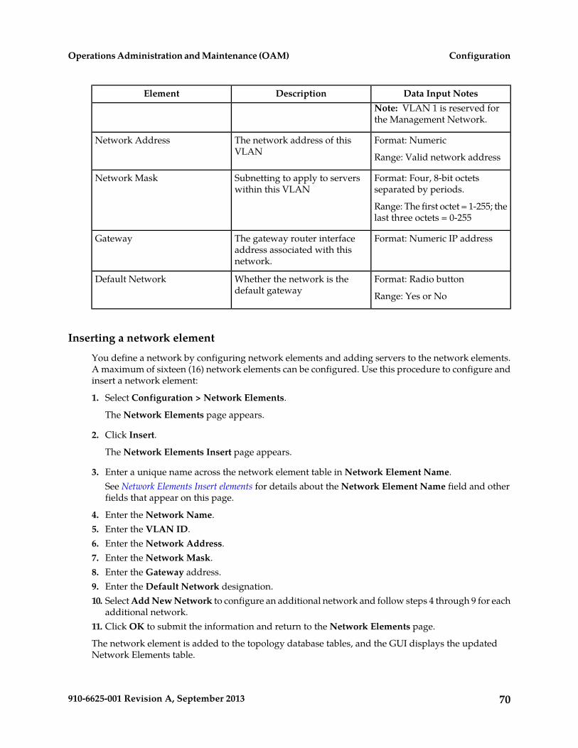
Data Input NotesDescriptionElementNote: VLAN 1 is reserved forthe Management Network.
Format: NumericThe network address of thisVLAN
Network Address
Range: Valid network address
Format: Four, 8-bit octetsseparated by periods.
Subnetting to apply to serverswithin this VLAN
Network Mask
Range: The first octet = 1-255; thelast three octets = 0-255
Format: Numeric IP addressThe gateway router interfaceaddress associated with thisnetwork.
Gateway
Format: Radio buttonWhether the network is thedefault gateway
Default Network
Range: Yes or No
Inserting a network element
You define a network by configuring network elements and adding servers to the network elements.A maximum of sixteen (16) network elements can be configured. Use this procedure to configure andinsert a network element:
1. Select Configuration > Network Elements.
The Network Elements page appears.
2. Click Insert.
The Network Elements Insert page appears.
3. Enter a unique name across the network element table in Network Element Name.See Network Elements Insert elements for details about the Network Element Name field and otherfields that appear on this page.
4. Enter the Network Name.5. Enter the VLAN ID.6. Enter the Network Address.7. Enter the Network Mask.8. Enter the Gateway address.9. Enter the Default Network designation.10. Select Add New Network to configure an additional network and follow steps 4 through 9 for each
additional network.11. Click OK to submit the information and return to the Network Elements page.
The network element is added to the topology database tables, and the GUI displays the updatedNetwork Elements table.
70910-6625-001 Revision A, September 2013
ConfigurationOperations Administration and Maintenance (OAM)

Uploading a configuration file
Use this procedure to upload an XML file to configure a new network element:
1. Select Configuration > Network Elements.
The Network Elements page appears.
2. Click Choose File to locate the file you want to use to configure a new network element.
The File Upload window appears.
3. Select the file you want to use to configure a new network element.The selected file appears in the text box.
4. Click Upload File.
Data validation is performed immediately. If the file is valid, a new network element is created.Alternately, a file that contains invalid parameters returns an error message, and no network elementis created.
Viewing Network Elements
Use this procedure to view network elements:
1. Select Configuration > Network Elements.The Network Elements Configuration page appears.
2. Click on the folder icon beside the Network Element Name to view additional information aboutthe selected network element.
Editing a Network Element
A network element can only be edited if no servers are associated with the network element.
Use this procedure to edit an existing network element:
1. Select Configuration > Network Elements.
The Network Elements page appears.
2. Click to select the unlocked network element and click Edit NE Networks.
The Network Elements Edit page appears.
3. Edit the available fields as necessary.4. Click OK to submit the changes and return to the Network Elements page.
The network element is changed.
71910-6625-001 Revision A, September 2013
ConfigurationOperations Administration and Maintenance (OAM)

Deleting a Network Element
You can delete an unlocked network element from the Network Elements page. If a network elementis locked it cannot be deleted. Before a network element can be deleted the following conditions mustbe true:there must be no servers associated with the network element.
• No servers are associated with the network element (see Deleting a Server).• In the case of an OAMP network element, no signaling-type network elements exist.
Use this procedure to delete a network element:
1. Select Configuration > Network Elements.
The Network Elements page appears.
2. Click to select the network element you want to delete and click Delete.
A delete confirmation message appears.
3. Click OK to delete the network element from the database tables.The updated Network Elements Configuration page appears.
The network element is deleted from the topology databases.
Network Element Report Elements
The report is divided into three sections, and each section contains subsections. Any field for whichthere is no data will display the value "n/a".
Table 44: Layer-3 Network Element Report
SubsectionSection
Each network element is listed individually withrelated general information. For details aboutthese values, see Network Elements Insert elements.
Network Element Summary
• RSTP Enabled• Frame ID• Position• Demarcation Type• Commit State
Each network element is listed individually withinformation about network.
Network Report
• Network Name: Name for the network• VLAN ID: Three character numeric VLAN ID• Network ID: Numeric network ID• Netmask: Mask used to divide an IP address
into subnets and specify the networks availablehosts
• Gateway: IP address for Gateway server
72910-6625-001 Revision A, September 2013
ConfigurationOperations Administration and Maintenance (OAM)

SubsectionSection• Type: Network type• Default: Whether the network is the default
gateway
Each network element is listed individually withinformation about the related servers.
Server Report
• Hostname: name of server associated with thenetwork element
• XMI Address: XMI address for server• IMI Address: IMI address for server• RMM Address: n/a
Generating a Network Element Report
A network element report provides a summary of the network element configuration. This report canbe used to:
• View network element configurations• Compare network element configurations to system manager network configurations• Relate network elements to servers, VLANs, and systems• View a list of the locations the application occupies• View a list of the IP addresses in the application topology
This report can also be printed or saved to a file.
Use this procedure to generate a network element report:
1. Select Configuration > Network Elements.
The Network Elements page appears.
2. To generate a report for a single network element, click to select the network element and clickReport. To generate a report for all configured network elements, click Report.Alternately, you can select multiple rows and generate a report using those. To select multiplerows, press and hold Ctrl as you click to select specific rows.The Network Element Report is generated.
3. Click Print to print the report.4. Click Save to save the report to a file.
Exporting a network element
The network element export button generates an installation script file used for hardware configuration.Use this procedure to export the configuration parameters of a network element:
1. Select Configuration > Network Elements.
The Network Elements page appears.
2. Click to select a network element from the table.
73910-6625-001 Revision A, September 2013
ConfigurationOperations Administration and Maintenance (OAM)

3. Click Export.A CSV file is created.
Services
This application allows for flexible network deployment, with each installation being able to configurenetwork elements with one or more networks and map a specific service to those networks. Thisflexibility allows for individual configuration of network routes. The system only defines the defaultroute if the default network is defined for the network element.
Configuration of services must follow a specific chronology.
1. Configure the first NOAMP Network Element And Server.2. Use the Services screen to map networks to services.
Note: It is important that Services be configured after the insertion of the NOAMP NE and beforeconfiguring any servers.
3. Configure the first NOAMP server.4. Configure the NOAMP server group.5. Add the first NOAMP server to the group.6. Configure the second NOAMP server.7. Add the second NOAMP server to the group.8. Configure the SOAM NE.9. Configure the SOAM servers.10. Configure the SOAM server group.11. Add the SOAM servers to the group.12. Configure any MP servers.13. Add MP servers into server groups, as necessary.
Editing Service information
Services are set during installation of the system. However, you can edit network characteristics ofthe services. Use this procedure to edit existing service information:
1. Select Configuration > Services.
The Services page appears.
2. Click Edit.
The Services [Edit] page appears.
3. Select from the available choices to determine the Intra-NE Network.4. Select from the available choices to determine the Inter-NE Network.5. Select Apply to save the changes you have made and remain on this screen, or select OK to save
the changes and return to the Services page.
74910-6625-001 Revision A, September 2013
ConfigurationOperations Administration and Maintenance (OAM)

Generating a Service Report
A service report provides a summary of the service configuration. This report can also be printed orsaved to a file.
Use this procedure to generate a service report:
1. Select Configuration > Services.
The Services page appears.
2. Click Report.The Services Report is generated.
3. Click Print to print the report.4. Click Save to save the report to a file.5. Click Back to return to the Services page.
Resource Domains
The Resource Domains function allows you to assign servers to domains.
Add new resource domain elements
This table describes the elements for adding a resource domain element:
Table 45: Add New Resource Domain Elements
Data Input NotesDescriptionElement
Format: Alphanumeric (A-Z, a-z,0-9) and underscore (_)characters.
The name for the resourcedomain.
Resource Domain Name
Range: Maximum length is 32characters
Format: Pulldown listThe profile associated with theresource domain.
Resource Domain Profile
Range: None, Alexa1, Alexa2
Range for PDRA: Policy Binding,Policy DRA, Policy Session
Format: CheckboxThe server groups associatedwith the resource domain
Server Groups
Range: NO_MP, NO_SG,SO_MP, SO_SG
Range for PDRA Policy Binding:NO Server Group,Site1BindingPsbrMpSg,
75910-6625-001 Revision A, September 2013
ConfigurationOperations Administration and Maintenance (OAM)

Data Input NotesDescriptionElementSite1DsrMp1Sg, Site1DsrMp2Sg,Site1SessionPsbrMpSg,Site1SoServerGroup
Range for Policy DRA:BindingPsbr1MpSg,IpfeServerGroup,LabCSOAMSG2,LABDDSRMSG, LabDSOAMSG,NOAMP_SG, PDRASG,SOAM_SG, SessionPsbr1MpSg
Range for Policy Session: NOServer Group,Site1BindingPsbrMpSg,Site1DsrMp1Sg, Site1DsrMp2Sg,Site1SessionPsbrMpSg,Site1SoServerGroup
Inserting a Resource Domain
Use this procedure to insert a resource domain:
1. Select Configuration > Resource Domains.2. Click Insert at the bottom of the table.
The Resource Domains Insert page appears.
3. Enter a Resource Domain Name. This is a user-defined name for the domain. The domain namemust be unique.
4. Select a Resource Domain Profile.5. Select a Server Group.6. Click OK to submit the information and return to the Resource Domains Configuration page, or
click Apply to submit the information and continue entering additional data.
The resource domain is added to the network database.
Editing a Resource Domain
Use this procedure to edit resource domain information
1. Select Configuration > Resource Domains.2. Select the resource domain from the listing.3. Click Edit at the bottom of the table.
The Edit Resource Domains page appears.
4. Modify one or more of the resource domain information fields.5. Click OK to submit the information and return to the Resource Domains Configuration page, or
click Apply to submit the information and continue editing additional data.
76910-6625-001 Revision A, September 2013
ConfigurationOperations Administration and Maintenance (OAM)

The resource domain information is updated in the network database and the changes take effectimmediately.
Viewing Resource Domains
Use this procedure to view resource domains:
Select Configuration > Resource Domains.
The Resource Domains configuration page appears.
Deleting a Resource Domain
Use this procedure to delete a resource domain:
1. Select Configuration > Resource Domains.
The Resource Domains Configuration page appears.
2. Click to select the resource domain you want to delete.
Note: To prevent large service disruptions, you cannot delete a Resource Domain with a profiletype or Policy Binding or Policy Session, unless the Policy DRA feature is deactivated. However,resource domains with a profile type of Policy DRA can be deleted without deactivation of thePolicy DRA feature.
3. Click Delete.Click Yes to confirm.
The resource domain is deleted from the network database table.
Generating a Resource Domains Report
Use this procedure to generate a resource domains report:
1. Select Configuration > Resource Domains.2. Click to select the resource domain for which you want to create a report.
Note: If no certificate is selected, the report will contain data about all certificate. Alternately, youcan select multiple rows and generate a report using those. To select multiple rows, press and holdCtrl as you click to select specific rows.
3. Click Report.The resource domain group report appears.
4. Click Print to print the report, or click Save to save a text file of the report.
77910-6625-001 Revision A, September 2013
ConfigurationOperations Administration and Maintenance (OAM)

Servers
Servers are the processing units of the application. All network elements have a pair of OAM serverswhich share an external management virtual IP address. Servers perform various roles within theapplication. The roles are:
• Network OAMP (NOAMP) - The NOAMP is one active and one standby server running the NOAMPapplication and operating in a high availability global configuration. It also provides a GUI whichis used for configuration, user administration and the viewing of alarms and measurements.
• System OAM (SOAM) - The SOAM is the combination of an active and a standby application serverrunning the SOAM application and operating in a high availability configuration. SOAM alsoprovides a GUI used for local configuration and viewing alarms and measurements details specificto components located within the frame (SOAM, MP). The SOAM supports up to 8 MPs.
Note: SOAM is not an available role in systems that do not support SOAMs.
• MP - MPs are servers with the application installed and are configured for MP functionality.• Query Server (QS) - The Query Server is an independent application server containing replicated
application data. A Query Server is located in the same physical frame as each NOAMP component.
The role you define for a server affects the methods it uses to communicate with other servers in thenetwork. For more information about how each interface is used, refer to the Network InstallationGuide that came with the product.
Add new server configuration elements
This table describes the elements on the Adding a new server page:
Table 46: Add New Server Configuration Elements
Data Input NotesDescriptionElement
Format: Alphanumeric (A-Z, a-z,0-9) and hyphen (-) characters.
The defined name for the server.The name must be unique across
Host Name
Hostname must begin and endwith an alphanumeric character.
the server table. Alphanumeric(A-Z, a-z, 0-9) and hyphen (-)characters are allowed. The Range: Maximum length is 20
charactersHostname must begin and endwith an alphanumeric character.
Format: Pulldown listThe defined type for the networkelement The Role selected here
Role
Range: Network OAM&P,System OAM, MP, Query Serveraffects which of the following IP
Addresses and VLAN IDs areavailable to be configured. Note: System OAM is not an
available role in systems that donot support SOAMs.
Default = noneSystem ID for the NOAMP orSOAM server.
System ID
78910-6625-001 Revision A, September 2013
ConfigurationOperations Administration and Maintenance (OAM)

Data Input NotesDescriptionElementRange = A 64-character string.Valid value is any text string.
Format: Pulldown list ofcustomized options
The hardware profile of theserver
Hardware Profile
Format: Pulldown listThe network element must firstbe set up using the
Network Element Name
Range: A valid Network ElementConfiguration > NetworkElements page.
Format: Text stringOptional, user supplied field toidentify the location of theserver.
Location
Range: Maximum length is 15characters
Format: n/aThe list of available interfacesfrom the hardware profile.
Interfaces: Network
The IP Address of the serverinterface in each network in theNetwork Element.
The IP address of the networkInterfaces: IP Address
Format: numeric
Format: drop down listThe interface with which the IPaddress is associated. The list is
Interfaces: Interface
populated with the availableinterfaces from the hardwareprofile.
Typically, this list includes bondinterfaces (e.g., bond0 and/orbond1). One interface isdisplayed for each network inthe network element.
Format: checkboxThis checkbox allows the user todecide whether to create aVLAN interface.
Interfaces: VLAN
If the box is checked, a VLANinterface will automatically becreated. If the box is not checked,the IP address will be assigneddirectly to the interface selectedfrom the dropdown box.
Only one IP address can beassociated with a non-VLANinterface (e.g., bond1). Onecheckbox is displayed for eachinterface.
79910-6625-001 Revision A, September 2013
ConfigurationOperations Administration and Maintenance (OAM)

Data Input NotesDescriptionElement
Format: checkboxSelection of preferred NTPsources, multiple sources can bedesignated as preferred.
Interfaces: Prefer
Every NTP Server IP Addressfield has a corresponding"Prefer" checkbox.
Inserting a Server
Servers can be inserted only after a network element has been provisioned.
Use this procedure to insert a server:
1. Select Configuration > Servers.2. Click Insert at the bottom of the table.
The Adding a new server page appears.
3. Enter a Hostname. This is a user-defined name for the server. The server name must be uniqueacross the server table.For more information about Hostname, or any field on this page, see Add new server configurationelements .
4. Select a Role.5. Enter the System ID.6. Select a Hardware Profile.7. Select a Network Element Name.
Select from the network element names defined previously on the Network Element Configurationpage.
8. Enter the IP address for the appropriate network in the Interfaces grid9. Select the Interface in the Interfaces grid.10. Select the VLAN ID for the network in the Interfaces grid, if applicable.11. Select the Prefer checkbox for preferred sources.12. Enter a Location.13. Click OK to submit the information and return to the Servers Configuration page, or click Apply
to submit the information and continue entering additional data.
The server is added to the network databases.
Servers Configuration elements
The Servers Configuration page lists all servers that are provisioned. This table describes the elementsof the Servers Configuration page.
80910-6625-001 Revision A, September 2013
ConfigurationOperations Administration and Maintenance (OAM)

DescriptionElement
The defined name for the server. The name mustbe unique across the server table. Alphanumeric
Hostname
(A-Z, a-z, 0-9) and hyphen (-) characters areallowed. The Hostname must begin and end withan alphanumeric character.
The defined role for the network element. Typesare:
Role
• Network OAMP - A pair of serversimplementing OAMP functions for the entirenetwork. There is only one pair of NOAMPServers per network, and they comprise theNOAMP Network Element. There can be onlytwo servers of this type in the Servers table.
• System OAM - Pairs of servers implementinga centralized database and local OAMfunctions for each SO Network Elementdeployed. There can be only two servers ofthis type per signaling Network Element.
Note: System OAM is not an available role insystems that do not support SOAMs.
• MP - Each pair or cluster of serversimplementing message processing functions.Each cluster is assigned to a signaling NetworkElement controlled by a pair of SOAM Servers.
• Query Server - An independent applicationserver that contains a replicated version of thePDBI database. It accepts replicated subscriberdata from the NOAMP and stores it in acustomer accessible database.
The Role selected here affects which of thefollowing IP Addresses and VLAN IDs areavailable to be set up.
The system IDSystem ID
The server groups to which the server belongs.Server Group
The name of the network element that isassociated with each server. The network element
Network Element
must first be configured using the Configuration> Network Elements page before it can beassociated with a server.
The location of the server. This field is optional.Location
The Place that the server is assigned to.Place
81910-6625-001 Revision A, September 2013
ConfigurationOperations Administration and Maintenance (OAM)

DescriptionElement
IP interface accessible to the outside world. Setup when Role is Network OAMP or System OAM.
Note: System OAM is not an available role insystems that do not support SOAMs.
Details: XMI IP Address
The IP address of the internal managementinterface. Set up this IP address for all servers.
Details: IMI IP Address
The IP address for the RMM interface.Details: RMM IP Address
Viewing Servers
Use this procedure to view servers:
Select Configuration > Servers.
The Servers Configuration page appears.
Deleting a Server
Before a server can be deleted the following conditions must be true:
• The server is not part of a server group.• The server is not configured as a server pair.
Use this procedure to delete a server:
1. Select Configuration > Servers.
The Servers Configuration page appears.
2. Click to select the server you want to delete.3. Click Delete.
Click Yes to confirm.
The server is deleted from the network database table.
Exporting a server
The server export button generates an installation script file used for hardware configuration. Use thisprocedure to export a single server. For information about how to export multiple servers at once, seeExporting multiple servers.
1. Select Configuration > Servers.2. Click to select a server to export.3. Click Export.
The server data is exported to an SH file.
4. Click Info.
82910-6625-001 Revision A, September 2013
ConfigurationOperations Administration and Maintenance (OAM)

The Info box appears.
5. Click the download link to download the file.
Exporting multiple servers
The server export button generates an installation script file used for hardware configuration. Use thisprocedure to export more than one server.
1. Select Configuration > Servers.2. Press and hold Ctrl as you click to select multiple servers.3. Click Export.
Data for the selected servers is exported to individual SH files located on the Status and Manage> Files page.
4. Click Info.The Info box appears.
5. Click the Status and Manage > Files link.The Status and Manage > Files page appears. The SH files for the server data exported in thisprocedure is located on the Status and Manage > Files page.
Generating a Server Report
Use this procedure to generate a server report:
1. Select Configuration > Servers.2. Click to select the server for which you want to create a report.
Note: If no certificate is selected, the report will contain data about all certificate. Alternately, youcan select multiple rows and generate a report using those. To select multiple rows, press and holdCtrl as you click to select specific rows.
3. Click Report.The servers report appears.
4. Click Print to print the report, or click Save to save a text file of the report.
Server Groups
The Server Groups feature allows the user to assign a function and redundancy model, parentrelationships, and levels to a group of servers that share the same role, such as OAMP, SOAM, andMP servers. The Server Groups feature also enables users to create new groups, add servers to existinggroups, edit groups, delete servers and server groups, and generate reports that contain server groupdata.
Server Groups Insert elements
This table describes the elements of the Insert Server Groups page.
83910-6625-001 Revision A, September 2013
ConfigurationOperations Administration and Maintenance (OAM)

Data Input NotesDescriptionElement
Format: Alphanumericcharacters and underscore
A unique name used to label the servergroup.
Server Group Name
"_" are allowed. Aminimum of one alphabeticcharacter is required.
Note: Server Group Namemust not start with a digit.
Range: Maximum length is32 characters.
Format: Pulldown menu
Range: Levels A, B, or C
The level of the servers belonging to thisgroup.
Level
Format: Pulldown menu
Note: If the level of thegroup being inserted is A,
The parent server group that functions asthe replication parent of the selected servergroup
Parent
then the parent field is noteditable and NONE isdisplayed in the pulldownmenu.
Format: Pulldown menu
Range: Functions supportedby the system
The defined function for the server group.Function
Range = An integerbetween 1 and 8
Default = 1
Specify the number of TCP connectionsthat will be used by replication over anyWAN connection associated with thisServer Group.
WAN ReplicationConnection Count
Inserting a Server Group
Use this procedure to configure a server group:
1. Select Configuration > Server Groups.2. Click Insert.
The Insert Server Groups page appears.
3. Enter the Server Group Name.For more information about Server Group Name, or any of the fields on this page, see Server GroupsInsert elements.
4. Select a Level from the pulldown menu.5. Select a Parent from the pulldown menu.6. Select a Function from the pulldown menu.7. Enter a WAN Replication Connection Count.
84910-6625-001 Revision A, September 2013
ConfigurationOperations Administration and Maintenance (OAM)

8. Click OK to submit the information and return to the Server Groups page, or click Apply to submitthe information and continue adding additional data.
Server Groups configuration elements
The Server Groups Configuration screen lists all server groups. The following information is displayed.
DescriptionElement
A unique name used to label the servergroup. Alphanumeric characters and '_'
Server Group Name
are allowed. A minimum of onealphabetic character is required. Thename cannot start with a digit. Maximumlength is 32 characters.
The level of the servers belonging to thisgroup.
Level
The parent server group that functions asthe replication parent of the selectedserver group.
Parent
The defined function for the server group.Function
The number of TCP connections that willbe used by replication over any WAN
Connection Count
connection associated with this ServerGroup.
The list of servers in the server group.Servers
Server Groups Edit elements
The Edit Server Groups page allows you to edit existing server groups. This table describes theelements of the Edit Server Groups page.
Data Input NotesDescriptionElement
Format: Alphanumericcharacters and underscore "_"
A unique name used to label theserver group.
Server Group Name
are allowed. A minimum of onealphabetic character is required.Must begin with an alphabeticcharacter.
Range: Maximum length is 32characters.
This field cannot be edited.The level of the serversbelonging to this group.
Level
This field cannot be edited.The parent server group thatfunctions as the replication
Parent
85910-6625-001 Revision A, September 2013
ConfigurationOperations Administration and Maintenance (OAM)

Data Input NotesDescriptionElementparent of the selected servergroup.
This field cannot be edited.The defined function for theserver group.
Function
Range = An integer between 1and 8
The number of TCP connectionsthat will be used by replication
WAN Replication ConnectionCount
over any WAN connection Default = 1associated with this ServerGroup.
Format: Valid IP address, or fieldmay be left blank
IP Address of the NTP server tobe used for clock
NTP Server 1
synchronization. This field isoptional. Range: Dotted quad decimal
(IPv4) or colon hex (IPv6)
Note: NTP Server 1 is editableonly for Level A server groups.
Format: Valid IP address, or fieldmay be left blank
IP Address of the backup NTPserver. This field is optional.
NTP Server 2
Range: Dotted quad decimal(IPv4) or colon hex (IPv6)
Note: NTP Server 2 is editableonly for Level A server groups.
CheckboxWhen checked, the server isincluded in the server group.
SG Inclusion
CheckboxWhen checked, the server ismarked as a preferred spare.
Preferred HA Role
When marked as a preferredspare, the server only assumesan active or standby role if all theother servers in the server groupare unavailable.
Format: Valid IP addressA virtual IP address shared bythe servers in this group that
VIP Assignment: VIP Address
Range: Dotted quad decimal(IPv4) or colon hex (IPv6)have networking interfaces on
the same layer-2 network.
Editing a Server Group
Once a server group is created, certain values can be edited, and available servers can be added to ordeleted from the server group. Use this procedure to edit a server group:
1. Select Configuration > Server Groups.
86910-6625-001 Revision A, September 2013
ConfigurationOperations Administration and Maintenance (OAM)

2. From the table, click to select the server group you want to edit.3. Click Edit.
The Edit Server Groups page appears.4. Edit the values you want to change.
Fields that cannot be edited will be grayed out. For more information about these fields, or any ofthe fields in this procedure, see Server Groups Edit elements.
5. Click OK to submit the information and return to the Server Groups page, or click Apply to submitthe information and continue adding additional data.
Adding a server to a server groupOnce a server group is created, servers can be added. Use this procedure to add a server to a servergroup:
1. Select Configuration > Server Groups.2. From the table, click to select the server group you want to edit.3. Click Edit.
The Edit Server Groups page appears. The Edit Server Groups page displays the servers in thenetwork element that are possible candidates for inclusion in the server group.
4. To add a server to the server group, select the checkbox for SG Inclusion. When checked, the serverwill be included in the server group.
5. To mark the server as a preferred spare, select to the checkbox for Preferred HA Role. When markedas a preferred spare, the server will only assume active or standby role if all the other servers inthe server group are unavailable.
6. To add a virtual IP address, select Add in the VIP Assignment section and enter the virtual IPaddress.
7. Click OK to submit the information and return to the Server Groups page, or click Apply to submitthe information and continue adding additional data.
Deleting a server from a server groupUse this procedure to delete a server from a server group:
1. Select Configuration > Server Groups.2. From the table, click to select the server group you want to edit.3. Click Edit.
The Edit Server Groups page appears.4. To delete a server from the server group, select the checkbox for SG Inclusion. When checked, the
server will be included in the server group.5. Click OK to submit the information and return to the Server Groups page.
Assigning a VIP to a server groupTo add a new VIP address to a server group, at least one server must be assigned to the server group,and the first server in the group must be accessible by the NOAMP.Use this procedure to assign a VIPto a server group.
Note: This procedure is optional and is only supported if the redundancy modelsystem supports VIP.
87910-6625-001 Revision A, September 2013
ConfigurationOperations Administration and Maintenance (OAM)

1. Select Configuration > Server Groups.2. From the table, click to select the server group you want to edit.3. Click Edit.
The Edit Server Groups page appears.4. Click Add to add a new VIP address to the server group.
Note: Multiple VIP addresses can be added.
5. Insert the VIP address.6. Click OK to submit the information and return to the Server Groups page, or click Apply to submit
the information and continue adding additional data.
Removing a VIP from a server groupUse this procedure to remove a VIP address from a server group:
1. Select Configuration > Server Groups.2. From the table, click to select the server group you want to edit.3. Click Edit.
The Edit Server Groups page appears.4. Click to select the VIP you want to remove from the server group.5. Click Remove.
The VIP address is removed from the server group.
6. Click OK to submit the information and return to the Server Groups page, or click Apply to submitthe information and continue adding additional data.
Deleting a Server Group
Use this procedure to delete a server group.
Note: Only a server group with no existing servers in the group can be deleted. For information abouthow to delete a server from a server group, see Deleting a Server.
1. Select Configuration > Server Groups.2. Click to select the server group you want to delete from the table.3. Click Delete.
A delete confirmation message appears in a pop up window.
4. Click OK to delete the server group.If you click Cancel, the server group will not be deleted, and you will be returned to the ServerGroups page.
Server Group Report Elements
The report is divided into two sections and each section contains subsections.
88910-6625-001 Revision A, September 2013
ConfigurationOperations Administration and Maintenance (OAM)

Note: Fields with no data display "n/a" with the exception of Virtual IP Address(es) and NTP Server(s).Virtual IP Address(es) and NTP Servers(s) fields are optional. If no data exists for those fields, thenthe fields will not display in the report.
SubsectionSection
Each server group is listed individually withrelated general information. For details aboutthese values, see Server Groups Edit elements.
Server Groups Summary
• NE Name• Level• Parent• Function• NTP Server(s)• Virtual IP Address(es)
Each network element is listed individually withinformation about the related servers.
Hostname: name of server(s) associated with thenetwork element
Server Report
• Hostname: name of server(s) associated withthe network element
• XMI Address: XMI address for server• IMI Address: IMI address for server• XSI Address: XSI address for server
Generating a Server Group Report
Use this procedure to generate a server group report:
1. Select Configuration > Server Groups.2. Click to select the server group for which you want to create a report.
Note: If no certificate is selected, the report will contain data about all certificate. Alternately, youcan select multiple rows and generate a report using those. To select multiple rows, press and holdCtrl as you click to select specific rows.
3. Click Report.The server group report appears.
4. Click Print to print the report, or click Save to save a text file of the report.
Places
The Places feature allows you to build associations for groups of servers at a single geographic location.These places can then be grouped into place associations, which create relationships between one ormore place.
89910-6625-001 Revision A, September 2013
ConfigurationOperations Administration and Maintenance (OAM)

Places Insert elements
This table describes the elements of the Places Insert page.
Data Input NotesDescriptionElement
Format: Alphanumericcharacters and underscore
A unique name used to label the place.Place Name
"_" are allowed. Aminimum of one alphabeticcharacter is required.
Range: Maximum length is32 characters.
Format: Pulldown menu
Any place that has noservers assigned is eligibleto be a parent
The parent place group that functions asthe replication parent of the selected place
Parent
Format: Pulldown menu
Range: Site (default option)or defined by theapplication.
The place type.Place Type
Format: CheckboxList of the available servers in the NO orSO
Servers
Inserting a Place
Use this procedure to configure a place:
1. Select Configuration > Places.2. Click Insert.
The Insert Places page appears.
3. Enter the Place Name.For more information about Place Name, or any of the fields on this page, see Place Insert Elements.
4. Select a Parent from the pulldown menu.5. Select a Place Type from the pulldown menu.6. Select the available Servers from the checklist.7. Click OK to submit the information and return to the Places page, or click Apply to submit the
information and continue adding additional data.
Editing a Place
Use this procedure to edit place information
90910-6625-001 Revision A, September 2013
ConfigurationOperations Administration and Maintenance (OAM)

1. Select Configuration > Places.2. Select the place from the listing.3. Click Edit at the bottom of the table.
The Places Edit page appears.
4. Modify one or more of the place information fields.5. Click OK to submit the information and return to the Places page, or click Apply to submit the
information and continue editing additional data.
The place information is updated in the network database and the changes take effect immediately.
Deleting a Place
Use this procedure to delete a place.
1. Select Configuration > Places.2. Click to select the place you want to delete from the table.
Note: A Place cannot be deleted if it includes servers or is a Parent Place. Before deleting,disassociate any servers or remove Parent status.
3. Click Delete.A delete confirmation message appears in a pop up window.
4. Click OK to delete the place.If you click Cancel, the place will not be deleted, and you will be returned to the Places page.
Generating a Places Report
Use this procedure to generate a places report:
1. Select Configuration > Places.2. Click to select the place for which you want to create a report.
Note: If no certificate is selected, the report will contain data about all certificate. Alternately, youcan select multiple rows and generate a report using those. To select multiple rows, press and holdCtrl as you click to select specific rows.
3. Click Report.The place report appears.
4. Click Print to print the report, or click Save to save a text file of the report.
Place Associations
The Place Association function allows you to create relationships between places. Places are groupsof servers at a single geographic location.
91910-6625-001 Revision A, September 2013
ConfigurationOperations Administration and Maintenance (OAM)

Place Association Insert elements
This table describes the elements of the Place Association Insert page.
Data Input NotesDescriptionElement
Format: Alphanumericcharacters and underscore
A unique name used to label the placeassociation.
Place Association Name
"_" are allowed. Aminimum of one alphabeticcharacter is required.
Range: Maximum length is32 characters.
Format: Pulldown menu
Range: defined by theapplication
The type of place association.Place Association Type
Format: Checkbox
Range: list of places definedusing Places function
The places available to be grouped in thisassociation
Places
Inserting a Place Association
Use this procedure to configure a place association:
1. Select Configuration > Place Association.2. Click Insert.
The Insert Place Associations page appears.
3. Enter the Place Association Name.For more information about Place Association Name, or any of the fields on this page, see PlaceAssociation Elements.
4. Select a Place Association Type from the pulldown menu.5. Click OK to submit the information and return to the Place Associations page, or click Apply to
submit the information and continue adding additional data.
Editing a Place Associations
Use this procedure to edit place associations information
1. Select Configuration > Place Associations.2. Select the place association from the listing.3. Click Edit at the bottom of the table.
The Edit Place Associations page appears.
92910-6625-001 Revision A, September 2013
ConfigurationOperations Administration and Maintenance (OAM)

4. Modify one or more of the place associations information fields.5. Click OK to submit the information and return to the Place Associations Configuration page, or
click Apply to submit the information and continue editing additional data.
The place association information is updated in the network database and the changes take effectimmediately.
Deleting a Place Association
Use this procedure to delete a place association.
1. Select Configuration > Place Associations.2. Click to select the place association you want to delete from the table.
Note: You cannot delete a Place Association that includes grouped Places. Before deleting thePlace Association, disassociate the Places from the Place Association
3. Click Delete.A delete confirmation message appears in a pop up window.
4. Click OK to delete the place association.If you click Cancel, the place association will not be deleted, and you will be returned to the PlaceAssociation page.
Generating a Place Associations Report
Use this procedure to generate a place associations report:
1. Select Configuration > Place Associations.2. Click to select the place associations for which you want to create a report.3. Click Report.
The place associations report appears.4. Click Print to print the report, or click Save to save a text file of the report.
DSCP
The Differentiated Services Code Point (DSCP) pages allow the user to configure service point codes.Through the DSCP Configuration page, Interface and Port DSCP information can be inserted andsaved to the configuration.
Interface DSCP
The Interface Differentiated Services Code Point (DSCP) pages allow the user to configure serverinterfaces for service point codes. Through the Interface DSCP Configuration page, DSCP informationcan be inserted and saved to the configuration.
93910-6625-001 Revision A, September 2013
ConfigurationOperations Administration and Maintenance (OAM)

Interface DSCP Insert elementsThis table describes the elements of the Interface DSCP Insert page.
Table 47: Interface DSCP Insert Elements
Data Input NotesDescriptionField
Format: Drop down list
Range: valid serverinterfaces
The network interface nameInterface
Format: Numeric
Range: 0 to 63, inclusive
DSCP value for the associated network interfacesDSCP
Inserting an Interface DSCPUse the following procedure for inserting an interface DSCP.
1. Select Configuration > DSCP > Interface DSCPThe Interface DSCP page appears.
2. Select the tab for Entire Network, NO_NE or SO_NE1.3. Click the Insert button.
The Insert Interface DSCP page appears.4. Select the Interface from the drop down listing of available server interfaces.5. Enter a valid DSCP value. A valid value is an integer between 0 and 63, inclusive.6. Click OK to submit the information and return to the DSCP page, or click Apply to submit the
information and continue entering additional data.
The new DSCP is added.
Deleting an Interface DSCPUse the following procedure for deleting an interface DSCP.
1. Select Configuration > DSCP > Interface DSCPThe Interface DSCP page appears.
2. Select the DSCP configuration to be deleted.3. Click Delete.
A confirmation box appears.4. Click OK to delete the DSCP
The DSCP is deleted.
Generating an Interface DSCP ReportAn interface DSCP report provides a summary of the configuration of one or more DSCPs. Reportscan be printed or saved to a file.
1. Select Configuration > DSCP > Interface DSCP
94910-6625-001 Revision A, September 2013
ConfigurationOperations Administration and Maintenance (OAM)

The Interface DSCP page appears.2. Click Report to generate a report for all DSCPs.
The DSCP Report is generated.3. Click Print to print the report.4. Click Save to save the report to a file.
Port DSCP
The Port Differentiated Services Code Point (DSCP) pages allow the user to configure server ports forservice point codes. Through the Port DSCP Configuration page, DSCP information can be insertedand saved to the configuration.
Port DSCP Insert elementsThis table describes the elements of the Port DSCP Insert page.
Table 48: Port DSCP Insert Elements
Data Input NotesDescriptionField
Format: Numeric
Range: 1 to 65535,inclusive
A valid TCP or SCTP portPort
Format: Numeric
Range: 0 to 63, inclusive
DSCP value for the associated portDSCP
Inserting a Port DSCPUse the following procedure for inserting a Port DSCP.
1. Select Configuration > DSCP > Port DSCPThe Port DSCP page appears.
2. Select the tab for Entire Network, NO_NE or SO_NE1.3. Click the Insert button.
The Insert Port DSCP page appears.4. Enter a valid Port value. A valid value is an integer between 1 and 65535, inclusive.5. Enter a valid DSCP value. A valid value is an integer between 0 and 63, inclusive.6. Click OK to submit the information and return to the DSCP page, or click Apply to submit the
information and continue entering additional data.
The new DSCP is added.
Deleting a Port DSCPUse the following procedure for deleting a Port DSCP.
1. Select Configuration > DSCP > Port DSCP
95910-6625-001 Revision A, September 2013
ConfigurationOperations Administration and Maintenance (OAM)

The Port DSCP page appears.2. Select the DSCP configuration to be deleted.3. Click Delete.
A confirmation box appears.4. Click OK to delete the DSCP
The DSCP is deleted.
Generating a Port DSCP ReportA Port DSCP report provides a summary of the configuration of one or more DSCPs. Reports can beprinted or saved to a file.
1. Select Configuration > DSCP > Port DSCPThe Port DSCP page appears.
2. Click Report to generate a report for all DSCPs.The DSCP Report is generated.
3. Click Print to print the report.4. Click Save to save the report to a file.
Network
The Network pages allow the user to configure signaling networks, devices, and routes. Through theNetwork Configuration page, network IDs and subnets can be added to enable servers to communicatewith the signaling networks. Route configuration allows the user to define specific routes for signalingtraffic. Device configuration allows the user to configure additional interfaces on MP servers used insignaling networks.
Network Insert elements
This table describes the elements of the Network Insert page.
Table 49: Network Insert Elements
Data Input NotesDescriptionField
Format: Alphanumeric;must begin with a letter
Range: 31 charactermaximum
The name of the NetworkNetwork Name
Format: Numeric
Range: 5-4094
The VLAN ID of the NetworkVLAN ID
Note: VLAN IDs 1-4are reserved forManagement, XMI, and
96910-6625-001 Revision A, September 2013
ConfigurationOperations Administration and Maintenance (OAM)

Data Input NotesDescriptionFieldIMI. VLAN IDs that arealready in use cannot bereused.
Format: Valid networkaddress
Range: Dotted decimal(IPv4) or colon hex(IPv6)
The network address of the NetworkNetwork Address
Range: Valid netmaskfor the network in prefix
Subnetting to apply to servers within the NetworkNetmask
length (IPv4 or IPv6) ordotted quad decimal(IPv4)
Inserting a Network
Use the following procedure for inserting a network. Alternatively, you can also use the proceduresincluded in the Network Elements topics.
1. Select Configuration > NetworkThe Network page appears.
2. Click the Insert button.The Network Insert page appears.
3. Enter a Network Name.For more information about Network Name, or any field on this page, see Network Insert elements.
4. Enter a VLAN ID.5. Enter a Network Address.6. Enter a Netmask.7. Click OK to submit the information and return to the Network page, or click Apply to submit the
information and continue entering additional data.
The new network is added.
Configuration Network elements
This table describes the elements of the Configuration Network page.
Table 50: Configuration Network Elements
DescriptionField
The name associated with the networkNetwork Name
VLAN ID associated with the networkVLAN
97910-6625-001 Revision A, September 2013
ConfigurationOperations Administration and Maintenance (OAM)

DescriptionField
The IP address associated with the network in the format: IPAddress/Prefix Length
Network
Editing a Network
Not all networks can be edited. Pre-configured networks created during the install process, for example,cannot be edited. A network that cannot be edited is distinguished using italic font.
Note: Prior to editing a network, generate a network report. The network report will serve as a recordof the network's original settings. Print or save the network report for your records. For moreinformation about generating a network report, see Generating a Network Report.
1. Select Configuration > NetworkThe Network page appears.
2. Click to select a network and click Edit.
Note: If the network cannot be edited, the Edit button will be disabled.
If the network can be edited, the Network Edit page appears.3. Edit the available fields as necessary.
See Network Insert elements for details about the fields that appear on this page.
Note: Fields that cannot be edited are disabled.
4. Click OK to submit the changes and return to the Network page, or click Apply to submit theinformation and continue editing additional data.
The network is changed.
Deleting a Network
Not all networks can be deleted. In-use networks and pre-configured networks created during theinstall process, for example, cannot be deleted. A network that cannot be deleted is distinguishedusing italic font.
Note: Prior to deleting a network, generate a network report. The network report will serve as a recordof the network's original settings. Print or save the network report for your records. For moreinformation about generating a network report, see Generating a Network Report.
1. Select Configuration > Network.The Network page appears.
2. Click to select the network you want to delete. Alternately, you can delete multiple networks. Todelete multiple networks, press and hold Ctrl and click to select specific networks.
Note: If the network cannot be deleted, the Delete button will be disabled.
Note: To delete multiple networks at one time, all selected networks must be deletable.
3. Click Delete.A confirmation box appears.
4. Click OK to delete the network.
98910-6625-001 Revision A, September 2013
ConfigurationOperations Administration and Maintenance (OAM)

The network is deleted.
Generating a Network Report
A network report provides a summary of the configuration of one or more networks. Reports can beprinted or saved to a file.
1. Select Configuration > NetworkThe Network page appears.
2. Click Report to generate a report for all networks. To generate a report for a single network, clickto select the network and click Report. Alternately, you can select multiple networks. To generatea report for multiple networks, press and hold Ctrl as you click to select specific networks.The Network Report is generated.
3. Click Print to print the report.4. Click Save to save the report to a file.
Devices
Device configuration allows the user to configure interfaces on MP servers used in signaling networks.
Device Insert elementsThis table describes the elements of the Devices Insert page.
Table 51: Devices General Options
Data Input NotesDescriptionField
Format: Radio button
Range: Ethernet,Bonding, VLAN, Alias
Note: Ethernet is notselectable.
The type of deviceDevice Type
Format: Pulldown list
Default: MII
The monitoring style to use with a bonding deviceDevice Monitoring
Range: MII, ARP
Note: DeviceMonitoring is disabledwhen the Device Typeis not Bonding.
Format: Checkbox
Default: Enabled
When selected, this checkbox enables the deviceto start on boot.
Start on Boot
99910-6625-001 Revision A, September 2013
ConfigurationOperations Administration and Maintenance (OAM)

Data Input NotesDescriptionField
Format: Pulldown list
Range: None, DHCP
The boot protocolBoot Protocol
Default: None
Format: Checkbox
Range: Available basedevices
The base device(s) for Bond, Alias, and VLANdevice types
Note: Alias and VLAN devices require oneselection; bond devices require two selections.
Base Device(s)
The MII Monitoring Options and ARP Monitoring Options tabs collect settings for MII and ARPmonitoring, respectively. The IP Interfaces tab allows interfaces to be associated with a device.
Table 52: Devices MII Monitoring Options tab
Data Input NotesDescriptionField
Format: Pulldown list
Range: None and availabledevices
The preferred primary interfacePrimary Interface
Default: None
Range: A positive integer
Default: 100ms
MII monitoring interval inmilliseconds
Monitoring Interval
Range: A positive integer
Default: 200ms
MII monitoring upstream delayin milliseconds
Upstream Delay
Range: A positive integer
Default: 200ms
MII monitoring downstreamdelay in milliseconds
Downstream Delay
Table 53: Devices ARP Monitoring Options tab
Data Input NotesDescriptionField
Format: Pulldown list
Range: Available devices
The preferred primary interfacePrimary Interface
Range: A positive integer
Default: 100ms
ARP monitoring interval inmilliseconds
Monitoring Interval
Format: Pulldown list
Range: None, Active, Backup,All
The method to validate the ARPprobes and replies
ARP Validation
Default: None
100910-6625-001 Revision A, September 2013
ConfigurationOperations Administration and Maintenance (OAM)

Data Input NotesDescriptionField
Format: Valid IP address
Range: Dotted quad decimal(IPv4) or colon hex (IPv6)
Comma-separated ARP target IPaddresses
ARP Target List
Table 54: Devices IP Interfaces tab
Data Input NotesDescriptionField
Format: Valid IP address
Range: Dotted quad decimal(IPv4) or colon hex (IPv6)
The IP address of the interfacesassociated with the device
IP Address List
Format: ButtonDisplays a textbox to add an IPAddress
Add Row
Note: Multiple rows can beadded.
Format: Textbox
Range: Dotted quad decimal(IPv4) or colon hex (IPv6)
Textbox for an IP addressIP Address textbox
Format: ButtonRemoves the device interface IPAddress on the selected row
Remove
Inserting a Device1. Select Configuration > Network > Devices.
The Devices page appears.2. Select a server.3. Click the Insert button.
The Device Insert page appears.4. Select a Device Type.
For more information about Device Type, or any field on this page, see Device Insert elements .
Note: Device Type of Ethernet cannot be selected.
5. Select a Device Monitoring style.
Note: Device Monitoring is only used when the Device Type is Bonding.
6. By default, Start on Boot is enabled. Uncheck the check box if you want to disable Start on Boot.7. Select the Boot Protocol.8. Select the Base Device(s) if the device type is one of the following: Bond, Alias, or VLAN.
Note: Alias and VLAN devices require one selection; bond devices require two selections.
9. Click OK to submit the information and return to the Device page, or click Apply to submit theinformation and continue entering additional data.
101910-6625-001 Revision A, September 2013
ConfigurationOperations Administration and Maintenance (OAM)

The device is added. You can now update MII and ARP monitoring options and add IP interfaces, ifapplicable.Inserting MII Monitoring OptionsInserting MII monitoring options is only required if the device type is Bonding. For all other devicetypes, the MII Monitoring Options tab is disabled.
1. Select Configuration > Network > Devices.The Devices page appears.
2. Select a server.3. Click the Insert button.
The Device Insert page appears.4. Click the MII Monitoring Options tab.
The MII Monitoring Options tab appears.5. Click Primary Interface to select None (for no interface) or the preferred interface from the pulldown
list.6. Enter the Monitoring Interval, if you do not wish to use the default setting.7. Enter the Upstream Delay, if you do not wish to use the default setting.8. Enter the Downstream Delay, if you do not wish to use the default setting.9. Click the General Options tab.10. Click OK to submit the information and return to the Device page, or click Apply to submit the
information and continue entering additional data.
The MII monitoring options are updated.Inserting ARP Monitoring OptionsInserting ARP monitoring options is only required if the device type is Bonding. For all other devicetypes, the ARP Monitoring Options tab is disabled.
1. Select Configuration > Network > Devices.The Devices page appears.
2. Select a server.3. Click the Insert button.
The Device Insert page appears.4. Click the ARP Monitoring Options tab.
The ARP Monitoring Options tab appears.5. Click Primary Interface to select None (for no interface) or the preferred interface from the pulldown
list.6. Enter the Monitoring Interval, if you do not wish to use the default setting.7. Click ARP Validation to select a validation method from the pulldown list, if you do not wish to
use the default setting.8. Enter one or more IP addresses for the target device.
Note: Multiple IP addresses are comma separated.
9. Enter an IP Address for the device.10. Click OK to submit the information and return to the Device page, or click Apply to submit the
information and continue entering additional data.
The ARP monitoring options are updated.
102910-6625-001 Revision A, September 2013
ConfigurationOperations Administration and Maintenance (OAM)

Inserting IP InterfacesThe IP interfaces tab allows interfaces to be associated with a device.
1. Select Configuration > Network > Devices.The Devices page appears.
2. Select a server.3. Click the Insert button.
The Device Insert page appears.4. Click the IP Interfaces tab.
The IP Interfaces tab appears.5. Click Add Row.
A textbox appears in which you can enter an IP Address for the device.6. Enter an IP Address for the device.7. Select a Network Name.8. For each row, only one IP Address and Network Name can be specified. To specify additional
rows, select Add Row and following Steps 6 and 7.9. When you are finished adding IP Addresses, click OK to submit the information and return to the
Device page, or click Apply to submit the information and continue entering additional data.
The IP addresses are added.
Devices elementsThis table describes the elements of the Configuration Devices page.
Table 55: Devices Elements
DescriptionField
The server host name displayed in tabbed format at the top of thetable
Server
The name of the deviceDevice Name
The device type. Supported types include:Device Type
• Bonding• VLAN• Alias• Ethernet
A collection of keyword value pairs for the device optionsDevice Options
IP address and network name in the format: IP Address (networkname)
IP Interface (Network)
The configuration status of the device. The possible states are:Configuration Status
• Discovered (provisioned directly on the server)• Configured (provisioned through the GUI; server update is
complete)• Pending (update in progress)
103910-6625-001 Revision A, September 2013
ConfigurationOperations Administration and Maintenance (OAM)

DescriptionField• Deferred (server cannot be reached for updates)• Error (specific error text is displayed in the Configuration Status
field)
Editing a DeviceNot all devices can be edited. Pre-configured devices created during the install process, for example,cannot be edited. A device that cannot be edited is distinguished using italic font.
Note: Prior to editing a device, generate a device report. The device report will serve as a record ofthe device's original settings. Print or save the device report for your records. For more informationabout generating a device report, see Generating a Device Report.
1. Select Configuration > Network > DevicesThe Devices page appears.
2. Click to select a server.The device data for the selected server appears.
3. Click to select a device and click Edit.
Note: If the device cannot be edited, the Edit button will be disabled.
If the device can be edited, the Device Edit page appears.4. Edit the available fields as necessary.
See Device Insert elements for details about the fields that appear on this page.
Note: Fields that cannot be edited are disabled.
5. Click OK to submit the changes and return to the Devices page, or click Apply to submit theinformation and continue editing additional data.
The device is changed.
Deleting a DeviceNot all devices can be deleted. In-use devices and pre-configured devices created during the installprocess, for example, cannot be deleted. A device that cannot be deleted is distinguished using italicfont.
Note: Prior to deleting a device, generate a device report. The device report will serve as a record ofthe device's original settings. Print or save the device report for your records. For more informationabout generating a device report, see Generating a Device Report.
1. Select Configuration > Network > Devices.The Devices page appears.
2. Click to select a server.The device data for the selected server appears.
3. Click to select the device you want to delete. Alternately, you can delete multiple devices. To deletemultiple devices, press and hold Ctrl and click to select specific devices.
Note: If the device cannot be deleted, the Delete button will be disabled.
Note: To delete multiple devices at one time, all selected devices must be deletable.
104910-6625-001 Revision A, September 2013
ConfigurationOperations Administration and Maintenance (OAM)

4. Click Delete.A confirmation box appears.
5. Click OK.The device is deleted.
Generating a Device Report1. Select Configuration > Network > Devices
The Devices page appears.2. Click to select a server.
The device data for the selected server appears.3. To generate a report for all devices, click Report. To generate a report for a single device, click to
select the device and click Report. Alternately, you can select multiple devices. To generate a reportfor multiple devices, press and hold Ctrl as you click to select specific devices.The Device Report is generated.
4. Click Print to print the report.5. Click Save to save the report to a file.
Routes
Use the Route Configuration page to define specific routes for signaling traffic. You can specify routesfor the entire network, specific servers, or specific server groups.
Routes Insert elementsThis table describes the elements of the Routes Insert page. Elements are displayed for the selectedserver or server group.
Table 56: Routes Insert Elements
Data Input NotesDescriptionField
Format: Radio button
Range: Default, Net,Host
The type of routeRoute Type
Note: The Default routeoption is available onlyif there is no defaultroute configured on thetarget server. There canbe no more than oneIPv4 and one IPv6default route defined.
105910-6625-001 Revision A, September 2013
ConfigurationOperations Administration and Maintenance (OAM)

Data Input NotesDescriptionField
Format: Pulldown list
Range: Provisioneddevices on the selectedserver
The network device name through which trafficis routed
Device
Format: Valid networkaddress
Range: Dotted quaddecimal (IPv4) or colonhex (IPv6)
The destination network address
Note: This field is disabled if the Route Type isdefault.
Destination
Format: Valid netmask
Range: Valid netmaskfor the network in prefix
A valid netmask for the destination network
Note: This field is disabled if the Route Type isdefault. This field is disabled and set to 32 (IPv4)or 128 (IPv6) if the Route Type is host.
Netmask
length (IPv4 or IPv6) ordotted quad decimal(IPv4)
Default: 24 for IPv4; 64for IPv6
Format: Valid IPaddress
Range: Dotted quaddecimal (IPv4) or colonhex (IPv6)
The IP Address of the gateway for the routeGateway IP
Inserting a Route1. Select Configuration > Network > Routes
The Routes page appears.2. Using the tabs, select to add a server or server group to the entire network, or a specific network
group.3. Click the Insert button.
The Routes Insert page appears.4. Select a Route Type.
For more information about Route Type, or any field on this page, see Routes Insert elements .
5. Select a Device.6. Enter a Destination.
Note: This step is required only if the Route Type is Net or Host. The field is disabled if the RouteType is Default.
7. Enter the Netmask.
Note: This step is required only if the Route Type is Net. The field is disabled if the Route Typeis Default or Host.
106910-6625-001 Revision A, September 2013
ConfigurationOperations Administration and Maintenance (OAM)

8. Enter the Gateway IP.9. Click OK to submit the information and return to the Route page, or click Apply to submit the
information and continue entering additional data.
The route is added.
Routes elementsThis table describes the elements of the Configuration Routes page.
Table 57: Routes Elements
DescriptionField
The server host name and server groups are displayed in tabbedformat at the top of the table
Server/Server Group
The type of routeRoute Type
The destination network IP address and prefix length in the format:IP Address/Prefix Length
Destination
A valid netmask for the destination networkNetmask
The IP Address of the gateway for the routeGateway
The device associated with the route for the gatewayDevice Name
The configuration status of the route. The possible states are:Configuration Status
• Discovered (provisioned directly on the server)• Configured (provisioned through the GUI; server update is
complete)• Pending (update in progress)• Deferred (server cannot be reached for updates)• Error (specific error text is displayed in the Configuration Status
field)
Editing a RouteNot all routes can be edited. Pre-configured routes created during the install process, for example,cannot be edited. A route that cannot be edited is distinguished using italic font.
Note: Prior to editing a route, generate a route report. The route report will serve as a record of theroute's original settings. Print or save the route report for your records. For more information aboutgenerating a route report, see Generating a Route Report.
1. Select Configuration > Network > Routes.The Routes page appears.
2. Click to select a server or server group using the tabs at the top of the table.The route data for the selected server or server group appears.
3. Click to select a route and click Edit.
Note: If the route cannot be edited, the Edit button will be disabled.
107910-6625-001 Revision A, September 2013
ConfigurationOperations Administration and Maintenance (OAM)

If the route can be edited, the Routes Edit page appears.4. Edit the available fields as necessary.
See Routes Insert elements for details about the fields that appear on this page.
Note: Fields that cannot be edited are disabled.
5. Click OK to submit the changes and return to the Routes page, or click Apply to submit theinformation and continue editing additional data.
The route is changed.
Deleting a RouteNot all routes can be deleted. In-use routes and pre-configured routes created during the install process,for example, cannot be deleted. A route that cannot be deleted is distinguished using italic font.
Note: Prior to deleting a route, generate a route report. The route report will serve as a record of theroute's original settings. Print or save the route report for your records. For more information aboutgenerating a route report, see Generating a Route Report.
1. Select Configuration > Network > Routes.The Routes page appears.
2. Click to select a server or server group from the tabs at the top of the table.The route data for the selected server or server group appears.
3. Click to select the route you want to delete. Alternately, you can delete multiple routes. To deletemultiple routes, press and hold Ctrl and click to select specific routes.
Note: If the route cannot be deleted, the Delete button will be disabled.
Note: To delete multiple routes at one time, all selected routes must be deletable.
4. Click Delete.A confirmation box appears.
5. Click OK to delete the routeThe route is deleted.
Generating a Route Report1. Select Configuration > Network > Routes
The Routes page appears.2. Click to select a server or server group from the tabs at the top of the table.3. Click Report to generate a report for all routes. To generate a report for a single route, click to select
the route and click Report. Alternately, you can select multiple routes. To generate a report formultiple routes, press and hold Ctrl as you click to select specific routes.The Route Report is generated.
4. Click Print to print the report.5. Click Save to save the report to a file.
108910-6625-001 Revision A, September 2013
ConfigurationOperations Administration and Maintenance (OAM)

Chapter
4Alarms and Events
This section provides an overview of alarms andevents. Application alarms and events are
Topics:
• Alarms and events defined.....110 unsolicited messages used in the system for trouble• Alarm and event ID ranges .....112 notification and to communicate the status of the
system to Operations Services (OS). The application• Alarm and event types.....112merges unsolicited alarm messages and unsolicited• Active alarms elements .....114informational messages from all servers in a• Viewing active alarms.....115 network and notifies you of their occurrence. Alarms
• Active alarms data export elements .....115 enable a network manager to detect faults early and• Exporting active alarms.....116 take corrective action to prevent a degradation in
the quality of service.• Generating a report of active alarms.....117• Historical alarms and events elements .....118 Since alarms from each server are merged into one
table of alarms at the SOAM and NOAMP servers,• Viewing alarm and event history.....119alarms should be viewed at the SOAM or NOAMP• Historical events data export elements .....119servers. When you log in to the GUI at the SOAM• Exporting alarm and event history.....120server, only alarms within that Network Element• Generating a report of historical alarms and
events.....121 are visible. However, if you log in to the GUI at theNOAMP server, all alarms in the entire system arevisible.• View Trap Log.....122
• View Trap Log elements .....122The Alarms and Events menu also features a pagefor viewing and generating reports of SNMP traps.• Viewing trap logs.....123
• View Trap Log Report elements.....124• Generating a trap log report.....125
109910-6625-001 Revision A, September 2013

Alarms and events defined
Alarms provide information pertaining to a system's operational condition that a network managermay need to act upon. An alarm might represent a change in an external condition, for example, acommunications link has changed from connected to a disconnected state. Alarms can have theseseverities:
• Critical• Major• Minor• Cleared - An alarm is considered inactive once it has been cleared, and cleared alarms are logged
on the Alarms & Events > View History page.
Events note the occurrence of an expected condition, such as an unsuccessful login attempt by a user.Events have a severity of Info and are logged on the View History page.
The following figure shows how alarms and events are organized in the application.
Figure 3: Flow of Alarms
110910-6625-001 Revision A, September 2013
Alarms and EventsOperations Administration and Maintenance (OAM)

Figure 4: Flow of Alarms
Alarms and events are recorded in a database log table. Application event logging provides an efficientway to record event instance information in a manageable form, and is used to:
• Record events that represent alarmed conditions• Record events for later browsing• Implement an event interface for generating SNMP traps
Alarm indicators, located in the User Interface banner, indicate all critical, major, and minor activealarms. A number and an alarm indicator combined represent the number of active alarms at a specificlevel of severity. For example, if you see the number six in the orange-colored alarm indicator, thatmeans there are six major active alarms.
Figure 5: Alarm Indicators Legend
Figure 6: Trap Count Indicator Legend
111910-6625-001 Revision A, September 2013
Alarms and EventsOperations Administration and Maintenance (OAM)

Alarm and event ID ranges
The AlarmID listed for each alarm falls into one of the following process classifications:
Table 58: Alarm/Event ID Ranges
Alarm ID RangeApplication/Process Name
5000-5099IPFE
10000-10999OAM
12000-12999SBR
19800-19909ComAgent
19910-19999DSR Diagnostics
22000-22999DSR
24400-24499TVOE
25000-25499CAPM
25500-25899OAM Alarm Management
31000-32700Platform
Alarm and event types
This table describes the possible alarm/event types that can be displayed.
Note: Not all Tekelec applications use all of the alarm types listed.
Table 59: Alarm and Event Types
TypeType Name
Communication Agent (ComAgent)CAF
Computer-Aided Policy Making (DiameterMediation)
CAPM
ConfigurationCFG
ChargingCHG
Congestion ControlCNG
CollectionCOLL
Charging Proxy ApplicationCPA
Diameter Application Server (Message Copy)DAS
112910-6625-001 Revision A, September 2013
Alarms and EventsOperations Administration and Maintenance (OAM)

TypeType Name
DatabaseDB
DiameterDIAM
DiskDISK
Domain Name ServiceDNS
Data Processor ServerDPS
Event Responder ApplicationERA
Full Address Based ResolutionFABR
High AvailabilityHA
Home Subscriber ServerHSS
InterfaceIF
Internet ProtocolIP
IP Front EndIPFE
LoggingLOG
MeasurementsMEAS
MemoryMEM
Number PortabilityNP
Operations, Administration & MaintenanceOAM
Policy DRAPDRA
Policy SBRpSBR
PlatformPLAT
ProcessPROC
ProvisioningPROV
Network Address TranslationNAT
Range-Based Address ResolutionRBAR
ReplicationREPL
Stream Control Transmission ProtocolSCTP
Subscriber Database ServerSDS
Signaling CompressionSIGC
Session Initiation Protocol InterfaceSIP
Selective LoggingSL
Signaling System 7SS7
113910-6625-001 Revision A, September 2013
Alarms and EventsOperations Administration and Maintenance (OAM)

TypeType Name
SIP Signaling RouterSSR
EXG StackSTK
Software (generic event type)SW
Transmission Control ProtocolTCP
Active alarms elements
This table describes the elements on the View Active alarms page.
Table 60: Active Alarms Elements
DescriptionActive Alarms Element
A system-wide unique number assigned to eachalarm
Sequence #
A unique number assigned to each alarm in thesystem. See Alarm and event ID ranges for moreinformation.
Alarm ID
Description of the alarm. The description istruncated to 140 characters.
Note: The Alarm Text field is not truncated inexports or reports.
Alarm Text
Date and time the alarm occurred (fractionalseconds resolution)
Timestamp
Alarm severity - Critical, Major, MinorSeverity
Name of the product or application that generatedthe alarm
Product
Name of the process that generated the alarmProcess
Name of the Network Element where the alarmoccurred
NE
Name of the server where the alarm occurredServer
Alarm or Event Type, e.g. Process, Disk, Platform.See Alarm and event types for more information.
Type
Instance of the alarm, e.g. Link01 or Disk02. TheInstance provides additional information to help
Instance
differentiate two or more alarms with the samenumber. This field may be blank if differentiationis not necessary
114910-6625-001 Revision A, September 2013
Alarms and EventsOperations Administration and Maintenance (OAM)

Viewing active alarms
Active alarms are displayed in a scrollable, optionally filterable table. By default, the active alarmsare sorted by time stamp with the most recent alarm at the top.
Use this procedure to view active alarms.
Note: The alarms and events that appear in View Active vary depending on whether you are loggedin to an NOAMP or SOAM. Alarm collection is handled solely by NOAMP servers in systems that donot support SOAMs.
1. Select Alarms & Events > View Active.The View Active page appears.
2. If necessary, specify filter criteria and click Go.The active alarms are displayed according to the specified criteria.
The active alarms table updates automatically. When new alarms are generated, the table isautomatically updated, and the view returns to the top row of the table.
3. To suspend automatic updates, click any row in the table.The following message appears: (Alarm updates are suspended.)
If a new alarm is generated while automatic updates are suspended, a new message appears:(Alarm updates are suspended. Available updates pending.)
To resume automatic updates, press and hold Ctrl as you click to deselect the selected row.
Active alarms data export elements
This table describes the elements on the View Active Export alarms page.
Table 61: Schedule Active Alarm Data Export Elements
Data Input NotesDescriptionElement
Format: TextboxName of the scheduled taskTask Name
Range: Maximum length is 40characters; alphanumeric (a-z,A-Z, and 0-9) and minus sign (-).Task Name must begin and endwith an alphanumeric character.
Format: TextboxDescription of the scheduled taskDescription
Range: Maximum length is 255characters; alphanumeric (a-z,A-Z, and 0-9) and minus sign (-).Description must begin with analphanumeric character.
115910-6625-001 Revision A, September 2013
Alarms and EventsOperations Administration and Maintenance (OAM)

Data Input NotesDescriptionElement
Format: Radio buttonFrequency at which the exportoccurs
Export Frequency
Range: Once, Fifteen Minutes,Hourly, Daily, or Weekly
Default: Once
Format: Scrolling listIf hourly is selected for UploadFrequency, this is the minute of
Minute
Range: 0 to 59each hour when the data will bewritten to the export directory. Default: 0
Format: Time textboxTime of day the export occursTime of Day
Range: 15-minute increments
Default: 12:00 AM
Format: Radio buttonDay of week on which the exportoccurs
Day of Week
Range: Sunday, Monday,Tuesday, Wednesday, Thursday,Friday, or Saturday
Default: Sunday
Exporting active alarms
You can schedule periodic exports of alarm data from the Alarms and Events View Active page.Active alarm data can be exported immediately, or you can schedule exports to occur daily or weekly.If filtering has been applied in the View Active page, only filtered data is exported.
During data export, the system automatically creates a CSV file of the filtered data. The file will beavailable in the file management area until you manually delete it, or until the file is transfered to analternate location using the Export Server feature. For more information about using Export Server,see Data Export.
Alarm details can be exported to a file by clicking the Export button on the View Active page. Thesystem automatically creates and writes the exported active alarm details to a CSV file in the filemanagement area.
If filtering has been applied in the View Active page, only filtered, active alarms are exported.
Use this procedure to export active alarms to a file.Use this procedure to schedule a data export task.
1. Select Alarms & Events > View Active.The View Active page appears.
2. If necessary, specify filter criteria and click Go.The active alarms are displayed according to the specified criteria.
3. Click Export.The Schedule Active Alarm Data Export page appears.
116910-6625-001 Revision A, September 2013
Alarms and EventsOperations Administration and Maintenance (OAM)

4. Enter the Task Name.For more information about Task Name, or any field on this page, see Active alarms data exportelements .
5. Select the Export Frequency.6. Select the Time of Day.
Note: Time of Day is not an option if Export Frequency equals Once.
7. Select the Day of Week.
Note: Day of Week is not an option if Export Frequency equals Once.
8. Click OK or Apply to initiate the active alarms export task.
From the Status & Manage > Files page, you can view a list of files available for download, includingthe file you exported during this procedure. For more information, see Displaying the file list.
Scheduled tasks can be viewed, edited, and deleted, and reports of scheduled tasks can be generatedfrom Status & Manage > Tasks. For more information see:
• Viewing scheduled tasks• Editing a scheduled task• Deleting a scheduled task• Generating a scheduled task report
9. Click Export.The file is exported.
10. Click the link in the green message box to go directly to the Status & Manage > Files page.
From the Status & Manage > Files page, you can view a list of files available for download, includingthe active alarms file you exported during this procedure.
Generating a report of active alarms
Use this procedure to generate a report.
1. Select Alarms & Events > View Active.
The View Active page appears.
2. Specify filter criteria, if necessary, and click Go.The active alarms are displayed according to the specified criteria. Alternately, you can selectmultiple rows and generate a report using those. To select multiple rows, press and hold Ctrl asyou click to select specific rows.
3. Click Report.The View Active Report is generated. This report can be printed or saved to a file.
4. Click Print to print the report.5. Click Save to save the report to a file.
117910-6625-001 Revision A, September 2013
Alarms and EventsOperations Administration and Maintenance (OAM)

Historical alarms and events elements
This table describes the elements on the View History alarms and events page.
Table 62: Historical Alarms Elements
DescriptionHistorical Alarms Element
A system-wide unique number assigned to eachalarm/event.
Sequence #
A unique number assigned to each alarm/eventin the system.
Event ID
Description of the alarm/event. The descriptionis truncated to 140 characters. If the description
Event Text
is truncated, a link to the alarm report will beappended.
Date and time the alarm/event occurred(fractional seconds resolution).
Timestamp
Alarm/event severity - Critical, Major, Minor andInfo.
Severity
Any additional information about the alarm/eventthat might help fix the root cause of the
Additional Info
alarm/event. Additional Information is truncatedto 140 characters.
Note: Additional Info field is not truncated inexports or reports.
Name of the product or application that generatedthe alarm/event.
Product
Name of the process that generated thealarm/event.
Process
Name of the Network Element where thealarm/event occurred.
NE
Name of the server where the alarm/eventoccurred.
Server
Alarm or Event Type, e.g. Process, Disk, Platform.See Alarm and event types for more information.
Type
Instance of the alarm/event, e.g. Link01 or Disk02.The Instance provides additional information to
Instance
help differentiate two or more alarms/events withthe same number. This field may be blank ifdifferentiation is not necessary.
118910-6625-001 Revision A, September 2013
Alarms and EventsOperations Administration and Maintenance (OAM)

Viewing alarm and event history
All historical alarms and events are displayed in a scrollable, optionally filterable table. The historicalalarms and events are sorted, by default, by time stamp with the most recent one at the top. Use thisprocedure to view alarm and event history.
Note: The alarms and events that appear in View History vary depending on whether you are loggedin to an NOAMP or SOAM. Alarm collection is handled solely by NOAMP servers in systems that donot support SOAMs.
1. Select Alarms & Events > View History .The View History page appears.
2. If necessary, specify filter criteria and click Go.
Note: Some fields, such as Additional Info, truncate data to a limited number of characters. Whenthis happens, a More link appears. Click More to view a report that displays all relevant data.
Historical alarms and events are displayed according to the specified criteria.
The historical alarms table updates automatically. When new historial data is available, the tableis automatically updated, and the view returns to the top row of the table.
3. To suspend automatic updates, click any row in the table.The following message appears: (Alarm updates are suspended.)
If a new alarm is generated while automatic updates are suspended, a new message appears:(Alarm updates are suspended. Available updates pending.)
To resume automatic updates, press and hold Ctrl as you click to deselect the selected row.
Historical events data export elements
This table describes the elements on the View History Export page.
Table 63: Schedule Event Data Export Elements
Data Input NotesDescriptionElement
Format: TextboxName of the scheduled taskTask Name
Range: Maximum length is 40characters; alphanumeric (a-z,A-Z, and 0-9) and minus sign (-).Task Name must begin and endwith an alphanumeric character.
Format: TextboxDescription of the scheduled taskDescription
Range: Maximum length is 255characters; alphanumeric (a-z,A-Z, and 0-9) and minus sign (-).
119910-6625-001 Revision A, September 2013
Alarms and EventsOperations Administration and Maintenance (OAM)

Data Input NotesDescriptionElementDescription must begin with analphanumeric character.
Format: Radio buttonFrequency at which the exportoccurs
Export Frequency
Range: Fifteen Minutes, Hourly,Once, Weekly, or Daily
Default: Once
Format: Scrolling listIf hourly is selected for UploadFrequency, this is the minute of
Minute
Range: 0 to 59each hour when the data will bewritten to the export directory. Default: 0
Format: Time textboxTime of day the export occursTime of Day
Range: 15-minute increments
Default: 12:00 AM
Format: Radio buttonDay of week on which the exportoccurs
Day of Week
Range: Sunday, Monday,Tuesday, Wednesday, Thursday,Friday, or Saturday
Default: Sunday
Exporting alarm and event history
You can schedule periodic exports of historical data from the Alarms and Events View History page.Historical data can be exported immediately, or you can schedule exports to occur daily or weekly. Iffiltering has been applied in the View History page, only filtered data is exported.
During data export, the system automatically creates a CSV file of the filtered data. The file will beavailable in the file management area until you manually delete it, or until the file is transfered to analternate location using the Export Server feature. For more information about using Export Server,see Data Export.
The details of historical alarms and events can be exported to a file by clicking the Export button onthe View History page. The system automatically creates and writes the exported historical alarmdetails to a CSV file in the file management area.
If filtering has been applied in the View History page, only filtered historical alarms and events areexported. Use this procedure to export alarm and event history to a file. Use this procedure to schedulea data export task.
1. Select Alarms & Events > View History.The View History page appears.
2. If necessary, specify filter criteria and click Go.The historical alarms and events are displayed according to the specified criteria.
120910-6625-001 Revision A, September 2013
Alarms and EventsOperations Administration and Maintenance (OAM)

3. Click Export.The Schedule Event Data Export page appears.
4. Enter the Task Name.For more information about Task Name, or any field on this page, see Historical events data exportelements .
5. Select the Export Frequency.6. If you selected Hourly, specify the Minutes.7. Select the Time of Day.
Note: Time of Day is not an option if Export Frequency equals Once.
8. Select the Day of Week.
Note: Day of Week is not an option if Export Frequency equals Once.
9. Click OK or Apply to initiate the data export task.
The data export task is scheduled. From the Status & Manage > Files page, you can view a list offiles available for download, including the alarm history file you exported during this procedure.For more information, see Displaying the file list.
Scheduled tasks can be viewed, edited, and deleted, and reports of scheduled tasks can be generatedfrom Status & Manage > Tasks. For more information see:
• Viewing scheduled tasks• Editing a scheduled task• Deleting a scheduled task• Generating a scheduled task report
10. Click Export.The file is exported.
11. Click the link in the green message box to go directly to the Status & Manage > Files page.
From the Status & Manage > Files page, you can view a list of files available for download, includingthe alarm history file you exported during this procedure. For more information, see .
Generating a report of historical alarms and events
Use this procedure to generate a report.
1. Select Alarms & Events > View History.
The View History page appears.
2. Specify filter criteria, if necessary, and click Go.The historical alarms and events are displayed according to the specified criteria.
3. Click Report.The View History Report is generated. This report can be printed or saved to a file.
121910-6625-001 Revision A, September 2013
Alarms and EventsOperations Administration and Maintenance (OAM)

4. Click Print to print the report.5. Click Save to save the report to a file.
View Trap Log
The View Trap Log page allows you to monitor traps from external application equipment, such asswitches and enclosures. The purpose of monitoring traps is to gain early warning of possible serviceimpacting conditions. View Trap Log provides a visual indicator of active, existing conditions. It alsoprovides a detailed log recording the historical conditions present in the external monitored hardwareand important background information for investigating the root cause of the condition.
View Trap Log elements
This table describes the elements on the View Trap Log page.
Table 64: View Trap Log Elements
DescriptionElement
The timestamp (in UTC) when the trap recordwas collected on the current system.
Timestamp
The Object Identifier (OID) for the trap.OID
The uptime as reported by the monitored externalequipment.
upTime
The name of the server that first logged the trap.Trap Collector
The external hostname (or IP, if name cannot beresolved) for the trap source.
Trap Source
The OID/value pairs found in the varbind list.
Note: Only the first few OID/value pairs will bedisplayed. A link to the report for the record willbe added if the varbind list is truncated.
VarBinds
When the Acknowledge All button is clicked, upto 2000 traps selected by the filter are cleared.
Acknowledge All
Acknowledge Acknowledged traps are removed from both thetrap count indicator and the View Trap Log page.
Note: Acknowledge All is the default setting forthis button. When one or more traps are selected,the button toggles to Acknowledge, and only theselected traps are affected.
122910-6625-001 Revision A, September 2013
Alarms and EventsOperations Administration and Maintenance (OAM)

DescriptionElement
When the Unacknowledge All button is clicked,all previously acknowledged traps selected by the
Unacknowledge All
Unacknowledge filter reappear on the page. Unacknowledgedtraps are added to the trap count indicator.
Note: Unacknowledge All is the default settingfor this button. When one or more traps areselected, the button toggles to Unacknowledge,and only the selected traps are affected.
When the Report All button is clicked, a reportis generated that contains information about thefirst 25 traps selected by the filter.
Note: Report All is the default setting for thisbutton. When one or more traps are selected, the
Report All
Report
button toggles to Report, and only the selectedtraps are included in the report.
Selection of this checkbox shows (if checked) orhides (if unchecked) the acknowledged traprecords.
Note: This checkbox is a filter option that is onlyavailable on the View Trap Log page.
Show: Ack'ed
Viewing trap logs
Trap logs are displayed in a scrollable, optionally filterable table.
1. Select Alarms & Events > View Trap Log.The View Trap Log page appears.
2. If necessary, specify filter criteria and click Go.3. If necessary, click to select any traps you want to acknowledge.
Note: Acknowledging a trap will cause the trap to be removed from the table and from the trapcount indicator. For more information, see View Trap Log elements .
Alternately, click Acknowledge All to acknowledge all traps, or click Unacknowledge All to showall traps in the table once again.
The trap log table updates automatically. When new traps are available, the table is automaticallyupdated, and the view returns to the top row of the table.
4. To suspend automatic updates, click any row in the table.The following message appears: (SNMP Trap updates are suspended.)
If a new trap is generated while automatic updates are suspended, a new message appears: (SNMPTrap updates are suspended. Available updates pending.)
To resume automatic updates, press and hold Ctrl as you click to deselect the selected row.
123910-6625-001 Revision A, September 2013
Alarms and EventsOperations Administration and Maintenance (OAM)

View Trap Log Report elements
This table describes the elements on the View Trap Log Report page.
Table 65: View Trap Log Report Elements
DescriptionElement
Indicates whether the trap has beenacknowledged.
Value = True or False
acked
Indicates whether the trap has been marked as aduplicate.
Value = True or False
duplicate
The trap ID is an internal sequence number toidentify specific traps from the same source.
trapId
The Object Identifier (OID) for the trap.OID
The upTime as reported by the monitored externalequipment.
upTime
The name of the server that first logged the trap.srcNode
The Network Element of the server that firstlogged the trap.
networkElement
The timestamp (in UTC) when the trap recordwas collected on the current system.
Note: This is the timestamp used when specifyingthe collection interval.
timeStamp
The time (in UTC) when the specific trap recordwas received at the system that first logged thetrap.
srcTimeStamp
The external hostname (or IP, if name cannot beresolved) for the trap source.
Trap Source
The IP address of the external hardware beingmonitored.
trapSourceIP
The specific OID/value pairs found in the varbindlist. There will be a varbind entry for each varbindin the logged trap record.
varbind
124910-6625-001 Revision A, September 2013
Alarms and EventsOperations Administration and Maintenance (OAM)

Generating a trap log report
Use this procedure to generate a report..
1. Select Alarms & Events > View Trap Log.The View Trap Log page appears.
2. Click to select the trap log for which you want to create a report.
Note: If no trap is selected, the report will contain data about the first 25 traps selected by the filter.Alternately, you can select multiple rows and generate a report using those. To select multiplerows, press and hold Ctrl as you click to select specific rows.
3. Click Report.
Note: When no trap is selected, the button toggles to Report All.
The View Trap Log Report page appears.
4. Click Print to print the report, or click Save to save a text file of the report.
125910-6625-001 Revision A, September 2013
Alarms and EventsOperations Administration and Maintenance (OAM)

Chapter
5Security Log
This section provides an overview of security logoptions. The Security Log page allows you to view
Topics:
• Security Log View History elements.....127 the historical security logs from all configured• Viewing security log files.....127 servers. Security logs are displayed in a scrollable,
optionally filterable table. Security log data can be• Security log data export elements .....128exported and then retrieved from the Status &Manage > Files page.
• Exporting security log files.....129• Generating a Security Log report.....130
The Export function allows you to export securitylog files from one or more servers to the filemanagement storage area of the server to whichyour GUI session is connected. Files in the filemanagement storage area can be viewed from theStatus & Manage > Files page. The logging featureis an OAM function, so you can be connected toeither a NOAMP server or an SOAM server (but notan MP server).
The system automatically creates and writes theexported security log details to a CSV file in the filemanagement area, as the following figure shows. Iffiltering has been applied in the View Active page,only filtered active alarms are exported.
CSV files can be downloaded from the filemanagement storage area to your computer, suchas your client PC, using the Status & Manage >Files page. See Files for steps on how to downloadfiles to your computer.
126910-6625-001 Revision A, September 2013

Security Log View History elements
This table describes the elements of the Security Log > View History page.
Table 66: Security Log View History Elements
Element DescriptionSecurity Log History Element
The date and time the security record wasgenerated (fractional seconds resolution).
Timestamp
The user initiating the action.User
The session identifier.Sess ID
The remote IP address for the user.Remote IP
Summary details about the action which generatedthe security record.
Message
The status of the action, either SUCCESS orERROR.
Status
The page on which the action occurred, the Loginpage, for example.
Screen
The user action, login, for example.Action
Additional details about the action whichgenerated the security record.
Details
The server which processed the action.Server
Viewing security log files
Use this procedure to view security log files.
1. Select Security Log > View History.
The View History page appears.
2. Specify the Collection Interval.3. If necessary, specify filter criteria and click Go.
Note: Some fields, such as Details, truncate data to a limited number of characters. When thishappens, a More link appears. Click More to view a report that displays all relevant data.
The security log history is displayed according to the specified criteria.
127910-6625-001 Revision A, September 2013
Security LogOperations Administration and Maintenance (OAM)

Security log data export elements
This table describes the elements on the View History Export Security Log page.
Table 67: Schedule Security Log Data Export Elements
Data Input NotesDescriptionElement
Format: TextboxName of the scheduled taskTask Name
Range: Maximum length is 40characters; alphanumeric (a-z,A-Z, and 0-9) and minus sign (-).Task Name must begin and endwith an alphanumeric character.
Format: TextboxDescription of the scheduled taskDescription
Range: Maximum length is 255characters; alphanumeric (a-z,A-Z, and 0-9) and minus sign (-).Description must begin with analphanumeric character.
Format: Radio buttonFrequency at which the exportoccurs
Export Frequency
Range: Fifteen Minutes, Once,Hourly, Weekly, or Daily
Default: Once
Format: Textbox or Scrolling ListMinute of each hour when datawill be written to export
Minute
Range: 0 to 59directory - only selected if ExportFrequency is hourly Default: 0
Format: Scrolling ListTime of day the export occursTime of Day
Range: 15-minute increments
Default: 12:00 AM
Format: Radio buttonDay of week on which the exportoccurs
Day of Week
Range: Sunday, Monday,Tuesday, Wednesday, Thursday,Friday, or Saturday
Default: Sunday
128910-6625-001 Revision A, September 2013
Security LogOperations Administration and Maintenance (OAM)

Exporting security log files
You can schedule periodic exports of security log data from the Security Log View History page.Security log data can be exported immediately, or you can schedule exports to occur daily or weekly.If filtering has been applied in the View History page, only filtered data is exported.
During data export, the system automatically creates a CSV file of the filtered data. The file will beavailable in the file management area until you manually delete it, or until the file is transfered to analternate location using the Export Server feature. For more information about using Export Server,see Data Export.
Use this procedure to export security log files.Use this procedure to schedule a data export task.
1. Select Security Log > View History.
The View History page appears.
2. If necessary, specify filter criteria and click Go.The security log files are displayed according to the specified criteria.
3. Click Export.The Schedule Security Log Data Export page appears.
4. Enter the Task Name.For more information about Task Name, or any field on this page, see Security log data exportelements .
5. Enter a Description for the export task.6. Select the Export Frequency.7. If you selected Hourly as the export frequency, select the Minute of each hour for the data export.8. Select the Time of Day.
Note: Time of Day is not an option if Export Frequency equals Once.
9. Select the Day of Week.
Note: Day of Week is not an option if Export Frequency equals Once.
10. Click OK or Apply to initiate the security log export task.
From the Status & Manage > Files page, you can view a list of files available for download, includingthe file you exported during this procedure. For more information, see Displaying the file list.
Scheduled tasks can be viewed, edited, and deleted, and reports of scheduled tasks can be generatedfrom Status & Manage > Tasks. For more information see:
• Viewing scheduled tasks• Editing a scheduled task• Deleting a scheduled task• Generating a scheduled task report
11. Click Export.The file is exported.
12. Click the link in the green message box to go directly to the Status & Manage > Files page.
129910-6625-001 Revision A, September 2013
Security LogOperations Administration and Maintenance (OAM)

From the Status & Manage > Files page, you can view a list of files available for download, includingthe security log history you exported during this procedure.
If an export fails for any reason, an error message appears indicating this failure.
Generating a Security Log report
Use this procedure to generate a report.
1. Select Security Log > View History.
The View History page appears.
2. Specify the Collection Interval.3. Specify the filter criteria, if necessary, and click Go.
The security log files are displayed according to the specified criteria. Alternately, you can selectmultiple rows and generate a report using those. To select multiple rows, press and hold Ctrl asyou click to select specific rows.
4. Click Report.The Security Log Report is generated. This report can be printed or saved to a file.
5. Click Print to print the report.6. Click Save to save the report to a file.
130910-6625-001 Revision A, September 2013
Security LogOperations Administration and Maintenance (OAM)

Chapter
6Status and Manage
This section describes how to view and manage thevarious types of data generated by the system.
Topics:
• Network Elements.....132• Server.....133• HA (High Availability).....140• Database.....142• KPIs.....151• Processes.....153• Tasks.....155• Files.....161
131910-6625-001 Revision A, September 2013

Network Elements
The Network Elements page provides the status of network elements as well as a location in whichyou can manage Customer Router Monitoring. Customer Router Monitoring, if enabled, monitorsconnectivity from the system to customer IMI and XMI network gateways.
Network elements status elements
This table describes the elements of the Status & Manage > Network Elements page.
Table 68: Network Elements Status Elements
DescriptionNetwork Elements Status Element
The network element name associated with eachserver hostname. Each configured networkelement in the system is listed here.
Network Element Name
The network element type.Type
Indicates whether router monitoring is enabledor disabled.
Customer Router Monitoring
A button that enables Customer RouterMonitoring for the selected network element.
Enable Ping
A button that disables Customer RouterMonitoring for the selected network element.
Disable Ping
Enabling and disabling ping on Network Elements
This procedure describes how to enable or disable Customer Router Monitoring on selected NetworkElements.
1. Select Status & Manage > Network Elements.The Network Elements Status & Manage page appears.
2. Click to select a Network Element.3. Click Enable Ping to enable Customer Router Monitoring, or click Disable Ping to disable Customer
Router Monitoring.A confirmation window appears.
4. Click OK to continue.A progress bar that displays the message "Please wait..." appears.
A message appears in the Information area of the screen to confirm the success of the procedure. TheCustomer Router Monitoring status has been changed.
If the procedure fails, an error message appears. Repeat steps Step 2 through Step 4. If the problempersists, contact the Tekelec Customer Care Center.
132910-6625-001 Revision A, September 2013
Status and ManageOperations Administration and Maintenance (OAM)

Server
The Server page provides a single point for monitoring collected data, isolating problems, andperforming actions required for server maintenance. This page provides roll-up status for six subsystemson each server defined in the network. You can navigate to individual subsystem status pages formore detailed information with a single click on the Server page.
Server status elements
This table describes the elements on the Status & Manage > Server page.
Table 69: Server Status Elements
DescriptionServer Status Element
The network element name associated with eachServer Hostname.
Network Element
The server hostname. All servers in the systemare listed here.
Server Hostname
An administrative state that reflects the state ofthe application running on each server. Possible
Appl State
states are Enabled, Disabled, and Unk (Unknownindicates the application state cannot bedetermined due to an error).
Aggregated alarm status for each server. Possiblevalues are Norm, Err, Warn, and Unk.
Alm
Aggregated database status for each server.Possible values are Norm, Err, Warn, Unk, andMan.
DB
Reporting status for each server. Possible valuesare Norm, Err, Warn, Unk, and Man.
Reporting Status
Aggregated process status for each server.Possible values are Norm, Err, Unk, and Man.
Proc
Server Status
Each server collects performance data and status information for several subsystems. Since the systemmay consist of hundreds of geographically diverse servers, you need the ability to monitor this dataand quickly isolate problems.
There are several aspects to monitoring server status. You can monitor the administrative state of eachserver in the system, as well as the status of the alarms, replication, collection, high availability,database, and process systems on each server.
133910-6625-001 Revision A, September 2013
Status and ManageOperations Administration and Maintenance (OAM)

The Application State field for each server displays the current administrative state of the applicationrunning on that server. Stopping application software places it in the Disabled Application State.Restarting application software places it in the Enabled Application State. Servers that are restartedby clicking Restart will restart all application processes, regardless of their current state.
Note: Enabled and Disabled are administrative states. They do not reflect the current status or runningstate of the application software.
The Collection subsystem gathers status and alarm information from all other subsystems. Each ofthese subsystems reports varying degrees and severities of status. The status reported is not the samebetween subsystems. For this reason, the Server Status page provides a common status reportingframework to help identify problems at a server level.
Reporting status framework
This table describes the reporting framework:
Table 70: Reporting Status Framework
DescriptionReporting Status
The subsystem is operating as expected.Norm (Normal)
The subsystem is experiencing one or more minorproblems.
Warn (Warning)
The subsystem is experiencing one or more Majoror Critical problems.
Err (Error)
The subsystem has been placed in a manuallyassigned state.
Man (Manual Maintenance)
No information is available for the subsystem.When there is a problem gathering data in the
Unk (Unknown)
Alarm, HA, or Database subsystems, theCollection subsystem sends a status of unknown.
Not all of the subsystems report status per server. The HA Status subsystem shares some statusinformation between two servers. The Server page combines status information into a single statusper subsystem per server.
How status is reported for each subsystem is explained in more detail in these sections:
• Alarm status elements• HA status elements• Database status elements• Process status elements
Alarm status elements
Alarm status is derived from all of the alarms present on a server. For information on the alarmssubsystem, see Alarms and events defined . This table describes the possible alarm severities and theirequivalent reporting statuses on the Server page.
134910-6625-001 Revision A, September 2013
Status and ManageOperations Administration and Maintenance (OAM)

Table 71: Alarm Status vs Reporting Status
ColorPriorityReporting StatusEquivalent
Alarm Status
Red1 (highest)UnkUnknown
Red2ErrCritical
Orange3ErrMajor
Yellow4WarnMinor
-5 (lowest)NormNone
Database status elements
The Server page combines the individual status, maintenance, and the collection delivery mechanisminto a single database status. The highest priority status is the one reported to the Server page.
Note: Unknown is the status reported when a failure prevents the reporting or the collection of databasestatus.
Table 72: Database Status vs Reporting Status
ColorPriorityReporting Status EquivalentDatabase Status
Maintenance NOTin Progress
Maintenance inProgress
Red1 (highest)UnkUnkUnknown
Red2ErrManCritical
Red3ErrManMajor
Yellow4WarnManMinor
-5 (lowest)NormManNormal
HA status elements
HA Status is derived from the HA Status and HA Availability fields on the HA Status page. Thecollection mechanism is combined with status and availability but not with the forced standby state.
The Server page reports High Availability manual maintenance status (forced standby) differentlyfrom other status subsystems. Most manual maintenance statuses are stored on the affected server,collected to the reporting server, and displayed. The forced standby state is replicated rather thancollected, and is therefore available directly on the reporting server.
Note: Unknown is the status reported when a failure prevents the reporting or the collection of HAavailability.
135910-6625-001 Revision A, September 2013
Status and ManageOperations Administration and Maintenance (OAM)

Table 73: HA Status vs Reporting Status
ColorPriorityReporting Status EquivalentHA Status
NOT ForcedStandby
Forced Standby
Red1 (highest)UnkManUnknown
Red2ErrManOffline
Red3ErrManFailed
Yellow4WarnManDegraded
-5 (lowest)NormManNormal
Process status elements
The Server page combines the individual process status and the collection delivery mechanism intoa single process status. The highest priority status is the one reported to the Status page. Processeswhich are intentionally not running on the server do not show up in process status.
Note: Unknown is the status reported when a failure prevents the reporting or the collection of processstatus.
Table 74: Process Status vs Reporting Status
ColorPriorityReporting Status EquivalentProcess Status
ApplicationEnabled
ApplicationDisabled
Red1 (highest)UnkManUnknown
Red2ErrManPend
-3NormManKill
-4 (lowest)NormManUp
Server errors
There are three ways to view servers with alarm status other than Normal:
• Viewing the Server Status page: All servers appear on this page along with the highest alarm foreach subsystem.
• Mousing over an aggregated server status: The underlying status reported by the subsystemappears when the cursor moves over that status.
• Viewing the aggregated server status: The aggregated status for each subsystem is a link to theselected subsystem's page. The page provides details for the selected server only. Click on the linkto view the status for the selected server.
136910-6625-001 Revision A, September 2013
Status and ManageOperations Administration and Maintenance (OAM)

Aggregated server status elements
Clicking a status link opens the status page that corresponds to the selected column and filters thatpage by the server corresponding to the selected row.
Table 75: Click-Through Status Screen
Corresponding Status PageServer Status Column
Alarm History Page - see Viewing alarm and eventhistory
Alm
Database Status Page - see DatabaseDB
High Availability Status Page - see HA (HighAvailability)
HA
Processes Page - see ProcessesProc
Displaying aggregated server status
Use this procedure to display a corresponding status page:
1. Select Status & Manage > Server.
The Server Status page appears.
2. Click the status field for which you want to view more details.
The related status page appears with only the selected server in the status table.
Stopping the application
Use this procedure when the application on a server needs to be stopped. Stopping the applicationsoftware places it in the Disabled Application state. Examples of when to stop the application includetimes when you need to delete a server, change a server role, or perform a system restore.
GUI sessions are not affected by the stop and restart application software actions. You may continueto use the GUI as these actions progress. You may use GUI sessions connected to servers with stoppedapplication software. GUI provisioning may be affected if the server is the active NOAMP server.Stopping and starting application software may cause a switchover as well; you can observe changesin the status of those servers from the Server Status page.
Warning: Do not click Stop for an application until you have assessed the impact onthe system. Stopping the application on a server can adversely affect processes on thisserver and/or other servers in the network element.
1. Select Status & Manage > Server.
The Server Status page appears.
2. Click to select the server you want to stop.
137910-6625-001 Revision A, September 2013
Status and ManageOperations Administration and Maintenance (OAM)

Alternately, you can select multiple servers to stop. To select multiple rows, press and hold Ctrlas you click to select specific rows.
3. Click Stop.
A warning message appears:
Are you sure you wish to stop application software on the following server(s)? <server name>
4. Click OK to continue.
Application processes are disabled on this server. Stopping the application or restarting runningsoftware influences the High Availability subsystem by raising an alarm. Stopping application softwareaffects server processing in the following ways:
• Servers continue to emit alarms and collect measurements.• NOAMP and SOAM servers continue to publish replicated data and accept GUI connections.• SOAM and Message processing servers continue to subscribe to replicated data.• NOAMP servers do not accept provisioning/configuration changes.• MP servers do not maintain signaling connections nor process messages.
Restarting the application
If the Application State displays Disabled, Restart starts the software. If the Application State displaysEnabled, Restart stops and then starts the software. Restarting the software places it in the enabledstate.
A Restart can be used:
• To restart a newly created server, which has software in the disabled state.• When a server is removed and re-added to topology and has software in the disabled state.
GUI sessions are not affected by the restart application software action. You may continue to use theGUI as these actions progress. You may use GUI sessions connected to servers with application softwarebeing restarted. GUI provisioning may be affected if the server is the active NOAMP server. Stoppingand starting application software may cause a switchover as well; you can observe changes in thestatus of these servers from the Server Status page.
Warning: Do not click Restart for an application until you have assessed the impact onthe system. Restarting the application on a server can adversely affect processes on thisserver and/or other servers in the network element.
Use this procedure to restart the application on a server:
1. Select Status & Manage > Server.
The Server Status page appears.
2. Click to select the server you want to restart.Alternately, you can select multiple servers to restart. To select multiple rows, press and hold Ctrlas you click to select specific rows.
3. Click Restart
A warning message appears:
Are you sure you wish to restart application software on the following server(s)? <server name>
138910-6625-001 Revision A, September 2013
Status and ManageOperations Administration and Maintenance (OAM)

4. Click OK to continue.
Application processes are restarted on this server. Restarting running software influences the HighAvailability subsystem by raising an alarm. If the software is running when the Restart is selected,the stopping of the software affects server processing in the following ways:
• Servers continue to emit alarms and collect measurements.• NOAMP and SOAM servers continue to publish replicated data and accept GUI connections.• SOAM and Message processing servers continue to subscribe to replicated data.• NOAMP servers do not accept provisioning/configuration changes.• Message Processing servers do not maintain signaling connections nor process messages.
Rebooting a server
A server should not be rebooted until you have assessed the full impact on the system. This list describeswhat happens when servers of different roles are rebooted:
• OAM Server controlling GUI session: Reboot of OAM Servers ends all GUI sessions controlledby that server. Note that the reboot may reboot the server controlling your GUI session. After thereboot sequence completes, you can re-establish a GUI session with the rebooted server. You arepresented with a login screen and will need to re-authenticate to create a new session.
• Active OAM Server: Stopping and starting application software may cause a switchover. You havedifferent capabilities on Active vs. Standby OAM servers, depending on the feature. For example,provisioning is only allowed from the Active NOAMP server.
• Other Servers: Rebooting Message Processing servers and Standby OAM servers without GUIsessions has no direct GUI impact. You can observe changes in the status of these servers. A BRtag was used here in the original source.
Warning: Do not click Reboot for a server until you have assessed the impact on thesystem. Reboot temporarily halts all services on the designated server; do not performa Reboot unless other servers within the network element can take over the traffic load.
Use this procedure to reboot a server:
1. Select Status & Manage > Server.
The Server Status page appears.
2. Click to select the server you want to reboot.Alternately, you can select multiple servers to reboot. To select multiple rows, press and hold Ctrlas you click to select specific rows.
3. Click Reboot.
A warning message appears:
Are you sure you wish to reboot the following server(s)? <server name>
4. Click OK to continue.
The specified server is rebooted. Rebooting the server influences the High Availability subsystem.The rebooted server's mate no longer detects HA heartbeats and raises an alarm.
139910-6625-001 Revision A, September 2013
Status and ManageOperations Administration and Maintenance (OAM)

HA (High Availability)
HA Status provides the status of the HA relationships for OAM and MP servers, which are configuredto run as either active-standby server pairs or individual servers. The internal status fields are usedto map to a Derived HA Status. The Derived HA Status is displayed as the HA Status.
The Availability state of a server is used by HA to determine when a switchover is necessary.Availability is ranked with a score. A lower score is better and means the server is in better health.The decision to switchover is based on this score. The switchover will only occur if a Standby serveris deemed to be in better health (has a lower score) than an Active server. If the Standby's score isequal to or higher than the Active's score, then a switchover does not occur. In the HA Status screen,the server taking over shows its HA Status going to Active and HA Role going to Providing Service.The mate will show its unhealthier status.
Availability states are driven from conditions or events which have occurred on a server. As eventsand conditions change on a server, its Availability status can change. Depending on the set of conditionson an Active-Standby server pair, a switchover may occur.
HA status elements
The HA page displays detailed status of how HA is working in the entire network in tabular form.This table describes the details displayed for all servers:
Table 76: HA Status Elements
DescriptionHA Status Element
The server's hostname.Hostname
The observed maximum high availability roleamong all resources in policy 0 on the server:
OAM Max HA Role
• Active: Server is running as the Active server.It is providing service and owns the VIP.
• Standby: Server is running as the Standbyserver. It is ready to provide service in theevent of a switch over.
• Spare: Server is running as the Spare server.• Observer: Server is running as the Observer
server.• OOS: Server is out of service.
The observed maximum HA role among allresources in all other policies on the server:
Application Max HA Role
• Active: Server is running as the Active server.It is providing service and owns the VIP.
• Standby: Server is running as the Standbyserver. It is ready to provide service in theevent of a switch over.
140910-6625-001 Revision A, September 2013
Status and ManageOperations Administration and Maintenance (OAM)

DescriptionHA Status Element• Spare: Server is running as the Spare server.• Observer: Server is running as the Observer
server.• OOS: Server is out of service.
The maximum allowed HA role that the server isexpected to achieve across all policies: Defaultsare:
Max Allowed HA Role
• NOAMP: Active• SOAM: Active• MP: Active• Query Server: Observer
List of possible hostnames that can act as theserver's mate.
Mate Hostname List
The network element that the server belongs to.Network Element
The server's role (, Query Server, or MP forMessage Processor).
Server Role
An indication of all VIPs that are active on theserver
Active VIPs
Viewing HA status data
Use this procedure to view HA status data:
Select Status & Manage > HA.
The HA Status page appears.
Modifying the HA Status
Use this procedure to modify the HA status:
1. Select Status & Manage > HA.
The HA Status and Manage page appears.
2. Click Edit.3. Change the Max Allowed HA Role for any hostname on the list.
Note: At least one NOAMP must remain active on the network.
4. Click Ok to save the changes.
The modifications are written to the database. The change takes effect immediately.
141910-6625-001 Revision A, September 2013
Status and ManageOperations Administration and Maintenance (OAM)

Sorting HA status data
HA status data is not displayed in a particular default order. To sort the HA status data, click on anyof the column headers in the HA status table to sort the table by that column. Clicking again on thesame column header reverses the direction of the sort (ascending or descending). To return to thetable's original ordering, click Status & Manage > HA.
Database
The Database page provides:
• The ability to disable and enable provisioning system-wide on active NOAMPs and site-wide onthe active SOAM.
• Database status information for each server in the network. The system tracks alarms associatedwith a database and displays this information on the Database page.
• Access to several database functions. These functions include: inhibiting and restoring provisioningand configuration updates to the system; backing up and restoring a database (and the status ofthese functions); displaying a database status report; inhibiting/allowing replication; and comparinga backed up and archived database to an existing database. With the exceptions of restore andreplication, these functions affect a single OAM server only.
• The status of database backups.• The durability status.
Database status elements
The Database page displays status information and functions on a per server basis. This table describesthe elements on the Status & Manage Database page.
Note: At the top of the Database Status and Manage screen is an Info display. Database maintenanceoperations, for example, automatic and manual backups, or restore messages, are listed in thisinformation display. While not technically a status table element, this display provides importantinformation and should be viewed periodically.
Table 77: Database Status Elements
DescriptionElement
The name of the Network Element to which theserver belongs.
Network Element
Name of the Server.Server
The role the server plays in the system.Role
The observed maximum high availability roleamong all resources in policy 0 on the server:
OAM Max HA Role
• Active: Server is running as the Active server.
142910-6625-001 Revision A, September 2013
Status and ManageOperations Administration and Maintenance (OAM)

DescriptionElement• Standby: Server is running as the Standby
server. It is ready to provide service in theevent of a switch over.
• Spare: Server is running as the Spare server.• Observer: Server is running as the Observer
server.• OOS: Server is out of service.
The observed maximum HA role among allresources in all other policies on the server:
Application Max HA Role
• Active: Server is running as the Active serverfor application policies.
• Standby: Server is running as the Standbyserver. It is ready to provide service in theevent of a switch over.
• Spare: Server is running as the Spare server.• Observer: Server is running as the Observer
server.• OOS: Server is out of service.
Alarm status for a server; status is reported for aserver as the highest severity of all database
Status
alarms associated with that server. The status ofthe server affects the color of that server row:
• Normal - No alarms related to DB status (nochange in background color).
• Minor - The server has raised a minor alarmthat relates to DB status (yellow background).
• Major - The server has raised a major alarmthat relates to DB status (orange background).
• Critical - The server has raised a critical alarmthat relates to DB status (red background).
• Unknown - Alarm collection is not possible orreports an error (red background).
The database update level on a server. This valueis incremented by certain types of database
DB Level
updates and allows the user to compare DB levelsacross different servers.
OAM Replication status for a server as reportedby COMCOL:
OAM Repl Status
• Unknown - no current status information.• Normal - all links are normal.• Degraded - some replication links are up, some
are down.
143910-6625-001 Revision A, September 2013
Status and ManageOperations Administration and Maintenance (OAM)

DescriptionElement• Failed - all replication links to this server are
down or failed.• Not Applicable - replication does not apply.• Not Configured - replication is not configured.• Auditing - all links are auditing or normal,
zero links are down.
Signaling Replication status for a server asreported by COMCOL:
SIG Repl Status
• Unknown - no current status information.• Normal - all links are normal.• Degraded - some replication links are up, some
are down.• Failed - all replication links to this server are
down or failed.• Not Applicable - replication does not apply.• Not Configured - replication is not configured.• Auditing - all links are auditing or normal,
zero links are down.
Displays whether replication is inhibited for theserver. The inhibiting of replication on servers
Repl Status
occurs automatically during the Restoreprocedure.
Viewing database status
The Database Status page displays a table of all servers and their associated database status. In orderto identify servers that require attention, information for each database is condensed into a singlestatus, which is shown in the Status column. The database alarm status indicates the severity of themost severe database-related alarm on each server. This status affects the color of the background forthe server status cell. For more details on the Status element and a description of the backgroundcolors, see the Status description in the table in the previous section, Database status elements .
Use the following procedure to view the database status for servers:
Select Status & Manage > Database.
Sorting database data
Database data is not displayed in a particular default order. To sort the database data, click on any ofthe column headers in the Database status table to sort the table by that column. Clicking again on thesame column header reverses the direction of the sort (ascending or descending).
144910-6625-001 Revision A, September 2013
Status and ManageOperations Administration and Maintenance (OAM)

Generating the server database report
The Server Database Report provides detailed information about a selected server, such as:
• Name of the server on which the report is generated• Any associated database alarms• Any associated database maintenance in progress• Current database disk and memory utilization• Other service information of use to Tekelec Service personnel when diagnosing a problem
Use this procedure to generate a server database report:
1. Select Status & Manage > Database.
The Database Status page appears.
2. Click to select the server for which you want to generate a report.3. Click Report.
The Database Report for the selected server appears on a new page.
4. Click Print to print the report.5. Click Save to save the report to a file.
Inhibiting/Allowing replication of data
The Database Status page provides manual control for inhibiting and re-allowing database replicationon servers.
Note: The inhibiting of replication on servers occurs automatically during the Restore procedure. Forinformation on this process, see Restoring data to the active NOAMP server.
Use this procedure to inhibit replication on a server:
1. Select Status & Manage > Database.
The Database Status page appears.
2. Click to select the server for which you want to inhibit replication.3. Click Inhibit Replication.
A confirmation box displays the message, Inhibit replication to server <servername>. Are yousure?
4. Click OK.
Replication for the selected server is inhibited. The text on the button changes from Inhibit Replicationto Allow Replication for the selected server, and Inhibited appears in the last column in the selectedserver's row. When you are ready to allow replication on this server again, click Allow Replication.
145910-6625-001 Revision A, September 2013
Status and ManageOperations Administration and Maintenance (OAM)

Backing up data
Backup allows you to capture and archive data configured and/or provisioned on a specific NOAMPor SOAM server. All files that are part of the backup are archived into a single file in the filemanagement storage area. For information on file storage and file name format conventions, see Files.
A backup of configuration and/or provisioning data on the NOAMP or on an SOAM server can beinitiated or terminated from the Database Status page. The status of a backup can viewed from theBackup and Archive page.
Note: You must be logged into the active server to backup data for that server. For example, to performa backup of NOAMP configuration or provisioning data, you must be logged into the active NOAMP.To perform a backup of SOAM configuration data, you must be logged into the active SOAM. Databackup is handled solely by NOAMP servers in systems that do not support SOAMs.
Note: Only Configuration data can be backed up on SOAM. The Provisioning button is not functionalon SOAM and cannot be checked. Only the Configuration button is active.
Use this procedure to backup data for a server.
1. Select Status & Manage > Database.
The Database Status page appears.
2. Click Disable Provisioning, then click OK.
Provisioning and configuration updates are disabled for all servers, and the Disable Provisioningbutton changes to Enable Provisioning.
Note: On an NOAMP, this means provisioning and configuration are disabled system-wide. Onan SOAM, configuration is disabled only on the SO level.
3. Click to select the Active server in the Network Element that contains the data you want to backup.4. Click Backup.
The Database Backup page appears.
5. Select the data to be backed up, either Provisioning, Configuration, or both.
Note: Only Configuration data can be backed up on SOAM. The Provisioning button is notfunctional on SOAM and cannot be checked. Only the Configuration button is active.
6. Select the backup archive compression algorithm, either gzip, bzip2, or none.
Note: When backing up a database above 300M for SDS provisioning, it is recommended that youdo not use bzip2.
7. Enter a comment in the Comment field to identify the backup file.This information is stored as part of the backup file and is displayed before a restore of the fileoccurs.
8. Change the Archive Filename, if desired.9. Click Ok.
146910-6625-001 Revision A, September 2013
Status and ManageOperations Administration and Maintenance (OAM)

The backup begins. When the backup begins, the Database Status page appears again. The statusof the backup appears in the information message box with a message similar to this:
Backup on <server_name> status MAINT_IN_PROGRESS.
The only action that can be taken for this server while a backup is in progress is Report. The backupis complete when the status message changes to:
Backup on <server_name> status MAINT_CMD_SUCCESS. Success
10. Click Enable Provisioning, then click OK.
Note: You do not have to wait until the backup is complete to re-enable provisioning andconfiguration updates.
Provisioning and configuration updates are enabled for all servers, and the Enable Provisioningbutton changes to Disable Provisioning.
The backed up data is stored in a compressed file and copied to the file management storage area ofthe server that was backed up. Use the Status & Manage > Files option to access this file. To transferthe file off-site, use the procedure, Transferring a file to an alternate location.
Database Archive Compare elements
The Database Archive Compare page displays a database report for the selected server. The databasesand topologies are compared and the results displayed. This table describes the elements of theDatabase Archive Compare page.
Table 78: Database Status Elements
DescriptionElement
The type of data that has been archived.Archive Contents
The compatibility status of the databases beingcompared.
Database Compatibility
The compatibility status of the relevant nodes.Node Type Compatibility
The compatibility status of the topology.Topology Compatibility
The compatibility of the user and authenticationdata.
User Compatibility
The contents of the archived database.Contents
Compares the number of database tables in thecurrent database versus the database archive.
Table Instance Counts
Comparing a backup file to an active database
The Compare page allows you to select a backup file in the file management storage area to compareand authenticate to the current database on the selected server. You must have at least two backupfiles in order to do a comparison.
147910-6625-001 Revision A, September 2013
Status and ManageOperations Administration and Maintenance (OAM)

Use this procedure to compare a backed up file with an active database:
1. Select Status & Manage > Database.
The Database Status page appears.
2. Click to select the server whose data you want to compare to a backup.3. Click Compare.4. The Database Compare page appears.5. Click a radio button to select the backup to compare.6. Click OK.
The Database Archive Compare page appears displaying a database report for the selected server.The databases and topologies are compared and the results displayed.
7. Click Print to print the report.8. Click Save to save the report to a file.
Restoring data to the active NOAMP server
Caution: This information is provided for informational purposes only and does notgrant permission to the customer to enact these procedures. The database restoreoperation is a service affecting procedure and careful consideration needs to be takenbefore executing database restore. All restore procedures shall be performed by Tekelecor its authorized representatives using the product specific Disaster Recovery guide.
Restore allows you to select and re-apply previously stored data across all components. Restorationscan only be performed from the active NOAMP server.
Note: Restoration to any server other than the active NOAMP prevents proper provisioning andreplication control within the network.
Restoration causes HA activity to switch from the targeted NOAMP server at the start to the mate ofthe target server, and back again on completion.
During restoration, the target server's database is stopped so that the database tables may be replacedwith those contained in the Backup and Archive file. No alarms, events, measurements, or other statefulor collected data is archived by the target server for that time period. The target server beginsrecollecting that data once restoration is complete.
Restoration automatically enacts replication control on all application servers. This isolates the changesto the server being restored and allows the remainder of the network to operate without impact.Restoration automatically disables provisioning using the provisioning control subsystem. Thisstabilizes the database contents for the duration of the restoration procedure.
Several procedures are used during the restore process. The order in which they are performed variesdepending on the number of servers and the setup of your system. Before data restoration can occur,the archived file being restored must be transferred to the file storage area . For more information, seeTransferring a local file to the file management storage area.
The documentation that came with your application provides a detailed list of all steps to performduring a restore, as well as the order in which to perform them. However, this information is providedfor informational purposes only and does not grant permission to the customer to enact theseprocedures. Contact Tekelec Customer Care Center for more information about restoring data.
148910-6625-001 Revision A, September 2013
Status and ManageOperations Administration and Maintenance (OAM)

Confirming a restore procedure on the active NOAMP server
Caution: This information is provided for informational purposes only and does notgrant permission to the customer to enact these procedures. The database restoreoperation is a service affecting procedure and careful consideration needs to be takenbefore executing database restore. All restore procedures shall be performed by Tekelecor its authorized representatives using the product specific Disaster Recovery guide.
After the restore procedure is initiated, the Database Restore Confirm page appears. This page containsinformation about the compatibility status of the server and the selected archive.
The documentation that came with your application provides a detailed list of all steps to performduring a restore, as well as the order in which to perform them. However, this information is providedfor informational purposes only and does not grant permission to the customer to enact theseprocedures. Contact Tekelec Customer Care Center for more information.
Replicating restored data to an SOAM server
When data is restored to the NOAMP, the data must be replicated to one SOAM server in each signalingnetwork element, if the system supports SOAMs.
Caution: This information is provided for informational purposes only and does notgrant permission to the customer to enact these procedures. All restore procedures shallbe performed by Tekelec or its authorized representatives.
This procedure describes the process used to replicate restored data to an SOAM server:
1. Select Status & Manage > Database.
The Database Status page appears.
2. Locate all standby SOAM servers in the server table.3. Click Allow Replication for each of these servers.
Allow Replication displays for servers that are currently inhibited from receiving replicateddatabase updates. This action enables replication for the selected servers. (For servers currentlyallowed to receive replicated database updates, the word Inhibit Replication displays here instead).
4. Select Status & Manage > Replication.The Replication page appears.
5. Verify that Auto Refresh is turned on.
When the replication audit starts for a specific server, the Replication Status for that server displaysNot Replicating, and Replication Channel Status displays Audit.
6. When the replication audit is complete, Replication Status returns to Replicating and ReplicationChannel Status returns to Active.
7. Select Status & Manage > HA.
The HA page appears.
8. Switch over the high availability state of the standby SOAM servers.For more information about setting the high availability state, see HA (High Availability).
149910-6625-001 Revision A, September 2013
Status and ManageOperations Administration and Maintenance (OAM)

Replication is restored, and standby SOAM servers are updated with data from the restored backup.See Replicating restored data to an MP server, for information about how to manually turn replicationback on for MP servers.
Replicating restored data to an MP server
When data is restored to SOAM servers, the data must be replicated to each MP server.
Caution: This information is provided for informational purposes only and does notgrant permission to the customer to enact these procedures. All restore procedures shallbe performed by Tekelec or its authorized representatives.
Use this procedure to replicate restored data to an MP server:
1. Select Status & Manage > Database.
The Database Status page appears.
2. Locate all MP servers.3. Click Allow Replication for each of these servers.
Replication resumes for each of these servers.
4. Select Status & Manage > Replication.The Replication page appears.
5. Verify that Auto Refresh is turned on.6. When the replication audit starts for a specific server, the Replication Status for that server displays
Not Replicating, and Replication Channel Status displays Audit.7. When the replication audit is complete, Replication Status returns to Replicating and Replication
Channel Status returns to Active.8. Select Status & Manage > HA.
The HA page appears.
9. Switch over the high availability state of the standby MP servers.For more information about setting the high availability state, see HA (High Availability) .
Replication is restored on the selected servers, and the servers are updated with data from the restoredbackup.
Enabling and disabling provisioning on the active NOAMP server
Use this procedure to enable or disable provisioning updates on the active NOAMP server:
1. Select Status & Manage > Database.
The Database Status page appears.
2. Click Enable Provisioning.Provisioning and configuration updates are enabled on all active NOAMP servers in the system.The Enable Provisioning button switches to Disable Provisioning.
3. To disable provisioning on a NOAMP GUI, click Disable Provisioning.
150910-6625-001 Revision A, September 2013
Status and ManageOperations Administration and Maintenance (OAM)

Enabling and disabling provisioning on the active SOAM server
Use this procedure to enable or disable provisioning updates on the active SOAM server:
1. Select Status & Manage > Database.
The Database Status page appears.
2. Click Enable Site Provisioning.Provisioning and configuration updates are enabled on all active SOAMs at the SO level. TheEnable Site Provisioning button switches to Disable Site Provisioning.
3. To disable provisioning on a SOAM GUI, click Disable Site Provisioning.
KPIs
The Status & Manage > KPIs page displays KPIs for the entire system. KPIs for the server and itsapplications are displayed on separate tabs. The application KPIs displayed may vary according towhether you are logged in to an NOAMP server or an SOAM server.
Note: For details about specific KPIs, refer to Alarms, KPIs, and Measurements.
KPIs server elements
Table 79: KPIs Server Elements
DescriptionKPIs Status Element
The network element name (set up on theConfiguration > Network Elements page)associated with each Server Hostname.
Network Element
The server hostname set up on the Configuration> Servers page. All servers in the system are listedhere.
Server Hostname
Note: For details about specific KPIs, refer to Alarms, KPIs, and Measurements.
Viewing KPIs
Use this procedure to view KPI data.
1. Select Status & Manage > KPIs.The Status & Manage KPIs page appears with the Server tab displayed. For details about the KPIsdisplayed on this page, see the application documentation.
2. Click to select an application tab to see KPI data relevant to the application.
151910-6625-001 Revision A, September 2013
Status and ManageOperations Administration and Maintenance (OAM)

Note: The application KPIs displayed may vary according to whether you are logged in to anNOAMP server or an SOAM server. Collection of KPI data is handled solely by NOAMP serversin systems that do not support SOAMs.
KPIs data export elements
This table describes the elements on the KPIs Export page.
Table 80: Schedule KPI Data Export Elements
Data Input NotesDescriptionElement
Format: TextboxName of the scheduled taskTask Name
Range: Maximum length is 40characters; alphanumeric (a-z,A-Z, and 0-9) and minus sign (-).Task Name must begin and endwith an alphanumeric character.
Format: TextboxDescription of the scheduled taskDescription
Range: Maximum length is 255characters; alphanumeric (a-z,A-Z, and 0-9) and minus sign (-).Description must begin with analphanumeric character.
Format: Radio buttonFrequency at which the exportoccurs
Export Frequency
Range: Fifteen Minutes, Hourly,Once, Weekly, or Daily
Default: Once
Format: Scrolling listIf hourly is selected for UploadFrequency, this is the minute of
Minute
Range: 0 to 59each hour when the data will bewritten to the export directory. Default: 0
Format: Time textboxTime of day the export occursTime of Day
Range: 15-minute increments
Default: 12:00 AM
Format: Radio buttonDay of week on which the exportoccurs
Day of Week
Range: Sunday, Monday,Tuesday, Wednesday, Thursday,Friday, or Saturday
Default: Sunday
152910-6625-001 Revision A, September 2013
Status and ManageOperations Administration and Maintenance (OAM)

Exporting KPIs
You can schedule periodic exports of security log data from the KPIs page. KPI data can be exportedimmediately, or you can schedule exports to occur daily or weekly. If filtering has been applied in theKPIs page, only filtered data is exported.
During data export, the system automatically creates a CSV file of the filtered data. The file will beavailable in the file management area until you manually delete it, or until the file is transfered to analternate location using the Export Server feature. For more information about using Export Server,see Data Export.
Use this procedure to schedule a data export task.
1. Select Status & Manage > KPIs.
The KPIs page appears.
2. If necessary, specify filter criteria and click Go.The KPIs are displayed according to the specified criteria.
3. Click Export.The Schedule KPI Data Export page appears.
4. Enter the Task Name.For more information about Task Name, or any field on this page, see KPIs data export elements .
5. Select the Export Frequency.6. If you selected Hourly, specify the Minutes.7. Select the Time of Day.
Note: Time of Day is not an option if Export Frequency equals Once.
8. Select the Day of Week.
Note: Day of Week is not an option if Export Frequency equals Once.
9. Click OK or Apply to initiate the KPI export task.
From the Status & Manage > Files page, you can view a list of files available for download, includingthe file you exported during this procedure. For more information, see Displaying the file list.
Scheduled tasks can be viewed, edited, and deleted, and reports of scheduled tasks can be generatedfrom Status & Manage > Tasks. For more information see:
• Viewing scheduled tasks• Editing a scheduled task• Deleting a scheduled task• Generating a scheduled task report
Processes
The Processes page displays process status and other process information on a per-process basis forall servers in the system. Processes are controlled at the server level using the Stop, Restart, and Rebootoptions on the Servers page. See Server for more on Stop, Restart, and Reboot.
153910-6625-001 Revision A, September 2013
Status and ManageOperations Administration and Maintenance (OAM)

Process status elements
This table describes elements on the Status & Manage Processes page.
Table 81: Process Status Elements
DescriptionProcess Status Element
The Network Element associated with the ServerHostname.
Network Element
The hostname of the server.Server Hostname
Name of the process, based on a uniqueidentifying process tag within the application.
Process Name
Multiple processes on a server with the samename are appended with an instance number (#),for example, idbsvc(0) and idbsvc(1).
Status of the process. Possible values are:Status
• Up: Process is up and running. Processeswhich are started successfully and reach asteady-state have a status of Up.
• Done: The process is complete.• Kill: Process is being stopped. This is the
normal state for a process to enter while beingstopped. If a process is failing to shutdown, itremains in the Kill state for an extendedamount of time.
• Pend: Process execution is pending, waitingto be (re)started. Processes that have exitedabnormally from the Up state shall fall into thePend state. Processes that cannot startsuccessfully shall remain in the Pend state.
• Unknown: A failure is preventing thereporting or collection of the process status.
An estimate of recent CPU percentage used perprocess on the server.
CPU Util (%)
Percent of total memory used per process on theserver.
Memory Total Used (%)
Total memory consumption per process includingtext, data, library, shared memory, etc., inKilobytes.
Memory Total Used (K)
Size of the heap used per process in Kilobytes.Memory Heap Used (K)
Date and time the process was last (re)started.Start Time
Number of times the process started. All countsare 1 when a server boots up. The count
# Starts
154910-6625-001 Revision A, September 2013
Status and ManageOperations Administration and Maintenance (OAM)

DescriptionProcess Status Elementincrements to 2 if the process restarts andincrements with each process restart. The countresets to 1 if the server is rebooted.
Viewing Processes
Use this procedure to view all processes running on application servers:
Select Status & Manage > Processes.The Processes status page appears. For more information about the fields displayed on the Status& Manage > Processes page, see Process status elements .
Tasks
The Tasks pages display the active, long running tasks and scheduled tasks on a selected server. TheActive Tasks page provides information such as status, start time, progress, and results for longrunning tasks, while the Scheduled Tasks page provides a location to view, edit, and delete tasks thatare scheduled to occur.
Active Tasks
The Active Tasks page displays the long running tasks on a selected server. The Active Tasks pageprovides information such as status, start time, progress, and results, all of which can be generatedinto a report. Additionally, you can pause, restart, or delete tasks from this page.
Viewing active tasksUse this procedure to view the active tasks.
1. Select Status & Manage > Tasks > Active Tasks.
The Active Tasks page appears.
2. Select a server.
Note: Hovering the mouse over any tab displays the name of the server.
All active tasks on the selected server are displayed.
Active Tasks elementsThe Active Tasks page displays information in a tabular format where each tab represents a uniqueserver. By default, the current server's tab is selected when the page is loaded. This table describeselements on the Active Tasks page.
155910-6625-001 Revision A, September 2013
Status and ManageOperations Administration and Maintenance (OAM)

Table 82: Active Tasks Elements
DescriptionActive Tasks Element
Task IDID
Task nameName
Current status of the task. Status values include:running, paused, completed, exception, andtrapped.
Status
Time and date when the task was startedStart Time
Time and date the task's status was last updatedUpdate Time
Integer return code of the task. Values other than0 (zero) indicate abnormal termination of the task.Each value has a task-specific meaning.
Result
Details about the result of the taskResult Details
Current progress of the taskProgress
Deleting a taskUse this procedure to delete one or more tasks.
1. Select Status & Manage > Tasks > Active Tasks.
The Active Tasks page appears.
2. Select a server.
Note: Hovering the cursor over any tab displays the name of the server.
All active tasks on the selected server are displayed.3. Select one or more tasks.
Note: To delete a single task or multiple tasks, the status of each task selected must be one of thefollowing: completed, exception, or trapped.
Note: You can select multiple rows to delete at one time. To select multiple rows, press and holdCtrl as you click to select specific rows.
4. Click Delete.A confirmation box appears.
5. Click OK to delete the selected task(s).The selected task(s) are deleted from the table.
Deleting all completed tasksUse this procedure to delete all completed tasks.
1. Select Status & Manage > Tasks > Active Tasks.
The Active Tasks page appears.
156910-6625-001 Revision A, September 2013
Status and ManageOperations Administration and Maintenance (OAM)

2. Select a server.
Note: Hovering the cursor over any tab displays the name of the server.
All active tasks on the selected server are displayed.3. Click Delete all Completed.
A confirmation box appears.4. Click OK to delete all completed tasks.
All tasks with the status of completed are deleted.
Canceling a running or paused taskUse this procedure to cancel a task that is running or paused.
1. Select Status & Manage > Tasks > Active Tasks.
The Active Tasks page appears.
2. Select a server.
Note: Hovering the cursor over any tab displays the name of the server.
All active tasks on the selected server are displayed.3. Select a task.
4. Click Cancel.A confirmation box appears.
5. Click OK to cancel the selected task.The selected task is canceled.
Pausing a taskUse this procedure to pause a task.
1. Select Status & Manage > Tasks > Active Tasks.
The Active Tasks page appears.
2. Select a server.
Note: Hovering the mouse over any tab displays the name of the server.
All active tasks on the selected server are displayed.3. Select a task.
Note: A task may be paused only if the status of the task is running.
4. Click Pause.A confirmation box appears.
5. Click OK to pause the selected task.The selected task is paused. For information about restarting a paused task, see Restarting a task.
Restarting a taskUse this procedure to restart a task.
157910-6625-001 Revision A, September 2013
Status and ManageOperations Administration and Maintenance (OAM)

1. Select Status & Manage > Tasks > Active Tasks.
The Active Tasks page appears.
2. Select a server.
Note: Hovering the mouse over any tab displays the name of the server.
All active tasks on the selected server are displayed.3. Select a paused task.
Note: A task may be restarted only if the status of the task is paused.
4. Click Restart.A confirmation box appears.
5. Click OK to restart the selected task.The selected task is restarted.
Active Tasks report elementsThe Active Tasks Report page displays report data for selected tasks. This table describes elementson the Active Tasks Report page.
Table 83: Active Tasks Report Elements
DescriptionActive Tasks Report Element
Task IDTask ID
Task nameDisplay Name
Current status of the task. Status values include:running, paused, completed, exception, andtrapped.
Task State
Confirms task statusAdmin State
Time and date when the task was startedStart Time
Time and date the task's status was last updatedLast Update Time
Time to complete the taskElapsed Time
Integer return code of the task. Values other than0 (zero) indicate abnormal termination of the task.Each value has a task-specific meaning.
Result
Details about the result of the taskResult Details
Generating an active task reportUse this procedure to generate an active task report.
1. Select Status & Manage > Tasks > Active Tasks.
The Active Tasks page appears.
158910-6625-001 Revision A, September 2013
Status and ManageOperations Administration and Maintenance (OAM)

2. Select a server.
Note: Hovering the mouse over any tab displays the name of the server.
All active tasks on the selected server are displayed.3. Select one or more tasks.
Note: If no tasks are selected, all tasks matching the current filter criteria will be included in thereport.
4. Click Report.The Tasks Report page appears.
5. Click Print to print the report.6. Click Save to save the report.
Scheduled Tasks
The periodic export of certain data can be scheduled through the GUI. The Scheduled Tasks pageprovides you with a location to view, edit, delete and generate reports of these scheduled tasks. Formore information about the types of data that can be exported, see:
• Exporting active alarms• Exporting alarm and event history• Exporting security log files• Exporting KPIs• Exporting measurements reports
Viewing scheduled tasksUse this procedure to view the scheduled tasks.
Select Status & Manage > Tasks > Scheduled Tasks.
The Scheduled Tasks page appears, and all scheduled tasks are displayed.
Scheduled Tasks elementsThe Scheduled Tasks page displays information in a tabular format where each tab represents aunique server. By default, the current server's tab is selected when the page is loaded. This tabledescribes elements on the Scheduled Tasks page.
Table 84: Scheduled Tasks Elements
DescriptionScheduled Tasks Element
Name given at the time of task creationTask Name
Description of the taskDescription
The hour and minute the task is scheduled to runTime of Day
Day of the week the task is scheduled to runDay-of-Week
159910-6625-001 Revision A, September 2013
Status and ManageOperations Administration and Maintenance (OAM)

DescriptionScheduled Tasks Element
The Network Element associated with the taskNetwork Elem
Editing a scheduled taskUse this procedure to edit a scheduled task.
1. Select Status & Manage > Tasks > Scheduled Tasks.
The Scheduled Tasks page appears, and all scheduled tasks are displayed.
2. Select a task.3. Click Edit.
The Data Export page for the selected task appears.4. Edit the available fields as necessary.
See Scheduled Tasks elements for details about the fields that appear on this page.5. Click OK or Apply to submit the changes and return to the Scheduled Tasks page.
Deleting a scheduled taskUse this procedure to delete one or more scheduled tasks.
1. Select Status & Manage > Tasks > Scheduled Tasks.
The Scheduled Tasks page appears, and all scheduled tasks are displayed.
2. Select one or more tasks.3. Click Delete.
A confirmation box appears.4. Click OK to delete the selected task(s).
The selected task(s) are deleted from the table.
Generating a scheduled task reportUse this procedure to generate a scheduled task report.
1. Select Status & Manage > Tasks > Scheduled Tasks.
The Scheduled Tasks page appears, and all scheduled tasks are displayed.
2. Select one or more tasks.
Note: If no tasks are selected, all tasks matching the current filter criteria will be included in thereport.
3. Click Report.The Scheduled Tasks Report page appears.
4. Click Print to print the report.5. Click Save to save the report.
160910-6625-001 Revision A, September 2013
Status and ManageOperations Administration and Maintenance (OAM)

Files
The Files page provides access to the file management storage area of all servers configured on thesystem. This area is used to store and manage files generated by OAM server operations such asbackup data and measurement processes. In addition to viewing and deleting files, you can also usethe Files page to download existing files to an alternate location and upload new files.
File status elements
The Files page displays information in a tabular format where each tab represents a unique server.By default, the current server's tab is selected when the page is loaded. This table describes the elementson the Files page.
Table 85: File Elements
DescriptionElement
Name of the fileFile Name
File size. Sizes are shown in one of the followingunits: PB (petabyte), TB (terabyte), GB (gigabyte),MB (megabyte), KB (kilobyte), or B (byte).
Size
File extension typeType
Time and date of file creation on the serverTimestamp
File name formats
This table describes the file name formats for files written to the file management storage area of theapplication. These variables are used in the file name formats:
• <server name> or <hostname> is the server hostname from which the file is generated.• <application name> is the name of the application.• <groupname> is the type of data stored in the backup file.• <NodeType> specifies whether the backup was generated on an NOAMP or SOAM.• <time_date> or <YYYYMMDD_HHMMSS> is the date and time that the file was generated.• (AUTO | MAN) indicates whether the backup was automatically or manually generated.
Note: The file types listed here are among the most commonly seen in the file management storagearea. The list, however, is not exhaustive and other file types may appear in the storage area.
Table 86: File Name Formats
File Name and DescriptionFile Type
Backup.<applicationname>.<hostname>.<groupname>
Backup
[And<groupname>… [And <groupname>]]
161910-6625-001 Revision A, September 2013
Status and ManageOperations Administration and Maintenance (OAM)

File Name and DescriptionFile Type.<NodeType>.YYYYMMDD_HHMMSS.(AUTO| MAN).tbz2
A BZIP2 compressed tar file (tape archive format).This format can contain a collection of files in eachtbz2 file. This file must be unzipped before it canbe viewed.
Meas.<application name>.<servername>.<time_date>.csv
Measurements
Comma-separated value file format used forstoring tabular data. Measurement reports can beexported to the file management storage area, andare stored in csv format. See Exportingmeasurements reports for steps on exporting.Measurements reports generated from the SOAMGUI are limited to measurements for all MP andSOAM servers within that Network Element. Ameasurements report generated from an activeSOAM server is identical to the one generatedform a standby SOAM server since themeasurements from the MPs are sent to andmerged by both the SOAM servers within aNetwork Element.
Note: Collection of Measurement data is handledby NOAMP servers in systems that do not supportSOAMs.
Logs.<application name>.<servername>.<time_date>.tgz
Logs
Log file. This is a g-zipped (GNU zip) tar file (tapearchive format). This format can contain acollection of files in each tgz file. This file must beunzipped before it can be viewed.
Note: It is recommended that policies be developed to prevent overuse of the storage area. Thesemight include a procedure to delete export files after transferring them to an alternate location, orremoving backup files after a week, for example.
The Files option must have a check mark on the Administration > Group page for you to have accessto the Files menu option.
Displaying the file list
Use this procedure to view the list of files located in the file management storage area of a server. Theamount of storage space currently in use can also be viewed on the Files page.
1. From the Main menu, select Status & Manage > Files.
162910-6625-001 Revision A, September 2013
Status and ManageOperations Administration and Maintenance (OAM)

The Status & Manage Files page appears.
2. Select a server.All files stored on the selected server are displayed.
Viewing a file
Use this procedure to view, print, or save the contents of a file in the file management storage area.
1. Select Status & Manage > Files.
The Status & Manage Files page appears.
2. Select a server.All files stored on the selected server are displayed.
3. Select the file you want to view.
Note: The View button is disabled when the contents of the file cannot be viewed from the GUI.For example, if a tar file is selected, the View button will be disabled, because the contents of tarfiles cannot be viewed from the GUI.
4. Click View.The contents of the file are displayed.
5. Click Print to print the file contents, or click Save to save the file.
Transferring a file to an alternate location
Use this procedure to move a file from the file management storage area to an alternate location.
1. Select Status & Manage > Files.
The Status & Manage Files page appears.
2. Select a server.All files stored on the selected server are displayed.
3. Select the file you want to move.4. Click Download.
Your browser's file download window appears.5. Click Save.
You browser's Save As window appears.
6. Navigate to the drive and folder where you want to save the file.7. Click Save.
The file is saved to the specified location.
Transferring a local file to the file management storage area
This procedure allows you to transfer a file from your local computer to the file management storagearea of any server in the topology. A file up to 2 GB in size can be uploaded to the file managementstorage area.
163910-6625-001 Revision A, September 2013
Status and ManageOperations Administration and Maintenance (OAM)

Note: This product currently only supports file uploads and transfers for files less than 2 GB in size.To upload or transfer files greater than 2 GB in size, contact the Tekelec Customer Care Center forassistance.
Use this procedure when you want to transfer a local file to the file management storage area:
1. Select Status & Manage > Files.
The Status & Manage Files page appears.
2. Select a server.All files stored on the selected server are displayed.
3. Click Upload.A dialog box appears.
4. Click Browse to select the file to upload.
The Choose File window appears, allowing you to select a file to upload.
5. Select the file and click Open.
The selected file and its path display in the file upload field.
Note: Before proceding, verify the selected file is uniquely named to avoid unintentionallyoverwriting another file.
6. Click Upload.
A progress bar shows the status of the upload. When the upload is complete, an Upload Completemessage appears.
Note: Do not close the Status & Manage Files page during the upload. If you attempt to navigateaway from the Status & Manage Files page during the upload, a dialog will appear to confirm theaction. If the page is closed before upload completes, the transfer of data is stopped.
The file is now stored in the selected server's file management storage area.
Deleting files from the file management storage area
If a Minor or Major Alarm is raised indicating either a minimum of 80% or 90% of file managementspace is used, old backup files can be deleted to clear space on that server.
Use this procedure remove one or more files from the file management storage area.
1. Select Status & Manage > Files.
The Status & Manage Files page appears.
2. Select a server.All files stored on the selected server are displayed.
3. Select the file you want to delete.4. Click Delete.
A deletion confirmation window appears.
5. Click OK.
The file is deleted and space is cleared on the server.
164910-6625-001 Revision A, September 2013
Status and ManageOperations Administration and Maintenance (OAM)

6. Repeat this procedure for each file to be removed.
The deleted files are cleared from the server, and space becomes available in the file managementstorage area.
165910-6625-001 Revision A, September 2013
Status and ManageOperations Administration and Maintenance (OAM)

Chapter
7Measurements
This section provides an overview of the options onthe Measurements page. All components of the
Topics:
• Measurement elements .....168 system measure the amount and type of messages• Generating a measurements report.....168 sent and received. Measurement data collected from
all components of the system can be used for• Measurements data export elements .....169multiple purposes, including discerning traffic• Exporting measurements reports.....170patterns and user behavior, traffic modeling, sizetraffic sensitive resources, and troubleshooting. Thissection provides an overview of measurements,describes how to generate and export ameasurements report, and provides a list of registertypes.
The measurements framework allows applicationsto define, update, and produce reports for variousmeasurements.
• Measurements are ordinary counters that countoccurrences of different events within the system,for example, the number of messages received.Measurement counters are also called pegs.Additional measurement types provided by thePlatform framework are not used in this release.
• Applications simply peg (increment)measurements upon the occurrence of the eventthat needs to be measured.
• Measurements are collected and merged at theSOAM and NOAM servers as appropriate.
• The GUI allows reports to be generated frommeasurements.
Measurements that are being pegged locally arecollected from shared memory and stored in adisk-backed database table every 5 minutes on allservers in the network. Measurements are collectedevery 5 minutes on a 5 minute boundary, i.e. atHH:00, HH:05, HH:10, HH:15, and so on. Thecollection frequency is set to 5 minutes to minimizethe loss of measurement data in case of a server
166910-6625-001 Revision A, September 2013

failure, and also to minimize the impact ofmeasurements collection on system performance.
All servers in the network (NOAMP, SOAM, andMP servers) store a minimum of 8 hours of localmeasurements data. More than 5 minutes of localmeasurements data is retained on each server tominimize loss of measurements data in case of anetwork connection failure to the server mergingmeasurements.
Measurements data older than the requiredretention period are deleted by the measurementsframework.
Measurements are reported in groups. Ameasurements report group is a collection ofmeasurement IDs. Each measurement reportcontains one measurement group. A measurementcan be assigned to one or more existing or newmeasurement groups so that it is included in ameasurement report. Assigning a measurement IDto a report group ensures that when you select areport group the same set of measurements isalways included in the measurements report.
Note: Measurements from a server may be missingin a report if the server is down; the server is inoverload; something in the Platform mergingframework is not working; or the report is generatedbefore data is available from the last collectionperiod (there is a 25 to 30 second lag time inavailability).
167910-6625-001 Revision A, September 2013
MeasurementsOperations Administration and Maintenance (OAM)

Measurement elements
This table describes the elements on the Measurements Report page.
Note: For details about specific measurements, refer to Alarms, KPIs, and Measurements.
Table 87: Measurements Elements
Data Input NotesDescriptionElement
Format: Pulldown listNetwork Elements, ServerGroups, Resource Domains,
Scope
Range: Network Elements in thetopology; Server Groups in thePlaces and Place Associations for
which the measurements reportcan be run.
Note: Measurements for SOAMnetwork elements are not
topology; Resource Domains inthe topology; Places in thetopology; Place Associations inthe topology
Note: If no selection is made, thedefault scope is Entire Network.
available in systems that do notsupport SOAMs.
Default: Entire Network
Format: Pulldown listA selection of reportsReport
Range: Varies depending onapplication
Default: Group
Format: Pulldown list
Range: Day, Fifteen Minute, FiveMinute, Half Hour, Hour
The increments by which datacan be measured
Interval
Default: N/A
Format: Pulldown listThe interval of time for whichthe data is being reported,
Time Range
Range: Days, Hours, Minutes,Secondsbeginning or ending on a
specified date.Interval Reference Point: Ending,Beginning
Default: Days
Generating a measurements report
Use this procedure to generate and view a measurements report.
1. Select Measurements > Report.
168910-6625-001 Revision A, September 2013
MeasurementsOperations Administration and Maintenance (OAM)

The Measurements Report page appears.
2. Select the Scope.For details about this field, or any field on the Measurements Report page, see Measurement elements.
3. Select the Report.4. Select the Interval.5. Select the Time Range.6. Select Beginning or Ending as the Time Range interval reference point.7. Select the Beginning or Ending date.8. Click Go.
The report is generated.
Note: Data for the selected scope is displayed in the primary report page. Data for any availablesub-scopes are displayed in tabs. For example, if the selected scope is Entire Network, report datafor the entire network appears in the primary report page. The individual network entities withinthe entire network are considered sub-scopes.
9. To view report data for a specific sub-scope, click on the tab for that sub-scope.The report data appears.
Measurements data export elements
This table describes the elements on the Measurements Report Export page.
Table 88: Schedule Measurement Data Export Elements
Data Input NotesDescriptionElement
Format: TextboxName of the scheduled taskTask Name
Range: Maximum length is 40characters; alphanumeric (a-z,A-Z, and 0-9) and minus sign (-).Task Name must begin and endwith an alphanumeric character.
Format: TextboxDescription of the scheduled taskDescription
Range: Maximum length is 255characters; alphanumeric (a-z,A-Z, and 0-9) and minus sign (-).Description must begin with analphanumeric character.
Format: Radio buttonFrequency at which the exportoccurs
Export Frequency
Range: Fifteen Minutes, Hourly,Once, Weekly, or Daily
169910-6625-001 Revision A, September 2013
MeasurementsOperations Administration and Maintenance (OAM)

Data Input NotesDescriptionElementDefault: Once
Format: Scrolling listIf hourly is selected for UploadFrequency, this is the minute of
Minute
Range: 0 to 59each hour when the data will bewritten to the export directory. Default: 0
Format: Time textboxTime of day the export occursTime of Day
Range: 15-minute increments
Default: 12:00 AM
Format: Radio buttonDay of week on which the exportoccurs
Day of Week
Range: Sunday, Monday,Tuesday, Wednesday, Thursday,Friday, or Saturday
Default: Sunday
Exporting measurements reports
You can schedule periodic exports of data from the Measurements Report page. Measurements datacan be exported immediately, or you can schedule exports to occur daily or weekly. If filtering hasbeen applied on the Measurements Report page, only filtered data is exported.
During data export, the system automatically creates a CSV file of the filtered data. The file will beavailable in the file management area until you manually delete it, or until the file is transferred to analternate location using the Export Server feature. For more information about using Export Server,see Data Export.
Use this procedure to save a measurements report to the file management storage area.Use thisprocedure to schedule a data export task.
1. Select Measurements > Report.
The Measurements Report page appears. For a description of each field, see Measurement elements.
2. Generate a measurements report.For information about how to generate a measurements report, see Generating a measurements report.
3. Click to select the scope or sub-scope measurement report that you want to export.4. Click Export.
The measurement report is exported to a CSV file. Click the link at the top of the page to go directlyto the Status & Manage > Files page. From the Status & Manage page, you can view a list of filesavailable for download, including the measurements report you exported during this procedure.The Schedule Measurement Log Data Export page appears.
170910-6625-001 Revision A, September 2013
MeasurementsOperations Administration and Maintenance (OAM)

5. Check the Report Groups boxes corresponding to any additional measurement reports to beexported.
Note: This step is optional, but is available to allow the export of multiple measurement groupreports simultaneously.
6. Select the Export Frequency.
Note: If the selected Export Frequency is Fifteen Minutes or Hourly, specify the Minutes.
7. Enter the Task Name.For more information about Task Name, or any field on this page, see Measurements data exportelements .
Note: Task Name is not an option if Export Frequency equals Once.
8. Select the Time of Day.
Note: Time of Day is only an option if Export Frequency equals Daily or Weekly.
9. Select the Day of Week.
Note: Day of Week is only an option if Export Frequency equals Weekly.
10. Click OK or Apply to initiate the data export task.
The data export task is scheduled. From the Status & Manage > Tasks page, you can view a listof files available for download, including the file you exported during this procedure. For moreinformation, see Displaying the file list.
Scheduled tasks can be viewed, edited, and deleted, and reports of scheduled tasks can be generatedfrom Status & Manage > Tasks. For more information see:
• Viewing scheduled tasks• Editing a scheduled task• Deleting a scheduled task• Generating a scheduled task report
171910-6625-001 Revision A, September 2013
MeasurementsOperations Administration and Maintenance (OAM)

Glossary
A
Advanced Encryption StandardAES
Attribute-Value PairAVP
The Diameter protocol consists ofa header followed by one or moreattribute-value pairs (AVPs). AnAVP includes a header and is usedto encapsulate protocol-specificdata (e.g., routing information) aswell as authentication,authorization or accountinginformation.
C
Computer-aided policy makingCAPM
A DSR Application that isresponsible for sending and
Charging Proxy Application
receiving Diameter accountingmessages.
Communication AgentComAgent
A common infrastructurecomponent delivered as part of acommon plug-in, which providesservices to enable communicationof message between applicationprocesses on different servers.
See ComAgent.Communication Agent
Capability Point Code ANSICPA
Charging Proxy Application
172910-6625-001 Revision A, September 2013

C
The Charging Proxy Application(CPA) feature defines a DSR-basedCharging Proxy Function (CPF)between the CTFs and the CDFs.The types of CTF include GGSN,PGW, SGW, HSGW, andCSCF/TAS.
Comma-separated valuesCSV
The comma-separated value fileformat is a delimited data formatthat has fields separated by thecomma character and recordsseparated by newlines (a newlineis a special character or sequenceof characters signifying the end ofa line of text).
D
Data Set ReadyDSR
Diameter Signaling Router
A set of co-located MessageProcessors which share commonDiameter routing tables and aresupported by a pair of OAMservers. A DSR Network Elementmay consist of one or moreDiameter nodes.
Delete Subscriber Data Request
F
Full Address Based ResolutionFABR
Provides an enhanced DSR routingcapability to enable networkoperators to resolve the designatedDiameter server addresses basedon individual user identityaddresses in the incomingDiameter request messages.
See FABR.Full Address Based Resolution
173910-6625-001 Revision A, September 2013
GlossaryOperations Administration and Maintenance (OAM)

G
Graphical User InterfaceGUI
The term given to that set of itemsand facilities which provide theuser with a graphic means formanipulating screen data ratherthan being limited to characterbased commands.
I
Intelligent PeripheralIP
Internet Protocol
IP specifies the format of packets,also called datagrams, and theaddressing scheme. The networklayer for the TCP/IP protocol suitewidely used on Ethernet networks,defined in STD 5, RFC 791. IP is aconnectionless, best-effort packetswitching protocol. It providespacket routing, fragmentation andre-assembly through the data linklayer.
IP Front EndIPFE
A traffic distributor that routes TCPtraffic sent to a target set addressby application clients across a setof application servers. The IPFEminimizes the number of externallyroutable IP addresses required forapplication clients to contactapplication servers.
International StandardsOrganization
ISO
K
Key Performance IndicatorsKPI
M
174910-6625-001 Revision A, September 2013
GlossaryOperations Administration and Maintenance (OAM)

M
Measurement PlatformMP
Message ProcessorThe role of the Message Processoris to provide the applicationmessaging protocol interfaces andprocessing. However, these serversalso have OAM&P components.All Message Processors replicatefrom their Signaling OAM'sdatabase and generate faults to aFault Management System.
O
Operations, Administration, andMaintenance
OAM
The application that operates theMaintenance and AdministrationSubsystem which controls theoperation of many Tekelecproducts.
Operations, Administration,Maintenance, and Provisioning.
OAM&P
These functions are generallymanaged by individualapplications and not managed bya platform managementapplication, such as PM&C
Operations – Monitoring theenvironment, detecting anddetermining faults, and alertingadministrators.
Administration – Typicallyinvolves collecting performancestatistics, accounting data for thepurpose of billing, capacityplanning, using usage data, andmaintaining system reliability.
Maintenance – Provides suchfunctions as upgrades, fixes, newfeature enablement, backup andrestore tasks, and monitoring
175910-6625-001 Revision A, September 2013
GlossaryOperations Administration and Maintenance (OAM)

O
media health (for example,diagnostics).
Provisioning – Setting up useraccounts, devices, and services.
Operations, Administration andMaintenance Part
OAMP
R
Range Based Address ResolutionRBAR
A DSR enhanced routingapplication which allows the userto route Diameter end-to-endtransactions based on ApplicationID, Command Code, “RoutingEntity” Type, and Routing Entityaddress ranges.
S
Subsystem Backup RoutingSBR
Session Binding Repository - Ahighly available, distributeddatabase for storing Diametersession binding data
Simple Network ManagementProtocol.
SNMP
An industry-wide standardprotocol used for networkmanagement. The SNMP agentmaintains data variables thatrepresent aspects of the network.These variables are called managedobjects and are stored in amanagement information base(MIB). The SNMP protocolarranges managed objects intogroups.
176910-6625-001 Revision A, September 2013
GlossaryOperations Administration and Maintenance (OAM)

S
System Operations,Administration, and Maintenance
SOAM
Site Operations, Administration,and Maintenance
V
Virtual Local Area NetworkVLAN
A logically independent network.A VLAN consists of a network ofcomputers that function as thoughthey were connected to the samewire when in fact they may bephysically connected to differentsegments of a LAN. VLANs areconfigured through software ratherthan hardware. Several VLANs canco-exist on a single physical switch.
177910-6625-001 Revision A, September 2013
GlossaryOperations Administration and Maintenance (OAM)