Operation_Manual Cooling Tower
16
1 RSS Cross Flow Series Installation, Operations and Maintenance Manual
-
Upload
noushad-p-hamsa -
Category
Documents
-
view
244 -
download
2
Transcript of Operation_Manual Cooling Tower
1
RSS Cross Flow Series Installation, Operations and Maintenance Manual

2
Table of Contents Page
1. Construction 1.1 FRP Components 4 1.2 Motor Support Assembly 4 1.3 Motor and Fan Assembly 4 1.4 System Control Panels 5 1.5 PVC Fill Material 5 1.6 Water Distribution System 5 1.7 Ladders Walkways and Safety Railings 6 2. Choosing proper tower location 2.1 Supply Air 6 2.2 Discharge Air 7 2.3 Service Access 7 3. Mounting your Tower 3.1 Anchoring 7 3.2 Vibration Isolation 8 4. Piping Connections 4.1 Supply and Return piping 8 4.2 Drain and Overflow piping 8 4.3 Fresh Water Make-up 9 4.4 Basin Equalizer Lines 9 5. Electrical Connections 5.1 Motor Specifications 9 5.2 Wiring 9 5.3 Auxiliary Controls 9 6. Pre-Startup Procedures 6.1 Mechanical Inspection 10 6.2 Cleaning 11 6.3 Electrical Inspection 11 6.4 Trial Water Circulation 11 6.5 Trial Fan Test 12 7. Maintenance 7.1 Post Start-up Inspection 13 7.2 Periodic Inspection 13 7.3 Lubrication 13 7.4 Tower Frame 13 7.5 FRP Casing and Water Basin 14 8. Warranty 15 9. Exploded View 16
3
4
INSTRUCTION FOR OPERATION & MAINTENANCE OF
RSS SERIES COOLING TOWERS This manual will assist you in the installation and operation of your RSS series Cooling Tower. Proper Installation along with consistent inspection and maintenance procedures will ensure years of trouble free operation.
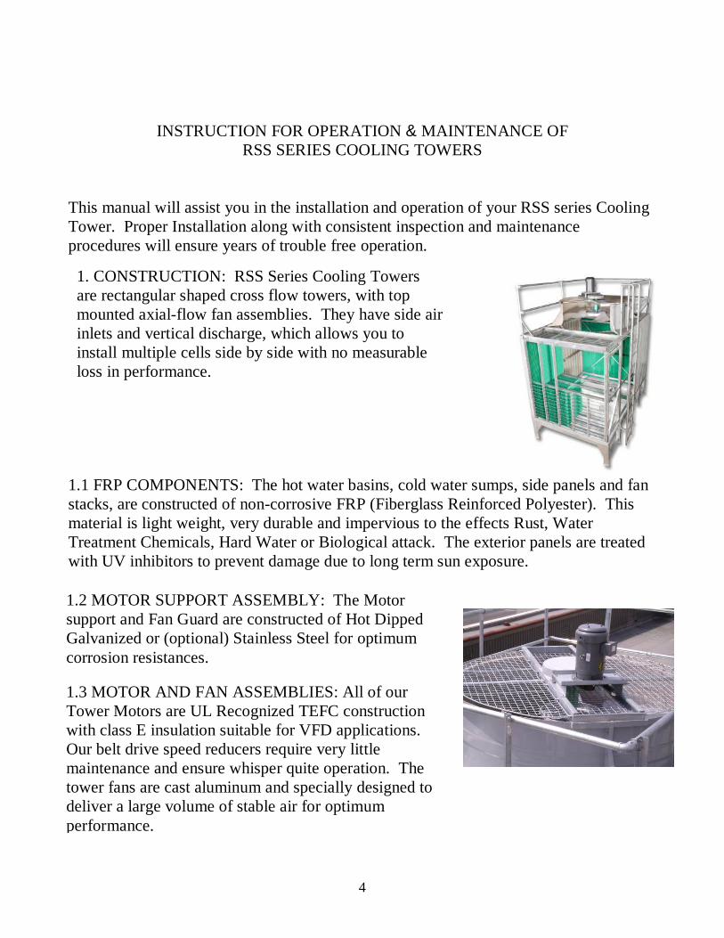
1.1 FRP COMPONENTS: The hot water basins, cold water sumps, side panels and fan stacks, are constructed of non-corrosive FRP (Fiberglass Reinforced Polyester). This material is light weight, very durable and impervious to the effects Rust, Water Treatment Chemicals, Hard Water or Biological attack. The exterior panels are treated with UV inhibitors to prevent damage due to long term sun exposure.
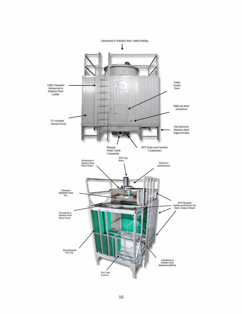
1. CONSTRUCTION: RSS Series Cooling Towers are rectangular shaped cross flow towers, with top mounted axial-flow fan assemblies. They have side air inlets and vertical discharge, which allows you to install multiple cells side by side with no measurable loss in performance.
1.2 MOTOR SUPPORT ASSEMBLY: The Motor support and Fan Guard are constructed of Hot Dipped Galvanized or (optional) Stainless Steel for optimum corrosion resistances.
1.3 MOTOR AND FAN ASSEMBLIES: All of our Tower Motors are UL Recognized TEFC construction with class E insulation suitable for VFD applications. Our belt drive speed reducers require very little maintenance and ensure whisper quite operation. The tower fans are cast aluminum and specially designed to deliver a large volume of stable air for optimum performance.
5
. (add fill photo
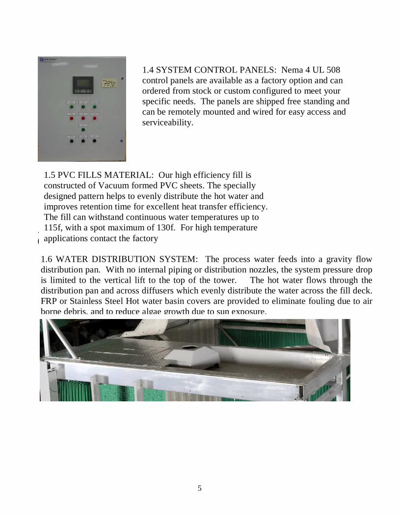
1.4 SYSTEM CONTROL PANELS: Nema 4 UL 508 control panels are available as a factory option and can ordered from stock or custom configured to meet your specific needs. The panels are shipped free standing and can be remotely mounted and wired for easy access and serviceability.
1.5 PVC FILLS MATERIAL: Our high efficiency fill is constructed of Vacuum formed PVC sheets. The specially designed pattern helps to evenly distribute the hot water and improves retention time for excellent heat transfer efficiency. The fill can withstand continuous water temperatures up to 115f, with a spot maximum of 130f. For high temperature applications contact the factory
1.6 WATER DISTRIBUTION SYSTEM: The process water feeds into a gravity flow distribution pan. With no internal piping or distribution nozzles, the system pressure drop is limited to the vertical lift to the top of the tower. The hot water flows through the distribution pan and across diffusers which evenly distribute the water across the fill deck. FRP or Stainless Steel Hot water basin covers are provided to eliminate fouling due to air borne debris, and to reduce algae growth due to sun exposure.

6
2. CHOOSING THE PROPER TOWER LOCATION RSS Series Cooling Towers are designed for outdoor installation only. To achieve the best possible performance, it is important to choose a suitable installation location.
If prevailing winds are consistent and measurable, the tower should be positioned so that the air inlets louvers are at right angle to the wind direction. This will ensure sufficient and equal air flow through both fill decks. In addition, it will help to reduce drift and the fouling of the tower fill caused by airborne materials.
1.7 LADDERS, WALKWAYS AND SAFETY RAILINGS: All access ladders, internal walkways and safety railings are constructed of Hot Dipped Galvanized or (optional) Stainless Steel for optimum corrosion resistances. Ladders and walkways are designed to be safe and to allow easy access to the tower during routine inspection, maintenance and repair.
2.1 SUPPLY AIR: The amount and condition of the supply air is very important to cooling tower performance. When selecting an installation site, be certain that there is sufficient airflow to the tower inlet. If the tower it to be installed in a confined space, you must be certain that you have sufficient CFM available to satisfy the design requirement for you tower. The tower should also be positioned so that the tower exhaust is not restricted which could cause recirculation of saturated discharge air, and significantly impact performance

7
2.2 DISCHARGE AIR: It is very important that the tower exhaust be unobstructed allowing the saturated discharge air to flow freely into the atmosphere. Installing the tower indoor or under an overhang will cause recirculation of the saturated discharge air and reduce the tower performance. In addition, condensations could occur which may potentially cause damage to surrounding materials.
3.0 MOUNTING YOUR TOWER: RSS Series Cooling Towers can be mounted at ground level or on an elevated platform as necessary. The mounting surface must be level and sufficient to support the weight of the tower as shown in the specifications. Refer to the Local Mechanical Code for specific anchoring requirements in your area. 3.1 ANCHORING: For either ground level or elevated installations, the tower must be anchored in place. This will reduce stress on the tower and any connected components casued by unexpected shifts in the mounting surface.
2.3 SERVICE ACCESS: RSS Series Cooling Towers are very reliable and need minimal maintenance. When selecting an installation location, be certain that you will have sufficient access in order to perform routine inspections and repairs as needed. Access doors and ladders should be positioned so that may be used in a safe and secure manner. If the tower is to be mounted above ground, refer to the prevailing mechanical code to ensure the safety of inspection and service personnel.

8
3.2 VIBRATION ISOLATION: Although vibration Isolators are not required, it is acceptable to use them as prescribed by local mechanical code. Consult the factory for specific on your model as necessary. If Isolators are employed, you would also need to use flexible connectors in the associated water lines.
4. PIPING CONNECTIONS Piping connections are limited to Hot Water Supply, Cold Water Return, Drain, Overflow and Fresh Water Make up. All piping must be in accordance with all prevailing plumbing codes and requirements. All external piping must be independently supported. The factory installed fluid connections, basin supports and safety railings are not engineered to carry the load of system piping or other mechanical devices. 4.1 SUPPLY AND RETURN PIPING: Must be sized properly to handle the system design flow with a minimum pressure drop. All piping must be independently supported to avoid placing undo stress on the tower fittings. There are (2) Hot Water Supply feeds on the top of each tower cell. It is recommended that balancing valves be installed in the hot water supply lines to ensure equal flow across the fill decks. There is (1) Cold Water Return per tower cell. The piping should be configured to ensure gravity (NPSH) to the system pump. For multi-cell installations, balancing values should be installed on each cold water return line to ensure balanced suction from each basin. 4.2 DRAIN AND OVERFLOW PIPING: The tower drain and overflow connections should be plumbed to an approved floor sink or sewer connection. The quality of your discharge water will be dependent on your water treatment chemicals and you should ensure that they are approved for this purpose.
9
4.4 BASIN EQUALIZER LINES: For multiple cell installations, it may be necessary to install an equalization line to ensure that all cells maintain the same cold water sump level. If equalizer lines are used, an isolation valve should be installed to allow each cell to be operated and serviced independently as required 5. ELECTRICAL CONNECTIONS; All electrical connections need to be in accordance with all prevailing Electrical Codes and requirements. Line voltage terminates directly at the tower motor. 5.1 MOTOR SPECIFICAITONS: All RSS Series Cooling Towers are equipped with UL Recognized, Class E, TEFC Motors. The motors must be connected to an overload protected device, not to exceed 125% of the RLA of the motor. Motors can be installed across the line but soft start or VFD installation is recommended to maximize motor efficiency and mechanical reliability. 5.2 WIRING: All wiring must be properly sized for the design load, and shielded per the prevailing codes. Conduits or chases should be positioned so they will not interfere with periodic inspection and maintenance activities. 5.3 AUXILLARY CONTROLS: All auxiliary controls need to be rated for cooling tower duty and should be in weather tight enclosures. UL508 control panels are available from the factory as a stand alone option. These panels need to be field mounted and wired in accordance with the prevailing electrical codes and requirements.
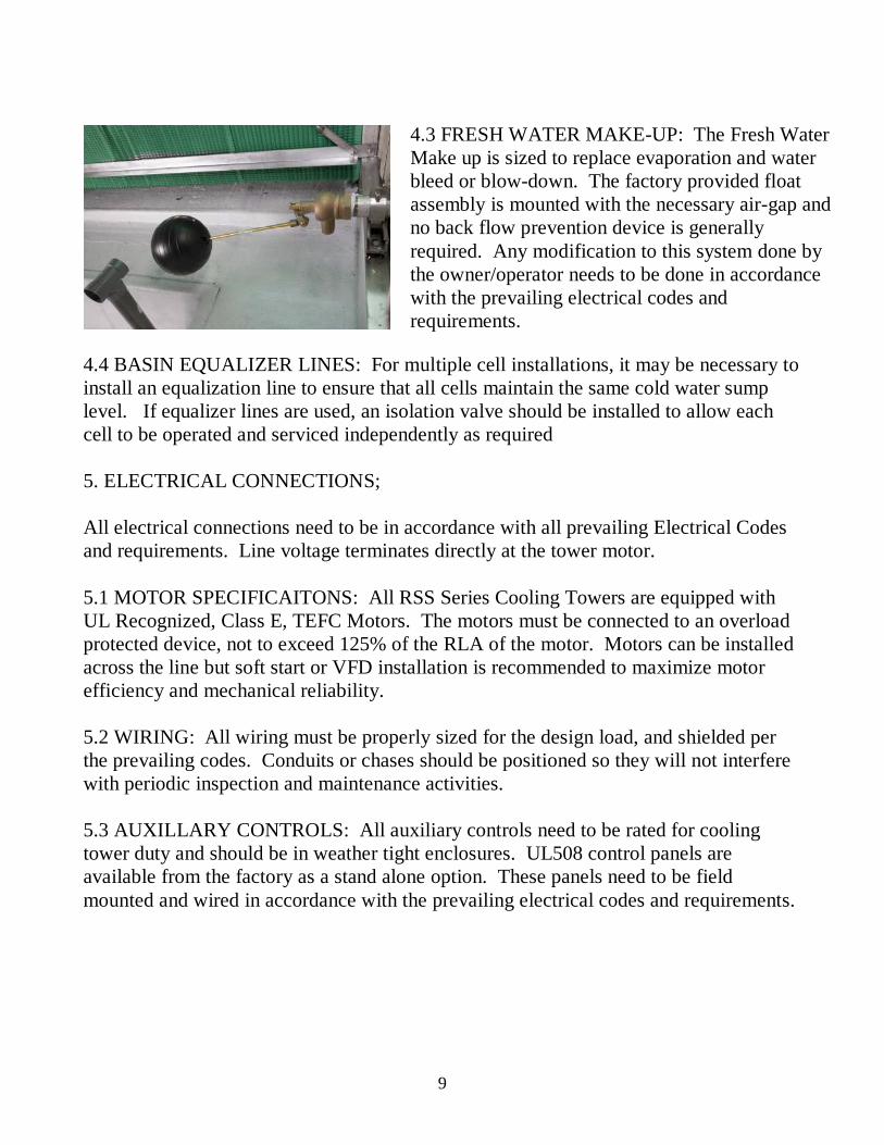
4.3 FRESH WATER MAKE-UP: The Fresh Water Make up is sized to replace evaporation and water bleed or blow-down. The factory provided float assembly is mounted with the necessary air-gap and no back flow prevention device is generally required. Any modification to this system done by the owner/operator needs to be done in accordance with the prevailing electrical codes and requirements.

10
6.0 PRE-STARTUP PROCEDURES: Before starting your tower, you should perform the following Pre-Startup Procedures. 6.1 MECHANICAL INSPECTION a. Before performing a mechanical inspection, ensure that the fan motor disconnect is in the off position and locked. b. Visually inspect the tower frame and support structure to ensure everything is properly aligned and all fasteners are in place.
e. Make sure the hot water return lines are in the proper position and that the distribution hoods are in place. Open all hot water return balancing valves. f. Verify that the tower Fan Guard is in place and secure. g. Check the Overflow and Drain Lines, making sure any valves are in the closed position. h. Check to ensure that all the bolts on the Cold Water Return Flange are properly tightened. Open any return line diverting valves. i. Make sure that all the inlet louvers are in place and properly aligned.
c. Inspect the Fan Blade making sure the retaining nut and u-bolts are tight. Spin the blade by hand making sure it is free of obstructions
d. Inspect the belt drive belts and adjust if necessary. Use the tensioning bolts on either side of the motor plate to achieve the proper deflection. No more than ¼” deflection is recommended. If you need to align the pulleys, loosen the main pulley set screw and raise or lower as necessary
11
6.2 CLEANING a. Remove any visible debris from the cold water basin. b. Rinse the hot water distribution pans ensuring that all of the distribution holes are clear. Let the water flow for 2 to 3 minutes to flush any foreign material from the fill deck. c. Using a scrub brush or push broom, rinse and clean the cold water basin. d. Open the Basin Drain and rinse/flush the remaining debris from the cold water basin. 6.3 ELECTRICAL INSPECTION a. Visually inspect the Fan and Pump motor wiring to ensure it is properly connected and that all terminal box covers are installed. b. Inspect all wiring chases and conduits to ensure they are properly sealed and secured. c. Confirm that all short circuit protection is in place and functional. 6.4 TRIAL WATER CIRCULATION a. Fill the tower basin with water. You can use the float valve, but secondary hoses will speed the process. b. Adjust the float valve so that the bottom of the fill deck is slightly submerged (about 1/4”) and the valve shuts off. c. Visually inspect the tower basin for leaks. If leaks are evident, notify your installing contractor or the factory at once. d. Energize the system circulating pump.
12
e. Inspect your piping and ensure there are no measurable leaks. If leaks are present, turn off the pumps and make the necessary repairs. f. Inspect the Hot Water Return Basins and adjust the balancing valves as necessary to get even flow across both fill decks. g. Inspect the Water Level in the cold water basin. The water level will likely fall below the bottom of the fill deck, so you will need to allow that to equalize. (Note, If any of the system supply piping is above the basin level, you could get water flooding back at shutdown. Check valves will need to be installed if this occurs) h. Once you are happy with the circulating flow, you are ready to test the fan operation. 6.5 TRIAL FAN TEST a. Before testing the fan, turn off the circulation pump b. Energize the Tower Fan c. Listen for any signs of mechanical contact, vibration or belt noise. Identify and adjust as necessary. d. Energize the circulating pump e. Check the current draw on the fan motor to ensure it is within the name plate range. (If the amp draw is higher than the FLA rating, it may be necessary to inspect and adjust the pitch of the fan blade.) (Also Note: the fan motor will draw higher amps when the water is turned off, so test accordingly.) You Cooling Tower is now ready for on-line operation.
13
7.0 TOWER MAINTENANCE 7.1 Post Start-up Inspection: Within the first week of operation the tower should be fully inspected to ensure that all systems are operating normally and make any necessary adjustment a. Motor and Fan Assembly: Inspect the drive belts to ensure that they are properly aligned and adjusted. You should see approximately ¼” deflection at the mid-span of the belt travel. There is a tension adjustment on the outside of the motor assembly. Also check to ensure the fan blade is free of debris and that the u-bolts are tight. b. Water Distribution System: Inspect the water distribution pans and remove any debris that my have accumulated. Also make sure that you have equal flow across both fill decks, and adjust if necessary. Look for early signs of algae and consult your water treatment provider as necessary. c. Water Level, Water Make-up: Inspect the basin water level and ensure that approximately 1/4'” of the fill material is below the water line. Adjust the water make-up as necessary. Note: If the fill is not submerged, inlet air will bypass the fill deck and performance will be compromised. d. Water Quality: Take samples of both the recalculated flow and the tower make-up water. Have the samples analyzed to determine if adjustments to the chemical feed or the tower bleed are required. Consult your water treatment provider for assistance as needed. If any adjustments are made, a follow up inspection may be necessary. 7.2 Periodic Inspection: Your cooling tower should be visually inspected regularly to maintain peak performance. The inspection frequency will vary based on the duty cycle of the tower and environmental factors. It is recommended that the tower be inspected monthly during the first year of operation with the frequency adjusted as necessary. 7.3 Lubrication: The belt reducer bearings should be lubricated every 3 months or as necessary through the fittings provided. 7.4 Tower Frame: The tower frame is constructed of either hot-dipped galvanized or stainless steel. No regular maintenance is required, but a regular inspection is
14
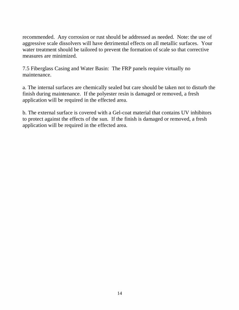
recommended. Any corrosion or rust should be addressed as needed. Note: the use of aggressive scale dissolvers will have detrimental effects on all metallic surfaces. Your water treatment should be tailored to prevent the formation of scale so that corrective measures are minimized. 7.5 Fiberglass Casing and Water Basin: The FRP panels require virtually no maintenance. a. The internal surfaces are chemically sealed but care should be taken not to disturb the finish during maintenance. If the polyester resin is damaged or removed, a fresh application will be required in the effected area. b. The external surface is covered with a Gel-coat material that contains UV inhibitors to protect against the effects of the sun. If the finish is damaged or removed, a fresh application will be required in the effected area.
15
RSD warrants our RSS Cooling Towers to be free of defects in material and/or
workmanship to the extent, but only the extent, set forth below:
(A) F.R.P. components for ten (10) years* from date of installation. To be replaced or repaired
as needed.
(B) P.V.C. fill material for two (2) years from date of installation. To be replaced as needed.
(C) All electrical, mechanical and non-F.R.P. structural components for one (1) year from date of
installation. To be replaced or repaired as needed.
THE FOREGOING EXPRESSED WARRANTY IS IN LIEU OF ALL OTHER WARRANTIES, EXPRESSED, IMPLIED, OR STATUTORY (INCLUDING, BUT NOT LIMITED TO, WARRANTIES OF
MERCHANTABILITY AND FITNESS FOR ANY PARTICULAR PURPOSE.)
R.S.D. SHALL IN NO EVENT BE LIABLE FOR ANY CONSEQUENTIAL, INCIDENTAL OR SPECIAL DAMAGES AND/OR EXPENSES. RSD Cooling Tower Division – 1201 Montery Pass Rd – Montery Park, Ca 91754 Ph 323-264-2800 Fx 949-461-7459 email [email protected]
A Division of Refrigeration Supplies Distributor – 26021 Atlantic Ocean Dr - Lake Forest, Ca – 92630
16