Operational Technology General Requirements
24
Operational Technology General Requirements Document Number: 1 - 10 - FR - 01 VERSION 1.0 June 2018
Transcript of Operational Technology General Requirements
Operational Technology General Requirements
Document Number: 1-10-FR-01
VERSION 1.0 June 2018

Intellectual property rights and disclaimer
This document is published in accordance with the requirements of Chapter 5 of the National Electricity Rules (NER). It is a functional requirement document only and is not intended to contain any comprehensive or project specific designs, specifications or other information. Whilst care has been taken to ensure that the contents of this document are accurate, ElectraNet Pty Limited (ElectraNet) does not represent or warrant that the information contained in this document is complete, accurate or adequate in any respect. ElectraNet reserves the right to amend this document at any time without notice to any person.
The user must carefully examine and check the information contained in this document and carry out its own independent technical and legal assessment and due diligence to ensure that the information in this document is used appropriately and that in doing so, all requirements (including requirements at law) are satisfied. For the avoidance of any doubt, the publication of this document does not limit or detract from the user’s obligations at law, and does not and will not give rise to any claim (including, without limitation, in contract, tort, equity, under statute or otherwise) against ElectraNet or any of its ‘Associates’ (as that term is defined in Corporations Act 2001 (Cth)).
All intellectual property rights (including without limitation any copyright, patents, logos, designs, circuit layouts, trademarks, moral rights and know how) in the whole and every part of this document are owned by or licenced to ElectraNet. Except as expressly provided in Chapter 5 of the NER or with the prior written consent of ElectraNet, the contents of this document cannot be used, transferred, copied, modified or reproduced in whole or in part in any manner or form or in any media.
© ElectraNet Pty Limited. All rights reserved.

Operational Technology General Requirements l Document No: 1-10-FR-01
Security Classification: Public WHEN PRINTED THIS DOCUMENT IS UNCONTROLLED
Date: June 2018
Version: 1.0 ©ElectraNet Pty Limited 2018 – all rights reserved
Page 3 of 24
Contents
1. Definitions .................................................................................................................. 4
2. Operational Technology Overview .......................................................................... 6 2.1 Components .................................................................................................................. 6 2.2 Approved Service Catalogue ....................................................................................... 6 2.3 Bandwidth Required Per Substation ........................................................................... 8 2.4 Service Performance .................................................................................................... 8 2.5 Bearer Options .............................................................................................................. 9
3. Operational Technology General Requirements .................................................. 10 3.1 Safety (and Environmental) Requirements ................................................................10 3.2 Planning and Design Requirements ...........................................................................10
3.2.1 Point-to-Point Radio Systems .................................................................................12 3.2.2 Optical Fibre Cables ...............................................................................................12 3.2.3 Digital Line Terminating Equipment ........................................................................12 3.2.4 Power Line Carrier Systems ...................................................................................13 3.2.5 Network Synchronisation ........................................................................................13
3.3 Constructability Requirements ...................................................................................14 3.4 Maintainability Requirements .....................................................................................15
3.4.1 Point-to-Point Radio Systems .................................................................................16 3.4.2 DC Power Supply (-48VDC) ...................................................................................16
3.5 Maintenance Spares ....................................................................................................16 3.6 Operability Requirements ...........................................................................................16 3.7 Performance Requirements ........................................................................................17
3.7.1 Point-to-Point Radio Systems .................................................................................17 3.8 Testing and Validation Requirements ........................................................................17
3.8.1 Point-to-Point Radio Systems .................................................................................17 3.8.2 Optical Fibre Cable .................................................................................................18 3.8.3 Power Line Carrier (PLC) ........................................................................................18 3.8.4 PDH Digital Path .....................................................................................................18 3.8.5 SDH Digital Path .....................................................................................................19 3.8.6 E1 Service ..............................................................................................................19 3.8.7 C37.94 (G.703 64k) Service ...................................................................................19 3.8.8 Ethernet Service .....................................................................................................19 3.8.9 Telephone Service ..................................................................................................20 3.8.10 DC Power Supply (-48VDC) ...................................................................................20
3.9 Asset Information Requirements ................................................................................21
Appendix A Generic OT Deployment at Substations ................................................ 23
Operational Technology General Requirements l Document No: 1-10-FR-01
Security Classification: Public WHEN PRINTED THIS DOCUMENT IS UNCONTROLLED
Date: June 2018
Version: 1.0 ©ElectraNet Pty Limited 2018 – all rights reserved
Page 4 of 24
1. Definitions
In this document the following words and expressions will have the following meanings:
Item Meaning
ACMA Australian Communications and Media Authority.
AEMC Australian Energy Market Commission.
AEMO Australian Energy Market Operator.
AER Australian Energy Regulator.
BER Bit Error Rate
BISO Bring-Into-Service Objective.
CCM Communications Cabling Manual.
Contractor A contractor engaged by ElectraNet or a Customer (including a third party IUSA provider engaged by a Customer or any contractor engaged by such third party IUSA provider) to perform any design, construction or related services in relation to assets or infrastructure which are connected, or to be connected, to ElectraNet’s transmission network
Customer A party who wants to establish or modify a connection to ElectraNet’s transmission network but does not include a third party IUSA provider
DC Direct Current
Designer A Contractor who performs design services in relation to assets or infrastructure which are connected, or to be connected, into ElectraNet’s transmission network.
ETCDB ElectraNet Telecommunications Configuration DataBase.
FAT Factory Acceptance Testing.
FLHIA Functional Location Hazard Identification and Assessment.
FunLoc Functional Location.
HMI Human Machine Interface
HSB Hot Stand-By.
HSM High Speed Monitoring
IETF Internet Engineering Task Force.
ITP Inspection and Test Plans.
LoS Line of Sight.
LSA Loud Sounding Alarm.
LSPM Light Source and Power Meter.

Operational Technology General Requirements l Document No: 1-10-FR-01
Security Classification: Public WHEN PRINTED THIS DOCUMENT IS UNCONTROLLED
Date: June 2018
Version: 1.0 ©ElectraNet Pty Limited 2018 – all rights reserved
Page 5 of 24
Item Meaning
MAIT Mobile Asset Inspection Tool – an electronic data collection tool provided by ElectraNet (this provides field data collection and data transfer to SAP).
MSP Maintenance Service Provider.
NER National Electricity Rules.
OFCS Optical Fibre Communication Systems.
OGPW Optical Ground Wire
OT Operational Technology.
OTDR Optical Time Domain Reflectometer.
PDH Plesiochronous Digital Hierarchy.
PLC Power Line Carrier.
PSDCS Standard for Power System Data Communications.
PSTN Public Switched Telephone Network
RF Radio Frequency
SAP Systems, Applications and Products, which is a software application used by ElectraNet for asset management functions.
SAT Site Acceptance Testing.
SCADA Supervisory Control And Data Acquisition.
SDH Synchronous Digital Hierarchy.
SMSC System Monitoring and Switching Centre.
SNR Signal-to-Noise Radio.
third party IUSA Has the same meaning as defined in the National Electricity Rules
TM Transmission and Multiplexing.

Operational Technology General Requirements l Document No: 1-10-FR-01
Security Classification: Public WHEN PRINTED THIS DOCUMENT IS UNCONTROLLED
Date: June 2018
Version: 1.0 ©ElectraNet Pty Limited 2018 – all rights reserved
Page 6 of 24
2. Operational Technology Overview
The substation Operational Technology (OT) deployment comprises of the, infrastructure, systems and services required to provide secure, resilient and reliable communication and information services as mandated by Australian Energy Market Commission (AEMC), National Electricity Rules (NER) and interpreted by the Australian Energy Market Operator (AEMO) Standard for Power System Data Communications (PSDCS) and by ElectraNet for safe, secure and reliable electricity network operations and maintenance.
2.1 Components
The operating technology deployment at a substation comprises of the following equipment and infrastructure as required:
1. Dedicated building, nominally a transportable, which contains the OT assets, including dedicated -48V DC power supplies.
2. Inter-site bearers (optical or microwave) and associated infrastructure, for example a radio tower for microwave bearers, pit/pipe underground infrastructure for optical fibre bearers, etc.
3. Wide area network equipment (including multiplexers, routers and switches).
4. Local area equipment (including IP switches, wi-fi access point).
5. Telephony equipment (including handsets and external loud sounding alarms).
6. Telemetry assets including, SCADA gateway, power quality monitors, weather monitors, pollution monitors, etc. as required.
7. Cyber-security equipment.
8. Site Server for engineering management and HMI.
2.2 Approved Service Catalogue
Table 2-1 below shows the list of services, the source of requirements and the minimum performance standards.
Table 2-1: Approved Service List
Regulatory
Data Services Min Performance Standard
Source of Requirement
Protection [X + Y], incl sever trips
Availability: 99.9% (per path)
Redundancy: Yes (physical and logical path)
Jitter: < 1ms from relay to relay
Data Payload: 64kb
Latency: Real time, 5 - 15 ms
Bandwidth: 64kbps (as real time)
Protocols: C37.94
NER, Schedule 5.1, clause S5.1.2.1 (d)
NER, Schedule 5.1, clause S5.1.9 (c) & (d)
NER, Schedule 5.1a, Table S5.1a.2

Operational Technology General Requirements l Document No: 1-10-FR-01
Security Classification: Public WHEN PRINTED THIS DOCUMENT IS UNCONTROLLED
Date: June 2018
Version: 1.0 ©ElectraNet Pty Limited 2018 – all rights reserved
Page 7 of 24
Supervisory Control and Data Acquisition
Availability: 99.97%
Redundancy: Sufficient Redundancy
Data Payload: 64kb
Latency: near real time, less than 1 second
Bandwidth: 64kbps
Protocol: DNP over IP
PSDCS 2.3
PSDCS 3.1, Table 3
PSDCS 3.2
Control Run Back Scheme
[X + Y]
As per SCADA requirement Transmission Connection Agreement (TCA) with Customers
Voice
["on network" + "off network"]
Availability: 99.9% (per path)
Redundancy: Yes (physical and logical path)
Data Payload: 64kb per voice service
Latency: real time
Bandwidth: 128kbps (as real time)
Protocol: IP
NER, clause 4.11.2 (a)
NER, clause 4.11.3 (c) Industry ‘best practice’ ElectraNet OH&S
Operational Data Services
Min Performance Standard Source of Requirement
High Speed Monitoring
Availability: 99.97%
Redundancy: Sufficient Redundancy
Data Payload: 64kb
Latency: near real time, less than 4 seconds
Bandwidth: 64kbps
Protocol: DNP over IP
HSM (AEMO)
Power System Fault Restoration (during outage)
Availability: 99.98%
Redundancy: No, but required to meet availability
Data Payload: 100kb to 100Mb or greater
Latency: not real time
Bandwidth: 2Mbps
Protocol: IP
Internal;
Fault Understanding within 1 hour
Power System Fault Analysis (post event)
Availability: best efforts
Redundancy: No
Data Payload: 100kb to 100Mb or greater
Latency: not real time
Bandwidth: best efforts
Protocol: IP
Internal
Substation Remote Configuration Management
As above, but
Data Payload: 100kb to 1Mb
Protocol: IP
Internal
Substation Remote Condition Monitoring
As above, but
Data Payload: 10kb to 100kb
Protocol: IP
Internal

Operational Technology General Requirements l Document No: 1-10-FR-01
Security Classification: Public WHEN PRINTED THIS DOCUMENT IS UNCONTROLLED
Date: June 2018
Version: 1.0 ©ElectraNet Pty Limited 2018 – all rights reserved
Page 8 of 24
Other Data Services
Min Performance Standard Source of Requirement
Dynamic Rating (including weather stations)
Availability: NA, fall back to static ratings.
Redundancy: No
Data Payload: 10kb to 100kb
Latency: near real time, less than 4 seconds
Bandwidth: 64kbps
Protocol: IP
Internal
Surveillance (Video & Perimeter Security)
Availability: 99.9%
Redundancy: No, but required to meet availability
Data Payload: 2-20Mb or greater
Latency: real time
Bandwidth: 12Mbps
Protocol: IP
Internal
(policy under development)
Security:
Building & Fire,
Cyberkeys
Availability: 99.9%
Redundancy: No, but required to meet availability
Data Payload: 64kb
Latency: real time
Bandwidth: 64kbps
Protocol: IP
Internal
Situational Awareness
(OPSWAN Cameras)
Availability: Best endeavours
Redundancy: No
Data Payload: 1Mb
Latency: real time
Bandwidth: 1Mbps
Protocol: IP
Internal
Construction & Maintenance Comms
Availability: Best endeavours
Redundancy: No
Data Payload: 100Mb
Latency: not real time
Bandwidth: 10Mbps
Protocol: IP
Internal
2.3 Bandwidth Required Per Substation
The combined bandwidth requirement for all services listed in Table 2-1 is 25 Mbps, per substation. An additional 2 Mbps is required for OT network performance management, producing an overall bandwidth of 27Mbps per substation.
2.4 Service Performance
Since the overall OT network is made up of a series of links, the end to end network availability will always be less than that of the individual links. Therefore the individual link availability required is extremely high. In many cases this can only be achieved via either equipment and/or path diversity. Protection, SCADA, Telephony and Power System Fault Restorations services can only achieve the

Operational Technology General Requirements l Document No: 1-10-FR-01
Security Classification: Public WHEN PRINTED THIS DOCUMENT IS UNCONTROLLED
Date: June 2018
Version: 1.0 ©ElectraNet Pty Limited 2018 – all rights reserved
Page 9 of 24
availability standards required if an alternate path is provided. As per Table 2-1, the bandwidth required for the alternate path is 2.25 Mbps per substation.
In addition, the services that need to be carried impose a number of strict requirements on the underlying OT network in relation to:
1. Latency: the time required for the entire payload to get to the other end. This is a function of the available bandwidth, packet length, the transmission medium, and the processing speed of intermediate and terminal equipment.
2. Jitter: the variability in the latency between successive payload transmission
3. Availability: the ratio of the time a system or component is functional to the total time it is required or expected to function.
These performance requirements impose limitations on the OT bearer options available at the substations. For more details on the Protection system requirements refer to 1-09-FR-01.
All services must meet the performance requirements as per IEEE Std 1646-2004- IEEE Standard Communication Delivery Time Performance Requirements for Electric Power Substation Automation.
2.5 Bearer Options
In order to meet the performance requirement for the carriage of regulated services (AER and AEMO services), ElectraNet will need to provide two high speed bearers.
However, due to the fact that new substations break into the existing network, the bearer also needs to carry traffic required for other substations further out in the network. As a result, these bearers also need to be high capacity.
The preferred solution is to install two fibre bearers. This is reasonably cost effective to do, especially on the 275kV transmission network as most of the lines have OGPW installed already. Where this is not possible, the next preferred solution is a one fibre bearer and one radio, or possible two radio bearers. In all cases, the lowest long run cost option (in particular low levels of ongoing operations, maintenance and replacement costs) will be chosen.
For substation at the end of the network, generally as a result of new line being constructed as a spur off the main network, the high speed bearer must be provided as OGPW as part of new line. As it is not a nodal substation, and if it is only a 132kV or less line, the second bearer can be provided as a combination of a PLC and a leased service. Again, in this instance, the lowest long run cost option (in particular low levels of ongoing operations, lease, maintenance and replacement cost) will be chosen.

Operational Technology General Requirements l Document No: 1-10-FR-01
Security Classification: Public WHEN PRINTED THIS DOCUMENT IS UNCONTROLLED
Date: June 2018
Version: 1.0 ©ElectraNet Pty Limited 2018 – all rights reserved
Page 10 of 24
3. Operational Technology General Requirements
ElectraNet must provide and maintain communications facilities as required by the Australian Energy Market Commission (AEMC) National Electricity Rules (NER) and interpreted by the Australian Energy Market Operator (AEMO) Standard for Power System Data Communications (PSDCS).
This section details the general requirements as applicable to all the various assets and component that make up the OT deployment at a substation. Some assets have additional specific requirements, and they are highlighted specifically within subsections under the general sections below.
3.1 Safety (and Environmental) Requirements
All equipment, devices and components for the ElectraNet Operational Technology Network must be suitable for sale and use in Australia, meeting all regulatory and legislative requirements.
These include, but are not limited to;
AS/NZS 3000 Wiring Rules
AS/CA S009 Installation requirements for Customer cabling (Wiring rules)
Radiocommunications Act 1992
Radiocommunications (Electromagnetic Radiation — Human Exposure) Standard 2014
AS/NZS 2211.2 Safety of laser products - Part 2: Safety of optical fibre communication systems (OFCS)
Contractor (and subcontractor(s)) access to all ElectraNet sites must be pursuant to the rules, conditions and requirements as detailed in the ElectraNet “Asset Access Manual” (ElectraNet Document No P6070).
The Designer must implement Safety in Design activities in accordance with ElectraNet’s Safety in Design Procedure.
In support of achieving Safety in Design, the detail design process must also comply with the requirements of ElectraNet’s Plant Lifecycle Hazard Management Procedure.
The appropriate level of supervision must be provided to meet the requirements of the work, especially within the substation environment that requires specialised work practices.
3.2 Planning and Design Requirements
The primary planning requirement is to ensure there is no common point of failure along any of the communication path between the equipment that carries the Set X line protection and the Set Y line protection. Further, this diversity and redundancy requirement is also extended to the main and backup SCADA

Operational Technology General Requirements l Document No: 1-10-FR-01
Security Classification: Public WHEN PRINTED THIS DOCUMENT IS UNCONTROLLED
Date: June 2018
Version: 1.0 ©ElectraNet Pty Limited 2018 – all rights reserved
Page 11 of 24
services and the main and backup telephony services, including for the National Grid Metering service.
This requires the provision of two separate suites of OT equipment within the site, separate and physically diverse bearers leaving the site, and separate and diverse routing along the intra-site optical and copper cables within the site.
It also requires that equipment must be powered via dual -48V DC power supplies. Equipment that requires 110V DC must be powered by a 48 to 110V DC-DC converter.
All equipment for the ElectraNet OT Network should be suitable for use in a power utility substation environment.
These include, but are not limited to
IEEE 1613-2003 Environmental and Testing Requirements for Communications Networking Devices in Electric Power Substations
IEC-61850:2018 Communication networks and systems for power utility automation
RALI : FX 3 Microwave Fixed Services Frequency Coordination, Radiocommunications Assignment and Licensing Instruction
ITU-T G652.D (2016) Characteristics of a single-mode optical fibre and cable
ISO/IEC 11801-OM3 Information technology - Generic cabling for Customer premises
ETSI 300 147 TM; Synchronous Digital Hierarchy (SDH) Multiplexing structure
ETSI ETR 241 TM; Functional architecture of 2 Mbit/s based PDH transport networks
ITU-T Recommendations pertinent to the SDH/PDH environment;
G.702, G.703, G.704, G.707, G.711, G.723, G.783, G.957
ITU-T Rec G.811 Timing characteristics of primary reference clocks
ISO/IEC 11573:1994 Telecommunications and information exchange between systems -- Synchronization methods and technical requirements for Private Integrated Services Networks
EN 300 462 TM; Generic requirements for synchronization networks;
All ElectraNet OT Network planning and design work must be done within the ETCDB.

Operational Technology General Requirements l Document No: 1-10-FR-01
Security Classification: Public WHEN PRINTED THIS DOCUMENT IS UNCONTROLLED
Date: June 2018
Version: 1.0 ©ElectraNet Pty Limited 2018 – all rights reserved
Page 12 of 24
In addition, all equipment must be able to be fully integrated into ElectraNet’s existing OT network management systems.
3.2.1 Point-to-Point Radio Systems
All single bearer ElectraNet microwave radio links must be 1+1 HSB hardware configuration. All multiple bearer ElectraNet microwave radio links must be an N+1 Protected hardware configuration. All ElectraNet microwave radio links must have a validated minimum fade margin of 30 dB.
Point-to-Point radio links are affected by environmental (climatic / atmospheric) influences, thus the design of Point-to-Point microwave radio systems must comply with and meet the reliability and availability standards imposed by ElectraNet’s operational requirements.
The Point-to-Point radio link design must:
1. Apply an accurate representation of the actual path's characteristics.
2. Path engineering to meet the minimum clearance criteria and to determine the risks and effects of possible RF signal disturbance (e.g. reflection, refraction, diffraction, etc.).
3. Link engineering to model the specific radio equipment feeder cables and antennas to accurately determine the fade margin and associated link availability.
Desktop studies only provide a useful indication that a radio link path may be suitable. A LoS survey must be conducted to verify and confirm the path validity of all new radio links (particularly the identification of localised obstacles that may impinge into the Radio LoS).
Telecommunications industry standard radio path software planning tools such as ‘Pathloss™ or T-Path™’ must be used for desktop radio link design analysis.
The Contractor’s radio designer must be competent with radio propagation theory and calculation methodology for determination of the radio link performance and path losses.
3.2.2 Optical Fibre Cables
The standard minimum specification for intersite optical fibre cable must be single mode in compliance with ITU-T G652.D. The standard minimum specification for intra-site (i.e. between buildings at a substation site) optical fibre cable must be 850nm multimode in compliance with ISO/IEC 11801-OM3.
3.2.3 Digital Line Terminating Equipment
SDH ADMs must be utilised as Digital Line Terminating Equipment entities for both optical and radio based SDH links.
All optical links must have their optical link budget determined and strictly adhered to.
Operational Technology General Requirements l Document No: 1-10-FR-01
Security Classification: Public WHEN PRINTED THIS DOCUMENT IS UNCONTROLLED
Date: June 2018
Version: 1.0 ©ElectraNet Pty Limited 2018 – all rights reserved
Page 13 of 24
Optical links must be dual fibre (core) arrangement.
3.2.4 Power Line Carrier Systems
As Power Line Carrier (PLC) systems only provide limited bandwidth capabilities, they must only be deployed by exception as an alternate path for 132kV lines that spur of the main network (i.e. do not connect to nodal substations).
If PLC systems are selected to be the secondary bearer, then:
a) Only analogue Power Line Carrier systems must be deployed within the ElectraNet Powerline Transmission Network. Digital Power Line Carrier systems have been experimented with, but their operational performance attributes have been found unsatisfactory within the South Australian environment (in which the ElectraNet Powerline Transmission Network operates), thus must not be deployed within the ElectraNet Powerline Transmission Network.
b) The Power Line Carrier system's carrier frequencies can be reused throughout the ElectraNet Powerline Transmission Network, provided that PLC systems using the same carrier frequencies are isolated sufficiently; namely; by two line section or one line section and a transformer.
c) The PLC system must be phase to phase coupled to two phases of the powerline. Phase to earth coupling must not be used for either single or multiphase coupling of PLC systems.
d) For 132 kV powerlines, the PLC systems must be two phase coupled to the R & S phases.
e) The PLC system may be coupled to three phases of the powerline under special applications that require lower attenuation than can be provided by two phase coupling.
f) PLC systems must be provided with two 4 kHz channel payload capability.
g) All protection signals carried over the PLC system must employ two contra-shifting dual tone frequency shift modulation schemes.
3.2.5 Network Synchronisation
Pursuant to ITU-T Recommendation G.822 and ISO/IEC 11573, in the event of a major fault event within the Synchronisation network (e.g. link or device failure), the fault tolerance / overall timing stability of the OT Network must not exhibit any significant degradation or adverse effects.
The synchronisation distribution must be arranged so that when a failure occurs that isolates a section of the Synchronisation network from the main Synchronisation network, one network element will become a “section master clock” and all other network elements in the isolated domain will synchronise from the "section master clock" until the network fault is corrected and the overall Synchronisation network restored into operation.

Operational Technology General Requirements l Document No: 1-10-FR-01
Security Classification: Public WHEN PRINTED THIS DOCUMENT IS UNCONTROLLED
Date: June 2018
Version: 1.0 ©ElectraNet Pty Limited 2018 – all rights reserved
Page 14 of 24
3.3 Constructability Requirements
The Standards Australia compiled (in conjunction with Communications Australia, the AACMA and various telecommunications industry groups) Communications Cabling Manual (CCM) must be applied for all OT network installation work. The CCM provides essential information to the telecommunications industry and includes a series of Handbooks and Standards;
HB 243-2007 Communications Cabling Manual Module 1: Australian regulatory arrangements
HB 29:2007 Communications cabling manual Module 2: Communications cabling handbook
HB 252:2014 Communications cabling manual Module 3: Residential communications cabling handbook
AS S008:2010 Requirements for Customer cabling products
AS S009:2013 Installation requirements for Customer cabling (Wiring rules)
AS 2080:2013 Information technology - Generic cabling for Customer premises (ISO/IEC 11801:2011, MOD)
AS/ISO/IEC 24702:2007 Telecommunications installations - Generic cabling - Industrial premises
All OT cabling work must be performed by an ACMA registered or licensed Telecommunications cabler in accordance with the Australian Federal Legislation "Telecommunications Cabling Provider Rules 2014".
All telecommunications cabling work must be installed in accordance with AS/ACIF S009 "Installation requirements for customer cabling (Wiring rules)".
The materials used for telecommunications cabling installations must comply with AS/ACIF S008 "Requirements for customer cabling products".
The Contractor must implement Safety in Design activities in accordance with ElectraNet’s Safety in Design Procedure. The Contractor’s Work Method Statements must take into account the safety features described in the Safety in Design Report and the hazards identified on the FLHIA form(s).
Telecommunications work practices and requirements (particularly for external works) within the substation precinct must comply with and meet the substation environment's work requirements.
All ElectraNet OT equipment should mount onto 19" racking fitted to ElectraNet OT cubicles. If equipment does not have 19" rack mounting capabilities, then the equipment must be securely affixed onto 19" shelves that mount onto the 19" racking system.
Operational Technology General Requirements l Document No: 1-10-FR-01
Security Classification: Public WHEN PRINTED THIS DOCUMENT IS UNCONTROLLED
Date: June 2018
Version: 1.0 ©ElectraNet Pty Limited 2018 – all rights reserved
Page 15 of 24
All cabling must be securely constrained and groomed with methods appropriate to the type of cabling, with particular attention paid to the handling, securing and grooming of optical fibre patchcords.
Separate dedicated cable runways, meeting Telecommunications industry standards, must be installed and utilised for supporting Telecommunications optical fibre patchcords. Telecommunications optical fibre patchcords must be routed separately and independently from other general purpose cables and their runways (e.g. Telecommunications signal copper cables).
Pursuant to Telecommunications industry standards, cable-ties must not be used to cinch optical fibre patchcords. Optical fibre patchcords must be restrained with hook and loop straps and must be supported by dedicated support structures, not cinched to copper cabling for support.
Cable runways supporting power cables must conform to AS3000, in particular the requirement to separate power cabling from Telecommunication signal cabling.
All ElectraNet OT equipment must be installed in a manner that protects the equipment against vermin attack, resists vermin attack and limits the potential damage that may be caused by vermin attack.
3.4 Maintainability Requirements
To facilitate equipment accessibility, all ElectraNet OT cubicles must be laid out and installed such that there is a minimum 800mm clearance or aisleway in the immediate vicinity of the cubicle's accessible faces.
Subrack (or chassis) based, modular equipment should be used where practicable. Fixed configuration, non-modular equipment may be used if deemed to be more suitable and/or cost effective (e.g. at smaller or edge sites).
For modular / subrack-based equipment:
a) The expected lifecycle of the subrack should be (at least) double the expected lifecycle of the attendant modules / cards.
b) The subracks should be compatible with future modules / cards, taking into account the equipment's future roadmap within a 10 year timeframe.
c) The subracks should be selected based on suitability of backplane to cater for future requirements.
All modular equipment should have hot-swappable components, in particular power units, fan units (if used) and supervisory/control cards.
All ElectraNet OT equipment should utilise passive / convection cooling. If this is not possible, equipment should utilise hot swappable cooling components. The status of the cooling components must be alarmed.
All equipment labels must be placed so that are readily accessible and be able to be easily read whilst the equipment is in its operational position.
Operational Technology General Requirements l Document No: 1-10-FR-01
Security Classification: Public WHEN PRINTED THIS DOCUMENT IS UNCONTROLLED
Date: June 2018
Version: 1.0 ©ElectraNet Pty Limited 2018 – all rights reserved
Page 16 of 24
3.4.1 Point-to-Point Radio Systems
All ElectraNet microwave radio systems must be Indoor / Outdoor split systems. Fully indoor microwave radio systems must be avoided.
All ElectraNet radio link terminals (RF transmitters) must have an attendant ACMA compliant Transmitter Information label that identifies the ACMA Licence details and the Licensee (the radio owner).
3.4.2 DC Power Supply (-48VDC)
To facilitate the removal and installation of the heavy batteries, all ElectraNet -48V DC power cubicles and attendant battery stillages should have 1200mm clearance or aisleway (minimum of 900mm) in the immediate vicinity of the power cubicle's accessible faces.
3.5 Maintenance Spares
ElectraNet policy requires a minimum of 2 or 10%, whichever is the greater, of each equipment type/component to be held as spares. The holding of adequate levels of spares, to allow rapid replacement of faulty equipment, is an essential aspect of ElectraNet’s maintenance policy.
Equipment options must be selected to leverage off the existing spares holdings (e.g. flange type selection for RF equipment must correlate with existing flange types).
For double-ended bearer equipment (e.g. radio link and PLC systems), maintenance spares holdings must be in the form of complete terminal ends. Maintenance spares terminal ends must contain one of every kind of card or unit which is in use in the field.
The Designer must consult with ElectraNet to determine what existing spares holdings there are for the proposed equipment and then determine if additional maintenance spares units are required to be provided by the project.
3.6 Operability Requirements
All OT equipment must have integrated security features based on open standards and industry best practices.
Equipment must provide hardwired Major and Minor alarms that must be monitored by the on-site Alarm Monitoring equipment.
Equipment must be able to be remotely monitored, supervised and managed by existing Element and Network Management Systems.
The equipment configuration and setting must be recorded in the ETCDB.
Equipment physical connections and interfaces (including expansion options) should utilise non-proprietary connectors / interfaces. Any proprietary connectors / interfaces should be clearly identified.

Operational Technology General Requirements l Document No: 1-10-FR-01
Security Classification: Public WHEN PRINTED THIS DOCUMENT IS UNCONTROLLED
Date: June 2018
Version: 1.0 ©ElectraNet Pty Limited 2018 – all rights reserved
Page 17 of 24
All equipment copper interface ports must be cabled out and terminated onto KRONE termination frames using 10 pair KRONE Modules. The only exception is Ethernet ports which must be cable directly with Cat5 Ethernet patchcords.
3.7 Performance Requirements
The overall ElectraNet OT system (bearers & equipment) and its operations and management systems must have an averaged availability exceeding 99.99%.
The services must meet the general performance requirements outlined in Table 1. All services must meet the minimum performance requirements as stipulated in IEEE 1646-2004 - IEEE Standard Communication Delivery Time Performance Requirements for Electric Power Substation Automation.
3.7.1 Point-to-Point Radio Systems
Individual microwave radio links in the ElectraNet OT Network must be designed to achieve at least 99.999% availability (315 sec / year unavailability) at a receiver threshold criterion associated with a BER of 1x10⁻⁶.
3.8 Testing and Validation Requirements
Inspection and Test Plans (ITP) must be prepared to record procedure to be undertaken to perform a defined work activity and to record evidence (including test results) that the equipment used, and the work activity performed, meets or exceeds the specified requirements.
For unique and complex equipment and system scenarios, Factory Acceptance Testing (FAT) must be performed at the manufacturing facility / equipment supplier, where the equipment is commissioned in accordance to the final network / system design. Upon successful completion of the FAT, the equipment / system must be disassembled, transported to site and installed / reassembled in its final operational locality, where Site Acceptance Testing (SAT) and on-site commissioning must be performed.
Equipment and systems that pass all testing and commissioning regimes must be offered for integration and acceptance into the OT network.
3.8.1 Point-to-Point Radio Systems
The availability of a Point-to-Point radio link must be tested and proven over a 30 day soak period during the radio link's commissioning phase.
1. During a 30 day test period the RF (combined) link receive level (in both directions) must exceed the defined (BER 10e-6) receiver sensitivity threshold for 99.999% of the test period.
2. The measured RF receive levels (in both directions) at Main and Diversity antennae are within +/-3dB of predicted level.
3. Validate the RF flat fade margin (in both directions) by measuring the receive channel noise level (radio transmit off). The intent is to confirm no interfering signal within the receive channel. The measured noise level must be more than 30dB below the receiver sensitivity threshold.

Operational Technology General Requirements l Document No: 1-10-FR-01
Security Classification: Public WHEN PRINTED THIS DOCUMENT IS UNCONTROLLED
Date: June 2018
Version: 1.0 ©ElectraNet Pty Limited 2018 – all rights reserved
Page 18 of 24
Performance Metric Acceptance Criteria Test Period
RF path Better than defined Rx Sensitivity @ BER 10e-6
30 days
Radio receive RF level Within +/-3dB of predicted 1 minute
Radio receive noise level Better than 30dB below Rx Sensitivity @ BER 10e-6
1 minute
3.8.2 Optical Fibre Cable
Optical fibre cable testing must be carried out using a Light Source and Power Meter (LSPM) and an Optical Time Domain Reflectometer (OTDR). Testing of the ‘permanent link’ must conform to ISO/IEC 14763.3 using the 3-jumper method.
1. The measured optical attenuation in both directions is within +/-1dB of predicted level at 850nm wavelength (for multimode) and 1310nm, 1550nm and 1625nm wavelengths (for single mode) using LSPM.
2. The measured end to end optical fibre length is within 1% of predicted length using OTDR.
3. No detected anomalies along length of optical fibre cable using OTDR.
4. Provide visual cable trace/signature with associated viewing software.
Performance Metric Acceptance Criteria Test Equipment
Optical attenuation Within +/-1dB of predicted LSPM using 3-jumper method
Cable length Within 1% of predicted OTDR using launch and tail cords
Cable continuity No anomalies OTDR using launch and tail cords
Cable trace Electronic file OTDR using launch and tail cord
3.8.3 Power Line Carrier (PLC)
1. The measured HF receive level is within +/-3dB of expected level.
2. The measured Signal-to-Noise Radio (SNR) is better than 30dB.
Performance Metric Acceptance Criteria Test Period
PLC receive HF level Within +/-3dB of expected 1 minute
PLC SNR Better than 30dB 1 minute
3.8.4 PDH Digital Path
The PDH digital path must meet performance objectives as specified in ITU-T Rec. M.2100. The Recommendation M.2100 is intended to assure the requirements of Recommendation G.826/G.821 (long-term performance) are met, but allows for shorter test periods e.g. two day. The aim is also to facilitate ‘in-service’ performance assessment, making use of error monitoring equipment included in the actual communication systems. The Bring-Into-Service Objective (BISO) is an important parameter in M.2100 and is chosen to be a fraction of the

Operational Technology General Requirements l Document No: 1-10-FR-01
Security Classification: Public WHEN PRINTED THIS DOCUMENT IS UNCONTROLLED
Date: June 2018
Version: 1.0 ©ElectraNet Pty Limited 2018 – all rights reserved
Page 19 of 24
G.826/G.821 limits. To determine the BISO applicable for ElectraNet network paths the path allowance must be defined as 2% (path length < 500km).
Thus for an E1 (Primary Rate) link over a 2 day test period the BISO is computed as:
BISO = 0.02 x 2% x 2day x (24x60x60) / 2 = 34 errored seconds
Performance Metric Acceptance Criteria Test Period
M.2100 E1 Primary Rate 34ES (2% path allowance) 2 days
3.8.5 SDH Digital Path
To maintain a consistent approach the M.2100 performance objectives are also applied to SDH digital paths.
Thus for an STM1 (Quaternary) link over a 2 day test period the BISO is computed as:
BISO = 0.08 x 2% x 2day x (24x60x60) / 2 = 172 errored seconds
Performance Metric Acceptance Criteria Test Period
M.2100 STM-1 Quaternary Rate
172ES (2% path allowance) 2 days
3.8.6 E1 Service
To maintain a consistent approach the M.2100 performance objectives are applied to E1 (Primary Rate) service paths.
Thus for E1 service paths over a 10 minute test period the BISO is computed as:
BISO = 0.02 x 2% x 10min x 60 / 2= 0 errored second
Performance Metric Acceptance Criteria Test Period
M.2100 E1 Primary Rate 0ES (2% path allowance) 10 minutes
3.8.7 C37.94 (G.703 64k) Service
To maintain a consistent approach the M.2100 performance objectives (based on G.821) are applied to sub-primary service paths.
Thus for 64k service paths over a 10 minute test period the BISO is computed as:
BISO = 0.04 x 2% x 10min x 60 = 0 bit errors
Performance Metric Acceptance Criteria Test Period
M.2100 64k Sub-Primary Rate 0 errors (2% path allowance) 10 minutes
3.8.8 Ethernet Service
The Ethernet service test must be based on Internet Engineering Task Force (IETF) RFC2544.
Operational Technology General Requirements l Document No: 1-10-FR-01
Security Classification: Public WHEN PRINTED THIS DOCUMENT IS UNCONTROLLED
Date: June 2018
Version: 1.0 ©ElectraNet Pty Limited 2018 – all rights reserved
Page 20 of 24
1. Throughput is the maximum amount of data that can be transported without frame loss and should be better than 50% of the bandwidth allocated.
2. Latency is the round-trip delay for a frame to traverse the loopback. It should not vary by more than 10%.
Performance Metric Acceptance Criteria Test Period
Throughput (Mbit/s) >50% of bandwidth 2 minutes
Latency <10% variation 2 minutes
3.8.9 Telephone Service
The Telephone service test is a functional test for both the OPAX and Telstra PSTN services.
Outgoing Call
1. Off-hook- receive dial tone
2. Dial external (mobile) number – receive ring tone
3. Connect to B party- confirm number dialled
Incoming Call
1. Request call – receive ringer (phone and Loud Sounding Alarm LSA)
2. Off-hook – ringer stops
3. Connect to A party – confirm number dialled
Performance Metric Acceptance Criteria Test Period
Outgoing Telephone Call Dial tone
Ring tone
Connect to B party 1 minute
Incoming Telephone Call Bell ring and LSA
Connect to A party 1 minute
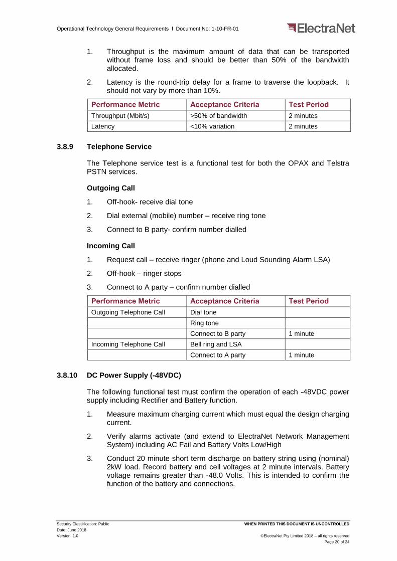
3.8.10 DC Power Supply (-48VDC)
The following functional test must confirm the operation of each -48VDC power supply including Rectifier and Battery function.
1. Measure maximum charging current which must equal the design charging current.
2. Verify alarms activate (and extend to ElectraNet Network Management System) including AC Fail and Battery Volts Low/High
3. Conduct 20 minute short term discharge on battery string using (nominal) 2kW load. Record battery and cell voltages at 2 minute intervals. Battery voltage remains greater than -48.0 Volts. This is intended to confirm the function of the battery and connections.

Operational Technology General Requirements l Document No: 1-10-FR-01
Security Classification: Public WHEN PRINTED THIS DOCUMENT IS UNCONTROLLED
Date: June 2018
Version: 1.0 ©ElectraNet Pty Limited 2018 – all rights reserved
Page 21 of 24
Performance Metric Acceptance Criteria Test Period
Maximum charging current Equals design value 1 minute
Alarms AC Fail, Battery Volts Low/High
Battery discharge test Battery Volts > -48V 20 minutes
3.9 Asset Information Requirements
All OT assets must be identified in SAP and will be provided with a unique Functional Location (FunLoc) and Barcode.
All OT assets must be planned, designed and managed (e.g. configuration, settings, etc.) in ETCDB.
All on-site equipment must be clearly labelled with the equipment's ETCDB Asset Name and the Asset Barcode. For exterior equipment, the self-adhesive Asset Barcodes and referencing the equipment's ETCDB Asset Identification must be placed on an External Asset Barcode plate that must reside in an accessible location within the associated Telecommunications equipment room.
Environmentally exposed labels must be permanent external grade labels that offer very high UV resistance.
Underground cable sheaths (and other underground equipment) must be identified and labelled in all access pits with permanent external grade labels capable of withstanding immersion in standing water.
All equipment must be provided with attendant dedicated operational Firmware / software (e.g. System Licenses, management information base, network management system interfaces, local craft terminal application, remote access application, warranty information, factory inspection test results, commissioning test records and any other documentation (installation, operations and maintenance) pertinent to the equipment provided.

Operational Technology General Requirements l Document No: 1-10-FR-01
Security Classification: Public WHEN PRINTED THIS DOCUMENT IS UNCONTROLLED
Date: June 2018
Version: 1.0 ©ElectraNet Pty Limited 2018 – all rights reserved
Page 22 of 24
Appendices

Operational Technology General Requirements l Document No: 1-10-FR-01
Security Classification: Public WHEN PRINTED THIS DOCUMENT IS UNCONTROLLED
Date: June 2018
Version: 1.0 ©ElectraNet Pty Limited 2018 – all rights reserved
Page 23 of 24
Appendix A Generic Operational Technology Deployment at Substations
Figure A-1 Generic OT Deployment
Wir
ele
ss
Acc
ess
Poi
nt
Secu
rity
P
ane
l
Tele
pho
ny
(A)
Tele
pho
ny
(B)
48V
Po
we
r Sy
ste
m (
B)
PSP
M/P
QM
/TW
FL
IP N
etw
ork
Term
inat
ing
Equ
ipm
ent
(A)
IP S
ervi
ce S
wit
ch (
A)
Fire
wal
l (A
)
Bea
rer
(A)
Be
are
r (B
)
IP N
etw
ork
Term
inat
ing
Equ
ipm
ent
(B)
Cir
cuit
Ter
min
atin
g Eq
uip
men
t (A
)C
ircu
it T
erm
inat
ing
Equ
ipm
ent
(B)
IP S
ervi
ce S
wit
ch (
B)
Site
Serv
er
48V
Po
we
r Sy
ste
m (
A)
SCA
DA
Gat
ew
ay
Fire
wa
ll (B
)
Prot
ecti
on
Set
XC
37
.94
Mu
ltim
ode
Op
tica
l
Pro
tect
ion
Se
t Y
C37
.94
Mu
ltim
od
e O
pti
cal
SCA
DA
(M
ain
)D
NP
/ IP
10
00
BA
SE-S
X
(Gig
E)M
ult
imo
de
Op
tica
l
AEM
O (
Mai
n)
DN
P /
IP1
00
0B
ASE
-SX
(G
igE)
Mu
ltim
od
e O
pti
cal
SCA
DA
(St
and
by)
DN
P /
IP1
00
0B
AS
E-SX
(G
igE)
Mu
ltim
od
e O
pti
cal
Sub
stat
ion
Mgm
t10
00B
ASE-
SX
(Gig
E)M
ult
imo
de
Op
tica
l
AEM
O (
Stan
db
y)D
NP
/ IP
10
00
BA
SE-S
X
(Gig
E)M
ult
imo
de
Op
tica
l
Su
bst
atio
n M
gmt
Bac
kup
(Op
tion
al)
10
00
BA
SE-S
X
(Gig
E)M
ult
imo
de
Op
tica
l
ATA
(A
)A
TA (
B)
Tele
phon
y (M
ain
)T
wis
ted
Pa
irCa
t5E
2W
Lo
op
Tele
ph
on
y (B
acku
p)
Twis
ted
Pair
Cat
5E
2W
Lo
op
Set
X In
terf
ace
Pan
elSe
t Y
In
terf
ace
Pa
ne
l
IDEN
TIFI
ED U
SER
SH
AR
ED A
SSET
INTE
RFA
CE
WO
RK
S