
OPERATIONAL PERFORMANCE OF 2 x 5000 m /day MSF …iwtc.info/2003_pdf/09-3.pdf · OPERATIONAL...
13
Seventh International Water Technology Conference Egypt 1-3 April 2003 OPERATIONAL PERFORMANCE OF 2 x 5000 m 3 /day MSF SIDI KRIR DESALINATION PLANT PART I ENHANCEMENT OF CHEMICAL CLEANING & BRINE HEATER CONDENSATE PROCESS Hassan E. S. Fath* and Mohamed A. Ismail** * Thermal Engineering &Desalination Technology Dept. King Abdul Aziz Univ., Jeddah, Saudi Arabia ** Egyptian Electricity Holding Company (EEHC), Alex., Egypt ABSTRACT This paper discusses effect of the abnormal seawater carbonates concentration at the 2 x 5000 m 3 /day Multi Stage Flash (MSF) Sidi Krir desalination unit’s site and the variation in scale grade in both (i) Brine Heater and (ii) Evaporator Condensers (water boxes). The negative side effects of combining the two heat transfer components in one acid cleaning circuit are discussed and the approach for separating the cleaning circuits of these two heat transfer components is presented. On the other hand, an indirect Brine Heater heating system; using a separate re-boiler is proposed. The technical and economical advantages of these proposals are highlighted. Key Words: Desalination, MSF, Performance, Scale, Chemical / Acid Cleaning. INTRODUCTION Sidi Krir power plant (2 x 325 MWe), located at the Mediterranean Sea (West coast of Alexandria, Egypt) has a 2 x 5000 m 3 /day MSF distillation units of brine re- circulation type. Each unit consists of 17 heat recovery stages and 3 heat rejection stages. Heating steam is delivered from the power plant’s auxiliary boiler of a reduced pressure of 7-8 bars. More plant design specifications are given in Table (1). Being at the south coast of Mediterranean Sea, Sidi Krir MSF desalination units face a relatively higher sea water salinity and abnormal sea water concentration of carbonates. Such special concentration is mainly due to the geological structure of this coast, which is distinctive with high lime sediments, in addition to the minor effect of tidal and civil activities. Similar water analysis could be expected along the south
Transcript of OPERATIONAL PERFORMANCE OF 2 x 5000 m /day MSF …iwtc.info/2003_pdf/09-3.pdf · OPERATIONAL...
Seventh International Water Technology Conference Egypt 1-3 April 2003 ��
���
OPERATIONAL PERFORMANCE OF 2 x 5000 m3/day MSF SIDI KRIR DESALINATION PLANT
PART I ENHANCEMENT OF CHEMICAL CLEANING & BRINE HEATER
CONDENSATE PROCESS
Hassan E. S. Fath* and Mohamed A. Ismail**
* Thermal Engineering &Desalination Technology Dept. King Abdul Aziz Univ., Jeddah, Saudi Arabia
** Egyptian Electricity Holding Company (EEHC), Alex., Egypt ABSTRACT
This paper discusses effect of the abnormal seawater carbonates concentration at the 2
x 5000 m3/day Multi Stage Flash (MSF) Sidi Krir desalination unit’s site and the
variation in scale grade in both (i) Brine Heater and (ii) Evaporator Condensers (water
boxes). The negative side effects of combining the two heat transfer components in
one acid cleaning circuit are discussed and the approach for separating the cleaning
circuits of these two heat transfer components is presented. On the other hand, an
indirect Brine Heater heating system; using a separate re-boiler is proposed. The
technical and economical advantages of these proposals are highlighted.
Key Words: Desalination, MSF, Performance, Scale, Chemical / Acid Cleaning. INTRODUCTION
Sidi Krir power plant (2 x 325 MWe), located at the Mediterranean Sea (West
coast of Alexandria, Egypt) has a 2 x 5000 m3/day MSF distillation units of brine re-
circulation type. Each unit consists of 17 heat recovery stages and 3 heat rejection
stages. Heating steam is delivered from the power plant’s auxiliary boiler of a reduced
pressure of 7-8 bars. More plant design specifications are given in Table (1). Being at
the south coast of Mediterranean Sea, Sidi Krir MSF desalination units face a
relatively higher sea water salinity and abnormal sea water concentration of
carbonates. Such special concentration is mainly due to the geological structure of this
coast, which is distinctive with high lime sediments, in addition to the minor effect of
tidal and civil activities. Similar water analysis could be expected along the south
Seventh International Water Technology Conference Egypt 1-3 April 2003 ��
���
Mediterranean Sea and in plants sites as Al Arish (Egypt) and Zilton and Derna
(Libya). Table (2) shows the differences in concentrations between standard sea water
and measured values at Sidi Krir site. As it known, such water concentration will be a
main cause of scale deposits that significantly influences the unit operational
performance. The intake system of these plants can not be improved (by conventional
pre-treatment processes) and operation staff have to face and deal with this
phenomenon and its side effect. This abnormal seawater concentration shows,
therefore, its negative impact on the unit performance, specially the rate of acid
cleaning required. The first part of this paper discusses effect of such abnormal
seawater carbonates concentration on the plant operation The negative side effects of
combining the two heat transfer components in one acid cleaning circuit are discussed
and the approach for separating the cleaning circuits of these two heat transfer
components is presented.
On the other hand, in Sidi Krir (as most of desalination plants), Brine Heater is
supplied with high quality auxiliary steam from the main power plant circuit. A
conductivity analyzer is installed in the condensate line to guarantee the high quality
condensate return. There is always a possibility of condensate contamination (tubes
leaks) with the malfunction of the analyzer. The operation staff may prefer to dump
the condensate to sea (through a discharge line) in case of any doubts or irregular
performance of the analyzer in order to avoid any disturbances in the power plant
condenser if such condensate in returned back to the main plant condenser. The second
part of this paper proposes, therefore, an indirect Brine Heater heating system; using a
separate re-boiler; is proposed. The technical and economical advantages of these
proposals are highlighted.
I- SCALE DEPOSITS & ACID CLEANING
A- Factor Affecting Scale Deposits
Scale deposits on the heating surfaces represent one of the major problems
facing the operational performance in MSF distillation units. Dissolved salts such as
Calcium Carbonate, Magnesium Chloride, Sodium Chloride and Calcium Sulfate are
common seawater salts of different solubility. Presence of other salts often exerts a
Seventh International Water Technology Conference Egypt 1-3 April 2003 ��
���
strong influence on the solubility. Different factors are considered as a prerequisites
for scale deposit; i) presence of nucleation sites, ii) dissolved solids reaches its super
saturation condition, and iii) reasonable retention time of solution inside the unit. Scale
formation is also influenced by solution temperature, pH and fluid velocity (flow
turbulence). Smooth heat transfer surface minimizes the presence of nucleation sites
for scale deposits and crystallization. Higher flow velocity and enough turbulence (and
less presence of stagnant pockets) also reduces scale deposition.
As saline water temperature increase, the solubility of some salts is lowered; hence
super saturation is reached and is immediately followed by salt deposits. Solubility –
temperature relationship is considered a prim controlling factor for creating super
saturation and scale deposit conditions. It has been explained by the inverted solubility
curve of the common dissolved solids in the saline water. Generally speaking, scale
formation occurs more quickly in the tube sections of the high temperature such as
Brine Heater and high temperature stages of the evaporator. Decreasing the system
Top Brine Temperature (TBT) could improve the scale deposit situation, however, low
TBT negatively influence the system performance and productivity (reduction in the
flashing range). Designers have to strike the correct TBT that can technically and
economically balance scale deposits, operational performance, capital and running
costs.
The formation of alkaline scale (calcium carbonate and magnesium hydroxide) is
considered to be a natural phenomenon in sea water distillation plants. High alkalinity
(carbonate, bicarbonate and hydroxides) was recorded with such abnormal
concentration along the Sidi Krir site coast, as indicated in Table (2). Six kg per cubic
meter of hardness (expressed as calcium carbonate) require softening chemicals of
almost the same order. For a 2 x 5000 m3/day Sidi Krir (and large capacity) plant(s)
this would consume several tons of softening chemicals per day and the cost of pre
treatment chemicals and softening will be quite considerable and can not be
economically justified. In addition, the pretreatment using Nano filtration has not, yet,
proved technically and economically to be the alternative solution.
Seventh International Water Technology Conference Egypt 1-3 April 2003 ��
���
Another factor influencing the scale deposit is the solution pH. The solubility of
calcium carbonate is determined by the solubility product of calcium and carbonate
ions; i.e. c Ca x c CO3. Increasing the solution temperature deposits Calcium
Carbonate (CaCO3) from its saturated solution). This situation occurs even if no
carbon dioxide is lost and no evaporation takes place. In practice, however, the heating
of saline water leads to loss of carbon dioxide from the water which in addition to the
progressive increase in concentration (due to evaporation) enhances calcium carbonate
deposits.
Scale formation indications are usually observed and monitored by; (i) An increase in
brine heater pressure and temperature, (ii) drop in TBT (increase in Brine Heater
terminal temperature difference), (iii) Loss of distillate production (the rated distillate
output can no longer be maintained under the same steam consumption), (iv) reduction
in performance ratio (PR). Different techniques are implemented for scale prevention
(or minimization) of Sidi Krir and most of desalination plants including; i) Design the
unit temperatures and brine concentrations with minimum opportunity to form salts
super-saturation solution before it leaves the unit, ii) partial removal of salts causing
scale-formation from saline feed water (intake system) using softening (Ultra and/or
Nano Filtration), specially for small units iii) Chemical additives (e.g. acids) which
causes a decrease in pH, iv) Anti scalent additives that retards (or delays) scale
deposition on heating surface (2.g. polyphosphate, Belgard EV-2000, …etc), v)
Mechanical cleaning (e.g. spongy balls, …etc) and Chemical (Acid) cleaning to
remove precipitated scale during operation., and finally, vi) Scheduled acid cleaning
B- Acid Cleaning
Scheduled acid cleaning process is used to remove accumulated alkaline scale
of calcium carbonate (Ca CO3), and magnesium hydroxide (Mg (OH)2) during a
specified period of operation. This process is accomplished by circulating a diluted
acid solution through the loop to be cleaned. A good monitoring and operation of the
scheduled acid cleaning is necessary to maintain a good plant performance and at the
same time protect the heat transfer tubes from corrosion. As indicated before, scale
formation would be more apparent in the brine heater (and the nearer stages of the

Seventh International Water Technology Conference Egypt 1-3 April 2003 ��
���
evaporator condenser tubes) due to the higher saline water temperature, leading to
reaching super saturation conditions. In addition, the danger of hard scale deposit may
also be possible in such high temperature zones that increase the hardship of scale
removal (In fact, inspection staff usually notice the presence of such high grade –hard-
scale inside the brine heater tubes). In addition, some brine heater tubes blocking is
observed, while the low temperature condenser tubes (and water boxes) are clean).
These factors should be taken into consideration when acid cleaning process is
applied.
A usual plant practice is to test a selective sample in the plant laboratory, in order to
detect the minimum active acid concentration that can dissolve the scale (in an
acceptable cleaning time) with tube corrosion protection. Table (3) shows a typical
acid cleaning test results. The table indicates that the acceptable acid concentration
Table (4) summarizes the acid cleaning process specification, while Table (5)
summarizes the plant typical acid cleaning process specifications and procedure.
C- Enhancing Acid Cleaning Process
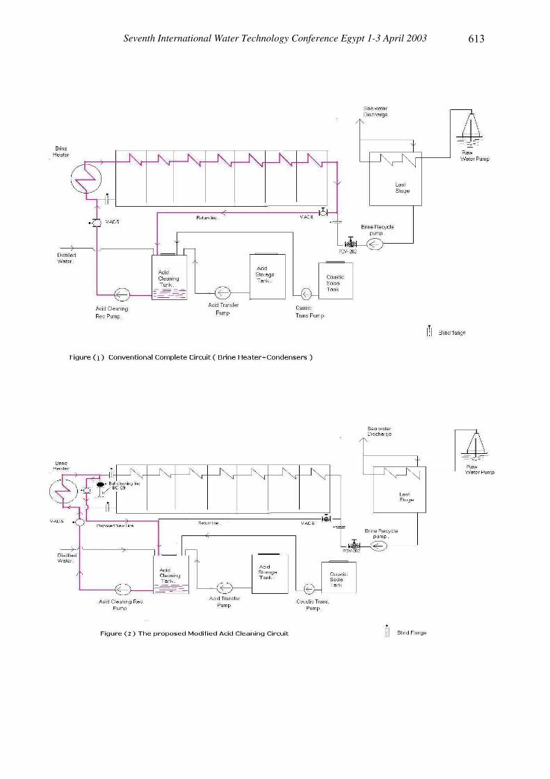
In most of desalination plants, design of acid cleaning circuits combine both (i)
brine heater and (ii) evaporator condensers tubes in one integrated circuit. Figure (1)
shows the conventional acid cleaning circuit, which incorporates both brine heater and
condensers tubes.
Inserting the two heat transfer components in one acid cleaning circuit (same acid
dilution and cleaning period) may lead to the deterioration of condenser tubes material
which are usually made of lower grade alloy than Brine Heater tubes. Exposing the
lower grades (and relatively clean condensers tubes) to the same cleaning process and
rates as the (higher grade alloys and highly scaled) brine heater tubes, cause a higher
chemical stress on condensers tubes, where a considerable copper ions (Cu++) was
recorder (> 5 ppm) although inhibitor is normally added.
A modification in acid cleaning circuit is therefore needed to prevent such chemical
stress and maintain high unit performance (performance ratio - PR) and short unit
outage (availability factor - AF). The proposed new approach separates the cleaning

Seventh International Water Technology Conference Egypt 1-3 April 2003 ��
���
circuits of the brine heater and evaporator components as shown in Figure (2). The
modification of the original system (compare Figures (1) & (2)) consists only of
adding a Tee connection at the ball cleaning line. A few meters (2 m -10 m) 3.0 inches
pipe line connects the Tee to the acid cleaning tank with an isolation valve. A blind
flange will be installed at the line connecting the B. H. to the evaporator to isolate the
B. H. from the evaporator. In this case we can have two circuits operates separately. In
case B.H. is only needed to be cleaned, acid flow out from the B.H. will be forced to
flow through the Tee to the acid cleaning tang (the blind flange will block the acid
flow to the evaporator), as shown in Figure (2). In case both B. H. and evaporator are
to be cleaned, the isolation valve is closed the flow is forced to go as normal to the
evaporator as shown in Figure (1).
The effect of the proposed approach in enhancing the acid cleaning process, as well as
its technical and economical advantages could be obtained from Table (6). The
advantages includes; (i) Low chemical consumption, (ii) Shorter outage time, which
increases the unit availability and, therefore, production, (iii) protection of water boxes
and condensers tubes against chemical stresses, and (iv) improving the performance of
ball cleaning system. All these factors lead ultimately to lower water production cost.
II- HEATING STEAM TO BRINE HEATER
As previously indicated, the operation staff may prefer to dump the condensate to sea
(through a discharge line) in case of any doubts or irregular performance of the
analyzer in order to avoid any disturbances in the condenser if such condensate in
returned back to the main plant condenser. In the last year, condensate dumping took
place in about 70 % of the plant-operating time. Loss of Brine Heater condensate
(600 m3/day) represents about (3000 $ of water + 1000 $ of heat = 4000 $) per day; i.e.
1.0 $ million per year.
In order to prevent or reduce such water and heat cost loss, an indirect Brine Heater
heating steam system; using a separate re-boiler, is proposed. The proposed system
would provide the B.H. with the required steam where its condensate is contained in a
closed loop, separate from the main power plant steam. As conventional re-boilers

Seventh International Water Technology Conference Egypt 1-3 April 2003 ��
���
used in the plant, auxiliary steam from the power plant will be used as a source of heat
for the re-boiler. Figure (3) illustrates typical re-boilers used in Sidi Krir plant to
provide 5.0 bars, 160°C saturated steam for different processes as (i) Mazout storage
and transfer heaters, (ii) burners fuel heaters, and (iii) heat tracing piping steam.
Figure (4) illustrates the proposed re-boiler circuit for B. H. steam supply. For new
plants, this circuit could be replaced by the proposed separate re-boilers system, as
shown in Figure (5) or integrated with the re-boilers for other plant processes. Due to
the location limitation in Sidi Krir, the circuit would be built separately and as near to
the desalination units as possible. Similar to the other re-boilers circuits, the system
will be designed to provide the B. H. with the required saturated steam at 7.0 bars,
205°C and 600 m3/day. Condensate from B. H. would be collected in the re-boiler
condensate collection tank and (or directly) forwarded to the re-boiler feed tank by the
re-boiler condensate transfer pump(s) (In the conventional re-boiler system, the unit
condensate transfer pumps supply any shortfall in condensate tank requirements, in
order to maintain the condensate level, through a level control system). Condensate is
then pumped back to the re-boiler. The same auxiliary steam at 15 bar (g) and 275°C is
supplied with the required flow rate to the new re-boiler as its heat source. The steam
is then de-superheated to 213°C by a desuper heating system before it enters the tube
side of the re-boiler. The auxiliary steam is condensed and the condensate is collected
in the drain tank, Figure (5), then transferred to the main circuit by pressurizing the
drain tank with the auxiliary steam (from the auxiliary steam header).
Table (6) summarizes the expected capital cost of the re-boiler system, while Table (7)
summarizes the running cost and the pay back period of the newly proposed system.
From these tables, it seems that the proposed system is economically feasible and its
pay back period is only 7-8 months. This adds to the technical advantages of the
proposed B. H. heating system of either (i) protecting the main power plant water
quality or (ii) water and energy loss of dumping B.H condensate to the sea.
REFERENCES
1- IDA World Wide Desalting plants Inventory Report No. 10 (2000).

Seventh International Water Technology Conference Egypt 1-3 April 2003 ��
��
2- Hassan Fath “Desalination Technology”, Chapter 6, Al-Dar Al-Jameiah, Alex.
(2001).
3- F. Belan “Water Treatment” MIR Publisher, Moscow (1979).
4- W. F. Langeleir “Mechnism and Control of Scale Formation in Seawater” Water
Works Assoc. (1954).
5- C. W. L. Badger “Conventional Methods of Scale Prevention” Office of Saline
Water Report, No. 25, US-Washington (1959).
6- EEHC Records.
7- Hassan Fath “Long Term Analysis & Effect of Acid Cleaning Tests on the
Performance of MSF Desalination Units”, Proceedings of the Fourth Int. Water
Technology Conf., IWTC-99, March (1999).
Table (1) Technical Specifications of Sidi Krir 2 x 5000 m3/day MSF Desalination Plant
Parameter Value (Remark) No. of Units 2 Unit Capacity 5000 m3/day No. of Stages 20 (17 + 3) Designed PR 8 kg (PW) / kg (steam) TBT 110°C Seawater Temp. 27°C Heating Steam Temp. 117°C Cooling Water Flow Rate 1570 m3/hr Brine Recirculation Flow Rate 1850 m3/hr Seawater Concentration 43900 ppm Brine Concentration 63000 ppm PW Quality 25 ppm Method of Scale Control High Temp. Additives (Belgard EV 2000) Tube Sheet Material (BH + Condensers)
90 / 10 Cooper Nickel
Condensers Tubes 90 / 10 Cooper Nickel Brine Heater Tubes 70 / 30 Cooper Nickel Water Box (BH + Condensers) 90 / 10 Cooper Nickel
Seventh International Water Technology Conference Egypt 1-3 April 2003 ��
�
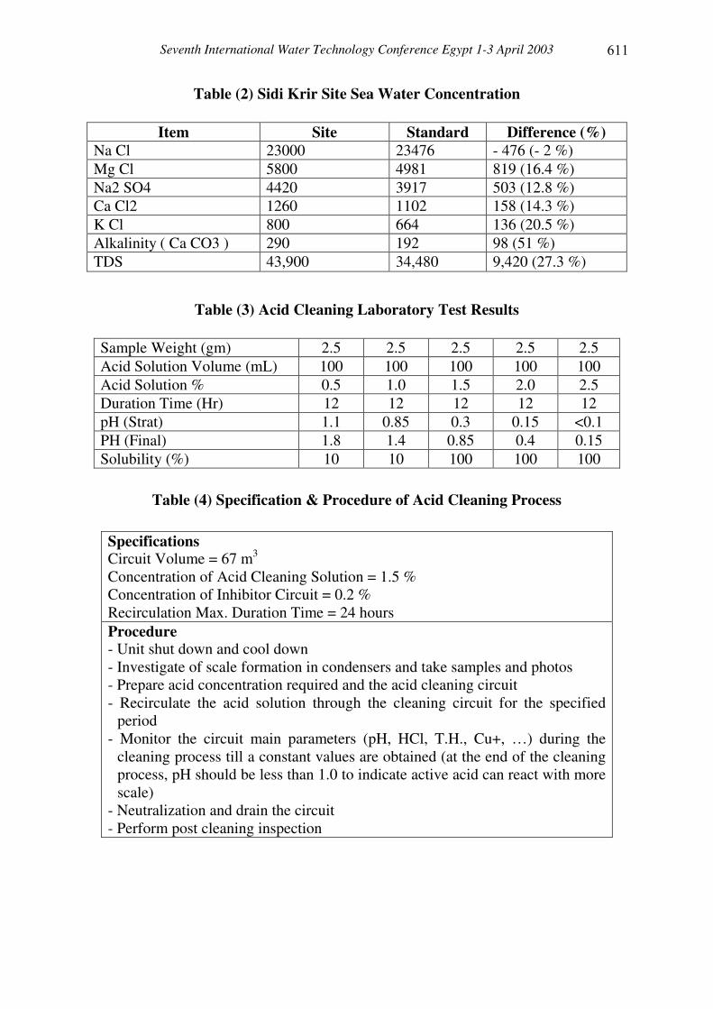
Table (2) Sidi Krir Site Sea Water Concentration
Item Site Standard Difference (%) Na Cl 23000 23476 - 476 (- 2 %) Mg Cl 5800 4981 819 (16.4 %) Na2 SO4 4420 3917 503 (12.8 %) Ca Cl2 1260 1102 158 (14.3 %) K Cl 800 664 136 (20.5 %) Alkalinity ( Ca CO3 ) 290 192 98 (51 %) TDS 43,900 34,480 9,420 (27.3 %)
Table (3) Acid Cleaning Laboratory Test Results
Sample Weight (gm) 2.5 2.5 2.5 2.5 2.5 Acid Solution Volume (mL) 100 100 100 100 100 Acid Solution % 0.5 1.0 1.5 2.0 2.5 Duration Time (Hr) 12 12 12 12 12 pH (Strat) 1.1 0.85 0.3 0.15 <0.1 PH (Final) 1.8 1.4 0.85 0.4 0.15 Solubility (%) 10 10 100 100 100
Table (4) Specification & Procedure of Acid Cleaning Process�
Specifications Circuit Volume = 67 m3 Concentration of Acid Cleaning Solution = 1.5 % Concentration of Inhibitor Circuit = 0.2 % Recirculation Max. Duration Time = 24 hours Procedure - Unit shut down and cool down - Investigate of scale formation in condensers and take samples and photos - Prepare acid concentration required and the acid cleaning circuit - Recirculate the acid solution through the cleaning circuit for the specified
period - Monitor the circuit main parameters (pH, HCl, T.H., Cu+, …) during the
cleaning process till a constant values are obtained (at the end of the cleaning process, pH should be less than 1.0 to indicate active acid can react with more scale)
- Neutralization and drain the circuit - Perform post cleaning inspection

Seventh International Water Technology Conference Egypt 1-3 April 2003 ��
�
Table (5) Comparison Between Present and Modified Acid Cleaning Circuits
Item Present Modified Circuit Volume (m3) 67 8 Acid Consumption (Liters) (37 % Concentration)
3 000
400
Inhibitor Consumption (Liter) 150 20 Neutralization Caustic Soda (Lit) (50 % Concentration)
1500
200
Outage Time (Days) 3 1 Chemicals Cost (USD), (1) 1,250 220 Cost of PW Loss During Cleaning (USD), (2)
18,000 6000
Total Cost (1) + (2) 19,250 6220
Table (6) Estimating Capital Cost of Sidi Krir Reboiler System
Item Cost ($) Aux. Reboiler Heater (A,B) Feed + Condensate Pumps (A,B) Drain + Feed Tanks Furnishing Pipes + Insulation Furnishing Equipment
365,859 35,220 123,562 20,000 61,000
Total 605,641 Pay Back Period = Total Cost / Annual saving = 605,641 / 1000,000
7 – 8 months
Table(7) Reboiler System Running Cost
Item Cost ($) Pumps Power (Feed =24 kW, Condensate=10 kW) = (24+10) kW x 24 hrs/ day x 365 day/year x 0.02 $./kWhrs) Capital Installment (Annuity) = 605,641 [ (1+.06)25 ] / 25
5,957 77,695
Total 83,652
Seventh International Water Technology Conference Egypt 1-3 April 2003 ��
��

Seventh International Water Technology Conference Egypt 1-3 April 2003 ��
��

Seventh International Water Technology Conference Egypt 1-3 April 2003 ��
��

![OCB EBOLA REVIEW - MSF Intersectional Evaluation Groupcdn.evaluation.msf.org/.../ocb_ebola_review_medop_final_2.pdf · OCB EBOLA REVIEW Part 1: Medico-operational [March 2016] This](https://static.fdocuments.us/doc/165x107/5b05e1847f8b9ad1768c04dc/ocb-ebola-review-msf-intersectional-evaluation-ebola-review-part-1-medico-operational.jpg)