Operational Amplifiers
37
introduction Operational Amplifiers
-
Upload
sabyasachi-bhowmick -
Category
Engineering
-
view
188 -
download
6
description
This Presentation provides the full details of Operational Amplifiers, It`s types , construction..everything.
Transcript of Operational Amplifiers

introduction
Operational Amplifiers

introduction
Introduction The operational amplifier or op-amp is a circuit of components integrated into one chip.
A typical op-amp is powered by two dc voltages and has an inverting(-) and a non-inverting input (+) and an output.
An op amp is an electronic device which provides a voltage output based on the voltage input

introduction
Basic op-amp
Op-amp has two inputs that connect to two terminals and one output

introduction
Operational Amplifiers
Five important pins
2 – The inverting input 3 – The non-inverting input 6 – The output 4 – The negative power supply V- (-Vcc) 7 – The positive power supply V+ (+Vcc)
introduction
Operational Amplifiers
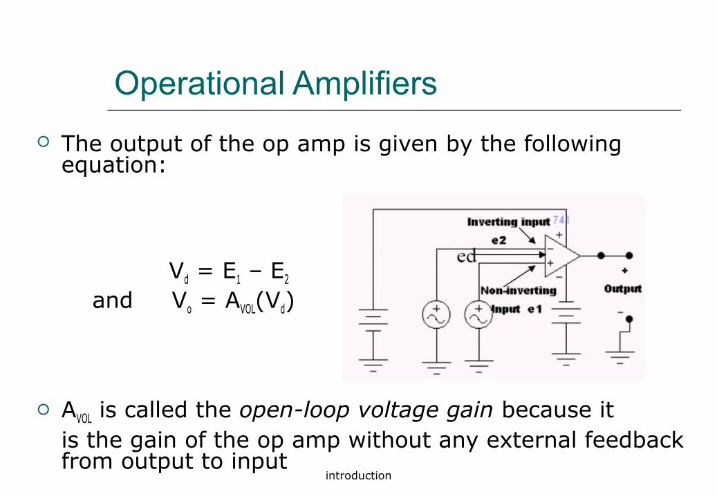
The output of the op amp is given by the following equation:
Vd = E1 – E2
and Vo = AVOL(Vd)
AVOL is called the open-loop voltage gain because it is the gain of the op amp without any external feedback from output to input
introduction
Operational Amplifiers
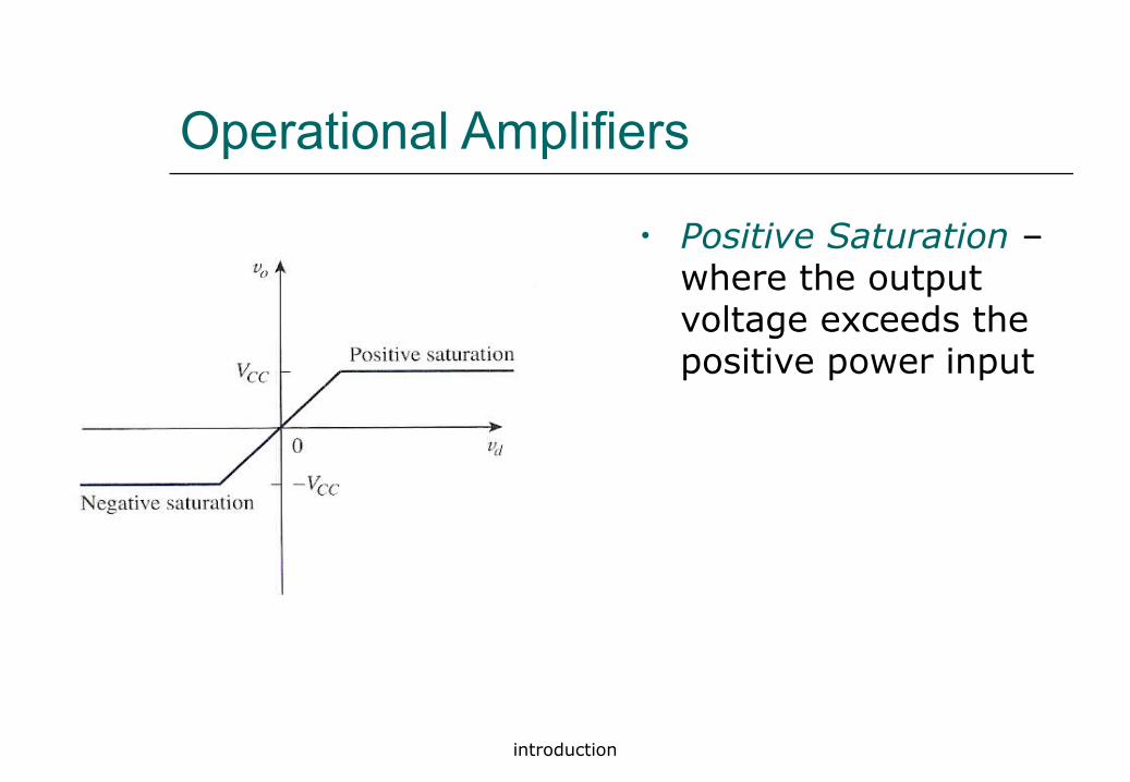
• Positive Saturation – where the output voltage exceeds the positive power input

introduction
Operational Amplifiers
• Linear Region – where the output voltage is linear based on A (gain)

introduction
Operational Amplifiers
• Negative Saturation – where the output voltage would be less than the negative power input

introduction
Operational Amplifiers
introduction
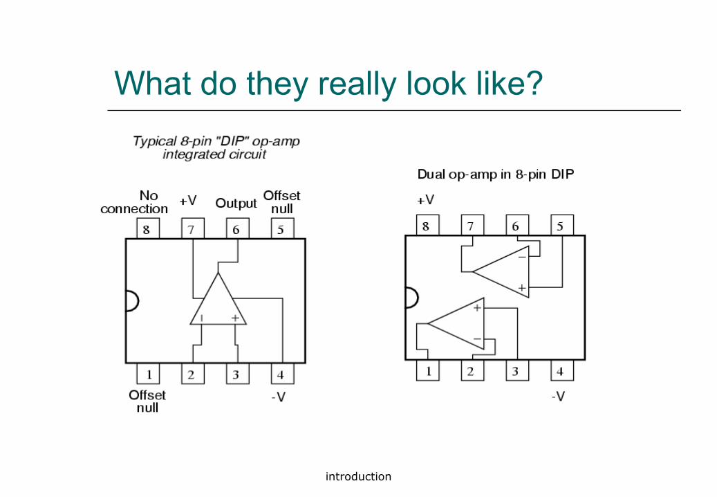
What do they really look like?

introduction
IC Circuit

introduction
Operational Amplifiers
introduction
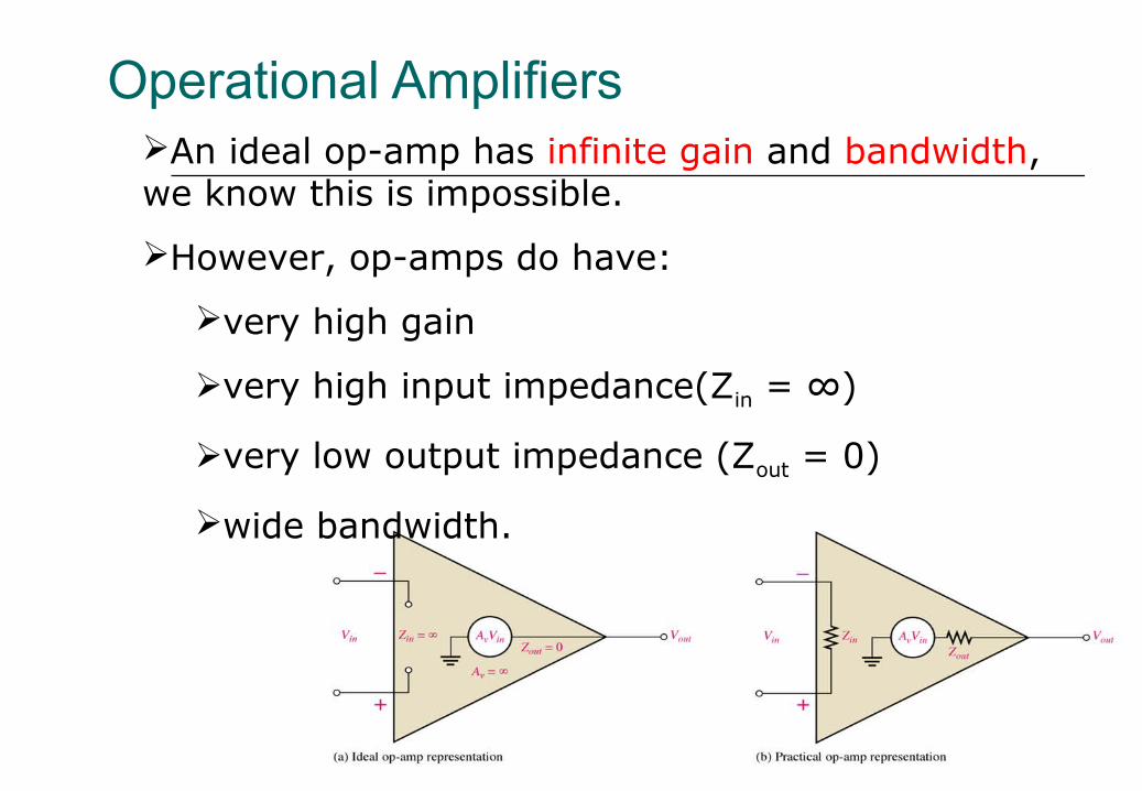
Operational AmplifiersAn ideal op-amp has infinite gain and bandwidth, we know this is impossible.
However, op-amps do have:
very high gain
very high input impedance(Zin = ∞)
very low output impedance (Zout = 0)
wide bandwidth.

application
Application in op-amp
There are 2 types of application in op-amp Linear application Non-linear application
Linear application is where the op-amp operate in linear region: Assumptions in linear application:
Input current, Ii = 0 Input voltage: V+=V-
Feedback at the inverting input

application
Non-linear application is where the op-amp operate in non-linear region
By comparing these two input voltages: positive input voltages, V+ and negative input voltage, V- where:
VO = VCC if V+ > V-
VO = -VEE if V+ < V-
Input current, Ii = 0
Application in op-amp

application
Applications of op-amp
Comparator Inverter Audio amplifier Difference Amplifier Filter Summing Amplifier

application
Inverting Amplifier Non-Inverting Amplifier Summing Amplifier Unity Follower Difference Amplifier Integrators Differentiators
Op-amp Circuit Application
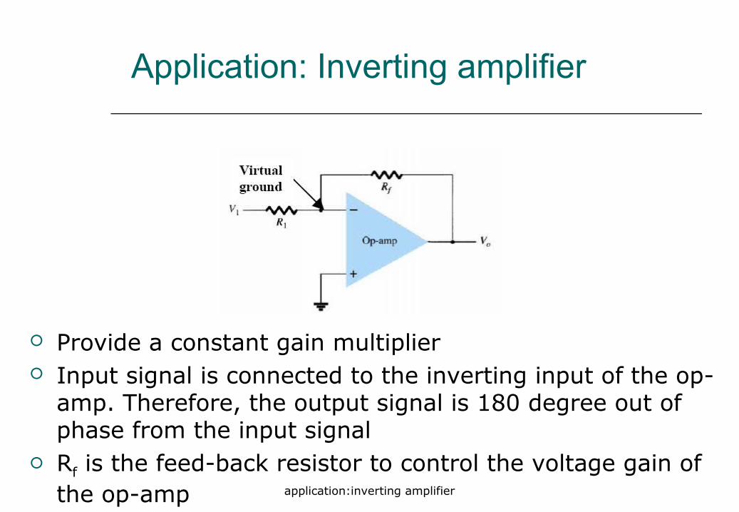
application:inverting amplifier
Application: Inverting amplifier
Provide a constant gain multiplier Input signal is connected to the inverting input of the op-
amp. Therefore, the output signal is 180 degree out of phase from the input signal
Rf is the feed-back resistor to control the voltage gain of the op-amp

application:inverting amplifier
Summary of op-amp behavior
Vo = A(V+ - V−)
Vo/A = V+ - V−
Let A infinity
then,
V+ - V− 0

application:inverting amplifier
V+ = V−
I+ = I − = 0
Seems strange, but the input terminals to anop-amp act as a short and open at the same time
Summary of op-amp behavior

application:inverting amplifier
To analyze an op-amp circuit for linear operation
•Write node equations at + and - terminals
(Ii=I+ = I- = 0)
•Set V+ = V-
•Solve for Vo

application:inverting amplifier
Analysis of inverting amplifier
I1
If
Ii
€
V + = 0 Ii = 0
I1 = I f + Ii
Vs −V−
R1
= V − −Vo
Rf
V− =V + = 0
Vo
Vs
= −Rf
R1
Vo = −Rf
R1
Vs

application:non-inverting amplifier
Application:Non-inverting amplifier
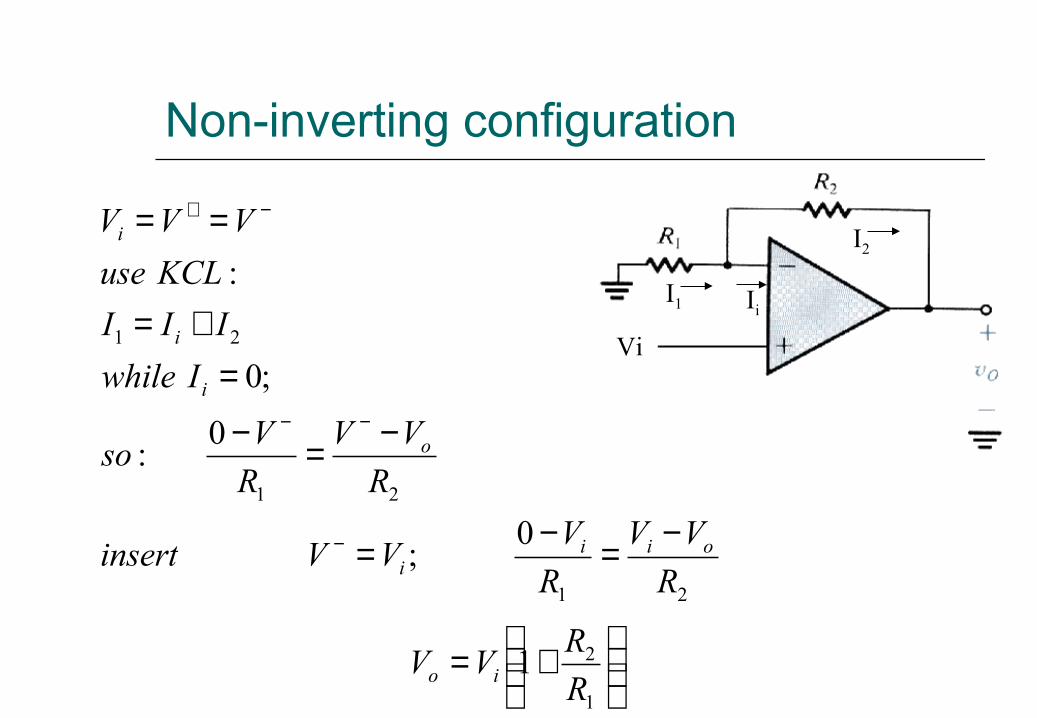
Non-inverting configuration
+=
−=−=
−=−
=+=
==
−
−−
−+
1
2
21
21
21
1
0;
0:
;0
:
R
RVV
R
VV
R
VVVinsert
R
VV
R
Vso
Iwhile
III
KCLuse
VVV
io
oiii
o
i
i
i
Vi
I1
I2
Ii

application:summing amplifier
Application: Summing amplifier
Virtual-ground equivalent circuit.
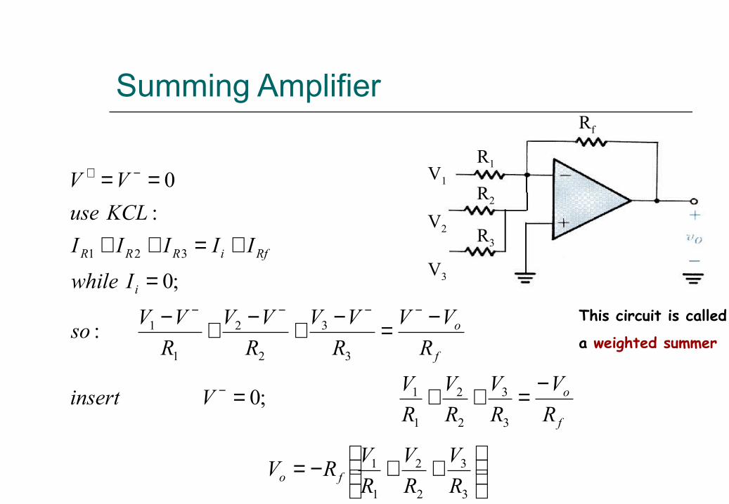
Summing Amplifier
V1
V2
V3
R1
R2
R3
Rf
This circuit is called
a weighted summer
++−=
−=++=
−=−+−+−
=
+=++
==
−
−−−−
−+
3
3
2
2
1
1
3
3
2
2
1
1
3
3
2
2
1
1
321
;0
:
;0
:
0
R
V
R
V
R
VRV
R
V
R
V
R
V
R
VVinsert
R
VV
R
VV
R
VV
R
VVso
Iwhile
IIIII
KCLuse
VV
fo
f
o
f
o
i
RfiRRR
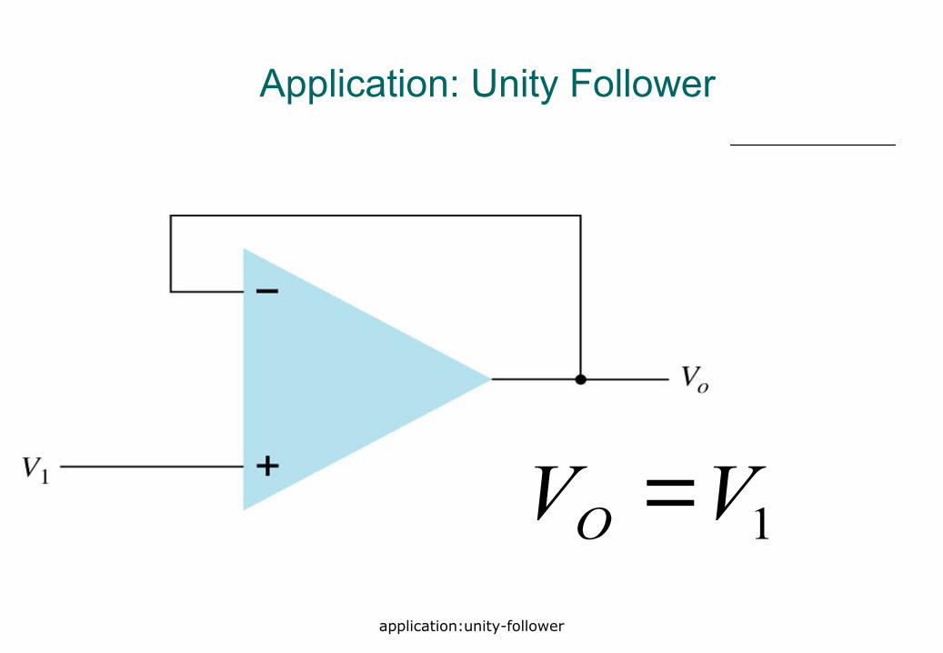
application:unity-follower
Application: Unity Follower
1VVO =

application:difference amplifier
Application: Difference amplifier
)( 212
4 VVR
RVO −=
43
21
RR
RR
==

application:instrumentation amplifier
Application: Instrumentation Amplifier
2RBuffer
2R
1R
1R
AR
BR
AR
Difference amplifier
( )121
2 21 VV
R
R
R
RV
B
AO −
+=
2R

application:integrator
Application: Integrator
Feedback component = capacitor : Integrator
I IC
∫−=
+=
+=
dttvRC
tv
dt
tdvC
R
tv
III
io
i
Ci
)(1
)(
)(0
)( 0
sC
1
Cj
1X
:impedancecetanCapaci
C =ω
=
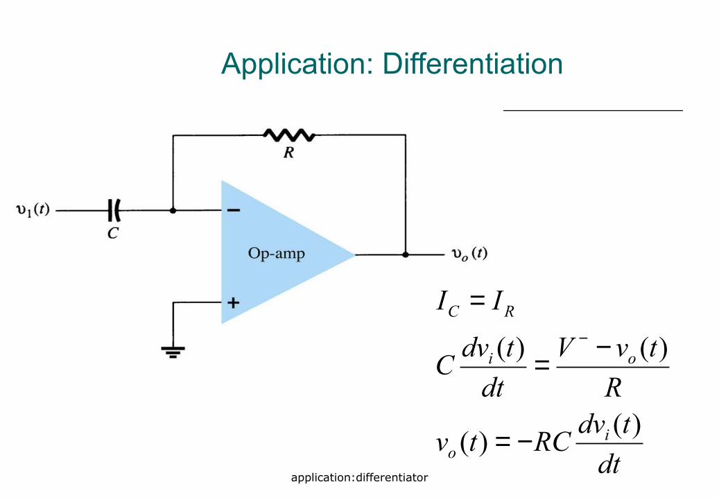
application:differentiator
Application: Differentiation
dt
tdvRCtv
R
tvV
dt
tdvC
II
io
oi
RC
)()(
)()(
−=
−=
=−

exercise
Exercise 1
Find VO?

exercise
Exercise 2
Find V2 and V3?

exercise
Exercise 3
Find VO?

exercise
Exercise 4
Find VO?

non-linear application
Non-linear application is where the op-amp operate in non-linear region
By comparing these two input voltages: positive input voltages, V+ and negative input voltage, V- where:
VO = VCC if V+ > V-
VO = -VCC if V+ < V-
Input current, Ii = 0
Recall: Non-linear application in op-amp

non-linear application:comparator
Non-linear application: Comparator