OPERATION MANUAL - Westermans International Ltd 450 550 dw manual.pdf · OPERATION MANUAL ....
40
OPERATION MANUAL Pulsed-Arc-Welding Units HighPULSE 450 and 550 DW MERKLE Schweißanlagen-Technik GmbH, Industriestr. 3 D-89359 Koetz, Germany Tel.: +49-8221-915-0, Fax: +49-8221-915-40, e-mail: [email protected], www.merkle.de
Transcript of OPERATION MANUAL - Westermans International Ltd 450 550 dw manual.pdf · OPERATION MANUAL ....

OPERATION MANUAL
Pulsed-Arc-Welding Units HighPULSE 450 and 550 DW
MERKLE Schweißanlagen-Technik GmbH, Industriestr. 3 D-89359 Koetz, Germany
Tel.: +49-8221-915-0, Fax: +49-8221-915-40, e-mail: [email protected], www.merkle.de

1

directory page
1 Security indications before introduction 4
2 Accident prevention regulations 4
Safety instructions 4
3 Duty cycle 5
4 Instructions to avoid interferences due to electromagnetic influences EMC 6
5 Technical Data: 7
Wire feeder model DV-31 8
6 Start-up Procedure 9
Machine Installation/Connection to the Mains 9 Wire Feed Unit
it
9 Connection to Gas and the regulation of Gas supply. 10 Installation of the Wire Reel. 10 Installation of the Earth cable 10 Transport 10
7 General Details of the HighPULSE 450/550 DW 10
HighPULSE 450/550 DW Power Supply 11 Ventilation Control 11 Water cooling system 11 Wire Feed Un 11 Electronics 11 TEDAC-System 11 Interpulse-welding 12
8 Front Panel 13
Front Panel and Display Guide 13 Front Panel and Display Guide 14 Wire Feed Unit Display Guide 14
9 Standard functions 14
Switching the machine on 14 Choosing a Process 14
9.1.1 MIG/MAG- und Pulse-Arc Welding Programs 14 9.1.2 Interpulse Welding 15 9.1.3 MMA Welding 15 9.1.4 TIG Welding (Option) 16
2

Operation Modes 16 9.1.5 2-Stroke-Operation 16 9.1.6 4-Stroke-Operation 16 9.1.7 4-Stroke-Operation with selected program 16 9.1.8 The programming of Start Current, Down slope current/Time 16 9.1.9 Safety Cut Off Switch 17
Digital Display Panel 17 Wire feed only Buttons 17 Gas Test 17 Selecting the Current control 18
9.1.10 Potentiometer 18 9.1.11 Wire Feed Unit Potentiometer 18 9.1.12 TEDAC 18 9.1.13 JOB-Functions 18
10 Maintenance 19
11 Cleaning 19
12 Maintenance Inspection 19
13 Problem Solving 20
14 Aluminium Welding 23
15 Wire Feed Unit DV-31 25
16 Torches and Spare Parts 27
17 Wire diagrams 30
18 EU-Conformity Attestation HighPULSE 450 DW 37
19 EU-Conformity Attestation HighPULSE 550 DW 38
3

1 Security indications before introduction The unit device is built after the recognized standards. Safe works are nevertheless only possible if you read the operating instructions and the safety regulations contained in it entirely and obey strictly. Install using the trained staff from our establishments or appointed dealers. 2 Accident prevention regulations The following accident prevention regulation is applied for pulse arc welding unit, model PU 400 DW and PU 520 DW.
BGV D1 (earlier VBG 15) * Welding, cutting and allied processes. A copy of this regulation should be readily accessible in every welding shop. The stipulations of this regulation are to be observed in the interests of safe and correct welding operation. * Available from the trade association responsible or Carl Heymanns-Verlag, Luxemburger Strasse 449, 50939 Cologne.
Safety instructions This unit is manufactured according to the requirements and stipulations of EN 60974.1 / VDE 0544 part 1. BGV D1 (earlier VBG 15) of the trade association for precision engineering and electrical engineering are as well valid.
1) In case of an accident, the cutting unit must be disconnected from the mains immediately. 2) If electrical contact voltages arise, switch off the unit immediately, disconnect it from the mains
and proceed to inspection by a qualified electrician or by our Service Department. 3) Before opening the unit, disconnect it from the mains supply. 4) Repair work may only be carried out by a skilled electrician or by our Service Department. 5) Before the unit is put to operation, check it visually, as well as the torch and all cables and
connectors regarding possible external damages. 6) Personal protective equipment in accordance with DIN EN 175, DIN EN 379 and DIN EN 169.
During the work, the welder’s body must be completely protected against radiation and burns by means of protective clothing and face protection. Long gloves, aprons and welding shields with welding filters conforming to DIN EN 470-1 and BGR 189 must be worn. Synthetic clothing are excluded. Shoes must be closed, not opened (due to spatters). If necessary, protective headwear must be worn (e.g. for overhead welding). If cover glasses are used, these must be in accordance with the norms specified above. As additional protection for the eyes against UV radiation, safety goggles with side shields and corresponding face protection in accordance with BGR 192 and BGI 553 must be worn. Accident prevention regulation BGV D1 § 27 stipulates that it is the responsibility of the employer to provide suitable personal protective equipment, while § 28 stipulates that it is the responsibility of the insured to wear suitable clothing.
4

7) Protection when welding under increased electrical risks Welding rectifiers and welding power sources which can optionally be used for either direct or alternating current must be marked "S" in accordance with EN 60974-1 and BGI 534. Use insulating materials to protect you against contact with electrically conductive parts and damp floors. Wear dry, undamaged work clothing, long gloves and footwear with rubber soles. Ventilate rooms, install extraction systems if required, and wear respiratory protective equipment if necessary (see Procedural instructions BGV D1 § 27 and BGI 533, Section 5).
8) In order to prevent stray currents and the effects thereof (e.g. destruction of electrical protective
ground conductors), the welding return cable (workpiece cable) must be connected directly to the workpiece to be welded or to the table (e.g. welding table, grid-type welding table, workbench) supporting the workpiece (see BGV D1 § 20). When installing the ground connection, assure that there is a good electrical contact (remove rust, paint, etc.).
9) During welding pauses, the welding torch is to be laid down on an insulated surface or hung up in
such a way that it is not in contact with the workpiece and its support connected to the welding power source (see § 20 BGV D1). In the case of longer work pauses, the welding unit must be switched off and the gas cylinder valve must be closed.
10) The shielding gas cylinder must always be protected against tumbling downing using a safety
chain. 11) Under no circumstances the unit may be put into operation while it is opened
(e.g. for repair work). Apart from the safety regulations, sufficient cooling of the electrical components provided by the fan cannot be guaranteed.
12) In accordance with BGV D1 § 5, people in the vicinity of the arc must also be informed of the
hazards and protected against them. Safety partitions (“welding safety curtains”) must be erected in accordance with DIN EN 1598.
14) No welding work may be carried out on containers in which gases, fuels, mineral oils or similar substances have been stored even if they have been empty for a long time (risk of explosion). See § 31 of accident prevention regulation BGV D1.
15) Welds which will be subjected to high loads and which need to meet specific safety requirements
may only be carried out by specially trained and qualified welders. 15) Never bring the torch close to your face. 16) In areas at particularly high risk of fire, the welder must obtain a welding permit and have this on
his person throughout the duration of the welding work. On completion of welding, a fire-guard must be delegated to ensure fire protection.
17) Ventilation measures must be applied in accordance with BGI 553, Section 9. 18) The hazard to eyesight must be indicated by means of a sign at the work site "CAUTION! Do not
look into the arc!". 3 Duty cycle The duty cylce measurings have been carried out in accordance with EN 60974-1 / VDE 0544 part 1 (10 min working period). 60% duty cycle means:
5

After a 6 min. welding period a 4 min welding pause must be respected. The electrical components are thermally protected against overheating. 4 Instructions to avoid interferences due to electromagnetic influences EMC The welding unit has been manufactured in accordance with the requirements of guideline EN 60974-10 / VDE 0544-part 10 regarding electromagnetic compatibility. It is nonetheless the responsibility of the user to ensure that the welding equipment is installed and operated in accordance with the manufacturer’s instructions. If electromagnetic interference is detected, it is the responsibility of the user of the welding equipment to find a solution with the technical assistance of the manufacturer. In some cases, it may be sufficient simply to ground the welding current circuit. In other cases, it may be necessary to build a complete shield for the welding power source and workpiece using the input filters. In all cases, electromagnetic interference must be reduced to avoid any possible malfunctions. Note: For safety reasons, the welding current circuit may or may not be grounded. No modifications may be made to the grounding without the approval of an expert who is able to determine whether the changes might increase the risk of accidents, e.g. by allowing parallel welding current return paths which could destroy the ground conductors of other equipment. Further instructions are contained in TEC 974-XX "Arc welding equipment – installation and use". a) Evaluation of the installation site
Before installing the welding equipment, the user must evaluate potential electromagnetic problems in the vicinity. The following must be taken into consideration:
Other power cables, control cables, signal and telecommunication cables above, below and next to the welding equipment
Radio and television transmitters and receivers Computers and other control devices The health of people in the vicinity, e.g. use of heart pacemaker and hearing aids Calibration and measuring equipment Interference immunity of other devices in the vicinity. The user must ensure the electromagnetic
compatibility of other devices used in the vicinity. This may require additional safety measures. b) Procedures to reduce emitted interference 1) Mains supply
Welding equipment is to be connected to the mains in compliance with the recommendations of the manufacturer. If interference occurs, it may be necessary to take additional precautions, e.g. filters for the mains connection. Make sure that the power cable of welding equipment is installed in a fixed position shielded by means of a metal conduit or similar. The entire length of the shield must be electrically connected. The shield must be connected to the welding power source in the way to obtain a good electrical contact between the metal conduit and the housing of the welding unit.
2) Maintenance of the welding equipment Welding equipment must be maintained regularly in accordance with the recommendations of the manufacturer. All access and service doors and covers must be closed and fastened securely when the welding equipment is in operation. No modifications whatsoever may be made to welding equipment with the exception of modifications and adjustments specified in the manufacturer’s operating instructions.
3) Welding cables Welding cables should be kept as short as possible and routed close together on or near the floor.
4) Equipotential bondingIt is advisable to interconnect all metallic parts in and next to the welding equipment. Metallic parts connected to the workpiece can, however, increase the risk of the welder receiving an electric
6

shock by touching these metallic parts and the electrode simultaneously. The welder must be electrically insulated against all these connected metallic parts.
5) Grounding the workpieceIf the workpiece is not connected to the ground for electrical safety reasons, or due to the size and position of the workpiece, e.g. steel structure or outer wall of a ship, grounding the workpiece may in some cases, but not all, reduce emitted interference. It must be ensured that grounding the workpiece will not increase the risk of accidents for the user and cannot cause the destruction of other electrical equipment. If necessary, the grounding of the workpiece must be carried out by means of a direct connection to the workpiece. In countries where a direct connection is prohibited, the connection must be made by means of suitable reactors, selected in accordance with national regulations.
6) ShieldingSelective shielding of other cables and devices in the vicinity can reduce interference problems. For special applications, it may be worth considering shielding the entire welding system.
5 Technical Data: HighPULSE HighPULSE
450 DW 550 DW primary: power supply: 3 x 400 V 3 x 400 V frequency: 50 Hz 50 Hz continous power: 14,4 kVA 19,4 kVA continous current: 25 A 28 A max. current: 34 A 45 A cos phi: 0,98 0,98 sekundary: no load voltage: 72 V 72 V working voltage: 15 - 36,5 V 15 - 41,5 V welding current: 20 - 450 A 20 - 550 A duty cycle at: 20°C 40°C 20°C 40°C 35 % duty cycle (10 min.): 550 A 40 % duty cycle (10 min.): 450 A 50 % duty cycle (10 min.): 550 A 480 A 60 % duty cycle (10 min.): 440 A 380 A 510 A 430 A 100 % duty cycle: 370 A 310 A 420 A 350 A
7

Protection class: IP 23 Insulation class: H Cooling: AF Arc length: automatic energy control Program capacity: 512 programs Programs: MIG/MAG, MIG Pulse, Interpuls, MMA/stick electrode, DeepArc, MIG brazing Program selection: material, wire diameter and gas at the display Operation modes: 2-stroke, 4-stroke, 4-stroke with start current Gas check: button with hold function and automatic switch off Digital display: current, voltage, wire feed speed and material thickess with pre-display and hold function Energy adjustment: at the machine, at the wire feeder, at the TEDAC torch, job mode LEDs: mains, failure, temp. protection, hold function Adjustable parameters: choke inductance, pulse shape Automated functions: wire burn back, soft start (programmable) Job mode: 512 jobs programmable Power source: inverter Sockets 50 mm²: earth lead and electrode cable Torch cooling: integrated water cooler Mains supply cable: 4 x 6.0 mm², 5 m long Gas hose: 2 m Gas bottle holder: for 10, 20 and 50 l cylinders Stabilization: ± 10 % power mains fluctuation Norm: EN 60974-1 "S" / CE Weight: 155 kg (incl. wire feeder) Dimensions l x w x h: 1030 x 480 x 1170 mm (incl. wire feeder and rotary device)
Wire feeder: separately mounted, model DV-31:Supply voltage: 42 V Wire feed: 4-roller drive 0.5 - 30 m/min. with wire straightener and tacho motor Potentiometer: energy Potentiometer: arc length (voltage trim) Button: wire inching Reel hub assembly: D 300/15 DIN 8559 Weight: 21 kg Dimensions l x w x h: 610 x 400 x 180 mm Torch connection: EURO connector Connection cable: 1.6 m, 95 mm², water cooled Standard wire equipment: mild steel 1.2 mm
8

6 Start-up Procedure
Machine Installation/Connection to the Mains
a) Should the machine arrive in a cold condition, i.e. after transportation or as a result of storing in an unheated storeroom, then the machine must first be allowed enough time to adjust itself to the appropriate ambient work temperature, before allowing any further operation to proceed. It must also be noted that machine must be sited with no obstructions to the air intake at the front of the machine and also the air exit point at the rear of the machine (the minimum all-around work area requirement is approx. 80 cm). The airflow to the machine must not exceed -10°C and +40°C.
b) The assembly/installation area should be a room with a relatively low humidity value (up to 50% at 40 °C and 90% at 20°C)
c) Welding machines supplied complete with a dust filter are tested to IP23 Quality control standard and can therefore also be used safely in damp conditions.
d) The surrounding air must be as free as possible from unnecessary contamination such as dust, acid, corrosive gasses or similar substances. In situations of high air contamination (e.g. grinding dust), an intake air filter must be used
e) Connection to a mains power supply is to It. EN- and VDE- standard and should only be carried out by a qualified engineer. The connection and circuit breaker details are shown on the technical specification plate.
Wire Feed Unit During machine welding the wire feed unit is separated from the welding machine. Between the welding machine and the wire feed unit an umbilical cord (standard length 5,7,10,15 or 20m) is used. If the unit is directly fixed to the machine then the umbilical cord length is 1,6m. The welding torch itself is attached to the machine by means of a standard EURO adapter, providing no other agreement has been made. The wire feed system uses our standard 4-roller mechanism. Wire feed rollers and welding torch liners will vary depending on whether Aluminium or Steel is in use with the machine, the standard wire diameters are 0,8/1,0/1,2 and 1,6mm. Other wire thicknesses (e.g. core-fluxed wire) can also be arranged on consultation with Merle. The motor from the wire feed unit is automatically controlled, dust proof, and can correctly function at working temperatures of 60-70 °C. The complete package meets EN 60974-1VDE 0544-teil 1, and can also be used in areas of high electrical activity. Standard wire feed reels are to be used in conjunction with this machine, however with the correct adapter, Merkle part Nr 029.0.0104 , basket wire reel of the type k300/15 can also be used. The weight of a standard Steel and Cr-Ni alloy wire reel is 15kg, An Alu. reel weighs 7kg. (EN 440/DIN 8556 and DIN 1732)
Only Reel adapter, Article-No 029.0.0104 may be used on this equipment, All pieces of residue wire must be removed from the reel housing area, Failure to do so will result in the loss of the machines factory warranty.
Connection of the Welding Torch
Plug the male Euro connecter of the torch into the female Euro adapter on the front of the wire feed unit and twist the screw thread adapter until it is tight. Connect the water cooling pipes via the snap connecters to their correct adaptors on the
front of the wire feed unit. (blue-Water in, red- Water out.
9

Connection to Gas and the regulation of Gas supply. First place the gas bottle onto the gas bottle holder and secure using the supplied chain. Remove the gas bottle top and purge the bottle valve. Then attach the supplied Gas Regulator correctly and slowly open the bottle valve. The optimal recommended Gas flow settings are between 8-20 l/min, depending on the parent material, weld settings and work position and workplace conditions. For correct installation follow these simple steps Open Gas bottle Valve Press the torch trigger Turn the regulator gas feed screw until the desired gas flow is on the regulator gauge is
acquired. If a more accurate reading is required then attach a gas flow calibration kit to the welding shroud and set the desired flow rate.
Installation of the Wire Reel. Remove the reel retaining nut and place the reel over the wire feed centre post, ensuring that the male nipple and female adapters on the underside of the reel are correctly engaged. Then return the reel retaining nut and screw down hand tight. Release the wire from the reel by cutting cleanly where the wires natural end is secured to the reel. Then release the roller wheel tensioners and guide the wire through the wire feed guide into the Roller guides. Lay the wire in the grooves on the feed rollers and hold, then lay the roller tensioner back over the wires and fix. Feed the wire using the wire feed tester button through the complete torch. If a 10cm spool of wire can be fed under light resistance, into your hand then the wire feed tensioner is set correctly.
Installation of the Earth cable Place the male adapter on the end of this cable into the female adapter on the front of the machine and twist to the right until secure. The earth clamp must be secured correctly to the work piece i.e. the removal of all paint and rust, or any other contaminants from the weld-site.
Transport For transportation by crane it is important that all the provided lifting points are used and that a small as possible lead to the vertical angle is employed. The Gas bottle must be removed from is platform and transported separately.
7 General Details of the HighPULSE 450/550 DW
The Pulse-Arc welding system HighPULSE 450/550 DW was developed for universal use in hand and automated production procedures. The wire feed unit can be mounted directly to the welding machine by means of a turntable. It is also possible with the correct umbilical cord, for the wire feed unit to be placed up to 20m away from the power unit provided that the cable can be correctly supported by means of a cable outrigger system.
In conjunction with this the Electrically Isolated Outrigger System, Merkle Part-No 005.0.2878 must be fitted and used.
Failure to do so will result in the loss of the Factory Warranty.
10

HighPULSE 450/550 DW Power Supply This welding system was developed around inverter technology. The current from the power supply is first fed through a rectifier; due to the fact that the now exiting DC current cannot be transformed it is then electronically scrambled. Thereafter MOSFETs are employed as a quick reacting switch. The scrambled current is then converted into the necessary current voltage and amperage; this is achieved through a control system that charges the current to a condenser which in turn discharges the current in the necessary alternating form to a transformer. The transformer then produces an alternating current with the frequency of the original scrambled current, thereafter the current is rectified to a current that is absolutely ideal for use as Pulse-Arc, MIG/MAG, MMA and TIG welding. The frequency of the alternating current is responsible through an electro physical principle for the size of the necessary transformer, e.g. a normal 50 Hz transformer producing a welding current of approx. 400A weighs approx. 120kg. Through employing this Inverter technology, a transformer clocking 100 kHz only weighs approx 3kg.
Ventilation Control The ventilation system is controlled automatically through an on demand system. The run on time of the cooling system is determined through temperature control system.
Water cooling system The HighPULSE 450/550 DW has an integrated water cooling system with its own water pressure switch and corrosion free radiator. The max output of the water pump is 7,5l/min and the max pressure of 3bar. The motor is protected through an overload circuit breaker. The water pump is automatically activated through the striking of the arc and the run on time is determined by a timing device.
Wire Feed Unit The wire feed unit is controlled by a constantly regulated reluctance motor with a star wheel gear (DV 31). Coupled to the motor is a monitoring tachometer that constantly controls the RPM output of the motor. This is then transferred through a Merkle standard 4 wheel drive roller system.
Electronics The electronic system is broken down into 4 main categories: Display, Logic- and mode of operation Current regulation, Puls form program settings Temperature control, air control and pulsewave modulation Wire feed regulator for the wire control unit
The individual circuit boards equipped with easily accessible measurement points for use by a service engineer. During production function tests are carried out separately with a multitude of different test apparatus, to which a further function control test is carried out during the final assembly of the machine. Thereby every machine that leaves the building undergoes function test before it is released.
TEDAC-System The TEDAC-system is a control system that enables the user the ability to regulate the welding current through its full range, using a regulator mounted on the welding torch itself. This is achieved using the already installed wire loom from the torch to the control board, in a torch with a standard Euro connector. There is no need for extra cables or the need for an extra control system to be built into the machine. The maximum setting for the welding current available through the TEDAC system is controlled/set through the Energie potentiometer mounted on the front face of the machine. Also the user is able to confirm his settings through the optical indicator mounted on the welding torch Green - Minimum Energy Red - Maximum Energy
11

Interpulse-welding The Interpulse welding process is activated in the middle range of the welding process. During which the selected energy setting is transformed into a pulse formed energy, this has the function of less heat input into the work piece at lower settings and at higher settings produces a much finer scaling effect in the weld bead.
12

8 Front Panel
191817
16
14 1513
11
7 8 9 1210
2 1 3 4 5
E 3258-07
6
Lichtbogenlänge
voltage trim Energie / energy
0510
15
20
25
30
5
10
15
20
25
30 0
10
20
30
4050
60
70
80
90
100
PP und Fernregelung
pp and remote control
- +%
Drahtvorschub
wire feed
%
26
27 30
29
25
28
13

Front Panel and Display Guide (see diagram) 0: mains power switch 1: current potentiometer dial (also on wire feed unit) 2: arc length correction dial (also on wire feed unit) 3: welding process control method switch 4: torch trigger mode switch 5: welding process selector switch 6: rotary program and confirmation (press) selector switch 7: digital current indicator panel 8: LED hold switch 9: digital indicator panel (shared) 10: material thickness (mm) 11: wire feed speed (m/min.) 12: voltage (V) 13: selector switch for upper display 14: LED mains connection 15: LED overheat 16: LED fault indicator 17: wire feed test switch (also on feed unit) 18: gas flow test switch 19: MultiFunktionalDisplay (MFD)
Wire Feed Unit Display Guide (see diagram) 25: current potentiometer 26: arc length correction potentiometer 27: wire feed test switch 28: current remote switch (Option) 29: remote arc length correction switch (Option) 30: remote connection socket (Option) 9 Standard functions
Switching the machine on To switch on the machine turn the mains power switch to position 1. the water pump will then activate and the machine is ready to use. Should LED 16 light up the first check if enough coolant is in the tank, or if the water pump has activated.
Choosing a Process Using rotary switch 5 the user can select between the MIG/MAG, Pulse Arc, Interpuls, MMA or TIG welding processes.
9.1.1 MIG/MAG- und Pulse-Arc Welding Programs Rotary switch 5 must be switched to either the MIG/MAG or Pulse position. The desired welding program may now be selected in conjunction with Rotary switch 6 and the use of the Multi Function Display (MFD 19). Turning Rotary switch 6 through a clockwise direction will enable the following Main Menus:
14

Material New Job Throat thickness Impedance (MIG/MAG) or Pulse form (Pulse)
In the Main Menu select Material, by pressing the Rotary switch (6) once a secondary menu listing all materials will appear, by turning switch 6 and pressing on the desired material that material is selected and the next Menu field is activated. The next Menu field is titled Filler wire size, by turning and pressing Rotary switch 6 the desired filler wire size can be selected. The final sub menu to appear is titled Gas, again through turning and pressing Rotary switch 6 the desired gas can be selected from the list. By pressing switch 6 one last time the menu table is exited and the chosen program is activated and ready for use. Using Dial (1) the desired welding current may be selected, with Dial (2) the Arc-Length (Arc Trim) can be individually adjusted for each job. If the user wishes to use the wire feed unit to select the desired current and arc length (switches 25, 26), then the symbol for the Wire feed unit must be selected using switch 3. Using switches 28, 29 (Option) the control of Current and Arc length setting is transferred to a remote regulator, i.e. push me pull you torch.
9.1.2 Interpulse Welding Rotary switch (5) must be rotated into the inter-pulse position. Using the MFD (19) and rotary switch (6) the following 5 Main Menu’s be activated; Material New job Throat thickness Interpulse Pulse form Using rotary switch (6), select from the main menu ‘Interpulse’, by now pressing the switch (6) the cursor will return to the program last used in this mode. The programmable inter-pulse range runs from 0 – 100. The smaller the number the quicker the Pulsing, this gives the weld bead a very fine Scaling appearance. A larger number would indicate an overall slow Pulse and consequently a larger scaling appearance in the weld bead. To save the selected inter-pulse setting simply press switch (6) once.
9.1.3 MMA Welding Rotary switch (6) must be rotated into the ‘Electrode’ position. Important, no load voltage is immediately present at the cable connection plugs. Using the MDF (19) and the Rotary switch (6) the following 4 sub-menu’s can be accessed;
Hotstart t (time) Hotstart I (current) Arc force (current trim) New Job
The relevant settings can be selected through these sub-menus and altered to suite. The required settings can also be programmed under a job number. Hotstart Hotstart is a process whereby the current to the electrode is increased for a programmed time during the start phase of the MMA process.
15

Available settings: Hotstart time 0 – 2s Hotstart current 20 – 450/550 A Arcforce (current trim)
• A current increase is delivered through the electrode as a result of the electrode coming into contact with the weld pool.
• The increase in current ensures that the electrode does not stick to the work piece, however should this phenomenon occur the current is automatically reduced in order to avoid the overheating of the electrode.
9.1.4 TIG Welding (Option)
Operation Modes 9.1.5 2-Stroke-Operation Operation Switch (4) into the „2-Stroke“ position. Press trigger and hold, welding starts, release trigger, welding program ends. 9.1.6 4-Stroke-Operation Operation Switch (4) into the „4-Stroke“ position. 1) Press trigger and hold – welding pre-program initiates up to start current 2) Release trigger – main welding current is initiated 3) Press trigger and hold – current will reduce as programmed, up to end current setting 4) Release trigger – the welding program will end 9.1.7 4-Stroke-Operation with selected program Operation switch (4) into the spezial 4 stroke position. 1) Press trigger and hold – programmed pre-program initiates up to selected start current 2) Release trigger – programmed welding current is initiated 3) Press trigger and hold – programmed down slope and end current is initiated 4) Release trigger – programmed end gas time initiated, when complete the program is ended 9.1.8 The programming of Start Current, Down slope current/Time 9.1.8.1 Start Current (only programmable in special 4 stroke mode) Program selector switch (5) must be r position ‘MIG/MAG’, ‘Pulse’ or ‘Interpulse’. Using Rotary Switch (6) in conjunction with the MFD (19) select the Parameter Start Current then press Rotary switch (6) once, the display will switch to the last programmed setting. Using Rotary switch (6) turn until the desired current is displayed. • Programmable settings: 0 to a maximum value corresponding to the chosen
materials programmed parameters. In order to leave the program with the saved setting, simply press switch (6) once, the cursor will the return to the initial menu ‘Start Current’.
9.1.8.2 Down Slope Time (only programmable in 4 Stroke/4 Stroke Special Mode) Selection and programming of the Down slope time is carried out by turning Rotary switch (6) until the menu heading ‘Down Slope’ shows in the MFD and then press Switch (6) once to select. By turning switch (6) select the value, in seconds, required. • Programmable settings: 0 – 10 seconds To confirm and save the settings simply press Switch (6) once. The cursor will return to the Down Slope time initial menu.
16

9.1.8.3 End Current (only programmable in 4 Stroke/4 Stroke Special Mode) Selection and programming of the End Currant is carried out by turning Rotary switch (6) until End Current shows in the MFD (19), press switch (6) once to enter the menu side. The current level is then selected by turning Rotary switch (6) until the desired current is shown. • Programmable Settings: 0 to a maximum value corresponding to the chosen materials programmed parameters. To confirm and save the settings simply press Switch (6) once. The cursor will return to the End Current time initial menu. 9.1.9 Safety Cut Off Switch As an additional safety feature, if after 2 minutes no arc is initiated then the welding program will be ended automatically.
Digital Display Panel The welding machine is equipped with two 3-figure digital displays (7 & 9). These control the indicated setting possibilities and the ‘Hold’ function; to this end before you begin welding or after you have made a current (7), voltage (12), wire feed speed (11) or material thickness input change, these digital displays will indicate the relevant condition that will be delivered. After welding is complete the machine will retain the last used complete welding conditions until such time as a change is made manually to the conditions. This is shown through LED (8) lighting up, indicating that the program has been held.
Upper Display (9) Using rotary switch (13) select between: Welding Voltage (12) Wire feed speed in m/min (11) Material thickness in mm (10) In MMA mode the No Load Voltage would be indicated, during welding the actual Welding Current would be indicated. Lower Display (7) This display will always show the Welding Current in Ampere.
Wire feed only Buttons Using button (17) on the Main Machine or button (27) on the Wire Feed Unit, the welding wire can be fed through to the torch current free.
Gas Test Using button (18) the gas flow can be tested as follows: Press button (18): the gas valve will be activated Release button (18): the gas valve remains active Press button (18): the gas valve will be de-activated. As an added safety measure the gas valve will automatically close after 10 seconds should the button not be manually operated during testing.
17

Selecting the Current control Rotary switch (3) is used to select between which method of welding current control is preferred. 9.1.10 Potentiometer With rotary switch (3) in the upper position the welding current and the arc length correction can be controlled using potentiometers (1 & 2) on the main welding machines control panel. Using switch (28) the control is transferred to which ever form of remote control is connected at that time. 9.1.11 Wire Feed Unit Potentiometer With rotary switch (3) in the second position, control of the welding current and arc length correction is controlled using potentiometers (25 & 26) on the front face of the wire feed unit. 9.1.12 TEDAC With rotary switch (3) in the TEDAC position the control of the welding current and arc length correction is controlled through the thumb switch mounted in the back of the welding torch itself. Warning: the maximum current available is determined through the position of welding current potentiometer (25) on the front face of the wire feed unit. 9.1.13 JOB-Functions New JOBs Rotary switch (3) must be set to control the current setting through the main control panel (1); the wire feed unit (25), or the TEDAC torch system. Using the multi function display (MFD19) and rotary switch (6) select the desired welding program, then with the help of the welding current potentiometer and the arc length correction potentiometer set the desired welding conditions. With rotary switches (5, 6) select the desired operational mode and welding process. The saving of the new welding conditions is achieved using rotary switch (6). The switch (6) must be turned until the main menu heading ‘New Job’ appears, the number of the next free program slot will then appear in the multi functional display (MFD19) window, by pressing switch (6) once the program will be saved to the machines memory and the number of that particular program will appear the MFD (19). The possibility of saving the desired welding conditions to a job number other than the next available free job is also possible; this is achieved through rotary switch (6). As above the rotary switch (6) must be used to select the main menu ‘New Job’, when the next available free job appears in the multi functional display rotary switch (6) can then be used to select the desired program number, by then pressing rotary switch (6) twice the welding conditions will loaded into the chosen slot. The MFD (19) will then return to the main menu heading ‘New Job’ to indicate that the transaction was successful. Important: When a job is saved to a specific job number the complete job including all the fine tuning elements of the program is saved (e.g. Inductance, pulse form, start current, down slope time, 2-stroke, 4-stroke, MIG/MAG, pulse-arc etc, etc). Load saved JOB If there are a number of jobs saved in the machines memory banks, then these programs can be reselected and loaded back into the machine using rotary switch (3). The menu heading ‘job’ in the MFD (19) is selected, the cursor will then show ‘Load Job’, again in the middle of the MFD (19) the job shown in the display is now active and can be used. Notice: Job that appears in the MFD (19) will always be the last saved program. Should another previously saved program be required this can be loaded back into the welding machine by pressing rotary switch (6) once, the cursor will jump across to the smaller job number field in the bottom right of the MFD (19), by turning rotary switch (6) the desired program can be selected and is now active. Only saved job programs can be reactivated.
18
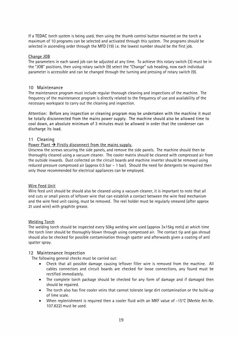
If a TEDAC torch system is being used, then using the thumb control button mounted on the torch a maximum of 10 programs can be selected and activated through this system. The programs should be selected in ascending order through the MFD (19) i.e. the lowest number should be the first job. Change JOB The parameters in each saved job can be adjusted at any time. To achieve this rotary switch (3) must be in the “JOB” positions, then using rotary switch (9) select the “Change” sub heading, now each individual parameter is accessible and can be changed through the turning and pressing of rotary switch (9). 10 Maintenance The maintenance program must include regular thorough cleaning and inspections of the machine. The frequency of the maintenance program is directly related to the frequency of use and availability of the necessary workspace to carry out the cleaning and inspection.
Attention: Before any inspection or cleaning program may be undertaken with the machine it must be totally disconnected from the mains power supply. The machine should also be allowed time to cool down, an absolute minimum of 3 minutes must be allowed in order that the condenser can discharge its load. 11 Cleaning Power Plant Firstly disconnect from the mains supply. Unscrew the screws securing the side panels, and remove the side panels. The machine should then be thoroughly cleaned using a vacuum cleaner. The cooler matrix should be cleaned with compressed air from the outside inwards. Dust collected on the circuit boards and machine inverter should be removed using reduced pressure compressed air (approx 0.5 bar – 1 bar). Should the need for detergents be required then only those recommended for electrical appliances can be employed. Wire Feed Unit Wire feed unit should be should also be cleaned using a vacuum cleaner, it is important to note that all end cuts or small pieces of leftover wire that can establish a contact between the wire feed mechanism and the wire feed unit casing, must be removed. The reel holder must be regularly smeared (after approx 2t used wire) with graphite grease. Welding Torch The welding torch should be inspected every 50kg welding wire used (approx 3x15kg reels) at which time the torch liner should be thoroughly blown through using compressed air. The contact tip and gas shroud should also be checked for possible contamination through spatter and afterwards given a coating of anti spatter spray. 12 Maintenance Inspection
The following general checks must be carried out: • Check that all possible damage causing leftover filler wire is removed from the machine. All
cables connectors and circuit boards are checked for loose connections, any found must be rectified immediately.
• The complete torch package should be checked for any form of damage and if damaged then should be repaired.
• The torch also has fine cooler veins that cannot tolerate large dirt contamination or the build-up of lime scale.
• When replenishment is required then a cooler fluid with an MKF value of -15°C (Merkle Art-Nr. 107.822) must be used.
19

• The models with water-cooling have 3,5 Litre capacity when connected by a 1,6m connecting cable.
• Fluid loss (mostly through changing of torch) must be replenished; otherwise the machine could cut out due to fluid pressure problems.
• If the machine looses too much fluid then the fluid pump may require recharging in order to remove the unwanted air from the system.
• If a contamination of the cooling fluid occurs then all the fluid must be changed for new. It is expected that the machine receive maintenance inspections at regular intervals.
• After the inspection has been completed the side panels should be reaffixed and secured into position be any welding can take place.
13 Problem Solving
Mains power control light does not light up when connected to mains supply. check mains connection fuse in the main control system defect
System fault control light indicates ‘red’ under or over voltage from mains over voltage trip system has deactivated the water pump General problem with the electronic circuitry
Water pump functions after turning on the machine but the ‘red’ control light is on Not enough pressure in the coolant system or the pressure valve is defect.
Temperature control light indicates ‘yellow’ Welding machine has overheated: do not turn the machine off the machine the cooling fans are
required to run, after the machine has cooled down and the temperature light has been reset the machine can be reused.
Temperature control light ‘yellow’ and fault control light indicates ‘red’ Fault in temperature sensor device
The machine does not react to the torch trigger being activated Torch trigger defect Welding process switch in MMA welding position
The machine delivers too low welding current Wrong program selected Earth cable connect to the wrong pole Defect along the torch power cable
Deposited weld bead has bad weld characteristics Arc length corrector – welding conditions set wrong Wrong gas The wire feed roller pressure wrongly set The torch liner requires cleaning or has a kink
Porosity in weld pool No or too little gas flow
20

Gas is mixing with air due to a leak in the line. The gas line should be checked from the pressure gauges to the gas valve in the wire feed unit as follows: open the gas bottle valve then close the gas valve in the wire feed unit, the pressure on the pressure gauges should remain constant Torch shroud or the gas diffuser is heavily contaminated causing poor gas flow to the job The gas diffuser is loose or loosely fitted on the torch (results in air being drawn through the torch
liner Badly oxidized work piece Air getting to the weld site, i.e. extreme movement of the air conditions at the weld site. (increase
gas flow and/or screen weld site) Gas flow meter valve is incorrect or 2 in series have been mistakenly fitted to the pressure gauge Gas flow to high causing gas saturation at the weld site
Poor wire feed problems causing irregular feed, constant burn-backs or chaffing of the wire on the contact-tip Too much pressure on the wire at the torch end Torch liner requires cleaning through Torch liner kinked Wrong liner fitted Check the welding wire for:
o Pressure setting on the wire feed rollers is set correctly o The surface of the wire is smooth and not contaminated or chaffed o The wire size is incorrect, too large for the machine set-up
Annealing of the welding wire Gas diffuser is loose or the torch coolant pipe is leaking causing the welding current to flow over
the welding wire or torch liner Overheating of the welding torch Check the coolant system Confirm coolant flow to the torch: disconnect the water return nipple, switch on machine and
check the coolant flows unhindered into a container Distance from work piece too small
Characteristics of Argon-CO2 welding gas
For steel and mild steel alloys an argon gas mix of approx 8-30% CO2 mix is required for: Protection against porosity in the weld pool Larger weld gaps can be bridged Spatter free welding Higher melting conditions Less precision torch control Easily capable of welding thin sheet and in positional welding the possibility of using impulse
welding programs Gas supply
Gas is available in steel bottles filled to a pressure of 200 bar, filled to 10, 20, and 50 litre content. For the setting of the gas flow a pressure gauge is fitted with a flow meter is used. The gas flow amount is dependant on: The desired gas density Type of material to be welded Distance from work piece to gas shroud Gas shroud diameter Welding position and type of weld Accessibility of the weld site
21

For steel welding the gas flow should be approximately between 8-16 l/min for welding currents ranging from 40-400 A By welding currents larger than 400 A the gas flow will be over 16 l/min When welding Aluminium the gas setting should be set at higher than with steel
22
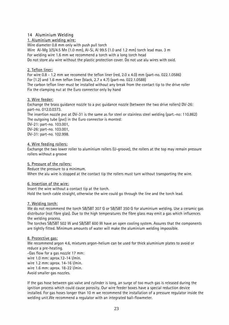
14 Aluminium Welding 1. Aluminium welding wire: Wire diameter 0.8 mm only with push pull torch Wire Al-Mg 3/5/4.5 Mn (1.0 mm), Al-Si, Al 99.5 (1.0 and 1.2 mm) torch lead max. 3 m For welding wire 1.6 mm we recommend a torch with a long torch head Do not store alu wire without the plastic protection cover. Do not use alu wires with oxid. 2. Teflon liner: For wire 0.8 - 1.2 mm we recomend the teflon liner (red, 2.0 x 4.0) mm (part-no. 022.1.0586) For (1.2) and 1.6 mm teflon liner (black, 2.7 x 4.7) (part-no. 022.1.0588) The carbon teflon liner must be installed without any break from the contact tip to the drive roller Fix the clamping nut at the Euro connector only by hand 3. Wire feeder: Exchange the brass guidance nozzle to a pvc guidance nozzle (between the two drive rollers) DV-26: part-no. 012.0.0373. The insertion nozzle pvc at DV-31 is the same as for steel or stainless steel welding (part.-no: 110.862) The outgoing tube (pvc) in the Euro connector is monted: DV-21: part-no. 103.001, DV-26: part-no. 103.001, DV-31: part-no. 102.998. 4. Wire feeding rollers: Exchange the two lower roller to aluminium rollers (U-groove), the rollers at the top may remain pressure rollers without a groove 5. Pressure of the rollers: Reduce the pressure to a minimum. When the alu wire is stopped at the contact tip the rollers must turn without transporting the wire. 6. Insertion of the wire: Insert the wire without a contact tip at the torch. Hold the torch cable straight, otherwise the wire could go through the line and the torch lead. 7. Welding torch: We do not recommend the torch SB/SBT 307 G or SB/SBT 350 G for aluminium welding. Use a ceramic gas distributor (not fibre glas). Due to the high temperatures the fibre glass may emit a gas which influences the welding process. The torches SB/SBT 502 W and SB/SBT 600 W have an open cooling system. Assures that the components are tightly fitted. Minimum amounts of water will make the aluminium welding impossible. 8. Protective gas: We recommend argon 4.6, mixtures argon-helium can be used for thick aluminium plates to avoid or reduce a pre-heating. -Gas flow for a gas nozzle 17 mm: wire 1.0 mm: aprox.12-14 l/min. wire 1.2 mm: aprox. 14-16 l/min. wire 1.6 mm: aprox. 18-22 l/min. Avoid smaller gas nozzles. If the gas hose between gas valve and cylinder is long, an surge of too much gas is released during the ignition process which could cause porosity. Our wire feeder boxes have a special reduction device installed. For gas hoses longer than 10 m we recommend the installation of a pressure regulator inside the welding unit.We recommend a regulator with an integrated ball-flowmeter.
23

9. Position and distance of the torch: Aluminium is welded in forward position, the torch is tilt aprox. 10 - 20°. Distance torch to work piece aprox. 10-15 mm. If the distance is too large, the protective gas shield is not assured. Avoid draught (air movement in the room). 10. Cleanliness: Aluminium work pieces must be thoroughly cleaned. Clean with alcohol or special aluminium cleaner Avoid the storage under high humidity. Remove oxid when aluminium pieces have been stored over a long period. 11. Additional wire equipment: In our general catalogues in section 10 we offer complete packages for wire equipments. 12. Special 4-stroke: We recommend to operate in the special 4-stroke mode with a higher start current. The start current, the down slop and the final current can be adjusted at the digital control unit.
24

15 Wire Feed Unit DV-31 Pos. Nr./no. Bezeichnung Description
A 113.846 DV-Ausrüstung Stahl 0,8 mm (DV-26/31) Kit for mild steel 0.8 mm (DV-26/31)
B 113.848 DV-Ausrüstung Stahl 1,0/1,2mm (DV-26/31) Kit for mild steel 1.0/1.2 mm (DV-26/31)
C 113.850 DV-Ausrüstung Stahl 1,6 mm (DV-26/31) Kit for mild steel 1.6 mm (DV-26/31)
D 113.852 DV-Ausrüstung VA 0,8 mm (DV-26/31) Kit for stainl. steel 0.8 mm (DV-26/31)
E 113.854 DV-Ausrüstung VA 1,0/1,2 mm (DV-26/31) Kit for stainl. steel 1.0/1.2 (DV-26/31)
F 113.856 DV-Ausrüstung VA 1,6 mm (DV-26/31) Kit for stainl. steel 1.6 mm (DV-26/31)
G 113.858 DV-Ausrüstung Alu 0,8 mm (DV-26/31) Kit for aluminium 0.8 mm (DV-26/31)
H 113.860 DV-Ausrüstung Alu 1,0/1,2 mm (DV-26/31) Kit for aluminium 1.0/1.2 mm (DV-26/31)
I 113.862 DV-Ausrüstung Alu 1,6 mm (DV-26/31) Kit for aluminium 1.6 mm (DV-26/31) J 113.864 DV-Ausrüstung Fülldraht 1,2 mm (DV-31) Kit for core wire 1.2 mm (DV-26/31)
K 113.866 DV-Ausrüstung Fülldraht 1,6 mm (DV-31) Kit for core wire 1.6 mm (DV-26/31) L 113.868 DV-Ausrüstung Fülldraht 2,0/2,4 mm DV-31 Kit for core wire 2.0/2.4 mm DV-31
M 113.870 DV-Ausrüstung Fülldraht 2,8 mm (DV-31) Kit for core wire 2.8 mm DV-31
O 113.872 DV-Ausrüstung Fülldraht 3,2 mm (DV-31) Kit for core wire 3.2 mm DV-31 0 Einzelkomponenten für Drahtvorschub: Components additional wire equipm.:
0.1 113.742 Druckrolle DV-26/31 Pressure roller DV-26/31
0.2 110.560 Rollenträger DV 26, 31, 30/4 Roller support DV-31, 30/4
25
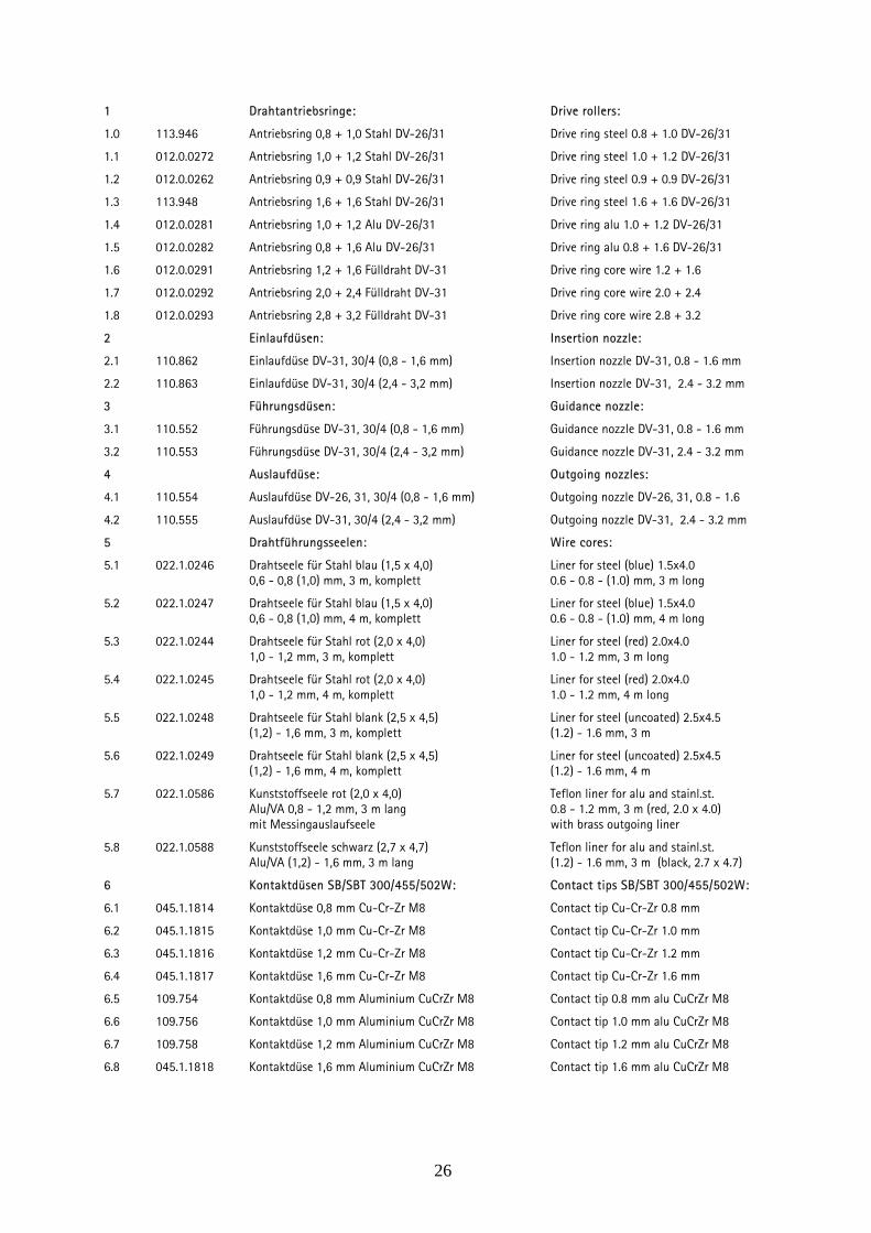
1 Drahtantriebsringe: Drive rollers:
1.0 113.946 Antriebsring 0,8 + 1,0 Stahl DV-26/31 Drive ring steel 0.8 + 1.0 DV-26/31
1.1 012.0.0272 Antriebsring 1,0 + 1,2 Stahl DV-26/31 Drive ring steel 1.0 + 1.2 DV-26/31
1.2 012.0.0262 Antriebsring 0,9 + 0,9 Stahl DV-26/31 Drive ring steel 0.9 + 0.9 DV-26/31
1.3 113.948 Antriebsring 1,6 + 1,6 Stahl DV-26/31 Drive ring steel 1.6 + 1.6 DV-26/31
1.4 012.0.0281 Antriebsring 1,0 + 1,2 Alu DV-26/31 Drive ring alu 1.0 + 1.2 DV-26/31
1.5 012.0.0282 Antriebsring 0,8 + 1,6 Alu DV-26/31 Drive ring alu 0.8 + 1.6 DV-26/31
1.6 012.0.0291 Antriebsring 1,2 + 1,6 Fülldraht DV-31 Drive ring core wire 1.2 + 1.6
1.7 012.0.0292 Antriebsring 2,0 + 2,4 Fülldraht DV-31 Drive ring core wire 2.0 + 2.4
1.8 012.0.0293 Antriebsring 2,8 + 3,2 Fülldraht DV-31 Drive ring core wire 2.8 + 3.2
2 Einlaufdüsen: Insertion nozzle:
2.1 110.862 Einlaufdüse DV-31, 30/4 (0,8 - 1,6 mm) Insertion nozzle DV-31, 0.8 - 1.6 mm
2.2 110.863 Einlaufdüse DV-31, 30/4 (2,4 - 3,2 mm) Insertion nozzle DV-31, 2.4 - 3.2 mm
3 Führungsdüsen: Guidance nozzle:
3.1 110.552 Führungsdüse DV-31, 30/4 (0,8 - 1,6 mm) Guidance nozzle DV-31, 0.8 - 1.6 mm
3.2 110.553 Führungsdüse DV-31, 30/4 (2,4 - 3,2 mm) Guidance nozzle DV-31, 2.4 - 3.2 mm
4 Auslaufdüse: Outgoing nozzles:
4.1 110.554 Auslaufdüse DV-26, 31, 30/4 (0,8 - 1,6 mm) Outgoing nozzle DV-26, 31, 0.8 - 1.6
4.2 110.555 Auslaufdüse DV-31, 30/4 (2,4 - 3,2 mm) Outgoing nozzle DV-31, 2.4 - 3.2 mm
5 Drahtführungsseelen: Wire cores:
5.1 022.1.0246 Drahtseele für Stahl blau (1,5 x 4,0) Liner for steel (blue) 1.5x4.0 0,6 - 0,8 (1,0) mm, 3 m, komplett 0.6 - 0.8 - (1.0) mm, 3 m long
5.2 022.1.0247 Drahtseele für Stahl blau (1,5 x 4,0) Liner for steel (blue) 1.5x4.0 0,6 - 0,8 (1,0) mm, 4 m, komplett 0.6 - 0.8 - (1.0) mm, 4 m long
5.3 022.1.0244 Drahtseele für Stahl rot (2,0 x 4,0) Liner for steel (red) 2.0x4.0 1,0 - 1,2 mm, 3 m, komplett 1.0 - 1.2 mm, 3 m long
5.4 022.1.0245 Drahtseele für Stahl rot (2,0 x 4,0) Liner for steel (red) 2.0x4.0 1,0 - 1,2 mm, 4 m, komplett 1.0 - 1.2 mm, 4 m long
5.5 022.1.0248 Drahtseele für Stahl blank (2,5 x 4,5) Liner for steel (uncoated) 2.5x4.5 (1,2) - 1,6 mm, 3 m, komplett (1.2) - 1.6 mm, 3 m
5.6 022.1.0249 Drahtseele für Stahl blank (2,5 x 4,5) Liner for steel (uncoated) 2.5x4.5 (1,2) - 1,6 mm, 4 m, komplett (1.2) - 1.6 mm, 4 m
5.7 022.1.0586 Kunststoffseele rot (2,0 x 4,0) Teflon liner for alu and stainl.st. Alu/VA 0,8 - 1,2 mm, 3 m lang 0.8 - 1.2 mm, 3 m (red, 2.0 x 4.0) mit Messingauslaufseele with brass outgoing liner
5.8 022.1.0588 Kunststoffseele schwarz (2,7 x 4,7) Teflon liner for alu and stainl.st. Alu/VA (1,2) - 1,6 mm, 3 m lang (1.2) - 1.6 mm, 3 m (black, 2.7 x 4.7)
6 Kontaktdüsen SB/SBT 300/455/502W: Contact tips SB/SBT 300/455/502W:
6.1 045.1.1814 Kontaktdüse 0,8 mm Cu-Cr-Zr M8 Contact tip Cu-Cr-Zr 0.8 mm
6.2 045.1.1815 Kontaktdüse 1,0 mm Cu-Cr-Zr M8 Contact tip Cu-Cr-Zr 1.0 mm
6.3 045.1.1816 Kontaktdüse 1,2 mm Cu-Cr-Zr M8 Contact tip Cu-Cr-Zr 1.2 mm
6.4 045.1.1817 Kontaktdüse 1,6 mm Cu-Cr-Zr M8 Contact tip Cu-Cr-Zr 1.6 mm
6.5 109.754 Kontaktdüse 0,8 mm Aluminium CuCrZr M8 Contact tip 0.8 mm alu CuCrZr M8
6.6 109.756 Kontaktdüse 1,0 mm Aluminium CuCrZr M8 Contact tip 1.0 mm alu CuCrZr M8
6.7 109.758 Kontaktdüse 1,2 mm Aluminium CuCrZr M8 Contact tip 1.2 mm alu CuCrZr M8
6.8 045.1.1818 Kontaktdüse 1,6 mm Aluminium CuCrZr M8 Contact tip 1.6 mm alu CuCrZr M8
26

16 Torches and Spare Parts
For torch model SB/SBT 502 W
Technical data: Cooling: water cooled Mixed gas: 500 A 60 % duty cycle CO2: 500 A 100 % duty cycle Wire diameter: Solid wire: 0.8 – 1.0 – 1.2 – 1.6 mm ∅ Aluminium wire: 1.0 – 1.2 – 1.6 mm ∅ Weight: approx. 1300 g/1 m H The data are corresponding to (U = 14 + 0.05 x I) Torch model SB/SBT 502 W MIG/MAG hand welding torch 022.1.1587 model SB 502 W, 3 m, short version MIG/MAG hand welding torch 022.1.1588 model SB 502 W, 4 m, short version MIG/MAG hand welding torch 022.1.1581 model SB 502 W, 3 m, long version MIG/MAG hand welding torch 022.1.1582 model SB 502 W, 3 m, long version MIG/MAG hand welding torch 022.1.1601 TEDAC, SBT 502 W, 3 m, short vers. MIG/MAG hand welding torch 022.1.1602 TEDAC, SBT 502 W, 4 m, short vers. MIG/MAG hand welding torch 022.1.1603 TEDAC, SBT 502 W, 3 m, long vers. MIG/MAG hand welding torch 022.1.1604 TEDAC, SBT 502 W, 4 m, long vers. Standard wire equipment: mild steel 1.2
27

MIG Welding torch model SB/SBT 502 W, watercooled
28
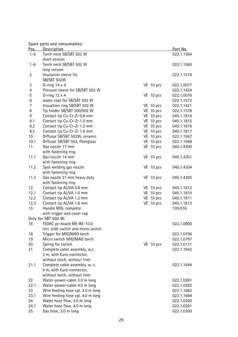
Spare parts and consumables: Pos. Description Part No. 1-6 Torch neck SB/SBT 502 W 022.1.1564
short version 1-6 Torch neck SB/SBT 502 W 022.1.1560
long version 2 Insulation sleeve for 022.1.1574
SB/SBT 502W 3 O-ring 14 x 4 VE 10 pcs 022.1.0077 4 Pressure sleeve for SB/SBT 502 W 022.1.1424 5 O-ring 12 x 4 VE 10 pcs 022.1.0076 6 water coat for SB/SBT 502 W 022.1.1572 7 Insualtion ring SB/SBT 502 W VE 10 pcs 022.1.1421 8 Tip holder SB/SBT 300/502 W VE 10 pcs 022.1.1578 9 Contact tip Cu-Cr-Zr 0.8 mm VE 10 pcs 045.1.1814 9.1 Contact tip Cu-Cr-Zr 1.0 mm VE 10 pcs 045.1.1815 9.2 Contact tip Cu-Cr-Zr 1.2 mm VE 10 pcs 045.1.1816 9.3 Contact tip Cu-Cr-Zr 1.6 mm VE 10 pcs 045.1.1817 10 Diffusor SB/SBT 502W, ceramic VE 10 pcs 022.1.1567 10.1 Diffusor SB/SBT 502, fibreglass VE 10 pcs 022.1.1568 11 Gas nozzle 17 mm VE 10 pcs 045.1.4300
with fastening ring 11.1 Gas nozzle 14 mm VE 10 pcs 045.1.4301
with fastening ring 11.2 Spot welding gas nozzle VE 10 pcs 045.1.4304
with fastening ring 11.3 Gas nozzle 21 mm heavy duty VE 10 pcs 045.1.4305
with fastening ring 12 Contact tip AL/VA 0.8 mm VE 10 pcs 045.1.1812 12.1 Contact tip AL/VA 1.0 mm VE 10 pcs 045.1.1810 12.2 Contact tip AL/VA 1.2 mm VE 10 pcs 045.1.1811 12.3 Contact tip AL/VA 1.6 mm VE 10 pcs 045.1.1813 15 Handle MIG, complete 105.016
with trigger and cover cap Only for SBT 502 W: 16 TEDAC pc-board ME-BE-10.0 022.1.0800
incl. slide switch and micro switch 18 Trigger for MIG/MAG torch 022.1.0796 19 Micro switch MIG/MAG torch 022.1.0797 20 Spring for switch VE 10 pcs 022.1.0131 21 Complete cable assembly, w.c. 022.1.1642
3 m, with Euro-connector, without torch, without liner
21.1 Complete cable assembly, w. c. 022.1.1644 4 m, with Euro-connector, without torch, without liner
22 Water-power-cable 3.0 m long 022.1.0281 22.1 Water-power-cable 4.0 m long 022.1.0282 23 Wire feeding hose cpl. 3.0 m long 022.1.1662 23.1 Wire feeding hose cpl. 4.0 m long 022.1.1664 24 Water hose flow, 3.0 m long 022.1.0290 24.1 Water hose flow, 4.0 m long 022.1.0291 25 Gas hose, 3.0 m long 022.1.0300
29

Pos. Description Part No. 25.1 Gas hose, 4.0 m long 022.1.0301 26 Switch-cable, 3 m long 022.1.0148 26.1 Switch-cable, 4 m long 022.1.0149 27 Protective-hose, 3.0 m long 006.0.1055 27.1 Protective-hose, 4.0 m long 006.0.1054 28 Liner for steel (blue) 022.1.0246
0.6 - 0.8 (1.0) mm, 3 m long 28.1 Liner for steel (blue) 022.1.0247
0.6 - 0.8 (1.0) mm, 4 m long 28.2 Liner for steel (uncoated), 022.1.0248
1.0 - 1.6 mm, 3 m 28.3 Liner for steel (uncoated), 022.1.0249 1,0 - 1.6 mm, 4 m 30 Euro-connection, at torch side 025.1.0150 31 Brass neck for Euro-connection 025.1.0200 32 Kinking-protection, intake 025.1.0100 33 Euro adapter nut 025.1.0300 34 Liner nut VE 10 pcs 025.1.1301 35 Water-return-hose 022.1.0295 36 Coupling nipple no. 3305 025.1.0400 37 Teflon liner for alu and stainl.st. 022.1.0586
0.8 - 1.2 mm, 3 m (red, 2.0 x 4.0) with brass outgoing liner
37.1 Teflon liner for alu and stainl.st. 022.1.0588 (1.2) - 1.6 mm, 3 m (black, 2.7 x 4.7) with brass outgoing liner
38.1 Collet for teflon liner 2.0 x 4.0 min 10 pcs 107.554 38.2 Collet for teflon liner 2.7 x 4.7 min 10 pcs 102.997 39.1 Outgoing nozzle pvc, DV-25/4 103.001
for aluminium and stainless steel 39.2 Outgoing nozzle pvc, DV-30/4 102.998
for aluminium and stainless steel, 0.8 - 1.6 mm 1.2 - 1.6 mm, 3 m (2.7 x 4.7 mm)
41 Kinking protection 022.1.1580 42 Spring for kinking protection 022.1.1579 43 Connection nipple for VE 10 pcs 045.1.0201
water-current-cable, torch side 44 Nipple for wire feeding hose at VE 10 pcs 045.1.0312
torch side Protection hose 26 x 1.5 VE 120 m 027.2.0100 Water hose blue 5 x 1.5 VE 100 m 027.2.0130 Water hose red 5 x 1.5 VE 100 m 027.2.0125 PVC hose with textile 9 x 12 mm VE 100 m 006.0.0103
Only for SB 502 W: 45 Cover cap for TEDAC handle 022.1.0604
* max. length of torch lead for alu: 3 m.
17 Wire diagrams
30

1 2 3 4 5 6 7 8
4321
2 12 12 1 2 1
-V3 -V4
-V1
~~ ~
+-
- V2
~~ ~
+-
2
1
4
3
2
1
+SQ-A14 -X1 /2 .4+SQ-A18 -X1 /2 .4
+SQ-A26 -X2 /4 .5+SQ-A10 -X1 /2 .3
-R3
-F9
+SQ-A26-X13 :1 /4 .5+SQ-A26-X13 :2 /4 .5
+SQ-V10 :4 /2 .4
+SQ-A26-X12 :1 /4 .3+SQ-A26-X12 :2 /4 .3
+SQ-V18 :4 /2 .4
+SQ-V5 :3 /2 .2
+SQ-V13 :3 /2 .2
-A1L 1 L 2 L 3 P E
L1´L2´L3´ ME
-EM
V-3
.1
+SQ-A26-X8 :1 /4 .3+SQ-A26-X8 :2 /4 .3+SQ-A26-X8 :3 /4 .3+SQ-A26-X8 :4 /4 .3
-X0
P E
N
L 3
L 2
L 1
-A0L 1 L 2 L 3 P E
L1´L2´L3´ ME
-EM
V-3
.1
E rdungs-sch raube
- Q 1L 1 L 2 L 3
T 1 T 2 T 3
-A2
1 2 3 4
~~ ~
+-
gn
Pr.
DC U<
U>
ge
rt
ME - I44 -PG-10
12 12
X 5 X 7X 8
~~ ~
+-
12 12
X 4
9 V A CX 6
-A3
X 1 216 1
Star t
gn
T > 8 0
ge
S toe
rt
+ 1 6 V a
gn
X 1 116 1+ 1 6 V b
gn
ME- I44 -PSRS-1 .1
1
2
3
4
1
2
X 11 40
1
X 2
10 X 3
1 2 3 4 X 4
U V S
gn
Istat
ge
Idyn
rt
X 5
N T C
1 8 V A C
swsw
swg
nsw
rt
swb
l
swsw
sw
ws-
sww
s-b
lw
s-b
ng
nw
s-r
trt
bl
s wb n
rtbl
v io -swv io -sw bl
r t -swr t -sw
blbl
r t -ger t -ws
w sw s
blbl
Fer i t t r ing 3 Wdg.
3PH-400V /50 -60Hz /PE
N T C
Thermoscha l te r
F lachbandkabe lf la t band cable
F lachbandkabe l
F lachbandkabe lf la t band cable
F lachbandkabe l
B l a t t
7 B l .
1
Pro jektbez.
Auf t ragsnr. Ze ichnungsnr .
H ighpuls 450-550Änderung Da tum
gez .
gep r .
NameDa tum Name
K o n r a d0 3 . 1 0 . 0 5 Schweißst romkre is
Ve
rvie
lfä
ltig
un
g o
de
r W
eit
erg
ab
e n
ur
mit
un
se
rer
sc
hri
ftli
ch
en
Ge
ne
hm
igu
ng
ge
sta
tte
t
cd
ab
P l o t d a t u m : 2 9 . 0 5 . 0 6
M e r k l eS c h w e i ß a n l a g e n - T e c h n i k G m b HI n d u s t r i e s t r a ß e 3D - 8 9 3 5 9 K ö t zT e l e f o n 0 8 2 2 1 - 9 1 5 - 0T e l e f a x 0 8 2 2 1 - 3 2 5 9 6
=+ S Q

1 2 3 4 5 6 7 8
-V17
12
43
- V18
12
43
- V9
12
43
- V10
12
43
- A5
ME
-I44-PF
-1.0
- A7
ME
-I44-PF
-1.0
- A9
110X 1
S5
S2
S3
S4
S1
ME-
PI/C
-1.1
_S3
- A11
110X 1
S5
S2
S3
S4
S1
ME-
PI/C
-1.1
_S4
- A14
GA
TE
SO
U
GA
TE
SO
U
116 A.B. -S3
X 1ME- I4 -GT-1 .0
GA
TE
SO
U
GA
TE
SO
U
116 A.B. -S3
X 1ME- I4 -GT-1 .0
-A15
SO
U SO
U
GA
TE
GA
TE
ME- I4 -GT-1 .0 C.D. -S41 16X 1S
OU SO
U
GA
TE
GA
TE
ME- I4 -GT-1 .0 C.D. -S41 16X 1
-A18G
ATE
SO
U
GA
TE
SO
U
116 A.B. -S4
X 1ME- I4 -GT-1 .0
GA
TE
SO
U
GA
TE
SO
U
116 A.B. -S4
X 1ME- I4 -GT-1 .0
-A19
SO
U SO
U
GA
TE
GA
TE
ME- I4 -GT-1 .0 A.B. -S41 16X 1S
OU SO
U
GA
TE
GA
TE
ME- I4 -GT-1 .0 A.B. -S41 16X 1
-V13
12
43
- V14
12
43
- V5
12
43
- V6
12
43
- A4
ME
-I44-PF
-1.0
- A6
ME
-I44-PF
-1.0
- A8
110X 1
S5
S2
S3
S4
S1
ME-
PI/C
-1.1
_S1
- A10
110X 1
S5
S2
S3
S4
S1
ME-
PI/C
-1.1
_S2
- A12
GA
TE
SO
U
GA
TE
SO
U
116 A.B. -S1
X 1ME- I4 -GT-1 .0
GA
TE
SO
U
GA
TE
SO
U
116 A.B. -S1
X 1ME- I4 -GT-1 .0
-A13
SO
U SO
U
GA
TE
GA
TE
ME- I4 -GT-1 .0 C.D. -S21 16X 1S
OU SO
U
GA
TE
GA
TE
ME- I4 -GT-1 .0 C.D. -S21 16X 1
-A16
GA
TE
SO
U
GA
TE
SO
U
116 A.B. -S2
X 1ME- I4 -GT-1 .0
GA
TE
SO
U
GA
TE
SO
U
116 A.B. -S2
X 1ME- I4 -GT-1 .0
-A17
SO
U SO
U
GA
TE
GA
TE
ME- I4 -GT-1 .0 A.B. -S21 16X 1S
OU SO
U
GA
TE
GA
TE
ME- I4 -GT-1 .0 A.B. -S21 16X 1
-A20
ME- I44 -RCD-1 .0
-V23
243
1
- V24
243
1
- V25
243
1
- V26
243
1
- T1
2 3
2 1
1 3
1 1
1 0
9
8
7
6
5
4
3
2
1
-A21
ME- I44 -RCD-1 .0
-V27
243
1
- V28
243
1
- V30
243
1
- V29
243
1
- T2
2 3
2 1
1 3
1 1
1 0
9
8
7
6
5
4
3
2
1
+SQ-A3 -X11 /1 .6+SQ-A3-X2 /1 .5
+SQ-V1 :+ /1 .2+SQ-A2-X5 :1 /1 .2
+SQ-A3 -X12 /1 .6
+SQ-V2 :+ /1 .4+SQ-A2-X4 :1 /1 .4
-L1
-L2
-X3
-X2
+SQ-A26-X9 :3 /4 .7
-A222 3 41
4321
+SQ-A26-X9 :1 /4 .7
-X1
+
-Z1
+SQ-A26-X18 :4 /4 .7+SQ-A26-X18 :3 /4 .7+SQ-A26-X18 :2 /4 .7+SQ-A26-X18 :1 /4 .7
-V211
2
4
3
-V221
2
4
3
-V7
1 2
4 3
- V8
1 2
4 3
- V11
1 2
4 3
- V12
1 2
4 3
- V15
1 2
4 3
- V16
1 2
4 3
- V19
1 2
4 3
- V20
1 2
4 3
E lek t rode
Werks tück
codier t auf S1 codier t auf S3
codier t auf S4codier t auf S2
F lachbandkabe lf la t band cable
B l a t t
7 B l .
2
Pro jektbez.
Auf t ragsnr. Ze ichnungsnr .
H ighpuls 450-550Änderung Da tum
gez .
gep r .
NameDa tum Name
K o n r a d1 9 . 1 2 . 0 5 Schweißst romkre is
Ve
rvie
lfä
ltig
un
g o
de
r W
eit
erg
ab
e n
ur
mit
un
se
rer
sc
hri
ftli
ch
en
Ge
ne
hm
igu
ng
ge
sta
tte
t
cd
ab
P l o t d a t u m : 2 9 . 0 5 . 0 6
M e r k l eS c h w e i ß a n l a g e n - T e c h n i k G m b HI n d u s t r i e s t r a ß e 3D - 8 9 3 5 9 K ö t zT e l e f o n 0 8 2 2 1 - 9 1 5 - 0T e l e f a x 0 8 2 2 1 - 3 2 5 9 6
=+ S Q

1 2 3 4 5 6 7 8
+SQ-A26-X3 :4 /4 .5+SQ-A26-X3 :3 /4 .5+SQ-A26-X3 :2 /4 .5+SQ-A26-X3 :1 /4 .5
+SQ-A26 -X1 /4 .6 9
1 0
1 3
1 4
1 7
1 8
1 9
1 6
1 5
1 1
1 2
7
8
6
5
2
1
3
4
+SQ-A27 -X3 /5 .7
2 0
2 3
2 4
2 2
2 1
+SQ-A26 -X6 /4 .4+SQ-A26 -X17 /4 .4
-A24
110
ge
X 2
3
4
5
6
1
2
3
4
5
6
1
2
ME-2QR-24 /42 -2 .2
+-
-+
X 1
4 2 V / A C
T A C H O
A N K E R /core
-15V
+ 1 5 V
U Sol l
+ 5 V
G N D
X 3
F r e i g a b e /e n a b l e
B r e m s e n /b r a k e
F r e i g a b e /e n a b l e
gn
max
min
12
34
56
78
910
1112
on T /A
T /AT /AA/TC 1C 2C 3C 4R 1R 2R 3R 4 M
E-2
QR
/DIP
-1.0 - A25
12
34
56
78
910
1112
on T /A
T /AT /AA/TC 1C 2C 3C 4R 1R 2R 3R 4 M
E-2
QR
/DIP
-1.0
6
5
4
3
2
1
4321 4321
4
3
2
1
+SQ-A26-X9 :4 /4 .7
+SQ-A26-X7 :2 /4 .5
+SQ-A26-X7 :1 /4 .5
+ O P 1-A28 -X2
6
5
4
3
2
1
-C1
-A23
1 10
X 5
1 6
X 3
101 2 3 4 5 6 7 8 91 2 3 41 2 3 4X 2X 1 X 4
X 7
1
6
S 1
X 8
1
20
1
X 96
1
2
3
4
X 1 6
10
1
X 1 7
X 1 16 1
X 1 3110
X 1 434 118
X 1 5
J P 1
M E - M T C 3 2 - 3 . 2
X 1 0
E n
Kor r
3 ,3V
+5
V
+2
4V
-RS
23
2
b n
w s
g eorrs
v iow s
b n g n
sw-gn
w sb n
rsv io
w srtbls w
v io -sw
b n v io-gew s b l -gnv io sw-r t
rs s w / w s
F lachbandkabe lf la t band cable
F lachbandkabe lf la t band cable
Op
tio
n P
us
h-P
ull
0 , 1uF1 0 0 0 V
P i n b e l e g u n g 1 0 p o l i g . F l a c h b a n d k a b e l- A 2 3 : X 5 n a c h R S 2 3 2 S c h n i t t s t e l l e
- A 2 3 - X 5 R S 2 3 2123456789
1 0
123456789
1 0
G N D
rxd
txd
rts
cts
F lachbandkabe lf la t band cable
B l a t t
7 B l .
3
Pro jektbez.
Auf t ragsnr. Ze ichnungsnr .
H ighpuls 450-550Änderung Da tum
gez .
gep r .
NameDa tum Name
K o n r a d0 3 . 1 0 . 0 5 Steuerst romkre is
Ve
rvie
lfä
ltig
un
g o
de
r W
eit
erg
ab
e n
ur
mit
un
se
rer
sc
hri
ftli
ch
en
Ge
ne
hm
igu
ng
ge
sta
tte
t
cd
ab
P l o t d a t u m : 2 9 . 0 5 . 0 6
M e r k l eS c h w e i ß a n l a g e n - T e c h n i k G m b HI n d u s t r i e s t r a ß e 3D - 8 9 3 5 9 K ö t zT e l e f o n 0 8 2 2 1 - 9 1 5 - 0T e l e f a x 0 8 2 2 1 - 3 2 5 9 6
=+ S Q

1 2 3 4 5 6 7 8
+SQ-A23-X1 :4 /3 .2+SQ-A23-X1 :3 /3 .2
+SQ-A23-X1 :1 /3 .2+SQ-A23-X1 :2 /3 .2
+SQ-A22-X1 :4 /2 .7+SQ-A22-X1 :3 /2 .7
+SQ-A22-X1 :1 /2 .7+SQ-A22-X1 :2 /2 .7- M 7 M
=
+SQ-X8 :21 /3 .8
4321
4
3
2
14321
2 12 11A
t
4A
t
4A
t
2
1
+SQ-A24-X1 :4 /3 .3+SQ-A24-X1 :3 /3 .3+SQ-Q1 :T2 /1 .1+SQ-Q1 :T1 /1 .1
+SQ-X8 :8 /3 .8+SQ-X8 :7 /3 .8
+SQ-X2 /2 .8
+SQ-X3 /2 .8
+SQ-A27-X1 :4 /5 .6+SQ-A27-X1 :3 /5 .6+SQ-A27-X1 :2 /5 .6+SQ-A27-X1 :1 /5 .6
+SQ-A23 -X14 /3 .3+SQ-A3-X1 /1 .5
+SQ-A3-X3 :2 /1 .6+SQ-A3-X3 :1 /1 .6
+SQ-A2-X6 :4 /1 .4+SQ-A2-X6 :3 /1 .4+SQ-A2-X6 :2 /1 .4+SQ-A2-X6 :1 /1 .4
- M 5
P E
M- M 6
P E
M
6
6
7
7
8
8
9
9
1 0
1 0
- M 3
P E
M- M 4
P E
M
-X5
5
5
4
4
3
3
2
2
1
1
- M 2P E
bn
sw bl
M
-F14
2 1
-S11
2
3
Hand /Au tomat i k
-X7
1
2
3
4
5
6
-F13
P
Erdungs-sch raube
-F7
10At
-F8
1 A
-F5 1 A
-F4
4 A
-F6
4 A
-T3
0 V
4 0 0 V
2 3 0 V
P E
0 V
4 2 V
0 V
3 7
4 4 0 V
4 0 0
2,5A
0,5A
+SQ-X8 :10 /3 .8+SQ-X8 :9 /3 .8
-A26
12123456121 X 4 X 1 0 X 1 1X 52
1
2
3
4
X 91 2 3 4 X 3 40 1
X 234 1
X 1
rt
Cal ib
1
2
4
3
X 8
X 1 4 ME- I44-T IF-1 .1
X 1 221
X 1 31
2 X 1 8
+1
5V
-15
V
Iis
t
1 2 3 4
+5
V
+2
4V9 V A C
gn
P u m p e
gn
V e n t i l a t o r
F1
F2
F3
4 4 0 V
4 0 0 V
2 3 0 V
X 1 6
2 2 V A C
X 1 5
X 6 X 1 7
F 4
3 7 V A C
4 2 V A C
F 5
1234 X 7
G a s 1I>0
ge
G a s 1
rt rt ge
I>0 H F G a s 2
4
3
2
1
4 3 2 1 6 5 4 3 2 1
bl
ge
-sw
ge- r t
s w - w sw s
w ss w sw-r t
s w - w sb n v io
rs
s wb nrs
v iob l -ws g n
bl sw-gns w w s
b ns w - w s
w sw s - s w rtws-b lws -bn blws-r t
r t -wsr t -ge
rt
s w g ngr
w ss w
b n b nw s w sv io v io
rs rs
.2
Lüf ter auf Plat ineM E - M T C 3 2
Lü
fte
r/fa
nIn
ve
rte
r
Lü
fte
r/fa
nK
üh
ler
Pu
mp
e/
pum
p
M o t o r s c h u t z
Brücke be i Opt ionAutomatenansch luß en t fe rnen
remove br idge wi th opt ionmach ine we ld ing connect io
Wa
ss
erd
ruc
ks
ch
alt
er
Op
tio
n:
Au
tom
ate
na
ns
ch
luß
ma
ch
ine
we
ldin
g c
on
ne
cti
on
F l achbandkabe lf la t band cableF lachbandkabe l
B l a t t
7 B l .
4
Pro jektbez.
Auf t ragsnr. Ze ichnungsnr .
H ighpuls 450-550Änderung Da tum
gez .
gep r .
NameDa tum Name
K o n r a d0 3 . 1 0 . 0 5 Steuerst romkre is
Ve
rvie
lfä
ltig
un
g o
de
r W
eit
erg
ab
e n
ur
mit
un
se
rer
sc
hri
ftli
ch
en
Ge
ne
hm
igu
ng
ge
sta
tte
t
cd
ab
P l o t d a t u m : 2 9 . 0 5 . 0 6
M e r k l eS c h w e i ß a n l a g e n - T e c h n i k G m b HI n d u s t r i e s t r a ß e 3D - 8 9 3 5 9 K ö t zT e l e f o n 0 8 2 2 1 - 9 1 5 - 0T e l e f a x 0 8 2 2 1 - 3 2 5 9 6
=+ S Q

1 2 3 4 5 6 7 8
4
3
2
1+SQ-A26-X3 :1 /4 .5+SQ-A26-X3 :2 /4 .5+SQ-A26-X3 :3 /4 .5+SQ-A26-X3 :4 /4 .5
+SQ-A23 -X9 /3 .5
+ O P 1-A28
rt
Fre igabe/enab le
X 4
M E - P P M R - 2 . 1
X 11
2
3
4
5
6
7
8
X 21
2
3
4
5
6
1 10X 3
J P 1
J P 2
> 3 m
1A- t räge/s low
+ O P 1-A29
M E - P P M R / A N 2 . 0
rt
+
rt
gn
0
-
110X 1
-A27
A
Vm / m i nm m
Ho ld
3030
0
20
10 10
20
0
50
20
40 60
90
1 0 0
rt
ge
%- % +
M I G / M A G
P U L S E
I N T E R P U L S E
E L E K T R O D E
T IG
J O B
T E D A C
M E - M T C 3 2 F R - 1 . 1
X 6
1
2
3
4
5
6
X 4
6
1
1
6
X 3
1
2
3
4
X 1
12X 2
+ 5 V
+ 2 4 Vrsv iow sb n
F lachbandkabe l
f la t band cable
B l a t t
7 B l .
5
Pro jektbez.
Auf t ragsnr. Ze ichnungsnr .
H ighpuls 450-550Änderung Da tum
gez .
gep r .
NameDa tum Name
K o n r a d0 3 . 1 0 . 0 5 Steuerst romkre is
Ve
rvie
lfä
ltig
un
g o
de
r W
eit
erg
ab
e n
ur
mit
un
se
rer
sc
hri
ftli
ch
en
Ge
ne
hm
igu
ng
ge
sta
tte
t
cd
ab
P l o t d a t u m : 2 9 . 0 5 . 0 6
M e r k l eS c h w e i ß a n l a g e n - T e c h n i k G m b HI n d u s t r i e s t r a ß e 3D - 8 9 3 5 9 K ö t zT e l e f o n 0 8 2 2 1 - 9 1 5 - 0T e l e f a x 0 8 2 2 1 - 3 2 5 9 6
=+ S Q

1 2 3 4 5 6 7 8
1
2
3
4
5
6
7
8
9
1 0
1 1
1 2
1 3
1 4
1 5
1 6
1 7
1 8
1 9
2 0
2 1
2 2
2 3
+ V B-X8
2 4
1
2
3
4
5
6
7
8
9
1 0
1 1
1 2
1 3
1 4
1 5
1 6
1 7
1 8
1 9
2 0
2 1
2 2
2 3
-X9
2 4
2
3
4
5
6
7
8
9
1 0
1 1
1 2
1 3
1 4
1 5
1 6
1 7
1 8
1 9
2 0
2 1
2 2
2 3
1
- M 1
+ -
+ -G=
M=
+ V B-X9
2 4
-Y1
+ O P 1-X10
B
A
K
J
H
G
F
E
D
C
M=
E
A
S
E
A
S
-S3
-R1E
A
S
-R2E
A
S
-S11
2
3
-S21
2
3
B
A-X6
+
+ V B-X1
2 4
2 3
2 1
1 7
1 5
1 4
1 31 2
1 0
9
8
7
Energy
BT.
BT .
PP-Moto r
Energy
B
A
Opt ion:PP-und Fernreg le ransch luß/
remote cont ro l
Zent ra lansch luß(Ans icht Masch inenf ront )
EURO connec to r ( f ront v iew)
VB-Kabe l /connect ion cab le
DV-Gerä t DV-30 /4wi re feeder
Taster Draht /bot ton wi re feed
Korrektur /t r im
Korrektur /t r im
B l a t t
7 B l .
6
Pro jektbez.
Auf t ragsnr. Ze ichnungsnr .
H ighpuls 450-550Änderung Da tum
gez .
gep r .
NameDa tum Name
K o n r a d0 4 . 0 1 . 0 6 DV-Kas ten
Ve
rvie
lfä
ltig
un
g o
de
r W
eit
erg
ab
e n
ur
mit
un
se
rer
sc
hri
ftli
ch
en
Ge
ne
hm
igu
ng
ge
sta
tte
t
cd
ab
P l o t d a t u m : 2 9 . 0 5 . 0 6
M e r k l eS c h w e i ß a n l a g e n - T e c h n i k G m b HI n d u s t r i e s t r a ß e 3D - 8 9 3 5 9 K ö t zT e l e f o n 0 8 2 2 1 - 9 1 5 - 0T e l e f a x 0 8 2 2 1 - 3 2 5 9 6
=+ D V

18 EU-Conformity Attestation HighPULSE 450 DW
EU – Conformity Attestation Description of the unit: Synergic Pulse Welding Unit Model: HighPULSE 450 DW The above mentionned unit complies with the following European Regulations:
EU-Low Voltage Regulation 73/23/EWG EU-Electromagnetic Compatibility 89/336/EWG
In case of any modifications, incorrect repairs not exclusively authorized by Merkle, this attestation looses its valdity. Applied norms EN 60974 - 1 / IEC 974 - 1 / VDE 0544 part 1
EN 60204 - 1 / IEC 204 - 1 / VDE 0113 part 1 EN 60974-10 / VDE 0544 part 10
Kötz, January 12th, 2006 Wilhelm Merkle, Generalmanager
Merkle Schweißanlagen-Technik GmbH
37
19 EU-Conformity Attestation HighPULSE 550 DW
EU – Conformity Attestation Description of the unit: Synergic Pulse Welding Unit Model: HighPULSE 550 DW The above mentionned unit complies with the following European Regulations:
EU-Low Voltage Regulation 73/23/EWG EU-Electromagnetic Compatibility 89/336/EWG
In case of any modifications, incorrect repairs not exclusively authorized by Merkle, this attestation looses its valdity. Applied norms EN 60974 - 1 / IEC 974 - 1 / VDE 0544 part 1
EN 60204 - 1 / IEC 204 - 1 / VDE 0113 part 1 EN 60974-10 / VDE 0544 part 10
Kötz, January 12th, 2006 Wilhelm Merkle, Generalmanager
Merkle Schweißanlagen-Technik GmbH
38

1st Edition 2006 08.06.2006 Changes reserved.
39