OPERATION MANUAL - GasTon range manual.pdf · gaston valve regulated sealed lead acid battery...
28
GASTON VALVE REGULATED SEALED LEAD ACID BATTERY Longlife Standby(GTS) Series OPERATION MANUAL Version:V3.0 GASTON NARADA INTERNATIONAL LTD
Transcript of OPERATION MANUAL - GasTon range manual.pdf · gaston valve regulated sealed lead acid battery...

GASTON VALVE REGULATED SEALED LEAD ACID BATTERY
Longlife Standby(GTS) Series
OPERATION MANUAL
Version:V3.0
GASTON NARADA INTERNATIONAL LTD
Content Chapter One Introduction to the Product 1. Product Characters: 2. Indication of Type 3. Types and Dimensions 4. Construction 5. Working Principal Chapter Two Operation 1. Parameters: 2. Discharge Curve 3. Charge Performance 4. Choose Battery for Telecommunication Applications 5. Choose Battery For Power Applications 6. Internal resistance and short circuit current Chapter Three Operation and Maintenance 1.Capacity and Influence Factor 2.Available Capacity Vs. Ambient Temperature 3. Temperature and Floating Voltage 4.Ambient temperature Vs. Battery Life 5.Requirement for Charge and Discharge 6.Storage 7.Maintenance Chapter Four Installation 1.Vertical Installation 2.Horizontal Installation Annex 1
- 2 -

Chapter One Introduction to the Product 1. Product Characters:
1.1 Design life is above 15 years in float application and cycle life is above 1200
times in 20% DOD (Depth of Discharge) term
Grid alloy with special patented formula Special patented negative paste formula
4BS paste technology 1.2 Reliable seal performance, no acid spillage, recombination efficiency reach 99.9%
Patented post sealing structure
“Labyrinth” patented security valve
High precise ABS sealing technology
1.3 Initial capacity above 100%, the remaining capacity above 94% when storage for 3 months (25ºC)
1.4 Low float discharge voltage design (2.23V/cell, 25ºC), extremely consistent float charge voltage
1.5 Remarkable high rate discharge performance
Low internal resistance
Patented grid design Large section copper structure
1.6 Unique flexible connectors made of rubber wrapped with copper wires with
Patented silver-coated ends
Assure the good connections of post and connectors and low connection resistance
Combination of suppleness and rigidity for more flexible connections Monitor hole designed
1.7 Flexible and convenient installation, slinky outside looking
Shockproof blocking assembling
Satisfy customer’s individual requirements and provide up to 8-class shockproof Streamline and dime-light battery outside-looking design
- 3 -

2. Indication of Type
GT S X X X X
- 4 -
y
3. Types and Dimensions Table 1-1
Rated Capacity (Ah) Dim
Cell Type Rated Voltage(V) C10 C3 C1 Length Wi
GTS-100 2 100 75 55 101 16GTS-200 2 200 150 110 105 18GTS-300 2 300 225 165 146 18GTS-400 2 400 300 220 186 18GTS-500 2 500 375 275 227 18GTS-600 2 600 450 330 268 18GTS-800 2 800 600 440 169 22
GTS-1000 2 1000 750 550 204 22GTS-1500 2 1500 1125 825 291 22
4. Construction Fig.1-1 Construction
Valve
Lid
Post
Container
10Hr Rated Capacit
Stationary
GASTON Narada
ensions(mm)
dth Height Overall Height
Weight(Kg)
3 200 207 7.5 3 359 371 16 3 359 371 23 3 359 371 29 3 359 371 37 3 359 371 44 9 600 612 62 9 600 612 76 9 600 612 111
Separator
Neg. PlatePos. Plate
5.Working Principal
The chemical reaction taking place in lead acid battery is as follows: Pb+PbO2+2H2SO4 2PbSO4+2H2O
discharge
charge Following by-reaction ① takes place in ordinary lead acid battery: 2H2O 2H2 +O2 1)
This by-reaction makes water loss gradually and pure water need to be added regularly to keep the battery operate normally. GTS battery adopts design of barren-liquor and utilizes AGM (microporous glass fiber ) separator. Thus there is a path existing between the positive and the negative. Also special alloy grid is chosen to increase vent hydrogen over-potential gassing on the negative plate, which prevent generation of Hydrogen. Otherwise, the oxygen generated from positive diffuses through separator to the negative and the oxygen gas reacts quickly and is recombined into water. The reactions are as follows: 2Pb +O2 2PbO 2) PbO+ H2SO4 PbSO4 +H2O 3) So it is possible to build LS battery in sealed structure.
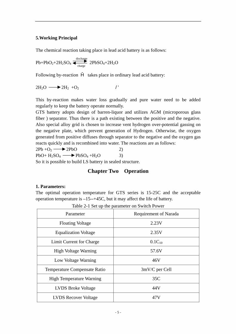
Chapter Two Operation 1. Parameters: The optimal operation temperature for GTS series is 15-25C and the acceptable operation temperature is –15--+45C, but it may affect the life of battery.
Table 2-1 Set up the parameter on Switch Power
Parameter Requirement of Narada
Floating Voltage 2.23V
Equalization Voltage 2.35V
Limit Current for Charge 0.1C10
High Voltage Warning 57.6V
Low Voltage Warning 46V
Temperature Compensate Ratio 3mV/C per Cell
High Temperature Warning 35C
LVDS Broke Voltage 44V
LVDS Recover Voltage 47V
- 5 -

Equalization Charge Cycle 90days
Equalization Charge Time 10h Equalization Charge Conditions after
discharge (Capacity/Voltage) Above 20% DOD
Condition to change Float Charge to Equalization Charge Smaller than 5 0mA/Ah
Equalization Charge Time when Electricity Goes Out 10h
Condition to Stop Equalization Charge 5mA/Ah
Continue Equalization Time 3h
Charge Capacity Rate Larger than 1.2 Times
Capacity of Battery Distributor According to Actual Battery Capacity
Connection of Battery First Series, later Parallel
Rejected battery The Capacity is less than 80% of rated capacity
Terminal Voltage Difference 50 mV /20 mV(Floating/open circuit)
The above data are set at an ambient temperature of 25C. Please refer to Table 3-1 for data under other temperature. Limited Current means output current of switch minus the current that the
telecommunication equipment need. 2.Discharge Curve
Fig. 2-1 Discharge Performance Curves at Different Discharge Rates (25C)
- 6 -
Volta
ge(V
)
Time(h)

Fig. 2-2 Discharge Curve at 1 Minute (25C)
0 .0 0 .2 0 .4 0 .6 0 .8 1 .0 1 .2 1 .4 1 .61 .6
1 .7
1 .8
1 .9
2 .0
2 .1
Volta
ge(V
)
Discharge Rate Kch(Kch=Idis/C10)
- 7 -

Fig. 2-3 Discharge Curve at 5 Seconds (25C)
0 .0 0 .2 0 .4 0 .6 0 .8 1 .0 1 .2 1 .4 1 .61 .6
1 .7
1 .8
1 .9
2 .0
2 .1
Volta
ge (V
)
Discharge Rate Kch(Kch=Idis/C10)
Fig.2-4 Shock Discharge Curve at Different Rate after Discharge for 1h (25C)
0 .0 0 .5 1 .0 1 .5 2 .0 2 .5 3 .01 .5
1 .6
1 .7
1 .8
1 .9
2 .0
2 .1
2 .2
2 .3
Volta
ge (V
)
F
00000
Discharge Rate Kch(Kch=Idis/C10)
- 8 -
loat voltage
Open circuit
.1C
01.2C 01.3C10.4C10.5C10
Fig. 2-5 Shock Discharge Curve at Different Rate after Discharge for 0.5h (25C)
0 .0 0 .5 1 .0 1 .5 2 .0 2 .5 3 .01 .5
1 .6
1 .7
1 .8
1 .9
2 .0
2 .1
0.1C10 0.2C10 0.3C10 0.4C 100.5C10
Volta
ge (V
)
Discharge Rate Kch(Kch=Idis/C10)
3. Charge Performance Fig. 2-6 shows recharge characteristics of 100% DOD GTS-500 battery with current of 0.1C10A and limit voltage of 2.35V/Cell (25C). It can be found that the fully discharged battery is 120% recharged in 24 hours.
Fig.2-6 recharge characteristics of 100% DOD GTS-500 battery with current of 0.1C10A and limit voltage of 2.35V/Cell (25C)
0 4 8 1 2 1 6 2 0 2 40 . 0
0 . 2
0 . 4
0 . 6
0 . 8
1 . 0
1 . 2
1 . 4
1 . 9
2 . 0
2 . 1
2 . 2
2 . 3
2 . 4
0
1 0
2 0
3 0
4 0
5 0
6 0
Voltage Current Capacity Charged
Cap
acity
Cha
rged
Rat
e
Volta
ge (V
)
Cur
rent
(A)
Time(H)
- 9 -
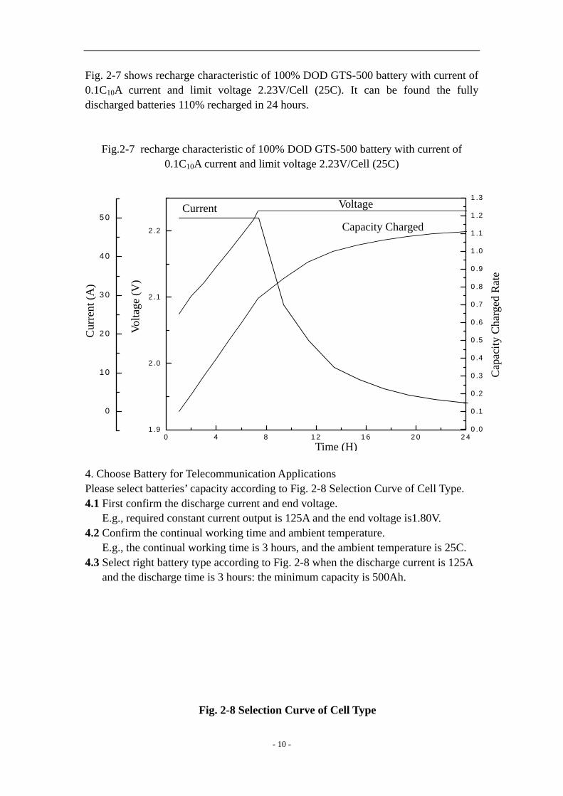
Fig. 2-7 shows recharge characteristic of 100% DOD GTS-500 battery with current of 0.1C10A current and limit voltage 2.23V/Cell (25C). It can be found the fully discharged batteries 110% recharged in 24 hours.
Fig.2-7 recharge characteristic of 100% DOD GTS-500 battery with current of 0.1C10A current and limit voltage 2.23V/Cell (25C)
0 .0
0 .1
0 .2
0 .3
0 .4
0 .5
0 .6
0 .7
0 .8
0 .9
1 .0
1 .1
1 .2
1 .3
0 4 8 1 1 6 2 0 2 41 .9
2 .0
2 .1
2 .2
0
1 0
2 0
3 0
4 0
5 0
Voltage Current Capacity Charged
Cap
acity
Cha
rged
Rat
e
Vlta
ge (V
) o
Cur
rent
(A)
T 4. Choose Battery for Telecommunication ApplicatPlease select batteries’ capacity according to Fig. 24.1 First confirm the discharge current and end vol E.g., required constant current output is 125A a4.2 Confirm the continual working time and ambie E.g., the continual working time is 3 hours, and4.3 Select right battery type according to Fig. 2-8 w and the discharge time is 3 hours: the minimum
Fig. 2-8 Selection Curve
- 10 -
2ime (H)
ions -8 Selection Curve of Cell Type. tage. nd the end voltage is1.80V. nt temperature. the ambient temperature is 25C. hen the discharge current is 125A capacity is 500Ah.
of Cell Type
Single Cell (Final Voltage 1.80V/cell) T=25℃
Discharge Current (A)
Discharge Time
HourMinute
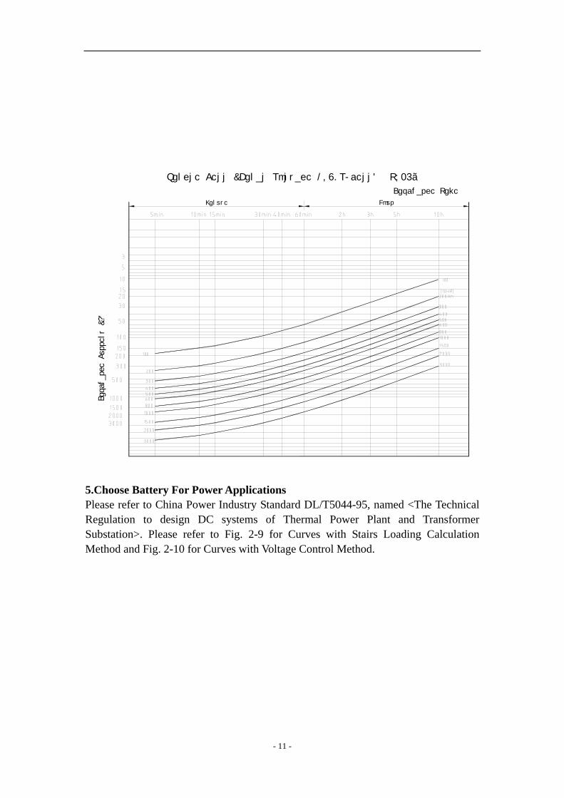
5.Choose Battery For Power Applications Please refer to China Power Industry Standard DL/T5044-95, named <The Technical Regulation to design DC systems of Thermal Power Plant and Transformer Substation>. Please refer to Fig. 2-9 for Curves with Stairs Loading Calculation Method and Fig. 2-10 for Curves with Voltage Control Method.
- 11 -

Fig. 2-9 Curves with Stairs Loading Calculation Method
1 10
7
0.8
0 .9
1 .0
1 .1
0 .0
0 .1
0 .2
0 .3
0 .4
0 .5
0 .6
0 .
0 .0
0 .1
0 .2
0 .3
0 .4
0 .5
0 .6
0 .7
0 .8
0 .9
1 .0
1 .1
5
1 2 3 4
Capacity (C/C10)25C
1- End Voltage 1.60V 2- End Voltage 1.70V 3- End Voltage 1.80V 4- End Voltage 1.90V
Discharge Time (Hour)
Fig. 2-10 Curves with Voltage Control Method
0 60 120 180 240 300 360 420 4800.0
0.1
0.2
0.3
0.4
0.5
0.6
0.7
0.8
0.9
1.0
1.1
1.2
1.3
KCh=Idischarge/C
1- End Voltage1.90V
2- End Voltage1.80V
d V l3 E
4
3
2
1
KCh
(25C)
Time(Min)
- 12 -

6. Internal resistance and short circuit current The internal resistance of the battery is a dynamic nonlinear parameter that is continuously changed along with the temperature and discharge state. The internal resistance is the lowest when battery is fully charged. The table 2-1 shows the internal resistance and short circuit current of Narada battery in fully charged state according to the DL/T 637-1997 standard of Chinese Electric Power Department. Table 2-2. Internal resistance and short circuit current (25C)
Type Internal Resistance(mOhm) Short Circuit Current(A)
GTS-100 1.4 1300
GTS-200 0.514 3940
GTS-300 0.363 5588
GTS-400 0.297 6816
GTS-500 0.218 9361
GTS-600 0.175 11576
GTS-800 0.223 9153
GTS-1000 0.189 10804
GTS-1500 0.152 13237
GTS-2000 0.115 17391 Note: Short circuit current will decrease the voltage of the battery to 0V, and damage the internal components of the battery.
- 13 -
Chapter Three Operation and Maintenance 1. Capacity and Influence Factor 1.1 Capacity of Battery The capacity of battery is the capacity that battery can be discharged on the established conditions, expressed as signal C. The usual unit of capacity is ampere hour, shortened as AH. The capacity can be expressed in Rated Capacity or Actual Capacity. The Rated Capacity of GTS battery please see Table 1-1. The Actual Capacity is the product of the discharge current and the discharge time, the unit is AH. 1.2The Influence Factor of the Actual Capacity The actual capacity is mainly related with the positive and negative active materials and their utilization ratio. The utilization ratio of the materials is mainly influenced with the DOD, the structure of the battery and manufacture technology. In using process the factors that influence the actual capacity are discharge rate, depth of discharge, end voltage and temperature. 1.3 Discharge Rate The discharge rate is often described as hour-rate and multiple rates. Figure 2-1 is the discharge characteristics curves at different discharge rates. From the figure we can see that when we adopt battery to discharge, if the discharge rate is higher and the discharge current is larger, then the discharge time is shorter, and the capacity which can be discharged is less. 1.4 End voltage The end voltage is the lowest working voltage below which the battery can’t be discharged any more without harming the battery. Usually the 10hr rate end voltage of lead-acid battery is 1.80V. The batteries are not able to discharge more capacity even if the end voltage is lower because of characteristics of lead acid battery, yet the low end voltage makes great harm to the battery. It will greatly shorten batteries’ life especially to charge the battery to 0V while not to recharge in time. 2. Available Capacity Vs. Ambient Temperature Temperature affects capacity of the battery. Fig. 3-1 is the available capacity (10h rate) curve vs. ambient temperature. Though VRLA battery can operate at –15C, the standard data is the test result at 25C.
- 14 -
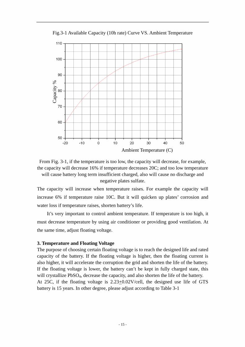
Fig.3-1 Available Capacity (10h rate) Curve VS. Ambient Temperature
Cap
acity
%
From Fig. 3-1, if the tthe capacity will decre
will cause battery lo
The capacity will incr
increase 6% if temper
water loss if temperatu
It’s very importan
must decrease tempera
the same time, adjust f 3. Temperature and FThe purpose of choosincapacity of the batteryalso higher, it will acceIf the floating voltagewill crystallize PbSO4,At 25C, if the floatinbattery is 15 years. In o
Ambient Temperature (C)
emperature is too low, the capacity will decrease, for example, ase 16% if temperature decreases 20C; and too low temperature ng term insufficient charged, also will cause no discharge and
negative plates sulfate. ease when temperature raises. For example the capacity will
ature raise 10C. But it will quicken up plates’ corrosion and
re raises, shorten battery’s life.
t to control ambient temperature. If temperature is too high, it
ture by using air conditioner or providing good ventilation. At
loating voltage.
loating Voltage g certain floating voltage is to reach the designed life and rated . If the floating voltage is higher, then the floating current is lerate the corruption the grid and shorten the life of the battery.
is lower, the battery can’t be kept in fully charged state, this decrease the capacity, and also shorten the life of the battery. g voltage is 2.23+0.02V/cell, the designed use life of GTS ther degree, please adjust according to Table 3-1
- 15 -

Table 3-1 Relationship of ambient temperature and float voltage
Ambient Temperature (C)
Float Voltage (V/Pc)
0~10 2.29 11~15 2.26 16~25 2.23 26~30 2.21 31~35 2.20 36~40 2.19
4. Ambient temperature Vs. Battery Life
The heat disseminate performance of VRLA battery is bad, it’s liable to cause heat run
away when heat accumulates. When temperature exceeds 25C, the battery life will
decrease half per 10C temperature raise.
t25= tT x 2(T-25)/10
Notes: T the actual ambient temperature;
tT is designed life at T ambient temperature
t25 is designed life at 25C ambient temperature
Above-mentioned formula can be used during 10~40C.
For example, the designed life of battery at 25C is 10 years, when battery operates at
35C, the actual life is only 5 years.
5. Requirement for Charge and Discharge
5.1 Equalization Charge The battery need an equalization charge in the following conditions:
— After installation of the battery system, the batteries need to be supplementary charged.
— Floating operation over three months, and the voltage of at least two batteries are lower than 2.18V.
— Storage over three months. — Floating operation for three months.
- 16 -

The method of equalization charge is suggested as follows: — Charge with 2.35V–2.40V/Cell for 24 hours. Note: Above-mentioned charge time is in the condition that temperature changes from 20C to 30C. If the ambient temperature decreases, it’s better to increase the charge time; otherwise, decrease the charge time.
5.2 Charge After discharge, the batteries should be charged in time. The method is recommended as follows:
— The batteries first should be charged on the constant current of 0.1C10A till the average voltage of the batteries increases to 2.35–2.40V, then the batteries should be charged with constant voltage of 2.35–2.40V/Cell, till the charge is finished.
Whether the batteries are fully charged can be decided according to any one of two standards as follows:
— The charge time is 18–24 hours (the charge time can be shortened when the batteries weren’t deep discharged, e.g., the charge time of 20% DOD batteries can be shortened to 10hours.)
— On condition of constant voltage, the value of charge current hasn’t varied for continuous three hours.
On special condition, the batteries need to be fully charged as soon as possible, then fast charge should be adopted: the value of limit current should not be larger than 0.25C10A, and the charge voltage should be 2.35–2.40V per cell.
6.Storage All lead acid batteries experience self-discharge in open circuit. The result is that the voltage of open circuit is decreased, and the capacity also decreased. During storage please note:
— The self-discharge rate is related with ambient temperature. The self-discharge degree is smaller when the ambient temperature is lower, otherwise is larger. The requirement temperature of GASTON GTS batteries’ storage environment is from 0C to 35C. The storage place must be clean, ventilated and dry.
— An important parameter in storage is open circuit voltage, which is related with density of the electrolyte. In order to avoid permanent damage to the plate caused by self-discharge, the batteries should be supplementary charged if they have been stored for three months. The equalization charge method should be adopted.
— During storage, if the open circuit voltage is lower than 2.10V/Cell, the batteries should be supplementary charged before use. The equalization charge method should be adopted.
— All batteries, which are ready to store, should be fully charged before storage. It’s suggested record the storage time in the periodic maintenance record and
- 17 -

record the time when another necessary supplementary charge should be made.
— The quality certificates of GTS batteries record the latest charge time of the batteries, next charge time can be calculated according to this charge time.
7. Maintenance In order to assure service life, the batteries should be correctly inspected and maintained. The maintenance methods of GTS batteries are recommended as follows: 7.1 Monthly Maintenance Implement the under-mentioned inspection every month:
— Keep the battery-room clean. — Measure and record the ambient temperature of the battery-room. — Check each battery’s cleanness; check damage and overheating trace of the
terminal, container and lid. — Measure and record the total voltage and floating current of the battery
system.
7.2 Quarterly Maintenance — Repeat monthly inspection. — Measure and record floating voltage of every on-line battery. If more than two
cells’ voltage is less than 2.18V after temperature adjustment, the batteries need to be equalization charged. If the problem is still existing after adopting above-mentioned measures, the batteries need yearly maintenance or even three years’ maintenance. If all methods are ineffective, please contact us.
7.3 Yearly Maintenance
— Repeat quarterly maintenance and inspection. — Check whether connectors are loose or not every year. — Make a discharge test to check with exact load every year, discharging
30-40% of rated capacity.
7.4 Three-year Maintenance — Make a capacity test every three years and every year after six years’
operation. If the capacity of the battery decreases to lower than 80% of rated capacity, the battery should be replaced.
7.5 Operation and Maintenance Precautions A. Insufficient Charge
If the floating voltage is not set correctly (too low or not amend according to temperature), the battery system will in an insufficient charge state for a long period of time. When the electricity is out, the battery may not be able to work because the acid is saltilized and the capacity is decreased.
B. Over Charge
- 18 -
Please do not neglect the performance of rectify to transfer floating charge to equalization charge. If the rectify cannot transfer charge modes because of its wrong performance or no adjustment, the battery system is always in an equalization charge state. Thus may cause serious problems for battery, such as water loss, life decrease, heat out of control, deformation, etc.
C. Too low or too high temperature We have mentioned that too low temperature will affect the capacity of battery. While too high temperature will also cause problems, such as water loss, life decrease, heat out of control, deformation, etc.
D. Too low end voltage The end voltage is also an important parameter for battery. The battery shall stop discharge when reach a certain voltage (The normal end voltage is 1.8V). If the end voltage is too low, it will be difficult to recharge the battery and decrease the charge efficiency, thus reduce the life of battery.
E. Do not charge the battery immediately after discharge. If the battery is put aside without charge for a long time (2 hours above) after discharge, it will affect the capacity and life of the battery. Because some large size PbSO4 will create in the negative which are difficult to transfer to active Pb.
F. Use insulating instruments in operating and maintaining batteries. Do not lay metal instruments on batteries. G. Do not use any organic cleanser to clean batteries. H. Do not take out the safety valves of batteries and add anything into batteries. I. Do not smoke or use fire near batteries. J. Do not use abnormal batteries. K. All maintenance works should be done by professionals.
- 19 -
Chapter Four Installation 1.Vertical Installation 1.1 Check battery to assure no damage after unpacking, check accessories against packing list to
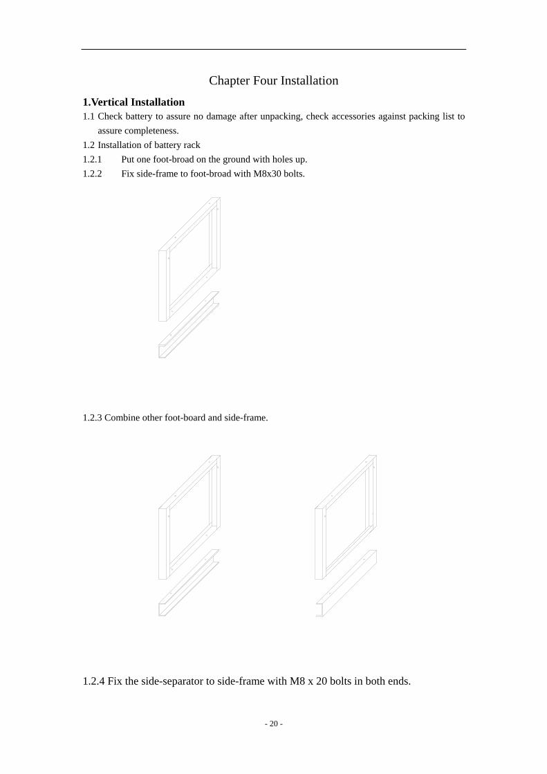
assure completeness. 1.2 Installation of battery rack 1.2.1 Put one foot-broad on the ground with holes up. 1.2.2 Fix side-frame to foot-broad with M8x30 bolts.
1.2.3 Combine other foot-board and side-frame.
1.2.4 Fix the side-separator to side-frame with M8 x 20 bolts in both ends.
- 20 -

1.2.5 Fix the other side-separator as1.2.4. Insert middle separator into side-frame.
Please refer to 1.2.9 if it is one layer installation
1.2.6 Fix the side-frame of second layer to the side-frame of first layer with M8 x 20
bolt.
- 21 -

1.2.7 Fix the side-separator according to 1.2.4 and 1.2.5.
Please refer to 1.2.9 if it is two layers rack
1.2.8 Installation the third floor according to 1.2.6 and 1.2.7.
- 22 -

1.2.9 Put the cover broad and connect wit M8 x 20 bolt.
1.2.10 Please connect each row with M8x20 bolts if there are several rows
1.2.11 Adjust the rack and screw bolts tightly when the racks are in their place.
1.2.12 Batteries of same group number are installed in one system. Push the battery
Inside the rack according to installation drawings. Please leave 30mm space between
battery and rack and 10mm space between each battery.
- 23 -

1.2.13 Install the Terminal board at output side and install protection board at other
side.
1.2.14 Connect positive post of first battery and negative post of last battery to
terminal board with output connectors.
1.2.15 Connect each battery steadily with connectors. Screw connectors tight with
torque of 15Nm. Put on the connector cover. Test the total voltage of battery with
multimeter to ensure the polarization.
1.2.16 Connector Power to terminal broad corresponding the positive and negative
- 24 -
post. Insert insulate board.
1.2.17 Clean the battery, rack and terminal board with soft cloth.
1.2.18 Check connection and put the code of battery when ensuring the connection is
correct. Mark the positive and negative post. Check whether all bolts are tight. We can
set up the electric cycle when everything is correct.
2.Horizontall Installation 2.1 Check battery to assure no damage after unpacking, check accessories against packing list to assure completeness. 2.2 Check battery to assure no damage after unpacking, check accessories against packing list to assure completeness.
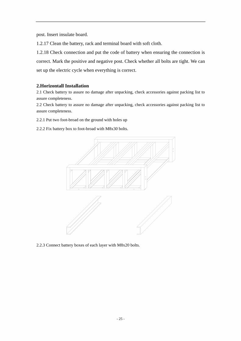
2.2.1 Put two foot-broad on the ground with holes up
2.2.2 Fix battery box to foot-broad with M8x30 bolts.
2.2.3 Connect battery boxes of each layer with M8x20 bolts.
- 25 -

2.2.4 Repeat above steps if there are several rows.
2.2.5 Please connect each row with M8x20 bolts. Two bolts, one in the front and the
other in the end, are enough for one battery box.
2.2.6 Install the terminal board at output side. Adjust the rack and screw bolts tightly
- 26 -
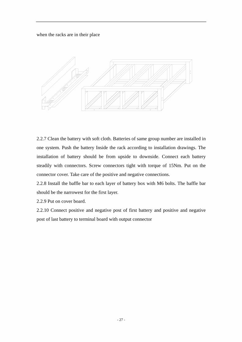
when the racks are in their place
2.2.7 Clean the battery with soft cloth. Batteries of same group number are installed in
one system. Push the battery Inside the rack according to installation drawings. The
installation of battery should be from upside to downside. Connect each battery
steadily with connectors. Screw connectors tight with torque of 15Nm. Put on the
connector cover. Take care of the positive and negative connections.
2.2.8 Install the baffle bar to each layer of battery box with M6 bolts. The baffle bar
should be the narrowest for the first layer.
2.2.9 Put on cover board.
2.2.10 Connect positive and negative post of first battery and positive and negative
post of last battery to terminal board with output connector
- 27 -

Annex 1 VRLA Battery Regular Maintenance Record
Type Place Status Number of battery Total Voltage(V) Current (A) Temperature No. Voltage(V) No. Voltage(V) 1 13 2 14 3 15 4 16 5 17 6 18 7 19 8 20 9 21 10 22 11 23 12 24 Check by sight Result:
Tester: Date:
- 28 -